

RIDGID SS1650 1 Owner's Manual

66
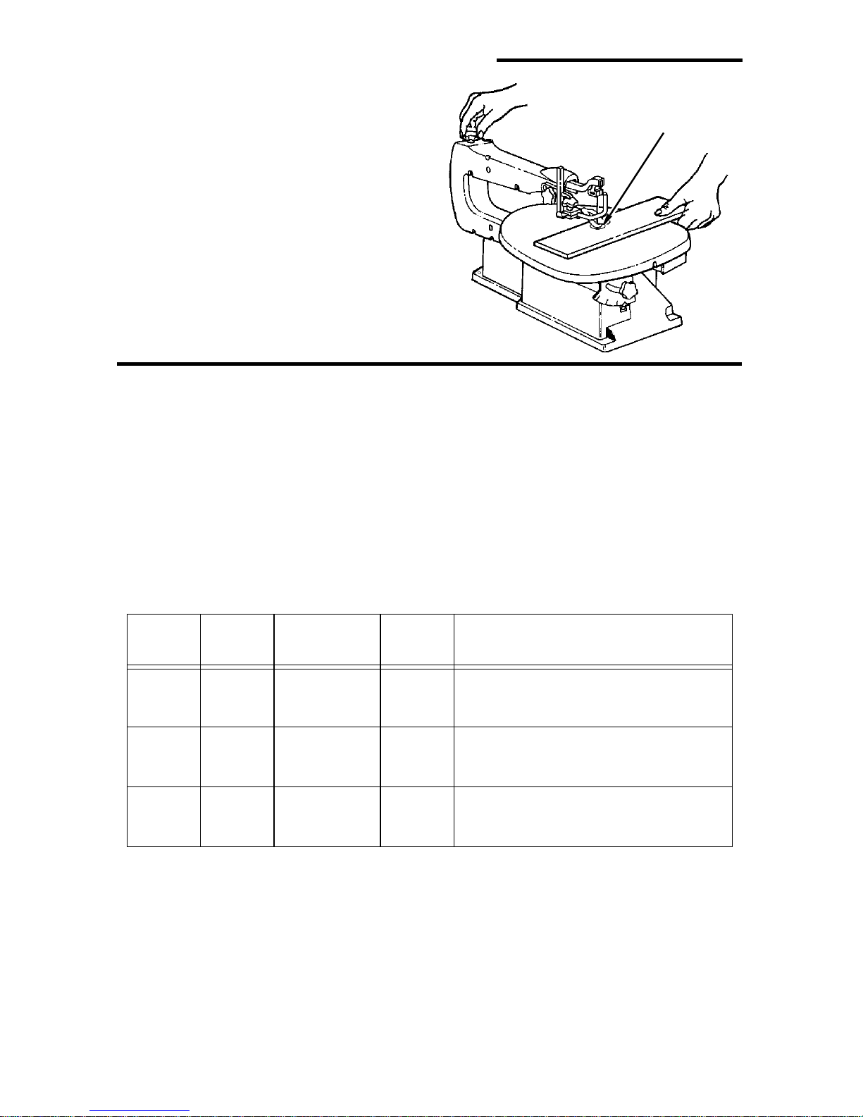
2:1(560$18$/
)RU<RXU6DIHW\
5HDGDOOLQVWUXFWLRQVFDUHIXOO\
,1&+9$5,$%/(
63(('6&52//6$:
Part No. SP6356 Printed in U.S.A.

Table of Contents
Section Page
Table of Contents ..................................2
Safety Instructions for Scroll Saw ..........2
Safety Signal Words ...........................2
Before Using The Saw .......................2
When Installing or Moving The Saw ...3
Before Each Use ................................3
Plan Ahead To Protect Your Eyes,
Hands, Face and Ears ......................4
Whenever Saw Is Running .................5
Before Leaving the Saw .....................5
Glossary of Terms for Woodworking .....6
Motor Specifications and Electrical
Requirements .................................... 6
Power Supply and Motor
Specifications ...................................6
General Electrical Connections ..........6
110-120 Volt, 60 Hz. Tool Information 7
Wire Sizes ..........................................8
Unpacking and Checking Contents 8
Tools Needed .....................................8
Unpacking .......................................... 8
List of Loose Parts .............................8
Getting to Know Your Scroll Saw ...........9
Alignment (Adjustments) ......................11
Changing the Table Bevel Angle ......11
To Adjust 90° Table Stop and Align the
Bevel Indicator ................................ 11
Adjusting Work Hold-down ...............12
Over Tensioning Or Under Tensioning
Blade ..............................................12
Section Page
Removing Pin End Blades ...............13
Installing 5" Pin End Blades .............14
Removing Plain End Blades ............15
Installing 5" Plain End Blades ..........16
Dust Blower .....................................17
Blade Guard .....................................17
Sawdust Collection Port ...................17
Mounting the Scroll Saw ......................18
Workbench Applications ..................18
Safety Instructions for Basic Saw
Operations ................ ..... ...... ...... ..... .19
Before Each Use ..............................19
Plan Ahead To Protect Your Eyes,
Hands, Face And Ears ...................19
Whenever Saw Is Running ..............20
Before Leaving The Saw .................21
Basic Saw Operations .........................21
General Instructions .........................21
Making Interior Scroll Cuts ...............21
Choice of Blade and Speed .............22
Maintenance ........................................ 23
General ............................................ 23
Motor/Electrical ................................ 23
Arm Bearings .................................. .23
Troubleshooting ...................................24
Wiring Diagram ....................................25
Repair Parts ........................................26
Safety Instructions for Scroll Saw
Safety is a com bination of common
sense, staying alert and knowing how
Safety Signal Words
DANGER: mean s if the s afe ty inf ormation
is not followed someone will be seriously
injured or killed.
WARNING: means if the safety information is not followed someone could be
Before Using The Saw
WARNING:
mistakes that could cause serious
permanent injury, do not plug the
saw in until the follow ing step s are
completed.
To reduce the risk of
your scroll saw works. Read this manual
to understand this saw.
seriously injured or killed.
CAUTION: means if the safety informa-
tion is not followed someone may be
injured.
• Completely assemble and align saw
(see “Assembly and Alignment” sections
within).
2

• Learn the use and function of the speed
control ON-OFF knob, bevel lock knob ,
blade holders, blade support, hold down,
tension knob, and blade guard. (See “Getting to Know Your Scroll Saw” section.)
• Read the warning label below, which is found on the base of the saw.
• Review and understand all safety
instructions and opera ting p roc edures in
this manual.
• Review the maintenance methods for
this saw. (See “Maintenance” section.)
When Installing or Moving The Saw
To Reduce the Risk of Dangerous Environment. Use the saw in a dry indoor
place, protected from rain. Keep work
area well lighted .
To reduce the risk of injury from unexpected saw movement:
• Turn saw off and unplug cord before
moving the saw.
• Place the saw on a firm level surface
where there is plenty of room for handling and properly supporting the workpiece.
• Support the saw so the t ab le is le v e l and
the saw does not rock.
• Bolt the saw to the work surface if it
tends to slip, walk, or slide during opera-
tions like cutting long heavy boards, or
when using an auxiliary table.
To reduce the risk of injury or death
from electrical shock:
• Ground the saw. This saw has an
approved 3 conductor cord and a 3prong grounding type plug. Use only 3wire, grounded outlets rated 120 volts,
15 amperes (amps). The green conductor in the cord is the grounding wire. To
reduce the risk of electrocution, NEVER
connec t the green wire to a live terminal.
• Make sure your fingers do not touch the
plug’s metal prongs when plugging or
unplugging the saw.
Before Each Use
Inspect your saw.
Disconnect The Saw. To red uce the risk
of injury from accidental starting, unplug
the saw, turn the switch off and lock out
the switch before changing the setup,
removing covers, guards or blade.
Check For Damaged Parts. Check for:
• Ali gnment of moving parts.
• Binding of moving parts.
• Broken parts.
• Stable mounting.
• A ny other cond ition that may affect the
way the saw works.
If any part is missing, bent or broken in
any way, or any electrical part doesn’t
work properly , turn the saw
the saw. Replace damaged, missing or
failed parts before using the saw again.
Keep Guard In Place and in working
order.
3
off and unplug
Safety Instructions for Scroll Saw (continued)
Maintain Tools with Care. Keep the saw
clean for best and safest performance. Follow instructions fo r lubricating.
To reduce the risk of injury from jams,
slips or thrown pieces
• Use Only Recommended Accessories. Follow the instructions that come
with the accessor ies. The use of
improper accessories may cause risk of
injury to person.
• Choose the right si z e a nd style bl ade for
the material and the type of cutting you
plan to do.
• Make s ure the blade teeth point downward, toward the table.
• Make sure the blade tension is properly
adjusted.
• Keep Work Area Clean. Cluttered areas
and benches invite accidents. Floor
must not be slippery.
To reduce the risk of burns or other fire
damage, never use the saw near flammable liquids, vapors or gases.
• Know Your Saw. Read and understand
the owners manual and labels affixed to
the tool. Learn its application and limitations as well as the specific potentia l
hazards peculiar to this tool.
• To reduce the risk of inju ry from a ccide ntal contact with moving parts, don't do
layout, assembly, or setup work on the
saw while any parts are moving.
• Reduce the Risk of Accidental Start-
ing. Make sure switch is "OFF" before
plugging saw into a power outlet.
Plan Your Work.
• Use The Right Tool. Don't force tool or
attachment to do a job it was not
designed for.
• Use this scroll saw to cut only wood,
woodlike products, plastics and nonferrous metals.
CAUTION: This saw is NOT
designed for cutting ferrous metals
like iron or steel. When cutting nonferrous metals (brass, copper and
aluminum, etc.), metal shavings can
react with wood dus t a nd start a fire.
To reduce the risk of fire:
• Remove all traces of wood dust
from on and around the saw.
• Remove al l metal shavings fr om on
or around the saw before sawing
wood again.
Plan Ahead To Protect Your Eyes, Hands, Face and Ears
Any power saw can throw foreign objects
into the eyes. This can cause permanent
eye damage . Alw a ys w ear saf e ty gogg les,
not glasses, complying with ANSI Z87.1
(or in Canada CSA Z94.3-99) shown on
package. Everyday eyeglasses have only
impact resistant lenses. They are not
safety glasses. Safety goggles are available at many loca l retail stores. Glasses
or goggles not in compl iance w ith ANSI or
CSA could seriously hurt you when they
break.
Dress for safety
• D o not wear l oose clothing, gloves,
neckties or jewelry (rings, wristwatches).
They can get caught and draw you into
moving parts.
• Wear nonslip footwear.
• Tie back long hair.
• Roll long sleeves above the elbow.
• Noise levels vary widely. To reduce the
risk of possible hearing damage, wear
ear plugs or muffs when using saw for
hours at a time.
• For dusty operations, wear a dust mask
along with the safety goggles.
Inspect Your Workpiece.
Make sure there are no nails or foreign
objects in the part of the workpiece to be cut.
4

Use extra caution with large, very
small or awkward workpieces
• Never use this tool to finish pieces too
small to hold by hand.
• Use extra supports (tables, saw horses,
blocks, etc.) for any workpieces large
enough to tip when no t hel d down to the
table top.
• Never use another person as a substitute for a table extension, or as additional support for a workpiece or to help
feed, support or pull the workpiece.
• When cutting irregularly shaped workpieces, p lan y our wo rk so it w ill not p inch
the blade. A piece of molding, for example, must lay flat or be held by a fixture
or jig that will not let it twist, rock or slip
while being cut.
• Properly support round material such as
dowel rods or tubing. They have a tendency to roll during a cut, causing the
blade to “bite”. To avoid this, always use
“V” blocks.
• Clear everything except the workpiece
and related su pport devices off the tab le
before turning the saw on.
Plan the way you will hold the workpiece from start to finish.
• Do not hand hold pieces so small that
your fingers will go under the blade
guard. Keep your hands away from the
blade.
• R educe th e Risk of awkward operations
and hand positions where a sudden slip
could cause fi ngers or h and to mo v e into
the blade.
• Don’t Overreach. Keep good footing
and balance.
• Keep your face and body to one side of
the blade, out of line with a possible
thrown piece if the blade should break.
Whenever Saw Is Running
WARNING:
(gained from frequent use of your
scroll sa w) cause a careless mi stake.
A careless fraction of a second is
enough to cause a severe injury.
• Before starting your cut, watch the saw
while it runs. If it makes an unfamiliar
noise or v ibra tes excessively, stop imme diately. Turn the saw off. Unplug the saw.
Do not restart until finding and correcting
the problem.
• Keep Children Awa y. Keep all vis itors a
safe distance from the saw. Make sure
bystanders are clear of the saw and
workpiece.
• Don’t Force T ool . It will do the job better
and safer at its designed rate. Feed the
workpi ece into the saw blade only fast
enough to le t it cut w ithout bogg ing dow n
or binding.
Don’t let familiarity
Before Freeing Any Jammed Material.
• Turn switch “OFF”
• Wait for all moving parts to stop.
• Unplug the saw .
When backing up the workpiece, the
blade may bind in the kerf (cut). T his is
usually caused by sawdust clogging
up the kerf. If this happens:
• Turn switch “OFF”.
• Wait for all moving parts to stop.
• Unplug the saw .
• With a flat blade screwdriver, turn motor
shaft by han d. Insert the screwd river into
the slotted end of motor shaft located at
the center of the motor housing. Do this
while backing up the w orkpie c e.
Before remo ving loose piec es from the
table, turn saw off and wait for all moving parts to stop.
Before Leaving the Saw
• Wait for all moving parts to stop.
• Make Workshop Child-proof . Unplug
the saw. Lock the workshop and ON/OFF
knob on the saw . Store the k ey a wa y from
children and others not qualified to use
the tool.
5

Glossary of Te rms f or Woodworking
Kerf - the slot cut by the blade.
Leading Edge - the edge of the work-
piece which is pushed into the blade first.
Sawblade Path - the area of the work-
piece directly in line with and moving
toward the sawblade edge.
Bevel - the ability to slant the table to
make angle cuts. An angle cutting operation through the face of the board.
Blade Tooth Set - the distance that the
edge of the s awb lade t ooth is bent (or set)
outward from the side of the blade.
Plain End Blade - blade ends are flat,
and are clamped in the blade holders.
Pin End Blade - blade ends contain a pin
oriented at 90° to the blade. Blade ends
are hooked into a groove in the blade
holder and clamped.
Trailing Edge - the workpiece edge last
cut by the sawblade.
Wo rkpiece - the item on which the cutting
operation is being performed.
Motor Specifications and Electrical Requirements
Power Supply and Motor Specifications
W ARNING
electrical hazards, fire hazards or
damage to the tool, use proper circuit
protection. Your tool is wired at the
factory for operation using the voltage shown. Connect tool to a power
line with the appropriate voltage and
a 15-amp branch circuit. Use a 15amp time delay type fuse or circuit
breaker . To reduce the risk of shock
or fire, if power cord is worn or cut, or
damaged in any way, have it r eplaced
immediately.
For replac ement motor and control board,
refer to parts list in this manual.
: To reduce the risk of
CAUTION: A direct current motor is
used in this saw. Changes to the
internal wiring will create a fire hazard and may also create a shock hazard.
This machine is equipped with a variable
speed motor having the following specifications:
Voltage 110-120
Amperes 1.2
Hertz (Cycles) 60
Phase Single
RPM 500-1700
General Electrical Connections
DANGER:
electrocution:
• Use only identical replacement
parts when servicing. Servicing
should be performed by a qualified
service technician.
• Do not use in rain or where floor is
wet.
This tool is intended for indoor residential use only.
To reduce the risk of
Rotation of Shaft Clockwise
WARNING: Do not permit fingers to
touch the terminals of plug when
installing or removing the plug to or
from the outlet.
If power cord is worn or cut, or damaged
in any way, have it replaced immediately.
6
110-120 Volt, 60 Hz. Tool Information
NOTE: The plug supplied on your tool
may not fit in to the outlet y ou are planni ng
to use. Your local electrical code may
require slightly different power cord plug
connections. If these differences exist
refer to and m ake the proper adjustm ents
per your local code before you r tool is
plugged in and turned on.
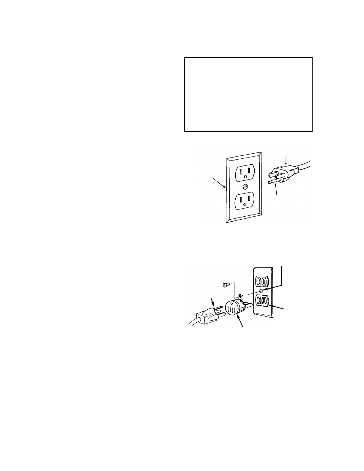
In the event of a malfunction or breakdown, grounding provides a path of least
resistance for electric current to reduce
the risk of electric shock. This tool is
equipped with an electric cord having an
equipment grounding conductor and a
grounding plug, as shown. The plug must
be plugged into a matching outlet that is
properly installed and grounded in accordance with all local codes and ordinances.
Do not modify the plug provided. If it will
not fit the outlet, have the proper outlet
installed by a qualified electrician.
A temporary adapter may be used to connect this plug to a 2-pole ou tlet, as sho wn,
if a properly grounded outlet is not available. This temporar y adapter should be
used only un til a p roperly grounded outlet
can be installed by a qualified electrician.
The green colored rigid ear, lug and the
like, extension from the adapter must be
connected to a permanent ground such
as a properly grounded outlet box.
Improper connection of the equipment
grounding c onductor c an resul t in a risk of
electric shock. The conductor with insulation having an outer surface that is green
with or without yellow stripes is the equipment grounding conductor. If repair or
replacement of the ele ctric cord or plug is
necessary, do not connect the equipmentgrounding conductor to a live terminal.
If the grounding instructions are not completely understood, or if you are in doubt
as to whether the tool is properly
grounded check with a qualified electrician or service personnel.
WARNING: If not properly
grounded, this tool can cause an
electrical shock, particularly when
used in damp locations, in proximity
to plumbing, or out of doors. If an
electrical shock occurs there is the
potential of a secondary hazard,
such as your hands contacting the
sawblade.
Properly
Grounded
Outlet
Green
Grounding Lug
3-Prong
Plug
Adapter
NOTE: The adapter illustrated is for use
only if you already have a properly
grounded 2-prong outlet.
NOTE: Use of a temporary adapter is not
permitted by the Canadian Electrical
Code.
3-Prong Plug
Grounding
Prong
Make sure this
Is Connected
to a Known
Ground
2-Prong
Outlet
7
Motor Specifications and Electrical Requirements (continued)
Wire Sizes
NOTE: Make sure the proper extension
cord is used and is in good condition.
The use of any extension cord will cause
some loss of power. To keep this to a minimum and to prevent overheating and
motor burn-out, use the table shown to
determine the minimum wire size
(A.W.G.) extension cord.
Use only 3-wire extension cords which have
3-prong grounding type plugs and 3-pole
receptacles which accept the tools plug.
Extension
Cord Length
26-50 Ft.
Unpacking and Checking Contents
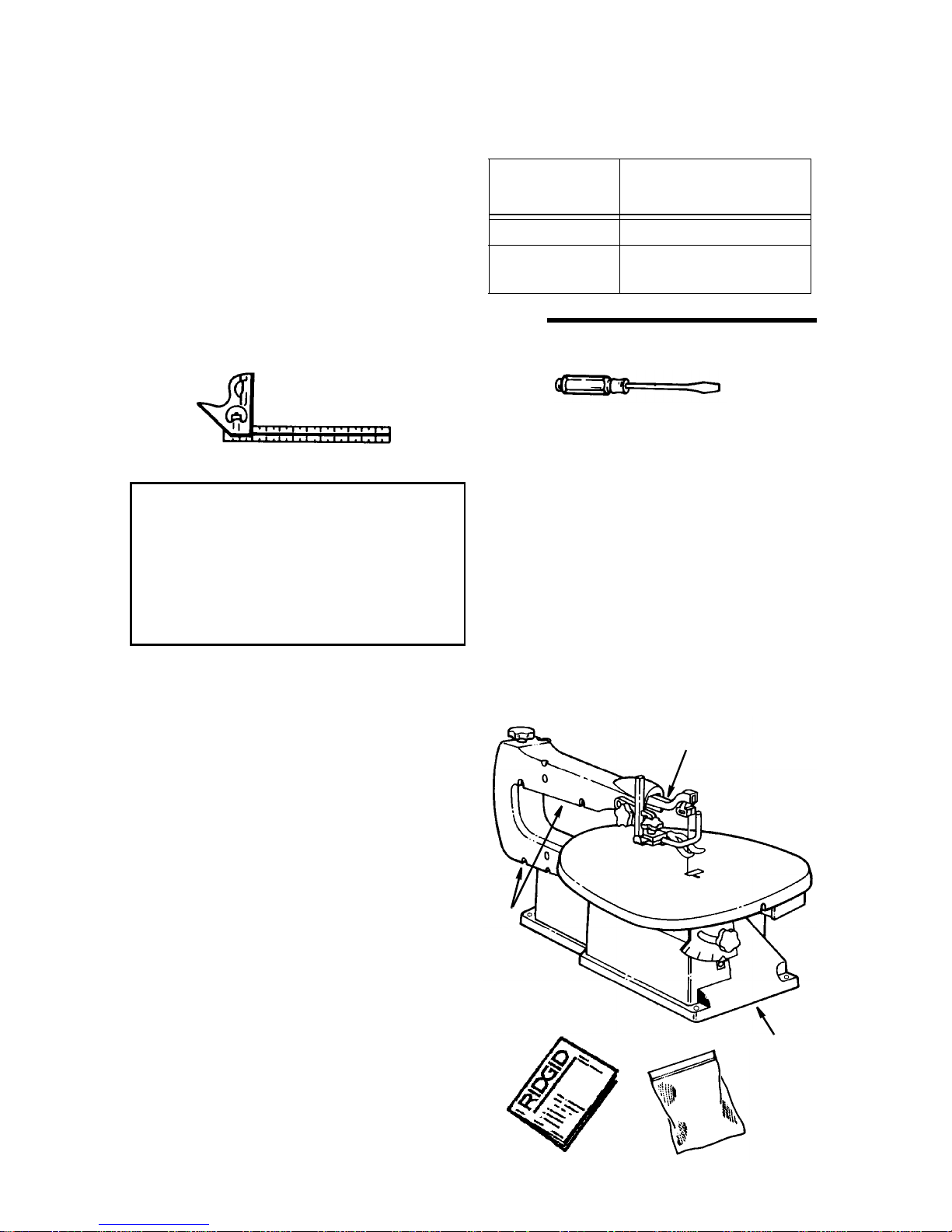
Tools Needed
Combination Square
Unpacking
W ARNING
injury, from unexpected starting or
electrical shock, do not plug the
power cord into a power sour ce outlet
during unpacking and assembly. This
cord must remain unplugged whenever you are w orking on the saw.
Your scroll saw is fully assembled and
shipped complete in one box.
IMPORTANT: Never lift this saw by the
arm which holds th e blade or damage will
occur to your saw.
Separate all parts from packaging materials and check each item with illu stration
and "List of Loose Pa rts". Make certain all
items are accounte d f or bef ore dis cardi ng
any packaging material.
NOTE: If you are missing any part, call 1800-4-RIDGID or E -mail us at info@ridgidwoodworking.com to get the missing
part. Sometimes small parts can get lost
in packaging material. DO NOT throw
away any packaging until saw is put
together. Check packaging for missing
parts before contacting RIDGID. A complete parts list (Repair P a rts) is at the end
of the manual. Use the list to identify the
number of the missing part.
: To reduce the risk of
List of Loose Parts
Item Description Qty.
A 16" Scroll Saw
(Completely Assembled)............... 1
B Owner’s Manual............................. 1
C Loose Parts Bag containing:
Blade........................................1
NOTE: Hardwa re to mou nt th is sc rol l saw
to a bench is not supplied. See mounting
instructions for recommended hardware
size.
Lift
Here
B
0-25 Ft.
Medium Standard and
Phillips Screwdriver
A
Gauge
(A.W.G.)
110-120V
18
16
Do Not Lift Saw
By This Arm
Lift Here
C
8
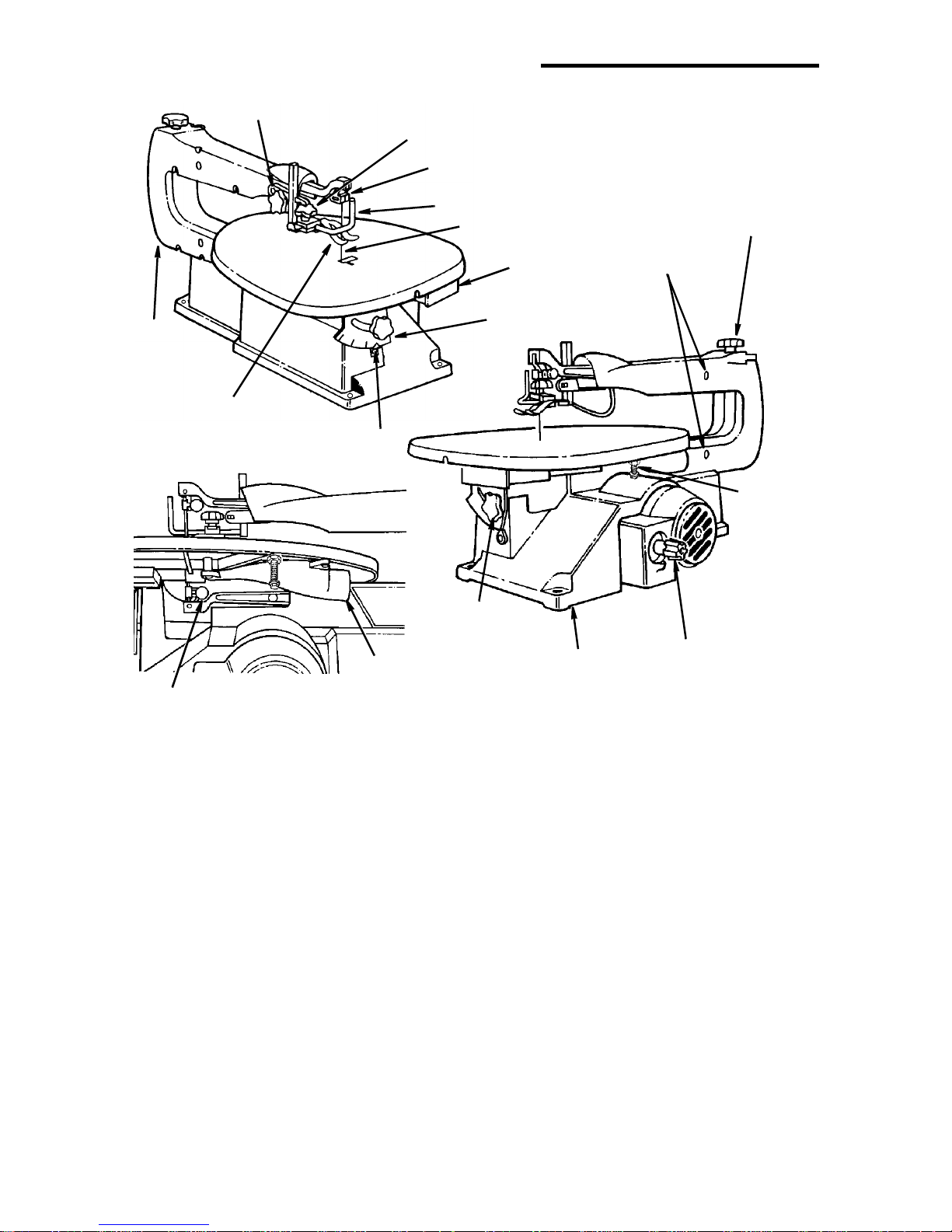
Getting to Know Your Scroll Saw
1 Height
Adjusting Knob
2 Blade Guard/Hold-Down Knob
3 Upper Blade Holder
Frame
(Lift Here)
8 Work Hold-Down Foot
and Blade Support
3 Lower Blade Holder
7 Bevel
Indicator
9 Sawdust
Collection
Port
4 Blade Guard
Blade
5 Storage
6 Bevel Scale
10 Table Bevel
Lock Knob
Drawer
(Lift Here)
Base
11 Blade
Tension Knob
Arm
Bearings
12 Table
Stop
13 Speed Control
On/Off Knob
1. Height Adjustment Knob - Allows
for vertical positioning of b lade guard/
hold down.
2. Blade Guard/Hold Down Knob -
Allows for secure angular positioning
of blade guard, work hold down and
sawdust bl ower.
3. Blade Holders - Retain and position
the blade.
4. Blade Guard - Defines area of mov-
ing blade.
5. Storage Drawer - For convenient
storage of pin and plain blades.
6. Bevel Scale - Shows angle table is
tilted for bevel cutting.
7. Bevel Indicator - Points to the
approximate angle of the blade in
relation to the table top.
8. Work Hold-Down and Blade Sup-
port - Provides added control of
workpiece, protection for operator
and support for the blade.
9. Sawdust Collection Port - Hook up
a wet/dry vac to help cont rol sa w dust.
10. Table Bevel Lock Knob - When
tightene d, this knob secur es table at
desired bevel angle. Loosening knob
allows the table to tilt up to 45° for
bevel cuts.
11. Blade Tension Knob - Tightening
the knob (c lo ckwi se) wi l l i n cre as e the
tension on the blade. Loosening it
(counterclockwise) will decrease the
tension.
12. Table Stop - Allows table to be tilted
and returned to accurate 90° stop.
9
Getting to Know Your Scroll Saw (continued)
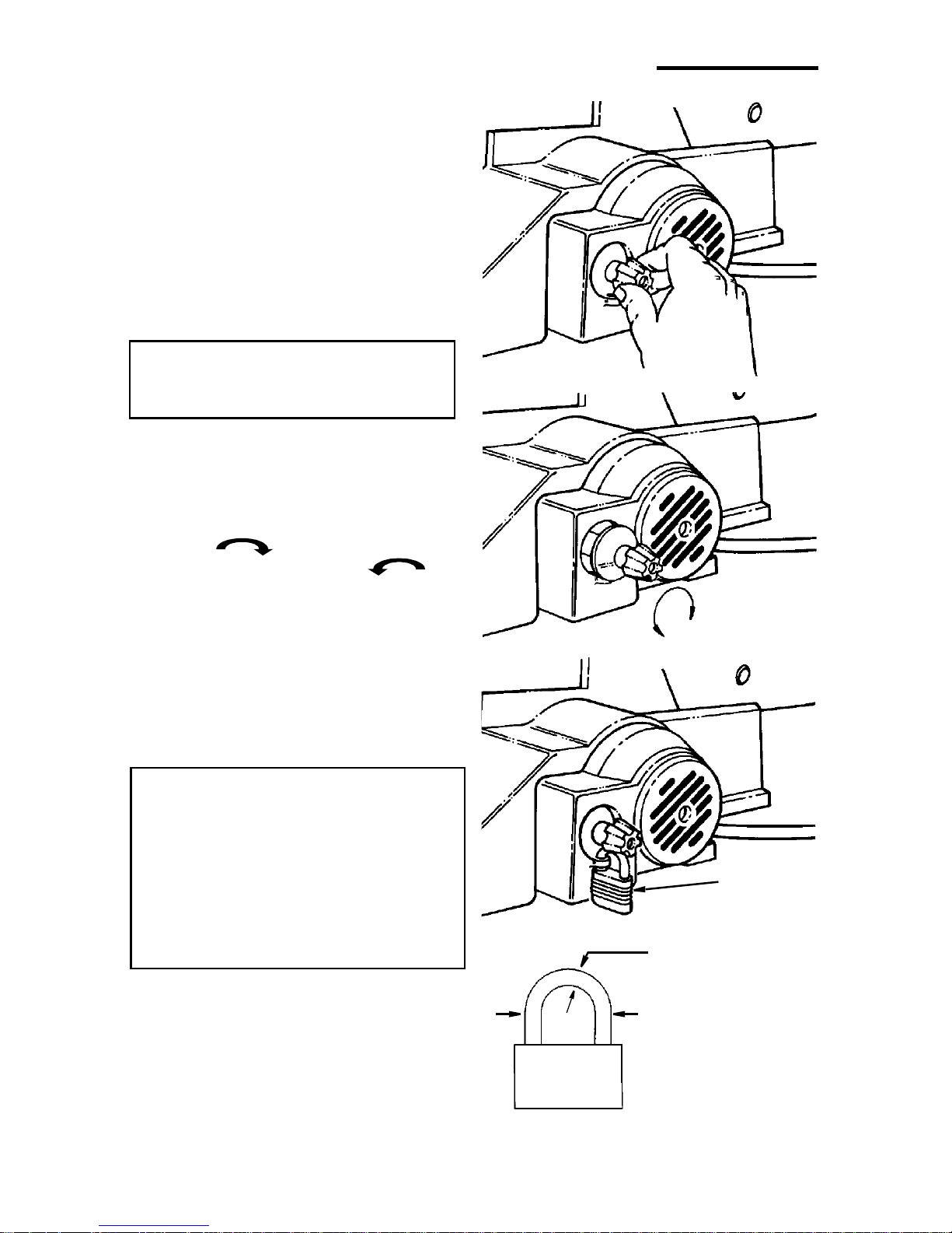
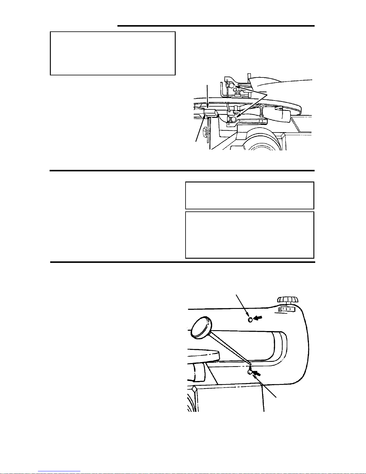
13. Speed Control/On-Off Knob - For
speed control setting, refer to the
“Choice of Blade and Speed” table.
The On-Off knob has a locking feature, This Feature Is Intended To
Help Prevent Unauthorized Use By
Children And Others.
• To turn machine “ON”, place fingers
on Speed Control/On-Off Knob and
pull out.
• To turn machine “OFF”, push in
Speed Control/On-Off Knob.
WARNING: Never lea ve the machine
unattended until it has come to a
complete stop.
The variable speed contr ol may be
adjusted to the approximate speeds identified on the control panel. Suggested
speeds are identified under “Choice of
Blade and Speed”. Turn the control knob
clockwise to increase strokes per
minute and counterclockwise to
reduce the strokes per minute.
Rotate
Speed
Control
• To lock knob in “OFF” position, install
a padlock through the hole below
the knob as illustrated, and lock the
padlock. (Padlock is not supplied
with the saw.)
WARNING: For your own safety,
always push the knob “Off” when
machine is not in use. Also, in the
event of a power failure (all of your
lights go out), push knob “Off”.
“Lockout” your knob with a padlock
as shown. This will prevent the
machine from starting up again
when the power comes back on.
Install
Padlock
Through Hole
5/32 to 3/16 Inch
Approximate
Diameter
1 Inch Approximate
Approximate
Padlock Size
10
Alignment (Adjustmen ts)
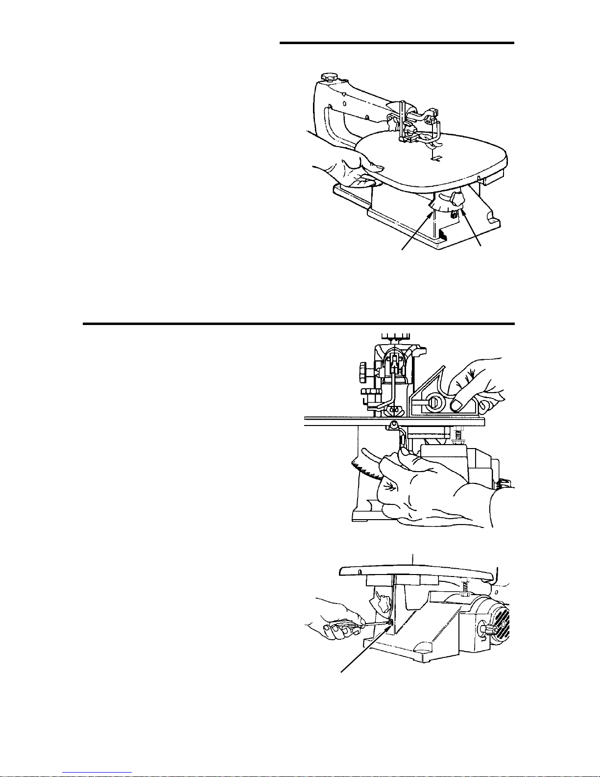
Changing the Table Bevel Angle
• The scroll saw w ork tabl e can be tilt ed to
the left for bevel cutting up to 45° from
the 0° or horizontal cutting position.
• A bevel s ca le a nd indicator are provided
under the work table as a convenient reference for setting the approximate table
angle for bevel cutting.
• A 90° table stop is provided under the
table to allow the table to be tilted and
returned to an accurate 90°.
NOTE: A scroll saw is a scroll curve cutting tool. It is not intended for making
precise angular cuts in wood. The indicator is provided to g ive approximate
angular readings. A precision protractor
or square should be used to measure a
more precise b l ade to t ab le ang ular lo ca tions.
Bevel
Scale
Bevel
Lock Knob
To Adjust 90° Table Stop and Align
the Bevel Indicator
• Loosen the table bevel lock knob and
use a small square to set the table at 90°
to the blade.
• Loosen the table stop jam nut and adjust
the stop bolt in or out to accurate 90°.
• Tig hten the jam nut.
• When there is no space between the
square and the b lade , hold tab le in pla ce
and tighten the bevel lock knob. The
table should now be approximately 90°
to the blade.
• Loosen the screw holding the bevel
scale pointer and adjust to 0°. Tighten
screw.
Remember, the bevel scale is a convenient guide but should not be relied
upon for precision.
Bevel
Pointer
11
Alignment (Adjustments) (continued)
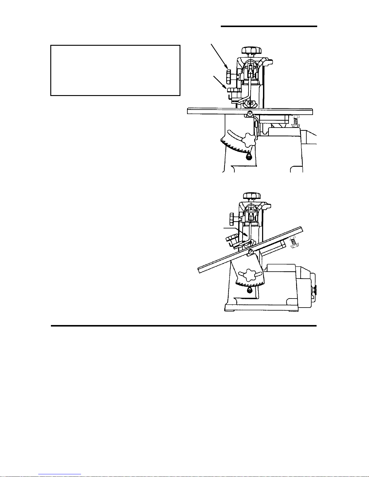
Adjusting Work Hold-down
WARNING
injury from accidental starting,
always turn switch "OFF" and
unplug power cord from outlet
before removing or replacing the
blade.
The purpose of the work hold-do wn f oot is
to hold the work aga inst the tab le so that it
is less likely to lift with the up stroke of the
blade. It should lie flat on the workpiece
with the front prongs straddling the blade.
1.The work hold-down foot is attached to
the blade guard rod. The height of the
work hol d-down foot is ad justed by
loosening the height adjustment knob
and moving the guide post up or down.
The work hold-down foot is adjusted
front to back and left-to-right by loosening the hold-down knob located on the
bracket, as illustrated.
2.When the table is tilted, the work hold-
down foot can be adjusted by loosening
the height adjustment knob and adjusting the foot to the same angle as the
table. The work hold-down foot should
always be adjusted as close to the
blade as possible without touching it
and position ed directly on the surfa ce of
the workpiece.
NOTE: For most applications tightening
the hold down knob with your fingers is
adequate.
: To reduce the risk of
Height Adjustment Knob
Hold-Down
Knob
Adjust
Hold-Down
Foot to
Same Angle
as Table
Over Tensioning Or Under
Tensioning Blade
Too much or too little blade tension could
cause blades to break rapidly.
The thick er , h arder and more abr asiv e the
wood you are cutting, the more blades
you will have to use.
Blade breakage is caused by the following:
• Over tension or under tension.
• Twisting or bending the blade.
• Over use - blade life exhausted.
• Over Aggressive Feeding of the work-
piece into the blade by going too fast.
12
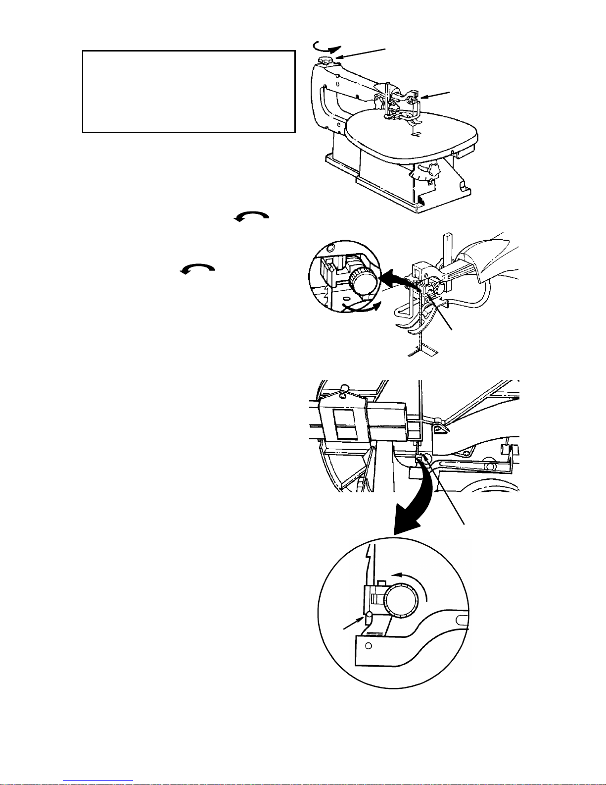
Removing Pin End Blades
WARNING
injury from accidental starting,
always turn switch "OFF" and
unplug power cord from outlet
before removing or replacing the
blade.
NOTE: Saw comes with 5" pin end blade
installed. If you are going to use 5" plain
end blades , re f er to the instructions under
“Installing Plain End Blades ”.
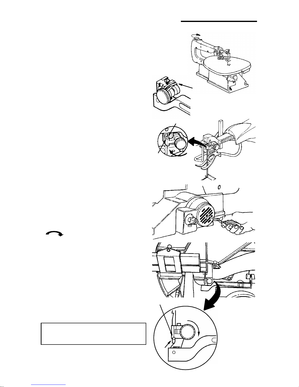
• Loosen tension on blade by turning tension knob counterclockwise at
least three full turns.
• Loosen upper and lower blade holder
knobs by turning the blade holder knobs
countercloc kwise about three full
turns. To make lower blade holder
access easier, tilt the table to 45°, and
raise the arms to the up position using a
screwdriver to rotate the motor shaft.
• Remove blade from the lower blade
holder by pushing down on the upper
arm, releasing the pin end blade from
the lower blade holder. Remove bl ade
from the upper blade holder by slightly
lifting up on the blade and pulling forward.
NOTE: The table can be tilted to 45° to
increase access and visibilit y to lower
blade holder area.
: To reduce the risk of
Tension Knob
Loosen
Blade
Upper Blade
Holder Knob
Upper
Blade
Holder
Lower Blade
Holder
Loosen
Pin
13
Alignment (Adjustments) (continued)
Installing 5" Pin End Blades
Pin end blade set up:
• Check that the blade tension knob is
loosened.
• Check that the upper and lower blade
holder knobs are loosened. Spread
blade holde r ja w s ope n usi ng fing ers.
NOTE: A rubber band looped around the
back of th e b lade h older wil l autom atica lly
open the jaws when the knobs are loosened which will make changing blades
easier.
• Install the blade through the opening in
the table with the teeth pointing down.
Engage the pin into the “V” notch of the
lower blade holder.
• Pull up on the blade and engage the
upper pin in the “V” notch of the upper
blade holder.
• Position the b l ade hol ders un til y ou a lign
the front face of the blade holders with
the vertical edge of the blade. Tighten
upper and lower blade holder knobs by
turning knobs clockwise until the jaws
close evenly against the blade.
NOTE: To prevent blade holder damage,
do not use pliers to tighten knob.
• Carefully tighten the blade tension by
turning the tension knob clockwise
just until you feel the sl ack in the
blade is removed.
• Check to see that the pins are properly
located in the V-notch slot. Turn the tension knob an additional two full turns
clockwise. This amount of blade tension
should do well for most cutting operations and blades, but may vary by up to
one turn depending on blade thickness
and blade type.
• Make sure the blade is properly
installed. Before applying power, rotate
the motor shaft by hand using a screwdriver in the motor shaft slot as shown.
Tighten
Rubber
Band
“V”-Notch
Pin
Tighten
“V”-Notch
Tighten
WARNING: To reduce the risk of
injury from thrown objects, remove
all tools from the saw.
Pin
14
Removing Plain End Blades
WARNING
injury from accidental starting,
always turn switch “OFF” and
unplug power cord from outlet
before removing or replacing the
blade.
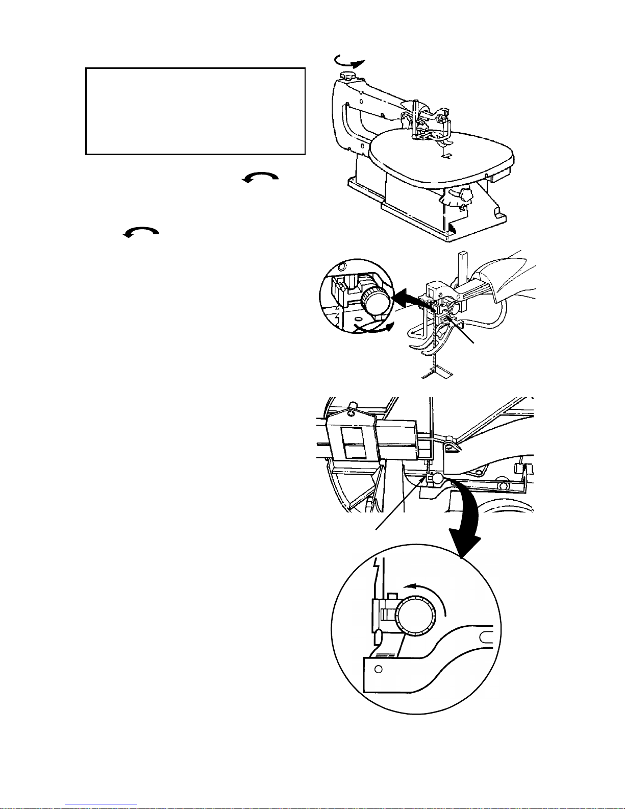
• Loosen tension on blade by turning tension knob counterclockwise at
least three full turns.
• Loosen the upper blade holder by turning the knob on the holder counterclockwise so the jaws open.
• Remove blade from upper blade holder.
• Loosen the lower blade holder knob in
the same wa y a s the uppe r blad e holder.
To make lower blade holder access easier, tilt the table to 45° and raise the
arms to the up position using a screwdriver to rotate the motor shaft.
• Remove blade from lower blade holder.
: To reduce the risk of
Loosen
Loosen
Upper
Blade
Holder
Lower Blade
Holder
Loosen
15
Alignment (Adjustments) (continued)
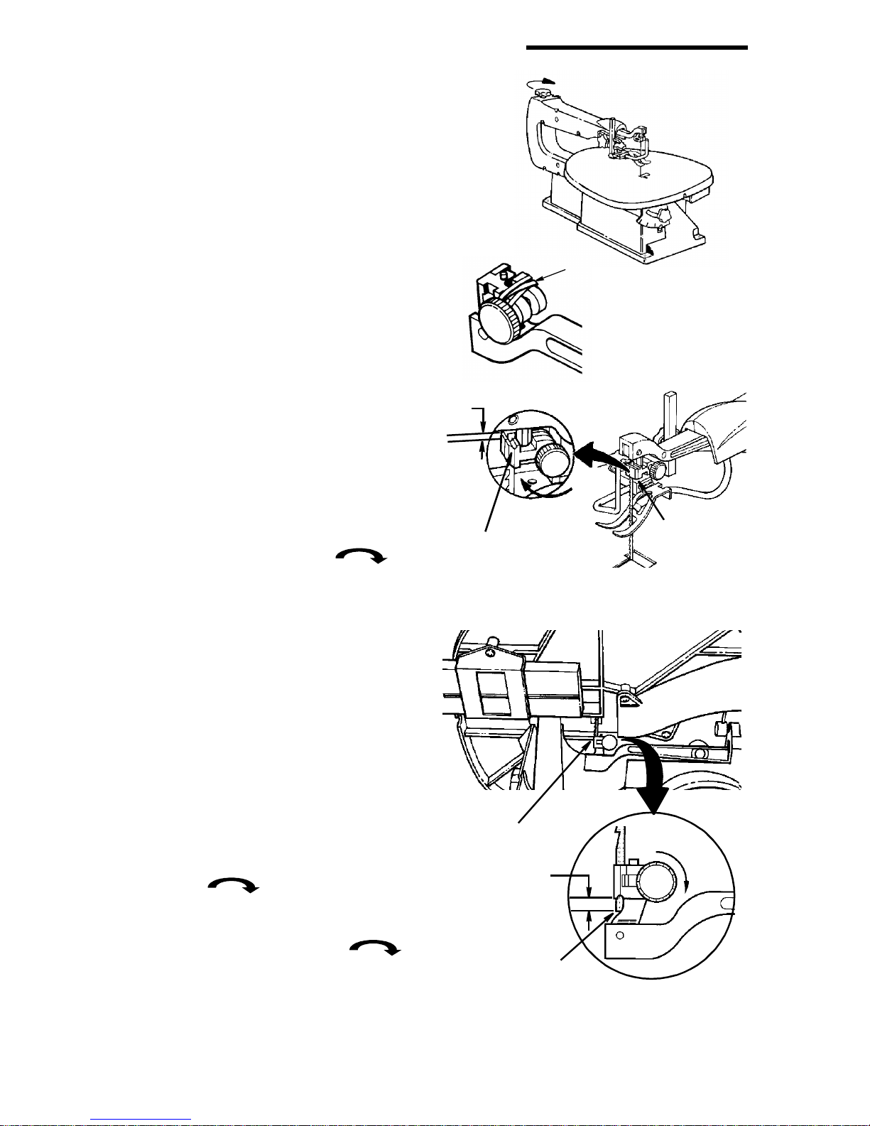
Installing 5" Plain End Blades
• Check that the blade tension knob is
loosened.
• Check that the upper and lower blade
holder knobs are loosened. Spread
blade holde r ja w s ope n usi ng fing ers.
NOTE: A rubber band looped around the
back of th e b lade h older wil l autom atica lly
open the jaws when the knobs are loosened which will make changing blades
easier.
NOTE: The table can be tilted to 45° to
increase access and visibilit y to lower
blade holder area.
• Install the blade through the hole in the
table and into the lower blade holder.
The blade tee th shoul d point down. Position the blade so that it is straight with
the front face of the blade holder and
blade end extends at least 1/8" below
the lower edge of the blade holder as
shown.
• Tighten the lower blade holder knob by
turning the knob clockwise
until the jaws close securely.
NOTE: To maintain blade holder clamping
force, keep finger knob threads cleaned
and oiled using all purpose household
machine (or motor) oil. To prevent blade
holder damage, do not use pliers to
tighten knob.
• Use the same procedure to install the
blade into the upper b lade holder . Bef ore
tightening the jaws using the upper
blade holder knob, adjust the position of
the blade, so that at least 1/8" extends
above the upper edge of the blade
holder as shown. Tighten the upper
blade holder knob by turning the knob
clockwise until the jaws close
securely.
• Carefully tighten the blade tension by turning the tension knob clockwise
until you feel the slack in the blade is
removed. Then turn the tension knob an
additional two turns. The number of turns
will be approximately two full turns, but
may vary by up to one turn depending on
blade thickness and blade type.
1/8"
Min.
Position Blade
As Shown
Lower Blade
Holder
1/8" Min.
Position Blade
As Shown
Rubber
Band
Tighten
Upper Blade
Holder
Tighten
16
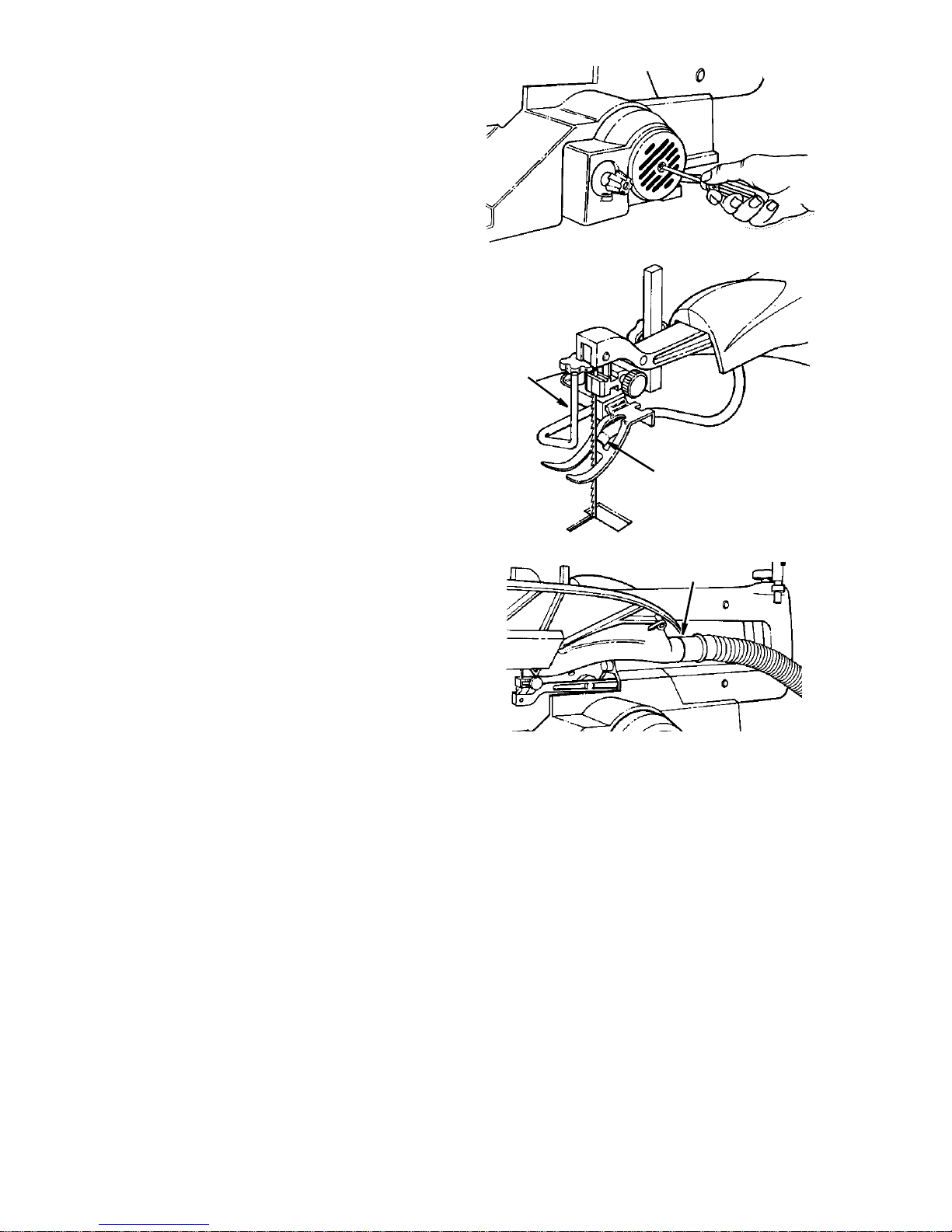
• Make sure the blade is properly
installed. Before applying power, rotate
the motor shaft by hand using a screwdriver in the motor shaft as shown.
NOTE: To prevent blade holder damage,
do not use pliers to tighten knob.
Dust Blower
The dust blower wi ll direct air to the most
effecti ve point on t he cut ting line when the
hold down is adjusted. No adjustment is
necessary to the blower.
Blade Guard
The blade guard wil l alw a ys be po sitio ned
parallel to the blade. No adjustment is
necessary .
Sawdust Collection Port
The collection port will help to control
sawdust. Simply attach a 1-1/4" wet/dry
vac hose into the opening.
Blade
Guard
Dust Blower
Sawdust Collection
Port
17

Mounting the Scroll Saw
Workbench Applications
• When mounting this saw to a w orkbench
a solid wood bench is preferred. A plywood bench will cause noise and vibration to be more noticeable.
• Hardware to mount this saw to a workbench is not supplied with the saw.
However, we recommend the hardware
used be not smaller than the following.
Description Qty.
Hex Head Screw,
1/4-20 x length required .................4
Flat Washers, 1/4 I.D. .................. ..... ..8
Lock Washers, 1/4 I.D.........................4
Hex Nuts, 1/4-20................................. 8
• A soft foam pad to place between your
scroll saw and workbench is not supplied with the saw. However, we highly
recommend the use of such a pad to
reduce noise and vibration.
Description Qty.
Soft foam pad such as carpet
padding, 24” x 12” x 1/2”..................1
Do NOT over tighten mounting bolts leave some cushion in the foam pad for
absorbing noise and vibration.
NOTE: Through normal use sawdust
accumulates under the unit. Frequently
clean sawdust from under the unit to prevent the linkage from bin ding, whic h could
overload and damage the motor.
Scroll Saw Base
Hex Head Screw
Workbench
Hex Head
Screw
Flat Washer
1/2" Foam Pad
(Optional)
Workbench
Flat Washer
Lockwasher
Top View
Side View
Hex Nut
Jam Nut
18

Safety Instructions for Basic Saw Operations
Before Each Use
Inspect your saw.
Disconnect The Saw. To reduce the risk
of injury from accidental starting, turn the
switch “OFF”, unplug the saw before
changing the setup, removing covers,
guards or blade.
Check Damaged Parts. Check for:
• Ali gnment of moving parts.
• Binding of moving parts.
• Broken parts.
• Stable mounting.
• Any other conditions that may affect the
way the saw works.
• If any part is missing, bent or broken in
any way, or any electrical part doesn’t
work properly, turn the saw off and
unplug the saw. Replace damaged,
missing or failed parts before using the
saw again. Keep Guard In Place and in
workin g order.
Maintain Tools With Care. Keep the sa w
clean for best and safest performance.
Follow instructions for lubricating.
• Use Only Recommended Accesso-
ries. Follow the instructions that come
with the accessor ies. The use of
improper accessories may cause risk of
injury to persons.
• Choose the right si z e a nd style bl ade for
the material and the type of cutting you
plan to do.
• Make s ure the blade teeth point down-
ward, toward the table.
• Make sure the blade tension is properly
adjusted.
• Keep Work Area Clean. Clu ttered areas
and benches invite accidents. Floor
must not be slippery.
To reduce the risk of burns or other fire
damage, never use the saw near flammable liquids, vapors or gases.
• Know Your Saw. Read and understand
the owners manual and labels affixed to
the tool. Lear n its appl ication s and limitations as well as the specific potential
hazards peculiar to this tool.
• To reduce the risk of inju ry from a ccide ntal contact with moving parts, don't do
layout, assembly or setup work on the
saw while any parts are moving.
• Reduce the Risk of Accidental Start-
ing. Make sure switch is “OFF” before
plugging saw into a power outlet.
Plan your work.
• Use The Right Tool. Don't force tool or
attachment to do a job it was not
designed to do.
• Use this scroll saw to cut only wood,
wood-like products, plastics and nonferrous metals.
CAUTION: This saw is NOT
designed for cutting ferrous metals
like iron or steel. When cutting nonferrous metals (brass, copper and
aluminum, etc.), metal sha vings ca n
react with wood dust and start a fire.
To reduce the risk of fire:
• Remove all traces of wood dust
from inside the saw.
• Remove all traces of metal dust
from on or around the saw before
sawing wood again.
Plan Ahead To Protect Your Eyes, Hands, Face And Ears
Any power saw can throw foreign objects
into the eyes. This can cause permanent
eye damage. Wear safety goggles, not
glasses complying with ANSI Z87.1 (or in
Canada CSA Z94.3-99) shown on package. Everyday eyeglasses have only
impact resistant lenses. They are not
safety glasses. Safety goggles are available at many local retail stores. Glasses
or goggles not in compli ance with AN SI or
CSA could seriously hurt you when they
break.
19

Safety Instructions for Basic Saw Operations (continued)
Dress for safety
• Do not wear loose clothing, gloves,
neckties or je welry (rings, wristw atches).
They can get caught and draw you into
moving parts.
• Wear non-slip footwear.
• Tie back long hair.
• Rol l long sleeves above the elbow.
• Noise levels vary widely. To reduce the
risk of possible hearing damage, wear
ear plugs or muffs when using saw for
hours at a time.
• For dusty operations, wear a dust mask
along with the safety goggles.
Inspect your workpiece.
Make s ure ther e are no n ails or foreign
objects in the part of the workpiece to be cut.
Use extra caution with large, very
small or awkward workpieces
• Never use this tool to finish pieces too
small to hold by hand.
• Use extra supports (tables, saw horses,
blocks, etc.) for any workpiece large
enough to tip when no t hel d down to the
table top.
• Never use another person as a substitute for a table extension, or as additional support for a workpiece or to help
feed, support or pull the workpiece.
• When cutting irregularly shaped workpieces, pl an y our w ork so it wil l not pin ch
the blade. A piece of molding, for example, must lay flat or be held by a fixture
or jig that will not let it twist, rock or slip
while being cut.
• Properly support round material such as
dowel rods or tubing. They have a tendency to roll during a cut, causing the
blade to "bite". To avoid this, always use
a "V" block.
• Clear everything except the workpiece
and related su pport devices off the tab le
before turning the saw on.
Plan the way you will hold the workpiece from start to finish.
• Do not hand hold pieces so small that
your fingers will go under the blade
guard. Keep your hands away from the
blade.
• R educe th e Risk of awkward operations
and hand positions where a sudden slip
could cause fi ngers or h and to mo v e into
the blade.
• Don’t Overreach. Keep good footing
and balance.
• Keep your face and body to one side of
blade, out of line with a possible thrown
piece if the blade shou ld brea k.
Whenever Saw Is Running
WARNING
(gained from frequent use of your
saw) cause a careless mistake. A
careless fraction of a second is
enough to cause a severe injury.
• Before starting your cut, watch the saw
while it runs. If it makes an unfamiliar
noise or vibrates a lot, s top i mm ed iat ely.
Turn the saw off. Unpl ug the saw. Do not
restart until finding and correcting the
problem.
• Keep Children Awa y. Keep all vis itors a
safe distance from the saw. Make sure
bystanders are clear of the saw and
workpiece.
• Don’t Force Tool. It will do the job better
and safer at its designed rate. Feed the
workpi ece into the saw blade only fast
enough to le t it cut w ithout bogg ing dow n
or binding.
: Don’t let familiarity
Before freeing any jammed material:
• Turn switch “OFF”.
• Wait for all moving parts to stop.
• Unplug saw.
When backing up the workpiece, the
blade may bind in the kerf (cut). T his is
usually caused by sawdust clogging
up the kerf. If this happens:
• Turn switch “OFF”.
• Wait for all moving parts to stop.
• Unplug saw.
• With a flat blade screwdriver, turn the
motor by hand while backing up the
workpiece.
Before remo ving loose piec es from the
table, turn saw off and wait for all moving parts to stop.
20

Before Leaving The Saw
• Wait for all moving parts to stop.
• Make Workshop Child-proof. Unplug
the saw. Lock the workshop and ON/
Basic Saw Operations
General Instructions
Please, read and understand the follow-
ing items about y our sc roll sa w before
attempting to use the saw.
• The saw does not c ut wood b y itself . You
allow the s aw to cut woo d b y guidi ng the
wood into the blade as it moves.
• The blade teeth cut wood only on the
down stroke.
• You must guide the wood into the blade
slowly because the teeth of the blade
are very small and the y can onl y remov e
wood when they are on the down stroke.
• There is a learning curve for each person who wants to use this saw. During
that period of time it is expected that
some blades will break until you learn
how to use the saw and receive the
greatest benefit from the blades.
• Best results are achieved when cutting
wood less than one inch thick.
• When cutting wood thic ke r than one inch
the user must guide the wood very, very
slowly int o th e blade and take extra care
not to bend or twist the blade while cutting in order to maximize blade life.
• Teeth on scroll saw blades wear out and
as such must be replaced frequently for
best cutting results. Scroll saw blades
generally stay sharp for 1/2 hour to 2
hours of cutting.
OFF knob on the saw. Store the key
away from children and others not qualified to use the tool.
• To get accurate cuts, be prepared to
compensate for blade’s tendency to follow the wood grain as you are cutting.
• This scroll saw is intended to cut wood,
wood-like products, plastics and nonferrous metals.
• When choosing a blade to use with your
scroll saw, consider the following carefully.
• Very fine, narrow blades should be
used to sc ro l l cu t in thi n wo od 1/ 4 in ch
thick or less.
• To cut wood over 1/4 inch thick, use
wider blades.
• Most blade packages state the size or
thickness of wo od which that blade is
intended to cut, and the radius, size of
curve, which can be cut with that
blade.
• Wi der blades can’t cut cur ves as tight
or small as thinner blades.
• Narrower blades work well only on
thinner wood material.
• This saw uses 5 inch long pin and plain
end type blades only.
• Blades wear faster when cutting plywood, which is very abra si ve, when sawing wood which is thicker than the 7/8
inch blade stroke, and when sawing
hardwood, or when side pressure is
placed on the blade.
Making Interior Scroll Cuts
• One of the features of this saw is that it
can be used to make scroll cuts on the
interior of a board without breaking or
cutting into the outline or perimeter of
the board.
WARNING: To reduce the risk of
injury from accidental starting,
always turn switch "OFF" and
remove plug from power so urce outlet before removing or replacing the
blade.
• T o make interior cuts in a board, remove
the scroll saw blade as explained in the
Assembly section.
• Drill a 1/4" or larger hole in the board in
which you will make interior cuts.
• Place the board on the saw table with
the hole in the board over the access
hole in the table.
• Install the blade through the hole in the
board and adjust blade tension.
21
Basic Saw Operations (continued)
• When finished making the interior scroll
cuts, simply remove the blade from the
blade holders, as described in the
Assembl y section, and remove the board
from the table.
Choice of Blade and Speed
Install Blade Through
Hole In Board
Your scroll saw accepts a wide variety of
5" plain end and pi n end b lades . As a gen eral guide:
• Use a finer tooth blade for cutting thin
workpieces, when a smoother cut is
required for hard materials or when
using slow saw speeds.
• Use a coarser tooth blade for cutting
thicker workpieces, when making
straight cuts, for medium to soft materi-
Pin and Plain end Blades
Teeth/
Inch
20
15
12.5 .038" .016" 600-
11.5
10
Width Thickness Speed Application
.029"
.110"
.053"
.110"
.012"
.018"
.018"
.018"
500-600 Tight radius work; 3/32" to 1/8" wood
1200
12001700
als or when using faster saw speeds.
• Use a blade that will hav e at least 2 teeth
in the material at all times.
• Use thin, narrow blades for tight radius
work, and thick, wide blades for large
curves and straight cuts.
Listed below are examples of some
blades and their intended uses:
veneer, wood, bone, fiber, plastics,
non-ferro us me tals, etc.
Close radius cuttin g in materials 3/32" to
1/2" thick. Good f or hard and s oft wood,
bone, horn, plastics , etc.
For hard and s oft woods and wo odlike
products
3/16" and up.
22
Maintenance
WARNING: For your own safety,
push control knob “OFF” and
remove plug from power so urce outlet before mainta ining or lu brica ting
your saw.
General
An occasional coat of paste wax on the
work tab le will allo w the wood be ing cut to
glide smoothly across the work surface.
Drawer - Apply oil safe for plastic to
drawer and guide as necessary.
To maintain blade holder clamping force,
keep finger knob threads cleaned and
oiled using all purpose household
machine (or motor) oil.
Motor/Electrical
The motor bearings are permanently
lubricated and require no further lubrication.
Do not attempt to oil the moto r bearings or
service the motor internal parts.
Drawer
Oil Finger
Knob Threads
Oil
Here
WARNING: If the power cord is
worn, cut or damaged in any way,
have it replaced immediately.
WARNING: To reduce the risk of
fire or electrocution, reassemble
electric parts with only approved
service parts. Reassemble exactly
as originally assemb led.
Arm Bearings
Lubricate the arm bearings after 10 hours
of use. Re-oil after every 50 hours of use
or whenever there is a squeak coming
from the bearings.
• Turn saw on its side.
• Squirt a generous amount of SAE 30 oil
or household machine oil around the
shaft end and bronze bearing.
• Let the oil soak in overnight in this position.
• Next day repeat the above procedure for
the opposite side of the saw.
Arm
Bearing
Arm
Bearing
23

Troubleshooting
WARNING: For your own safety, turn switch “OFF”, and remove plug from
power source outlet before troubleshooting your scroll saw.
Problem Probable Cause Remedy Schedule
Breaking
Blades.
Plain end
blade slips
within blade
clamp
Motor will not
run.
1. Wrong tension
2. Over working blade.
3. Wrong blade application.
4. Twis ting blade in wood.
1. Blade clamp not tightened
2. Dirty finger knob
threads.
1. Damaged cord or plug.
2. Damaged motor or control board.
1. Adjust blad e tensio n per inst ruction s
under installing Pin End (Plain End)
Blades.
2. Reduce feed rate.
3. Use narrow blades for cutting thin
wood, wide blades for thicker wood.
4. Avoid side pressure on blade.
1. Tighten blade clamp.
2. Clean and oil threads.
3. Check position of blade in holder - 1/8"
beyond top and at front end of blade
holder.
1. Replace damaged parts before
using saw again.
2. Consult Authorized Service. Any
attempt to repai r this motor or c ontrol
board may create a HAZARD unless
repair is done by a qualified service
technician.
Vibration
NOTE: There
will always be
some vibration
present when
the saw is running because
of the blade
and arm
movement.
1. Improper mounting of
the saw.
2. Unsuitable mounting
surface.
3. Loose table
4. Loose motor mounting.
5. Resonance
1. See mounting instructions in this
manual for proper mounting technique.
2. The heavier your workbench is, the
less vibrat ion will occur. A plywood
workbench will not be as good a
work surface as the same size solid
lumber. Use common sense in
choosing a mounting surface.
3. Tighten table lock knob.
4. Tighten motor mounting screws.
5. Try different speed.
24

Wiring Diagram
WARNING: To reduce the risk of
fire or shock, use only recommended service parts and reassemble exactly as originally assembled.
Ground
Screw
(Black)
Smooth
Jacket
Switch
Cord w/Plug
Green
Ribbed
Jacket
(White)
White
Motor
Black
Control
Board
25
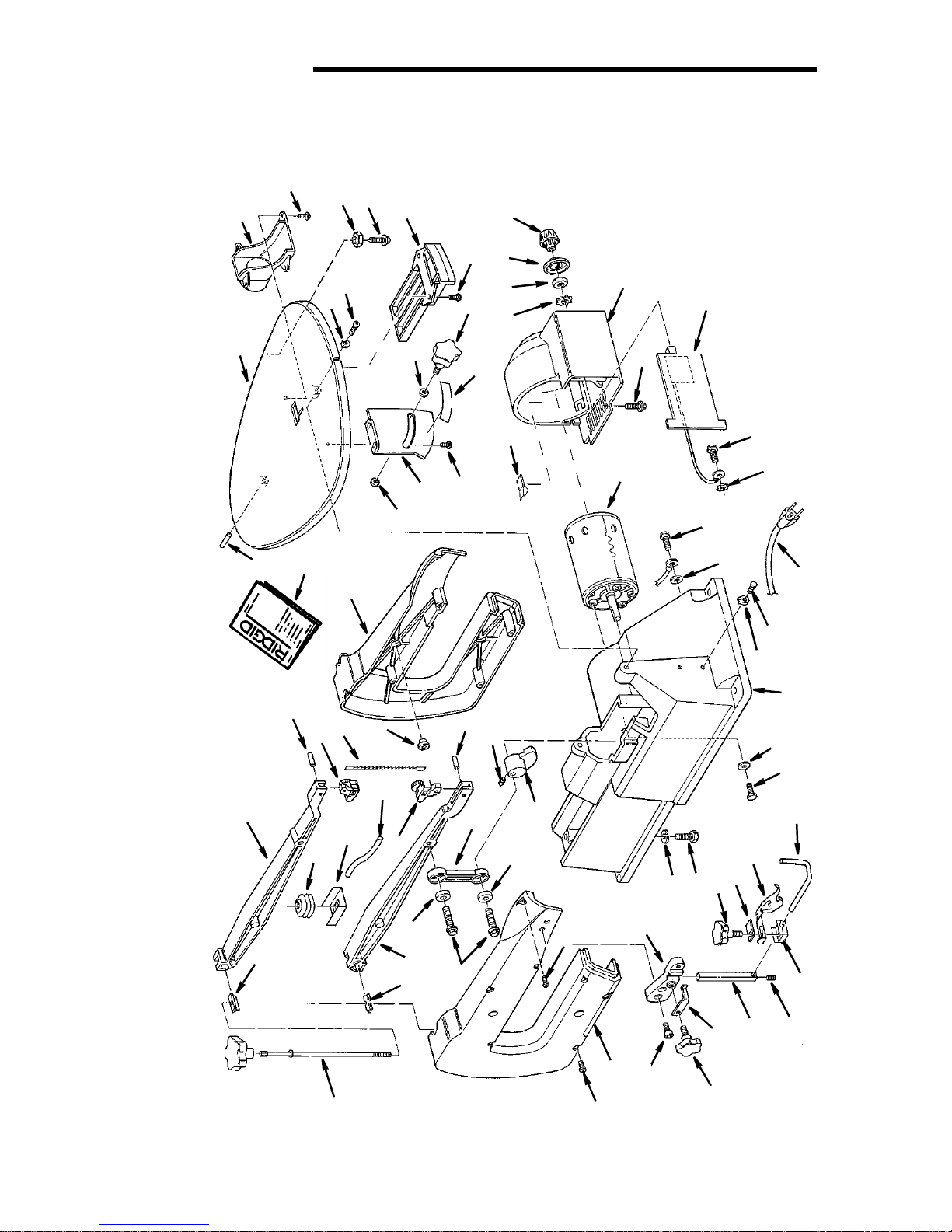
Repair Parts
RIDGID parts are available on-line at www.ridgidparts.com
3
2
1
14
63
6
7
8
5
4
9
12
13
57
15
3
16
17
10
18
11
24
3
19
25
21
20
22
23
22
23
26
27
28
34
38
29
23
30
35
36
37
Model No. SS16501
53
Parts List For RIDGID 16" Variable Speed Scroll Saw
52
54
62
55
56
51
61
58
60
59
48
49
50
54
45
48
46
44
43
42
41
40
31
32
10
10
39
33
47
7
26
 Loading...