

RIDGID OL90150 User Manual

OL90150
OPERATOR’S MANUAL
WHEELBARROW
AIR
COMPRESSOR
To reduce the risk of injury, the user
must read and understand the
Operator’s Manual before using this
product.
IN614300AV 9/04 Printed in U.S.A.
!
WARNING:

Table of Contents
Section Page
Table of Contents . . . . . . . . . . . . . . . .2
Safety Instructions . . . . . . . . . . . . . . .3
Safety Signal Words . . . . . . . . . . . . .3
Before Using the Air
Compressor . . . . . . . . . . . . . . . . . . . .3
Spraying Precautions . . . . . . . . . . . .5
Breathable Air Warning . . . . . . . . . . .5
Warning Labels . . . . . . . . . . . . . . . . .6
Motor Specifications and Electrical
Requirements . . . . . . . . . . . . . . . . . . .7
Power Supply and Motor
Specifications . . . . . . . . . . . . . . . . . .7
General Electrical Connections . . . . .7
110-120 Volt, 60 Hz Tool
Information . . . . . . . . . . . . . . . . . . . .8
Extension Cords . . . . . . . . . . . . . . . .8
Changing Motor Voltage . . . . . . . . . .9
Thermal Overload Protector . . . . . .10
Glossary of Terms . . . . . . . . . . . . . .10
Unpacking and Checking
Contents . . . . . . . . . . . . . . . . . . . . . .11
Section Page
Installation . . . . . . . . . . . . . . . . . . . . .11
Getting to Know Your Air
Compressor . . . . . . . . . . . . . . . . . . .12
Operating Your Air Compressor . . .14
Moisture in Compressed Air . . . . . .14
Lubrication . . . . . . . . . . . . . . . . . . . .14
Operating Your Air Compressor . . .15
For Trouble-Free Operation . . . . . .16
Maintenance . . . . . . . . . . . . . . . . . . .17
Tank . . . . . . . . . . . . . . . . . . . . . . . . .18
Filter Removal, Inspection, and
Replacement . . . . . . . . . . . . . . . . . .18
Drive Belt . . . . . . . . . . . . . . . . . . . . .18
Storage . . . . . . . . . . . . . . . . . . . . . .19
Maintenance Schedule . . . . . . . . . .19
Troubleshooting . . . . . . . . . . . . . . . .20
Repair Parts . . . . . . . . . . . . . . . . . . .24
Warranty . . . . . . . . . . . . . . . . . . . . . .28
2
Safety Instructions
This manual contains information that is
very important to know and understand.
This information is provided for SAFETY
and to PREVENT EQUIPMENT PROBLEMS. To help recognize this information, observe the following symbols.
Safety Signal Words
Danger indicates
an imminently hazardous situation which, if not avoided,
WILL result in death or serious injury.
Warning indicates
a potentially hazardous situation which, if not avoided,
COULD result in death or serious injury.
Caution indicates a
potentially hazardous situation which, if not avoided,
MAY result in minor or moderate injury.
Notice indicates
important information, that if not followed, may cause damage to equipment.
Since air compressors and other components (material pump, spray gun, filters,
lubrications, hoses, etc.) used make up a
high pressure pumping system, the following safety precautions should be
observed at all times. Only persons well
acquainted with these rules of safe operation should be allowed to use the air
compressor.
1. Read instruction manuals for each
component carefully, before attempting to assemble, disassemble or
operate your particular system.
2. Wear safety glasses (meeting ANSI
Z87.1 or in Canada CSA Z94.3-99)
and use hearing protection when
operating the pump or unit. Everyday
glasses are not safety glasses.
3. Do not exceed pressure rating of any
component in system.
4. Protect material lines and air lines
from damage or puncture. Keep hose
and power cable away from sharp
objects, chemical spills, oil, solvents,
and wet floors.
5. Never point a spray gun at oneself or
any other person. Accidental discharge may result in serious injury.
6. Check hoses for weak or worn condition before each use, making certain
all connections are secure; do not
use if deficiency is found. Notify an
authorized service facility for examination or repair.
7. Release all pressures within system
slowly; dust and debris may be harmful.
Before Using the Air Compressor
All electrical work should be
done by a qualified (licensed or
certified) electrician. On a properly wired circuit, the black
wires supply a voltage potential
even when the unit is off.
Disconnect power and depressurize system before servicing
air compressor! (Turn pressure
regulator knob fully clockwise
after shutting off compressor.)
3
!
WARNING:
!
CAUTION:
!
DANGER:
!
WARNING:
NOTICE:
!
WARNING:

8. Follow all local electrical and safety
codes, as well as the National
Electrical Code (NEC) and the
Occupational Safety and Health Act
(OSHA).
9. Wiring and fuses should follow electrical codes, current capacity, and be
properly grounded.
10. Electric motors must be securely and
adequately grounded. See grounding
instructions and extension cord information in this manual.
11. Always disconnect power source
before working on or near a motor, or
its connected load. If power disconnect point is out-of-sight, lock it in the
open position and tag to prevent
unexpected application of power.
12. Guard all moving parts; keep visitors
away. Never allow children in work
area.
13. Use only a properly grounded outlet
that will accept a three pronged plug,
and wear shoes to prevent shock
hazards.
14. Be careful when touching exterior of
operating motor; it may be hot
enough to cause injury.
15. Protect power cable from coming in
contact with sharp objects.
16. Clean electrical or electronic equipment with an approved cleaning
agent, such as dry, nonflammable
cleaning solvent.
17. To avoid spontaneous combustion,
discard waste rags into approved
metal waste cans.
18. Never store flammable liquids or
gases in vicinity of compressor.
19. When spraying with solvent or toxic
chemicals, follow instructions provided by the chemical manufacturer.
20. Spray in a well ventilated area, to
keep fumes from collecting and causing health and fire hazards.
21. Do not spray in vicinity of open
flames or other places where a spark
can cause ignition. Do not smoke
when spraying paint, insecticides, or
other flammable substances.
22. Use a respirator when spraying.
23. NEVER reset safety valve or pressure switch. Keep safety valve free
from paint and other accumulations.
This provides safety against over
pressure.
24. Do regular maintenance; keep all
nuts, bolts, and screws tight, to be
sure equipment is in safe working
condition .
25. Keep cleaning rags and other flammable waste materials in a tightly
closed metal container and dispose of
later in the proper fashion.
26. Drain tanks of moisture after each
day’s use. If unit will not be used for a
while, it is best to leave drain cock
open until such time as it is to be
used. This will allow moisture to completely drain out and help prevent
corrosion of inside of tank.
27. Inspect tank yearly for rust, pin holes
or any other imperfections that could
cause it to become unsafe. NEVER
weld or drill holes in air tank.
28. Do not wear loose clothing or jewelry
that will get caught in the moving
parts of the unit.
Safety Instructions (continued)
4
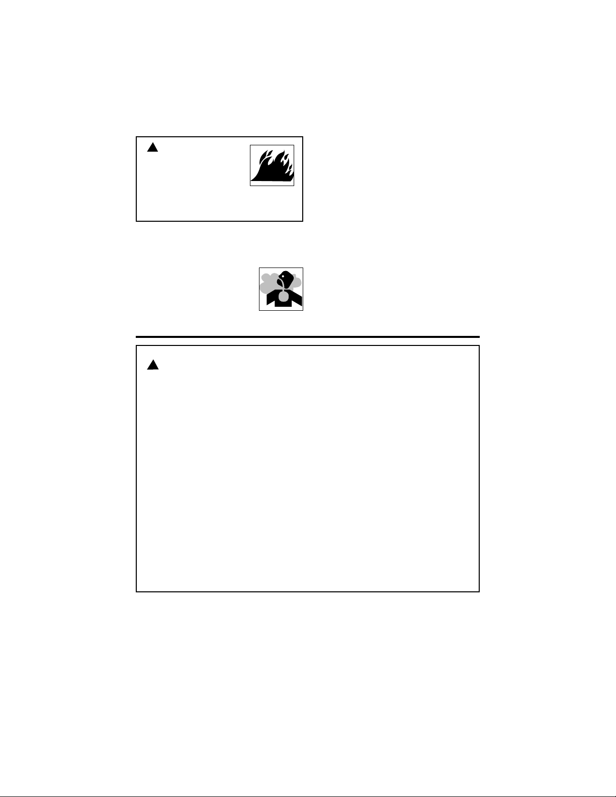
1. Do not smoke when spraying paint,
insecticides, or other flammable substances.
2. Use a face mask/respirator when spraying and
spray in a well ventilated
area to prevent health and
fire hazards.
3. Do not direct paint or other sprayed
material at the compressor. Locate
compressor as far away from the
spraying area as possible to minimize
overspray accumulation on the compressor.
4. When spraying or cleaning with solvents or toxic chemicals, follow the
instructions provided by the chemical
manufacturer.
5
Spraying Precautions
Do not spray flammable materials in vicinity of open flame or
near ignition sources including
the compressor unit.
!
Breathable Air Warning
This compressor/pump is not equipped and should not be used “as
is” to supply breathing quality air. For any application of air for
human consumption, the air compressor/pump will need to be fitted
with suitable in-line safety and alarm equipment. This additional
equipment is necessary to properly filter and purify the air to meet
minimal specifications for Grade D breathing as described in
Compressed Gas Association Commodity Specification G 7.1 - 1966,
OSHA 29 CFR 1910. 134, and/or Canadian Standards Associations
(CSA).
DISCLAIMER OF WARRANTIES
In the event the compressor is used for the purpose of breathing air
application and proper in-line safety and alarm equipment is not
simultaneously used, existing warranties shall be voided, and
Campbell Hausfeld disclaims any liability whatsoever for any loss,
personal injury or damage.
WARNING:
!
DANGER:
Safety Instructions (continued)
6
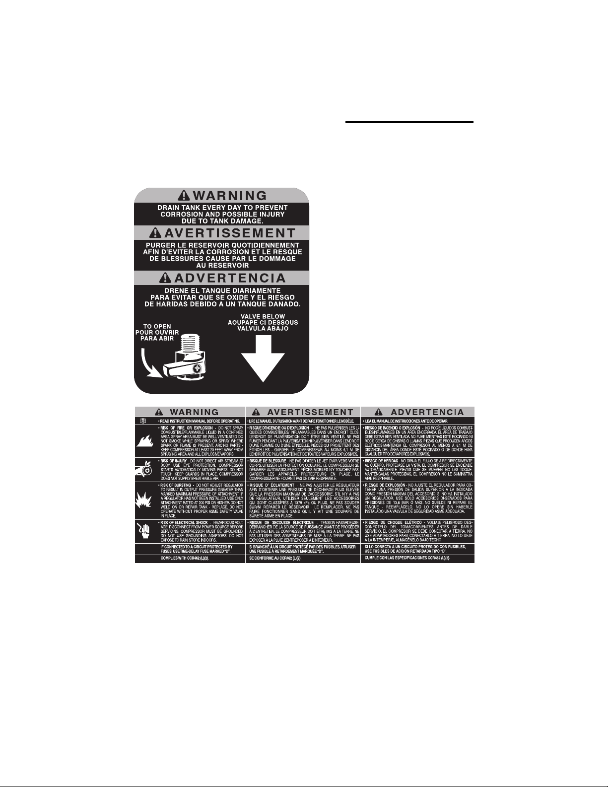
Find and read all warning labels found on
the air compressor shown below
Warning Labels
0
DK724100AV 100
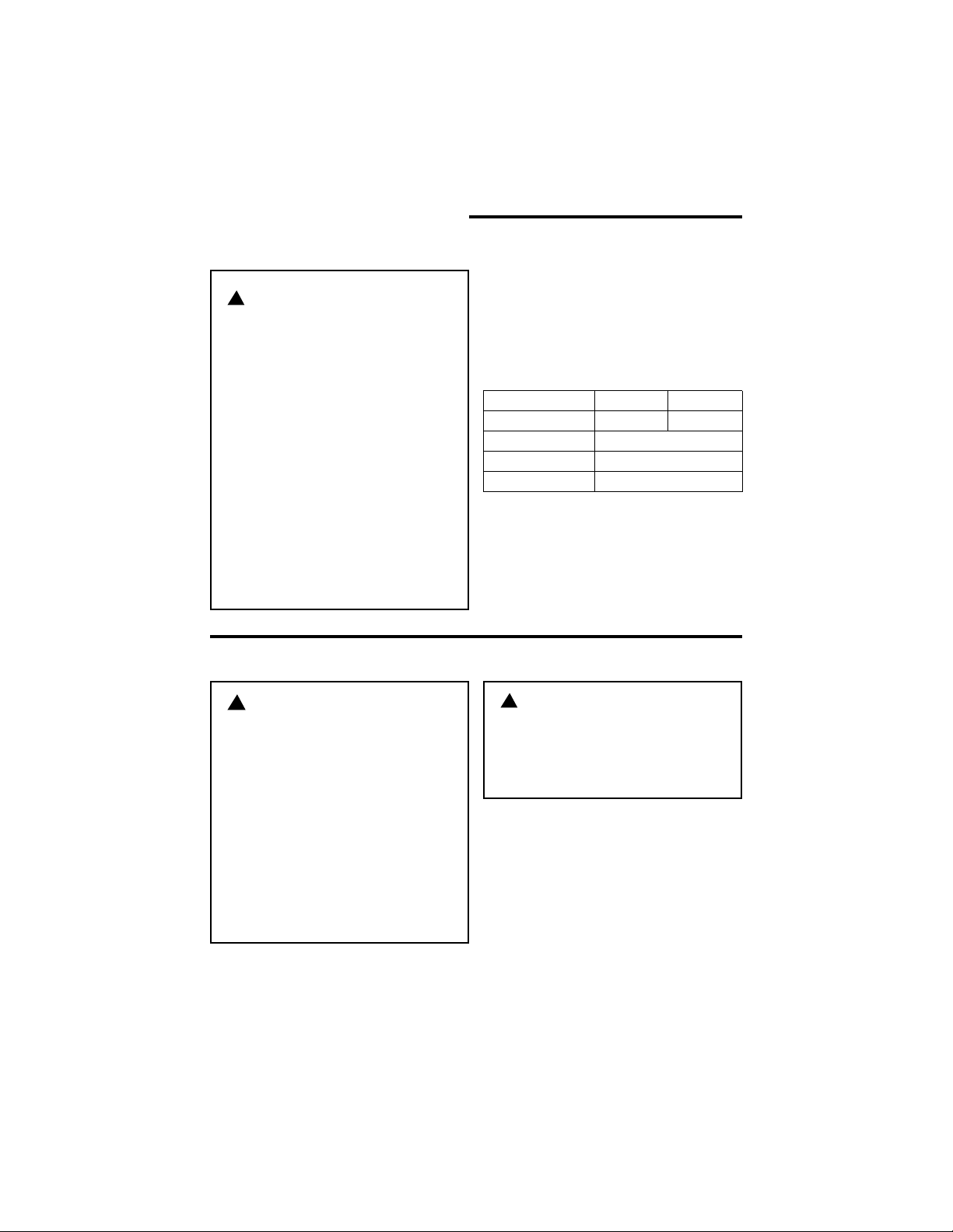
The A-C motor used on this compressor
is a capacitor start, capacitor run nonreversible induction type, having the following specifications. It is wired at the
factory for operation on 110V-120V AC,
60 Hz service.
Voltage 110-120 220-240
Amperes 15.0 7.5
Hertz (Cycles) 60
Phase Single
RPM 3450
Motor Specifications and
Electrical Requirements
7
Power Supply and Motor Specifications
To reduce the risk of electrical
hazards, fire hazards or damage
to the tool, use proper circuit
protection. Your tool is wired at
the factory for operation using
the voltage shown. Connect
tool to a power line with the
appropriate voltage and a 15amp branch circuit. Use a 15amp time delay type fuse or circuit breaker.To reduce the risk
of shock or fire, if power cord is
worn or cut, or damaged in any
way, have it replaced immediately.
!
General Electrical Connections
To reduce the risk of electrocution:
1. Use only identical replacement parts when servicing.
Servicing should be performed by a qualified technician.
2. Do not use in rain or where
floor is wet. This tool is
intended for indoor residential use only.
Do not permit fingers to touch
the terminals of plug when
installing or removing the plug
to or from the outlet.
WARNING:
!
DANGER:
!
WARNING:
8
The plug supplied on your tool may not
fit into the outlet you are planning to use.
Your local electrical code may require
slightly different power cord plug connections. If these differences exist refer to
and make the proper adjustments per
you local code before your tool is
plugged in and turned on.
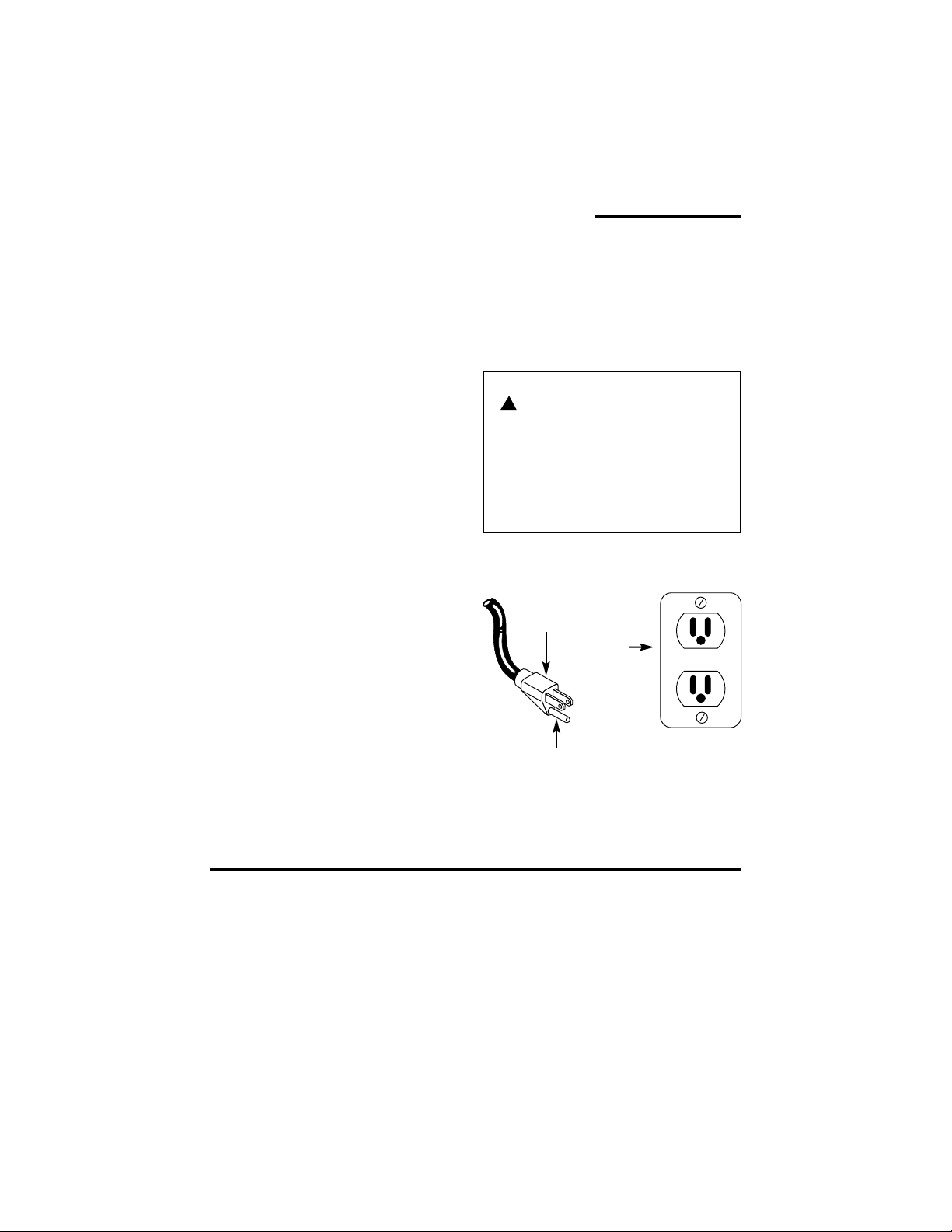
In the event of a malfunction or breakdown, grounding provides a path of least
resistance for electrical current to reduce
the risk of electric shock. This tool is
equipped with an electric cord having an
equipment-grounding conductor and a
grounding plug, as shown. The plug must
be plugged into a matching outlet that is
properly installed and grounded in accordance with all local codes and ordinances.
Do not modify the plug provided. If it will
not fit the outlet, have the proper outlet
installed by a qualified electrician.
Improper connection of the equipmentgrounding conductor can result in a risk
of electric shock. The conductor with
insulation having an outer surface that is
green with or without yellow stripes is the
equipment-grounding conductor. If repair
or replacement of the electric cord or
plug is necessary, do not connect the
equipment-grounding conductor to a live
terminal.
If the grounding instructions are not completely understood, or if you are in doubt
as to whether the tool is properly grounded check with a qualified electrician or
service personnel.
Motor Specifications and
Electrical Requirements (continued)
110-120 volt, 60Hz Tool Information
If not properly grounded, this
tool can cause an electrical
shock, particularly when used
in damp locations, in proximity
of plumbing, or out of doors.
Grounding Prong
3-Prong Plug
Properly
Grounded
3-Prong
Outlet
Extension Cords
1. The air compressor should be located
where it can be directly plugged into
an outlet. An extension cord should
not be used with this unit.
2. To avoid loss of power and overheating, additional air hose must be used
to reach work area instead of extension cords.
!
WARNING:
TEST
RESET
9
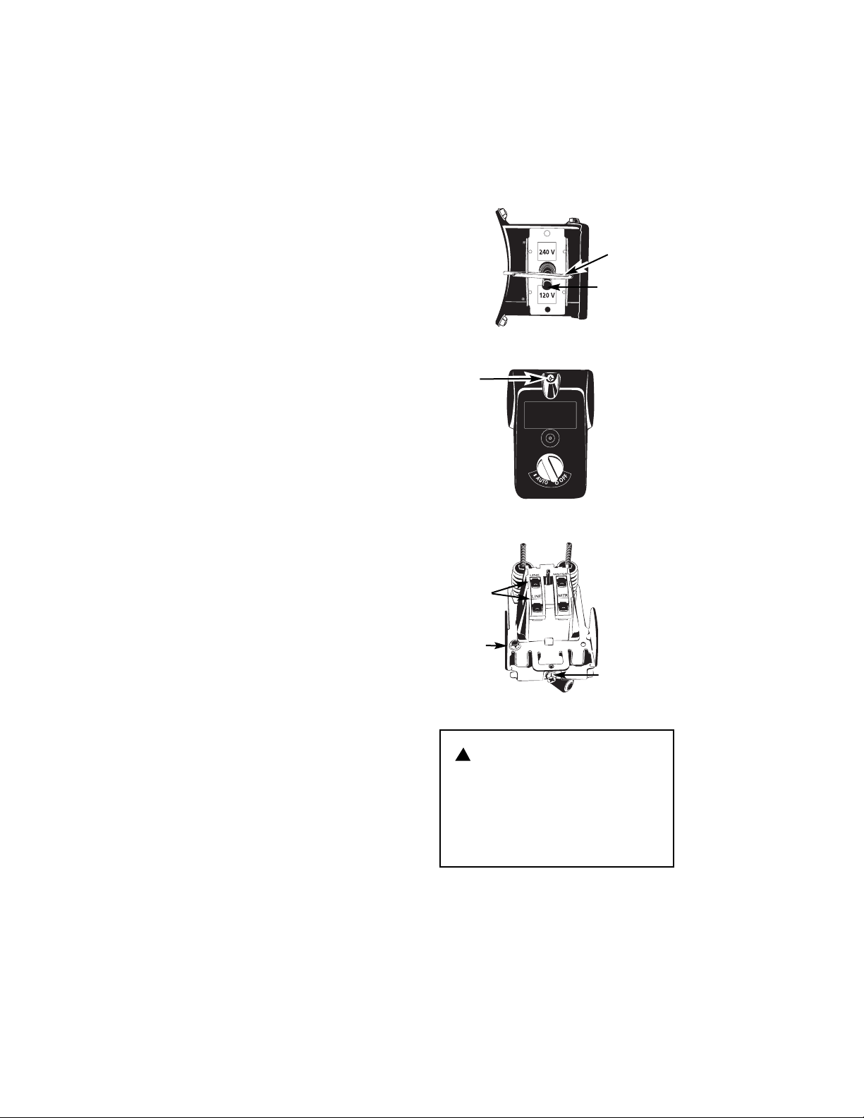
NOTE: The motor is prewired at the factory for 120V operation. Use the following procedure to change motor voltage to
240V.
1. Unplug the power cord before making
or modifying connections.
2. Remove the hitch pin.
3. Toggle the motor voltage selector
switch from 120V to 240V.
4. Install the hitch pin.
5. Unscrew the pressure switch cover
retaining screw and remove the pressure switch cover.
6. Remove the black and white wires
labeled ‘line’ and the green ground
wire. Loosen the screw for the strain
relief.
7. Install a 3 wire, 240 volt, 15 amp U.L.
listed cord (not provided). Be sure to
connect the white and black wires to
the terminals labeled ‘line’ and the
green ground wire to the ground terminal. Also tighten the strain relief
screw.
8. Install the pressure switch cover and
fasten the pressure switch cover
retaining screw.
The unit is now ready for 240 Volt operation.
Changing Motor Voltage
If not properly grounded, this
tool can cause an electrical
shock, particularly when used
in damp locations, in proximity
of plumbing, or out of doors.
Hitch pin
Motor
voltage
selector
switch
Line
terminals
Ground
terminal
Strain relief
screw
Pressure Switch
Pressure Switch Cover
Retaining
screw
!
WARNING:
 Loading...