

RIDGID MS 1290 Owner's Manual

MS1290
OWNERS MANUAL
For Your Safety:
Read all instructions carefully
Save this manual for future
referenece
12 INCH DUAL BEVEL
SLIDE COMPOUND
MITER SAW
Part No. SP6463 Printed in Taiwan

Table of Contents
Section Page
Ta ble of Cont ents ...........................................2
Safety Instructions For Miter Saw ................3
Safety Signal Words ....................................3
Before Usi ng The Saw ..... .... ... .... .... .............3
When Installing Or Moving The Miter Saw ....4
Before Each Use .............................. ..............4
T o Reduce the Risk of Injury From Jams, Slips
Or Thrown Pieces ........................................5
Plan Ahead To Protect Y our Eyes, Hands, Face
and Ears ......................................................5
Dress For Safety ............................................6
Preparing to Make Cut ...................................6
Plan The Way You Will Hold The Workpiece
From Start To Finish. ...................................7
Whenever Saw Is Running ............................7
Before Leaving The Saw ...............................8
Glossary of Terms for Woodworking ...........8
Motor Specifications and Electrical Require-
ments ..........................................................9
Power Supply and Motor Specifications ......9
General Electrical Connections ...................9
110-120 Volt, 60 Hz. Tool Information .........9
Motor Saf ety P rote ctio n ... .... ... .... .... ...........10
Wire Sizes ..................................................10
Unpacking and Checking Contents ............11
Tools Needed ............................................11
Unpac king ..... ........... ........ ........... ............ ...11
List of Loose Parts .....................................11
Getting to Know Y our Miter Saw .................12
Assembly .......................................................13
Installing or Removing the Blade ...............13
Assembling Dust Bag ..................................15
Workpiece Clamp Installation ....................15
Four Basic Saw Controls .............................15
Alignment (Adjustments) .............................17
Miter Lo ck Lever Ad jus tm e nt ...... ...............20
Bevel Lock Lever Adjustment ....................20
Bevel Pivot Movement/Adjustment ............21
Mounting The Miter Saw ..............................22
Safety Instructions for Basic Saw
Opera tion s . .............................................23
Before Each Use .............................. ............23
T o Reduce the Risk of Injury From Jams, Slips
Or Thrown Pieces ......................................23
Plan A head To Pr otect Your Eyes , H ands,
Face and Ears ....... .... .... .... ......................24
Section Page
Dress For Safety ..........................................24
Preparing to Make the Cut ...........................25
Whenever Saw Is Running ................ ..........26
Before Leaving The Saw: ............................26
Basic Saw Operations ..................................27
Making Common Slide Compound Cuts ... 27
Slide Cutting ............................................. 27
Chop Cutting ............................................. 28
Body and Hand Pos it ion ... .... .... ... .... ......... 28
Miter Cut ................................................... 29
Miter Scale Usage ..................................... 29
Bevel Cut .................................................. 29
Sliding Fence ............................................ 29
Vernier Bevel Scale Operation: ................ 29
Compoun d Cut ... .... ... ................................ 30
Cutting Compound Miters on Picture Frames
and Boxes ............................................... 30
Cutting Bowed Material ............................. 30
Workpiece Clamp Usage .......................... 31
Workpiece Support ................................... 32
Auxiliary Fe nc e ...... ... .... ............................ 32
Rough Cutting A Dado .............................. 33
Helpful Hints When Cutting Compound
Miters ... ............ ........... ............ ........... ..... 3 3
Cutting Base Moldings .............................. 33
Cutting Crown Moldings ............................ 34
Two Methods of Cutting Crown Molding ... 34
Maintenance and Lubrication .....................38
Maintenance ............................................. 38
Lubrication ................................................ 39
Motor Belt Tension .................................... 39
Accessories ..................................................40
Recommen de d Ac cess o rie s ........ .... ......... 40
Basic Blade Requirements ....................... 40
Prohibited Accessories ................................40
Using Carbide Tipped Blades .....................40
Tr oubleshooting Guide ................................41
General .. ................................................... 41
Motor .. .... .... ............................................... 42
Wiring Diagram .............................................42
Troub le Shootin g of Br ak e by Qualified Ser -
vice Person Only .................................... 42
Notes ..............................................................43
Repair Parts ...................................................44
Notes ..............................................................50
2
Safety Instructions For Miter Saw
Safety is a combination of common sense, staying alert and knowing how
your miter saw works. Read this manual to understand this miter saw.
Safety Signal Words
DANGER: means if the safety infor-
mation is not followed someone will
be seriously injured or killed.
Before Using The Saw
WARNING: Some dust created by
power sa ndin g, s awi ng, gri ndi ng,
drilling, and other construction
activities contains chemicals
known (to the State of California)
to cause cancer, birth defects or
other rep r od uc ti v e harm. Some
examples of these chemicals are:
• Lead from lead-based paints,
• Crystalline silica from bricks
and cement and other mason ry
products, and
• Arsenic and chromium from
chemically-treate d lumber.
Y o ur risk from these exposures
varies , depending on how often
you do th is type of work. To
reduce your exposure to these
chemicals: work in a well ventilated area, and work with
approved safety equipment,
such as those dust masks that
are specially designed to filter
out microscopic particles.
WARNING: means if the safety infor-
mation is not followed someone
could be seriously injured or killed.
CAUTION: means i f th e safety infor-
mation is not followed someone may
be injured.
lock lever, cover plate stop screw,
depth adjustment clamp and head
hold down, fence slide lock knobs
and workpiece clamp. (See “Getting to Know Your Miter Saw” section within.)
• Review and understand all safety
instructions and operating procedures in this manual.
• Review the maintenance methods
for this miter saw. (See “Maintenance” section within).
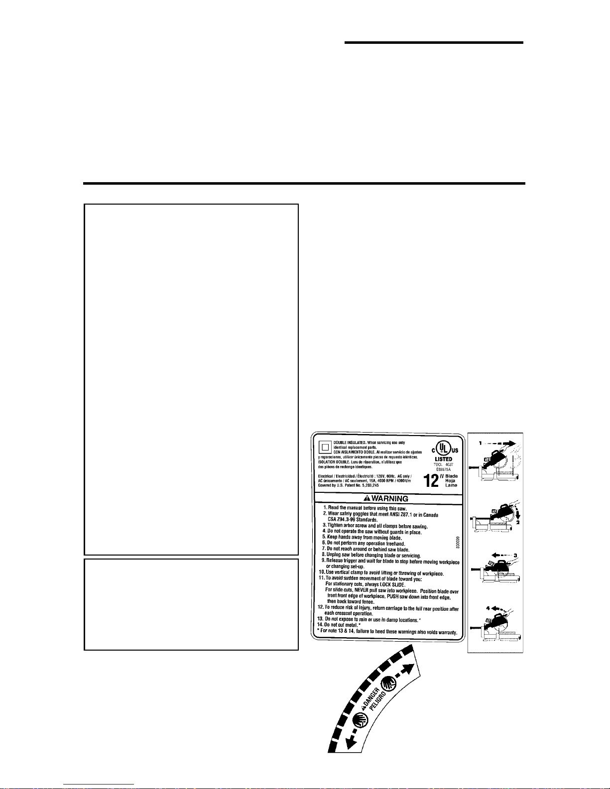
Find and read the following labels on
the miter saw.
WARNING: To reduce the risk of
mistakes that could cause serious, permanen t inju r y, do not
plug the miter saw in until the following steps have been satisfactorily completed.
• Co mpl etely assem ble and align
saw. (See “Assembly” and “Alignment” sections within.)
• L earn the use and function of the
ON-OFF switch, upper and lower
blade guards, miter lock lever , bevel
3

Safety Instructions for Miter Saws (continued)
When Installing Or Moving The Miter Saw
Before moving the saw , l ock th e
miter, bevel, slide and power head
posi t ion s . Un pl ug t h e pow er c or d.
To reduce the risk of back injury, get
help when you need to lift the saw.
Never carry the tool by the cord or
power head trigger handle. Damage
to insulation could cause an electric
shock. Damage to wire connections
could cause a fire.
Reduce the Risk of Dangerous
Environment. Use the miter saw in a
dry, location, protected from rain.
Keep work area well lighted.
Place the saw so neither the user nor
bystanders are forced to stand in line
with the blade. Thrown debris could
injure people in its path.
To reduce the risk of injury from
unexpected saw movement:
• Pla ce the miter saw on a firm level
surface where there is plenty of
room for handling and properly sup-
porting the workpiece.
• Support the miter saw so the tabl e is
level and the saw does not rock.
• Bolt, screw or clamp the saw to its
support.
• Never Stand On To ol. Serious
injury could occur if the tool tips or
you accidentally hit the cutting tool.
Do not store anything above or near
the tool where anyone might stand
on the tool to reach them.
To reduce the risk of injury or
death from electrical shock:
• Make sure your fingers do not touch
the plug’s metal prongs when plugging or unplugging the miter saw.
• This TOOL IS DOUBLE INSULATED to give you added protection. Double insulation does not take
the place of normal safety precautions when operating this tool. When
servicing this double insulated tool,
use only identical parts.
Before Each Use
Inspect your miter saw.
Disconnect The Miter Saw. To
reduce the risk of injury from accidental starting, unplug the saw , before
changing the setup, changing the
blade or adjusting anything.
Compare the direction of rotation
arrow on the guard to the direction
arrow on the blade. The blade teeth
should always point downward at the
front of the saw.
Tighten the arbor screw.
Tighten the cover plate stop screw.
Check For Damaged Parts. Check
for:
• Proper A lignment of moving parts,
• Damaged electric cords,
• Binding of moving parts,
• Broken parts,
• Stable mounting,
• Function of arm return spring and
lower guard: Push the arm all the
way down, then let it rise up until it
stops by itself. Check the lower
guard to see if it closed fully. If it did
not, follow the instructions in the
“Troubleshooting ” section.
• Smooth, solid movement of sliding
assembly.
• Other conditions that may affect the
way the miter saw works.
4

If any part of this m iter saw is missing,
bent, or broken in any way, or any
electrical parts don't work, turn the
saw off and unplug it. Replace damaged, missing, or failed parts before
using the saw again.
Keep Guards In Place, in working
order, and in proper adjustment.
Maintain Tools With Care. Keep the
miter saw clean for best and safest
performance. Follow instructions for
lubricating. DON’T put lubricants on
the blade while it’s spinning.
Remove Adjusting Keys And
Wrenches from tool before turning it
on.
To Reduce the Risk of Injury From Jams, Slips Or Thrown Pieces
• Use Only Recommended Accessories. (See “Accessory” section
within.) Consult this owner’s manual
for recommended accessories. Follow the instructions that come with
the accessories. The use of
improper accessories may cause
risk of injury to persons.
• Choose the right 12-inch diameter
blade for the saw and the material
you plan to cut.
• Mak e sure the blade is sharp,
undamaged and properl y aligned.
With the saw unplugged, push the
power head all the way down. Hand
spin the blade and check for clearance. Tilt the power head to 45
degrees left and right bevel and
repeat the check. If the blade hits
anything, make the adjustments
shown in “Alignment (Adjustments)”
section.
• Make sure the blade and arbor collars are clean.
• Make sure the collars' recessed
sides are facing the blade.
• Using the 1/4” hex end of combination wrench (supplied) or a 1/2-inch
box end wrench, make sure the left
hand thread arbor screw is firmly
tightened counterclockwise.
• Make sure all clamps and locks are
tight and there is no excessive play
in any parts.
• Keep Work Area Clean. Cluttered
areas and benches invite accidents.
Floor must not be slippery .
To reduce the risk of burns or other
fire damage, never use the saw near
flammable liquids, vapors or gases.
Plan Ahead To Protect Your Eyes, Hands, Face and Ears
Know Your Miter Saw. Read and
understand the owner ’s manual and
labels affixed to the tool. Learn its
applications and limitations as well as
the specific potential hazards peculiar
to this tool.
To reduce the risk of injury from accidental contact with moving parts,
don’t do layout, assembly, or setup
work on the miter saw while any parts
are moving.
To Reduce the Risk of Accidental
Starting. Make sure switch is “OFF”
before plugging miter saw into a
power outlet.
Plan your work.
Use The Right Tool. Don’t force tool
or attachment to do a job it was not
designed to do. Use a different tool
for any workpiece that can’t be held in
a solidly braced, fixed position.
5
Safety Instructions for Miter Saws (continued)
CAUTION: Because of the slid ing
action of this saw, this machine
is not designed for cutting metals. Use this miter saw to cut
only wood and wood like products. Other materials may shatter , bind on the blade, start fires
or create other dangers.
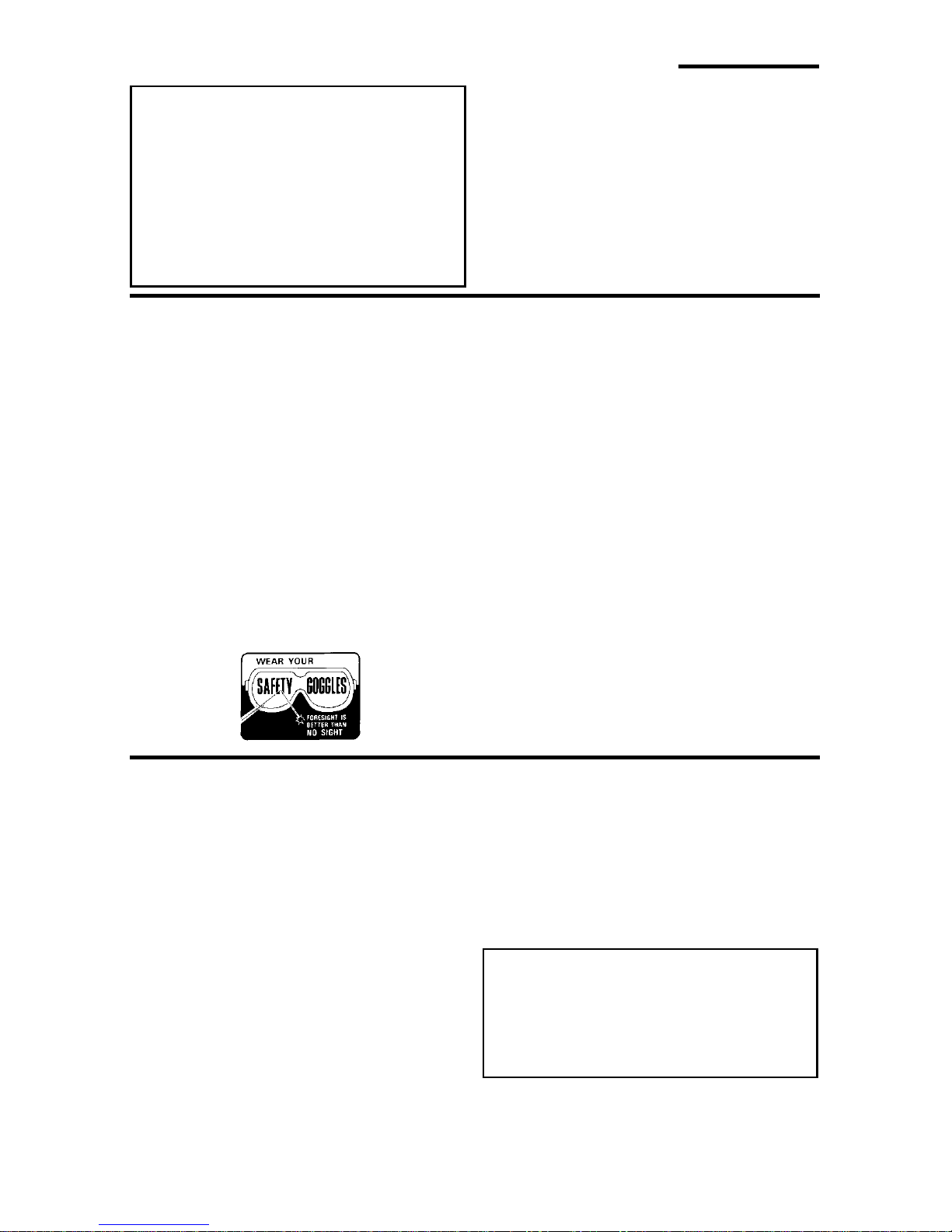
Dress F o r Safety
Any power tool can throw foreign
objects into the eyes. This can result
in permanent eye damage. Wear
safety goggles (not glasses) that
comply with ANSI Z87.1 (or in Canada CSA Z94.3-99) shown on package. Everyday eyeglas ses have only
impact resistant lenses. They are not
safety glasses. Safety goggles are
available at many local retail stores.
Glasses or goggles not in compliance
with ANSI or CSA could seriously hurt
you when they break.
Preparing to Make Cut
Do not wear loose clothing, gloves,
neckties or jewelry (rings, wrist
watches) They can get caught and
draw you into moving parts.
• Wear nonslip footwear.
• Tie back lon g ha ir.
• Roll long sleeves above the elbow.
• Noise levels vary widely. To reduce
the risk of possible hearing damage,
wear ear plugs or muffs when using
miter saw for hours at a time.
• For dusty operations, wear a dust
mask along with safety goggles.
Inspect Your Workpiece. Make sur e
there are no nails or foreign objects in
the part of the workpiece to be cut.
Plan your work to reduce the risk
of thrown pieces caused when the
workpiece binds on the blade and
is torn from your hands.
Plan how you will make the cut.
Always:
• Make sure the blade is not spinning.
• Raise the blade.
• Slide the saw out above the front
edge of the workpiece before starting saw, and
• Push the sawblade down on top of
the wood and back toward the rear
of the saw to make the cut.
DANGER: NEVER pull the saw
toward you during a cut. The
blade can sudden ly climb up on
top of the workpiece and force
itself toward you.
6

Plan The Way You Will Hold The Workpiece From Start To Finish.
• Avoid awkward operations and hand
positions where a sudden slip could
cause fingers or hand to move into
the blade.
• Don’t Overreach. Keep good footing and balance.
• Keep your face and body to one
side of sawblade, out of line with a
possible thrown piece.
• Cu t only one workpiece at a time.
• Never cut Freehand :
- Brace your workpiece solidly
against the fence and table top so
it will not rock or twist during the
cut.
-Make sure there’s no debris
between the workpiece and its
supports.
- Make sure no gaps between the
workpiece, fence and table will let
the workpiece shift after it is cut in
two.
• Keep the cut off piece free to move
sideways after it's cut off. Otherwise,
it could get wedged against the
blade and thrown violently.
• Clear everything except the workpiece and related support devices
off the table before turning the miter
saw on.
• Secu re Work . Use cl amps or a
vise to help hold the wor k wh en it’s
practical.
Use extra caution with large, very
small or awkward work pieces:
• Use extra supports (tables, saw
horses, blocks, etc.) for any workpieces large enough to tip when not
held down to the table top.
• Never use another person as a substitute for a table extension, or as
additional support for a workpiece
that is longer or wider than the basic
miter saw table or to help feed, support or pull the workpiece.
• Do n o t u s e th is saw to cut pieces
too small to let you easily hold the
work while you keep the thumb side
of your index (pointer) finger against
the outside edge of the fence.
• When cutting irregularly shaped
workpieces, plan your work so it will
not slip and pinch the blade and be
torn from your hands. A piece of
molding, for example, must lie flat
against the table or fence, or be held
by a fixture or jig that will not let it
twist, rock or slip while being cut.
• Properly support round material
such as dowel rods, or tubing. They
have a tendency to roll while being
cut, causing the blade to "bite." To
avoid this, always use a fixture
designed to properly hold your
workpiece.
Whenever Saw Is Running
WARNING: Don't al low familiarity
(gain ed f rom f requent use of
your miter saw) cause a careless
mistake. A careless fraction of a
second is enough to cause a
severe injury.
Before starting your cut, observe the
miter saw while it runs. If it makes an
unfamiliar noise or vibrates excessively , stop immediately. Turn the saw
off. Unplug the saw. Do not restart
until finding and correcting the problem.
Keep Children Away. Keep all visitors a safe distance from the miter
saw. Make sure bystanders are clear
of the miter saw and workpiece.
7

Safety Instructions for Miter Saws (continued)
Never confine the piece being cut
off. Never hold it, clamp it, touch it, or
use length stops against it while the
blade is spinning. It must be free to
move sideways on its own. If confined, it could get wedged against the
blade and be thrown violently.
Let the blade reach full speed
before cutting. T his will help avoid
thrown workpieces.
Don’t Force Tool. It will do the job
better and safer at its designed rate.
Feed the saw into the workpiece only
fast enough to let the blade cut without bogging down or binding.
Before Leaving The Saw
Never Leave Tool Running Unattended. Turn power off. Wait for all
moving parts to stop.
Make Workshop Child Proof. Install
a padlock through the hole provided
Before freeing jammed material:
• Turn miter saw “OFF” by releasing
trigger switch.
• Wait for all moving parts to stop.
• Unplug the miter saw.
After finishing a cut:
• Keep holding the power head down.
• Release the switch, and wait for all
moving parts to stop before moving
your hands or raising power head.
• If blade doesn’t stop within 6 seconds, unplug the saw and follow the
instructions in the Trouble Shooting
section for fixing the blade brake
before using the saw again.
in the trigger to prevent unauthorized
usage. Lock the shop. Disconnect
master switches. Store tool away
from children and others not qualified
to use the tool.
Glossary of Terms for Woodworking
Arbor
The shaft on which a cutt ing tool is
mounted.
Bevel Cut
An angle cutting operation made through
the face of the workpiece.
Compound Cut
A simultane ous bevel and miter cutting
operation.
Crosscut
A cutting operation m ade across the width
of the workpiece.
Dado
A non-through cut which produces a
square sided notch or
piece
Freehand
Doing a cut without holding the workpiece
against both the table and fence. Most
workpieces can be held down with your
trough in the work-
hand. Large or wide pieces should be
clamped to th e fence or table.
Gum
A sticky, sap based residue from wood
products.
Heel
Misalignment of the blade.
Kerf
The amount of material removed by the
blade in a throug h cut or the slot produc ed
by the blade in a nonthr ough or part ial cut.
Miter Cut
An angle cutting operation made across
the width of t he workpiece.
Offal
Unsecured pei ce of material aft er making
cut.
Resin
A sticky, sap based substan ce that has
hardened.
8
Revolutions Per Minute (RPM)
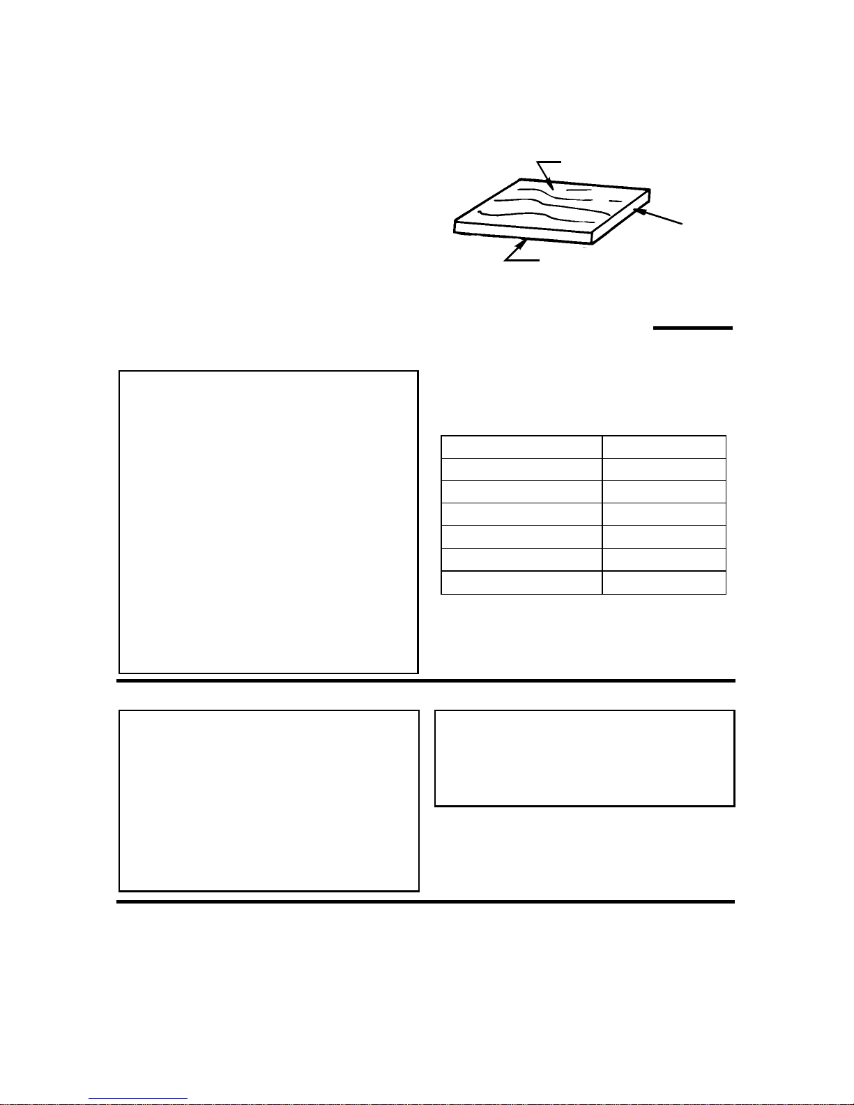
Workpiece
The number of turns comp let ed by a spinning object in one minute.
Sawblade Path
The area of the workpiec e or table top
directly in li ne with either the travel of the
blade or the part of the workpiece which
will be, or has been, cut by the blade.
Set
The distanc e that the tip of the sawblade
tooth is bent (or set) outward from the
face of the blade.
The it em on which t he cutting operation is
being performed. The surfaces of a workpiece are commonly referred to as fa ces,
ends, and edges.
Face
Edge
Motor Specifications and Electrical Requirements
Power Supply and Motor Specifications
WARNING: To reduce the risk of
electrical hazards, fire hazards
or damage to the tool, use
proper circuit protection. Your
tool is wired at the factory for
operation using the voltage
shown. Connect tool to a power
line with the appropri ate voltage
and a 15-amp branch circuit.
Use a 15-amp time delay type
fuse or circuit breaker. To
reduce the risk of shock or fire,
if pow er cord is wor n or cut, or
damaged in any way, have it
replaced immediately .
The A-C motor used on this tool is a nonreversi ble universal typ e, having the following spe cifications:
Voltage 120
Amperes 15
Hertz (Cycles) 60
Phase Single
RPM 4000
Shaft Rotation Clockwise
Brake Automatic
End
General Electrical Connections
DANGER: To reduce the risk of
electrocution:
1. Use only identical replacement
parts when servicing. Servicing should be performed by a
qualified service technician.
2.Do not use in rain or where
floor is wet.
110-120 Volt, 60 Hz. T ool Information
Double Insulated
The miter saw is double i nsulated to provide a double layer of insulation between
you and the tool’s electrical system. All
exposed metal part s are isolated from the
WARNING Do not permit fingers
to touch the terminals of plug
when installing or removing the
plug to or from the outlet.
If power cord is cut, or damaged in any
way, have it replaced immediately.
internal metal motor components with
protect ing insulation.
9
Motor Spec ifica tio ns and Electr ical Re qu iremen ts ( contin ued )
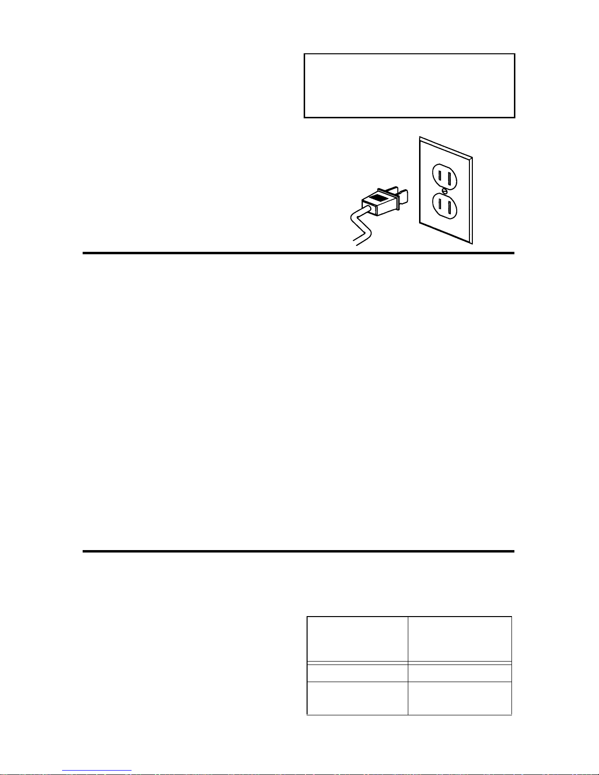
Polarized Plug
Y our uni t has a plug that looks like the one
shown on next page.
To reduce the risk of electrical shock, this
appliance h as a polar ized pl ug (one bla de
is wider than the other ). Thi s plug will fit in
a polarized out let onl y one way, if the plug
does not fit fully i n the outl et, reve rse plug.
If it still does not fi t, contact a qualified
electrici an to install the proper outlet. Do
not change the plug in any way.
Motor Safety Protection
1. Connect this too l t o a 120v, 15-amp
branch circui t with a 15-amp time delay
fuse or circui t breaker. Using the wrong
size fuse can damage the motor.
2. If the motor won't st art, release the trigger switch immediately. Unplug The
Tool. Check the saw blade to make
sure it turns freely . If the blade is free,
try to start the motor again. If the mo tor
still does not start, refer to the "Motor
Troubleshooting Char t."
3. If the motor sudden ly stalls while cutting wood, release the trigger switch,
unplug th e tool, and fre e the bla de from
the wood. The motor may now be
restarted and the cut finished.
4. Fuses may "blow" or circuit breakers
may trip frequently if:
WARNING: Double insulation
does not take the place of normal
safety precautions when operating this to o l .
a.Motor Is Overloaded-Overloading
can occur if you cut too rapidly or
make too many start/stops in a short
time.
b. Line voltages are more than 10%
above or below the nameplate voltage. For heavy loads, however, the
voltage at m ot o r t erm i na ls m ust equal
the voltage specified on nameplate.
c. Improper or dull saw blades are used.
5. Most motor troubles may be traced to
loose or incorrect connections, overload, low voltage (such as small size
wire in the supply cir cuit) or to overly
long supply circuit wire. Always check
the connections, the load and the supply ci rcuit whe never motor do esn't wor k
well. Check wire sizes and length with
the Wire Size Chart below.
Wire Sizes
NOTE: Make sure the proper extension
cord is used and is i n good condition. The
use of any extension cord will cause
some loss of power. To keep this to a minimum and to prevent ove rheating and
motor burn-ou t, use the t able below to
determine the m inimum wire size (A.W .G.)
extension cord.
For circuits that are farther tha n 100 feet
away from electrical service box, the wire
size must be i ncreased proportionately in
order to deliver ample voltag e to the saw
motor.
Extension Cord
Length
110-120V
0-2 5 F t.
26-50 Ft.
10
Wire Sizes
Required for 120V
(A.W.G.)
14
12
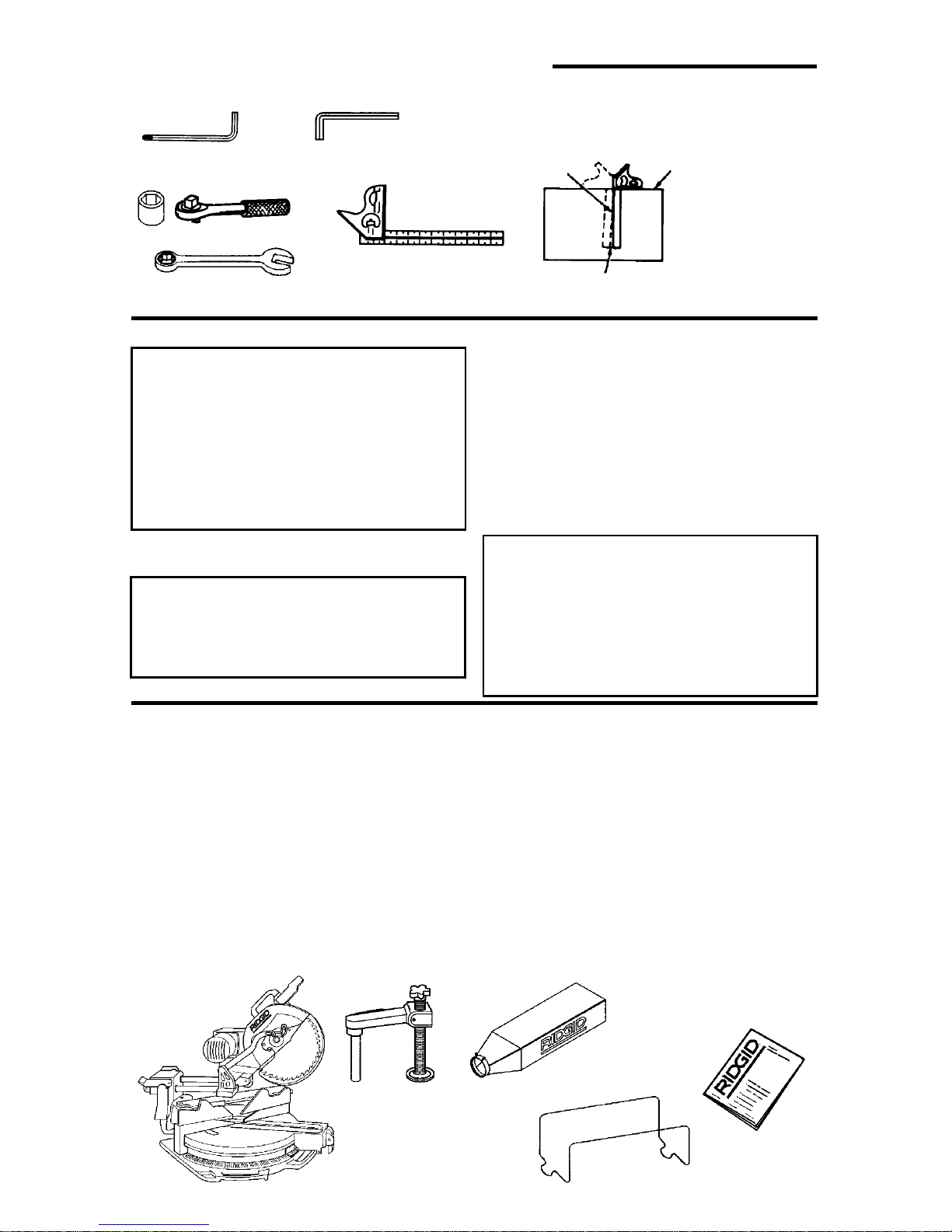
Unpacking and Checking Contents
Tools Needed
Combination Square Must be True
Hex “L” Wrench
1/4" (supplied)
19 mm Socket
Combination
Unpacking
Draw Light
Hex “L” Wrench
4mm, 5mm, 6mm
Combination Square
12mmWrench (2)
Line on Board
Along thi s Edge
Should be no Gap or Overlap when Square
is Flipped Over in Dotted Position
Straight Edge of
Board 3/4" Thick
This Edge Must
be Perfectly
Straight
WARNING: To reduce the risk of
injury from unexpected starting
or electrical shock, do not plug
the power cord into a power
source outlet during unpacking
and assembly. This cord must
remai n un pl ug ged when eve r yo u
are working on the saw.
This Miter Saw is shipped complete in
one box.
WARNING: Although compact,
this saw is he avy. To reduce th e
risk of back injury, get help whenever you have t o lift the saw.
List of Lo ose P arts
NOTE: Before beginni ng assembly, check
that all parts are included. If you are missing any part , do not assem ble the saw. Email us at info@ridgidwoodworking.com if
any parts are damaged or missing.
Sometimes small parts can get lost in
packaging material. Do not throw away
any packaging until saw is put together.
Check packaging for missing parts before
contacting RIDGID. A complete parts list
1. Before removing the mit er saw from t he
carton tighten the slide lock knob to
guard against sudden movement.
2. Remove the miter saw from the carton by
lifting the saw with the carrying handle.
3. Place the saw on a secure, stationary
work surface and look the saw over
carefully.
WARNING: If any part is missing
or damaged, do not plug the saw
in until the m issing or dama ge d
part is correctly replaced. To
avoid electric shock, use only
identical replacement parts when
servicing double insulated tools.
(Repai r Part s) is at the end of the manual.
Use the list to identify the number of the
mis sing par t .
The following parts are incl uded:
Part or Assembly Qty.
A Basic Saw Assembly .......................... 1
B Workp ie ce Cl a mp ... ................. ........... 1
C Dust Bag............................................. 1
D Dust Bag Frame.................................. 1
E Owne rs M a nua l................................... 1
A
B
C
E
D
11
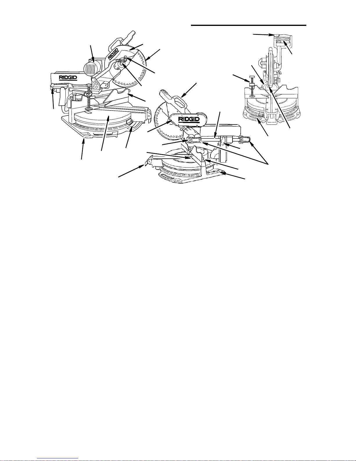
Getting to Know Your Miter Saw
1
10
7
8
16
1.Warn ing Label
2.Upper Blade Guard - Supports the
motor , handle, switch, blade an d lower
guard.
3. Lower Blade Guard - The bl ade gua rd
helps protect your hands from the
blade in the raised position. To reduce
the risk of binding on the workpiece, it
retracts as the blade is lowered.
4.Cover Plate - Holds the lower guar d
and is attached to upper guard. Prevents the arbor screw from backing
out when properly attached with the
cover plate stop screw.
5.Cover Plate Stop Screw - When this
screw is loosened, the cover plate is
rotated to the rear, allowing for blade
removal/replacement.
6.Sliding Fence(s) - Fen ce(s) slide lef t/
right to provi de ma ximum support for
the workpiece.
7. Table - Sits in base, supports pivot
and allows for approx imately 62° mit er
left and right.
8.Base - Supports table, holds accessories and allows for work bench or leg
set mounting.
9. Miter Indicator - Indicates the angle
(miter) the bl ade is set at.
10.Bevel Lock Lever - Locks the miter
20
2
3
25
5
11
24
21
4
6
12
19
18
9
17
13
23
22
26
14
15
saw at a desired bevel angle.
11.Top Carrying Handle - Convenient
way to transport saw.
12. Slide T u be(s) - Allow the blade to slide
for cutting various workpiece widths.
13.Slide Lock Knob - Prevent s th e saw’s
sliding motion by locking the carriage
in place.
14.Slide Fence Lock Knob - Locks
fence at cor rect cutting position.
15.Combination Wrench - 1/4" Hex “L”
wrench.
16.Miter Lock Lever/Miter Index
Thumbwheel - The miter lock lever
securely locks the saw at a desired
miter angle. Index points have been
provided at 0°, 15°, 22.5°, 31.6° (Crown
molding), 45°, 60° Left and Right.
17.The Repeat-A-Cut ™ - Surfac e allows
pencil marks to be made and easily
erased for duplicate cuts.
18.Depth Adjustment Clamp and Head
Hold Down - Limits the saw’s down-
ward trave l f or use when cutting
dadoes and locks the saw in the lowered position for compact storage.
19.Arbor Lock Pin - Allows the user to
keep blade f rom rotating while ti ghtening or loosening arbor during blade
replacement or removal.
12
20. S w i tc h In te rlock Bu tton - Prevents
trigger switch from being accidentally
engaged.
21.On/Off Trigger Switch - To prevent
the trigger from being accidentally
engaged, a lock- off but ton i s prov ided.
To start the tool, pres s in the switch
interlock button and squeeze the tri gger. Release the trigger t o stop the
miter saw. Inst all a padlock through
the hole in the tr igger to prevent unauthorized use.
22.Bevel Index Pin - This pin provides
indexes at 0° and 22.5 °, CM, and 45°
left and right.
Assembly
WARNING: For your own safety,
never connect plug to power
source outlet until all assembly
steps are complete, and you
have read and understood the
safety and operational instructions.
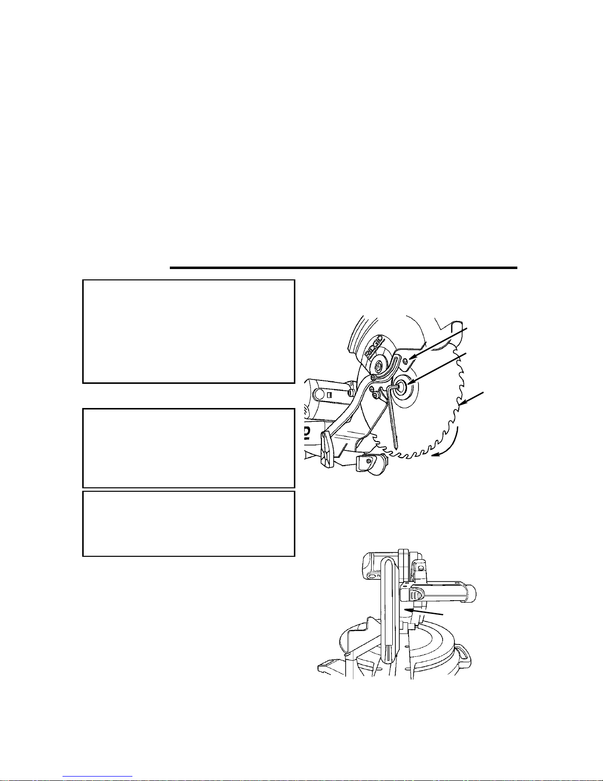
Installing or Removing the Blade
23.Front Carry Handles - Convenient
way to transport the saw.
24.Workpiece Clamp - Helps to h old
workpiece in position for precise cutting. Quick release allows easy movement for workpiece width adjustment.
Pin of clamp fit s in either hole in rear
at fence.
25.Bevel Indicator - Indicates the angle
(bevel) the blade is set.
26.Cord Wrap Brackets
Coverplate
Stop
Screw
Arbor
Screw
Blade
WARNING: To reduce the risk of
injury from a thrown workpiece
or thrown pieces of blade, do not
use a blade larger or smaller than
12" diameter.
WARNING: To reduce the risk of
injury fro m unexpected starting,
unplug the saw whenever you are
removing or installing the blade.
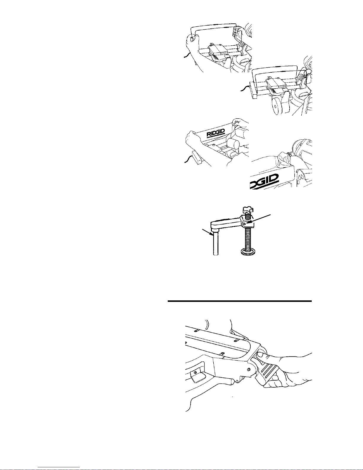
1.Unplug the saw from the outlet. Cutting head is up.
2.Rotate t he lower blade g uar d by hand.
Loosen, but do not remove, the cover
plate stop sc rew u sing t he Phil lip s en d
of combination wrench.
3.Lift the lower guard up and tilt the
lower guard asse mb ly back so the
arbor screw is exposed.
4.Fit 1/4” hex end of combination tool in
arbor screw or use 1/2” box end
wrench.
n
e
s
o
o
L
5.Press the arbor lock and hold it in
firmly while turning the wrench clockwise. The arbor lock will engage after
some turning of the wrench.
Arbor Lock
NOTE: The arbor screw has a left hand
thread. This hel ps prevent unwanted
looseni ng of the arbor screw during normal operat ion.
13
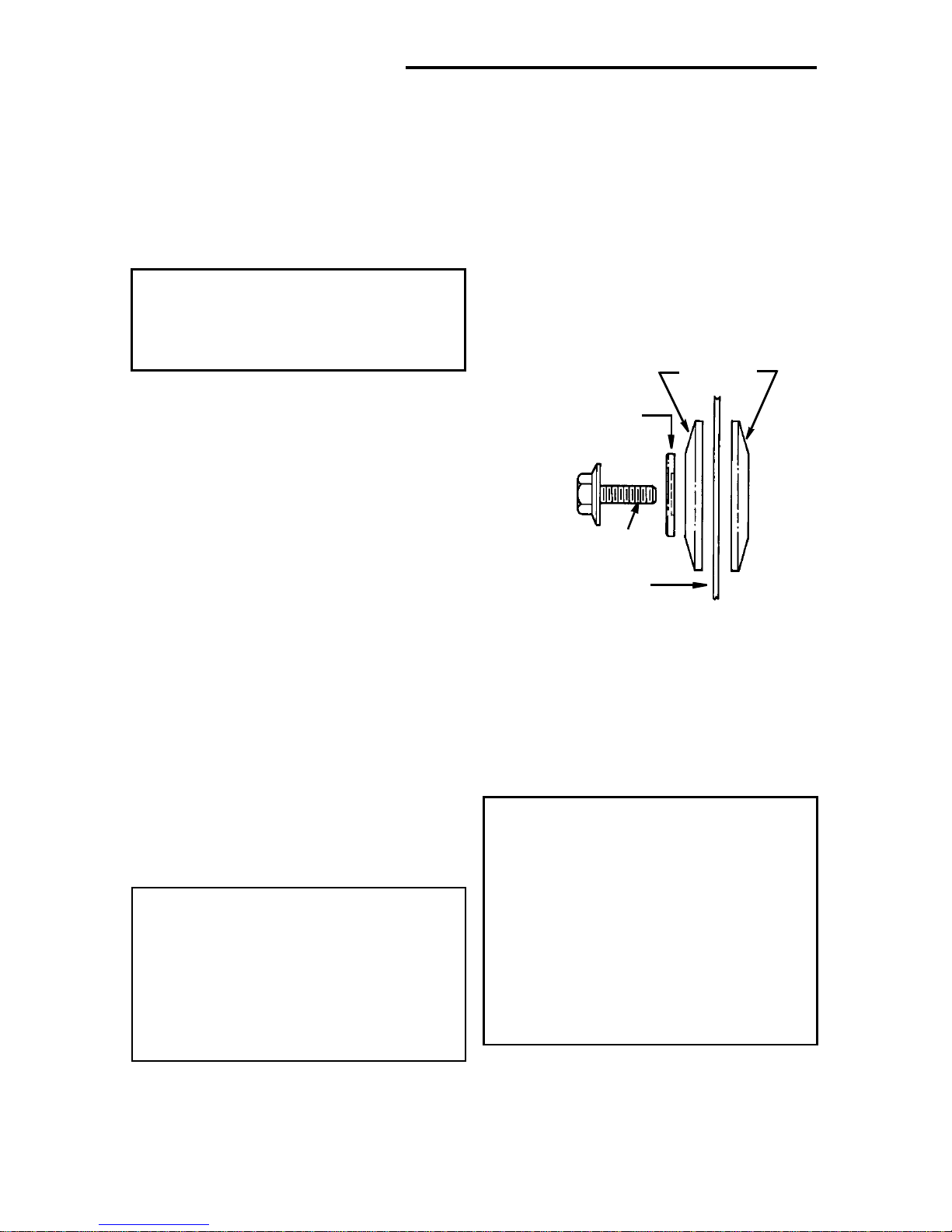
Assembly (continued)
6. Remove the arbor screw, arbor
washer, outer blade collar, and the
blade.
NOTE: Pay attention to pieces removed,
noting their pos ition and direction they
face (see illustration). Wipe the blade collars clean of any sawd ust bef ore inst all ing
the new blades.
CAUTION: To reduce the risk of
cuts from extremely sharp teeth:
Wear gloves when installing or
removing sawblade.
See cautions in “Using Carbide Tipped
Blades” section concerning inspection,
use, and selection of carbide tipped and
other sawblades.
7.Install the new 12" blade (see recommended accesso ry l ist). Make sure
the rotation arrow on the blade
matches the clockwise rotation arrow
on the upper guard. The blade teeth
should always point downward at the
front of the saw.
8.Instal l the outer blade collar, blade
washer and arbor screw. Press the
arbor lock and turn the combination
wrench or the 1/2" wrench counter
clockwise to sec ure the bl ade. Tighten
arbor screw usin g modera te force, but
do not overtighten.
9.Lower the lower blade guard until the
slot in cover plate rests all the way
down on the cover plate stop screw.
Tight en the scr ew with the Phi llip s en d
of the combination wrench.
DANGER: Never use saw without
guard cover plate securely in
place. It keeps the arbor screw
from falling out if it accidentally
loosens, and prevents the spinning blade from coming off the
machine.
10.Be sure the arbor lo ck is released so
the blade turns freely.
Blade
Collars
Blade
Washer
(Hollowed Side
Toward Blade)
Arbor screw
(Left Hand Thread)
Sawblade
NOTE: The arbor lock can be damaged
by improper use. If the arbor lock will not
hold, lower the blade down on to a scrap
piece of wood pos it ioned against the
fence. Th is wi ll serve as an alter nate locking means.
WARNI NG: Make sure the collars
are clean and properly arran ged .
After installing a new blade,
make sure the blade clears the
table slot at the 0° and 45° bevel
positions. Lower the blade into
the table slot and check for any
contact with the base or turn
table structure. If blade contacts
table, seek authorized service.
If blade contacts insert, refer to “Alignment“section for adjustme nt.
14
Assembling Dust Bag
1. Locate the dust bag fram e and cloth
dust bag.
2. Clip the dust bag frame in place on the
slide tubes as shown.
3. Slide the cloth dust bag over the dust
bag frame.
4. Connect the dust elbow t o the dus t port
on the upper blade guard.
5. Clamp dust bag onto elbo w.
NOTE: If connecting a 2-1/2" wet/dry vac
hose to the saw, do not attach the dust
bag frame, dust bag and elbow to the
saw. Connect the wet/dry vac hose
directly to the dust port on the upper blade
guard.
Workpiece Clamp Installation
The workpiec e clamp is used to help hold
the workpiece in the correct cutting position. It may be used on either the left side
of the miter saw or the right side. Before
turning the saw on make sure the workpiece clamp does not int erfere with the
cutting action of the saw.
1. Align pin in clamp shaft with keyway in
fence. In sert clamp shaft and rot ate.
Four Basic Saw Controls
In order to properly adjust and align the
Sliding Compound Miter Saw there are
four basic controls that must be understood.
1. Miter lock lever and miter index wheel
To change the miter setting of the
blade:
a. Raise the miter lock lever .
b. Rotate the miter index wheel partial ly
downward to disengage the current
index and engage the next index.
c. Rotate the miter index wheel com-
pletely downward to bypass all mit er
indexes.
d. Turn the tabl e to the desired miter
setting and lock the miter lock lever.
Clamp
Support
Shaft
Quick Rele a se
Button
15
Four Basic Saw Controls (continued)
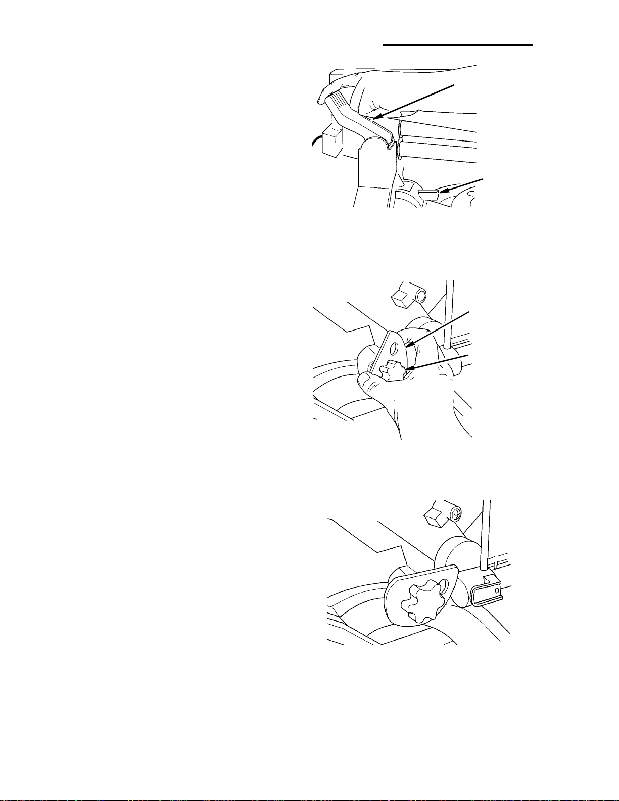
2. B e vel lo c k le v e r/i n de x pin
To change the bevel setting of the
blade:
a. Pull the bevel lock lever for w ard.
Then rotate the bevel index pin
downward. This will allow the blade
to be tilted and at the same time “bypass” the preset bevel indexes.
b. To engage the pr eset bevel indexe s,
rotate the bevel lock index pin up.
c. Engage bevel index pin and/or bevel
lock lever before cutting.
3. Depth Adjustment Cam and Head Hold
Down
To release the blade -
a. While applying light downward pres-
sure on the handle, pull the depth
adjustment cam to th e right, then
raise the blade.
NOTE: It is not necessary to loosen
depth adjustment knob.
b. Rotate the depth adjustment cam so
the flat on the cam is facing upward.
NOTE: Head Hold Down is for transport and storage purposes only. No
cutting operations should take place
while hold down is engaged.
To lock the blade in the lower posit ion.
a. Pull the depth adjustment cam to the
right and lower the blade into the
table.
b. Rotate the depth adjustment cam
until slot engages pin on upper
guard.
4. Slide lock knob
Turn the slide lock knob counterclockwise to loosen and clock wis e to tight en.
Loosening t he knob will allow the powerhead to sl ide back and forth. Tightening the knob will lock the powerhead in
place.
Bevel Loc k
Lever
Bevel Index
Pin
Depth
Adjustment
Cam
Depth
Adjustment
Knob
16
Alignment (A dju stm ents)
WARNING: To reduce the risk of
injury from unexpected starting
or electrical shock, do not plug
the saw in. The power cord must
remai n un pl ug ged when ev er y ou
are working on the saw.
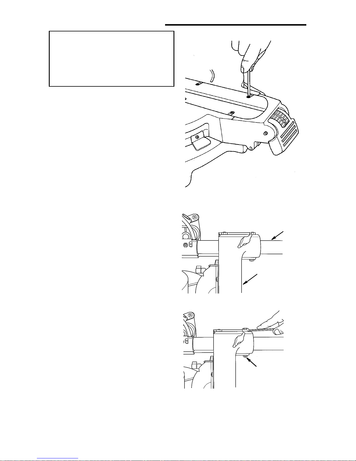
Step One: Repositioning Zero Clearance Blade Insert
The zero cleara nce blade insert needs to
be repositioned so it is temporarily out of
the way when aligning the blade. It may
be replaced after the blade is aligned.
1. Loosen the three screws that secure
the zero cle arance blade insert on one
side of the blade.
2. Slide the zero clearance insert away
from the blade as far as possi b l e .
3. Retighten the three screws.
4. Repeat steps 1-3 for the opposite side
of the blade.
Step Two: Slide T ube Adju stment
1. Plac e the powerhead in the 0° miter/ 0°
bevel index and lock head in lower position.
2. Check to see that the blade is approxi-
mately centered between the two zero
clearance blade inserts. Also check for
play between the rig ht slide rai l and the
pivot assembly.
3. If adjustment is required loos en the jam
nuts on all four gib screws as shown.
4. Loosen the top two gib screws.
5. Tighten or loosen the lower two gib
screws as required to center the blade
between the zero clearance inser ts.
6. Tighten the lower two jam nut s.
7. To minimize play in the slide tubes
gradually tighten the top t wo gib
screws while at t he sam e ti m e sli ding
the powerhead back and forth. Tighten
the top jam nuts.
Slide Rail
Pivot
Assembly
Gib Screw
17
 Loading...