

RIDGID MS1250 Owner's Manual

MS1250
OWNERS MANUAL
For Your Safety:
Read all instructions carefully
Save this manual for future
referenece
12 INCH COMPOUND
MITER SAW
WITH LEGSET
Part No. SP6449 Printed in Taiwan

Table of Contents
Section Page
Table of Contents .......................................... 2
Safety Instructions For Miter Saw ................. 2
Safety Signal Words ................................... 2
Before Using The Saw ............................... 3
When Installing Or Moving The Miter Saw .3
Before Each Use ........................................ 4
To Reduce the Risk of Injury From Jams,
Slips Or Thrown Pieces ............................ 4
Plan Ahead To Protect Your Eyes, Hands,
Face and Ears .......................................... 5
Dress For Safety ........................................ 5
Preparing to Make Cut ............................... 6
Whenever Saw Is Running ......................... 7
Before Leaving The Saw ............................7
Glossary of Terms for Woodworking ............. 8
Motor Specifications and Electrical
Requirements ........................................... 8
Power Supply and Motor Specifications ..... 8
General Electrical Connections .................. 9
110-120 Volt, 60 Hz. Tool Information .........9
Motor Safety Protection .............................. 9
Wire Sizes ................................................ 10
Unpacking and Checking Contents ............. 10
Tools Needed ........................................... 10
Unpacking ................................................ 10
List of Loose Parts ................................... 10
Assembly .....................................................1 2
Assembling and Aligning the
Table Extension ...................................... 12
Attaching Dust Elbow and Dust Bag .........12
Installing or Removing the Blade ............. 13
Getting to Know Your Miter Saw ................. 14
Alignment (Adjustments) ...............................16
Step One: Blade Square to Table
(Bevel Alignment) .....................................16
Assembling Leg Set .................................... 18
Attaching Feet ..........................................18
Mounting The Miter Saw ............................. 19
Mounting Saw on Supplied Legset ........... 19
Mounting Saw on Other Legsets or Work
Benches .................................................1 9
Portable Applications ............................... 19
Section Page
Safety Instructions for Basic Saw
Operations .............................................. 20
Before Each Use ........................................ 20
To Reduce the Risk of Injury From Jams,
Slips Or Thrown Pieces ..........................20
PlanAhead To Protect Your Eyes, Hands,
Face and Ears ........................................21
Dress For Safety ...................................... 21
Preparing to Make the Cut ....................... 21
Whenever Saw Is Running .......................23
Before Leaving The Saw: .........................23
Basic Saw Operations .................................24
Body and Hand Position ...........................24
Miter Scale Usage ....................................24
Sliding Fence ...........................................25
Miter Cut ...................................................25
Bevel Cut ..................................................25
Compound Cut .........................................26
Cutting Compound Miters on
Picture Frames and Boxes .....................26
Cutting Bowed Material ............................ 26
Workpiece Support ..................................27
Auxiliary Fence .........................................27
Cutting Base Moldings .............................27
Cutting Crown Moldings ...........................28
Two Methods of Cutting Crown Molding ..28
Maintenance and Lubrication ......................30
Maintenance .............................................30
Lubrication ................................................ 30
Accessories .................................................31
Prohibited Accessories ..............................31
Basic Blade Requirements ....................... 31
Using Carbide Tipped Blades ......................31
Troubleshooting Guide ................................32
General ....................................................32
Motor ........................................................ 33
Wiring Diagram ............................................33
Trouble Shooting of Brake by Qualified
Service Person Only ...............................33
Repair Parts ................................................34
Notes ...........................................................42
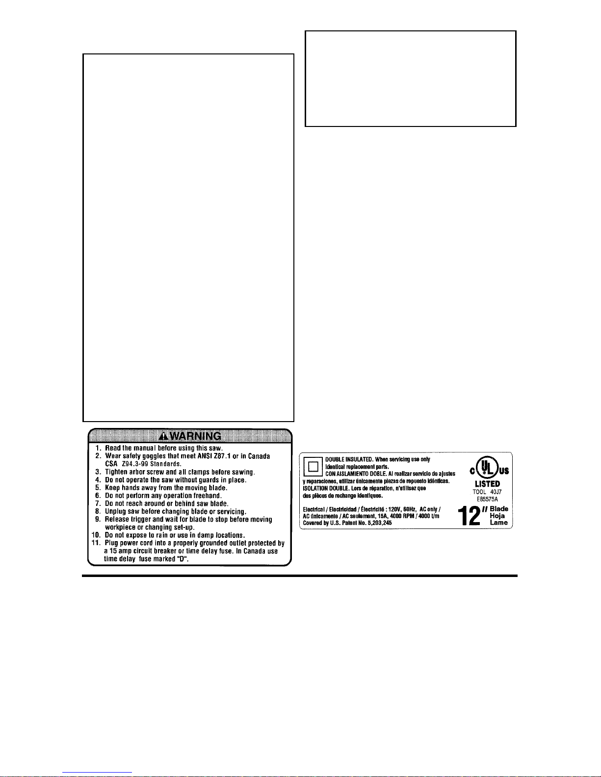
Safety Instructions For Miter Saw
Safety is a combination of common sense, staying alert and knowing how
your miter saw works. Read this manual to understand this miter s aw.
Safety Signal Words
DANGER: means if the safety infor-
mation is not followed someone wi ll
be seriously injured or killed.
WARNING: means if the safety infor-
mation is not followed someone
could be seriously injured or killed.
CAUTION: means if the safety infor-
mation is not followed someone may
be injured.
2
Before Us ing The Saw
WARNING: Some dust created by
power sanding, sawing, grinding,
drilling, and other construction
activities contains chemicals
known (to the S tate of Cal i fornia)
to cause cancer, birth defects or
other reproductive harm. Some
examples of these chemicals are:
• Lead from lead-bases paints,
• Crystalline silica from bricks
and cement and other masonry
products, and
• A rsenic and chromium from
chemically-treated lumber.
Your risk from these exposures
varies, depending on how often
youdothistypeofwork.To
reduce your exposure to these
chemicals: work in a well ventilated area, and work with
approvedsafety equipm ent, such
as those dust m asks that are
specially designed to filter out
microscopic particles.
WARNING: To reduce the risk of
mistakes t hat could cause seri ous, permanent injury, do not
plug the miter saw in until the following s teps have been satisfactorily completed.
• Completelyassemble andalign saw.
(See “As se mbly” and “Alignment”
sections within.)
• Learn the use and f unc tio n of the
ON-OFF switch, upper and lower
blade guards, handle latch, bevel
clamp, cover plate stop screw, and
fence clamps. (See “Getting to
Know Your Miter Saw” section
within.)
• Review and understand all safety
instructions and operating procedures i n this manual.
• Review the maintenance methods
for this miter saw. (See “Maintenance” section within).
Find and read the following labels on
the miter saw:
When Installing Or Moving The Miter Saw
Beforemoving the saw, lockthe miter,
bevel and power head po sitions.
Unplug the power cord.
To reduce the risk of back injury, get
help when you need to lift the saw.
Never carry t he tool by t he co rd or
power head trigger handle. Damage
to insulation could cause an electric
shock. Da mag e to wire connections
couldcauseafire.
ReducetheRiskofDangerous
Environment. Use the miter saw in a
dry, indoor place prot ec te d from rain.
Keep work area well li ghted.
Place the saw s o neither the us er nor
bystanders are forced to stand in line
with the blade. T hrown debris could
injure people in its path.
3

Safety Instructions for Miter Saws (continued)
To reduce the risk of injury from
unexpected saw m ovem ent:
• Place the miter saw on a firm level
surface whe re there is plenty of
room for handling and properly sup porting theworkpiece.
• Support t he miter saw so the table is
level and the saw does not rock.
• Bolt, screw or clamp t he saw to its
support.
Before E ach Use
Inspect your mi ter saw.
Disconnect The Miter Saw.To
reduce the risk of injury from accidental starting, unp lug the saw, before
changing the setup, changing the
blade or adjusting anything.
Compare the direction of rotation
arrow on the guard to the direction
arrow on the blade. The blade teeth
should always point downward at the
front of the s aw.
Tighten the arbor screw.
Tighten the cover plate stop screw.
Check For Damage d Parts. Check
for:
• Proper Alignment of moving parts,
• Damag ed electric co rds,
• Binding of moving parts,
• Broken parts,
• Stable mounting,
• Never Stand On Tool. Serious
injury could occur if the tool tips or
you accident ally hit the cutting tool.
Do not store anything above or near
the tool where anyone might stand
on the tool to reach them.
To reduce the risk of injury or
death from electrical sho ck:
• Make sure your fingers do not touch
the pl ug’s metal prongs when plugging or unplugging the miter saw.
lower guard: Push the arm all the
way down, then let it rise up until it
stops by itself. Check the lower
guard to see if it closed fully. If it did
not, follow the instructions in t he
Trouble Shooting section.
• Other conditions that may affect the
way the miter saw works.
If any part of this mitersaw is missing, bent, or broken in any way, or any
electrical parts don't work, turn the
saw off and unplug it. Replace damaged, m iss ing, or failed parts before
using the saw again.
Keep G uards In Place,inworking
order, and in proper adjustment.
Maintain Tools With Care. Keep the
miter saw clean for best and safest
performance. Follow instructions for
lubricating. DON’T put lubricants on
the blade while it’s spinning.
• Function of arm ret urn spring and
To Reduce the Risk of Injury From Jams, Slips Or Thrown Pieces
• Use Only Recommended A c cessories. (See “Accessory” section
within.) Consult this Owner’s manual
for recommended acc es s ories. Follow the instructions that come with
the accessories. The use of
Remove Adjusting Keys And
Wrenches from tool before turning it on.
improper accessories may cause
risk of injury to pers ons.
• Choos e the right 12-inch diamet er
blade for t he material and t he type
of cutting you plan to do.
4
• Make sure the blade is shar p,
undamaged and properly aligne d.
With the saw u nplugged, push t he
power-head all the way down. Hand
spin the blade and che ck for clearance.
• Make sure the blade and arbor collars are c lean.
• Make sure the collars' recessed
sides are facing the blade.
• Using the 1/4” hex end of combination wrench (supplied) or a 1/2-inch
box end wrench, make s ure the left
hand thread arbor screw is firm ly
tightened counterclockwise.
• Make sure all clamps and locks are
tight and there is no excessive play
in any parts.
• Keep Work Area Cle an. Cluttered
areas and benches invite accidents.
Floor must not be slippery.
To reduce the risk of bur ns or other
fire damage, never use the saw near
flammable liquid s, vapors or gases.
Plan Ahead To Protect Your Eyes, Hands, Face and Ears
Know Your Miter Saw. Read and
understand the owner’s manual and
labels affixed to the tool. Lear n its
applications and limitations as well as
the specificpotential hazards pecul iar
to this tool.
To red uce the ri sk of injury from accidental contact with moving parts,
don’t do layout, assembly, or setup
work on the miter saw while any parts
are moving.
To Reduce the Risk of Accidental
Starting. Make sure switch is “O FF”
before plugg ing miter saw into a
power outlet.
Plan your work.
Use The Right Tool. Don’t force tool
or attachment to do a job it was not
designed to do. Use a different tool
forany workpiece that can’t be held in
a solidly braced, fixed position.
CAUTION: This machine is n ot
designed for cutting ferrous metals (steel , iron and iron b ased
metals). Use this miter saw to cut
only wood, wood like products or
soft me tals like aluminum. Other
material may shatter, bind on the
blade, o r create oth er dan gers.
CAUTION: W hen cutting any metals, sparks or hot fragments
could cause a fire . To reduce the
risk of this, disconnect any dust
collecting bag or hose from the
miter saw, and remove all traces
of wood dust from inside dust
traps i n the miter saw.
Dress For Safety
Any power tool can throw foreign
objects into t he eyes. This c an res ult
in permanent eye damage. Wear
safety goggl es (not glasses ) that
comply with A NSI Z87.1 (or in Canada CSA Z94.3-99) shown on package. Everyday eyeglasses have only
impact resistant lens es. They are not
safety glasses. Safety goggles are
available at many local retail stores.
Glasses or goggles not in compliance
with ANSI or CSA could seriously
hurt you when they break.
Do no t wear loose clothing, gloves,
neckties or jewelry (rings, wrist
watches) T hey can get caught and
draw you into moving parts.
5

Safety Instructions for Miter Saws (continued)
• Wear nonslip footwear.
• Tie back long hair.
• Roll long sleeves above the el bow.
• Noise levels vary widely. To reduce
the risk of possible hearing damage,
Preparing to Make Cut
WARNING: If planning to cut aluminum or other non-ferrous metals: Under adverse conditions,
the blade can grab and throw the
workpiece suddenly and unexpectedly. To reduce the ri sk of
injury, follow all applicable safety
instructions, as you normally
would, and:
• Use only sawblades specifically recommended for non-ferrous metal cutting.
• Do not cut metal workpieces
that must be hand held. U se
auxiliary clamps or other
equipment as neede d.
• Cut non-ferrous metals only if
you are experienced or under
the supervi sio n of an experienced person.
Inspect Your Workp iece. Make sure
there are no nails or foreign objects in
the part of the workpiece to be cut.
Plan your work to r e duce the risk
of thrown pieces caused w hen th e
workpiece binds on the blade and
is torn from your hands.
Plan the way you will hold the workpiece from start to finish.
wear ear plugs or muffs when using
miter s aw for hours at a time.
• For dusty operations, wear a dust
mask along with s afety goggles.
Don’t Overreach. Keep good footing
and balance.
Keep your face and body to one side
of sawblade, out of line with a possiblethrownpiece.
Cut only one workpie ce at a time.
Never cut Freehand:
• Brace your workpiece solidly
against the fence and table top so it
will not rock or twist during the cut.
• Make sure there’s no debris
between t he workpiece and its supports.
• Make sure no gaps between the
workpiece, fence and table will l et
the workpiece shift after it is cut in
two.
• Keep the c ut o ff piece free to move
sideways afterit's cut off.Otherwise,
it could get wedged against the
blade and thrown v iol ent ly.
• Clear everything except t he wo r k piece and related support devices
off the table before turning the miter
saw on.
• Secure Work. Use clamps or a vi se
to hel p hold the work when it’s practical.
Avoid awkward operations and hand
positions where a sudden slip could
cause fingers or hand to move into
the blade.
Use extra cautio n wi th larg e, very
small or awkward workpieces:
• Us e extra s upports (tables, saw
horses, blocks, etc.) for any workpieces l arge enough to tip when not
held down to the table t op.
6

• Never use another person as a substitute for a table extension, or as
additional support for a work piece
that is longer or wider than the bas ic
miter saw table or to help feed, sup port or pull the workpiece.
not slip and pinc h the blade and be
torn from your hands. A pie ce of
molding, for example, must lie flat
against t he table or fence, or be held
by a fixture or jig that will not let it
twist, rock or slip while being cut.
• Do not use this saw to c ut pieces
too small to let you easily hold the
workwhileyoukeepthethumbside
of your index (pointer) finge r against
the outside edge of the fence.
• When cutting irregularly shaped
workpieces, plan your work so it will
Whenever Saw Is Running
WARNING: Don't allow familiarity
(gained from frequent u se of
your miter saw) cause a carele ss
mistake. A careless frac t io n of a
second is enough to cause a
severe injury.
Before starting your cut, watch the
miter saw while it runs. If it makes an
unfamiliar noise or vibrates a lot, stop
immediately. Turn the saw o ff. Unplug
the saw. Do not restart until finding
and correcting the problem .
Keep Children Away. Keep all visitors a safe distance from the miter
saw. Make sure bystanders are cl ear
of the miter saw and workpiece.
Never confine the piece being cut
off. Never hold it, clamp it, touch it, or
use length stops against it while the
blade is spinning. It must be free t o
move sideways on its own. If confined, it could get wedged against the
blade and be th rown violently.
• Properly support round material
such as dowel rods, or tubing. They
have a t endency t o roll while being
cut, causing the blade to "bite." To
avoid this, always use a fixture
designed to properly hold your
workpiece.
Let the blade reach full speed
before cutting. This will help avoid
thrown workpieces.
Don’t Force Tool. It will do the job
better and safer at its designed rate.
Feed the saw into the work piece only
fast enough to let t he blade cut without bogging down or binding.
Before free in g jammed m aterial:
• Turn miter saw “OFF” by releasing
trigger switch.
• Wait for all moving parts to stop.
• Unplug the mi ter saw.
After finishing a cut:
• Keep holding the power head down.
• Release t he switch, and wait for all
moving parts to stop before moving
your hands or raising power head.
• If blade doesn’t stop within 6 seconds, unplug the saw and follow the
instructions in the Trouble Shooting
section for fixing the blade brake
before using the saw again.
Before Leaving The Saw
Never Leave Tool Running Unattended. Turn power off. Wait for all
moving parts to stop.
Make Workshop Child Proof. Install
a padlock through t he hole provided
in the trigg er to prevent unauthorized
usage. Lock the shop. Disconnect
master switches. Store tool awayfrom
children and ot hers no t qualified to
use the tool.
7

Glossary of Terms for Woodworking
Arbor
The shaft on which a cutting tool is
mounted.
Bevel Cut
An angle c utting operation m ade through
the face of the workpiece.
Compound Cut
A simultaneous bevel and miter cutting
operation.
Crosscut
A cutting operation madeacrossthewi dth
of the workpiece.
Freehand
Doing a cut without holding the workpiece
against both the table and fence. Most
workpieces can be held down with your
hand. Large or wide pieces should be
clamped to the fence or table.
Gum
A sticky, sap based residue from wood
products.
Heel
Misalignment of the blade.
Kerf
The amount of material removed by the
bladein a throughcutor the slot produced
by the bladei n a nonthrough or partial cut.
Miter Cut
An angle cutting operation made across
the width of the workpiece.
Resin
A sticky, sap based substance that has
hardened.
Revolutions Per Minute (RPM)
The number of turns completed by a spinning object in one minute.
Sawblade Path
The area of the workpiece or table top
directly in line with either the travel of the
blade or the part of the workpiece which
will be, or has been, cut by the blade.
Set
The distance that the tip of the sawblade
tooth is bent (or set) outward from the
face of the blade.
Workpiece
The item on which t he cutting operation is
being performed. The surfaces of a workpiece are commonly referred to as faces,
ends, and edges.
Face
End
Motor Specifications and Electrical Requirements
Power Supply and Motor Specifications
WARNING: To reduce the risk of
electrical hazards, fire hazards
or damage to the tool, use
proper circuit protection. Your
tool is wired at the factory for
operation using the voltage
shown. Connect tool to a power
line with the appropriate voltage
and a 15-amp branch circuit. Use
a 15-amp time delay type fuse or
circuit breaker. To reduce the
risk of shock or fire, if power
cord is worn or cut, or damaged
in any way, have it replaced
immediately.
Edge
TheA-Cmotorusedonthistoolisauniversal non-reversible type, having the following specifications:
Voltage 120
Amperes 15
Hertz (Cycles) 60
Phase Single
RPM 4000
Shaft Rotation Clockwise
Brake Automatic
8
General Electrical Connections
DANGER: To reduce the risk of
electrocution:
1.Use only identical replacement
parts when servicing. Servicing
should be performed by a qualified service technician.
2.Do not use in rain or where
floor is wet.
This tool is intended for indoor
residential use only.
110-120 Volt, 60 Hz. Tool Information
Double I nsulated
The miter saw is double insulated to provide a double thickness of insulation
between you and the tool’s electrical system. All exposed metal parts are isolated
fromt he internal metal motor components
with protecting insulation.
Polarized Plug
Your unit has a plug that looks like the one
shown.
To reduce the risk of electrical shock, this
appliancehas a polarizedplug (one blade
is wider t han the other).This plug will fit in
a polarizedoutlet only one way, if the plug
does not fit fully in the outlet, reverseplug.
If i t still does not fit, contact a qualified
electrician to install the proper outlet. Do
not change the pl ug in any way.
WARNING: Double insulation
does not take the place of norm al
safety precautions when operating this tool.
Motor Safety Protection
1. Connect this tool to a 120v, 15-amp
branch circuit with a 15-amp time delay
WARNING Do not permit fingers
to touch the terminals of plug
when installing or removing the
plug to or from the outlet.
If power cord is cut, or damaged in any
way, have it replaced immediately.
fuse or circuit breaker. Using the wrong
size fuse can damage the motor.
1. If the motor won't start, release the trigger switch immediately. Unplug The
Tool. Check the saw blade to m ake
sure it turns freely. If the blade is free,
try t o start the motor again. If the motor
still does not star t, refer to the "Motor
Trouble-Shooting Chart."
2. If the motor suddenly stalls while cutting wood, release the t rigger switch,
unplug the tool, and free the blade from
the wood. The m otor may now be
restarted and the cut finished.
3. Fuses may "blow" or circuit breakers
may trip frequently if:
a.Motor Is Overloaded-Overloading
can occur if you feed too rapidly or
make too many start/stops in a short
time.
b. Line voltages are more than 10%
above or below the nameplate voltage. For heavy loads, however, the
voltage at motor terminals must equal
the voltage specified on nameplate.
c. Improperor dull saw blades are used.
4. Most motor troubles may be traced to
loose or incorrect connections, overload, low voltage (such as small size
wire in the supply circuit) or to overly
long supply circuit wire. Always check
the connections, the load and the supply circuitwhenevermotordoesn't work
well. Check wire sizes and length with
the Wire Size Chart below .
9
Motor Specifications and Electrical Requirements (con’t.)
Wire Sizes
NOTE: Make sure the proper extension
cord is used and is in good condition. The
use of any extension cord will causesome
loss of power. To keep this to a minimum
and to prevent overheating and motor
burn-out, use the table below to determine the minimum wi re size A.W.G.)
extension cord.
For circuits that are farther than 100 feet
away from electrical service box, the wire
size must be increased proportionately in
order to deliver ample voltage to the saw
motor.
Extension Cord
Unpacking and Checking Contents
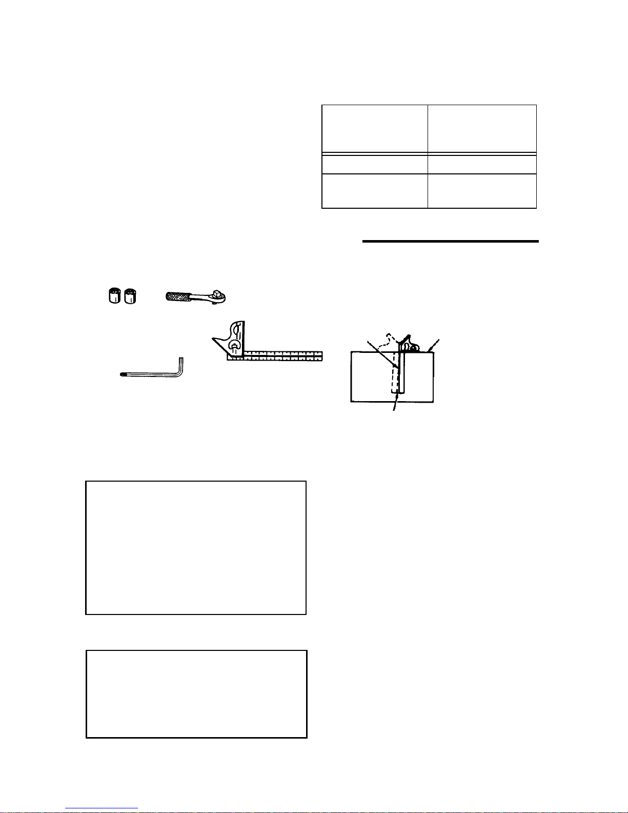
Tools Needed
Combination Square Must be True
Draw Light
3/4" or 19mm, 12mm
Socket
and Socket Wrench
Combination Square
Combination Wrench,
1/4" Hex “ L” W rench
with #2 Phillips tip
(supplied)
Line on Board
Along this Edge
Should be no Gap or Overlap when Square
is Flipped Over i n Dotted Position
Length
110-120V
0-25 Ft.
26-50 Ft.
Wire Sizes
Requiredfor120V
(A.W.G.)
14
12
Straight Edge of
Board 3/4" Thick
This Edge Must
be Perfectly
Straight
Unpacking
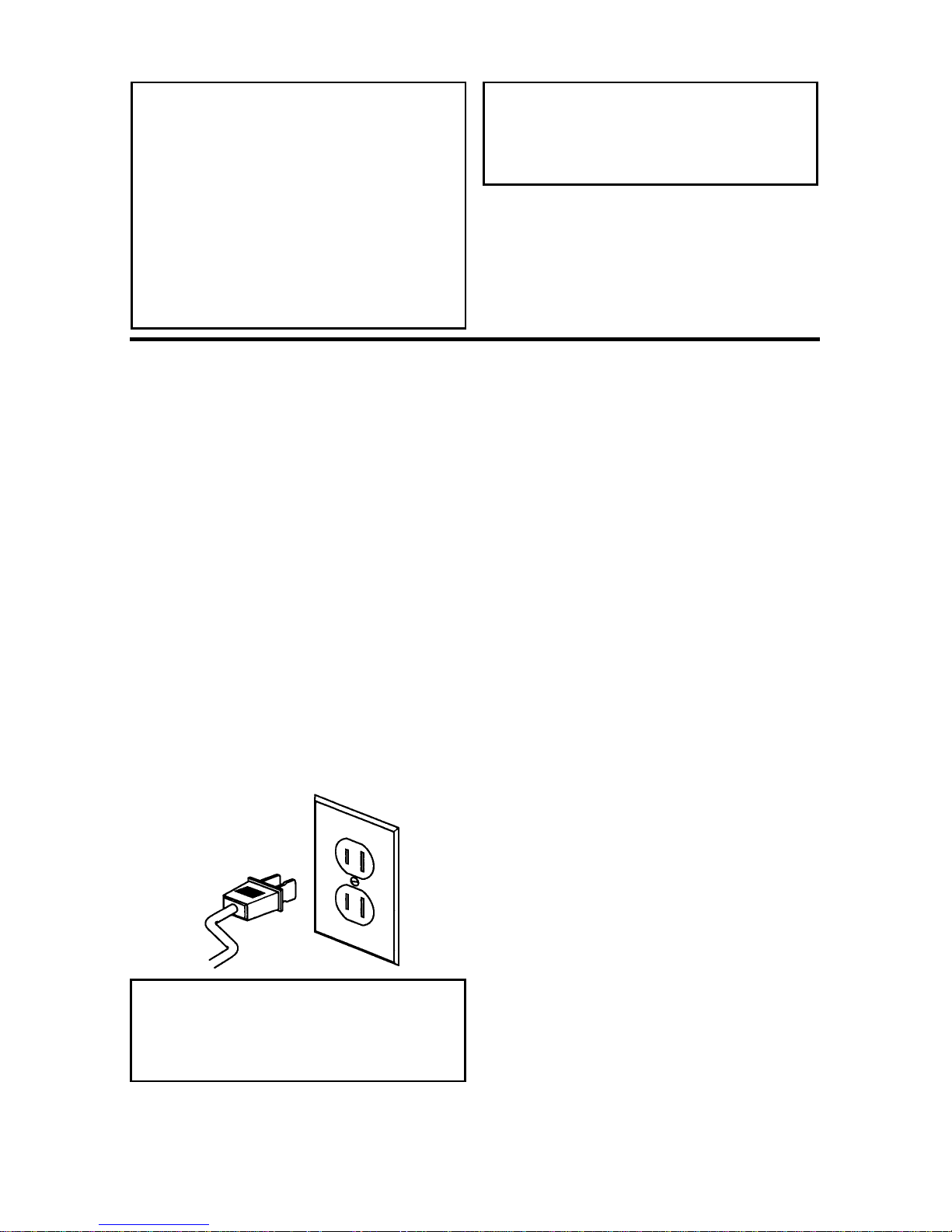
WARNING: To reduce the risk of
injury from un expected starting
or electrical shock, do no t plug
the power cord into a power
source outlet during unpacking
and assembly. This cord must
remain unplugged whenever you
are working on the saw.
ThisMi ter Saw is shipped completein one
box.
WARNING: Although co m pact,
this saw is heavy. To reduce the
risk of back injury, get help
whenever you have to lift the
saw.
1. Remove t he miter saw from the carton
by lifting the saw with the carrying handle.
1. Place the saw on a secure, stationary
work surface and look the saw over
carefully.
List of Loose Parts
NOTE:Before beginning assembly, check
that all parts are included. If you are missing any par t, do not assemble t he saw. Emailus atinfo@ridgidwoodworking.comif
any p arts are damaged or missing.
Sometimes small parts can get lost in
packaging material. Do not t hrow away
any packaging until saw i s put together.
Check packaging for missing parts before
contacting RIDGID. A complete parts list
(RepairParts) is at the end of the m anual.
Use the list to identify the number of the
missing part.
10
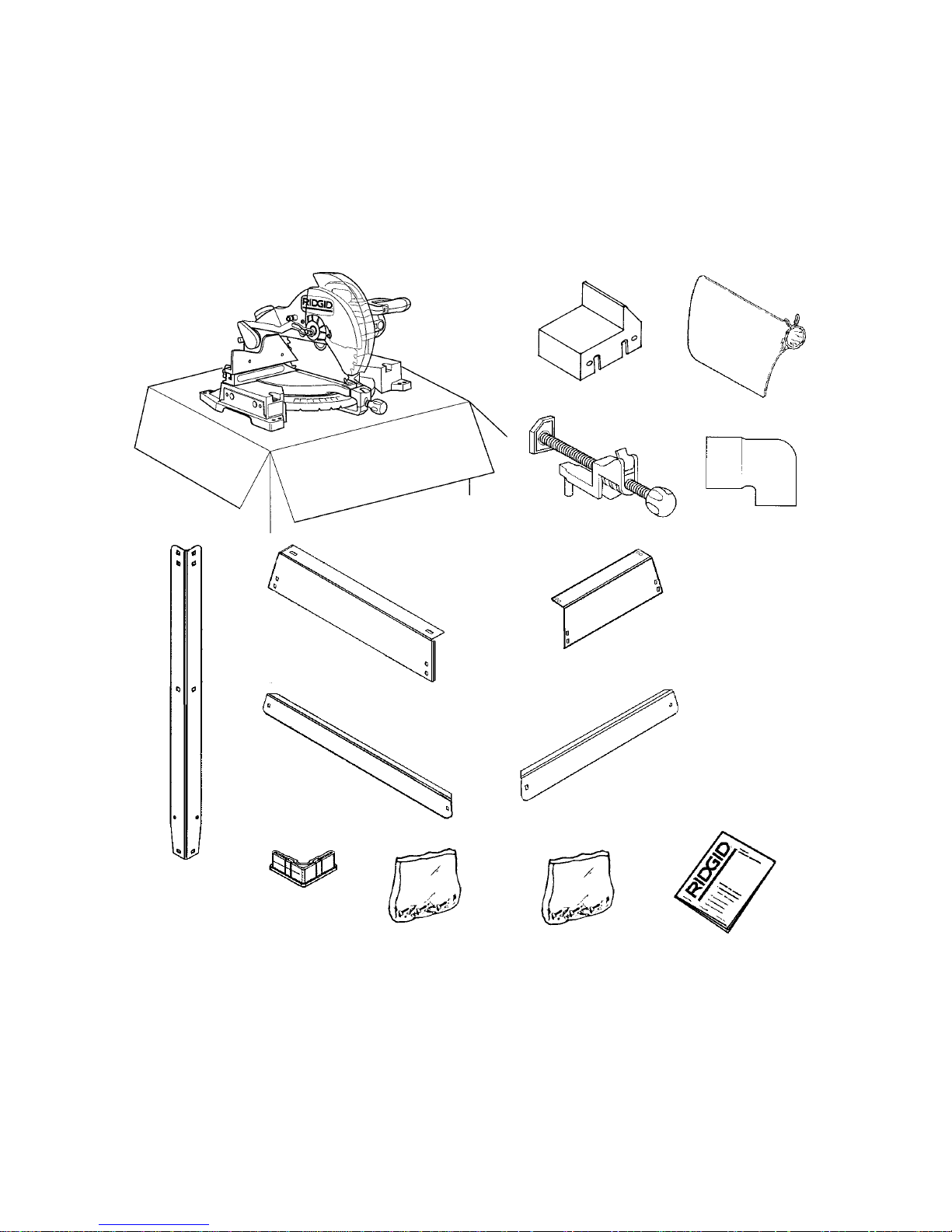
The following parts are included:
Part or Assembly Qty.
A Basic Saw Assembly...........................1
B Table Extension...................................1
C Dust Bag .............................................1
D Work Clamp ........................................1
E Dust Elbow..........................................1
F Leg ......................................................4
G Long U pper Stiffeners.........................2
A B C
Part or Assembly Qty.
H Shor t U pper Stiffeners........................2
J Long Lower Stiffeners.........................2
K Short Lower Stiffeners ........................2
L Foot (In Parts Bag) ............................. 4
MBag, Extension Hardware ................... 1
N Bag, Legset Hardware........................ 1
O Owners Manual................................... 1
DE
FG H
JK
LM N O
11
Assembly
WARNING: For your own safety,
never connect plug to power
source outlet until all assembly
steps are complete, and you
have read and u nderstood the
safety and o perational instructions.
Assembling and Aligning the Table
Extension
1. Locate the table extension. Locate the
bag assembly with the two cap screws
and two washers.
1. Place the two bolts and washers
throughthe holes in the table extension
and fasten onto the end of the table.
Finger tighten only.
2. Use a straight edge to align the table
extension to both the fence and base of
the saw as shown.
3. Using the 1/4" hex end of combination
wrench securely tighten the two cap
screws.
Lock Pin
Table Extension
Washer
Cap Screws
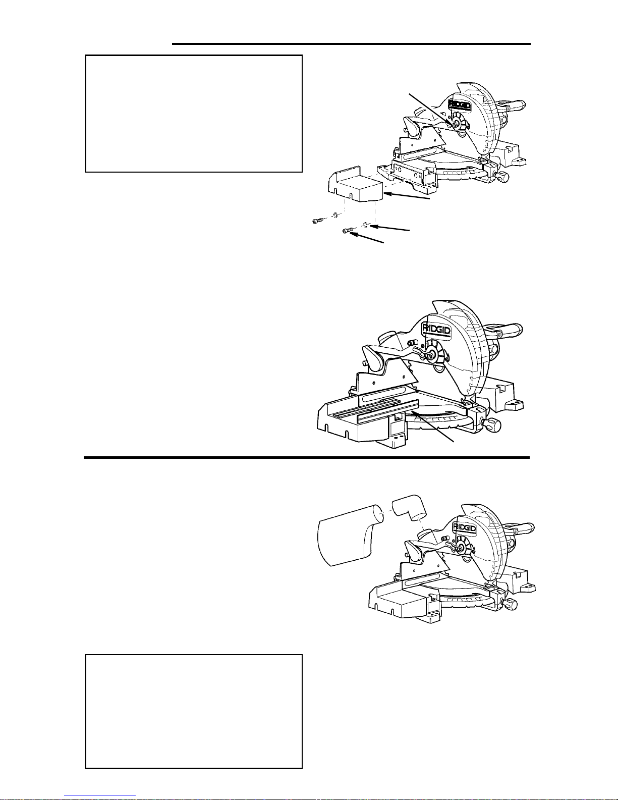
Attaching Dust Elbow and Dust
Bag
Place t he dust elbow into the 2-1/2 inch
dust port at the rear of the saw.
To attach the dust bag squeezethe spring
clamp on the bag and place it over the
dust elbow.
If desired a 2-1/2 inch wet/dry vac hose
may be inser ted into the dust port or into
the elbow.
If desired, the dust bag may be attached
directly to dust por t on saw.
WARNING: To reduce the risk of
injury from thrown sawdust and
wood chips, never operate saw
without dust bag, dust elbow, or
vac hose installed. Always direct
elbow away from bystanders and
operator.
Straightedge
12
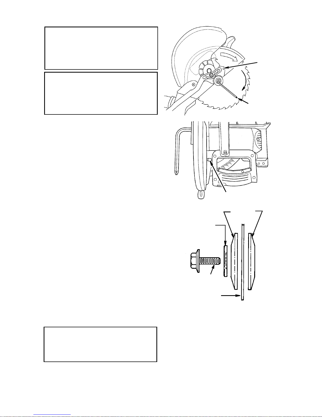
Installing or Removing the Blade
WARNING: To reduce the risk of
injury from a thrown workpiece
or thrown piec es of blade, do not
use a blade larg er or smaller than
12" diameter.
WARNING: To reduce the risk of
injury from un expected starting,
unplug the saw whenever you
are removing or installing the
blade.
1.Unplug the saw from the outlet.
2. Rotate the lower plastic guard by
hand. Loosen, but do not remove, the
cover plate stop screw using the Phillips end of c ombination wrench.
3.Lift the lower guard up and tilt the
lower guard assembly back so the
arbor screw is exposed.
4.Find the arbor lock between the upper
guard and the miter saw handle. Fit 1/
4” hex end of combination tool in arbor
screw or use 1/2” box end wrench.
5.Press the arbor lock and hold i t in
firmly while turning the wrench clockwise. The arbor lock will engage after
some turning of the wrench.
NOTE: The arbor screw has a left hand
thread. This helps prevent unwanted
loosening of the arbor screw during normal operation.
6. Remove the arbor screw, arbor washer,
outer blade collar , and the blade.
NOTE: Pay attention to pieces removed,
noting their position and direction they
face (see illustration). Wipe the blade collars clean of any sawdust before installing
the new blades.
CAUTION: To reduce the risk o f
cuts from extremely sharp teeth:
Wear gloves when instal ling or
removing saw blade.
See cautions in “Using Carbide Tipped
Blades” section concerning inspection,
use, and selection of carbide tipped and
other sawblades.
Stop
Screw
Loosen
Arbor Lock
Blade
Blade
Washer
(Hollowed Side
Toward Blade)
Arbor screw
(Left Hand Thread)
Sawblade
7.Install the new 12" blade (see recommended accessory list). Make sure
the rotation arrow on the blade
matches the clockwise rotation arrow
on the upper guard.
8.Install the outer blade collar, blade
washer and arbor screw. Press t he
arbor l ock and turn the combination
wrench or the 1/2" wrench counter
clockwise to secure the blade. Tighten
arbor screw using moderate force, but
do not overtighten.
Collars
13
Assembly (continued)
9.Lower the lower blade guard until the
slot in cover plate rests all the way
down on the cover plate stop screw.
Tighten the screw with the Phillips end
of the combination wrench.
DANGER: Never use saw withou t
guard cover pl ate securely in
place . It keeps the arbor screw
from falling out if it accidentally
loosens, and prevents the spinning blade from coming off the
machine .
10.Be sure the arbor lock is released so
the blade turns freely.
NOTE: The arbor lock can be damaged
by improper use. If the arbor lock will not
hold, lower the blade down on to a scrap
piece of wood positioned against the
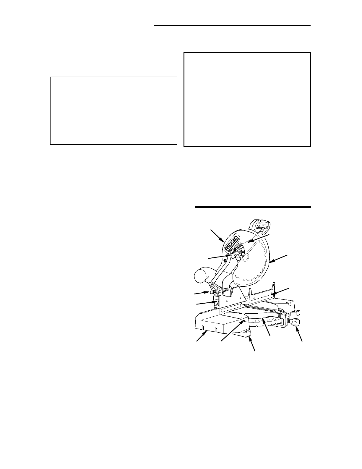
Getting to Know Your Miter Saw
fence. This will serve as an alternate locking means.
WARNING: Make sure th e collars
are clean and properly arranged.
After installing a new blade,
make sure the blade clears the
table slot at the 0° and 45° bevel
positions. Lower the blade into
the table slot and check for any
contact with the b ase or turn
table structure. If blade contacts
table, seek authorized service.
1.Lower Blade Guard - The blade
guard helps protect your hands from
the blade in the raised position. To
reduce the risk of binding on the workpiece, it retracts as the blade is lowered.
2.The Repeat-A-Cut™ - Surface allows
pencil marks to be made and easily
erased for duplicate cuts.
3.Miter Lock Knob - The miter lock
handle securely locks the miter saw at
a desired miter angle. Index points
have been provided on right and left
for 0, 15°, 22.5°, crown molding (CM)
and 45°.
4. Table - Sits in base, supports pivot
and allows for approximately 49° miter
left and right.
5.Base - Supports table, holds accessories and allows for work bench or leg
set mounting.
6. Left Extension Table - Helps to support long workpieces.
7. Sliding Fence - Slides left/right to
provide maximum support for the
workpiece.
10
9
Cover Plate
Stop Screw
1
2
8
7
~
(21-Clamp
6
Mounting Hole)
8.Lock Pin - The miter saw can be
lockedintheloweredpositionforcompact storage.
9.Cover Plate - Holds the lower guard
and is attached to upper guard. Prevents the arbor screw from backing
out when properly fastened.
10.Upper Blade Guard - Supports the
motor, handle, switch, blade and lower
guard.
4
3
5
14
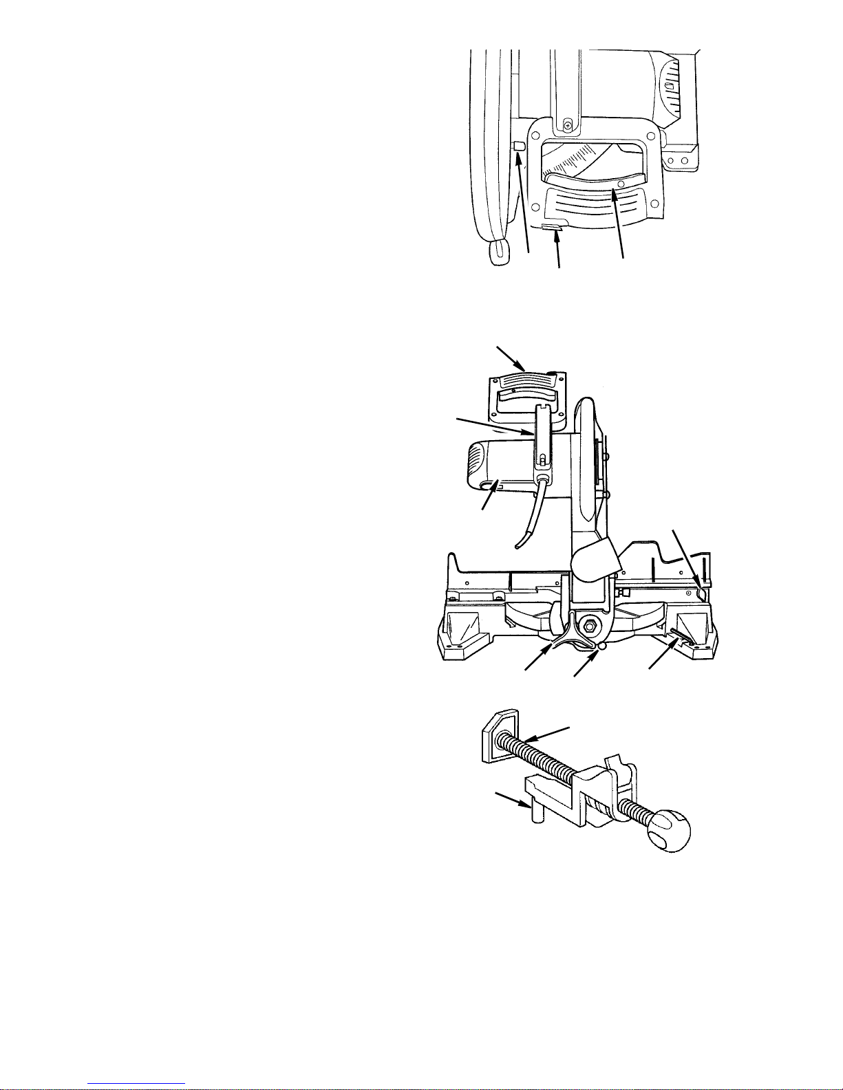
11.Arbor lock - Allows the user to keep
blade from rotating while tightening or
loosening arbor screw during blade
replacement or removal.
12.Switch Interlock Button - Prevents
trigger switch from being accidentally
engaged.
13.On/Off Trigger Switch - To start the
tool, depress switch interlock button
with right thumb or palm of ei ther hand
and then squeeze the trigger. Release
the trigger to stop the miter saw. Install
padlock through the hole in the trigger
to prevent unauthorized use.
14.Sliding Fence Locking Knob - Locks
fence at correct cutting position.
15.Combination Wrench - Used for 1/4"
hex and Phillips head screw adjustments.
16.Bevel Index Pin - This three position
pin provides a 0° and crown molding
bevel stop when pushed all the way in.
Inthemiddlepositiona0°and45°
bevel stop is pr ovided. Pull the pin all
the way out and the stops can be
over-ridden allowing -2° to 47° bevel
capacity.
17.Bevel Lock Knob - Locks the miter
saw at a desired bevel angle.
18.Warning Label
19.Carrying Handle - This handle is built
into the unit to move it from one location to another. Before attempting to
pick up the unit by the carrying handle
always lock the miter saw power head
in the down position using the lock pin.
Make sure the miter lock and bevel
lock knobs are tight.
20.Miter Saw Handle - The saw handle
contains the tr igger switch with a padlock, l ocking hole to prevent unauthorized use. The blade is lowered into
the workpiece by pushing down on the
handle. The saw will return to its
upright position when the handle is
released, unless the handle lock pin is
engaged.
11
12
13
FrontofSaw
20
19
18
17
16
14
15
21
Pin
21.Workpiece Clamp - Helps to hold
workpiece in position for precise cutting. Quick release allows easy movement for workpiece wi dth adjustment.
Pin of clamp fits in either hole in front
of base.
15
Alignment (Adjustments)
WARNING: Cut material can b e
thrown. Eyes can be perm anently
damaged. Wear your safety goggles.
Spring
NOTE:Before this saw is aligned or used,
a kerf must be cut into the table i nsert at
0° bevel. Our Quality Control Audit Procedure requiresus to cut through the inser ts
before they leave our factory.
To cut through an uncut insert:
1. Plug in the power cord.
1. Tur n the saw on by actuatingthe trigger
switch.
2. Lower the blade to full depth while cut-
ting through the table insert.
3. Release the trigger switch and allow
the blade to come to a complete stop.
4. Repeat this procedure at 45° bevel.
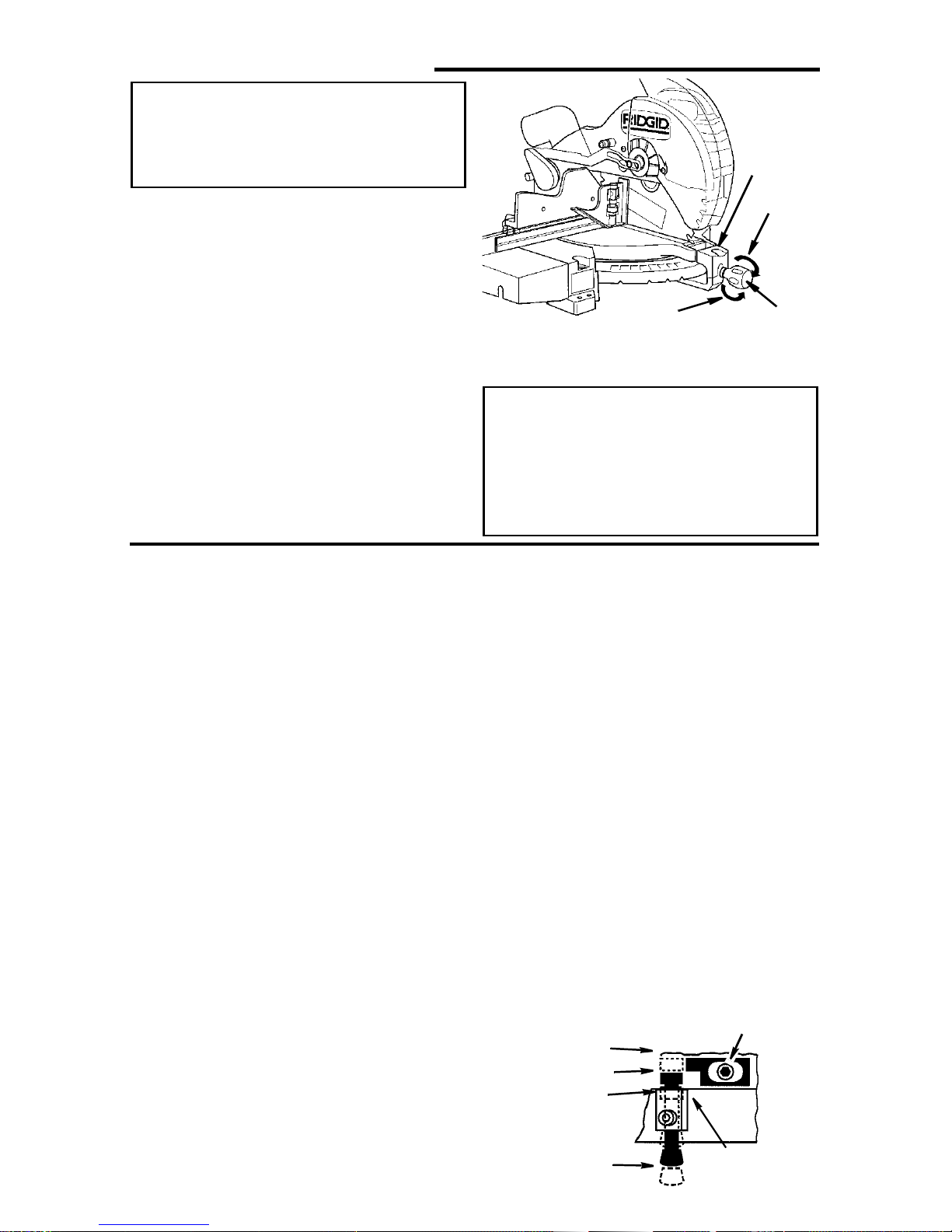
Step One: Blade Square to Table (Bevel Alignment)
NOTE: The miter saw was assembled,
aligned, and inspected before shipment.
Alignment should be checked and any
adjustments made to insure accurate cuts.
1. Check miter lock knob setting. The
miter lock knob should be at the 0°
position. To reset the miter angle, turn
the miter lock knob counter clockwise
and press down the indexspring, move
to 0° miter and retighten knob.
2. Lower the blade and engage the lock
pin.Use a combination squareto check
blade squareness to table. If the blade
does not contact the full length of the
square,(see illustration) follow the
alignment procedure.
a. Loosen bevel lock knob.
b. Grasping carrying handle, move the
cutting head left or right until blade
makes contact with the full length of
the square.
NOTE: If you cannot get to 0° bevel,the
bevel stop may be in your way. Adjust the
bevelstop(SeeStepd)soyoumay
achieve 0° bevel.
c. Tighten the bevel lock knob.
d. Loosen the 0° bevel stop mounting
Tighten
Loosen
5. Unplug the power cord before starting
alignment procedure.
Handle
WARNING: To reduce the risk of
injury from unexpected starting
or ele ctrical shock, do not plug
the saw in. The power cord must
remain unplugged whenever you
are working on the saw.
screw and push the stop against the
pin. Retighten the stop mounting
wrench. Sl ide the indicator under the
Phillipsheadscrewtolineupexactly
with the 0° bevel mark on the bevel
scale. Retighten the indicator screw.
e. Loosen bevel lock knob and tilt the
power head to 45° bevel and check
the 45° bevel stop. The bevel indicator should be on the 45° mark, the
45° bevel stop should be in full contact with the 45° bevel stop screw ,
and the blade should contact the full
length of the square. This adjustment
sets the 45° and crown molding
stops.
3. If adjustmentis necessary, repeatsteps
2a - 2d for the 45°/crown molding bevel
stop.
Bevel Stop
Mounting Screw
0°, CM Index
0°, 45° Index
By-Pass
Index/
By-Pass P in
16
Bevel Index
Mechanism
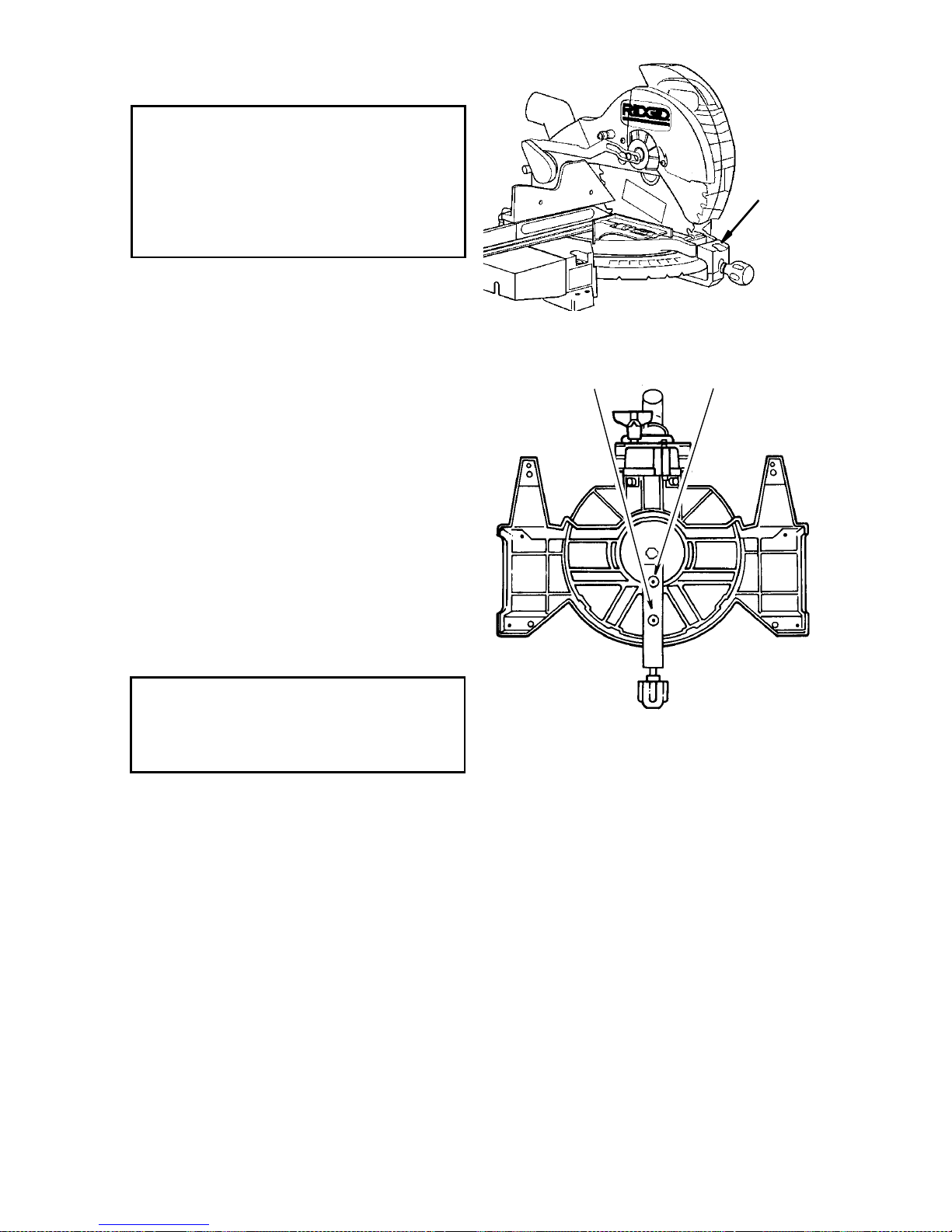
Step Two: Blade Square to Fence
(Miter Alignment)
WARNING: To reduce the risk of
injury from un expected starting
or electrical shock, do no t plug
the saw in. The power cord must
remain unplugged whenever you
are working on the saw.
Adjust Bl ade Square to Fence:
1. Lower the blade and engage the lock
pin. Use a combination square. Place
the square against the fence and next
to the blade as illustrated. Locate the
square properly so it does not contact
the set in t he teeth of sawblade, giving
an inaccurate reading. The sawblade
should contact the full l ength of the
square.
1. If blade contacts full length of square,
no alignment is necessary, skip a-f
below. If blade is not square to the
fence, follow the al ignment procedure.
a. Loosen miter lock knob a half turn.
The saw power head should still be
secured in the lowered position by
the lock pin.
Miter
Indicator
Miter Arm
Cap Head Screws
CAUTION: To keep from losing control of the unit, steady the base with
one hand while loosening the two
bolts with the other hand.
b. With the unit securely resting on a
large stable surface, tilt the unit by
lifting up on one side or the other of
the base. Using combination wrench
supplied, loosen the two miter arm
cap head screws on the underside of
the turn table.
c. Return the saw to its normal resting
position. Make sure the miter lock
knob is loose but do not release the
index spring.
d. Use the miter saw knob to move the
table so that the blade contacts the
full length of t he square. Watch out
fort ooth set. Turn the miter lock knob
clockwise to lock saw square to
fence.
e. Tilt saw as in Step b and tighten cap
head screws.
f. Recheck blade squareness to fence
and readjust if necessary.
Adjust Miter S cale Indicator
1. Through the hole in front of t he table
insert, loosen the Phillips screw that
holds the Vernier indicator in place.
1. Reposition the indicator to align it with
0° mark, and retighten screw.
17

Alignment (Adjustments) (continued)
Step Three: Pivot Adjustment
NOTE: This adjustment was made at the
factory and normally does not require
readjustment.
Arm Pivot M ovement
1. Make sure the see through lower guard
is rotated closed and is resting against,
or very close to,the r ubber stops. If not,
see “Lubrication” section.
Bevel Pivot Movement/Adjustment
Check that miter saw bevels easily by
looseningthe bevell ock handleand tilting
the power head to the left. NOTE: At least
one thread of the pivotbolt should stick
out past the hex lock nut.
1. If movement is tight or there is loose-
Assembling Leg Set
1. Locate the following parts:
4 Legs
2 Long Upper Stiffeners
2 Short Upper Stiffeners
2 Long Lower Stiffeners
2 Short Lower Stiffeners.
2. From the leg set hardware bag find the
following:
4 Feet
24Carriage Bolts 5/16-18 x 5/8
24Flange Nuts 5/16-18
NOTE: Hardware not shown actual size.
3. Assemble the stand as shown. Make
sure the legs go inside the upper stiffeners. Make sure the legs go outside
the lower stiffeners. Make sure the long
upperstiffenersgo overthe short upper
stiffeners.
4. Only finger tighten nuts at this time.
ness in the pivot, do the following
adjustment procedure:
a. Loosen t he bevel lock handle.
b.Turnthehexlocknutwitha3/4"or
19mm socket and socket wrench.
Recheck bevel movement of the miter
saw. Readjust if necessary.
Leg
Long Upper
Stiffener
Short Upper
Stiffener
Foot
Short UIpper
Stiffener
Leg
Long Lower
Stiffener
Bolt
Short Lower
Stiffener
Flange Nut
Long Upper
Stiffener
18
Long Lower
Stiffener
Foot
Short Lower
Stiffener
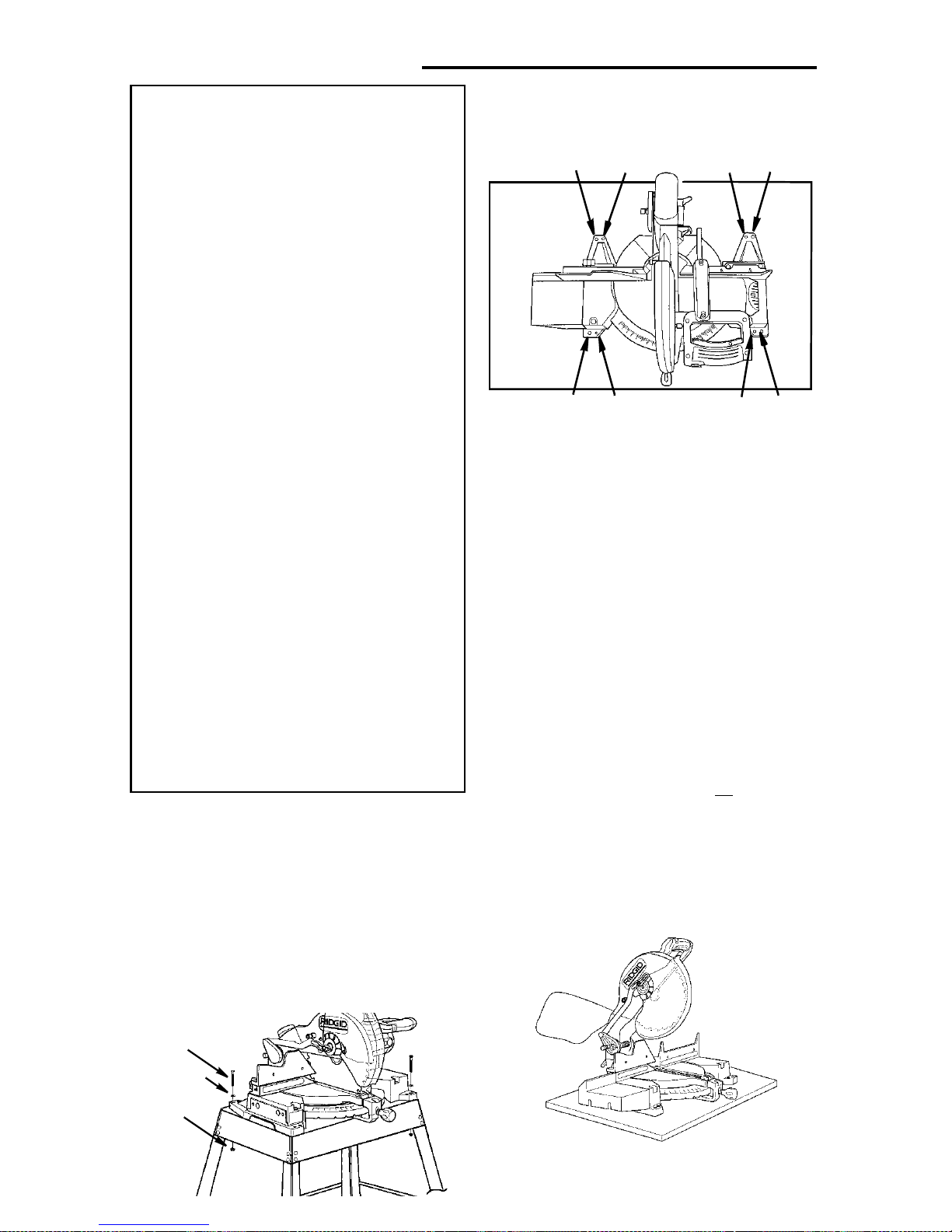
Mounting The Miter Saw
WARNING: To reduce the risk of
injury from un expected saw
movement:
a.Before moving the saw, lock the
miter and bevel knobs and lock
the power head in the lower
position. Unplug electric cord.
b.Toreducetheriskofback
injury , hold the tool close to
your body when lifting. Bend
your knees so you can lift with
your legs, not your back. Lift by
using the hand-hold areas at
each side of the bottom of the
base or by the carrying handle .
c.Never carry the miter saw by
the power cord or the trigger
grip of the plastic handle. Carrying the tool by the power
cord could cause damage to
the insulation or the wire connections resulting in electric
shock or fire.
d.Place the saw so other people
cannot stand b ehind it. Thrown
debris could injure people in
its path.
e.Place the saw on a firm, level
surfacewherethereisplentyof
room for handling and properly
supporting the workpiece.
f. Support the saw so the table is
level and the saw does not rock.
g.Boltor clamp the saw toitssupport.
Mounting Saw on Supplied Legset
1. Locate 4 bolts,4 washers and 4 nuts in
parts bag.
2. Position leg set at the desired location .
3. Mount the miter saw as shown wi th provided hardware. Only finger tighten
nuts at this time.
4. If necessary shift the leg set to adjust
for slightly unlevel floor.Securely
tighten all hardware.
Mounting Saw on Other Legsets or
Work Benches
B
Mounting Board or Work Surface
Place the saw in the desired location
either on a work bench or other recommended leg set. The base of the saw has
eight holes to mount the miter saw. Four
smaller holes for “drywall” screws are
labeled A. Fourholes for bolts are labeled
B (seeillustration).If t he sawis tobe used
in one location, permanently fasten it to
the work bench or leg set.
NOTE: When mounted on a large flat surface, t he miter saw table is 3 1/2" high. A
finished 4x4 or a supported 2x4 on edge
can be used as work support extension.
A
ABBA
B
A
Portable Applications
To mount the saw to a 3/4” piece of plywood, use 4, 1/4" bolt holes or
wallscrew holes. The mounting board can
then be clamped down t o prevent i t from
tipping. Plywood mount also helps protect
saw from damage during the rough handling associated with portable miter saw
usage.
the 4 dry-
Bolt
Washer
Nut
19

Safety Instructions for Basic Saw Operations
Before Each Use
Inspect your saw.
Disconnect The Miter Saw. To
reduce the risk of injury from accidental starting, unp lug the saw, before
changing the setup, changing the
blade or adjusting anything.
Compare the direction of rotation
arrow on the guard to the direction
arrow on blade. The blade tee th
should always point downward at the
front of the s aw.
Tighten the arbor screw.
Tighten the cover plate stop screw.
Check Damaged Par t s. Check for:
• Alignment of moving parts,
• Damag ed electric co rds,
• Binding of moving parts,
• Broken parts,
• Stable mounting
• Function of arm ret urn spring and
lower guard: Push the arm all the
way down, then let it rise up until it
stops by itself. Check the lower
guard to see if it closed fully. If it did
not, follow the instructions in t he
Trouble Shooting section.
• Other conditions that may affect the
way the miter saw works.
Keep G uards In Place,inworking
order, and in proper adjustment.
If any part of this m iter saw if missing,
bent, or broken in any way, or any
electrical par ts don’t work, turn the
saw off and unplug it. Replace damaged, m iss ing, or failed parts before
using the saw again.
Maintain Tools With Care. Keep the
miter saw clean for best and safest
performance. Follow instructions for
lubricating. DON’T put lubricants on
the blade while it’s s pinning.
Remove Adjusting Keys And
Wrenches from tool before turning it
on.
To Reduce the Risk of Injury From Jams, Slips Or Thrown Pieces
• Use Only Recommended A c cessories. (See “Accessory” section
within.) Consult this Owner’s manual
for recommended acc es s ories. Follow the instructions that come with
the accessories. The use of
improper accessories may cause
risk of injur y to person s.
• Choose the right 12-inch diame ter
blade for the material and the t y pe
of cutting you plan to do.
• Make sure the blade is shar p,
undamaged and properly aligne d.
With the saw u nplugged, push t he
power-head all the way down. Hand
spin the blade and che ck for clearance.
• Make sure the blade and arbor col-
lars are clean.
• Make sure the collars' recessed
sides are facing the blade.
• Us ing 1/4” hex end of combination
wrench (supplied) or 1/2-inch box
end wrench, make sure the arbor
screw is firmly tightened.
• Make sure all clamps and locks are
tight and there is no excessive play
in any parts.
• Keep work area clean. Cluttered
areas and benches invite accidents.
Floor must not be slippery.
To reduce the risk of bur ns or other
fire damage, never use the miter saw
near flammable liquids, vapors or
gases.
20
Plan Ahead To Protect Your Eyes, Hands, Face and Ears
Know your miter saw. Read and
understand the owner’s manual and
labels affixed to the tool. Lear n its
application and limitations as well as
the specificpotential hazards pecul iar
to this tool.
To red uce the ri sk of injury from accidental contact with moving parts,
don’t do layout, assembly, or setup
work on the miter saw while any parts
are moving.
Reduce the Risk of Accidental
Starting. Make sure switch is “O FF”
before plugg ing miter saw into a
power outlet.
Plan your work.
Use The Right Tool. Don’t force tool
or attachment to do a job it was not
designed to do. Use a different tool
forany workpiece that can’t be held in
a solidly braced, fixed position.
CAUTION: This machine is n ot
designed for cutting ferrous metals (steel , iron and iron b ased
metals). Use this miter saw to cut
only wood, wood like products or
soft me tals like aluminum. Other
material may shatter, bind on the
blade, o r create oth er dan gers.
CAUTION: W hen cutting any metals, sparks or hot fragments
could cause a fire . To avoid this,
disconnect any dust collecting
bag or hose from the miter saw,
and remove all traces of wood
dust from inside dust traps in the
miter saw.
Dress For Safety
The operation of any powermiter saw can
throw foreign objects into the eyes. This
can result in permanent eye damage.
Wear safety goggles (not glasses) that
comply wi th ANSI Z87.1 (or in Canada
CSA Z94.3-99) shown on package.
Everyday eyeglasses have only impact
resistant lenses. They are not safety
glasses.Safety goggles ar e available at
many local retail stores. Glasses or goggles not in compliance with ANSI or CSA
could ser iously hurt you when they break
• Do not wear loose clothing, gloves,
neckties or jewelry (rings, wrist
Preparing to Make the Cut
Inspect Your Workp iece. Make sure
there are no nails or foreign objects in
the part of the workpiece to be cut.
Plan your work to avoid thrown
pieces caus ed when the workpiece
binds on the blade and is torn from
your hands.
Plan the way you will hold the work-
watches) T hey can get caught and
draw you into moving parts.
• Wear nonslip footwear.
• Tie back long hair.
• Roll long sleeves above the elbow.
• Noise levels vary widely. To reduce
the risk of possible heari ng d amage,
wear ear plugs or muffs when using
miter s aw for hours at a time.
• For dusty operations, wear a dust
mask along with s afety goggles.
piece from start to finish.
Avoid awkward operations and hand
positions where a sudde n slip could
cause f ingers or hand to move into
the blade.
Don’t Overreach. Keep good footing
and balance.
21

Safety Instructions for Basic Saw Operations (con’t.)
Keep your face an d body to one side
of sawblade, out of line with a possible throwback.
Cut only one workpiece at a time.
Never cut Freehand:
• Brace your workpi ec e solidly
against the fence and ta ble top so it
will not rock or twist during the cut.
• Make sure there’s no debris
between the workpiece and its supports.
• Make sure no gaps between the
workpiece, fence and table will let
the workpiece shift after it is cut in
two.
•Keepthecutoffpiecefreetomove
sidewaysafter it'scutoff.Otherwise,
it could get wedged against the
blade and c ould be thrown violently.
• Clear everything except the wor kpiece and related support devises
off the table before turning the miter
saw on.
• Secure Work. Use clamps or a vise
to help hold t he work wh en it’s practical.
Use extra caution with large , ver y
small or awkward workpieces:
• Use extra supports (t ables, saw
horses, blocks, etc.) forany workpieces large enough to tip when not
held down to the table top.
• Never use another person as a substitute for a table extension, or as
additional support for a work piece
that is longer or wider than the bas ic
miter saw table or to help feed, sup port or pull the workpiece.
too small to let you easily hold the
work while you keep the thumb side
of your index (pointer) finger against
the outside edge of the fence.
• When cutting irregularly shap ed
workpieces, pl an your work so it will
not slip and pinc h the blade and be
torn from your hands. A pie ce of
molding, for example, must lie flat or
be held by a fixture or jig that will not
let it twist, rock or slip while being
cut.
• Properly support round material
such as dowel rods, or tubing. They
have a t endency t o roll while being
cut, causing the blade to "bite." To
avoid this, always use a fixture
designed to properly hold your
workpiece.
WARNING: If planning to cut aluminum or other non-ferrous metals: Und er adverse conditions,
thebladecangrabandthrowthe
workpiece suddenly and unexpectedly. To reduce the risk of
injury ,follow all applicable safety
instructions, as you nor mally
would, and:
• Use only sawblades specifi-
cally recom m ended for non-ferrous metal cutting.
• D o not cut m etal workpieces
that must be hand held. Use
auxiliary clamps or other
equipment as needed.
• Cut non-ferrous metals only if
you are experienced or under
the supervisi on of an experienced person.
• Do not use this saw to c ut pieces
22

Whenever Saw Is Running
WARNING: Don't allow familiarity
(gained from frequent u se of
your miter saw) cause a carele ss
mistake. A careless frac t io n of a
second is enough to cause a
severe injury.
Before starting your cut, watch the
miter saw while it runs. If it makes an
unfamiliar noise or vibrates a lot, stop
immediately. Turn the saw o ff. Unplug
the saw. Do not restart until finding
and correcting the problem .
Keep Children Away. Keep all visitors a safe distance from the miter
saw. Make sure bystanders are cl ear
of the miter saw and workpiece.
Never confine the piece being cut
off. Never hold it, clamp it, touch it, or
use length stops against it while the
blade is spinning. It must be free t o
move sideways on its own. If confined, it could get wedged against the
blade and th rown violently.
Let the blade reach full speed
before cutting. This will help reduce
the risk of a thrown workpiece.
Don’t Force Tool. It will do the job
better and safer at its designed rate.
Feed the saw into the work piece only
fast enough to let t he blade cut without bogging down or binding.
Before free in g jammed m aterial:
• Turn miter saw “OFF” by releasing
trigger switch.
• Wait for all moving parts to stop.
• Unplug the mi ter saw.
After finishing a cut:
• Keep holding the power head down.
• Release t he switch, and wait for all
moving parts to stop before moving
your hands or raising power head.
• If blade doesn’t stop within 6 seconds, unplug the saw and follow the
instructions in the Trouble Shooting
section for fixing the blade brake
before using the saw again.
Before Leaving The Saw:
Never Leave Tool Running Unattended.Turnpoweroff.Waitforall
moving parts to stop.
Make workshop child-proof. Install
a padlock through t he hole provided
in the trigg er to prevent unauthorized
usage. Lock the shop. Disconnect
master switches. Store tool awayfrom
children and ot hers no t qualified to
use the tool.
23
Basic Saw Operations
WARNING: For your convenient
use, your saw has a blade brake .
The brake is not a safety device.
Never rely on it to replace proper
use of the guard on your saw. If
the blade does not stop within 6
seconds, unplug the saw and follow the instructions in the Trouble Shooting section for fixing
the brake before using saw
again.
Body and Hand Position
• Never place hands near cutting area.
Place hand at least 4" from path of
blade.
• Hold workpiece firmly to the fence to
prevent movement toward the blade.
• When holding the workpiece to t he left
side of the blade, always use your left
hand. Use your right hand to hold the
workpiece to the right side of the blade.
• Before making a cut, make a “dry r un”
with the power off so you can see the
Miter Scale Usage
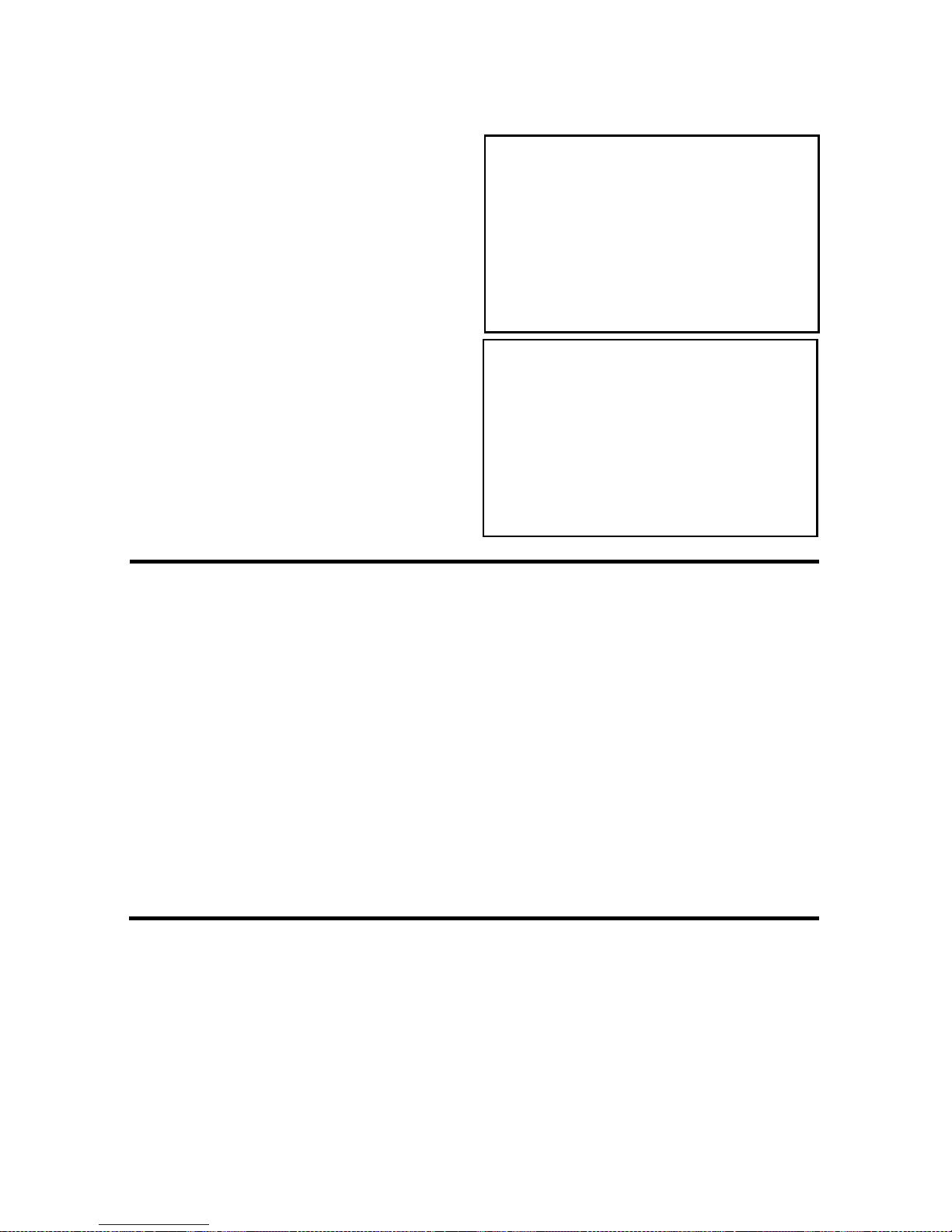
Vernier Miter Scale Operation:
The Vernier miter scale can quickly and
Miter Scale
5°
5-1/4°
path of the blade.
• Keep hands in position until trigger has
been released and the blade has completely stopped.
WARNING: Do not try to cut
short pieces, you cannot properly support the workpiece and
keep your hold down hand the
required distance from the blade.
accurately help the user to adjust the saw
to any 1/4° increment as illustrated below.
Vernier
Miter Indicator
5-1/2°
5-3/4°
Indicator over
5° scale mark
1/4° Indicator line
over 6° scale mark over 7° scale mark
1/2° Indicator line
24
3/4° Indicator line
over 8° scale mark
Sliding Fence
When beveling the blade to the left t he
fence may have to be repositioned.
Loosen the fence locking knob and slide
the fence to the left. Adjust the fence as
close to the guard and link as possible to
provide maximum suppor t for the workpiece. Securely tighten knob and make a
dry run with the saw off to check for clearance between the fence and guard. Af ter
completing bevelcut(s) remembert o slide
the fence back t o the right.
Miter Cut
When a miter cut is required, loosen miter
lock knob, depress the index spring and
move the saw to the desired angle.
Retighten miter lock knob.Move with the
handle to the miter angle to make the cut.
Bevel Cu t
When a bevel cut is required, loosen
bevel lock knob. Tilt the blade to desired
bevel angle. Retighten bevel lock knob.
Stand to the left side of the handle to
make the cut.
The bevel stop pin, foundat the rear of the
saw, has three positions as shown. For
most cuts the 0 - 45° middle position is
used. Push the pin all the way i n to utilize
the 0 - CM position when cutting crown
molding. Pull the pin all the way out to
allow the bevel adjustment to go beyond
the 0° and 45° stops.
Move Feet
With Miter
Saw
0°, CM Index
0°, 45° Index
By-Pass
25
Index/
By-Pass Pin
Bevel Index
Mechanism
Basic Saw Operations (continued)
Compound Cut
When a compound cut i s required, select
the desired bevel and miter positions.
Move with the handleto the miter angle t o
make the cut.
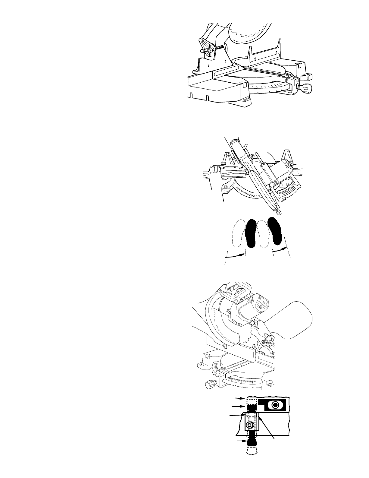
Cutting Compound Miters on
PictureFramesandBoxes
A compound miter is a cut requiring both
a miter setting and bevel setting. A compound miter is used for making frames or
boxes that have sloping sides and are
wide at one end and narrow at the opposite end. Compound miters are “tricky” to
makebecause the mitersetting and bevel
setting are directly related to each other.
Every time the miter setting is changed
the bevel setting must also be adjusted;
likewise every adjustment to bevel
requires a corresponding adjustment to
miter. Because it may take several tries to
obtain the desired angle, it is advisable to
make test cuts on a scrap piece of material.
Compound Cut Box
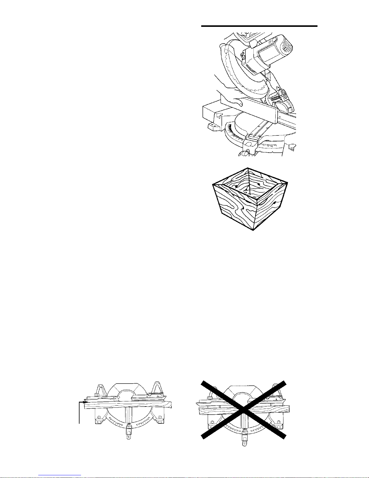
Cutting Bowed Material
Before cutting a workpiece, check to
make sure it is not bowed. If it is bowed
the workpiece must be positioned and cut
as illustrated. Do not position workpiece
incorrectly or try to cut the workpiecewith-
Hold workpiece tight
against fence so
thereisnogap
Correct
out the support of the fence.This will
cause pinching of the workpiece on t he
blade. The workpiece could suddenly
jump or move and your hand could hit the
blade.
Incorrect
26
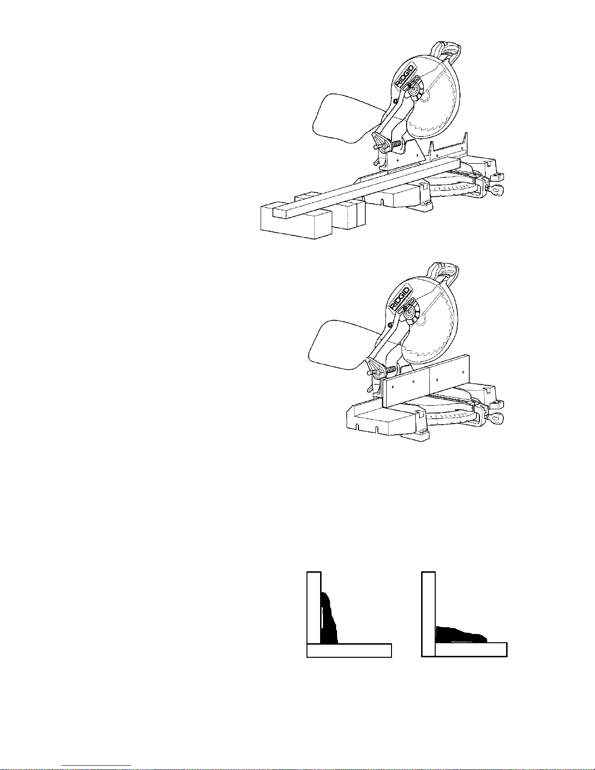
Workpiece Support
Long pieces need extra supports. The
supports should be placed along the
workpiece so the workpiece does not sag
and your hand holding the workpiece is
positioned4” or more from the blade path.
The support should let the workpiece
lay flat on the base and work table
during t he cutting operation.
NOTE: When mounted on a large flat surface, t he miter saw table is 3 1/2” high. A
finished 4x4 or a supported 2x4
on edge can be used as work support extension.
Auxiliary Fence
Certain unusual cuts may benefit from a
fence face extension due to the size and
position of the workpiece. Holes are provided in the fence to attach an auxiliary
fence. Get a straight piece of wood typically1/2 inch thick by 4-1/4 inches high by
23-1/2 or 28 inches long. To attach auxiliary fence, place the piece of wood on the
miter saw fence. Mark the hole locations
from the backside of the miter saw fence.
Drill .200”-.250” holes, then countersink
the holes on front of wood to receive #10
flat head screws. Attach the auxiliary
fence securely and make a full depth cut.
This wi ll create the blade slot. Check for
interference between the auxiliary fence
and lower blade guard. Correct any interference before proceeding. The auxiliary
fenceisusedwiththesawinthe0°bevel
position. If a bevel cut is desired, the auxiliary fence will have to be removed.
Cutting Base Moldings
Base moldings and many other moldings
can be cut on a miter saw. The set up of
the saw depends on your molding and
your application as shown. Always make
sure moldings rest firmly against fence
and table.
F
e
n
c
e
Miter Saw Table
(Miter at 45° (Miter at 0°,
Bevel at 0°) Bevel at 45°)
27
F
e
n
c
e
Miter Saw Table
Cutting Base Molding
 Loading...