

Page 1

'3
2:1(5·60$18$/
,1&+)/22502'(/
'5,//35(66
)RU<RXU6DIHW\
5HDGDOOLQVWUXFWLRQVFDUHIXOO\
6DYHWKLVPDQXDOIRUIXWXUH
UHIHUHQHFH
Part No. SP6431 Printed in China
Page 2
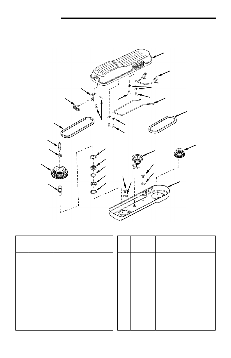
Repair Parts
Parts List for RIDGID 15" Drill Press
Model No. DP15500
Figure 1
1
2
22
21
7
4
4
6
4
19
18
13
14
17
16
Always order by Part Number - Not by Key Number
Key
Part No. Description
No.
829775
1
828814
2
828812
3
828932
4
828813
5
828811
6
816439-4
7
828919
8
817358-1
9
820241-5
10
* Standard hardware item - may be purchased locally.
Guard Upper
Link - Rear
Clamp - Rear Link
* Screw Pan Hd
M5.5 x 1.8-12
Link - Front
Clamp - Front Link
Belt Poly V 27"
Pulley Asm - Idler
* Screw Rd Hd Wash
M6 x 1.0
* Lockwasher Ext M6
15
14
13
9
10
Key
Part No. Description
No.
828818
11
828816
12
817537
13
817530
14
817536
15
821734
16
828849
17
821742
18
829688
19
816439-5
20
828820
21
828821
22
3
4
5
8
9
10
12
Pulley Asm - Motor
Guard Lower
Ring Retaining
Bearin g B all 2 0 mm
Spacer
Insert P u lley
Pulley Spindle
Nut Pulley
Cap Spindle
Belt Poly V 25"
Latch
Spring Latch
20
11
35
Page 3
36
49
55
48
56
50
52
28
51
37
41
27
42
36
43
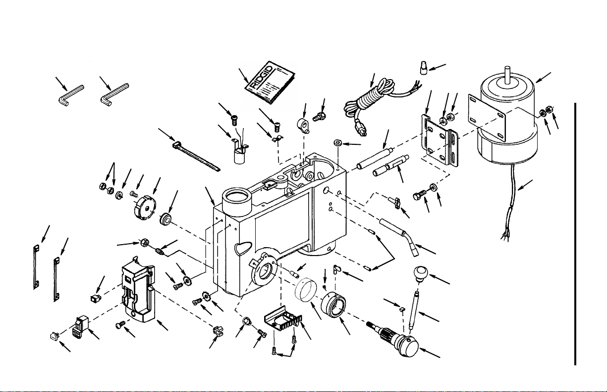
Parts List for RIDGID 15" Drill Press
Model No. DP15500
Figure 2
13
14
29
53
40
34
33
35
39
15
25
38
35
12
22
Repair Parts
11
6
78
9
10
3
2
16
18
17
21
1
5
3
4
47
46
45
44
30
54
43
26
25
32
31
24
20
20
23
19
Page 4

Repair Parts
Always order by Part Number -- Not by Key Number
Parts List for RIDGID 15" Drill Press
Model No. DP15500
Figure 2
Key
Part No. Description
No.
828929
1
820381-2
2
821063-2
3
828940
4
824026-7
5
817336-1
6
820383-8
7
820236-9
8
817495
9
817516
10
817330
11
828941
12
SP6431
13
817317
14
820381-4
15
817320
16
817494
17
821750
18
828904
19
826445
20
826441
21
817300
22
829590
23
828876
24
816743-4
25
826057
26
828880
27
821738-3
28
828917
29
* Standard hardware item - may be purchased locally.
• Any attempt to repair t his motor may create a hazard unless repair is done by a qualified service tec hnician.
Repair service is avai lable at your nearest Author ized Service Center.
• Motor
* Screw Hex Hd.
M8 x 1.25-20
* Washer M8 x 16 x 1.6
Cord Motor
* Nut Hex M8 x 1.25
Mount Motor
* Lockwasher 12mm
* Nut Hex M12 x 1.75
Support Motor Bracket
Support Motor Bracket
Connector Wire
Cord w/Plug
Owners Manual
Lever Adjustin g
* Screw Hex Hd.
M8 x 1.25-16
Knob Motor Adjusting
Handle Belt Tension
Screw Hex Soc. Set
M10 x 1.5-12
Hub Asm.
Rod
Knob
Guide Scale
Ring Depth Stop
Scale Depth
* Screw Pan Cr
M4 x 0.7 x 8
Pointer
Spring Asm.
* Nut Hex M12 x 1.5-8
Pin Stop
Key
Part No. Description
No.
30
31
32
33
34
35
36
37
38
39
40
41
42
43
44
45
46
47
48
49
50
51
52
53
54
55
56
828877
828963
820240-6
829595
820244
817343
828928
820378
820294
829689
829826
810506-3
829803
820241-4
828921
820240
829787
826122
829597
829597-1
828923
829690
820236-8
817308
820240-3
813317-6
813317-8
Holder Key Chuck
Lens Assembly
* Screw Pan Hd.
M5 x 0.8-12
Socket Bulb Asm.
* Screw Pan Hd.
M6 x 1.0-12
Lock Depth Screw
Bearing Pinion Shaft
Screw Soc Cap
M4 x 0.7-10
Washer Foam
Clamp Cord
Head Asm.
Tie Wire
Screw Hex Hd. Gnd.
M5 x 0.8
Lockwasher Ext. M5
Box Switch Asm.
* Screw Pan Hd.
M5 x 0.8-16
Switch Locking
Key Switch
Lead 3" Black
Lead 3" White
Switch Rocker
Washer 12mm ID Plain
* Nut Hex M10 x 1.5
Screw Sl. Set Fl Pt
* Screw Pan Hd
M5 x 0.8-6
Wrench Hex “L” 3mm
Wrench Hex “L” 5mm
37
Page 5

Repair Parts
Parts List for RIDGID 15" Drill Press
Model No. DP15500
Figure 3
10
1
2
3
4
5
9
6
8
7
Always order by Part Number - Not by Key Number
Key
Part No. Description
No.
1
2
3
4
5
817309
817310
817311
813480
817535
Lock Nut M17 x 1.0
Ring Locking
Washer
Bearing Ball 17mm
Gasket Quill
38
Key
Part No. Description
No.
Tube Quill
Key Chuck
Chuck
Spindle
Bearin g B all
10
6
7
8
9
828875
817339
817340
828908
817529
Page 6

Repair Parts
21
20
Parts List for RDIGID 15" Drill Press
Model No. DP15500
Figure 4
20
1
19
2
18
5
6
22
17
16
15
13
2
23
Key
Part No. Description
No.
817478
1
820245
2
821861-2
3
826439
4
821880
5
828927
6
821881-1
7
828870
8
813164-6
9
821754
10
828961
11
* Standard hardware item - may be purchased locally.
14
Collar Rack
* Screw Hex Soc. Set
M6 x 1.0-10
Support Table
w/Indicator
Crank (Includes Set
Screw)
Tube Column
Rack
Support Column
Tray, Back
Nut Hex M5
* Screw Hex Hd.
M10 x 1.5-40
Base
39
Key
No.
12
13
14
15
16
17
18
19
20
21
22
23
821750
817288
817290-3
821732
817777-3
817294-2
817350
817349
10251002
828871
828903
826438
3
4
7
12
2
10
11
Part No. Description
* Screw Hex Soc. Set
M10 x 1.5-12
Pin Gear
Clamp Table
Screw Hex Hd.
M16 x 2.0-35
Arm Table w/Scale
Clamp Column
Gear Helical
Worm Elevation
* Screw Pan Hd Cr
M5 x 0.8-60
Tray, Front
Table
Wrench Hex 24mm
8
9
Page 7

Maintenance
k
Maintenance
WARNING: For your o wn safety,
turn switch “OFF” and remove
plug from po we r so urce outlet
before maintain ing or lubr icatin g
your drill press.
A coat of automotive type paste wax
applied to the table and column will help
to keep the surfaces clean.
WARNING: To reduce the risk of
shock or fire hazard, if the power
cord is worn or cut, or da maged
in any way, have it replaced
immediately.
Wiring Diagra m
Lubrication
All of the ball bearings are packed with
grease at the factory. They require no further lubrication.
Periodically lubricate the table elevation
mechanism, the splines (grooves) in the
spindle, and the rack (teeth of the quill).
See “Getting to Know Your Drill Press”.
To
Motor
B
White
e
r
G
Cord w/Plug
l
a
c
k
Motor Cord
n
e
Socket Asm Bulb
White
Green
Green
White
Black
Switch Locking
Black
Lead 3" White
White
Black
Switch Rocker (Lig ht)
(On/Off)
Top
Troubleshooting
WARNING: For yo ur own safety, turn switch “OFF” and always remove
plug from power source outlet befo re tr oubleshoot i ng .
Consult your Authoriz ed Service Center if for any rea son motor wil l not run.
Trouble
Noisy Operation 1. Incorrect belt tension.
Probable Cause Remedy
1. Adjust tension. See “Installing and
Tensioning Belt” section.
2. Dry spindle.
2. Lubricate sp indle. See “Lubrication”
section.
3. Loose spindle pulley
3. Checking tightness of ret aining nut
on pulley, and tighten if necessary.
4. Loose motor pulley
4. Tighten set screws in pulleys.
33
Lead
3"
Blac
 Loading...