

RIDGID DP1550 Owner's Manual

'3
2:1(5·60$18$/
)RU<RXU6DIHW\
5HDGDOOLQVWUXFWLRQVFDUHIXOO\
6DYHWKLVPDQXDOIRUIXWXUH
UHIHUHQHFH
,1&+)/22502'(/
'5,//35(66
Part No. SP6431 Printed in China

Table of Contents
Section Page
Table of Contents ..........................................2
Safety Instructions For Drill Press .................2
Safety Signal Words ..................................2
Before Usi ng The Dril l Pr ess ..................... 3
When Installing Or Moving The Drill Press .... 3
Before Each Use . ... .... .... ............... ................ 4
Use Only Accessories Designed For This Drill
Pres s To Reduce The R is k of S eri ous Injur y
From Thrown Broken Parts Or Work Pieces .4
Plan Ahea d To Protec t Your Eyes , Hands, Fa ce
and Ears ........................................................ 6
Glossary of Terms .........................................7
Motor Specifications and Ele c trical
Requirements ........................................... 7
110-120 Volt, 60 Hz. Tool Information ........8
Motor Saf ety Pr otec tio n ... .... ... .... ................ 9
Unpacking and Checking Contents .............10
Tools Needed ...........................................10
Unpac king ..... ........... ........ ........... ............ .. 1 0
List of Loose Parts .................................... 11
Loose Parts in Box and Bag .....................11
Location and Function of Controls ...............12
Assemb ly ..... ........... ............ ........... ........ ......13
Assembly of Base/Column ........................13
Installing The Table ..................................14
Installing the Storage Tray ........................14
Installing the Head .................................... 15
Pulley Alignment and Speed Adjustment ..16
Tensioning Belt .........................................17
Installing Feed Handles ............................ 17
Installing the Drill Chuck ........................... 17
Installing Light Bulb ................................... 19
Section Page
Adjusting the Table Square To Head ........19
Bevel Scale ...............................................19
Conv erting F rom Righ t Hand Oper ation to Left
Hand Operation ...................................... 20
Quill Return Spring ...................................22
Adjusting Belt Latch Guard........................23
Getting To Know Your Drill Press ................24
Spindle Speed in R.P.M. ...........................25
Drilling to a Spe ci fic Dept h .... .... ................27
Another Way - Depth Scale ...................... 27
Locking Chuck at Desired Depth ..............28
Removing Chuck and Arbor ......................28
Safety Instructions for Basic Drill Press
Operation ......... ........... ........ ........... .........29
Plan Ahead To Prot ect Your Eyes, Hands, Fa ce
and Ears ......................................................29
Use Only Accessories Designed For This Dr ill
Press To Reduce the Risk of Serious Injury
From Thrown Broken Parts Or Work Pieces 30
Basic Drill Press Operation .........................30
Installing Drills ...........................................30
Positioning Table and Workpiece ............. 31
Tilting Ta ble ... .... .... ........... .... .... ... .... ......... 32
Hole Location ............................................32
Feeding .. ............ ....... ............ ........... ......... 32
Mainte nance ......... ............... ............... ......... 33
Maintenance ............................................. 33
Lubrication ................................................ 33
Wiring Diagram ............................................33
Troublesh ootin g ........ ....... ........ ....... .... ........ .33
Repair Parts ................................................35
Safety Instructions For Drill Press
Safety is a combination of common sense, staying alert and know ing how
your drill press works. Read thi s manual to understan d this drill pr ess .
Safety Signal Words
DANGER: means if the safety informa-
tion is not followed someone will be
seriously injured or killed.
WARNING: means if the safety infor-
mation is not followed someone
could be seriously injured or killed.
CAUTION: means if the safety infor-
mation is not followed someone may
be injured.
2
Before Using The Drill Press
WARNING: Some dust created by
power sa ndin g, s awi ng, gri ndi ng,
drilling, and other construction
activities contains chemica ls
known (to the State of California)
to cause cancer, birth defects or
other rep r od uc ti v e harm. Some
examples of these chemicals are:
• Lead from lead-bases pain ts,
• Crystalline silica from bricks
and cement and other mason ry
produc ts , and
• Arsenic and chromium from
chemically-treate d lumber.
Y o ur risk from these exposures
varies , depending on how often
you do th is type of work. To
reduce your exposure to these
chemicals: work in a well ventilated area, and work with
approved safety equipment, such
as those dust masks that are
specially designed to filter out
microscopic particles.
• Completely assemble and align drill
press (See “Assembly” section).
• Learn the use and function of the
ON-OFF switch. (See “Getting to
Know Your Drill Press” section).
• Review and understand all safety
instructions and operating procedures in this manual.
• Review the maintenance methods
for this drill press (See “Maintenance” section).
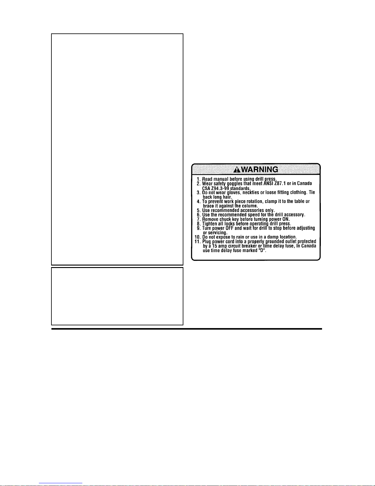
• Find and read all the warning labels
found on the drill press (shown
below).
WARNING: To reduce the risk of
mistakes that could cause serious, permanen t inju r y, do not
plug the drill press in until the
following steps have been satisfactorily completed.
When Installing Or Moving The Drill Press
Reduce the Risk of Dangerous
Environment.
• Use the drill press in a dry, indoor
place protected from rain.
• Keep work area well lighted.
• Use recom me nded accessori es.
The use of improper accessories
may cause risk of injury to persons.
To reduce the risk of injury from
unexpected drill press movement.
If there is any tendency of the drill
press to tilt or move during any use,
bolt it to the floor. Make sure and
leave adequate room to fully open the
belt guard. If the workpiece is too
large to easily support with one hand,
provide an auxiliary support .
• To reduce the risk of injury from
electrical shock, make sure your fingers do not touch the plug’s metal
prongs when plugging in or unplugging the drill press.
3

Safety Instructions For Drill Press (continued)
• Ne ver Stand On Tool. Serious
injury could occur if the tool tips or
you accidentally hit the cutting tool.
Before Each Use
Inspect your drill press.
• To reduce the risk of injury from
accidental starting, turn the switch
off, unplug the drill press, and
remove the switch key before raising
the guard, changing the cutting tool,
changing the setup, or adjusting
anything. Make sure switch is in
OFF position before plugging in.
• Check for alignment of moving
parts, binding of moving parts,
breakage of parts, drill pr ess stabil ity, and any other conditions that
may affect the way the drill press
works.
Do not store anything above or near
the tool where anyone might stand
on the tool to reach them.
• If any part is missing, bent or broken
in any way, or any electrical part
does not work properly, turn the drill
press off and unplug the drill press.
• Replace damaged or missing parts
before using the drill press again.
• Remove adjusting keys and
wrenches. Form a habit of checking
for and removing keys and adjusting
wrenches from table top before turning drill press on.
• Make sure all clamps and locks are
tight and no parts have excessive
play.
Use Only Accessories Designed For This Drill Press To Reduce
The Risk of Serious Injury From Thrown Broken Parts Or Work
Pieces
• W hen cutting large diame ter holes:
- Clamp the workpiece firmly to the
table. Otherwise the cutting may
grab and spin it at high speed.
- Use only one piece, cup -type, hole
cutters.
- Do not use fly cutters or m ulti-part
hole cutters as they can come
apart or become unbalanced in
use.
- Keep speed below 1500 R.P.M.
• Drum sanders must never be oper-
ated on this drill press at a speed
greater than 1800 R.P.M.
• Do not insta ll or use a ny d r ill t ha t
exceeds 7” in length or extends 6”
below the chuck jaws. They can
suddenly bend outward or break.
rotary planers on this drill press.
Kickback
• Kickback is the grabbing of the
workpiece by the rotating tool. The
workpiece can be thrown at a very
high speed in the direction of rotation. This Can Cause Serious
Injury . To reduce the possibility of
injury from kickback:
- Clamp the workpiece firmly to the
table whenever possible.
- Buffing or sanding wheels or
drums should be co ntacted on the
side moving away from you, not the
side moving toward you.
- Use only recommended accessories and follow the instructions supplied with the accessory.
• Do not use wire wheels, router bits,
shaper cutters, circle (fly) cutter s or
4

This drill press has 12 speeds as
listed below:
250 RPM 990 RPM
340 RPM 1550 RPM
390 RPM 1620 RPM
510 RPM 1900 RPM
600 RPM 2620 RPM
650 RPM 3100 RPM
See inside of guard for specific placement of belt on pulleys.
• To reduce the risk of injury from
parts thrown by the spri ng, fo l lo w
instructions exactly as given and
shown in adjusting spring tension of
quill.
• To prevent the workpiece from being
torn from your hands, spinning of
the tool, shattering the tool or being
thrown, always properly support
your work so it won’t shift or bind on
the tool:
Think Safety
Safety is a combination of operator
common sense and alertness at all
times when the drill press is being
used.
WARNING: Do not allow familiarity ( gained f rom fre quent use of
your drill press) to become commonplace. Always remem b er
that a careless fraction of a second is sufficient to inflict severe
injury.
Plan Your Work
• Don’t force the tool. It will do the job
better and safer at the rate for which
it was designed.
• Use the right tool. Don’t force tool or
attachment to do a job it was not
designed to do.
• If any part of your drill press is missing, malfunctioning, has been dam aged or broken...such as the motor
switch, or other operating control, a
safety device or the power cord, turn
the drill press off and unplug it until
the particular part is properly
repaired or replaced.
• Never place your fingers in a position where they could contact the
drill or other cutting tool if the workpiece should unexpectedly shift or
your hand should slip.
- Always position backup material
(use beneath the workpiece) to
contact the left side of the column.
- Whenever possible, position the
workpiece to contact the left side of
the column - If it is t oo short or the
table is tilted, clamp solidly to the
table. Use table slots or clamping
ledge around the outside edge of
the table.
- When using a drill press vise,
always fasten it to a table.
- Never do any work “Freehand”
(hand holding workpiece rather
than supporting it on the table),
except when polishing.
- Securely lock head to column,
table support to column and table
to table support before operating
drill press.
- Never move the head or table while
the tool is running.
- Before starting the operation, jog
the motor switch to make sure the
drill or other cutting tool does not
wobble or cause vibration.
- If a workpiece overhangs the table
suc h th at it will fal l o r ti p if not he ld,
clamp it to the table or provide auxiliary support.
- Use fixtures for unusual operations
to adequately hold, guide and position workpiece.
5

Safety Instructions For Drill Press (continued)
- Use the spindle speed recommended for the specific operation
and workpiece material - check the
inside of the be lt guard for drilli ng
information; for accessories, refer
to the instructions provided with
the accessories.
• Ne ver climb on the drill press table,
it could break or pull the entire drill
press down on you.
• Turn the motor switch off and put
away the switch key when leaving
the drill press.
• To reduce the risk of injury from
thrown work or tool contact, do not
perform layout, assembly or setup
work on the table while the cutting
tool is rotating.
• Don’t overreach. Keep proper footing and balance at all times.
• Maintain tools with care. Keep tools
sharp and clean for best and safest
performance. Foll ow instr uction s fo r
lubricating and changing accessories.
Plan Ahead To Protect Your Eyes, Hands, Face and Ears
Dress for safety
• Do not wear loose clothing, gloves,
neckties or jewelry (rings, wrist
watches). They can get caught and
draw you into moving parts.
• Wear nonslip footwear.
• Tie back long hair.
• For dusty operations, wear a dust
mask along with safety goggles.
Reduce the Risk of Accidental
Starting.
• Make sure switch is “OFF” before
plugging drill press into a power outlet.
• Ro ll long sleeves above the elbow.
• Noise levels vary widely . To reduce
the risk of possible hearing damage,
wear ear plugs or muffs when using
drill press for hours at a time.
• Any power tool can throw foreign
objects into the eyes. This can result
in permanent eye damage. Always
wear safety goggles, not glasses
comply ing with AN S I Z87.1 (or in
Canada CSA Z94.3-99) shown on
package. Everyday eyeglasses have
only impact resistant lenses. They
are not safety glasses. Safety goggles are available at many local
retail stores. Glasses or goggles not
in compliance with ANSI or CSA
could seriously hurt you when they
break.
WARNI NG: Don’t all ow familiarity
(gained from frequent use of
your drill press) to cause a careless mistake. Always remember
that a careless fraction of a second is enough to cause a severe
injury .
Keep Children Away
• Keep all visitors a safe distance
from the drill press.
• Make sure bystanders are clear of
the drill press and workpiece.
Before Leaving The Drill Press
• Turn the drill press off.
• Wait for tool bit to stop spinning.
• Unplug the drill pres s .
• Make workshop child-proof. Lock
the shop. Disconnect master
switches. Remo ve the yellow swi tch
key. Store it away from children and
others not qualified to use the tool.
6

Glossary of Terms
Workpiece
The item on which the cutting operation is
being performed.
Drill Bit or Drill
The cutting tool used in the dr ill press to
make holes in a workpiece.
Backup Material
A piece of wood placed between the
workpiece and table...it prevents wood in
the workpiece from splintering when the
drill passes through the backside of the
workpice...also prevents drilling into the
table top.
Revolutions Per Minute (R.P.M.)
The number of turns completed by a spinning object in one minute.
Spindle Speed
The R.P.M. of the spi ndle.
Backlash
The amount of handle movement or play
bet w ee n adja c ent moving pa rts.
Motor Specifications and Electrical Requirements
Power Supply and Motor Specifications
WARNING: To reduce the risk of
electrical hazards, fire hazards or
damage to the tool, use proper
circuit protection. Your tool is
wired at the factory for operation
using the voltage shown. Connect tool to a power line with the
appropriate voltage and a 15-amp
branch circuit. Use a 15-amp time
delay type fuse or circuit breaker.
To reduce the risk of shock or
fire, if power cor d is wo rn or cut,
or damaged in any way, have it
replaced immediately .
The A-C motor used on this tool is a
totally enclosed fan cooled (TEFC) , induction nonreversible type, having the following specification s :
Rated H.P 1/2
Voltage 110-120
Amperes 8.0
Hertz (Cycles ) 60
Phase Single
RPM 1700
Rotation of Shaf t Clockwise
General Electrical Connections
DANGER: To reduce the risk of
electrocution:
1. Use only identical replacement
parts when servicing. Servicing should be performed by a
qualified service technician.
2. Do not use in rain or where
floor is w et.
This tool is intended for indoor
residential use only.
WARNING: Do not permit fingers
to touch the terminals of plug
when installing or removing the
plug to or from the outlet.
7
Motor Specifications and Electrical Requirements
(continued)
110-120 Volt, 60 Hz. T ool
Information
NOTE: The plug supplied on your tool
may not fit into the outlet you are planning
to use. Your local electrical code may
require slightly different power cord plug
connections. If these differences exist
refer to and make the proper adjustments
per your local code before your tool is
plugged in and turned on.
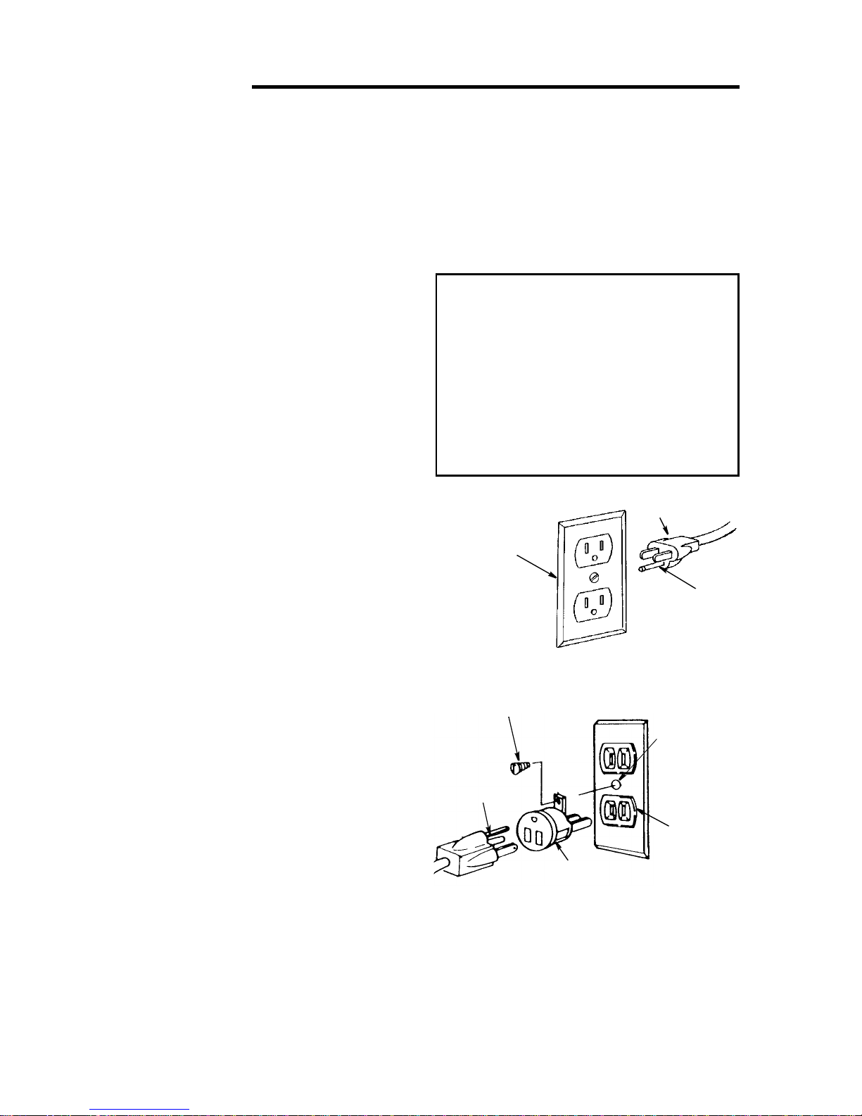
In the event of a malfunction or breakdown, grounding provides a path of least
resistance for electric current to reduce
the risk of electric shock. This tool is
equipped with an electric cord having an
equipment grounding conductor and a
grounding plug, as shown. The plug must
be plugged into a matching outlet that is
properly installed and grounded in accordance with all local codes and ordinances.
Do not modify the plug provided. If it will
not fit the outlet, have the proper outlet
installed by a qual ified electrician.
A temporary adapter may be used to connect this plug to a 2-prong outlet, as
shown, if a properly grounded thr ee prong
outlet is not available. This temporary
adapter should be used only until a properly grounded three prong outlet can be
installed by a qualified electrician. The
green colored rigid ear, lug and the like,
extending from the adapter must be connected to a permanent ground such as a
properly grounded outlet box.
NOTE: In Canada the use of a temporary
adapter is not permitted by the Canadian
electrical code.
Improper connection of the equipment
grounding conductor can resul t i n a risk of
electric shock. The conductor with insulation having an outer surface that is green
with or without yellow stripes is the equipment grounding conductor. If repair or
replacement of the electric cord or plug is
necessary, do not connect the equipmentgrounding conductor to a live terminal.
If the grounding instructions are not completely understood, or if you are in doubt
as to whether the tool is properly
grounded check with a qualified electrician or ser vice personnel.
WARNING: If not properly
grounded, this tool can cause an
electrical shock, particularly
when used in damp locations, in
proximit y to plu m bi ng, or out of
doors. If an electrical shock
occurs there is the potential of a
secondary hazard, suc h as your
hands to hit the cutting tool.
Properly
Grounded
3-Prong Outlet
Grounding Lug
3-Prong
Plug
Adapter
NOTE: The adapter illustrated is for use
only if you already have a properly
grounded 2-prong outlet.
NOTE: In Canada the use of a temporary
adapter is not permitted by the Canadian
Electrical Code.
3-Prong Plug
Grounding
Prong
Make sure this
Is Connected
to a Known
Ground
2-Prong
Outlet
8

Motor Safety Protection
IMPORTANT: To avoid motor damage,
this motor should be blown out or vacuumed frequently to keep sawdust from
interfering wit h normal motor ventila ti on.
1. Connect this tool to a power source
with the appropriate voltage for your
model and a 15-amp branch circuit
with a 15-amp time delay fu se or circuit
breaker. Usin g the wrong size fuse can
damage the motor.
2. If the motor won’t start, turn the switch
off immediately and unplug the tool.
Check the quill to make sure it turns
freely. If the quill is free, try to start the
motor again. If the motor still does not
start, refer to the "Motor Troubleshooting
Chart."
3. Fuses may "blow" or circuit breakers
may trip frequently if:
a.Motor Is Overloaded-Overloading
can occur if you feed too rapidly or
make too many start/stops in a short
time.
b. Line voltages shoul d not be more than
10% above or below the nameplate
voltage. For heavy loads, however, the
voltage at motor t erminals must e qual
the voltage specified for your model.
c. Improper or dull drill bit is used.
4. Most motor troubles may be traced to
loose or incorrect connections, overload,
low voltage (such as small size wire in
the su pply circ uit) or to o verly l ong supply circuit wire. Always check the connectio ns, the loa d and the supply cir cuit
whenever motor doesn’t work well.
Check wire sizes and length with the
Wire Size Chart shown.
Wire Sizes
NOTE: Make sure the proper extension
cord is used and is in good condition.
The use of any extension cord will cause
some loss of power. To keep t his to a minimum and to prevent overheating and
motor burnout, use the table at right to
determine the minimum wire size
(A.W.G.) extension cord.
Use only 3-wire extension cords which
have 3-prong gr ounding type plugs and 3-
pole receptacles which accept the tools
plug.
Extension Cord
Length
0-25
25-50
Gauge
(A.W.G.)
16
14
9

Unpacking and Checking Contents
Combinati
Tools Needed
Draw Light
Medium Screwdriver
Adjustable Wr ench
Phil lip s S cr e wd river
Combination Square
Framing
Square
Line on Board
Along this Edge
Should be no Gap or Overlap when Square
is Flipped Over in D o tted Position
on Square Must be True
Straight Edge of
Board 3/4" Thick
This Edge Must be
Perfectly Straight
Unpacking
WARNING: For your own safety,
never connect plug to power
source outlet until all assembly
steps are complete, and you
have read and understoo d the
safety and operating instructions.
The Drill Press is shipped compl ete in one
box.
1. Sepa r ate al l “loose parts” from packing
materials and check each item with
illustration and “Table of Loose Parts.”
WARNING: To reduce the risk of
injury, if any parts are missing,
do not attempt to assemble the
drill press, plug in the power
cord, or turn the switch on until
the missing parts are obtained
and installed correctly.
2.Rem ove the pr otec tive oi l that is app lied
to the table and column. Use any ordinary household type grease and spot
remover.
WARNING: To reduce the risk of
fire or toxic reaction, never use
gasoline, naptha or similar
highly volatile solvents to
remove protective oil.
3. Apply a coat of paste wax to the table
and column to prevent rust. Wipe all
parts tho roughl y with a clean dry cloth.
NOTE: Make certain all items are
accounted for before discarding any packing material.
10
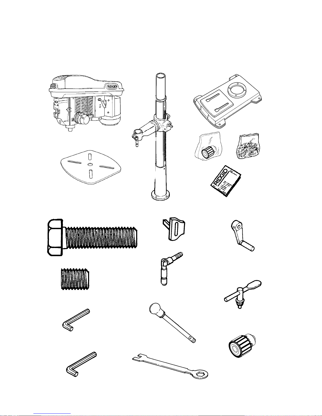
List of Lo ose P art s
Item Description Qty.
A Head A s m. ..... ..................................1
B Table.................................................1
C Column Support Ass em bly...............1
D Base .................................................1
A
C
E Bag Chuck .......................................1
F Bag of Loose Parts ..(Quantity vari es)
G Owne r s M a n ual................................ 1
D
B
Loose Part s
M10 x 1.5-40 Long
Hex Head Bolt (4)
E
Key Switch (1)
F
G
Crank
(With Set Screw) (1)
M10 x 1.5-12 Long
Hex Socket Set Screw (2)
M3 Hex “L” Wrench (1)
M5 Hex “L” Wrench (1)
Support Lock
Handle (1)
Chuck Key (1)
Feed Handle (3)
Chuck (1)
M24 Hex Box Wrench (1)
11
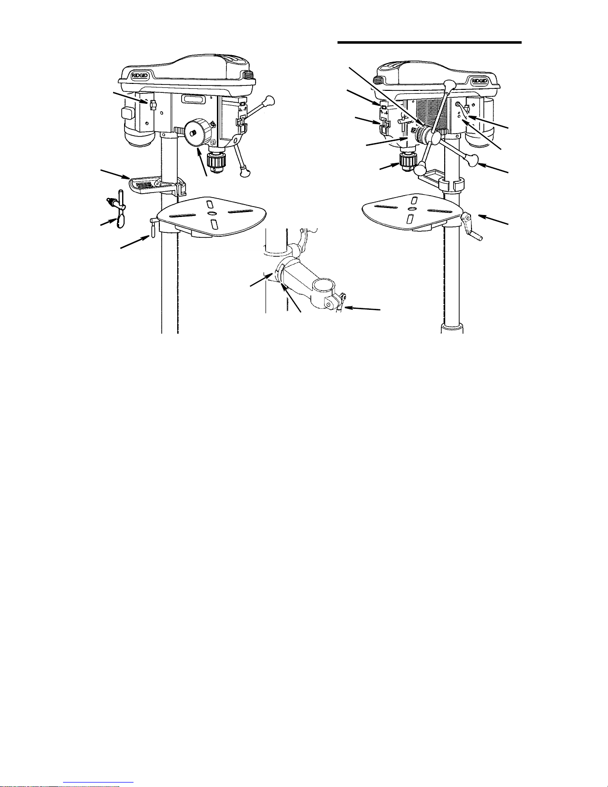
Location and Function of Controls
9
17
16
10
15
14
13
1. Belt Tension Handle...Turn handle
counterclockwise to apply tension to
belt, turn handle clockwise to release
belt tension.
2. Head Lock Set Screws...Locks the
head to the column. Always have
them locked in place while operating
the drill press.
3. Feed Handle...For moving the chuck
up or down. One or two of the handles may be removed if necessary
whenever the workpiece is of such
unusual shape that it interferes with
the handles.
4. Table Crank...Turn clockwise to ele-
vate table. Support lock must be
released before operating crank.
5. Chuck...Holds drill bit or other rec-
ommended accessory to perform
desired oper ati ons.
6. Depth Scale...Allows operator to
adjust drill press to drill to a desired
depth.
7. Drill “On-Off” Switch...Has locking
feature to prevent unauthorized and
possible hazardous use by children
and others.
8. Li ght “On-Off” Switch...Turns the
light on and off .
8
7
6
5
11
12
9. Depth Scale Lock...Locks the depth
scale at selected depth.
10. Spring Cap...Provides means to
adjust q uill s pr in g te nsio n .
11. Table Lock...Allows table to be
rotated in various positions and
locked.
12. T ab le Bevel Lock ...L ocks the table in
any position from 0°- 45°.
13. Bevel Scale...Shows degree table is
tilted for bevel operations. Scale is
mounted on side of arm.
14. Support Lock Handle...Tightening
locks tab le support to colum n. Always
have it locked in place while operating the drill press.
15. Chuck Key...Used to tighten drill in
the chuck and also to loosen the
chuck for drill removal.
16. Storage Tray...Conveniently holds
drill bits and other accessories.
17. Belt Tension Lock Handles...Tight-
ening handles locks motor bracket
support to maintain correct belt distance and tension.
Note and follow the saf ety warnings
and instructions that appear on the
panel on the right side of the head.
1
2
3
4
12
Assembly
WARNING: To reduce the risk of
injury from unexpected starting
or electrical shock, never connect plug to outlet until all
assembly steps are completed
and you rea d and unders ta nd al l
instructions.
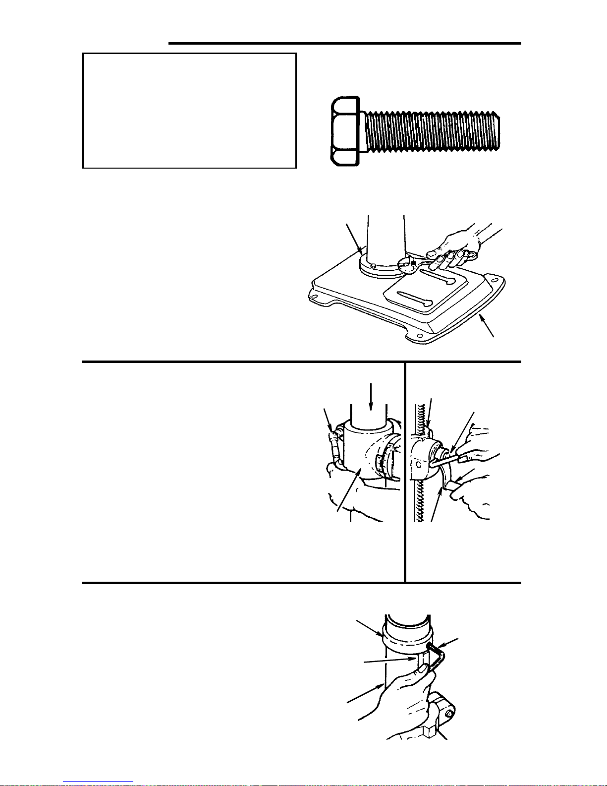
Assembly of Base/Column
10mm Dia. x 40mm
Hex Head Bolt (4)
1. Locate four ( 4) 10mm dia. x 40mm long
bolts among loose parts bag.
2. Po sition base on floor. Remove protec-
tiv e covering and discard.
3. Remove protective sleeve from column
tube and d iscard. Place co lumn ass embly on base, and align holes in column
support with holes in base.
4. Install a bolt in each hole through col-
umn sup port and base and t ighten with
adjustable wrench.
5. Locate table crank and support lock from
loose parts.
6.Install support lock from left side into
tabl e support and tighten by hand.
7. Ins tall ta ble cran k assem bly and ti ghten
set screw with a 3mm hex “L” wrench.
Do not o ver tighten. S et screw sh ould be
tighten ed against the flat section o f the
shaft.
Column
Support
Support
Lock
Column
Table
Support
Base
Elevation
Worm
Shaft
Handle
NOTE: To minimize crank backlash,
tighten support lock, rotate elevation
worm shaft clockwise, then assemble
crank tight against table support and
tighten set screw.
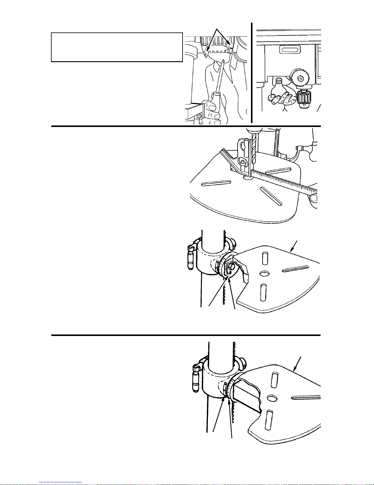
8. Check column collar for proper adjust-
ment. Collar should not be angled on the
column and it should be positioned so
rack will slide freely in collar when table
is rotated 360° around column tube. If
readjusted, only tighten set screw
enough to keep collar in place.
NOTE: To reduce the risk of column or
collar damage, do not overtighten set
screw.
Table
Support
Column
Collar
Column
13
Table
Crank
Do Not
Overtighten
Set Screw
Rack
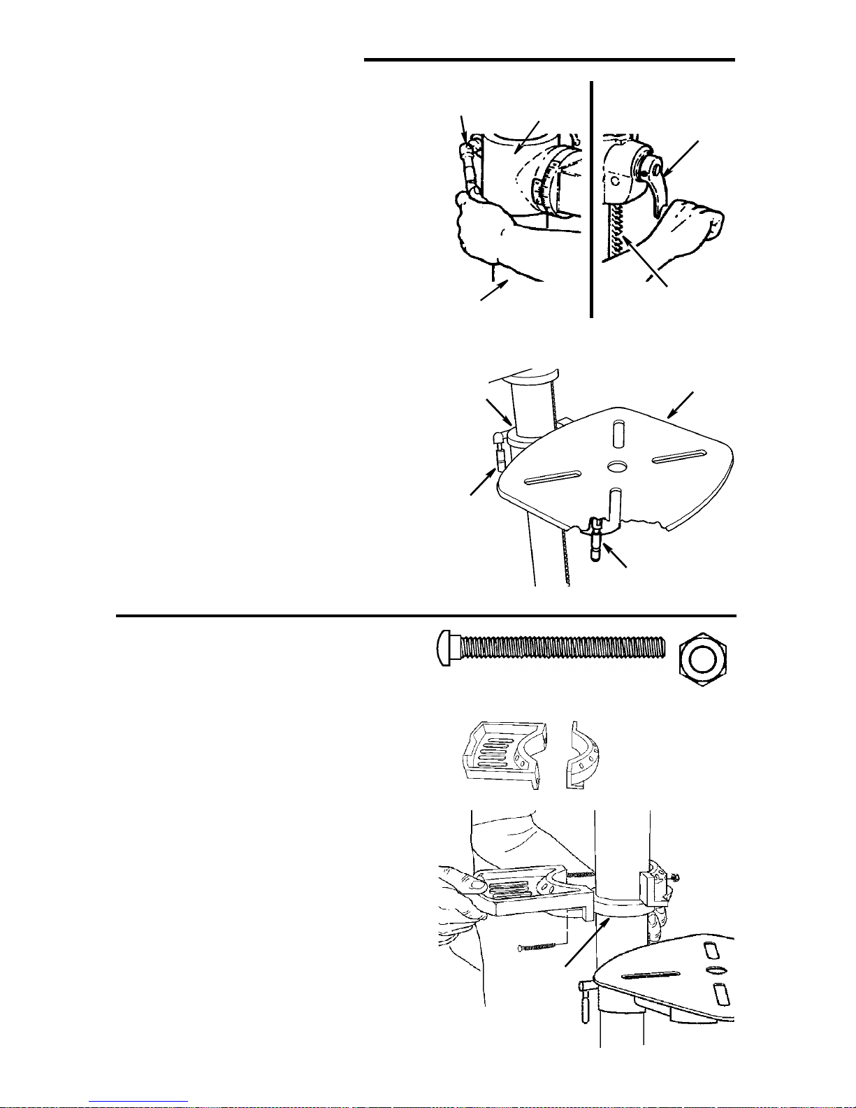
Assembly (continued)
Installing The Table
1. Loosen support lock and raise table
support by turning table crank clockwise until support is at a working
height level. Tighten support lock.
2. Remove protective covering from table
and discard. Loosen table lock, place
table in table support and tighten table
lock (located under table) by hand.
NOTE: If table won’t fit into table support
easily, pry open table support with a flat
blade screwdr iver.
Support
Lock
Column
Table
Support
Support
Lock
Table
Support
Table
Crank
Rack
Table
Installing the Storage Tray
1. Locate the two piece storage tray, (2)
two 5mm dia. x 60 mm long screw, and
(2) two 5 mm hex nuts.
2. Attach to the column as shown. Make
sure the storage tray is located above
the column collar. Be careful not to overtighten the nuts.
Pan Head Screw
5mm x 60mm
(Not Ac tu a l S iz e )
Storage Tray
Table
Lock
Hex Nut
5 mm
Column
Collar
14
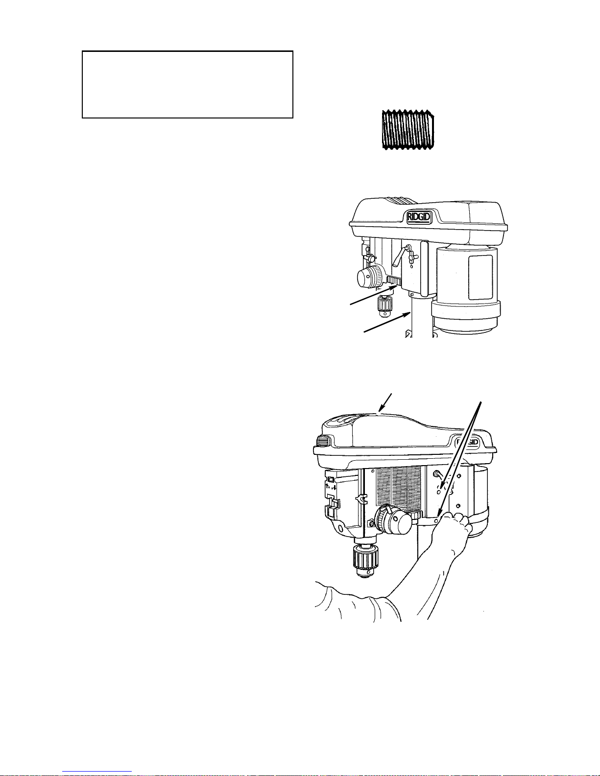
Installing the Head
CAUTION: The head assembly
weighs about 80 pounds. To
reduce the risk of back injury get
help to lift the head.
1. Locate (2) two 10mm dia. x 12mm long
set screws in loose parts bag.
2.Remove protective bag from head
assembly and discard. Carefully lift head
above col um n tube an d slide it onto co lumn making sure head slides down over
column as far as possible. Align head
with table and base.
10mm Dia. x 12mm
Set Screw
Head
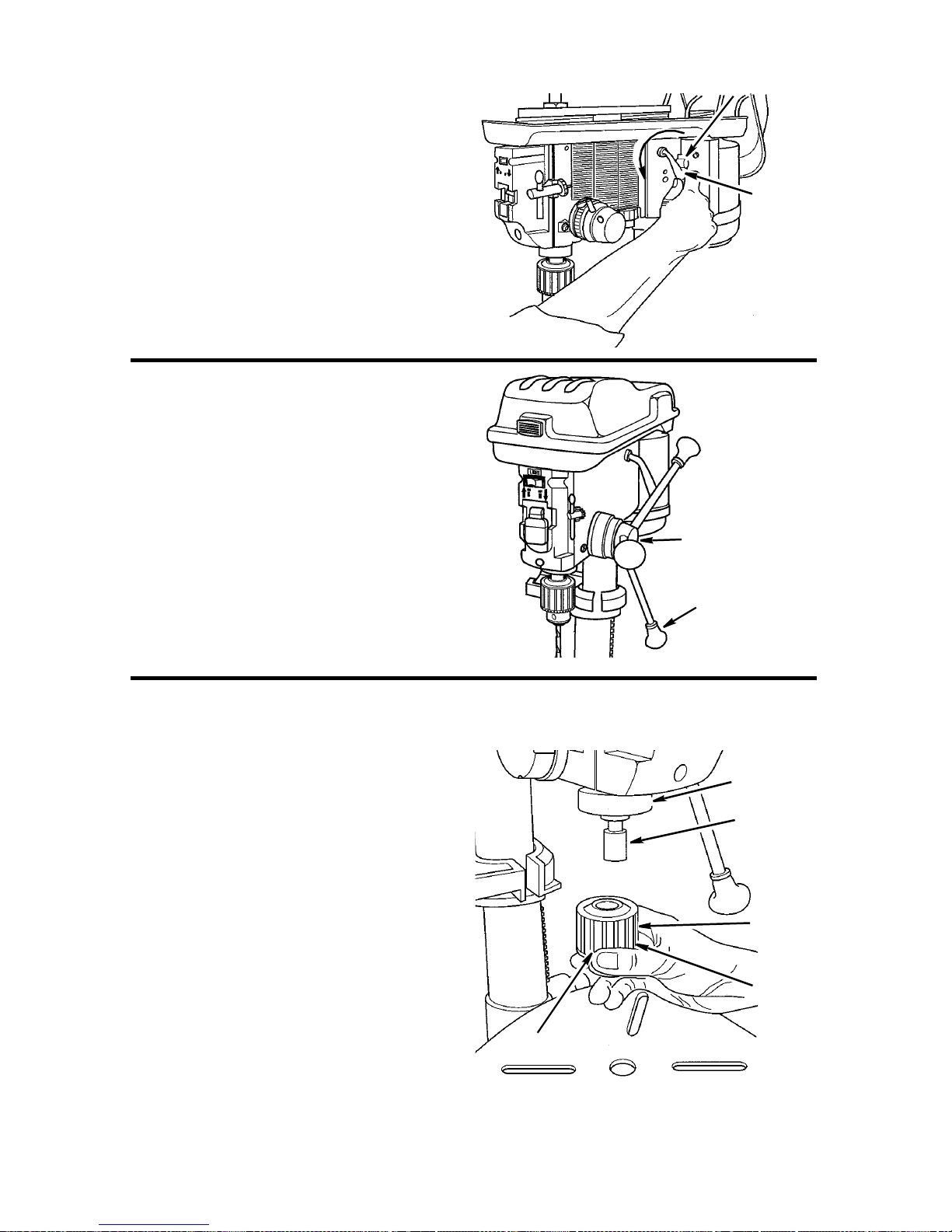
3.Install a set screw in each hole (as indi-
cated) on t he r ig ht s i de of th e head, and
using a 5mm hex “L” wrench, tighten the
two head lock set screws.
Column
Head
Head Lock
Set Screws
15
Assembly (continued)
Pulley Alignment and Speed
Adjustment
Checking Pulley(s) Alignment
WARNING: To reduce the risk of
injury due to accidental starting
always turn drill press off and
remove switch key before making belt adjustments.
Pulley alignment is set at the factory and
should not require further adjustment. If
the pulleys or motor are removed for service, follow the pulley alignment instructions below.
1. Place the idler pulley from loose parts
bag into the head as shown. Place
belts from loose parts bag on pulleys
following speed adjustment instructions below.
2.Place a straightedge such as a piece of
wood, metal, or framing square across
the top of pulle ys.
3. Th e top of all three pul leys sho uld touch
the straightedge.
Straightedge
Lower
Belt
Guard
4.If not:
• Loosen the motor mount nuts.
• Move the motor until the pulleys are
in line.
• Retighten the motor mount nuts.
NOTE: To avoid rattles or other noise,
motor frame must not touch lower belt
guard.
Belt
Tension
Lock
Handle
Motor
Mount
Nuts
Motor
Speed Adjustment
1. Release belt tension lock handles
located on each side of drill press head
by turning them counterclockwise.
2. Lo osen bel t tension b y turning belt ten-
sion handle clockwise.
3. Use speed chart inside belt guard to
choose speed for drilling operation.
Install belts in correct position for desired
speed. The longer of the two belts is
always position ed between the spin dle pulley and idler pulley.
IMPORTANT: Visu ally check t o m a ke sure
the fo ur r ibs on th e be l t are place d i nto t he
four pulley grooves.
Spindle
Pulley
Belt
Tension
Handle
Idler
Pulley
Properly aligned bel t shoul d not
touch the stepped surface on
the pulley
16
Tensioning Belt
1. Apply tension to belt by turning belt
tension handle counterclockwise until
belt deflects approximately 1/2 inch by
thumb pressure at its center.
2.T ighte n belt tension loc k handles.
NOTE: Over tensioning belt may cause
motor not to start or damage bearings.
3. If belt slips while drilling, readjust belt
tension. Also make sure the ribs in the
belt are aligned with groo ves in th e pulley.
Installing Feed Handles
1. Locate three (3) feed handles among
loose parts.
2.Screw the feed handles into the
threaded holes in the hub and tighten.
3. Tighten feed handles using the open
end of the M24 hex box wrench included
with drill press.
Belt Tension
Lock Handle
Belt
Tension
Handle
Tighten Using
M24 Wrench
Hub
Installing the Drill Chuck
1. Clean the tapered surfaces on the
chuck and spindle with a clean cloth.
Make sure there are no foreign particles sticking to these surfaces. The
slightest pi ece of dirt on these sur faces
will prevent the arbor from seating
properly. This will cause the drill to
“wobble”.
2.Slide chuck into spindle of drill press.
3. Push up on chuck assembly as you
rotate it.
Feed
Handle
Quill
Spindle
Tapered
Surface
Arbor
Tapered
Surface
Chuck
Sleeve
Chuck Body
17
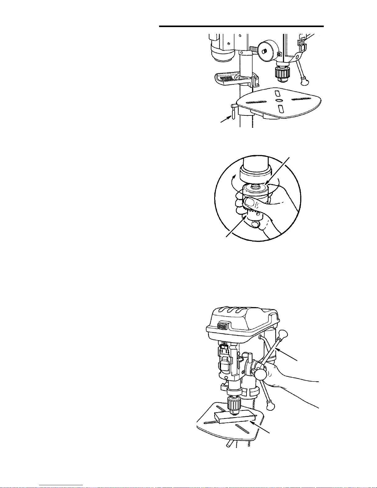
Assembly (continued)
4. Unlock support lock and raise table so
its about two (2) inches below tip of
chuck.
5. Turn chuck sleeve clockwise and open
jaws in chuck completely.
Support
Lock
Chuck
Sleeve
6.Place a piece of wood on table. Turn
feed handles counterclockwise and force
chuck against table until chuck is secure.
Chuck
Feed
Handle
Wood
18
Installing Light Bulb
WARNING: To reduce the risk of
electrical shock, unplug the tool
before install ing l ight bulb.
1. Remove the amber colored lens cover
by r e m o ving th e two Phi llips sc r ews.
2. Install a light bulb (not larger than 60
watt) into the socket inside the head.
3. Replace the lens cover.
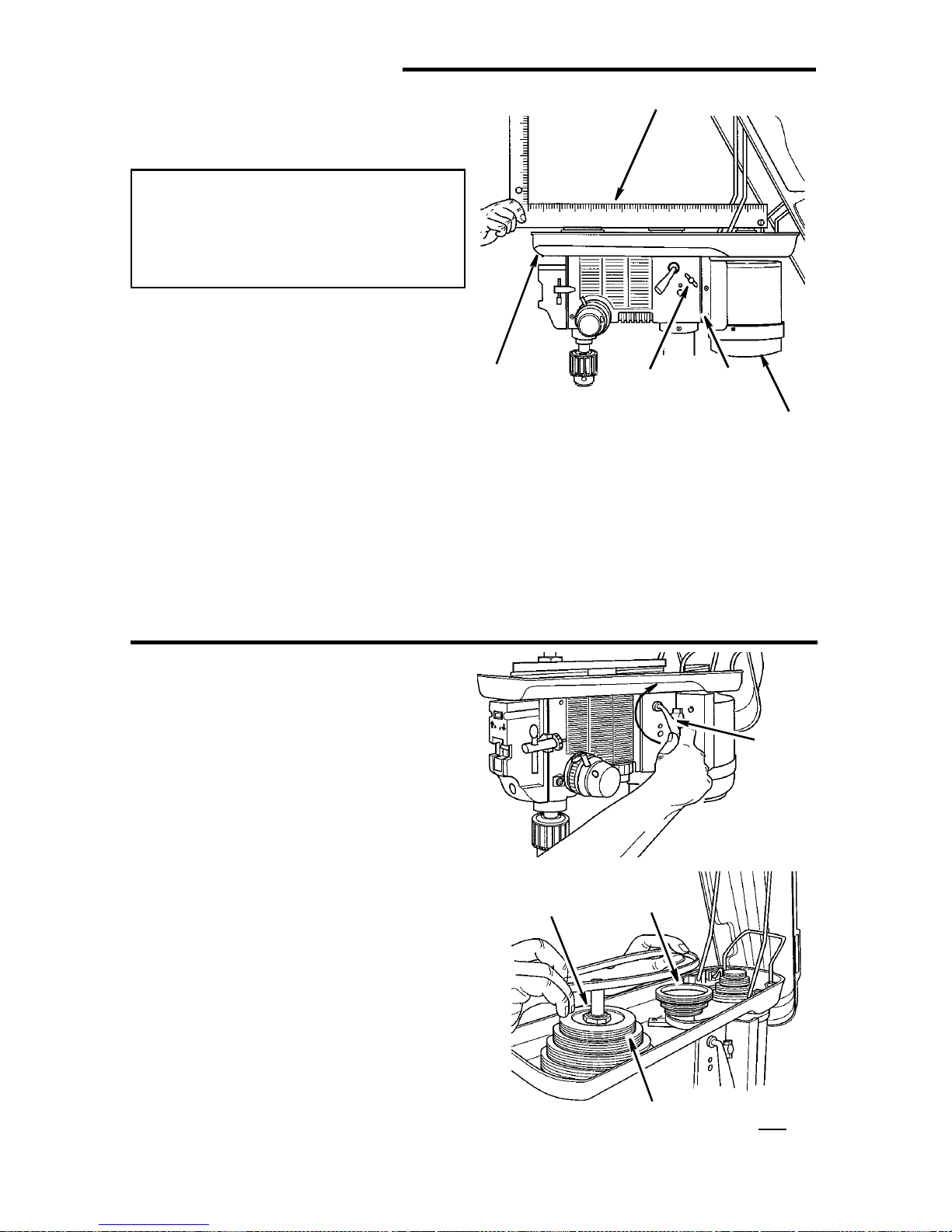
Adjusting the Table Sq uare To
Head
NOTE: The combination square must be
“true”. See “Unpacking and Checking
Contents” section for method.
1. Insert precision round steel rod or
straight drill bit approximately 3” long
into chuck and tighten.
Remove Screws
2. W ith table raised to working h eight and
locked on column, place combination
square flat on table beside rod or bit.
3.If an ad jus tm ent i s nec e ss ary, loo se n th e
set screw under bevel lock with 3mm “L”
wrenc h, t h en l o osen the ta bl e b evel lock
bolt with the 24mm hex box wrench
(included). (This adjustment is located
under the table).
4.Align the table squ are to the rotor bit b y
rotati ng table until the squar e and rod o r
bit are in line.
5.Retighten table bevel lock.
6.Retighte n set screw.
Bevel Scale
NOTE: The bevel scale has been
included to provide a quick method for
beveling the table to approximate angles.
If precise accuracy is necessary, a
square, or other precision measuring tool
should be used to position the table.
1. To use the bevel scale do the f ollowing.
a.Loosen set screw and table bevel
lock (see step 3 above).
b. M ove table so desired angle on bevel
scale is straight across from zero line
on pointer.
c. Retighten table bevel lock and set screw.
Set
Screw
Pointer
Table
Table Bevel
Lock
Table
Scale
19
Assembly (continued)
Converting From Right Hand
Operation to Left Hand Operation
The drill press is shipped from the factory
with feed handles set-up for right hand
operation. However, if desired, the drill
press feed handles can be converted to
left hand operation.
WARNING: For your own safety
turn switch “OF F” and remove
plug from po we r source outl et
before making any adjustments.
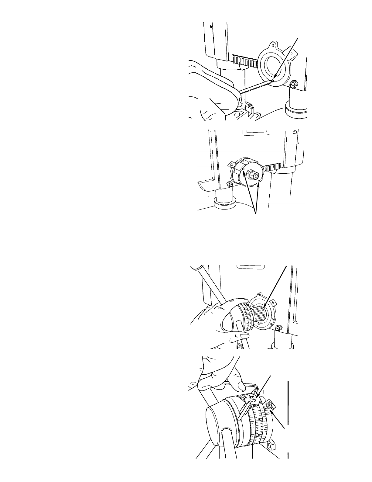
1.To help keep the drill chuck from falling
on to the floor, place a piece of scrap
wood on top of the t able and r aise the
tabl e until it engages the ch uck.
CAUTION: Releasing the spring
assembly without proper support
of the chuck will allow the quill
assembly to drop on top of the
drill press table.
4mm Cap
Screw
M12
Nuts
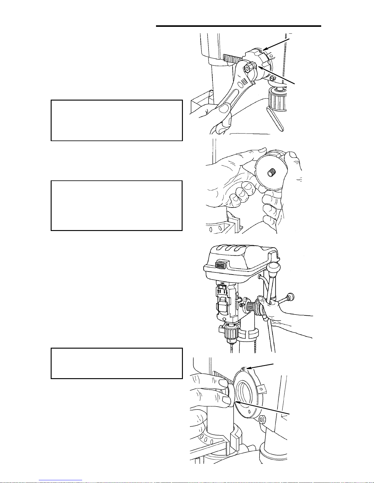
2.Firmly hold spring housing against head
so it remains engaged with the 4mm
cap screw. Remove both M12 nuts and
M12 washer from the feed handle
assembly shaft.
3.Use both hands to firmly grasp the
spring assembly. Pull the spring
assembly slightly away from the drill
press, disengaging the spring housing
from the cap screw. While firmly holding the housing, allow the spring
assembly to unwind clockwise until
the spring tensi on is relieved.
CAUTION: To prevent injury, be
careful not to allow the spring
assem bl y t o rapi dl y un wi nd.
4.Remove the spring as sem bly.
5.Slide the feed handle assembly out
from the right si de of t he head.
6.Remove the bushing located on the
left of the head assembly as shown. It
may be necessary to tap this bushing
out from the right side. Reinstall this
bushing on the right side of the drill
press.
Remove 4mm
Cap Screws
Remove
Bushing
20
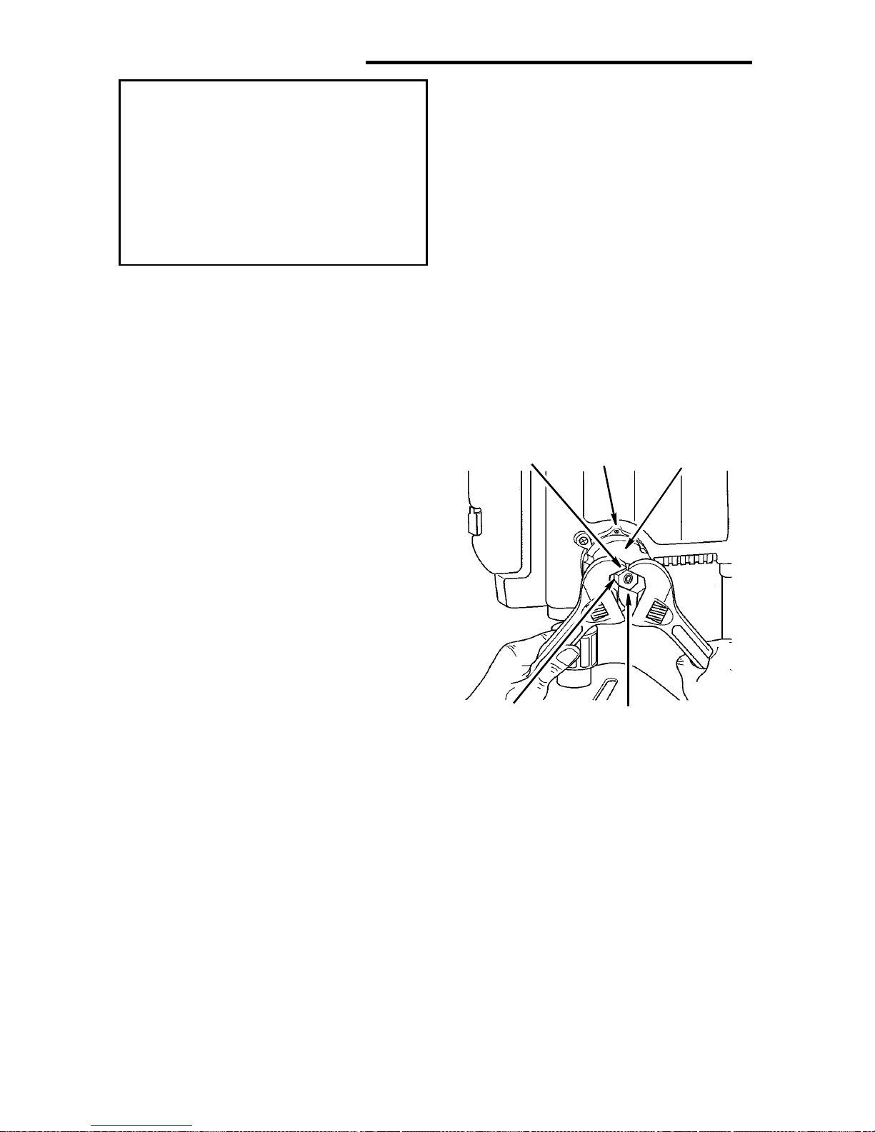
7.Remove the 4mm socket head cap
screw from the left side of the drill
press and install in the same position
on the right side of the drill press.
Tighten screw .
8.Remove the 6mm stop pin screw from
the right side of the drill press and
inst all in th e left side of the dri ll press
as shown. Ti ghten stop pin screw.
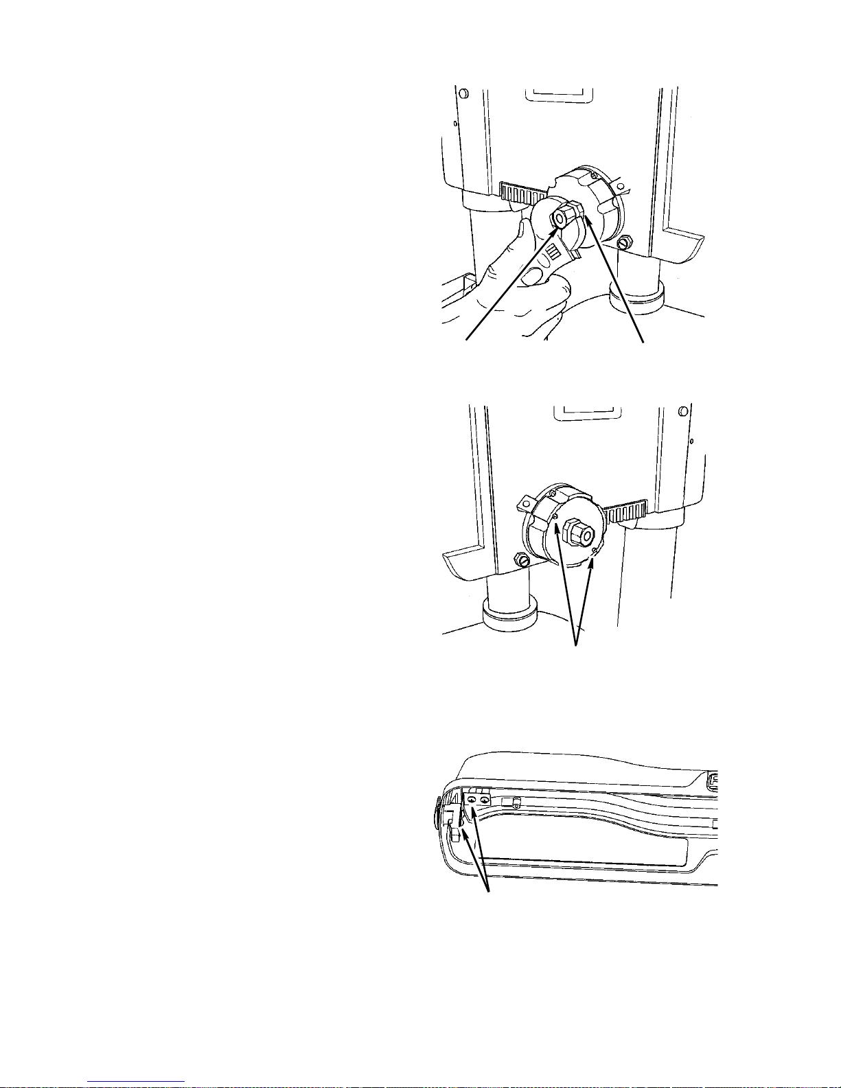
9. Install the feed handle assembly and
depth stop ring on the left side of the
drill p ress. With the chuck at its highest possible position, turn the depth
scale clockwise until it stops and
tighten the depth scale lock. This will
prevent the quill from dropping while
installing the spring.
10.Install the spr ing assembl y on the righ t
side of the drill press, making sure the
two housing screw heads face outwards. The center tab of the spring
must go in the slot on the feed handle
assembly.
If necessary, use a screwdriver to align
and keep spring centered during installation.
11. Replace M12 washer and screw the
outer and inner nuts back on the feed
handle assembly. Hold the spring
assembly in place and loosely assemble both nuts. See following page for
quill retur n spring adjustment.
12. Remove the depth scale and reposition so numbers are legi ble as shown.
13.Remove the depth scale indicator
from the right side of the drill press
and reinstall on the left side of the drill
press.
14.Remove the scrap wood from the
table top.
Install 6mm
Stop Screw
Right side housing screws
fa ce ou twa rd as show n
Install Feed Handle
Assembly
Remove Depth Scale
and Reposition
Install Depth
Scale
Indicator
21
Assembly (continued)
WARNING: For your own safety
turn switch “OF F” and remove
plug from po we r source outl et
before making any adjustments.
To reduce the risk of injury from
thrown parts due to spring
release, follow instructions carefully and wear eye goggles.
Quill Return Spri ng
NOTE: The return spring tension is set at
the factory and should not require further
adjustment.
If you switch ed your drill press from right
hand operation to left hand ope ration, follow the procedure below to adjust spring
tension.
1. With the chuck at its highest possible
position, turn the depth scale clockwise
until it stops and tighten the depth
scale lock. This will prevent the quill
from dropping while tensioning the
spring.
Notch
4 mm Cap
Screw
Spring
Cap
NOTE: For right hand operation (feed
handle on right side) turn the depth scale
counterclockwise until it stops and
tighten the depth scale lock.
2.Check to make sure spring housing is
mounted correctly. When spring housing is placed on the right side (feed
handles mounted on left side), the
housing screws face out as shown.
When spring housing is placed on the
left side (feed handles mounted on
right side), the housing screws face
toward the head as shown .
3.Lower table for additional clearance.
4.Firmly hold the spring assembly
against the head keeping it engaged
with the 4mm cap screw while loosening and removing the outer nut only.
5.Loosen inner nut (approximately 1/4
inch) and disengage spring housing
from the 4mm cap screw. Using both
hands turn spring clockwise to the
next notch and engage with the 4mm
cap screw.
Nut (Outer)Nut (I nne r)
22
NOTE: For right hand operation (feed
handle on right side) turn spring counterclockwise to the next notch and engage
with the 4mm cap screw.
6.Finger tighten inner nut against spring
housing. Do not overtighten as this will
restric t qu ill move ment.
7.Loosen depth scale lock and check
quill return by rotating feed handles,
lowering quil l.
8.Proper tension is achieved when quill
returns gently to full up position when
released from 3/4” depth.
9.If there is not enough tension on
spring, repeat steps 5-8 moving only
one notch each time and checking
tension after each repetition .
10.After adjusting spring, replace outer
nut and tighten to inner nut. But do not
overtighten against inner nut.
11.Check quill movement to make sure it
is smooth and unrestricted. If movement is too tight, loosen outer nut and
slightly loosen inner nut until unrestricted. Retighten outer nut.
Left side housing screws
face towards head as shown
Nut (Out e r )
Nut (Inner)
Adjusting Belt Lat c h G uard
The button latch is adjusted at the factory
to be self latching when the pulley guard
lid is closed. If adjustment is needed,
loosen the two screws securing the latch
to the lid and move latch back until the lid
closes without depressing the button. The
button can also be adjusted up and down
to assure lid closes tight by loosening the
two screws in back of the latch button,
and moving the button up or down as
needed.
Right side housing screws
face outward as shown
Latch Adjusting Screws
23
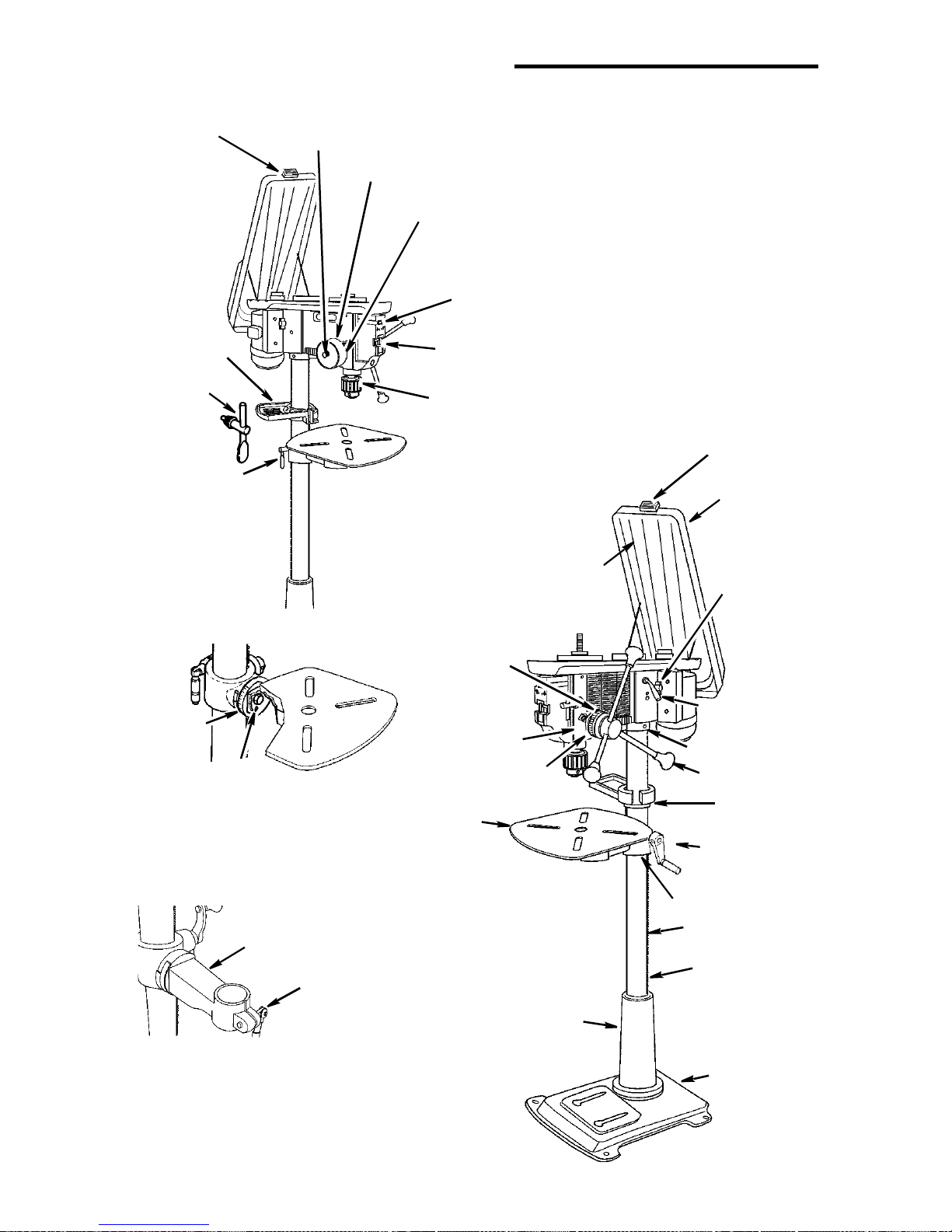
Getting To Know Your Drill Press
19 Belt Guard
Latch
27 Storage
Tray
26 Chuck
Key
25 Support
Lock
Feed Spring
Adjustment
Feed Spring
18 Spring
Cap
Light “On-O ff”
28 Drill “On-Off”
20 Chuc k
1 Drill Speed Table
(Inside B elt Gua r d)
Switch
Switch
19 Belt Guard Latch
2 Belt Guard
3 Belt Tension
Lock Handle
24 Bevel
Scale
22 Table Bevel
(Under Table)
Lock
21 Arm
23 Table
Lock
17
Depth Scale
Lock
16 Depth Scale
Indicator
14 Table
15 Depth
Scale
12 Column
Support
4 Belt Tension
Handle
5 Head Lock
6 Feed Handle
7 Column
Collar
9 Table Crank
8 Table Support
10 Rack
13 Column
11 Base
24
 Loading...