

RIDGID DP1500 Owner's Manual

2:1(5·60$18$/
$VVHPEO\
2SHUDWLRQ
5HSDLU3DUWV
)RU<RXU6DIHW\
5HDGDOOLQVWUXFWLRQVFDUHIXOO\
48(67,21625&200(176"
&$//5,'*,'
Part No. SP6158 Printed in U.S.A.
'3
,1&+)/22502'(/
'5,//35(66
2
Table of Contents
Section Page
Table of Contents .......................................................... 2
Safety Instructions For Drill Press .................................2
Safety Signal Words ...................................................2
Before Using The Drill Press .......................................2
When Installing Or Moving The Drill Press ................. 3
Before Each Use .........................................................3
Use Only Accessories Designed For This Drill Press
To Reduce The Risk of Serious Injury From Thrown
Broken Parts Or Work Pieces. ...................................3
Plan Ahead To Protect Your Eyes, Hands, Face
and Ears .................................................................... 4
Glossary of Terms .........................................................5
Motor Specifications and Electrical Requirements ........5
Power Supply and Motor Specifications ..................... 5
General Electrical Connections ................................... 5
110-120 Volt, 60 Hz. Tool Information ........................5
Motor Safety Protection ..............................................6
Wire Sizes ...................................................................6
Unpacking and Checking Contents ............................... 7
Tools Needed .................. ...... ....... ...... ....... ...... ....... ..... 7
Unpacking ....................... ............................................7
List of Loose Parts ...................................................... 7
Loose Parts in Box and Bag ....................................... 8
Location and Function of Controls .................................9
Assembly .............. .......................................................10
Assembly of Base/Column ........................................10
Installing The Table ............... ....... ...... ....... ...... ....... ... 11
Installing the Head .................................................... 11
Pulley Alignment and Speed Adsjustment ................12
Tensioning Belt .........................................................12
Installing Feed Handles ............... ...... ....... ...... ..........13
Section Page
Installing the Chuck .................................................. 13
Installing Light Bulb ................................................... 15
Adjusting the Table Square To Head ........................ 15
Bevel Scale ................................................................. 15
Getting To Know Your Drill Press ................................ 16
Drilling to a Specific Depth ........................................ 19
Another Way - Depth Scale ...................................... 19
Locking Chuck at Desired Depth .............................. 19
Removing Chuck and Arbor ...................................... 20
Re-installing the chuck and arbor ............................. 21
Safety Instructions for Basic Drill Press Operation ...... 22
Plan Ahead To Protect Your Eyes, Hands, Face
and Ears ................................................................. 22
Use Only Accessories Des ign ed Fo r This Dri ll Pres s
To Reduce the Risk of Serious Injury From Thrown
Broken Parts Or Work Pieces. ................................. 22
Basic Drill Press Operation ......................................... 23
Installing Drills ........................................................... 23
Positioning Table and Workpiece ............................. 23
Tilting Table .............................................................. 24
Hole Location ............................................................ 24
Feeding .................... .............................................. ...24
Adjustments ................ ............. ............. ....... ............. ... 24
Quill Return Spring ............... ....... ...... ....... ...... ....... ... 2 4
Maintenance ......... ....................................... ................ 25
Maintenance ............................................................. 25
Lubrication ................................................................ 25
Wiring Diagram ............................................................ 25
Troubleshooting ................. ............. ............. ...... .......... 26
Repair Parts ................................................................ 27
Safety Instructions For Drill Press
Safety is a combinati on of comm on sense, staying alert and k nowin g how your dr ill pre ss works. Read this m anual to
understand this drill press.
Safety Signal Words
DANGER: means if the safety information is not followed
someone will be seriously injured or killed.
WARNING: means if the safety information is not followed
someone could be seriously injured or killed.
CAUTION: means if the safety informat ion is not followed
someone may be injured.
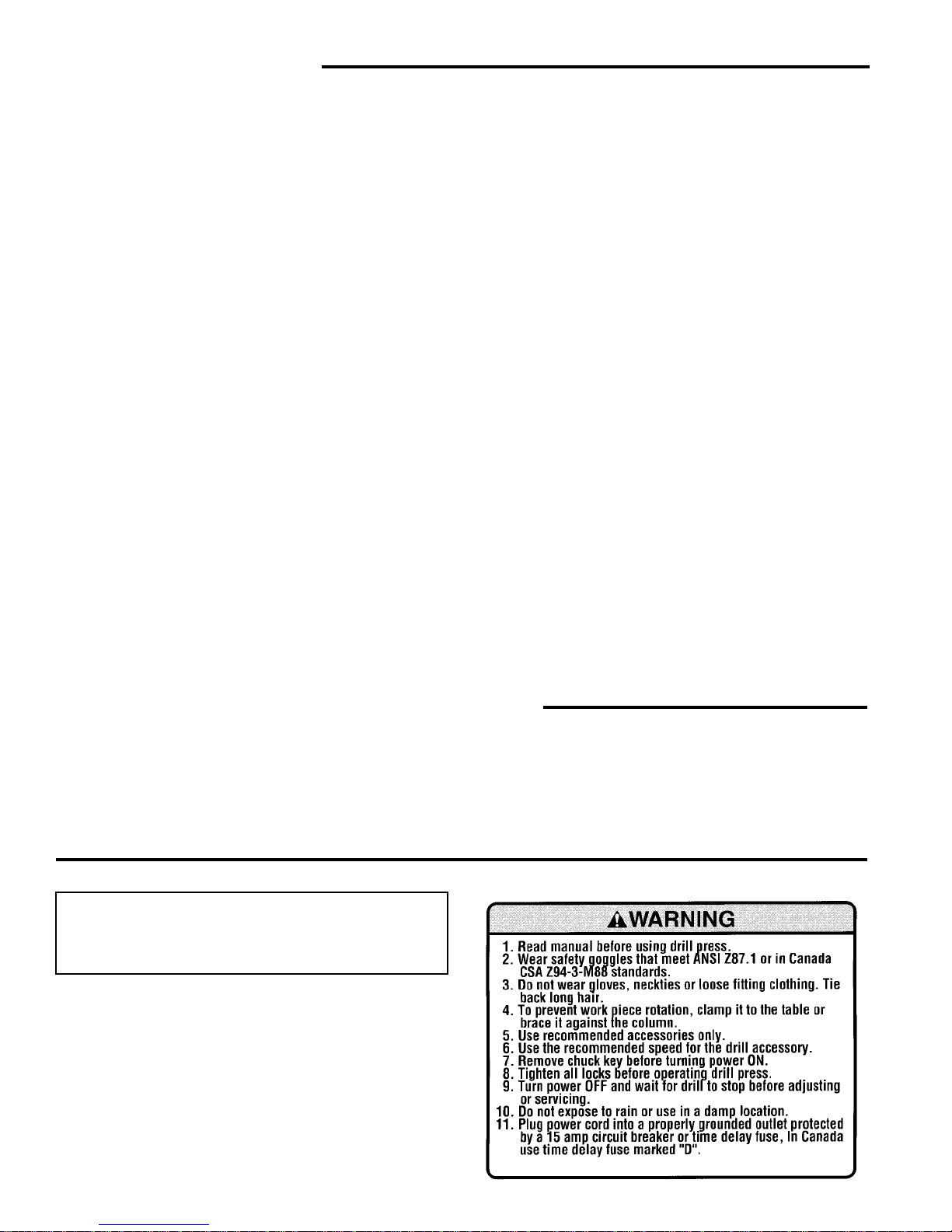
Before Using The Drill Press
WARNING: To reduce the risk of mistakes that
could cause serious, permanent injury, do not plug
the drill press in until the following steps have
been satisfactorily completed.
• Completely assemble and align drill press (See
“Assembly” section).
• Learn the use and function of the ON-OFF switch.
(See “Getting to Know Your Drill Press” section).
• Review and understand all safety instructions and
operating procedures in this manual.
• Review the maintenance methods for this drill press
(See “Maintenance” section).
• Find and read all the war ning labels found on the dr ill
press (shown at right).

3
When Installing Or Moving The Drill Press
Reduce the Risk of Dangerous Environment.
• Use the drill press in a dry, indoor place protected from
rain.
• Keep work area well lighted.
• Use recommended acce ssories. The use of improper
accessories may cause risk of injury to persons.
To reduce the risk of injury from unexpected drill
press movement.
If there is any tendency of the drill press to tilt or
move during any use, bolt it to the floor. If the workpiece is too large to easily support with one hand,
provide an auxiliary support.
• To reduce the r is k of inj ury from electr ic al shock, make
sure your fingers do not touch th e plug’s metal prongs
when plugging in or unplugging the drill press.
• Never Stand On Tool. Serious injury could occur if the
tool tips or you acciden tally hit the cutting to ol. Do not
store anything above or near the tool where anyone
might stand on the tool to reach them.
Before Each Use
Inspect your drill press.
• To reduce the risk of injury from accidental starting,
turn the switch off, unplug the dr ill press, and remove
the switch key before raising the guard, changing the
cutting tool, ch anging the setup, or adju sting anyth ing.
Make sure switch is in OFF position before plugging in.
• Check for alignment of moving parts, binding of moving
parts, breakage of parts, drill press stabi lity, and any
other conditions that may affect the way the drill press
works.
• If any part is missing, ben t or br oken in any wa y, or any
electrical part does not work properly, turn the drill
press off and unplug the drill press.
• Replace damaged or missing parts before using the
drill press again.
• Remove adjusting keys and wrenches. Form a hab it o f
checking for and removing keys and adjusting
wrenches from table top before turning drill press on.
• Make sure all clamps and locks are tight and n o par ts
have excessive play.
Use Only Accessories Designed For This Drill Press To Reduce The Risk of Serious Injury
From Thrown Broken Parts Or Work Pieces
• When cutting large diameter holes:
- Cla mp the workpiece firmly to th e table. Otherwise
the cutting may grab and spin it at high speed.
- Use only one piece, cup-type, hole cutters.
- Do not use fly cutters or multi-pa rt hole cutters as
they can come apart or become unbalanced in use.
- Keep speed below 1500 R.P.M.
• Drum sanders must never be operated on this drill
press at a speed greater than 1800 R.P.M.
• Do not install or use any drill tha t exceeds 7” in length
or extends 6” below the chuck jaws. They can suddenly bend outward or break.
• Do not use wire wheels, router bits, shaper cutters, circle (fly) cutters or rotary planers on this drill press.
Kickback
• Kickback is the grabbing of the workpiece by the rot ating tool. The workpiece can be thrown at very high
speed in the direction of rotation. This Can Cause
Serious Injury. To reduce the possibi lity o f inj ur y fr om
kickback:
• Clamp the workpiece fir mly to the table whenever possible.
• Buffing or sanding wheels or drums should be contacted on the side moving away from you, not the side
moving toward you.
• Use only recommended accessories and follow the
instructions supplied with the accessory.
This drill press has 12 speeds as listed below:
250 RPM 990 RPM
340 RPM 1550 RPM
390 RPM 1620 RPM
510 RPM 1900 RPM
600 RPM 2620 RPM
650 RPM 3100 RPM
See inside of guard for specific placement of belt on
pulleys.
Think Safety
Safety is a combination of operator commo n sense and
alertness at all times when the drill press is being used.
WARNING: Do not allow familiarity (gained from
frequent use of your drill press) to become commonplace. Always remember that a careless fraction of a second is sufficient to inflict severe injury.
Plan Your Work
• Don’t force the tool. It will do the job better and safer at
the rate for which it was designed.
• Use the right tool. Don’t force tool or attachment to do
a job it was not designed to do.
• If any part of your drill press is missing, malfunctioning,
has been damaged or broken...such as the motor
switch, or other operating control, a safety device or
the power cord, turn the drill press off and unplug it
until the particular part is properly repaired or
replaced.
• Never place your fingers in a position where they could
contact the drill or other cutting tool if the workpiece
should unexpectedly shift or your hand should slip.

4
Safety Instructions For Drill Press (continued)
• To reduce the risk of injury from parts thrown by the
spring, follow instr uctions exactly as g iven and shown
in adjusting spring tension of quill.
• To prevent the workpiece from being torn from your
hands, spinning of the tool, shattering the tool or being
thrown, always properly suppor t your work so it won’t
shift or bind on the tool:
- Always position backup material (use beneath the
workpiece) to contact the left side of the column.
- Whenever possible, position the workpiece to con-
tact the left side of the column - If it is too short or the
table is tilted, clamp solidly to the table. Use table
slots or clamping ledge aroun d the outside edge of
the table.
- When using a drill press vise, always fasten it to a
table.
- Never do any work “Freehand” (hand holding work-
piece rather than suppor ting it on the table), except
when polishing.
- Securely lock head to column, table suppor t to col-
umn and table to table support before operating drill
press.
- Never move the head or table whil e the tool is run-
ning.
- Before starting the operation, jog the motor switch to
make sure the drill or other cutting tool does not
wobble or cause vibration.
- If a workpiece overhangs the table such that it will
fall or tip if not held, clamp it to the table or provide
auxiliary support.
- Use fixtures for unusual operations to adequately
hold, guide and position workpiec e.
- Use the spindle speed recommended for the specific
operation and workpiec e material - c heck the inside
of the belt guard for dril ling i nformat ion; for acce ssories, refer to the instructions provided with the accessories.
• Never climb on the drill pres s table, it could break or
pull the entire drill press down on you.
• Turn the moto r switch off and put away the switch key
when leaving the drill press.
• To reduce the risk of injur y from thrown work or tool
contact, do not perform layout, assembly or setup work
on the table while the cutting tool is rotating.
• Don’t overreach. Keep proper footing and balance at
all times.
• Maintain tools with care. Keep tools shar p and clean
for best and safest performance. Follow instructions for
lubricating and changing accessories.
Plan Ahead To Protect Your Eyes, Hands, Face and Ears
Dress for safety
• Do not wear loose clothing, gloves, neckties or jewelry
(rings, wrist watch es). They can get caught and draw
you into moving parts.
• Wear nonslip footwear.
• Tie back long hair.
• Roll long sleeves above the elbow.
• Noise levels vary widely. To red uce the r i sk of poss ible
hearing damage, wear ea r plugs or muffs when using
drill press for hours at a time.
• Any power tool can throw foreign objects into the eyes.
This can result in permanent eye damage. Always
wear safety goggles, not glasses complyi ng with ANS I
Z87.1 (or in Canada CSA Z94-3-M88) shown on package. Everyday eyeglasses have only impact resist ant
lenses. They are not safety glasses. Safety goggles
are available at many local retail stores. Glasses or
goggles not in compliance with ANSI or CSA could
seriously hurt you when they break.
• For dusty operations, wear a dust mask along with
safety goggles.
Reduce the Risk of Accidental Starting.
• Make sure switch is “OFF” before plugging drill press
into a power outlet.
WARNING: Don’t allow familiarity (gained from frequent use of your drill press) to cause a careless
mistake. Always remember that a carel ess fr action
of a second is enough to cause a severe injury.
Keep Children Away
• Keep all visitors a safe distance from the drill press.
• Make sure bystanders are clear o f the drill press and
workpiece.
Before Leaving The Drill Press
• Turn the drill press off.
• Wait for tool bit to stop spinning.
• Unplug the drill press.
• Make workshop child-proof. Lock the shop. Disconnect
master switches. Remove the yellow switch key. St ore
it away from children and others not qualified to use
the tool.

5
Glossary of Terms
Workpiece
The item on which the cutting operation is being performed.
Drill Bit or Drill
The cutting tool used in th e dri ll pres s to make holes in a
workpiece.
Backup Material
A piece of wood placed between the workpiece and
table...it prevents wood in the workpiece from splinter ing
when the drill passes thro ugh the backside of the workpice...also prevents drilling into the table top.
Revolutions Per Minute (R.P.M.)
The number of turns comp leted by a spinning object in
one minute.
Spindle Speed
The R.P.M. of the spindle.
Backlash
The amount of handle movement or play between adjacent moving parts.
Motor Specifications and Electrical Requirements
Power Supply and Motor Specifications
WARNING: To reduce the risk of electrical hazards,
fire hazards or damage to the tool, use proper circuit protection. Your tool is wired at the factory for
operation using the voltage shown. Connect tool
to a power line with the appropriate voltage and a
15-amp branch circuit. Use a 15-amp time delay
type fuse or circuit breaker. To reduce the risk of
shock or fire, if power cord is worn or cut, or damaged in any way, have it replaced immediately.
The A-C motor used on this tool is an induction nonreversible type, ha vin g the f ollo win g specifica tions:
General Electrical Connections
DANGER: To reduce the risk of electrocution:
1. Use only identical replacement parts wh en servicing. Servicing should be performed by a
qualified service technician.
2. Do not use in rain or where floor is wet.
This tool is intended for indoor residential use
only.
WARNING: Do not permit fingers to touch the terminals of plug when installing or removing the
plug to or from the outlet.
110-120 Volt, 60 Hz. Tool Information
NOTE: The plug supplied on your tool may not fit into the
outlet you are plannin g to use. Your local electr ical code
may require slightly different power cord plug connections. If these differences exist refer to and make the
proper adjustments per your local code before your tool is
plugged in and turned on.
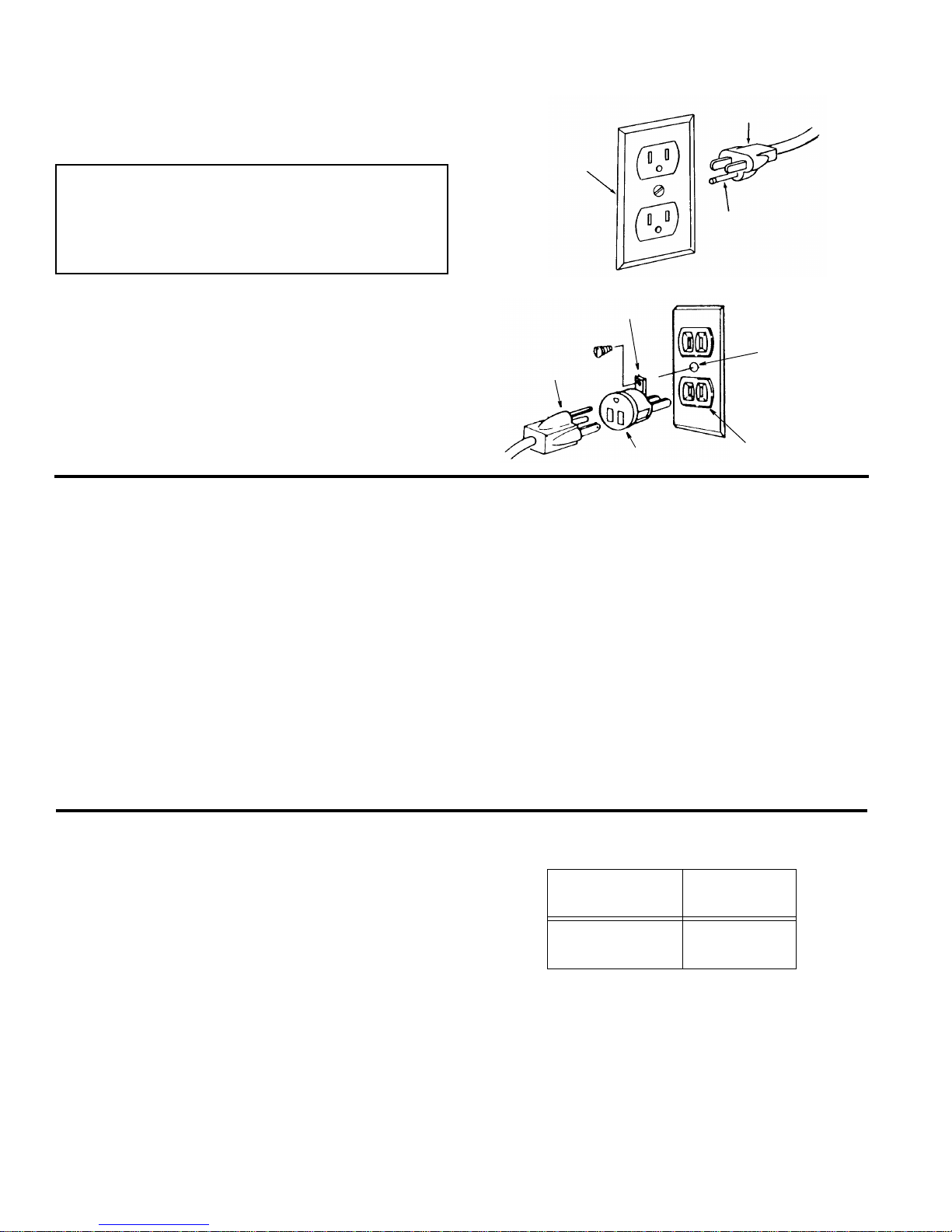
In the event of a malfunction or breakdown, grounding
provides a path of le ast resistance for electric curre nt to
reduce the risk of electric shock. This tool is equipped
with an electric cord having an equipment grounding conductor and a grounding plug, as shown. The plug must be
plugged into a mat ching outlet that is properly installed
and grounded in accordance with all local codes and
ordinances.
Do not modify the plug pr ovide d. I f i t wi ll not fi t the ou tle t,
have the proper outlet installed by a qualified electrician.
A temporary ad apte r m ay be used t o co nne ct this plug to
a 2-prong outlet, as shown, if a prope rly grounded three
prong outlet is not available. This temporary adapter
should be used only until a properly grounded three
prong outlet can be installed by a qualified electrician.
The green colored rigid e ar, lug and the like, extending
from the adapter must be connected to a permanent
ground such as a properly grounded outlet box.
NOTE: In Canada the use of a temporar y adapter is not
permitted by the Canadian electrical code.
Improper connection of the equipment grounding conductor can result in a r isk of electri c shock. The conductor with insulation having an outer surface that is green
with or without yellow stripe s is the equipmen t grounding
conductor. If repair or replacemen t of the electr ic cord or
plug is necessary, do not connect the equipme nt- grounding conductor to a live terminal.
Rated H.P
1/2
Voltage 110-120
Amperes 8.2
Hertz (Cycles) 60
Phase Single
RPM 1725
Rotation of Shaft
Clockwise
6
Motor Specifications and Electrical Requirements (continued)
If the grounding instructions are not completely understood, or if you are in doubt as to whether the tool is properly grounded check with a qualified electrician or service
personnel.
WARNING: If not properly grounded, this tool can
cause an electrical shock, particularly when used
in damp locations, in proximity to plumbing, or out
of doors. If an electrical shock occurs there is the
potential of a secondary hazard, such as your
hands to hit the cutting tool.
NOTE: The adapter illustrated is for use only if you already
have a p r ope rly gr o und ed 2- p rong ou tl et.
NOTE: In Canada the use of a temporary adapter is not
permitted by t he Canad ian Ele c trical C ode.
Motor Safety Protection
IMPORTANT: To avoid motor damage, this moto r should
be blown out or vacuumed frequently to keep sawdust
from interfering with normal motor ventilation.
1. Connect this tool to a power source with the approp riate voltage for your model and a 15-amp branch circuit
with a 15-amp time de lay fuse or ci rcu it breaker. Using
the wrong size fuse can damage the motor.
2. If the motor won’t start, turn th e switch off immediately
and unplug the tool. Check the quill to make sure it
turns freely. If the quill is free, try to start the motor
again. If the motor still does not start, refer to the
"Motor Troubleshooting Chart."
3. Fuses may "blow" or circuit breakers may trip frequently if:
a. Motor Is Ove rloaded-Overloading c an occur if you
feed too rapidly or make too many star t/stops in a
short time.
b. Line voltages should not be more than 1 0% above
or below the nameplate voltage. For heavy loads,
however, the voltage at motor term inals must equal
the voltage specified for your model.
c. Improper or dull drill bit is used.
4. Most motor troubles may be traced to loose or incorrect connections, overload, low voltage (such as small
size wire in the supp ly circuit) or to overly long supply
circuit wire. Always check the connections, the load
and the supply circuit whenever motor doesn’t work
well. Check wire sizes and l ength with the Wire Size
Chart shown.
Wire Sizes
NOTE: Make sure the proper extension cord is used and
is in good condition.
The use of any extension cord will cause some loss of
power. To keep this to a minimum and to prevent overheating and motor burnout, use the table at right to determine the minimum wire size (A.W .G.) extension cord.
Use only 3-wire extension cords which have 3-prong
grounding type plugs and 3-pole receptacles which
accept the tools plug.
Properly
Grounded
Outlet
3-Prong Plug
Grounding
Prong
Grounding Lug
3-Prong
Adapter
2-Prong
Outlet
Make sure this
Is Connected
Ground
Plug
Green
to a Known
Extension Cord
Length
Gauge
(A.W.G.)
0-25
25-50
16
14
7
Unpacking and Checking Contents
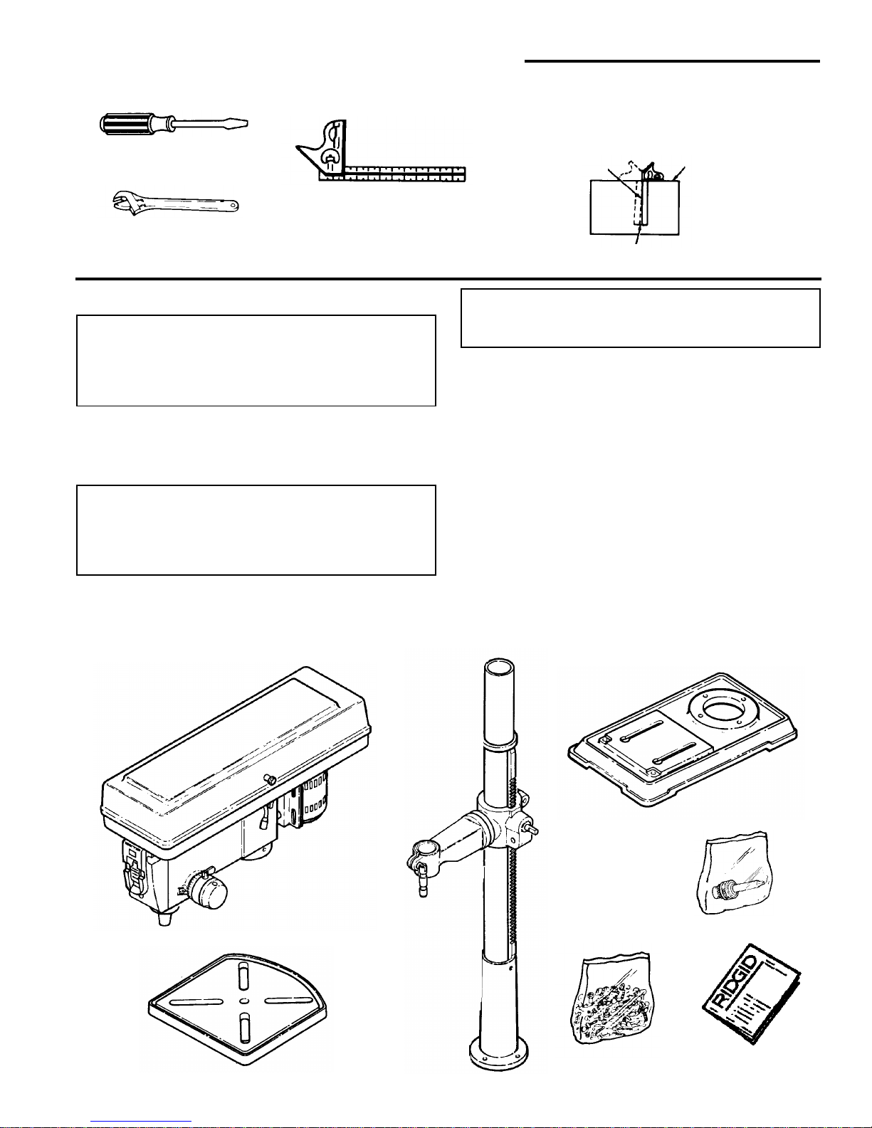
Tools Needed
Unpacking
WARNING: To reduce the risk of injury from unexpected starting or electrical shock, do not plug the
power cord into a source of power. This cord must
remain unplugged whenever you are working on
the drill press.
The Drill Press is shipped complete in one box.
1. Separate all “loos e parts” from packing ma terials and
check each item with illustration and “Table of Lo ose
Par t s.”
WARNING: To reduce the risk of injury, if any parts
are missing, do not attempt to assemble the drill
press, plug in the power cord, or turn the switch on
until the missing parts are obtained and installed
correctly.
2. Remove the protective oil that is applied to the table
and column. Use any o rdinary h ousehold type grease
and spot remover.
WARNING: To reduce the risk of fire or toxic reaction, never use gasoline, naptha or similar highly
volatile solvents to remove protective oil
3. Apply a coat of pa ste wax to the table and column to
prevent rust. Wipe all parts thoroughly with a clean dry
cloth.
NOTE: Make cer tain all items are accounted for, before
discarding any packing material.
List of Loose Parts
Item Description Qty.
A Head Asm. .........................................................1
B Table...................................................................1
C Column Support Assembly.................................1
D Base...................................................................1
E Bag Chuck/Arbor Assembly ...............................1
F Bag of Loose Parts.............................................1
G Owners Manual..................................................1
Combination Square
Combination Square Must be True
Draw Light
Line on Board
Along this Edge
Straight Edge of
Board 3/4” Thick
This Edge Must be
Perfectly Straight
Should be no Gap or Overlap when Square
is Flipped Over in Dotted Position
Medium Screwdriver
Adjustable Wrench
A
B
D
E
G
F
C
8
Unpacking and Checking Contents (continued)
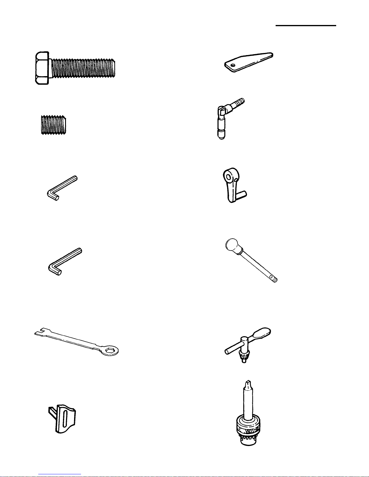
Loose Parts in Box and Bag
M10 x 1.5-40 Long
Hex Head Bolt (4)
(With Set Screw) (1)
Crank
M10 x 1.5-12 Long
Hex Socket Set Screw (2)
Chuck Key (1)
Chuck/Arbor (1)
M5 Hex “L” Wrench (1)
M24 Hex Box
Wrench (1)
Key Drift (1)
Key-Switch (1)
M3 Hex “L” Wrench (1)
Feed Handle (3)
Support Lock Handle (1)
Assembly
9
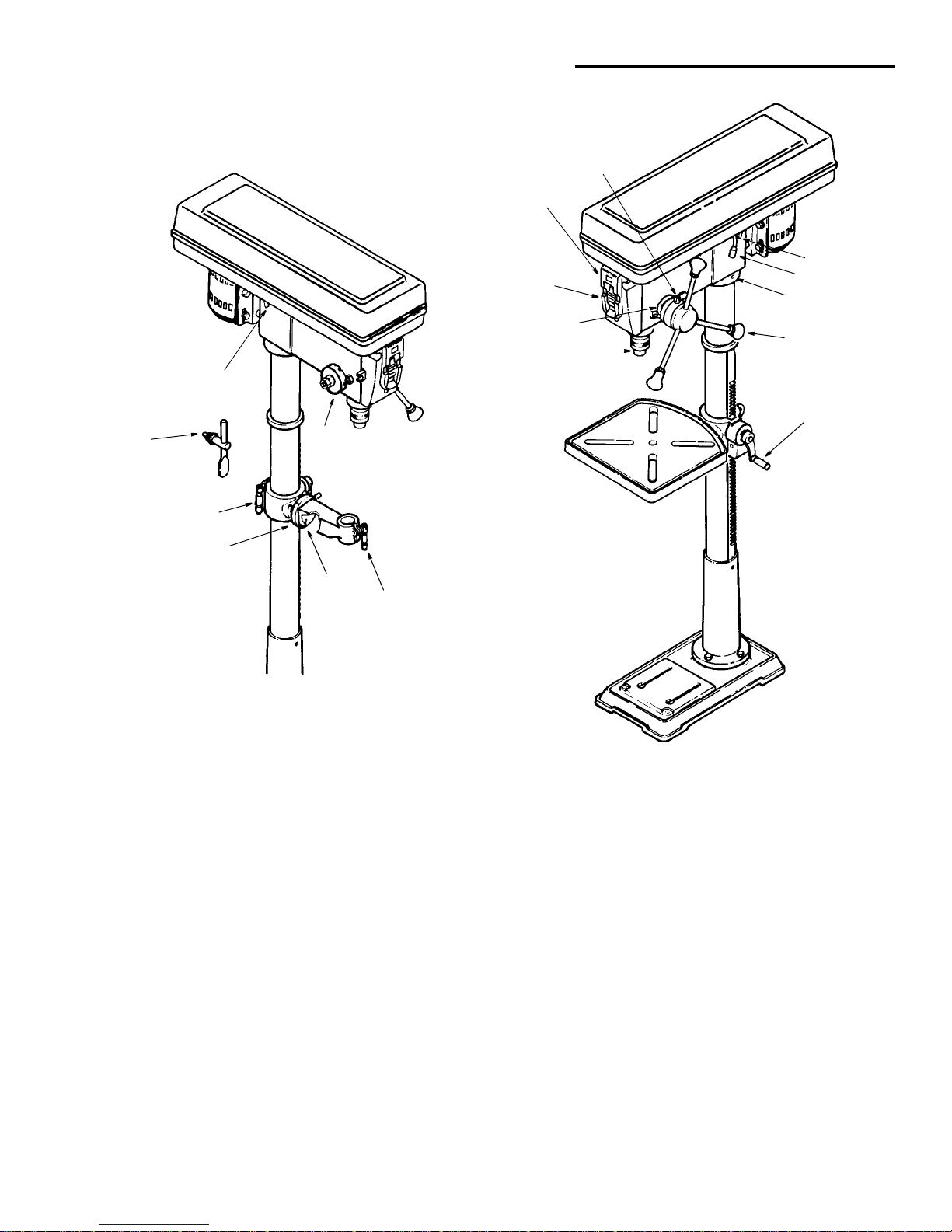
Location and Function of Controls
1. Belt Tension Lock Handles...Tightening handles
locks motor bracket support to maintain correct bel t
distance and tension.
2. Belt Tension Handle...T urn handle counterclockwise
to apply tension to belt, turn handle clockwise to
release belt tension.
3. Head Lock Set Screws...Locks the head t o the column. Always have them locked in place while operating the drill press.
4. Feed Handle...For moving the chuck up or down.
One or two of the handl es may be removed if ne cessary whenever the workpiece is of such unusual
shape that it interferes with the handles.
5. Table Crank...Tur n clockwise to elevate table. Support lock must be released before operating crank.
6. Chuck Key...Used to tighten drill in the chuck and
also to loosen the chuck for drill removal.
7. Chuck...Holds dr ill bit or oth er recomme nded acces sory to perform desired operations.
8. Depth Scale ...A llows operator to ad just dr ill pres s to
drill to a desired depth.
9. Drill “On-Off” Switch...Has locking feature to pre-
vent unauthorized and possible hazardous use by
children and others.
10. Light “On-Off” Switch...Turns the light on and off.
11. Depth Scale Lock...Locks the depth scale at
selected depth.
12. Spring Cap...Provides means to adjust quill spring
tension.
13. Table Lock...Allows table to be rotated in various
positions and locked.
14. Table Bevel Lock...Locks the table in any position
from 0°- 45°.
15. Bevel Scale...Shows degree table is tilted for bevel
operations. Scale is mounted on side of arm.
16. Suppor t Lock H andle...Tightening locks table support to column. Always have it locked in place while
operating the drill press.
Note and follow the safety warnings and instructions
that appear on the panel on the right side of the head.
1
12
13
14
15
16
Ta ble Remo ved
for Clarity
2
3
4
5
6
7
8
9
10
11
1
10
Assembly
WARNING: To reduce the risk of injury from unexpected starting or electrical shock, never connect
plug to outlet until all assembly steps are completed and you read and understand all instructions.
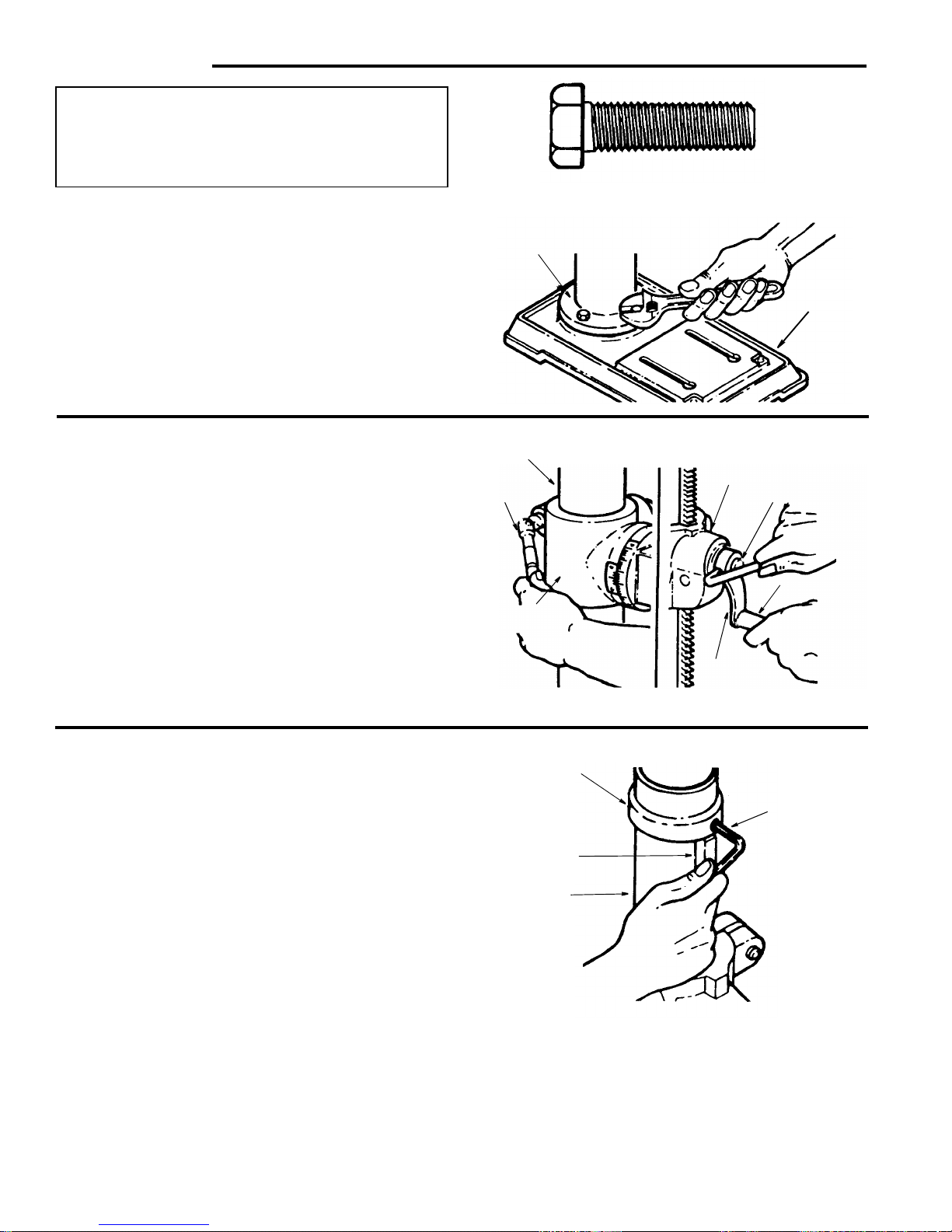
Assembly of Base/Column
1. Locate four (4) 10mm di a. x 40mm long bolts among
loose parts bag.
2. Po siti on b ase on f loo r. Remove prot ect iv e co v eri ng and
discard.
3. Remove protective sleeve from column tube and discard. Place column as sem bly on bas e, and align hol es
in column support with holes in base.
4. Install a bolt in each hole throug h column suppor t and
base and tighten with adjustable wrench.
5. Locate table crank and support lock in loose parts box.
6. Install support lock from left side into table support and
tighten by hand.
7. Install table crank asse mbly and tighten set screw with
a 3mm hex “L” wrench. Do no t overtighten. Se t screw
should be tightened against the flat section of the
shaft.
NOTE: To minimi ze crank backla sh, tig hten s upport lock,
rotate elevation worm shaft clockwise, then assemble
crank tight against table support and tighten set screw.
8. Check column collar for proper adjustment. Collar
should not be angle d on the column and it shoul d be
positioned so rack will slide freely in collar when table
is rotated 360° ar oun d col um n tube. If readjusted, only
tighten set screw enough to keep collar in place.
NOTE: To reduce the risk of column or collar damage, do
not overtighten set screw.
Column
Support
Base
Column
Support
Lock
Table
Support
Table
Support
Elevation
Worm Shaft
Handle
Table
Crank
10mm Dia. x 40mm
Hex Head Bolt (4)
Column
Collar
Rack
Column
Do Not
Overtighten
Set Screw
 Loading...