

Page 1

OPER
0.0°
A
TOR’S MANUAL
UNIVERSAL DIGITAL MITER GAUGE
DMG9015
W
ARNING:
To reduce the risk of injury, the user must read and understand the operator’s manual before using this product.
Thank you for buying a RIDGID product.
SAVE THIS MANUAL FOR FUTURE REFERENCE
Page 2

TABLE OF CONTENTS
n General Safety Instructions ........................................................................3
Safety Symbols ...................................................................................3
Damage Prevention and Information Messages .........................................................3
Safety Precautions for Operations .................................................................... 3
Service Safety .................................................................................... 3
n Unpacking and Checking Contents .................................................................4
Unpacking .......................................................................................4
List of Contents ..................................................................................4
n Getting to Know Your Digital Miter Gauge ...........................................................5-6
Main Parts ....................................................................................... 5
Technical Specications ............................................................................ 6
n Operation ......................................................................................7-9
To Install Batteries ................................................................................ 7
Attach the Fence to the Miter Gauge Head .............................................................7
Choose the Proper Gauge Bar Attachment ............................................................. 8
Adjust the T-slot Washer to the Correct Position .........................................................8
Turn the Digital Miter Gauge On and Off ............................................................... 9
Flip the Display ................................................................................... 9
Calibrate the Digital Miter Gauge to the Table-Saw-Blade Assembly .........................................9
Audio Feedback .................................................................................. 9
n Application ...................................................................................10-12
Cut Wood at Any Angle with ±0.1º Accuracy ...........................................................10
Use the Precision Fence Accessories ................................................................ 10
Set the Table-Saw-Blade Tilt Angle .................................................................. 11
n Maintaining Your Digital Miter Gauge ............................................................... 13
n Troubleshooting ................................................................................ 13
n Warranty. . . . . . . . . . . . . . . . . . . . . . . . . . . . . . . . . . . . . . . . . . . . . . . . . . . . . . . . . . . . . . . . . . . . . . . . . . . . . . . . . . . . . . . 14
2
Page 3

GENERAL SAFETY INSTRUCTIONS
The purpose of safety symbols is to attract your attention to
possible dangers. The safety symbols and the explanations
with them deserve your careful attention and understanding.
The symbol warnings DO NOT, by themselves, eliminate
any danger. The instructions and warnings they give are no
substitutes for proper accident prevention measures.
Safety Symbols
SAFETY ALERT SYMBOL:
Indicates DANGER, WARNING, OR CAUTION; may be
used in conjunction with other symbols or pictographs.
DANGER:
Failure to obey this safety warning WILL result in death
or serious injury to yourself or to others. Always follow
the safety precautions to reduce the risk of fire, electric
shock, and personal injury.
WARNING:
Failure to obey this safety warning CAN result in
death or serious injury to you or to others. Always
follow the safety precautions to reduce the risk of
fire, electric shock, and personal injury.
CAUTION:
Failure to obey this safety warning MAY result in personal injury to yourself or to others or property damage.
Always follow the safety precautions to reduce the risk
of fire, electric shock, and personal injury.
Damage Prevention and Information
Messages
WARNING:
Always keep the miter fence away from the blade
when guiding the workpiece with this digital miter
gauge. Serious personal injury may result if the
metal fence comes in contact with the blade.
WARINING:
Before setting blade-tilt angle, make sure that the table
saw switch is in the OFF position and the plug is not
connected to a power source. Serious personal injury
may result if the saw is started by accident.
Safety Precautions for operations
•Do not use this tool for any purpose other than those out-
lined in this manual. This could result in serious injury.
•Keep the tool dry, and do not use it in the rain.
•Avoid dropping the tool and other causes of impact on the
tool.
•Remove the batteries if the device will not be used for
several days.
•Always dispose of the used batteries according to your
local ordinance; do not incinerate the batteries.
•Thedigitalmitergauge must be calibrated before using it
to set up cuts or set the saw blade angle.
Service Safety
Do not attempt to repair or disassemble the Digital Miter
Gauge. If unqualied persons attempt to repair this product,
serious injury may occur. Any repair required should be performed only by authorized service personnel.
These inform the user of important information and/or instructions that could lead to equipment or other property
damage if they are not followed. Each message is preceded
by the word “NOTE,” as in the example below:
NOTE: Equipment and/or property damage may result if
these instructions are not followed.
WARNING:
Be sure to read and understand all safety instructions
in this manual and the manual for your power tool, including all safety alert symbols, such as “DANGER,”
“WARNING,” and “CAUTION,” before using this Digital
Miter gauge. Failure to follow all instructions listed below and in the instructions for your power tool may result in electric shock, fire, and/or serious personal
injury.
3
Page 4

UNPACKING AND CHECKING CONTENTS
The Digital Miter Gauge comes in one box. Do not discard
any packing materials until all of the contents are accounted
for.
Separate all the parts from the packing materials. Refer to
the”List of Contents” and Fig. 1 to make certain that all the
items are accounted for before discarding any packing material. Call the RIDGID Service Center if any parts are damaged or missing.
List of Loose Parts
Part Name QuaNtity
Digital Miter Gauge 1
Miter Fence 1
Micro-adjust Gauge 1
Flip Stop Gauge 1
Precision Stop Gauge 1
1/4” Gauge bar attachment (installed on the
gauge bar)
1/8” Gauge bar attachment 1
Magnetic blade attachment 1
Hex wrench 1
T-slot washer for 3/8” depth slot (installed
on the gauge bar)
T-slot washer for 1/2” depth slot 1
Screw for Deep T-slot washer 1
AAA Batteries 2
1
1
4
Page 5
GETTING TO KNOW YOUR DIGITAL MITER GAUGE
The digital miter gauge is a smart tool that increases efciency in woodworking projects. It was designed by a professional
woodworker for woodworkers. It sets crosscut angles and table saw blade angles from -50° to +50° with ±0.1° accuracy in
a matter of seconds. For use with all bench, portable, and stationary table saws with 1/2", 5/8", and 3/4" slots and 5/8", 3/4",
and 7/8" T-Slots with the slot depth of 3/8" or 1/2".
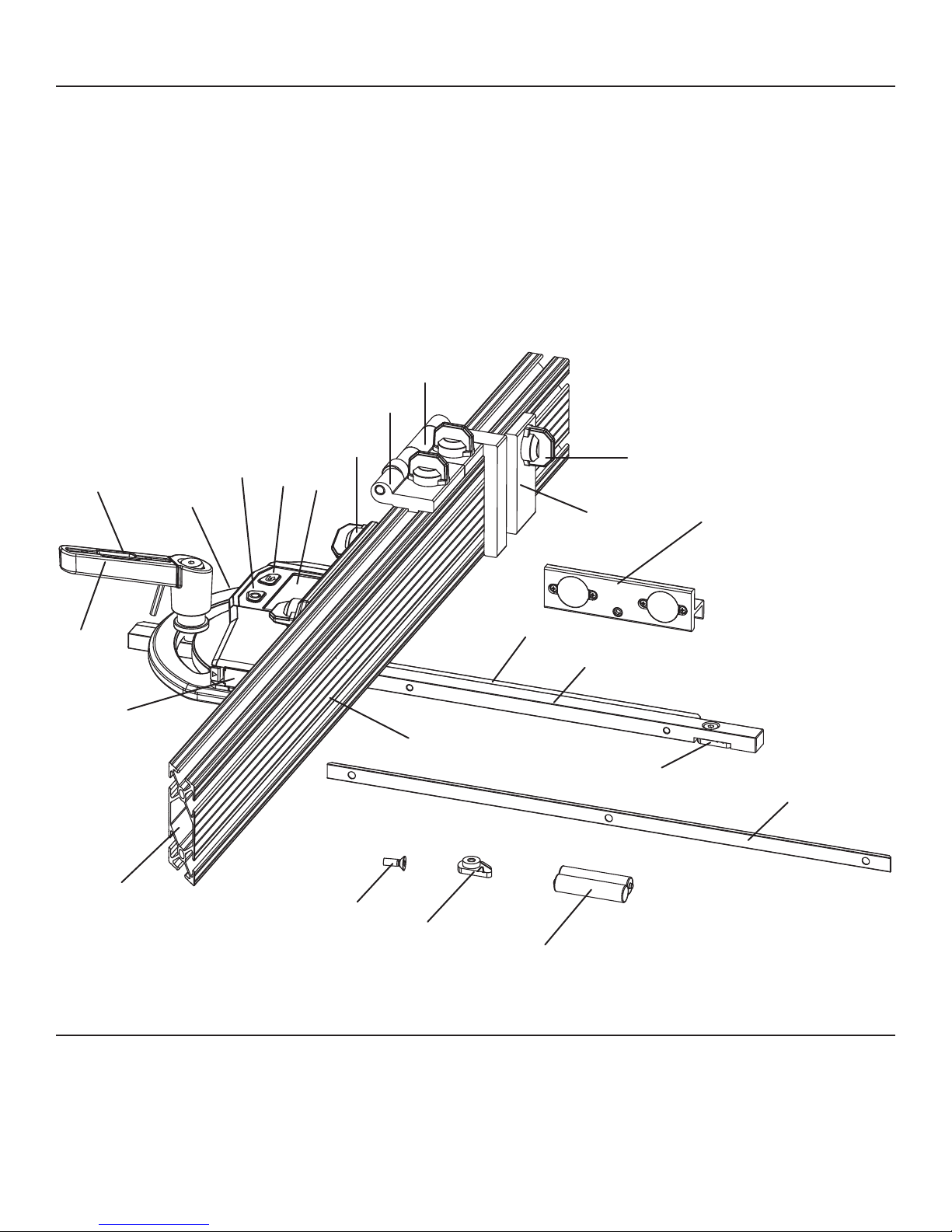
Main parts
10
9
5
2
3
8
1
7
6
21
4
16
14
12
20
19
18
11
5
13
15
17
Fig. 1
5
Page 6

GETTING TO KNOW YOUR DIGITAL MITER GAUGE
1. Machined Miter Gauge head
2. Power button: press to turn on the digital miter gauge;
press again to ip the display;
3. ZERO Button: calibrates the current angle as 0.0 de-
gree.
4. LCD Screen: large LCD display with blue back lighting
for easy reading.
5. Fence-Lock Knobs: secures the miter fence to the mi-
ter gauge head; secures the stop gauges to the miter
fence.
6. Battery Compartment: for two AAA batteries.
7. Soft Grip Locking Handle: locks and unlocks the miter
gauge head.
8. Hex Wrench: used to loosen or tighten the screws on
gauge bar attachments, magnetic blade attachment
and T-slot washer.
9. Micro-adjust Gauge: designed to be used in any of the
fence grooves, it can be used as a micro adjust for the
ip stop or a positive stop gauge.
10. Flip-Stop Gauge: a multi-use gauge that can be used in
any fence groove and as a solid stop gauge.
11. Precision Stop Gauge: For accurate repetitive cuts.
12. Miter Fence: guides the workpiece for cutting at the se-
lected angle.
13. Magnetic Blade Attachment: attaches to the 1/2” miter
gauge bar for blade -tilt adjustment.
14. 1/2” Miter Gauge Bar: ts all bench, portable, and sta-
tionary tools with a standard 1/2” miter gauge slot.
15. T-slot Washer for 3/8” depth slot: ts in T-slot tables of
bench, portable, and stationary tools with a slot depth
of 3/8”.
16. 1/4” Gauge Bar Attachment: attaches to the 1/2” miter
gauge bar to t all bench, portable, and stationary table
saws with 3/4” slot.
17. 1/8” Gauge Bar Attachment: attaches to the 1/2” miter
gauge bar to t all bench, portable and stationary table
saws with 5/8” slot.
18. Batteries
19. T-slot Washer for 1/2” depth slot: ts in T-slot tables of
bench, portable, and stationary tools with a slot depth
of 1/2”.
20. Screw for Deep T-slot Washer
21. Mitered end: permits precise miter cuts close to the
end of the miter fence.
Technical Specifications
Battery 2 “AAA” 1.5V batteries
Miter angle range -50° to +50°
Blade tilt angle range -50° to +50°
Accuracy ±0.1°
Optimum Operating
Temperature Range
Weight 3.67 lbs ( 1.67 kg)
32°F to 104°F (0°C to 40°C)
6
Page 7
OPERATION
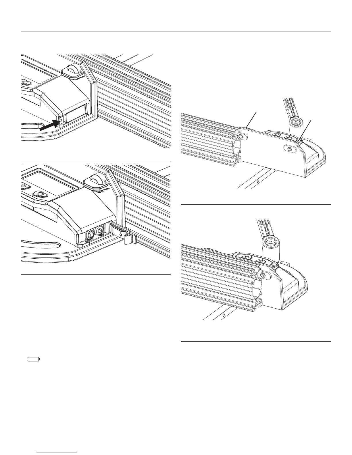
TO INSTALL BATTERIES
This digital miter gauge uses two ”AAA” batteries.
Fig. 2
ATTACH THE FENCE TO THE MITER GAUGE HEAD
The fence has a mitered end to permit precise miter cuts
close to the end of the miter fence. Always position this
end to right side of the miter head. Refer to location 21 in
Fig. 1.
1. Loosen the fence-lock knobs (5 in Fig. 1) to release
both lock blocks so they may be inserted into the slot
in the fence.
fence-lock knob
fence-lock
knob
Fig. 4
Fig. 3
1. Open the battery cover as indicated by the arrow on the
cover (Fig. 2).
2. Insert two new “AAA”alkaline batteries according to the
polarity indicators in the battery compartment(Fig. 3). Be
sure the polarity (+/-) is correct!
3. Close the cover and lock it securely in place.
NOTE:
•Replacethebatterieswhenthebatteryindicatoronthe
display indicates that the batteries are fully depleted:
" ".
•Removethebatteriesfromthedigitalmitergaugewhenit
is not used for extended periods.
•The2AAAbatteriesshouldmatcheachotherinbrand
and type.
•Donotmixoldandnewbatteries.
•Removedepletedbatteriesimmediately,anddisposeof
them according to your local ordinance.
•Neverdisposeofbatteriesinre.
2. Align the rst lock block with the slot in the fence and
slide it into place (Fig. 4).
Fig. 5
3. Continue to slide the second lock block into place
(Fig.5).
4. Move the fence to the desired position.
5. Turn the fence-lock knobs clockwise to lock the fence.
7
Page 8
OPERATION
1/2” gauge bar
1/8” gauge bar
attachment
1/4” gauge bar
attachment
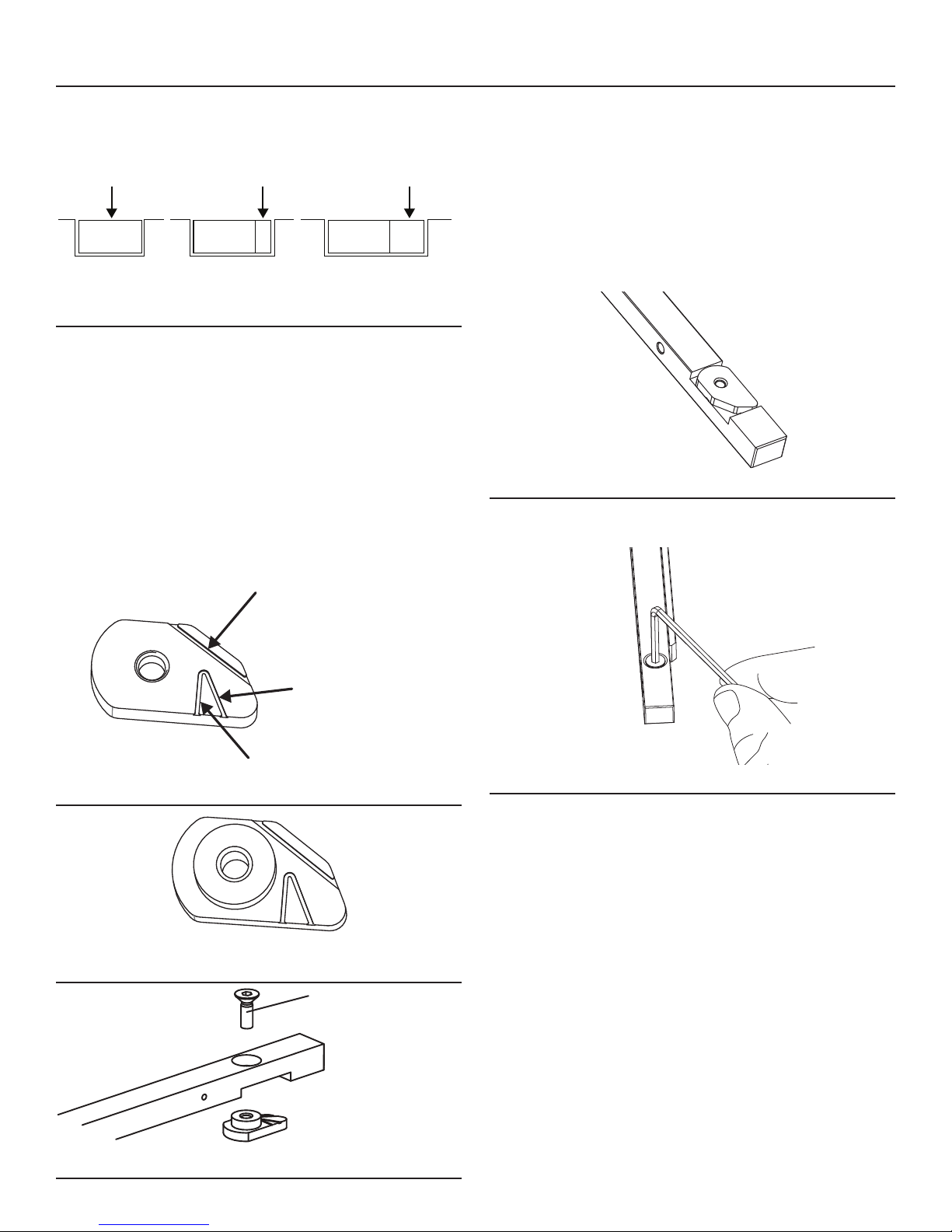
1/2” slot 5/8” slot 3/4” slot
CHOOSE THE PROPER GAUGE BAR ATTACHMENT
Fig. 6
The gauge bar attachments adapt the universal gauge bar
to t in standard 1/2”, 5/8” or 3/4” miter gauge slots. The
universal gauge bar ts a 1/2” slot. Using the hex wrench
and the screws provided, attach a 1/8” gauge bar attachment on the side to t in a 5/8” slot; attach a 1/4” gauge
bar attachment on the side to t in a 3/4” slot. Please refer
to Fig. 6.
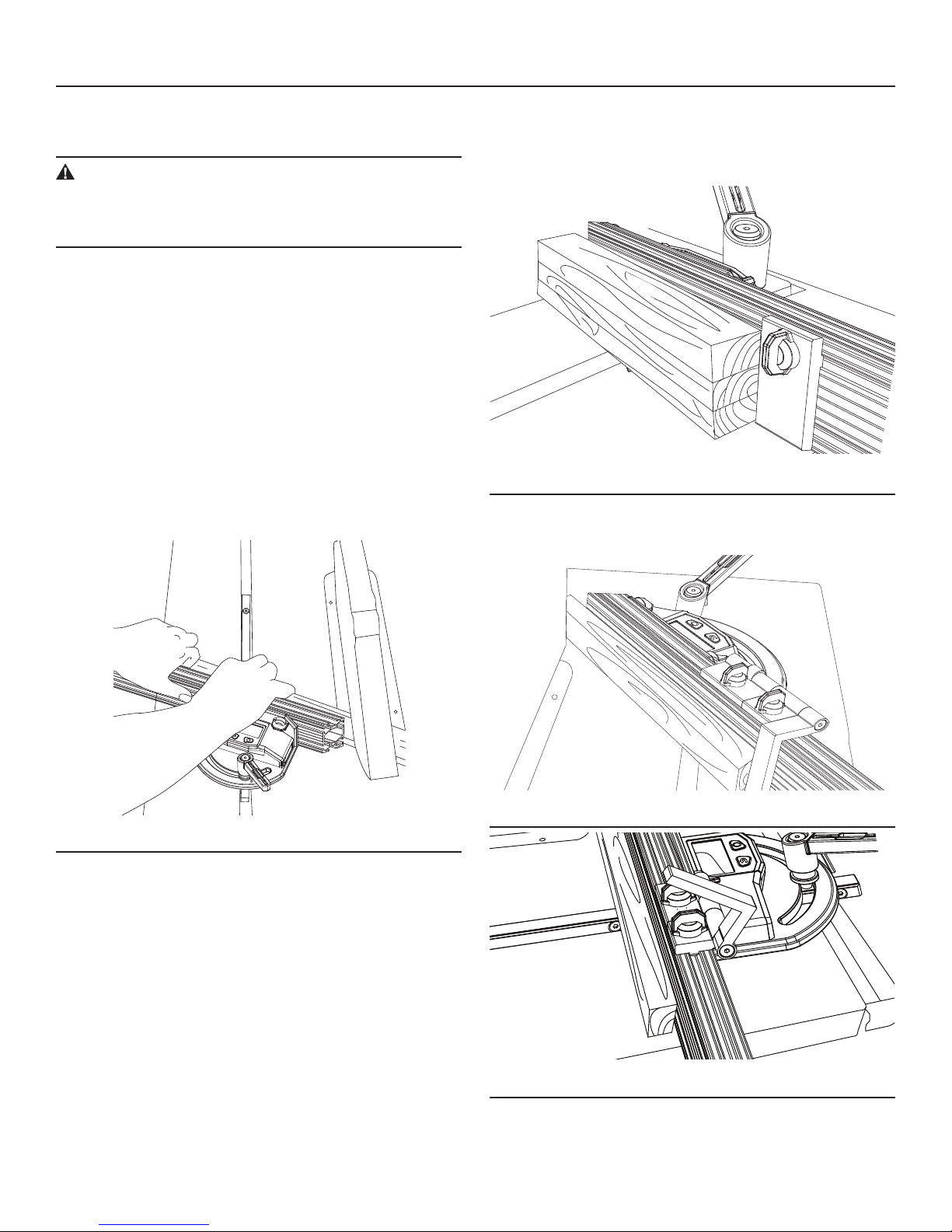
ADJUST THE T-SLOT WASHER TO THE CORRECT POSITION
Adjust the T-slot washer to allow the gauge bar to t in the
slots of T-slot tables and non T-slot tables on bench, portable, and stationary tools.
The 3/8” T-slot washer (Fig. 7a) is attached to the front side
of the gauge bar (Fig. 8). Use this washer for T-slots that
are 3/8” deep. For T-slots that are ½” deep, remove the
3/8” washer and attach the ½” T-slot washer (Fig. 7b & Fig.
7c).
There are three indicating lines on each washer (Fig. 7a);
use these lines to guide you as you turn the washer to a
specied position to it t a standard 5/8”, 3/4” or 7/8” Tslot table.
Fig. 8
To t non T- slot tables, keep the two sides of the T-washer
aligned with the gauge bar, as shown in Fig. 8.
Indicating line for
5/8" T-slot
Indicating line for
3/4" T-slot
Indicating line for
7/8" T-slot
Long screw for deep
T-slot washer
Fig. 7a
Fig. 7b
Fig. 9
To t a T-slot table:
1. Loosen the screw on the T-slot washer with the hex
wrench (Fig. 9).
Fig. 7c
8
Page 9
OPERATION
°
0‘0
7/8” T-slot3/4” T-slot5/8” T-slot
a b c
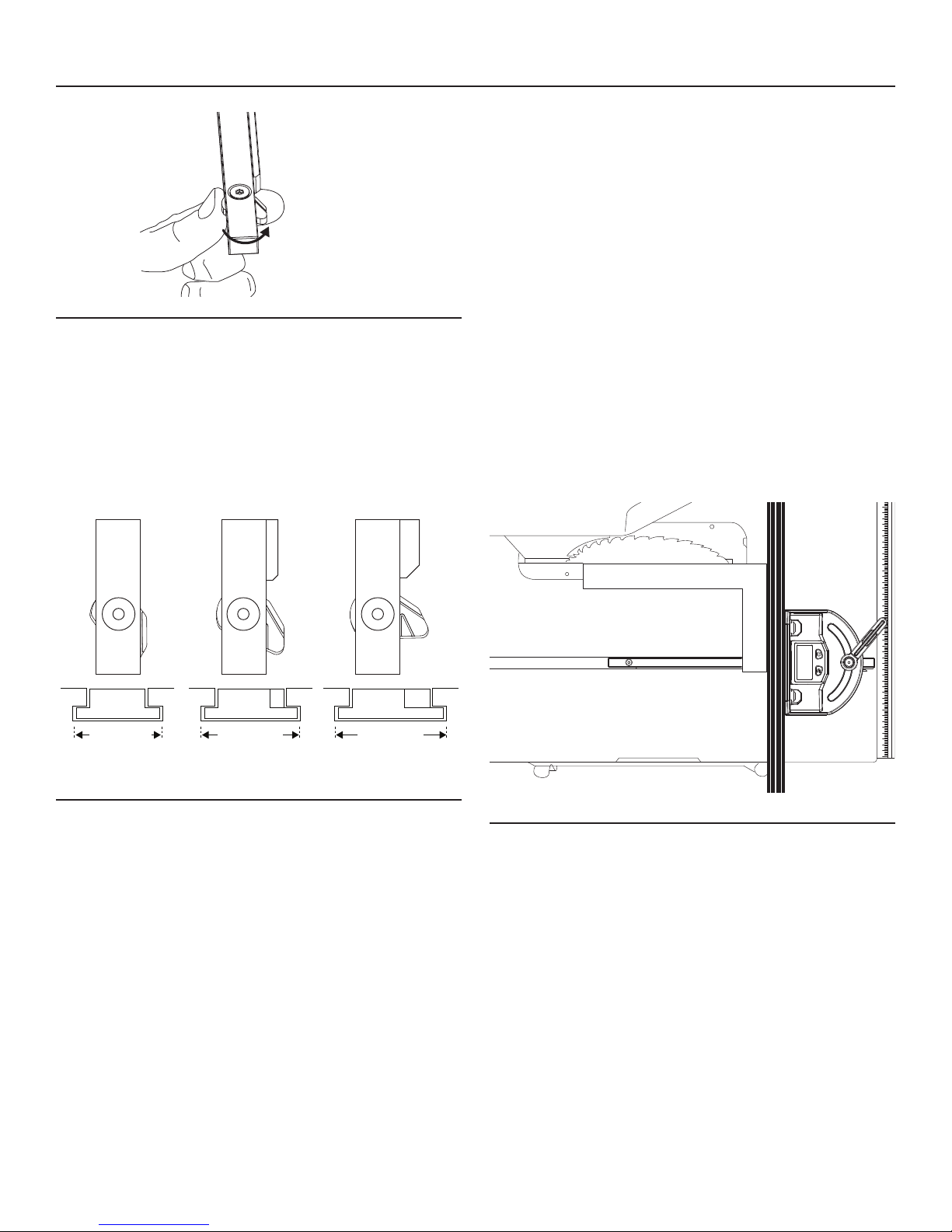
Fig.10
2. Turn the T-slot washer counter-clockwise and align the
indicating line with the edge of the gauge bar (Fig. 10 and
Fig. 11).
Fig. 11(a) shows the position of the T-slot washer to t a
standard 5/8” T-slot table.
Fig. 11(b) shows the position of the T-slot washer to t a
standard 3/4” T-slot table.
Fig. 11(c) shows the position of the T-slot washer to t a
standard 7/8” T-slot table.
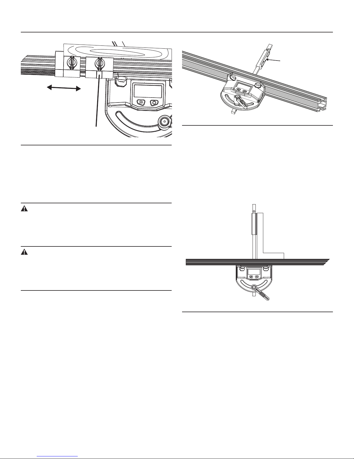
CALIBRATE THE DIGITAL MITER GAUGE TO
THE TABLE-SAW BLADE ASSEMBLY
(Carpenter’s square, available separately, required)
NOTE:
•Alwayscalibratethedigitalmitergaugetoyourtablesaw
before using this miter gauge to guide a cut. Failure to
perform the calibration may result in an inaccurate cutting.
•Oncethedigitalmitergaugehasbeencalibratedtoyour
table saw, no additional calibration is needed with subsequent use on the same table saw, unless the miter gauge
was calibrated to other table saws or carpenter’s square
after the rst calibration.
1. Slide the gauge bar into the groove on the T-slot in the
table or place the bar in the groove on a non T-slot table.
2. Fully raise the table-saw blade.
3. Loosen the locking handle.
4. Turn the miter gauge on.
3. Tighten the screw again with the hex wrench.
TURN THE DIGITAL MITER GAUGE ON AND
OFF
1. Press the Power button to turn on the tool.
2. Press the Power button for about 3 seconds to turn off
the tool.
3. The digital miter gauge will automatically turn itself off 5
minutes after the user stops moving the miter gauge
head.
FLIP THE DISPLAY
After the digital miter gauge is turned on, briey press the
Power key to ip the display.
Fig.11
Fig.12
5. Place a carpenter’s square rmly against the blade and
the miter fence (Fig. 12).
6. Press the Zero button for 2 seconds; the LCD will display
0.0º. The miter gauge is now calibrated to your table saw.
You may proceed to use the digital miter gauge for angle
cutting.
AUDIO FEEDBACK
During operation, the digital miter gauge produces an audible “click” as it swivels to the left or to the right. This feature
alerts the operator that the digital miter gauge is working
properly.
9
Page 10
APPLICATION
°
0’52
CUT WOOD AT ANY ANGLE WITH ±0.1º ACCURACY
WARNING:
Always keep the miter fence away from the blade when
guiding the cut with this digital miter gauge. Serious
personal injury may result if the metal fence is cut.
NOTE:
Before making any cuts, the digital miter gauge must rst be
calibrated.
1. Fit and calibrate the digital miter gauge to the table as
described in the preceding section, "CALIBRATE THE
DIGITAL MITER GAUGE TO THE TABLE-SAW-BLADE
ASSEMBLY.”
2. With the miter gauge bar securely in the table groove, turn
the digital miter gauge on.
3. Unlock the locking handle.
4. Swivel the miter gauge head to the desired angle, as indi-
cated in the display, and then tighten the locking handle.
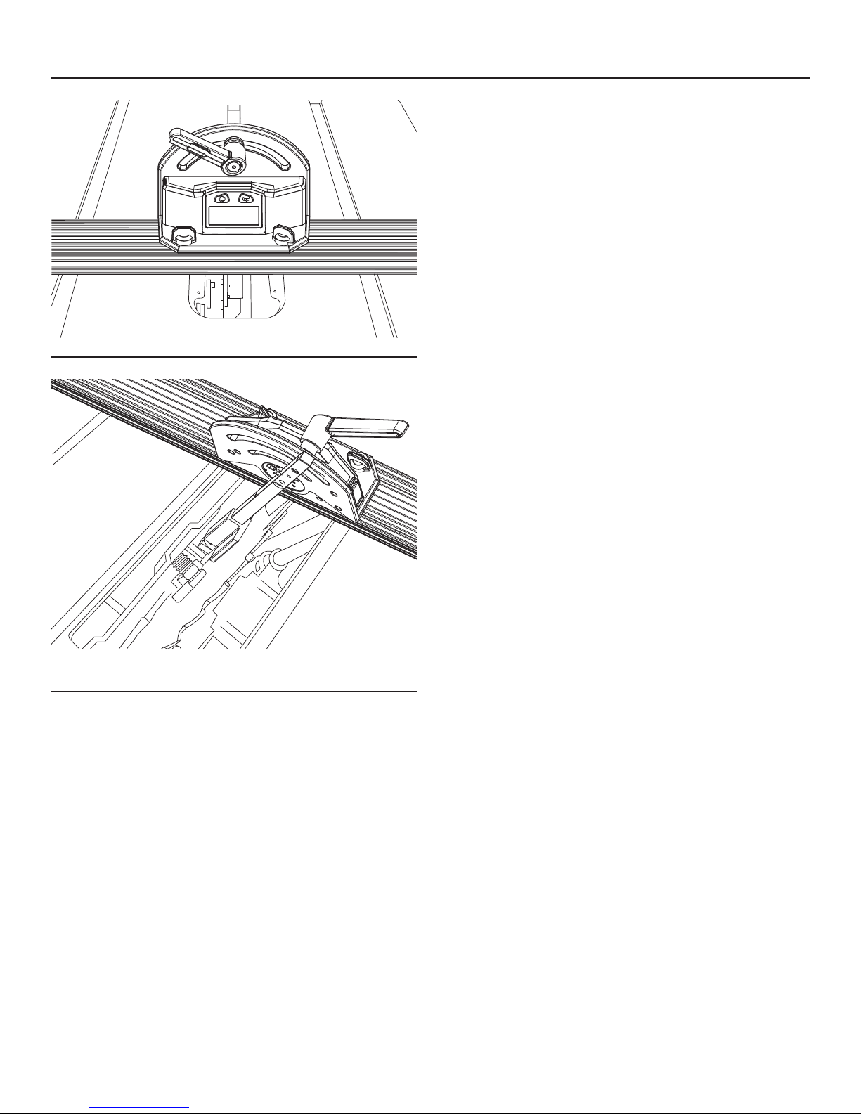
USE THE PRECISION FENCE ACCESSORIES
This digital miter gauge offers a variety of precision fence
accessories which will allow the user to fully utilize the miter
gauge capabilities.
Fig.14
The precision stop gauge is designed for vertical precision;
it allows the user to cut multiple pieces with one pass, as
shown in Fig. 14.
5. Securely place the workpiece against the miter fence and
begin crosscutting, following the operating instructions
for the table saw (Fig. 13).
Fig.15
Fig.13
Fig.16
The Flip Stop Gauge is a multiuse gauge, which can be used
in the top fence groove and as a solid stop gauge. To cut a
long workpiece, just ip it back, there is no need to detach it
from the fence (Fig. 15 and 16).
10
Page 11
APPLICATION
45,0°
0.0°
0.0°
Orient the magnets to
the correct side
Fig.18
Micro-adjust screw
Fig.17
The Micro-adjust Gauge is designed to be used in any of the
fence grooves; it can be used as a micro-adjust for the ip
stop or as a positive stop gauge. To adjust the ip stop
gauge, rst lock the micro-adjust gauge on the fence with
the lock knob, then turn the micro-adjust screw to move the
ip stop gauge left or right (Fig. 17).
SET THE TABLE-SAW BLADE TILT ANGLE
WARNING:
Before setting blade-tilt angle, make sure that the table-saw switch is in the OFF position and the plug is
not connected to a power source. Serious personal injury may result if the saw is accidentally started.
WARNING:
Remove the hex wrench from the locking handle and
put it in a safe place.
Serious personal injury may result if the hex wrench falls
into the table saw.
The magnetic blade attachment properly ts only the 1/2”
gauge bar, so detach any gauge bar attachment that is on
the gauge bar.
Use the magnetic blade attachment for table saw blades
that bevel to either the the left or the right.
1. Use the 1/8-in. hex wrench (included) to loosen the setscrew in the magnetic blade attachment in the counterclockwise direction.
2. For table saw blades that tilt "left," the magnets on the
attachment need to be oriented to the right side of the
gauge bar, as in Fig. 18. For table saw blades that tilt
"right," the magnets need to be oriented to the left side of
the gauge bar.
3. Tighten the setscrew.
4. Loosen the locking handle clockwise.
Fig.19
5. Place a carpenter’s square rmly against the magnetic
attachment and the miter fence. Press the Power button
to turn the digital miter gauge on. Press the Zero button
for 2 seconds to calibrate the gauge: the LCD will display
0.0º (Fig. 19).
6. Remove the table-saw insert.
7. Lower the table-saw blade to its lowest setting.
8. Loosen the fence-lock knobs and slide the miter gauge
head to the middle of the miter fence. Retighten the fencelock knobs.
11
Page 12
APPLICATION
0.0°
Fig.20
9. Lower the gauge bar into the table-saw-blade assembly
opening and allow the magnets to attach to the blade.
Always position the magnetic blade attachment close to
the center of the blade to keep the gauge bar from contacting the lower guard. Do not tighten the locking handle
(Fig. 20 and 21).
NOTE:
Be careful not to place the magnets near or on the saw blade
teeth.
10. Set the blade tilt angle by using your table saw controls
to adjust the blade to the desired angle, as indicated in
the miter-gauge display. If desired, ip the display by
briey pressing the Power button again.
NOTE:
In the process of moving the blade, ensure that the magnets
are always attached to the blade. If the magnets separate
from the blade, an inaccurate setting will result.
11. Remove the miter gauge and replace the table-saw in-
sert according to the table saw’s instruction manual before beginning to cut.
Fig.21
12
Page 13

MAINTENANCE
This tool has been designed to be a low-maintenance tool. However, in order to maintain its performance, you must always follow these simple directions.
•Avoidexposingthetooltoshock,continuousvibration,orextremehotorcoldtemperature.
•Storethetoolindoorsandinasafeplace.
•Alwayscleanthetoolwithaclean,softcloth.Ifnecessary,slightlymoistentheclothwithpurealcoholoralittlewater.
•Checkthebatteriesregularlytoavoiddeterioration.Alwaysremovethebatteriesfromthetoolifitisnotgoingtobeused
for an extended period of time.
•Replacethebatterieswhenthebatteryicondisplayedonthescreenindicatesthattheyarefullydepleted:" ".
•Donotattempttochangeanypartoftheunit.
•ToolservicemustbeperformedonlybyqualiedRepairCenter.Serviceormaintenanceperformedbyunqualiedper-
sonnel could result a risk of injury.
TROUBLESHOOTING
TROUBLE PROBABLE CAUSE SOLUTION
Batteries are installed incorrectly. Reinstall batteries with correct polarity.
The LCD screen will not turn
on.
The LCD display does not
operate correctly.
Inaccurate cutting angle or tilt
setting.
Battery voltage is low.
The LCD screen is damaged Take tool to the Service Center.
Batteries are depleted. Replace with new batteries.
The digital miter gauge was not calibrated to your table saw.
Replace with new batteries when the empty
battery icon appears on LCD.
Ensure that your miter gauge has been calibrated to the table saw prior to use
13
Page 14

NOTES
14
Page 15

RIDGID® DIGITAL MITER GAUGE
LIMITED THREE YEAR WARRANTY AND
90 DAY SATISFACTION GUARANTEE POLICY
America, Inc. All warranty communications should be directed to 1-800-4-RIDGID
(1-800-474-3443).
90-Day Satisfaction Guarantee Policy
During the rst 90 days after the date of purchase, if you are dissatised with the
performance of this RIDGID® tool for any reason, you may return the tool to the
dealer from which it was purchased for a full refund or exchange. To receive a
replacement tool you must present proof of purchase and return all original equipment packaged with the original product. The replacement tool will be covered by
the limited warranty for the balance of the three year warranty.
What is covered under the Limited Three Year Warranty
This warranty covers all defects in workmanship or materials in this RIDGID® tool
for the three year period from the date of purchase. This warranty is specic to
this tool. Warranties for other RIDGID® products may vary.
Important:
To speed up the warranty process, log onto the RIDGID® website at www.ridgid.com
or call 1-800-4-RIDGID within 30 days of purchase to register your Ridgid® tool and
validate your warranty. Please keep a copy of your receipt for your records and to
make a claim on your warranty.
What is not covered
This warranty applies only to the original purchaser at retail and may not be transferred. This warranty only covers defects arising under normal usage and does not
cover any malfunction, failure or defect resulting from misuse, abuse, neglect,
sentations or promises as to the quality or performance of its power tools other than
those specically stated in this warranty.
Additional Limitations
To the extent permitted by applicable law, all implied warranties, including warranties of or are dis-
claimed. Any implied warranties, including warranties of merchantability or tness
for a particular purpose, that cannot be disclaimed under state law are limited to
sible for direct, indirect, incidental or consequential damages. Some states do not
allow limitations on how long an implied warranty lasts and/or do not allow the exclusion or limitation of incidental or consequential damages, so the above limitations may not apply to you. This warranty gives you specic legal rights, and you
may also have other rights which vary from state to state.
© 2007 RIDGID, INC.
Model No. DMG9015
Serial No. _____________________
The model and serial numbers may be found on a plate attached to the saw at
the rear of the tile saw base. You should record both model and serial number
in a safe place for future use.
Questions or comments? Call:
1-800-4-RIDGID (1-800-474-3443) or go on-line at www.ridgid.com.
Please have your Model Number and Serial Number on hand when calling.
15
Page 16

MANUEL DE L’OPÉRATEUR
0.0°
JAUGE À ONGLETS NUMÉRIQUE
UNIVERSELLE
DMG9015
CONSERVEZ CE MANUEL POUR VOUS Y
RÉFÉRER ULTÉRIEUREMENT
MISE EN GARDE :
Pour réduire le risque de blessures, le consommateur doit lire et comprendre le manuel de l’opérateur avant d’utiliser ce
produit.
Merci d’avoir acheté un produit RIDGID.
CONSERVEZ CE MANUEL POUR VOUS Y RÉFÉRER ULTÉRIEUREMENT
Page 17

TABLE DES MATIÈRES
n Instructions de sécurité générales. . . . . . .. . . . . . . . . . . . . . . . . . . . . . . . . . . . . . . . . . . . . . . . . . . . .3
Symboles de sécurité. . . . . . . . . . . . . . . . . . . . . . . . . . . . . . . . . . . . . . . . . . . . . . . . . . . . . . . . . . . . . . . . . . .3
Message d’information et de prévention des dommages. . . . . . . . . . . . . . . . . . . . . . . . . . . . . . . . . . . . . . . 3
Précautions de sécurité relative à l’utilisation. . . . . . . . . . . . . . . . . . . . . . . . . . . . . . . . . . . . . . . . . . . . . . . . .3
Sécurité concernant l’entretien. . . . . . . . . . . . . . . . . . . . . . . . . . . . . . . . . . . . . . . . . . . . . . . . . . . . . . . . . . . . 3
n Déballage et vérification du contenu. . . .. . . . . . . . . . . . . . . . . . . . . . . . . . . . . . . . . . . . . . . . . . . . . . . . . . 4
Déballage. . . . . . . . . . . . . . . . . . . . . . . . . . . . . . . . . . . . . . . . . . . . . . . . . . . . . . . . . . . . . . . . . . . . . . . . . . . .4
Liste du contenu. . . . . . . . . . . . . . . . . . . . . . . . . . . . . . . . . . . . . . . . . . . . . . . . . . . . . . . . . . . . . . . . . . . . . . . .4
n Se familiariser avec votre jauge à onglets numérique. . . . . . . . . . . . . . . . . . . . . . . . . . . . . . . . . . . . . . . .5-6
Pièces principales. . . . . . . . . . . . . . . .. . . . . . . . . . . . . . . . . . . . . . . . . . . . . . . . . . . . . . . . . . . . . . . . . . . . . . 5
Caractéristiques techniques. . . . . . . . . . . . . . . . . . . . . . . . . . . . . . . . . . . . . . . . . . . . . . . . . . . . . . . . . . . . . . 6
n Fonctionnement. . . . . . . . . . . . . . . . . . . . . . . . . . . . . . . . . . . . . . . . . . . . . . . . . . . . . . . . . . . . . . . . . . . . . . .7-9
Installation des piles. . . . . . . . . . . . . . . . . . . . . . . . . . . . . . . . . . . . . . . . . . . . . . . . . . . . . . . . . . . . . . . . ... . . .7
Fixer le guide à la tête de la jauge à onglets. . . .. . . . . . . . . . . . . . . . . . . . . . . . . . . . . . . . . . . . . . . . . .. . . . . 7
Choisir la bonne attache pour la barre de la jauge. . . . . . . . . . . . . . . . . . . . . . . . . . . . . . . . . . . . . . . . . . . . . 8
Régler la rondelle pour rainure en T à la bonne position. . . . . . . . . . . . . . . . . . . . . . . . . . . . . . . . . . . . . .. . . .8
Allumer et éteindre la jauge à onglets numérique. . . . . . . . . . . . . . . . . . . . . . . . . . . . . . . . . . . . . . . . . . . . . . 9
Basculer l’afchage. . . . . . . . . . . . . . . . . . . . . . . . . . . . . . . . . . . . . . . . . . . . . . . . . . . . . . . . . . . . . . . . . . . . .9
Calibrer la jauge à onglets numérique sur l’assemblage de lame et de scie de table. . .. . . . . . . . . . . . . . . . 9
Rétroaction audio. . . . . . . . . . . . . . . . . . . . . . . . . . . . . . . . . . . . . . . . . . . . . . . . . . . . . . . . . . . . . . . . . . . . . . .9
n Application. . . . . . . . .. . . . . . . . . . . . . . . . . . . . . . . . . . . . . . . . . . . . . . . . . . . . . . . . . . . . . . . . . . . . . . . . . . 10-12
Couper le bois à un angle quelconque avec une précision de ±0,1o. . . . . . . . . . . . .. . . . . . . . . . . . . . . . . . .10
Utiliser l’accessoire de guide de précision. . . . . . . . . . . . . .. . . . . . . . . . . . . . . . . . . . . . . . . . . . . . . . . . . . . . 10
Déterminer l’angle d’inclinaison de l’assemblage de lame et de scie de table. . . . . . . . . . . . . . . . . . . . . . . 11
n Entretenir votre jauge à onglets numérique . . . . . . . . . . . . . . . . . . . . . . . . . . . . . . . . . . . . . . . . . . . . . . . 13
n Dépannage . . . . . . . . . . . . . . . . . . . . . . . . . . . . . . . . . . . . . . . . . . . . . . . . . . . . . . . . . . . . . . . . . . . . . . . . . . 13
n Garantie. . . . . . . . . . . . . . . . . . . . . . . . . . . . . . . . . . . . . . . . . . . . . . . . . . . . . . . . . . . . . . . . . . . . . . . . . . . . . .14
2
Page 18

PRÉCAUTIONS DE SÉCURITÉ GÉNÉRALES
Les symboles de sécurité ont pour objectif d’attirer votre
attention sur les dangers possibles. Les symboles de
sécurités et leurs explications méritent toute votre
attention et compréhension.Les avertissements
N’éliminent PAS par eux même tout danger. Les
instructions et les avertissements donnés ne représentent
aucun substitut pour les mesures appropriées de
prévention d’accident.
Symboles de sécurité
LES SYMBOLES D’ALERTE À LA SÉCURITÉ :
Indique un DANGER, un AVERTISSEMENT ou une MISE
EN GARDE; ils peuvent être utilisés avec d’autres symboles ou pictographes.
DANGER :
À défaut d’obéir à cet avertissement de sécurité
vous CAUSERA, à vous ou d’autre personnes, la
mort ou des blessures graves. Toujours suivre les
precautions de sécurité afin de réduire les risques
d’incendie, de choc électrique et de blessure individuelle.
tions de sécurité dans ce manuel et le manuel pour
voutre outil électrique, y compris tous les symboles
d’alerte à la sécurité, tels que « DANGER », « AVERTISSEMENT » et « MISE EN GARDE ». Ne pas suivre
toutes les instructions indiquées ci-dessous et celles
de votre outils électrique peut causer un choc électrique, un incendie ou une blessure grave.
MISE EN GARDE :
Toujours tenir le guide à onglets éloigné de la lame,
lorsque la pièce à travailler est guidée avec cette jauge
à onglets numérique. Si le guide métallique entre en
contact avec la lame, cela peut entraîner des blessures
corporelles graves.
AVERTISSEMENT :
Avant de determiner l’angle d’inclinaison de la lame,
s’assurer que l’interrupteur de la scie est en position
ARRÊT et que la prise n’est pas branchée dans une
source d’alimentation. Si la scie est activée par accident, cela peut entraîner des blessures corporelles
graves.
MISE EN GARDE :
Ne pas obléir à cet avertissement de sécurité PEUT
vous causer, à vous ou d’autre personnes, la mort
ou des blessures graves. Toujours suivre les precautions de sécurité afin de réduire les risques
d’incendie de choc électrique et de blessure corporelle.
MISE EN GARDE :
À défaut d’béir à cet avertissement de sécurité
POURRAIT vous causer, à vous ou d’autre personnes, des blessures graves ou des dommages
matériels.Toujours suivre les precautions de sécurité afin de réduire les risques d’incendie, de choc
électrique et de blessure individuelle.
MESSAGES D’NFORMATION ET PRÉVENTION DES
DOMMAGES
Ils informent l’utilisateur des informations importantes ou des instructions qui pourraient endommager l’équipement ou d’autres biens matériels si
elles ne sont pas suivies. Chaque message est précédé par le mot « REMARQUE », comme le montre
l’exemple suivant :
Précautions de sécurité relative à l’utilisation
• Ne pas utiliser cet outil pour tout autre but que ceux
indiqués dans ce manuel. Cela pourrait occasionner des
blessures graves.
• Maintenir l’outil sec et ne pas l’utiliser sous la pluie.
• Éviter de faire tomber l’outil et de provoquer d’autres
causes d’impact sur l’outil.
• Retirer les piles si l’appareil ne servira pas pendant
plusieurs jours.
• Toujours jeter les piles usagées selon votre arrêté local;
ne pas incinérer les piles.
• La jauge à onglets numérique doit être calibrée avant
son utilisation an de congurer les coupes et l’angle
pour la lame de la scie.
Mesures de sécurité relatives à l’entretien
Ne pas tenter de réparer ou désassembler la jauge à onglets numérique. Si une personne non qualiée essaie de réparer ce produit, cela peut êntraîner des blessures graves.
Toute réparation nécessaire doit être effectuée uniquement
par un membre autorisé de l’équipe d’entretien.
Remarque : L’équipement ou les biens matériels peuvent être endommagés si ces instructions ne sont pas
suivies.
MISE EN GARDE :
Avant d’utiliser cette jauge à onglets numérique,
s’assurer de bien lire et comprendre toutes les instruc-
3
Page 19

DÉBALLAGE ET VÉRIFICATION DU CONTENU
La jauge à onglets numérique est contenue dans une
seule boîte. Ne pas jeter les matériaux d’emballage avant
d’avoir vérié que tout le contenu est présent.
Séparer toutes les pièces et les matériaux d’emballage.
Consulter la « liste du contenu » et la Figure 1 pour
s’assurer que toutes les pieces sont présentes avant de
jeter les matériaux d’emballage.
Appeler le centre de service RIDGID si des pièces sont
endommagées ou manquantes.
Liste des pièces en vrac
NOM DE LA PIÈCE QUANTITÉ
Jauge à onglets numérique
Guide à onglets
Jauge micro-réglable
Jauge d’arrêt à bascule
Jauge d’arrêt de précision
Attache de la barre de jauge de 1/4 po
(installée sur la barre de jauge)
Attache de la barre de jauge de 1/8 po
Attache de lame magnétique
Clé hexagonale
Rondelle à rainure en T pour rainure de
3/8 po (installée sur la barre de jauge)
Rondelle à rainure en T pour rainure de
1/2 po
Vis pour rondelle à rainure en T
profonde
Piles AAA
1
1
1
1
1
1
1
1
1
1
1
1
2
4
Page 20

SE FAMILIARISER AVEC VOTRE JAUGE À ONGLETS
NUMÉRIQUE
La jauge à onglets numérique est un outil intelligent qui améliore l’efcacité des projets du travail du bois. Elle a été
conçue par un travailleur du bois professionnel pour les travailleurs du bois. Elle permet de déterminer les angles de
coupe en travers et les angles pour la lame de la scie de -50° à +50° avec une précision de ±0,1° en quelques secondes.
La jauge est destinée à une utilisation avec toutes les scies d’établi, portatives et xes dotées de rainures de 1/2, 5/8 et
3/4 po et de rainures en T de 5/8, 3/4 et 7/8 po avec une profondeur de rainure de 3/8 ou 1/2 po.
Pièces principales
10
9
5
2
3
8
1
7
6
21
4
16
14
12
20
19
18
11
5
13
15
17
Fig. 1
5
Page 21

SE FAMILIARISER AVEC VOTRE JAUGE À ONGLETS
NUMÉRIQUE
20. Vis pour rondelle à rainure en T profonde.
1. Tête usinée de la jauge à onglets.
2. Bouton d’alimentation : appuyer pour allumer la jauge
à onglets numérique; appuyer de nouveau pour
basculer l’afchage.
3. Bouton ZÉRO : calibre l’angle actuel à 0,0 degré.
4. Écran ACL : large écran ACL avec un rétroéclairage
bleu pour une lecture facile.
5. Boutons de blocage du guide : sécurise le guide à
onglets sur la tête de la jauge à onglets; sécurise les
jauges d’arrêt sur le guide à onglets.
6. Compartiment à piles : pour deux piles AAA.
7. Poignée de blocage à prise douce : verrouille et
déverrouille la tête de la jauge à onglets.
8. Clé hexagonale : utilisée pour serrer ou desserrer les
vis sur les attaches de la barre de jauge, l’attache de
lame magnétique et la rondelle à rainure en T.
9. Jauge micro-réglable : conçue pour servir dans les
fentes du guide; elle peut être utilisée comme un
micro-réglage pour la jauge d’arrêt à bascule ou
d’arrêt xe.
10. Jauge d’arrêt à bascule : une jauge à usage multiple
qui peut servir dans les fentes du guide et comme
jauge d’arrêt solide.
11. Jauge d’arrêt de précision : pour des coupes
répétitives précises.
12. Guide à onglets : guide la pièce à travailler pour la
coupe à l’angle choisie.
13. Attache de lame magnétique : se xe à la barre de la
jauge à onglets de 1/2 po pour le réglage de
l’inclinaison de la lame.
14. Barre de la jauge à onglets de 1/2 po : convient à tous
les outils d’établi, portatifs et xes avec une rainure
standard de 1/2 po pour la jauge à onglets.
15. Rondelle à rainure en T pour rainure de 3/8 po :
convient aux tables à rainure en T pour les outils
d’établi, portatifs et xes avec profondeur de rainure
de 3/8 po.
16. Attache de la barre de jauge de 1/4 po : se xe à la
barre de la jauge à onglets de 1/2 po pour le réglage
de l’inclinaison de la lame.
17. Attache de la barre de jauge de 1/8 po : se xe à la
barre de la jauge à onglets de 1/2 po pour le réglage
de l’inclinaison de la lame.
18. 1,5 V
19. Rondelle à rainure en T pour rainure de 1/2 po :
convient aux tables à rainure en T pour les outils
d’établi, portatifs et xes avec profondeur de rainure
de 3/8 po.
21. Bout à onglets : permet des coupes à onglets précises
à l’extrémité du guide à onglets.
Fiche technique
Pile 2 piles « AAA » de 1,5 V
Intervalle d’angles à
onglets
Intervalle d’angles de
l’inclinaison de la lame
Précision ±0.1°
Intervalle de
températures de
fonctionnement optimal
Poids : 1,67 kg (3,67 lb)
-50° à +50°
-50° à +50°
0°C à 40°C (32°F à 104°F)
6
Page 22

FONCTIONNEMENT
INSTALLATION DES PILES
Cette jauge à onglets numérique utilise deux piles « AAA ».
Fig. 2
• Retirer immédiatement les piles vides et les jeter selon
votre arrêté local.
• Ne jamais jeter des piles dans le feu.
FIXER LE GUIDE À LA TÊTE DE LA JAUGE À ONGLETS
Le guide possède un bout à onglets an de permettre des
coupes à onglets précises proches de l’extrémité du guide
à onglets. Toujours placer ce bout sur le côté droit de la
tête à onglets. Consulter l’emplacement 21 sur la Fig. 1.
1. Desserrer les boutons de blocage du guide
(emplacement 5 sur la Fig. 1) an de relâcher les deux
boutons de blocages pour les insérer dans la rainure.
Bouton de
blocage du guide
Bouton de
blocage du
guide
Fig. 3
1. Ouvrir le couvercle de piles comme l’indique la èche
sur le couvercle (Fig. 2).
2. Insérer deux nouvelles piles alcalines « AAA » selon les
indications de polarité dans le compartiment à piles
(Fig. 3). S’assurer que la polarité (+/-) est correcte!
3. Fermer le couvercle et le verrouiller bien en place.
REMARQUE :
• Remplacer les piles lorsque le voyant de pile sur
l’afchage indique qu’elles sont entièrement vides :"
• Retirer les piles de la jauge à onglets numérique
lorsqu’elle n’est pas utilisée pendant une longue
période.
• Les deux piles AAA doivent être de même marque et
catégorie.
• Ne jumelez pas de vieilles piles avec des neuves.
Fig. 4
2. Aligner le premier bouton de blocage sur la rainure du
guide, puis le glisser en place (Fig. 4).
".
Fig. 5
3. Continuer de glisser le deuxième bouton de blocage
en place (Fig. 5).
4. Placer le guide à la position souhaitée.
5. Tourner les boutons de blocage du guide vers la
droite pour verrouiller le guide.
7
Page 23

Barre de jauge de 1/2 po
Attache de la
barre de jauge de 1/8 po
Attache de la
barre de jauge de 1/4 po
1/2” slot 5/8” slot 3/4” slot
FONCTIONNEMENT
CHOISIR LA BONNE ATTACHE POUR LA
BARRE DE LA JAUGE
Fig. 6
Les attaches de la barre de jauge s’adaptent à la barre de
jauge universelle pour convenir aux rainures standards de
1/2, 5/8 ou 3/4 po de la jauge à onglets. La barre de jauge
universelle convient à une rainure de 1/2 po. En utilisant la
clé hexagonale et les vis fournies, xer une attache de la
barre de jauge de 1/8 po sur le côté pour convenir à une
rainure de 5/8 po; xer une attache de la barre de jauge
de 1/4 po sur le côté pour convenir à une rainure de 3/4
po. Consulter la Fig. 6.
RÉGLER LA RONDELLE POUR RAINURE EN T
À LA BONNE POSITION
Régler la rondelle pour rainure en T an que la barre de
jauge puisse convenir aux rainures des tables avec et
sans rainures en T pour les outils d’établi, portatifs et
xes.
Vis longue pour
rondelle à rainure
en T profonde
Fig. 7c
La rondelle à rainure en T de 3/8 po (Fig. 7a) est xée à
l’avant de la barre de jauge (Fig. 8). Utiliser cette rondelle
pour les rainures en T d’une profondeur de 3/8 po. Pour
les rainures en T d’une profondeur de 1/2 po, retirer la
rondelle de 3/8 po et xer la rondelle à rainure en T de 1/2
po (Fig. 7b et Fig. 7c).
Trois lignes d’indication existent sur chaque rondelle (Fig.
7a);utiliser ces lignes comme guides lorsque vous tournez
la rondelle sur une position précise pour convenir à une
table à rainure en T standard de 5/8, 3/4 ou 7/8 po.
Ligne d’indication pour
rainure en 7/8" T-slot
Ligne d’indication pour
rainure en 5/8" T-slot
Ligne d’indication
pour rainure en 3/4"
T-slot
Fig. 7a
Fig. 7b
Fig. 8
Pour convenir à des tables sans rainures en T, garder les
deux côtés de la rondelle en T alignés sur la barre de
jauge, comme indiqué à la Fig. 8.
Fig. 9
Pour convenir à une table avec rainures en T :
1. Desserer la vise sur la rondelle à rainure en T à l’aide de
la clé hexagonale (Fig. 9).
8
Page 24

7/8” T-slot3/4” T-slot5/8” T-slot
a b c
°
0‘0
FONCTIONNEMENT
Fig. 10
2. Tourner la rondelle à rainure en T vers la gauche, puis
aligner la ligne d’indication sur le bord de la barre de
jauge (Fig. 10 et Fig. 11).
La Fig. 11(a) indique la position de la rondelle à rainure en T
pour convenir à une table standard à rainure en T de 5/8 po.
La Fig. 11(b) indique la position de la rondelle à rainure en
T pour convenir à une table standard à rainure en T de 3/4
po.
La Fig. 11(c) indique la position de la rondelle à rainure en
T pour convenir à une table standard à rainure en T de 7/8
po.
CALIBRER LA JAUGE À ONGLETS NUMÉRIQUE SUR L’ASSEMBLAGE DE LAME ET
DE SCIE DE TABLE
(équerre de charpente obligatoire, disponible séparément)
REMARQUE :
• Toujours calibrer la jauge à onglets numérique sur votre
scie de table avant de l’utiliser pour guider une coupe. À
défaut de réaliser le calibrage peut provoquer une coupe
inexacte.
• Une fois la jauge à onglets numérique calibrée sur votre
scie de table, aucun calibrage n’est nécessaire pour une
utilisation ultérieure sur la même scie, à moins que la
jauge à onglets n’ait été calibrée sur d’autres scies de
table ou sur une équerre de charpente après le premier
calibrage.
1. Glisser la barre de jauge dans la fente sur la table avec
rainures en T ou placer la barre dans la fente sur une
table sans rainures en T.
2. Élever entièrement la lame de la scie de table.
3. Desserrer la poignée de blocage.
4. Allumer la jauge à onglets.
3. Serrer à nouveau la vis à l’aide de la clé hexagonale.
ALLUMER ET ÉTEINDRE LA JAUGE À ONGLETS NUMÉRIQUE
1. Appuyer sur le bouton d’alimentation pour allumer
l’outil.
2. Appuyer sur le bouton d’alimentation pendant 3
secondes environ pour éteindre l’outil.
3. La jauge à onglets numérique s’éteindra
automatiquement 5 minutes après que l’utilisateur
arrête de bouger la tête de la jauge à onglets.
BASCULER L’AFFICHAGE
Une fois la jauge à onglets numérique allumée, appuyer
brièvement sur le bouton d’alimentation pour basculer
l’afchage.
Fig. 11
Fig. 12
5. Placer une équerre de charpente fermement contre la
lame et le guide à onglets (Fig. 12).
6. Appuyer sur le bouton Zéro pendant 2 secondes;
l’écran ACL s’afchera. 0.0o. La jauge à onglets est
maintenant calibrée sur votre scie de table. Vous
pouvez continuer l’utilisation de la jauge à onglets
numérique pour la coupe oblique.
RÉTROACTION AUDIO
Lors du fonctionnement, la jauge à onglets numérique
émet un « clic » sonore, lorsqu’elle pivote sur la gauche ou
la droite. Cette caractéristique avertit l’opérateur du bon
fonctionnement de la jauge à onglets numérique.
9
Page 25

APPLICATION
°
0’52
COUPER LE BOIS À UN ANGLE
QUELCONQUE AVEC UNE PRÉCISION DE
±0,1°
MISE EN GARDE :
Toujours tenir le guide à onglets éloigné de la lame, lorsque la coupe est guidée avec cette jauge à onglets numérique. Si le guide métallique est coupé, cela peut
entraîner des blessures corporelles graves.
REMARQUE :
Avant d’effectuer une coupe, la jauge à onglets numérique
doit être tout d’abord calibrée.
1. Convenir et calibrer la jauge à onglets numérique à la
table, comme le décrit la section précédente «
CALIBRER LA JAUGE À ONGLETS NUMÉRIQUE SUR
L’ASSEMBLAGE DE LAME ET DE SCIE DE TABLE ».
2. Une fois la barre de jauge bien xée dans la fente de la
table, allumer la jauge à onglets numérique.
3. Déverrouiller la poignée de blocage.
4. Pivoter la tête de la jauge à onglets vers l’angle
souhaitée, comme l’indique l’afchage, puis serrer la
poignée de blocage.
Fig. 14
La jauge d’arrêt de précision est conçue pour une
précision verticale;elle permet à l’utilisateur de couper
plusieurs pièces en un seul passage, comme le montre la
Fig. 14.
Fig. 13
5. Bien mettre en place la pièce à travailler contre le guide
à onglets et commencer la coupe en travers, en suivant
les instructions de fonctionnement pour la scie de table
(Fig. 13).
UTILISER L’ACCESSOIRE DE GUIDE DE PRÉCISION
Cette jauge à onglets numérique offre une variété
d’accessoires de guide de précision, qui permettent à
l’utilisateur d’utiliser au maximum les capacités de la
jauge.
Fig. 15
Fig. 16
La jauge d’arrêt à bascule est une jauge à usage multiple
qui peut servir dans la fente supérieure du guide et
comme jauge d’arrêt solide.
Pour couper une longue pièce à travailler, simplement la
retourner; il n’est pas nécessaire de la detacher du guide
(Fig. 15 et 16).
10
Page 26

45,0°
0.0°
0.0°
0.0°
APPLICATION
Vist micro-réglable
Fig. 17
La jauge micro-réglable est conçue pour servir dans les
fentes du guide; elle peut être utilisée comme un micro-
réglage pour la jauge d’arrêt à bascule ou d’arrêt xe.
Pour régler la jauge d’arrêt à bascule, verrouiller d’abord la
jauge micro-réglable sur le guide à l’aide du bouton de
blocage, puis tourner la vis micro-réglable pour déplacer la
jauge d’arrêt à bascule vers la gauche ou la droite (Fig. 17).
DÉTERMINER L’ANGLE D’INCLINAISON DE
L’ASSEMBLAGE DE LAME ET DE SCIE DE TABLE
1. Utiliser la clé hexagonale de 1/8 po (incluse) pour
desserrer les vis de l’attache de lame magnétique en
les tournant vers la gauche.
2. Pour les lames de scie de table qui s’inclinent vers la «
gauche », les aimants de l’attache doivent être orientés
vers le côté droit de la barre de jauge, comme indiqué à
la Fig. 18. Pour les lames de scie de table qui s’inclinent
vers la « droite », les aimants de l’attache doivent être
orientés vers le côté gauche de la barre de jauge.
3. Serrer les vis.
4. Desserrer la poignée de blocage en la tournant vers la
droite.
MISE EN GARDE :
Avant de determiner l’angle d’inclinaison de la lame,
s’assurer que l’interrupteur de la scie est en position
ARRÊT et que la prise n’est pas branchée dans une
source d’alimentation. Si la scie est activée par accident, cela peut entraîner des blessures corporelles
graves.
MISE EN GARDE :
Retirer la clé héxagonale de la poignée de blocage et la
placer dans un lieu sûr.
Si la clé hexagonale tombe dans la scie de table, cela
peut entraîner des blessures corporelles graves.
Comme l’attache de lame magnétique convient
uniquement à la barre de jauge de 1/2 po, détacher toute
attache qui se trouve sur la barre de jauge.
Utiliser l’attache de lame magnétique pour les lames de scie
de table qui taillent en biseau vers la gauche ou la droite.
Orienter les aimants vers le bon
côté
Fig. 19
5. Placer une équerre de charpente fermement contre
l’attache de lame magnétique et le guide à onglets.
Appuyer sur le bouton d’alimentation pour allumer la
jauge à onglets numérique. Appuyer sur le bouton Zéro
pendant 2 secondes pour calibrer la jauge : l’écran ACL
s’afchera0.0o (Fig. 19).
6. Retirer la garniture de la scie de table.
7. Abaisser la lame de la scie de table à sa conguration
la plus basse.
8. Desserrer les boutons de blocage du guide et glisser la
tête de la jauge à onglets dans le milieu du guide à
onglets. Reserrer les boutons de blocage du guide.
Fig. 18
Fig. 20
11
Page 27

APPLICATION
Fig. 21
9. Abaisser la barre de jauge dans l’ouverture de
l’assemblage de lame et de scie de table, puis laisser
les aimants se xer à la lame.Toujours placer l’attache
de lame magnétique près du centre de la lame an
d’empêcher la barre de jauge d’entrer en contact avec
la protection inférieure. Ne pas serrer la poignée de
blocage (Fig. 20 et 21).
REMARQUE :
Faire attention à ne pas placer les aimants à proximité ou
sur les dents de la lame de la scie.
10. Déterminer l’angle d’inclinaison de la lame à l’aide des
commandes de la scie de table an de régler la lame à
l’angle souhaité, comme l’indique l’afchage de la
jauge à onglets. Le cas échéant, basculer l’écran en
réappuyant brièvement sur le bouton d’alimentation.
REMARQUE :
Lors du déplacement de la lame, s’assurer que les
aimants sont toujours xés à la lame. Si les aimants se
détachent de la lame, une conguration inexacte aura lieu.
11. Retirer la jauge à onglets et replacer la garniture de la
scie de table selon le manuel d’instruction
correspondant avant de commencer la coupe.
ENTRETIEN
Cet outil a été conçu en vue d’un faible entretien. Toutefois, an de maintenir sa performance, vous devez toujours suivre
ces directions simples.
• Éviter d’exposer l’outil à un choc, une vibration continue ou des temperatures chaudes ou froides extrêmes.
• Conserver l’outil à l’intérieur et dans un lieu sûr.
• Toujours nettoyer l’outil avec un linge doux et propre. Le cas échéant, humidier légèrement le linge avec de l’alcool
pur ou un peu d’eau.
• Vérier les piles régulièremet pour éviter une détérioration. Toujours retirer les piles de l’outil, s’il ne sera pas utilisé
pendant une longue période.
• Remplacer les piles lorsque le voyant de pile afché à l’écran indique qu’elles sont entièrement vides :"
• Ne pas tenter de changer une pièce de l’unité.
• L’entretien de l’outil doit être effectué uniquement par un centre de réparation qualié. L’entretien ou la maintenance
réalisée par une personne non qualiée peut causer un risque de blessure.
".
DÉPANNAGE
PROBLÈME CAUSE POSSIBLE SOLUTION
Les piles sont mal installées. Réinstaller les piles selon la bonne
polarité.
L’écran ACL ne s’allume pas.
Le voltage des piles est faible. Remplacer par des piles neuves
lorsque le voyant de piles vides
apparaît sur l’écran ACL.
L’écran ACL ne fonctionne pas
correctement.
La conguration de l’inclinaison et de
l’angle de coupe est inexacte.
L’écran ACL est endommagé. Amener l’outil au centre
d’entretien.
L’énergie des piles est épuisée. Remplacer les piles défraîchies par
des piles neuves.
La jauge à onglets numérique n’a
pas été calibrée sur votre scie de
table.
12
S’assurez-vous que la jauge à
onglets a été calibrée sur la scie
de table avant l’utilisation.
Page 28

NOTES PERSONNELLES
13
Page 29

JAUGE À ONGLETS NUMÉRIQUE RIDGID
POLITIQUE DE GARANTIE DE SATISFACTION DE 90 JOURS ET
GANRANTIE LIMITÉE DE TROIS ANS
Ce produit est fabriqué sous licence de Ridgid, Inc. par Chervon North America,
Inc.America, Inc. Toute communication concernant la garantie doit être transmise
à 1-800-4-RIDGID (1-800-474-3443).
Politique de garantie de satisfaction de 90 jours
Au cours des 90 premiers jours suivant la date d’achat, si vous n’êtes pas
satisfait de la performance de cet outil Ridgid pour quelque raison que ce soit,
vous pouvez retourner l’outil chez le détaillant d’origine de cet achat pour obtenir
un remboursement complet ou un échange. Pour recevoir un outil de
remplacement, vous devez présenter une preuve d’achat et retourner l’emballage
d’origine et le produit d’origine. L’outil de remplacement sera couvert pour la
période résiduelle de la garantie de trois ans.
Ce qui est couvert par la garantie limitée de trois ans
Cette garantie couvre tous les défauts de fabrication et de matériaux de cet outil
Ridgid pour une période de trois ans à compter de la date d’achat.
Cette garantie ne s’applique qu’à cet outil. Les garanties pour les autres produits
Ridgid peuvent être différentes.
IMPORTANT :
Pour accélérer le processus de garantie, visiter le site Internet de RIDGID® en
allant au www.ridgid.com ou appeler au 1-800-4-RIDGID dans les 30 jours
suivant l’achat pour enregistrer votre outil Ridgid® et valider votre garantie.
Veuillez conserver une copie de votre reçu pour vos dossiers et lorsque vous
demandez une réclamation au titre de votre garantie.
Éléments non couverts
Cette garantie ne s’applique qu’à l’acheteur d’origine au détail et n’est pas
transférable.Cette garantie ne couvre que les défauts provenant d’un usage
normal et ne couvre pas les mauvais fonctionnements, les pannes ou les défauts
occasionés par une mauvaise utilisation, un abus, une négligence, une altération
ou une modication. Chervon North America Inc. ne fait aucune garantie,
représentation ou de promesses quant à la qualité ou la performance de ses
outils électriques autres que celles expressément énoncées dans la présente garantie.
Autres Restrictions
Dans la mesure permise par la loi applicable, toutes les garanties implicites, y
compris les garanties de QUALITÉ MARCHANDE ou D’ADAPTATION À UN
USAGE PARTICULIER, sont déclinées.Toute garantie implicite, y compris les
garanties de qualité marchande ou d’adéquation à un usage particulier, qui ne
peut pas être exclue en vertu de la législation des provinces est limitée à trois
ans à compter de la date d’achat. Chervon North America Inc. n’est pas
responsable dommages de directs, indirects, accessoires ou consécutifs.
Certaines provinces ne permettent pas de limitations sur la durée d’une garantie
implicite et/ou ne permettent pas l’exclusion ou la limitation des dommages
fortuits ou consécutifs, de sorte que les limitations ci-dessus peuvent ne pas
s’appliquer à vous. Cette garantie vous donne des droits spéciques, et vous
pouvez également avoir d’autres droits qui varient d’une province à l’autre.
© 2007 RIDGID, INC.
No de modèle DMG9015
No de série _____________________
Les numéros de modèle et de série se trouvent sur une plaque attachée à la
scie à l’arrière de la base de scie en tuile. Vous devez noter les numéros de
modèle et de série et les placer dans un endroit sûr pour référence ultérieure.
Des questions ou des commentaires? Appelez au :
1-800-4-RIDGID (1-800-474-3443) ou en ligne au www.ridgid.com.
Veuillez avoir en mains votre numéro de modèle et numéro de série lorsque
vous appelez © 2007 ridgid, inc.
14
Page 30

MANUAL DEL OPERADOR
0.0°
MEDIDOR DE CORTE ANGULAR
DIGITAL UNIVERSAL
DMG9015
Advertencia:
Para reducir el riesgo de lesiones, el usuario debe leer y comprender el manual del operador antes de utilizar este producto.
Gracias por comprar un producto RIDGID.
CONSERVE ESTE MANUAL PARA CONSULTARLO EN EL FUTURO
Page 31

TABLA DE CONTENIDO
n INSTRUCCIONES GENERALES DE SEGURIDAD. . . . . . . . . . . . . . . . . . . . . . . . . . . . . . . . . . . . . . . . . . . . . . . . . . . . . 3
Símbolos de seguridad . . . . . . . . . . . . . . . . . . . . . . . . . . . . . . . . . . . . . . . . . . . . . . . . . . . . . . . . . . . . . . . . . . . . . . . . . . 3
Mensajes de información y prevención de daños . . . . . . . . . . . . . . . . . . . . . . . . . . . . . . . . . . . . . . . . . . . . . . . . . . . . . 3
Precauciones de seguridad para las operaciones . . . . . . . . . . . . . . . . . . . . . . . . . . . . . . . . . . . . . . . . . . . . . . . . . . . . 3
Seguridad en la reparación . . . . . . . . . . . . . . . . . . . . . . . . . . . . . . . . . . . . . . . . . . . . . . . . . . . . . . . . . . . . . . . . . . . . . . . 3
Desembalaje y vericación del contenido . . . . . . . . . . . . . . . . . . . . . . . .. . . . . . . . . . . . . . . . . . . . . . . . . . . . . . . . . . . 4
Desembalaje . . . . . . . . . . . . . . . . . . . . . . . . . . . . . .. . . . . . . . . . . . . . . . . . . . . . . . . . . . . . . . . . . . . . . . . . . . . . . . . . . . 4
Listado del contenido . . . . . . . . . . . . . . . . . . . . . . . . . . . . . . . .. . . . . . . . . . . . . . . . . . . . . . . . . . . . . . . . . . . . . . . . . . . 4
Empiece a familiarizarse con su medidor de corte angular digital . . . . . . . . . . . . . . . . . . . . . . . . . . . . . . . . . . . . . . 5-6
Partes principales . . . . . . . . . . . . . . . . . . . . . . . . . .. . . . . . . . . . . . . . . . . . . . . . . . . . . . . . . . . . . . . . . . . . . . . . . . . . . . 5
Especicaciones técnicas . . . . . . . . . . . . . . . . . . . . . . . . . . . . . . . . . . . . . . . . . . . . . . . . . . . . . . . . . . . . . . . . . . . . . . . 6
n FUNCIONAMIENTO . . . . . . . . . . . . . . . . . . . . . . . . . . . . . . . . . . . . . . . . . . . . . . . . . . . . . . . . . . . . . . . . . . . . . . . . . . 7-9
Para instalar las baterías . . . . . . . . . . . . . . . . . . . . . . . . . . . . . . . . . . . . . . . . . . . . . . . . . . . . . . . . . . . . . . . . . . . . . . . . 7
Sujete la guía al cabezal del medidor de corte angular . . . . . . . . . . . . . . . . . . . . . . . . . . . . . . . . . . . . . . . . . . . . . . . . 7
Elija el accesorio de barra del medidor que corresponda . . . . . . . . . . . . . . . . . . . . . . . . . . . . . . . . . . . . . . . . . . . . . . 8
Ajuste la arandela de ranura en T en la posición correcta . . . . . . . . . . . . .. . . . . . . . . . . . . . . . . . . . . . . . . . . . . . . . . . 8
Encienda y apague el medidor de corte angular digital . . . . . . . . . . . . . . . . . . . . . . . . . . . . . . . . . . . . . . . . . . . . . . . . 9
Voltee el display . . . . . . . . . . . . . . . . . . . . . . . . . . . . . . . . . . . . . . . . . . . . . . . . . . . . . . . . . . . . . . . . . . . . . . . . . . . . . . . 9
Calibre el medidor de corte angular digital al montaje de hoja-sierra-mesa . . . . . . . . . . . . . . . . . . . . . . . . . . . . . . . . 9
Respuesta de audio . . . . . . . . . . . . . . . . . . . . . . . . . . . . . . . . . . . . . . . . . . . . . . . . . . . . . . . . . . . . . . . . . . . . . . . . . . . . 9
n Aplicación . . . . . . . . . . . . . . . . . . . . . . . . . . . . . . . . . . . . . . . . . . . . . . . . . . . . . . . . . . . . . . . . . . . . . . . . . . . . . . . . 10-12
Corte madera a un ángulo cualquiera con una exactitud de ±0,1º . . . . . . . . . . . . . . . . . . . . . . . . . . . . . . . . . . . . . . 10
Utilice los accesorios de guía de precisión . . . . . . . . . . . . . . . . . . . . . . . . . . . . . . . . . . . . . . . . . . . . . . . . . . . . . . . . 10
Fije el ángulo del inclinación de hoja-sierra-mesa . . . . . . . . . . . . . . . . . . . . . . . . . . . . . . . . . . . . . . . . . . . . . . . . . . . 11
Mantenimiento de su medidor de corte angular digital . . . . . . . . . . . . . . . . . . . . . . . . . . . . . . . . . . . . . . . . . . . . . . 13
SOLUCIÓN DE PROBLEMAS . . . . . . . . . . . . . . . . . . . . . . . . . . . . . . . . . . . . . . . . . . . . . . . . . . . . . . . . . . . . . . . . . . . 13
Garantía . . . . . . . . . . . . . . . . . . . . . . . . . . . . . . . . . . . . . . . . . . . . . . . . . . . . . . . . . . . . . . . . . . . . . . . . . . . .. . . . . . . . . 14
2
Page 32

INSTRUCCIONES GENERALES DE SEGURIDAD
El propósito de los símbolos de seguridad es llamar su
atención respecto de posibles peligros. Los símbolos de
seguridad y las explicaciones que los acompañan
merecen su total atención y comprensión. Las
advertencias de símbolos, en sí mismas, NO eliminan
ningún peligro. Las instrucciones y advertencias que
brindan no sustituyen a las medidas para prevención de
accidentes que correspondan.
Símbolos de Seguridad.
SÍMBOLO DE ALERTA DE SEGURIDAD:
Indica PELIGRO, ADVERTENCIA O PRECAUCIÓN; se
puede utilizar junto con otros símbolos o pictografías.
PELIGRO:
Ignorar esta advertencia de seguridad TENDRÁ como
resultado la muerte o una lesión grave para usted o
para los demás. Respete siempre las precauciones de
seguridad a fin de reducir el riesgo de incendio, descarga eléctrica y lesiones personales.
ADVERTENCIA:
Ignorar esta advertencia de seguridad PUEDE TENER
como resultado la muerte o una lesión grave para usted o para los demás.
Respete siempre las precauciones de seguridad a fin
de reducir el riesgo de incendio, descarga eléctrica y
lesiones personales.
PRECAUCIÓN:
Ignorar esta advertencia de seguridad PODRÍA TENER
como resultado una lesión personal para usted o para
terceros, o daños a los bienes. Respete siempre las
precauciones de seguridad a fin de reducir el riesgo
de incendio, descarga eléctrica y lesiones personales.
Información y prevención de daños Mensajes
instrucciones de su herramienta eléctrica, se podrían
producir descargas eléctricas, incendios y/o lesiones
personales graves.
ADVERTENCIA:
Mantenga siempre la guía de corte angular alejada de
la hoja cuando guíe la pieza de trabajo con este medidor de corte angular digital. Se podrían producir lesiones personales graves si la guía de metal entra en
contacto con la hoja.
ADVERTENCIA:
Antes de fijar el ángulo de inclinación de la hoja,
asegúrese de que el interruptor de la sierra de mesa
está en posición APAGADO (OFF) y el enchufe no está
conectado a una fuente de electricidad. Se podrían
producir lesiones personales graves si la sierra se activara por accidente.
Precauciones de seguridad para las operaciones
• No utilice esta herramienta para un propósito distinto de
los que se describen en este manual. Esto podría
producir lesiones graves.
• Mantenga la herramienta seca y no la utilice en la lluvia.
• Evite dejar caer la herramienta y otras causas de
impacto sobre la misma.
• Quite las baterías si el dispositivo no se va a utilizar
durante varios días.
• Siempre deseche las baterías usadas de conformidad
con lo establecido en las ordenanzas municipales; no
incinere las baterías.
• El medidor de corte angular digital se debe calibrar
antes de usarlo para jar los cortes o jar el ángulo de la
hoja de la sierra.
Estos mensajes informan al usuario sobre datos y/o instrucciones importantes que, en caso de no respetarse,
podrían tener como resultado daños a los equipos u otros
bienes. Cada mensaje es precedido por la palabra
“NOTA”, como en el ejemplo a continuación.
NOTA: Si no se respetan estas instrucciones, se podrían
causar daños a los equipos y/o bienes.
ADVERTENCIA:
Asegúrese de leer y comprender todas las instrucciones de seguridad en este manual y el manual correspondiente a su herramienta eléctrica, incluidos
todos los símbolos de alerta de seguridad, tales como
“PELIGRO”, “ADVERTENCIA” y “PRECAUCIÓN”, antes
de usar este medidor de corte angular digital. Si no se
respetan todas las instrucciones a continuación y las
Seguridad en la Reparación
No intente reparar o desarmar el medidor de corte angular
digital. Si personas no calicadas intentan reparar este
producto, podrían producirse lesiones graves. Toda
reparación que sea necesaria debe ser realizada por
personal del servicio técnico autorizado.
3
Page 33

DESEMBALAJE Y VERIFICACIÓN DEL CONTENIDO
El medidor de corte angular digital viene en una caja. No
descarte ningún material de embalaje hasta dar cuenta de
todo el contenido.
Separe todas las partes del material de embalaje.
Remítase al “Listado del contenido” y a la Fig. 1 para asegurarse de dar cuenta de todos los artículos antes de
descartar el material de embalaje.Llame al Centro de
Reparación RIDGID si están dañadas o faltan algunas de
las partes.
Listado de partes sueltas
NOMBRE DE LA PARTE CANTIDAD
Medidor de corte angular digital 1
Guía de corte angular 1
Medidor de microajuste 1
Medidor de retén de vuelta 1
Medidor de retén de precisión 1
Accesorio de barra del medidor de 1/4”
(instalado en la barra del medidor)
Accesorio de barra del medidor de 1/8” 1
Accesorio de hoja magnética 1
Llave hexagonal 1
Arandela de ranura en T para ranura de
profundidad de 3/8” (instalada en la barra
del medidor)
Arandela de ranura en T para ranura de
profundidad de 1/2”
Tornillo para arandela de ranura en T profunda
Baterías AAA 2
1
1
1
1
4
Page 34

EMPIECE A FAMILIARIZARSE CON SU MEDIDOR DE CORTE
ANGULAR DIGITAL
El medidor de corte angular digital es una herramienta inteligente que incrementa la eciencia en proyectos de trabajos
con madera. Fue diseñado por un trabajador de la madera profesional destinado para trabajadores de la madera. Fija
ángulos de corte transversal y ángulos de hoja de sierra de mesa desde -50º hasta +50º con una exactitud de ±0,1° en
cuestión de segundos. Para uso con todas las sierras de mesa de banco, portátiles y jas, con ranuras de 1/2”, 5/8” y
3/4”, y ranuras en T de 5/8”, 3/4” y 7/8” con una profundidad de ranura de 3/8” o 1/2”.
Partes principales
10
9
5
2
3
8
1
7
6
21
4
16
14
12
11
5
13
15
17
20
19
18
Fig. 1
5
Page 35

EMPIECE A FAMILIARIZARSE CON SU MEDIDOR DE CORTE
ANGULAR DIGITAL
1. Cabezal del medidor de corte angular torneado.
2. Botón de Energía (Power): presiónelo para encender el
medidor de corte angular; presiónelo otra vez para dar
vuelta el display.
3. Botón CERO (ZERO): calibra el ángulo actual como de
0,0 grados.
4. Pantalla LCD: display LCD grande con iluminación de
fondo azul para facilitar la lectura.
5. Perillas de bloqueo de guía: asegura la guía de corte
angular al cabezal del medidor de corte angular;
asegura los medidores de retén a la guía de corte
angular.
6. Compartimento para baterías: para dos baterías AAA.
7. Mango de bloqueo con empuñadura suave: bloquea y
desbloquea el cabezal del medidor de corte angular.
8. Llave hexagonal: se utiliza para aojar o ajustar los
tornillos en los accesorios de barra del medidor, el
accesorio de hoja magnética y la arandela de ranura
en T.
9. Medidor de microajuste: diseñado para utilizarlo en
cualquiera de las hendiduras de la guía, se puede usar
como un microajuste para el retén de vuelta o un
medidor de retén positivo.
10. Medidor de retén de vuelta: un medidor de usos
múltiples que se puede utilizar en cualquier hendidura
de la guía o como un medidor de retén sólido.
11. Medidor de retén de precisión: Para cortes repetitivos
exactos.
12. Guía de corte angular: guía la pieza de trabajo para el
corte al ángulo seleccionado.
13. Accesorio de hoja magnética: se sujeta a la barra del
medidor de corte angular de 1/2” para el ajuste de
inclinación de la hoja.
14. Barra del medidor de corte angular de 1/2”: se adapta
a todas las herramientas de banco, portátiles y jas
con una ranura de medidor de corte angular estándar
de 1/2”.
15. Arandela de ranura en T para ranura con profundidad
de 3/8”: encaja en mesas de ranura en T de
herramientas de banco, portátiles y jas con una
profundidad de ranura de 3/8”.
16. Accesorio de barra del medidor de 1/4”: se sujeta a la
barra del medidor de corte angular de 1/2” para el
ajuste de inclinación de la hoja.
17. Accesorio de barra del medidor de 1/8”: se sujeta a la
barra del medidor de corte angular de 1/2” para el
ajuste de inclinación de la hoja.
18. Baterías.
19. Arandela de ranura en T para ranura con profundidad
de 1/2”: encaja en mesas de ranura en T de
herramientas de banco, portátiles y jas con una
profundidad de ranura de 3/8”.
20. Tornillo para arandela de ranura en T profunda.
21. Extremo cortado angularmente: permite cortes
angulares precisos cerca del extremo de la guía de
corte angular.
Especificaciones Técnicas
Batería 2 baterías “AAA” de 1,5V
Rango de ángulo de corte
angular
Rango de ángulo de incli-
nación de la hoja
Exactitud ±0.1°
Rango de temperatura de
funcionamiento óptima
Peso 3,67 lbs ( 1,67 kg)
-50º a +50º
-50º a +50º
32°F a 104°F (0°C a 40°C)
6
Page 36

DEL CAJÓN
PARA INSTALAR LAS BATERÍAS
Este medidor de corte angular digital utiliza dos baterías
“AAA”.
Fig. 2
SUJETE LA GUÍA AL CABEZAL DEL MEDIDOR DE
CORTE ANGULAR
La guía cuenta con un extremo cortado angularmente
para permitir cortes angulares precisos cerca del extremo
de la guía de corte angular. Coloque siempre este extremo
a la derecha del cabezal de corte angular. Remítase a la
ubicación 21 en la Fig. 1.
1. Aoje las perillas de bloqueo de guía (5 en la Fig. 1)
para liberar ambos topes de bloqueo de manera que
se puedan insertar en la ranura en la guía.
Perilla de bloqueo de guía
Perilla de
bloqueo de
guía
Fig. 3
1. Abra la tapa de la batería como se indica mediante la
echa sobre la tapa (Fig. 2).
2. Inserte dos baterías alcalinas “AAA” nuevas de
acuerdo con los indicadores de polaridad en el
compartimento de baterías (Fig. 3). ¡Asegúrese de que
la polaridad (+/-) sea correcta!
3. Cierre la tapa y trábela de modo seguro.
NOTA:
• Reemplace las baterías cuando el indicador de baterías
en el display muestre que las baterías están totalmente
agotadas:"
• Quite las baterías del medidor de corte angular digital
cuando no se utiliza durante largos períodos.
• Las 2 baterías AAA deben ser iguales en cuanto a la
marca y el tipo.
• No mezcle baterías nuevas y viejas.
• Quite las baterías agotadas de inmediato, y deséchelas
de conformidad con lo dispuesto en las ordenanzas
municipales.
• Nunca deseche baterías en el fuego.
".
Fig. 4
2. Alinee el primer tope de bloqueo con la ranura en la
guía y deslícelo para colocarlo en su lugar (Fig. 4).
Fig. 5
3. Continúe deslizando el segundo tope de bloqueo
para colocarlo en su lugar. (Fig. 5).
4. Mueva la guía hasta la posición deseada.
5. Gire las perillas de bloqueo de guía en el sentido de
las agujas del reloj para bloquear la guía.
7
Page 37

DEL CAJÓN
barra del medidor
de 1/2"
accesorio de barra del
medidor de 1/8"
accesorio de barra del
medidor de 1/4"
1/2” slot 5/8” slot 3/4” slot
ELIJA EL ACCESORIO DE BARRA DEL MEDIDOR QUE CORRESPONDA
Fig. 6
Los accesorios de barra del medidor se adaptan a la barra
del medidor universal para encajar en ranuras de medidor
de corte angular estándares de 1/2”, 5/8” o 3/4”. La barra
de medidor universal encaja en una ranura de 1/2”.
Usando la llave hexagonal y los tornillos provistos, sujete
un accesorio de barra del medidor de 1/8” al costado
para encajar en una ranura de 5/8”; sujete un accesorio
de barra del medidor de 1/4” al costado para encajar en
una ranura de 3/4”. Por favor, remítase a la Fig. 6.
AJUSTE LA ARANDELA DE RANURA EN T EN
LA POSICIÓN CORRECTA
Ajuste la arandela de ranura en T para permitir que la
barra del medidor encaje en las ranuras de las tablas de
ranura en T y tablas de ranura no en T en herramientas de
banco, portátiles y jas.
Tornillo largo para
arandela de ranura
en T profunda
Fig. 7c
La arandela de ranura en T de 3/8" (Fig. 7) se sujeta al
frente de la barra del medidor (Fig. 8). Utilice esta arandela
para ranuras en T con una profundidad de 3/8". Para
ranuras en T con una profundidad de 1/2", quite la
arandela de 3/8" y sujete la arandela para ranura en T de
1/2" (Fig. 7b y Fig. 7c).
Hay tres líneas indicadoras en cada arandela (Fig. 7a);
utilice estas líneas para guiarse a medida que gira la
arandela a una posición especíca para adaptarse a una
tabla de ranura en T estándar de 5/8", 3/4” o 7/8".
Línea indicadora para
ranura en T de 5/8”
Línea indicadora para
ranura en T de 3/4”
Línea indicadora para
ranura en T de 7/8”
Fig. 7a
Fig. 7b
Fig. 8
Para adaptar tablas de ranura no en T, mantenga los dos
lados de la arandela en T alineados con la barra del
medidor, como se muestra en la Fig. 8.
Fig. 9
Para adaptarse a una tabla de ranura en T:
1. Aoje el tornillo sobre la arandela de ranura en T con
la llave hexagonal (Fig. 9).
8
Page 38

DEL CAJÓN
°
0‘0
7/8” T-slot3/4” T-slot5/8” T-slot
a b c
Fig.10
2. Gire la arandela de ranura en T en el sentido contrario
a las agujas del reloj y alinee la línea indicadora con el
borde de la barra del medidor (Fig. 10 y Fig. 11).
La Fig. 11(a) muestra la posición de la arandela de ranura
en T para adaptarse a una tabla de ranura en T estándar
de 5/8”.
La Fig. 11(b) muestra la posición de la arandela de ranura
en T para adaptarse a una tabla de ranura en T estándar
de 3/4”.
La Fig. 11(c) muestra la posición de la arandela de ranura
en T para adaptarse a una tabla de ranura en T estándar
de 7/8”.
CALIBRE EL MEDIDOR DE CORTE ANGULAR
DIGITAL PARA EL MONTAJE DE HOJA-SIERRA-MESA
(Se requiere de escuadra de carpintero, disponible por
separado).
NOTA:
• Siempre calibre el medidor de corte angular digital a su
sierra de mesa antes de utilizar este medidor de corte
angular para guiar un corte. En caso de no realizar la
calibración, se podrían producir cortes erróneos.
• Una vez que el medidor de corte angular digital se ha
calibrado a su sierra de mesa, no es necesaria una
calibración adicional con el uso posterior en la misma
sierra de mesa, salvo que el medidor de corte angular se
haya calibrado para otras sierras de mesa o escuadra
de carpintero luego de la primera calibración.
1. Deslice la barra del medidor en la hendidura sobre la
ranura en T en la tabla o coloque la barra en la
hendidura sobre una tabla de ranura no en T.
2. Levante completamente la hoja de sierra de mesa.
3. Aoje el mango de bloqueo.
4. Encienda el medidor de corte angular.
3. Ajuste nuevamente el tornillo con la llave hexagonal.
ENCIENDA Y APAGUE EL MEDIDOR DE
CORTE ANGULAR DIGITAL
1. Presione el botón Energía (Power) para encender la
herramienta.
2. Presione el botón Energía (Power) durante unos 3
segundos para apagar la herramienta.
3. El medidor de corte angular digital se apagará
automáticamente luego de transcurridos 5 minutos
desde que el usuario dejó de mover el cabezal del
medidor de corte angular.
VOLTEE EL DISPLAY
Luego de encender el medidor de corte angular digital,
presione brevemente la tecla de Energía (Power) para
voltear el display.
Fig.11
Fig.12
5. Coloque la escuadra de carpintero rmemente contra
la hoja y la guía de corte angular (Fig. 12).
6. Presione el botón Cero (Zero) durante 2 segundos;
aparecerá el display LCD. 0.0o. El medidor de corte
angular ahora está calibrado para su sierra de mesa.
Puede proceder a utilizar el medidor de corte angular
digital para realizar cortes en ángulo.
RESPUESTA DE AUDIO
Durante el funcionamiento, el medidor de corte angular
digital produce un “clic” audible a medida que gira para la
izquierda o para la derecha. Esta característica alerta al
operador que el medidor de corte angular digital está
funcionando correctamente.
9
Page 39

APLICACIÓN
°
0’52
CORTE MADERA A UN ÁNGULO CUALQUIERA CON UNA EXACTITUD DE ±0,1°
Advertencia:
Mantenga siempre la guía de corte angular alejada de
la hoja cuando guíe el corte con este medidor de corte
angular digital. Se podrían producir lesiones personales graves si se corta la guía de metal.
NOTA:
Antes de realizar cortes, primero se debe calibrar el
medidor de corte angular digital.
1. Adapte y calibre el medidor de corte angular digital a
la mesa como se describe en la sección anterior,
“CALIBRE EL MEDIDOR DE CORTE ANGULAR
DIGITAL PARA EL MONTAJE DE HOJA-SIERRAMESA”.
2. Con la barra del medidor de corte angular colocada en
forma segura en la hendidura de la mesa, encienda el
medidor de corte angular digital.
3. Destrabe el mango de bloqueo.
4. Gire el cabezal del medidor de corte angular hasta el
ángulo deseado, como se indica en el display, y luego
ajuste el mango de bloqueo.
Fig.14
El medidor de retén de precisión está diseñado para
precisión vertical; le permite al usuario cortar varias piezas
de una pasada, como se muestra en la Fig. 14.
Fig.13
5. Coloque en forma segura la pieza de trabajo contra la
guía de corte angular, y comience los cortes transversales,
siguiendo las instrucciones de funcionamiento
correspondientes a la sierra de mesa (Fig. 13).
UTILICE LOS ACCESORIOS DE GUÍA DE
PRECISIÓN
Este medidor de corte angular digital ofrece una variedad
de accesorios de guía de precisión que le permitirán al
usuario utilizar plenamente las capacidades del medidor
de corte angular.
Fig.15
Fig.16
El medidor de retén de vuelta es un medidor de usos
múltiples que se puede utilizar en la hendidura de guía
superior y como un medidor de retén sólido. Para cortar
una pieza de trabajo larga, sólo voltéela hacia atrás, no
hay necesidad de separarla de la guía (Fig. 15 y 16).
10
Page 40

APLICACIÓN
45,0°
0.0°
0.0°
Oriente los imanes hacia el lado correcto
Tornillo de microajuste
Fig.17
El medidor de microajuste está diseñado para utilizarlo en
cualquiera de las hendiduras de la guía; se puede utilizar
como un microajuste para el retén de vuelta o como un
medidor de retén positivo. Para ajustar el medidor de
retén de vuelta, primero bloquee el medidor de
microajuste en la guía con la perilla de bloqueo, luego gire
el tornillo de microajuste para mover el medidor de retén
de vuelta a la izquierda o derecha.
FIJE EL ÁNGULO DE INCLINACIÓN DE LA
HOJA DE SIERRA DE MESA
ADVERTENCIA:
Antes de fijar el ángulo de inclinación de la hoja,
asegúrese de que el interruptor de la sierra de mesa
está en posición APAGADO (OFF) y el enchufe no está
conectado a una fuente de electricidad. Se podrían pro-
ducir lesiones personales graves si la sierra se activara
por accidente.
Fig.18
1. Utilice la llave hexagonal de 1/8” (incluida) para aojar
el tornillo prisionero en el accesorio de hoja magnética
en el sentido de las agujas del reloj.
2. Para hojas de sierra de mesa que se inclinan a la
“izquierda”, los imanes sobre el accesorio deben estar
orientados hacia el lado derecho de la barra del
medidor, como en la Fig. 18. Para hojas de sierra de
mesa que se inclinan a la “derecha”, los imanes deben
estar orientados hacia el lado izquierdo de la barra del
medidor.
3. Ajuste el tornillo prisionero.
4. Aoje el mango de bloqueo en el sentido de las agujas
del reloj.
ADVERTENCIA:
Quite la llave hexagonal del mango de bloqueo y
colóquela en un lugar seguro.
Se pueden producir lesiones personales graves si la
llave hexagonal cae en la sierra de mesa.
El accesorio de hoja magnética se adapta correctamente
sólo a la barra del medidor de 1/2”, así que quite cualquier
accesorio de barra del medidor que se encuentre en la barra del medidor.
Utilice el accesorio de hoja magnética para hojas de sierra
de mesa que biselan ya sea a la izquierda o a la derecha.
Fig.19
5. Coloque una escuadra de carpintero rmemente
contra el accesorio magnético y la guía de corte
angular. Presione el botón Energía (Power) para
encender el medidor de corte angular digital. Presione
el botón Cero (Zero) durante 2 segundos para calibrar
el medidor: aparecerá el display LCD 0.0o (Fig. 19).
6. Quite el encaje de sierra de mesa.
7. Baje la hoja de la sierra de mesa hasta su posición
más baja.
8. Aoje las perillas de bloqueo de guía y deslice el
cabezal del medidor de corte angular hasta la mitad
de la guía de corte angular. Vuelva a ajustar las perillas
de bloqueo de guía.
11
Page 41

APLICACIÓN
0.0°
Fig.20
9. Baje la barra del medidor a la abertura del montaje de
hoja-sierra-mesa y permita que los imanes se sujeten
a la hoja. Siempre coloque el accesorio de hoja
magnética cerca del centro de la hoja para evitar que
la barra del medidor entre en contacto con la cubierta
de seguridad inferior. No ajuste el mango de bloqueo
(Fig. 20 y 21).
NOTA:
Tenga cuidado de no colocar los imanes cerca o sobre los
dientes de la hoja de sierra.
10. Fije el ángulo de inclinación de la hoja usando sus
controles de sierra de mesa para ajustar la hoja al
ángulo deseado, como se indica en el display del
medidor de corte angular. Si lo desea, voltee el
display presionando brevemente otra vez el botón
Energía (Power).
NOTA:
En el proceso de mover la hoja, asegúrese de que los
imanes siempre están sujetos a la hoja. Si los imanes se
separan de la hoja, esto causará una posición errónea.
11. Quite el medidor de corte angular y reemplace el
encaje de sierra de mesa de acuerdo con el manual de
instrucciones de la sierra de mesa antes de comenzar
a cortar.
Fig.21
12
Page 42

MANTENIMIENTO
Esta herramienta se ha diseñado para ser una herramienta que requiere poco mantenimiento. Sin embargo, a n de
mantener su desempeño, siempre debe seguir estas instrucciones simples.
• Evite exponer la herramienta a impactos, vibración continua o temperaturas extremadamente altas o bajas.
• Guarde la herramienta en el interior y en un lugar seguro.
• Siempre limpie la herramienta con un trapo limpio y suave. Si fuera necesario, humedezca levemente el trapo con
alcohol puro o un poco de agua.
• Controle las baterías regularmente para evitar su deterioro. Siempre quite las baterías de la herramienta si no se va a
utilizar por un largo período de tiempo.
• Reemplace las baterías cuando el ícono de batería que se muestra en la pantalla indique que están totalmente
agotadas:“
• No intente cambiar alguna parte de la unidad.
• La reparación de la herramienta debe ser realizada por un Centro de Reparación calicado. La reparación o
mantenimiento realizado por personal no calicado podría tener como resultado un riesgo de lesiones.
”.
SOLUCIÓN DE PROBLEMAS
PROBLEMA CAUSA PROBABLE SOLUCIÓN
No se enciende la pantalla
LCD.
El display de LCD no funciona correctamente.
Ángulo de corte o posición
de inclinación erróneo.
Las baterías están instaladas de manera
incorrecta.
El voltaje de la batería es bajo.
La pantalla LCD está dañada. Lleve la herramienta al Centro de Reparación.
Las baterías están agotadas. Reemplace con baterías nuevas.
El medidor de corte angular digital no se
ha calibrado a la sierra de mesa.
Instale las baterías nuevamente con la polaridad correcta.
Reemplace con baterías nuevas cuando
aparece el ícono de batería vacía en el LCD.
Asegúrese de que su medidor de corte angular digital se haya calibrado a la sierra de
mesa antes de su uso.
13
Page 43

NOTAS
14
Page 44

MEDIDOR DE CORTE ANGULAR DIGITAL RIDGID
GARANTÍA LIMITADA DE TRES AÑOS Y POLÍTICA
DE GARANTÍA DE SATISFACCIÓN POR 90 DÍAS
Este producto es fabricado bajo licencia de Ridgid, Inc. por Chevron North America, Inc.
America, Inc. Todas las comunicaciones sobre garantías se deben dirigir a
1-800-4-RIDGID (1-800-474-3443).
Política de garantía de satisfacción por 90 días
Durante los primeros 90 días luego de la fecha de compra, si usted no está satisfecho
con el desempeño de esta herramienta Ridgid por algún motivo, puede devolver la
herramienta al concesionario a quien se la compró a cambio de un reembolso
completo o de un canje. Para recibir una herramienta de reemplazo debe presentar el
comprobante de compra y devolver la totalidad de los equipos originales embalados
con el producto original. La herramienta de reemplazo estará cubierta por la garantía
limitada por el resto de la garantía de tres años.
Qué cubre la garantía limitada de tres años
Esta garantía cubre todos los defectos de factura o de materiales en esta herramienta
Ridgid por el plazo de tres años desde la fecha de compra. Esta garantía es especíca
para esta herramienta. Las garantías para otros productos Ridgid pueden variar.
IMPORTANTE:
A fin de acelerar el proceso de garantía, ingrese al sitio Web de RIDGID®, www.
ridgid.com, o llame al 1-800-4-RIDGID dentro de los 30 días de la compra para
registrar su herramienta Ridgid® y validar su garantía. Por favor, guarde una
copia de su recibo para sus registros y para realizar un reclamo sobre su
garantía.
Qué no está cubierto
Esta garantía se aplica solamente a la compra original por menor y no se puede
transferir.
Esta garantía sólo cubre defectos que surjan en condiciones normales de uso y no
cubre ningún mal funcionamiento, fallo o defecto que sea el resultado de uso indebido,
abuso, negligencia, alteración o modicación. Chevron North America, Inc. no efectúa
garantías, declaraciones o promesas respecto de la calidad o desempeño de sus
herramientas eléctricas salvo por las que se mencionan expresamente en esta garantía.
Otras Limitaciones
En la medida permitida por la ley aplicable, todas las garantías tácitas, incluidas la
garantías de comerciabilidad o aptitud para un n determinado, quedan excluidas. Las
garantías tácitas, incluidas las garantías de comerciabilidad o aptitud para un n
determinado, que no se puedan excluir en el marco de la ley del estado quedan
limitadas a tres años desde la fecha de compra. Chevron North America, Inc. no es
responsable por daños directos, indirectos, incidentales o mediatos.
Algunos estados no permiten limitaciones sobre la duración de una garantía tácita y/o
no permiten la exclusión o limitación de daños incidentales o mediatos, de manera que
las limitaciones que anteceden pueden no ser aplicables a usted. ESTA GARANTÍA LE
OTORGA DERECHOS LEGALES ESPECÍFICOS Y TAMBIÉN PUEDE GOZAR DE OTROS
DERECHOS QUE VARÍAN DE UN ESTADO A OTRO.
Nº de Modelo DMG9015
Nº de Serie _____________________
Los números de modelo y de serie se pueden encontrar en una placa adjunta a la
sierra en la parte trasera de la base de sierra para baldosas. Debe registrar tanto el
número de modelo como el de serie en un lugar seguro para su uso a futuro.
Preguntas o Comentarios? Llame al:
1-800-4-RIDGID (1-800-474-3443) o vaya en Internet a www.ridgid.com
Por favor, tenga a mano su Número de Modelo y Número de Serie cuando realice
un llamado.
© 2007 RIDGID, INC.
15
 Loading...