

Page 1

2:1(5·60$18$/
)RU<RXU6DIHW\
5HDGDOOLQVWUXFWLRQVFDUHIXOO\
Part No. SP6250 Printed in U.S.A.
,1&+&2175$&725
6(5,(6%(/7'5,9(6$:
76
Page 2

2
Table of Contents
Section Page
Table of Contents ..........................................................2
Safety Instructions For Table Saw .................................3
Safety Signal Words ...................................................3
Before Using The Saw ................................................3
When Installing Or Moving The Saw ...........................3
Before Each Use .........................................................4
To Reduce the Risk of Injury From Jams, Slips Or
Thrown Pieces (Kickbacks Or Throwbacks) ..............4
Plan Ahead To Protect Your Eyes, Hands,
Face and Ears ...........................................................5
Whenever Sawblade Is Spinning ................................5
Additional Safety Instructions For: Rip Cuts ................6
Additional Safety Instructions For: Crosscuts ..............6
Additional Safety Instructions For Herc-U-Lift™
Caster System: ..........................................................6
Before Using the Caster System .................................6
Glossary of Terms for Woodworking .............................7
Motor Specifications and Electrical Requirements ........8
Power Supply and Motor Specifications .....................8
General Electrical Connections ...................................8
110-120 Volt, 60 Hz. Tool Information ........................8
Changing Motor Voltage .............................................9
Motor Thermal Overload Protector ...........................10
Wire Sizes .................................................................10
Unpacking and Checking Contents .............................11
Tools Needed .................. ...... ....... ...... ....... ...... ....... ...11
Unpacking ....................... .......................................... 11
List of Loose Parts ....................................................12
Herc-U-Lift™ Caster Carton ......................................13
Loose Parts ...............................................................13
Assembly .............. ....................................................... 13
Installing Handwheels ........................ ....... ................13
Assembling Leg Stand ..............................................14
Mounting Your Saw ............... ....... ...... ....... ...... ....... ...15
Assembling Table Extensions ...................................16
Checking Table Insert ...............................................17
Checking Heeling Adjustment or Parallelism of
Sawblade to Miter Gauge Groove ...........................17
Checking Blade Tilt, or Squareness of
Blade to Table .........................................................19
Checking Tilt Mechanism ..........................................20
Assembling Herc-U-Lift™ Caster System .................21
Assembly Tips ...........................................................21
Upper Assembly ........................................................21
Lower Assembly ........................................................22
Assembling Herc-U-Lift™ Caster System to Saw .....23
Installation Instructions .............................................23
Operation of Herc-U-Lift™ Caster System ................24
Installing Front Rip Fence Guide Bar ........................25
Installing Rear Fence Guide Bar ...............................26
Adjusting Rip Fence Guide Bars ...............................27
Rip Fence Alignment Adjustment ..............................28
Rip Fence Lock Lever Adjustment ............................28
Section Page
Adjusting Fence Indicator ...................................... ... 28
Installing Blade Guard ..............................................29
Aligning Blade Guard ................................................30
Mounting the Motor ...................... ...... ....... ...... ....... ... 31
Installing Belt ............................................................31
Installing Belt Guard .................................................32
Mounting Switch and End Caps ................................33
Securing Electrical Cords .........................................33
Installing Guide Bar End Caps ..................................34
Getting to Know Your Table Saw ................................35
Safety Instructions for Basic Saw Operations .............39
Before Each Use .......................................................39
To Reduce the Risk of Injury From Jams, Slips Or
Thrown Pieces (Kickbacks Or Throwbacks) ............39
Plan Ahead To Protect Your Eyes, Hands,
Face and Ears .........................................................40
Whenever Sawblade Is Spinning ..............................40
Work Feed Devices .....................................................41
Push Stick..................................................................41
Featherboard ............................................................ 41
Push Block ................................................................41
Auxiliary Fence .........................................................42
Basic Saw Operations .................................................43
Using the Miter Gauge ..............................................43
Additional Safety Instructions for Crosscutting .........43
Crosscutting .................... .......................................... 43
Repetitive Crosscutting .............................................44
Miter Crosscutting .....................................................45
Bevel Crosscutting ....................................................45
Compound Crosscutting ...........................................45
Using the Rip Fence .................................................46
Additional Safety Instructions for Rip Cuts ...............46
Ripping ............................ ...... ............. ............. .......... 46
Bevel Ripping Narrow Work ......................................48
Using Featherboards for Thru-Sawing ...................... 48
Using Featherboards for Non Thru-Sawing ..............49
Resawing ........................ .......................................... 49
Using Carbide Tipped Blades ................................... 50
Dadoing ....................................................................50
Rabbeting .................................................................51
Ploughing and Molding .............................................51
Molding ..................................................................... 52
Adjustments ................ ............. ............. ....... ............. ...5 3
Miter Gauge .............................................................. 53
Maintaining Your Table Saw .......................................54
Maintenance ............................................................. 54
Lubrication ................................................................ 54
RIDGID Recommends the Following Accessories ......55
Troubleshooting ................. ............. ............. ...... .......... 55
General ..................................................................... 55
Motor ............................... ............. ............. ............. ...5 6
Repair Parts ................................................................57
Notes ........................................................................... 69
Page 3
3
Safety Instructions For Table Saw
Safety is a combin ation of comm on sens e, staying a lert and knowing how your tab le saw wo rks. Read th is manual t o
understand this table saw.
Safety Signal Words
DANGER: means if the safety information is not followed
someone will be seriously injured or killed.
WARNING: means if the safety information is not followed
someone could be seriously injured or killed.
CAUTION: means if the safety informat ion is not followed
someone may be injured.
Before Using The Saw
WARNING: to reduce the risk of mistakes that
could cause serious, permanent injury, do not plug
the table saw in until the following steps have been
satisfactorily completed.
• Completely assem ble and align saw (See “Assembly”
section).
• Learn the use and function of the ON-OFF switch
blade guard, spreader, anti-kickback device, miter
gauge, rip fence, table insert, blade elevation and
blade tilt controls (See “Getting to Know Your Table
Saw” section).
• Review and understand all safety instructions and
operating procedures in this manual.
• Review the maintenance methods for this saw (See
“Maintaining Your Table Saw” section)).
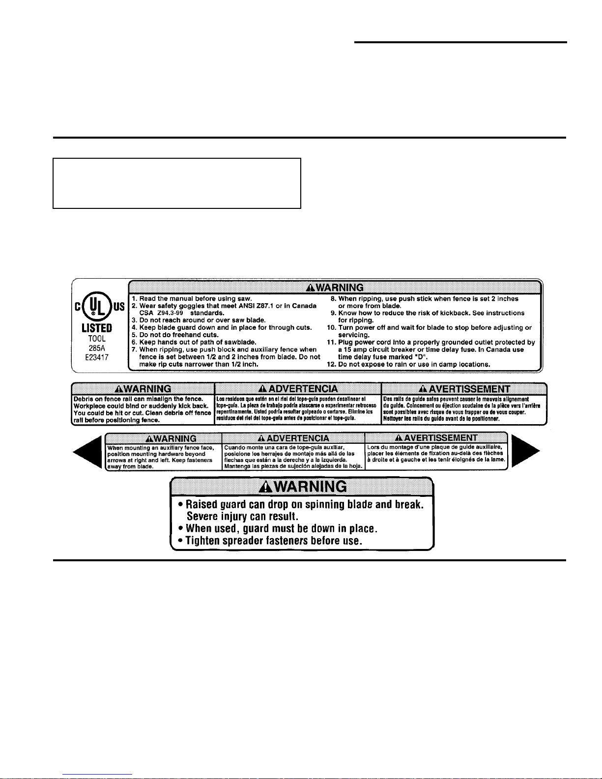
• Find and read all the warni ng labels found on t he saw
(shown below).
When Installing Or Moving The Saw
Reduce the Risk of Dangerous Environment.
• Use the saw in a dry, indoor place protected from rain.
• Keep work area well lighted.
• Use recommended accessories. Consult the owner’s
manual for recommended accessories. The use of
improper accessories ma y cause risk of in jury to persons.
To reduce the risk of injury from unexpected saw
movement.
• Bolt or clamp the saw to firm level surface where there is
plenty of room to handle and properly support the workpiece (See “Assembly-Mounting Your Sa w” secti on) .
• Support the saw so the table is level and the saw does
not rock.
• When using a table extension longer than 12" attached
to any side of the saw, bolt the saw to a stationary surface or prop up the outer end of the extension from the
floor or bench top to keep the saw from tipping.
• Put the saw where neither operator nor bystanders
must stand in line with the sawblade.
• To reduce the r is k of inj ury from electr ic al shock, make
sure your fingers do not touch th e plug’s metal prongs
when plugging in or unplugging the saw.
• Never Stand On Tool. Serious injury could occur if the
tool tips or you acciden tally hit the cutting to ol. Do not
store anything above or near the tool where anyone
might stand on the tool to reach them.
Page 4

4
Safety Instructions For Table Saw (continued)
Before Each Use
Inspect your saw.
• To reduce the risk of injury from accidental starting,
turn the switch off, unplug the saw, and remove the
switch key before raising or removing the guard,
changing the cutting tool, changing the setup, or
adjusting anything. Make sure switch is in OFF position
before plugging in.
• Check for alignment of moving par ts, binding of moving
parts, breaka ge of parts, saw stability, and any other
conditions that may affect the way the saw works.
• If any part is missing, bent or broken in any way, or any
electrical par t does not work pro perly, turn the saw off
and unplug the saw.
• Replace damaged or missing parts before using the
saw again.
• Use the sawblade guard, spreader and anti-kickback
pawls for any thru-sawing (whenever the blade comes
through the top of the wor kpiece). Make sure th e antikickback pawls work properly. Make sure the spreader
is in line with sawblade (See “Assembly-Aligning Blade
Guard” section).
• Remove adjusting keys and wrenches. Form a hab it o f
checking for and removing keys and adjusting
wrenches from table top before turning saw on.
• Make sure all clamps and locks are ti ght and n o par ts
have excessive play.
To Reduce the Risk of Injury From Jams, Slips Or Thro wn Pieces (Kickbac ks Or Throwbacks)
Inspect Your Blade.
• Choose the right blade or cutting accessory for the
material and the type of cutting you plan to do.
• Us e The Right Tool. Don’ t force tool or attachment to
do a job it was not designed for.
• Never use grinding wheels, abrasive cutoff wheels,
friction wheels (metal cutting blades) wire wheels or
buffing wheels. They can fly apart explosively.
• Cut only wood, wood like or pla stic materials. Do not
cut metal.
• Choose and inspect your cutting tool carefully:
- To reduce the r isk of cutting tool failure and thrown
shrapnel (broken pieces of blade), use only 10” or
smaller blades or other cutting tools marked for
speeds of 5000 rpm or higher.
- Always use un broken, balanced blades designed t o
fit this saw’s 5/8 inch arbor.
- When thru-sawing (making cuts where the blade
comes through the wor kpiece top), always use a 10
inch diameter blade. This keeps the spreader closest
to the blade.
- Do not over tighten arb or nut. Us e ar bor wr en ch es t o
“snug” it securely.
- Use on ly sharp blades with pro perly set teeth. Consult a professional blade sharpener when in doubt.
- Keep blades clean of gum and resin.
- Never use the saw without the proper blade insert.
Inspect your work area.
• Keep work area clean.
• Cluttered areas and benches invite accidents. Floor
must not be slippery from wax or sawdust.
• To reduce the r is k of bur ns or othe r fi re dam age, never
use the saw near flammable liquids, vapors or gases.
• To reduce the risk of i njury, don’t do layout, assembly,
or setup work on the table while blade is spi nning. It
could cut or throw anything hitting the blade.
Plan your work
• Use the right tool. Don’t force tool or attachment to do
a job it was not designed for.
Inspect your workpiece.
• Make sure there are no nail s or foreign objects in th e
part of the workpiece to be cut.
• When cutting irreg ular ly shape d wor kpie ces, plan your
work so it will not slip and pinch the blade:
• A piece of molding for example, must lie flat o r be hel d
by a fixture or jig that will not let it twist, rock or slip
while being cut. Us e jigs or fixtures where ne eded to
prevent workpiece from shifting.
• Use a different, better suited type of tool for work that
can’t be made stable.
Plan your cut.
• To reduce the ris k of kickbacks and throwbacks - when
a part o r all of the wor k pi ece b ind s on the blade and is
thrown violently back toward the front of the saw:
-Never cut Freehand. Always use either a rip fence,
miter gauge or fixtur e t o po si tio n a nd gui de the wor k ,
so it won’t twist or bind on the blade and kick back.
- Make sure th ere’s no debris between the workpiec e
and its supports.
• Use extra caution with large, very small or awkward
workpieces.
• Use extra supports (tables, saw horses, blocks, etc.)
for any workpieces large enough to tip when not held
down to the table top. Never use another person as a
substitute for a table extension, or as additional support for a workpiece that is longer or wider than the
basic saw table, or to help feed, support or pull the
workpiece.
• Never confine the piece being cut off, that is, the piece
not against the r ip fence, miter gauge or fixture. Never
hold it, clamp it, touch i t, or use l en gth s to ps agai ns t i t.
It must be free to move. If confined, it could get
wedged against the blade and cause a kickback or
throwback.
• Never cut more than one workpiece at a time.
• Never turn your table saw “ON” before clearing everything except the workpiece and related support
devices o ff the table.
Page 5
5
Plan Ahead To Protect Your Eyes, Hands, Face and Ears
Dress for safety
• Do not wear loose clothing, gloves, neckties or jewelry
(rings, wrist watch es). They can get caught and draw
you into moving parts.
• Wear nonslip footwear.
• Tie back long hair.
• Roll long sleeves above the elbow.
• Noise levels vary widely. To red uce the r i sk of poss ible
hearing damage, wear ea r plugs or muffs when using
table saw for hours at a time.
• Any power saw can throw foreign objects into the eyes.
This can result in permanent eye damage. Always
wear safety goggles, not glasses complyi ng with ANS I
Z87.1 (or in Canada CSA Z94.3-99) shown on package. Everyday eyeglasses have only impact resist ant
lenses. They are not safety glasses. Safety goggles
are available at many local retail stores. Glasses or
goggles not in compliance with ANSI or CSA could
seriously hurt you when they break.
• For dusty operations, wear a dust mask along with
safety goggles.
Plan the way you will push the workpiece through.
• Never pull the workpiece through. Start and finish
the cut from the front of the table saw.
• Never put your fingers or hands in the path of the
sawblade or other cutting tool.
• Never reach in back of the cutting tool with either
hand to hold down workpiece, supp ort the workpiec e,
remove wood scraps, or for any other reason.
• reduce the risk of hand positio ns where a su dden slip
could cause fingers or hand to move into a sawblade
or other cutting tool.
• Don’t overreach. Alw ays keep good footing an d b ala nce.
• Push the workpiece a gainst the rotation of the blade,
never f eed material into the cutting tool from the rear of
the saw.
• Always push the workpiece all the way past the sawblade.
• As much as possible, keep your face and body to one
side of the sawblade, out of line with a possible kickback or throwback.
• Set the cutting tool as low as possible for the cut you’re
planning.
Reduce the Risk of Accidental Starting.
• Make sure switch is “OFF” before plugging saw into a
power outlet.
Whenever Sawblade Is Spinning
WARNING: Don’t allow familiarity (gained from frequent use of your table saw) to cause a careless
mistake. Always remember that a carele ss f r action
of a second is enough to cause a severe injury.
• Before actually cutting with the saw, watch it while it
runs for a short while. If it makes an unfamiliar noise or
vibrates a lot, stop immediately. Turn the saw off.
Unplug the saw. Do not restart until finding and correcting the problem.
• Make sure the top of the arbor or cutting tool turns
toward the front of the saw.
Keep Children Away.
• Keep all visitors a safe distance from the table saw.
• Make sure bystanders are clear o f the table saw and
workpiece.
Don’t Force Tool.
• Let the blade reach full speed before cutting.
• It will do the job better and safer at its designed rate.
• Feed the workpiece into the saw only fast enough to let
the blade cut without bogging down or binding.
Before freeing jammed material.
• Turn switch “OFF”.
• Wait for all moving parts to stop.
• Unplug the saw.
• Check blade, spreader and fence for proper alignment
before starting again.
To reduce the risk of throwback of cut off pieces.
• Use the guard assembly.
To remove loose pieces beneath or trapped inside
the guard.
• Turn saw “OFF”.
•Remove switch key.
• Wait for blade to stop before lifting the guard.
Before Leaving The Saw.
• Turn the saw off.
• Wait for blade to stop spinning.
• Unplug the saw.
• Make workshop child-proof. Lock the shop. Disconnect
master switches. Remove the yellow switch key. Stor e
it away from children and others not qualified to use
the tool.
Page 6
6
Safety Instructions For Table Saws (continued)
Additional Safety Instructions For:
Rip Type Cuts.
• Never use the miter gauge when ripping.
• Use a push stick whenever the fence is 2 inches or
more from the blade.
• When thru-sawing, use an auxiliary fence and push
block whenever the fence must be between 1/2 and 2
inches from the blade.
• Never thru-saw rip cuts narrower than 1/2 inch. (See
“Basic Saw Operations-Ripping and Bevel Ripping”
sections.)
• Never rip anything shorter than 10” long.
• When using a push stick or push block, the trailing end
of the board must be square. A push stick or block
against an uneven end could slip off or push the work
away from the fence.
• A Featherboard can help guide the workpiece. (see
”Basic Saw Operation-Using Featherboards for ThruSawing.” section)
• Always use featherboards for any non thru rip type cuts.
(See “Basic Saw Operatio ns - Using Featherboards for
Non-Thru Sawing” section)
Before Starting.
• To reduce the risk of kickbacks and slips into the blade,
make sure the rip fence is parallel to the sawblade.
• Before thru-sa wi ng, chec k the an ti-k ic k bac k p a wls . The
pawls must stop a kickback once it has started.
Replace or sharpen anti-kickback pawls when points
become dull. (See “Maintain ing Your Table Saw - AntiKickback Pawls” section.)
• Plastic and composition (like hardboard) materials may
be cut on your saw. However, since these are usually
quite hard and slippery, the anti-kickback pawls may
not stop a ki ckback. Therefore, be espe ci al ly car ef ul i n
your setup and cutting procedures.
While Thru-sawing.
• To reduce the risk of kickbacks and slips into the blade,
always push forward on the section of the workpiec e
between the sawblade and the rip fence. Never push
forward on the piece being cut off.
Additional Safety Instructions For:
Crosscut Type Cuts.
• Never use the rip fence when crosscutting.
• An auxiliar y wood facing attached to th e miter gauge
can help prevent workpiece twisting and throwbacks.
Attach it to the slots provided. Make the facing long
enough and big enough to suppor t your work. Make
sure, however, it will not interfere with the sawblade
guard.
Before Starting.
• Use jigs or fixtures to help hold any piec e too small to
extend across the full length of the miter gauge face
during the cut. This lets you properly hold the miter
gauge and workpiece and helps keep your hands away
from the blade.
While Cutting
• To reduce the risk of blade contact, always hold the
miter gauge as shown in “Basic Saw Operations Using The Miter Gauge”.
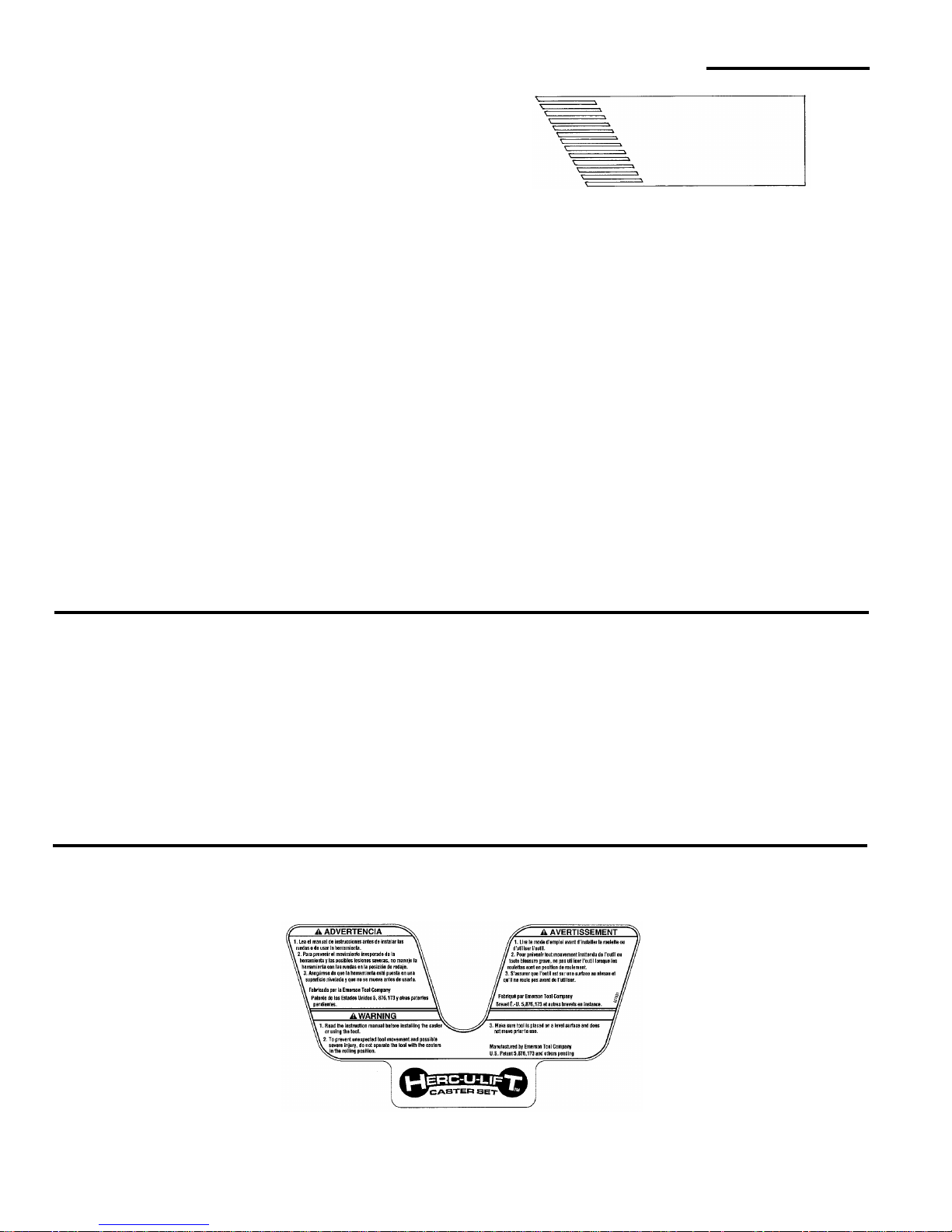
Additional Safety Instructions For Herc-U-Lift™ Caster System:
Before Using the Caster System
Read the following warning located on the plate assembly:
To reduce the risk of injury from unexpected tool
movement.
• Check to make sure tool does not move prior to use. If
tool mov es , adju st al l f our leveler feet to suppo rt the tool .
• Put the tool on a firm level surface where there is plenty
of room to handle and pr o perly support the workpi ec e.
Featherboard
See “Work Feed Devices” section for
Material and Dimensions
Page 7
7
Glossary of Terms for Woodworking
Anti-Kickback Pawls
Device which, when proper ly maintained, is de signed to
stop the workpiece from being thrown towards the front of
the saw at the operator during ripping operation.
Arbor
The shaft on which a cutting tool is mounted.
Bevel Cut
An angle cutting operation made thr ough the face of the
workpiece.
Compound Cut
A simultaneous bevel and miter crosscutting operation.
Crosscut
A cutting operation made across the width of the work piece.
Dado
A non thru cut which produc es a square sided notch or
trough in the workpiece.
Featherboard
A device which can help guide workpieces during rip type
operation.
Freehand
Performing a cu t without the use of fence (guide), miter
gauge, fixture, hold down or ot her proper device to prevent the workpiece from twisting during the cutting operation. Twisting of the workpiece can cause it to be thrown.
Gum
A sticky, sap based residue from wood products.
Heel
Misalignment of the sawblade such that the blade is not
parallel to the miter gauge groove.
Kerf
The amount of material removed by the blade in a
through cut or the slot produced by the blade in a no nthrough or partial cut.
Kickback
An uncontrolled grabbing and throwing o f the workpiece
back toward the front of the saw.
Leading End
The end of the workpiec e whic h, dur ing a r ip type op eration, is pushed into the cutting tool first.
Miter Cut
An angle cutting o peration made a cross the width o f the
workpiece.
Molding
A non through c ut wh ic h produces a special sh ape in the
workpiece used for joining or decoration.
Ploughing
Grooving with the grain the length of the workpiece, using
the fence. (A type of non-through cut)
Push Stick
A device used to feed the workpiece through the saw during narrow ripping type operations which he lps keep the
operator’s hands well away from the blade.
Push Block
A device used for ripping type operations too n arrow to
allow use of a push stick.
Rabbet
A notch in the edge of a workpiece. (A type of nonthrough cut)
Resin
A sticky, sap based substance that has hardened.
Revolutions Per Minute (RPM)
The number of turns co mpleted by a spinning object in
one minute.
Rip Cut
A cutting operation along the length of the workpiece.
Sawblade Path
The area of the workpiece or table top directly in line with
either the travel of the blade or the part of the workpiec e
which will be, or has been, cut by the blade.
Set
The distance that the tip of the sawblade tooth is bent ( or
set) outward from the face of the blade.
Throw-Back
Throwing of pieces in a manner similar to a kickback.
Thru-Sawing
Any cutting operation where the blade extends completely through the thickness of the workpiece.
Trailing End
The workpiece end last cut by the blade in a ripping operation.
Workpiece
The item on which the cutting operation is being performed. The surfaces of a workpiece are commonly
referred to as faces, ends, and edges.
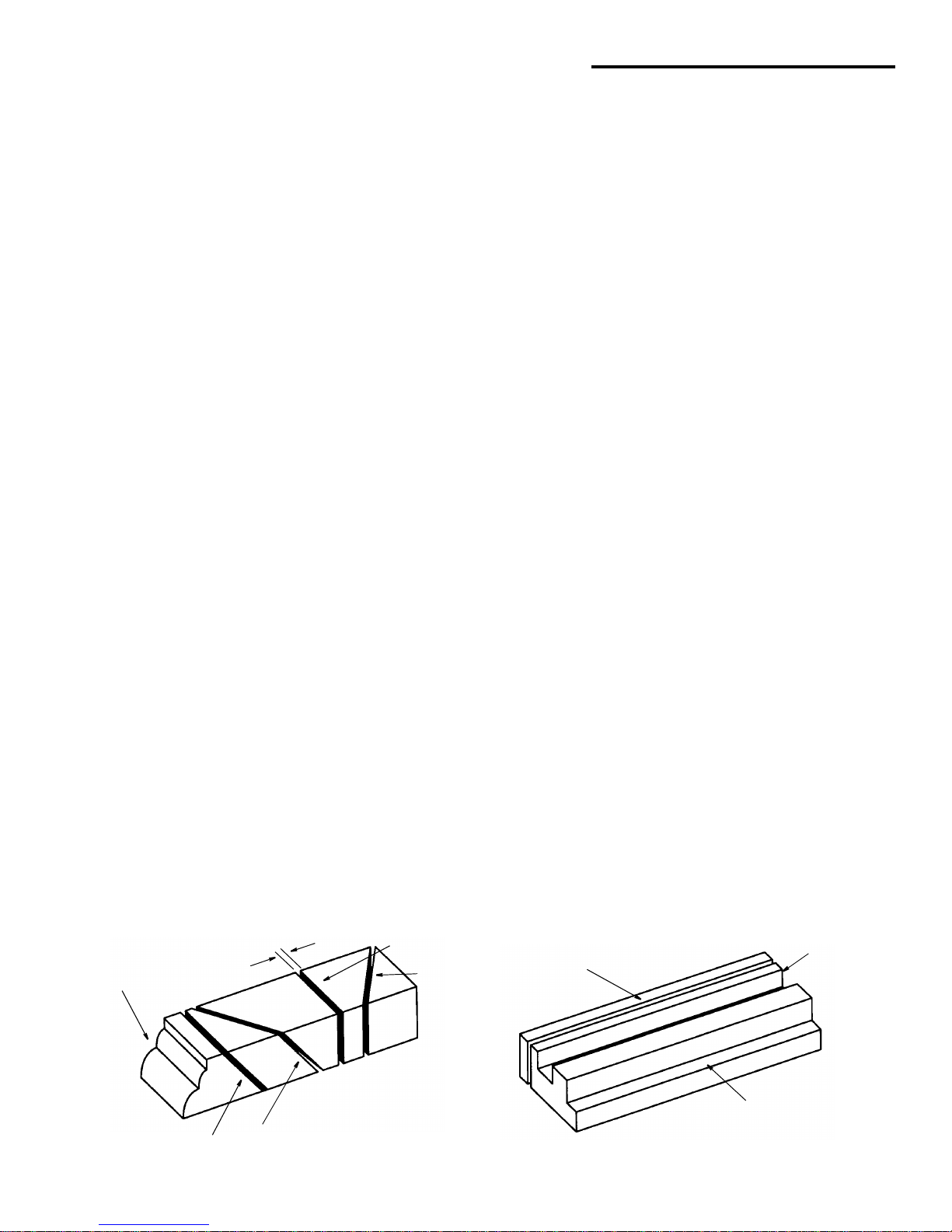
Molding
Kerf
Cross Cut
Miter Cut
Compound Cut
Bevel Cut
Rip Cut
Dado or
Rabbet
Ploughing
Page 8
8
Motor Specifications and Electrical Requirements
Power Supply and Motor Specifications
WARNING: To reduce the risk of electrical hazards,
fire hazards or damage to the tool, use proper circuit protection. Your tool is wired at the factory for
operation using the voltage shown. Connect tool
to a power line with the appropriate voltage and a
15-amp branch circuit. Use a 15-amp time delay
type fuse or circuit breaker. To reduce the risk of
shock or fire, if power cord is worn or cut, or damaged in any way, have it replaced immediately.
The A-C motor used on this tool is a cap acit or sta rt, capacitor run non-reversible type, having the following specifications. It is wired at the factory for operat ion on 110- 120v AC,
60 Hz. service.
General Electrical Connections
DANGER: To reduce the risk of electrocution:
1. Use only identical replacement parts w hen servicing. Servicing should be performed by a
qualified service technician.
2. Do not use in rain or where floor is wet.
This tool is intended for indoor residential use
only.
WARNING: Do not permit fingers to touch the terminals of plug when installing or removing the
plug to or from the outlet.
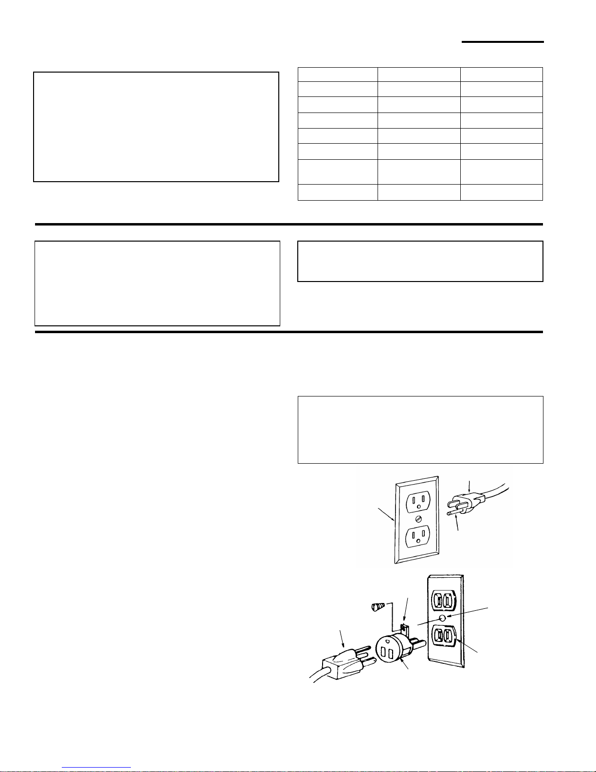
110-120 Volt, 60 Hz. Tool Information
The plug supplied on your tool may not fit into the outlet
you are planning to use. You r local electrical code may
require slightly different power cord pl ug connections. If
these differences exist refer to and make the proper
adjustments per your local code before your tool is
plugged in and turned on.
In the event of a malfunction or breakdown, grounding
provides a path of le ast resistance for electric curren t to
reduce the risk of electric shock. This tool is equipped
with an electric cord having an equipment-grounding conductor and a grounding plug, as shown. The plug must be
plugged into a mat ching outlet that is properly installed
and grounded in accordance with all local codes and
ordinances.
Do not modify the plug pr ovide d. I f it wi ll not fit the ou tle t ,
have the proper outlet installed by a qualified electrician.
A temporary ada pte r may be used to co nne ct t his pl ug t o
a 2-prong outlet as shown if a pro perly grounded three
prong outlet is not available. This temporary adapter
should be used only until a properly grounded three
prong outlet can be installed by a qualified electrician.
The green colored rigid ear, lug or the like, extending
from the adapter must be connected to a permanent
ground such as a properly grounded outlet box.
Improper connection of the equipment-grounding conductor can result in a r isk of electric s hock. The conductor with insulation having an outer surface that is green
with or without yellow stri pes i s the equ ipm ent-ground ing
conductor. If repair or replacem ent of the electr ic cord or
plug is necessary, do not connect the eq uip men t- groun ding conductor to a live terminal.
If the grounding instructions are not completely understood, or if you are in doubt as to whether the tool is properly grounded check with a qualified electrician or service
personnel.
WARNING: If not properly grounded, this tool can
cause an electrical shock, particularly when used
in damp locations, in proximity to plumbing, or out
of doors. If an electrical shock occurs there is the
potential of a secondary hazard, such as your
hands contacting the sawblade.
NOTE: The adapter illustrated is for use only if you
already have a properly grounded 2-prong outlet.
NOTE: In Canada the use of a temporar y adapter is not
permitted by the Canadian Electrical Code.
Wired for 120V Wired for 240V
Rated H.P
1-1/2 1-1/2
Voltage 110-120 220-240
Amperes 13 6.5
Hertz (Cycles) 60 50/60
Phase Single Single
RPM 3450 2875 (50 Hz)/
3450 (60 Hz)
Rotation of Shaft
Clockwise Clockwise
3-Prong
Adapter
2-Prong
Outlet
Make sure this
Is Connected
Ground
Plug
to a Known
Grounding Lug
Properly
Grounded
3-Prong Plug
Grounding
Prong
3-Prong Outlet
Page 9
9
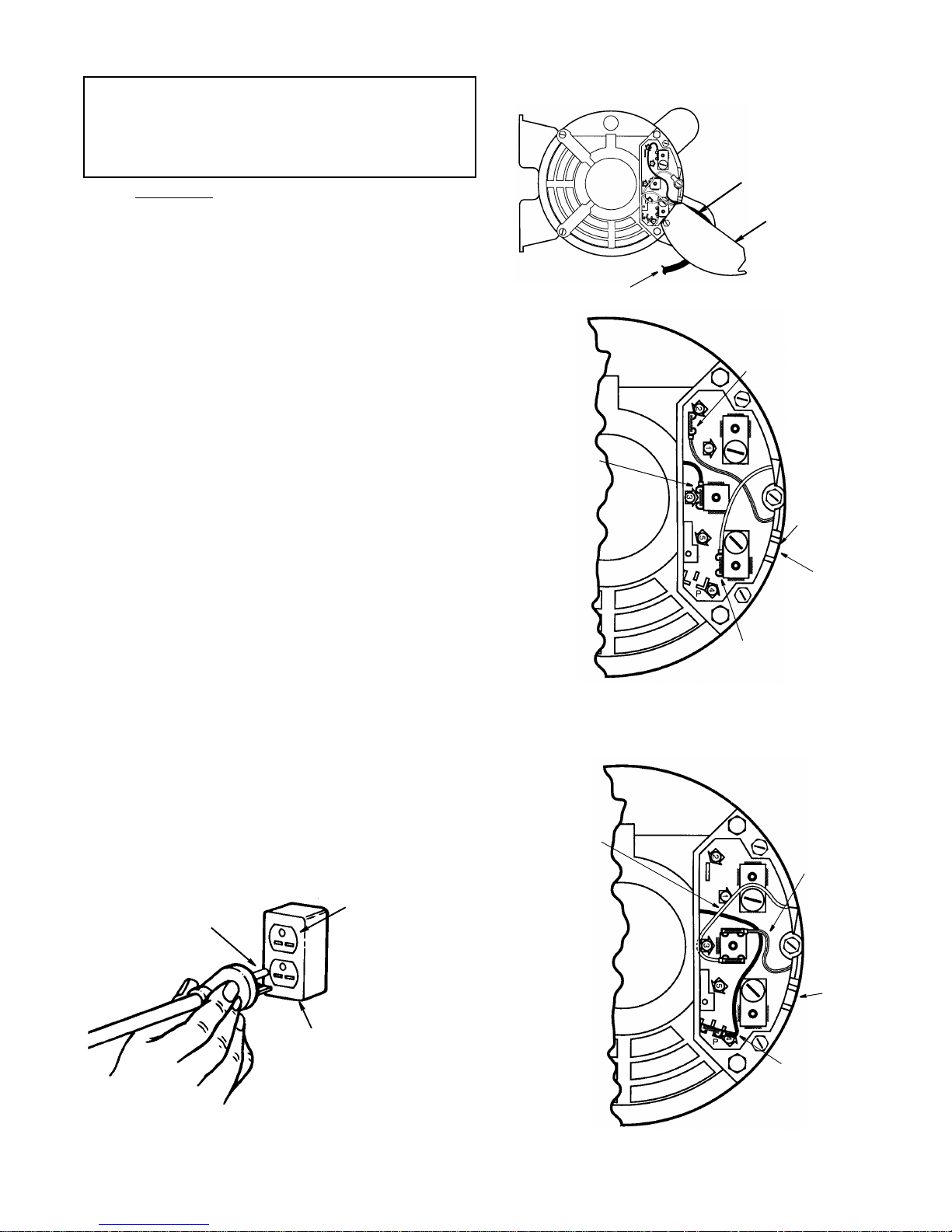
Changing Motor Voltage
WARNING: Electric shock can kill. To reduce the
risk of shock, never connect plug to power source
outlet until all assembly steps are completed.
Unplug saw before making or changing any connections.
NOTE: Power cord
lead connections for 110/120 volt and
220/240 volt applications are the same. This will show
how to change the interna l motor wiring to convert saw
from a 120V to a 240V application.
1. Open the motor connector box cover located on the
end of motor using a flat blade screwdriver to loosen
screws.
2. From the factory this motor is connected for 120V
usage. For 240V usage:
a. Remove the brown motor lead from termi nal #3 and
attach it to the “P” (parking position) plastic terminal.
NOTE: This brown lead is not require d for the 240
volt application and is “pa rked” in the pl astic “P” ter minal to keep it insulate d. Be sur e the b rown lead is
attached securely to the “P” terminal holder.
b. Remove the yellow motor lead from ter minal #4 an d
attach it to terminal #3.
c. Remove the red motor lead from terminal #2 and
attach it to terminal #3.
d. Cut off the 120 volt power cord plug and replac e it
with a (3 blade) 240 volt 15 amp U.L. listed plug.
(See illustration of 240V plug & receptacle.) Connect
the power cord white and black leads, respectively,
to the “hot” plug blade terminals and connect the
power cord green grounding wire to the plug ground
prong terminal.
3. Close motor conn ector box being sure that the p ower
cord is seated in the strain relief groove and tighten
box cover screws.
4. Plug your saw into a 220 -2 40V, 15amp, 3 blade recep-
tacle.
5. Make certain the receptacle is connected to a 240V
A.C. power supply through a 240V branch circuit having at least a 15 amp capacity and prote cted by a 15
amp time-delay fuse or circuit breaker.
Grounding
Prong
Grounded
Outlet Box
220-240V
15 Amp 3 Blade
Receptacle
Connector
Box Cover
Yellow Motor
Lead on
Terminal #3
220/240 Volt Connection
Brown Motor
Lead On
Terminal “P”
(Plastic)
Strain
Relief
Groove
Red Motor
Lead on
Terminal #3
Lead On
110/120 Volt Connection
Red Motor Lead
On Terminal #2
Brown Motor
Terminal #3
Yellow Motor Lead
On Terminal #4
Strain
Relief
Groove
Power Cord
To Switch Box
(As Received From Factory)
NOTE: Power
Cord Not
Shown For
Clarity
Cord Exit/
Cord Exit/
Page 10
10
Motor Specifications and Electrical Requirements (continued)
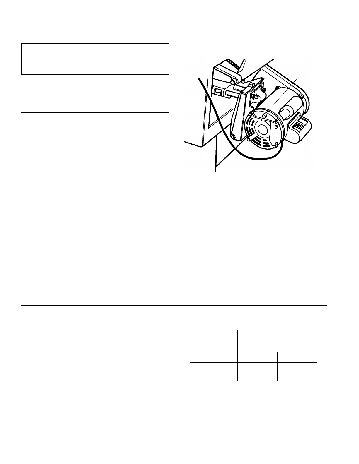
Motor Thermal Overload Protector
CAUTION: To reduce the risk of motor damage,
this motor should be blown out or vacuumed frequently to prevent sawdust buildup which will
interfere with normal motor ventilation.
Your saw is equipped with a manual-reset ther mal-overload protector designed to open the power line circuit
when the motor temperature exceeds a safe level, when
motor is overloaded or when a low voltage condition
exists.
WARNING: To reduce the risk of thrown objects or
blade contact from unexpected starting. If the protector stops the saw motor, immediately turn the
saw switch “OFF”, remove the key and allow motor
time to cool.
1. After cooling to a safe operating temperature, the overload protector can be res et by pushing the red button
on the end of the motor. If the red button will not click
into place immediately, the motor is still too hot and
must be allowed to cool for a while longer.
The time required for the motor to cool may be equal to
the length of time the saw was used before the thermal
overload protector opened. NOTE: An audible click will
indicate the protector is reset, push hard to hear the
click.
2. As soon as the red button is reset, the saw may be
started and operated normally.
3. Frequent “blowing” of fuses or tripping of circui t break-
ers may result if:
a. Motor is overloade d - Overloading can occur i f you
feed too rapidly or if saw is misaligned.
b. Motor circu it is fused differently from recomm enda-
tions - Always follow instructions for the proper fuse/
breaker. Do not use a fuse/breaker of greater capacity without consulting a qualified electrician.
c. Low voltage - Although the motor is designed for
operation on the voltage and frequency s pecif ied on
motor nameplate, normal loads will be handled
safely on voltage not more than 10% above or below
the nameplate voltage. Heavy loads, however,
require that voltage at motor terminals equals the
voltage specified on nameplate.
4. Most motor t roubles may be traced to loose or incorrect connections, overloading, reduced input voltage
(such as small size wire in the supply circuit) or to
overly long supply circuit wir e. Always check the connections, the load and the supply circuit whenever
motor fails to perform satisfactorily. Check wire sizes
and length with the Wire Size Chart below.
Wire Sizes
NOTE: Make sure the proper extension cord is used and
is in good condition.
The use of any extension cord will cause some loss of
power. To keep this to a minimum and to prevent overheating and motor burn-out, use the table shown to
determine the minimum wire size (A.W.G.) extension
cord.
Use only 3-wire extension cords which have 3-prong
grounding type plugs and 3-prong receptacles which
accept the tool’s plug.
Manual
Reset
Button
Extension
Cord Length
Gauge
(A.W.G.)
110-120V 220-240V
0-25 Ft.
26-50 Ft.
14
12
18
18
Page 11
11
Unpacking and Checking Contents
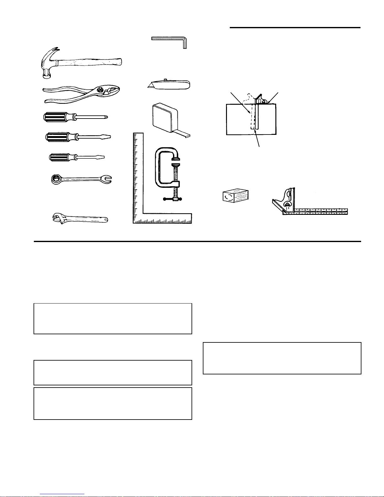
Tools Needed
Unpacking
1. Separate saw and all parts from packing materials and
check each one with the illustration and the “List of
Loose Parts” to make certain all it ems are accounted
for, before discarding any packing material. Call 1-8004-RIDGID or E-mail us at info@ridgidwoodworking.com if any parts are damaged or missing.
WARNING: If any parts are missing, do not attempt
to assemble the table saw, plug in the power cord
or turn the switch on until the missing parts are
obtained and are installed correctly.
2. Remove the protective oil that is applied to the table
top and edges of the table and table extensions. Use
any ordinary household type grease and spot remover.
WARNING: To reduce the risk of fire or health hazard, never use gasoline, naptha, or similar highly
volatile solvents.
WARNING: The saw is heavy. To reduce the risk of
back injury, ge t help to lift the saw. Hold the saw
close to your body. Bend your knees so you can lift
with your legs, not your back .
3. Apply coat of paste wax to the table and table extensions.
NOTE: Before beginning assembly:
• Check that all parts are included. If you are missing any
part, do not assemble the saw.
• So metime s small parts can get los t in packaging ma terial. Do not throw away any packaging until saw is put
together. Check packaging for missing parts before
contacting RIDGID.
• A complet e par ts list (R epair Parts ) is at t he end of the
manual. Use this list to identify the par t number of the
missing part.
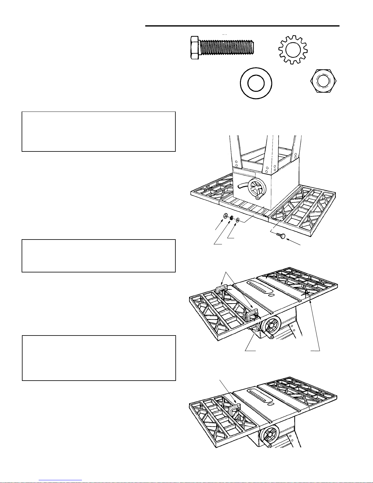
NOTE: At the beginning of each as sembly section it ems
such as nuts and bolts are shown actual size.
WARNING: For your own safety, never connect
plug to power source outlet until all assembly
steps are complete, and you have read and understand the safety and operating instructions.
Combination Square must be true. Check it’s
accuracy as shown below.
Draw light line on
Should be no gap or overlap here when square
is flipped over in dotted position.
Phillips Screwdriver
Medium Screwdriver
Small Screwdriver
Hex “L” Wrenches
Pliers
Combination
Square
Tape Rule
3/32 In., 2.5mm,
Combination Wrenches
7/16 In., 1/2 In., 9/16 In.,
board along edge
Utility Knife
C Clamp
Framing Square
Select the straight edge of
NOTE: The square and
straight edge are used to
3/4” thick board. This edge
must be perfectly straight.
align the saw. They must
be accurate if the saw is
to be aligned properly.
Hammer
Adjustable Wrench
Wood Blocks
1/8 In., 5/32 In., 3/16 In.
3/4 In., 11/16 In.
3/4" Thick (Optional)
Page 12
12
Unpacking and Checking Contents (continued)
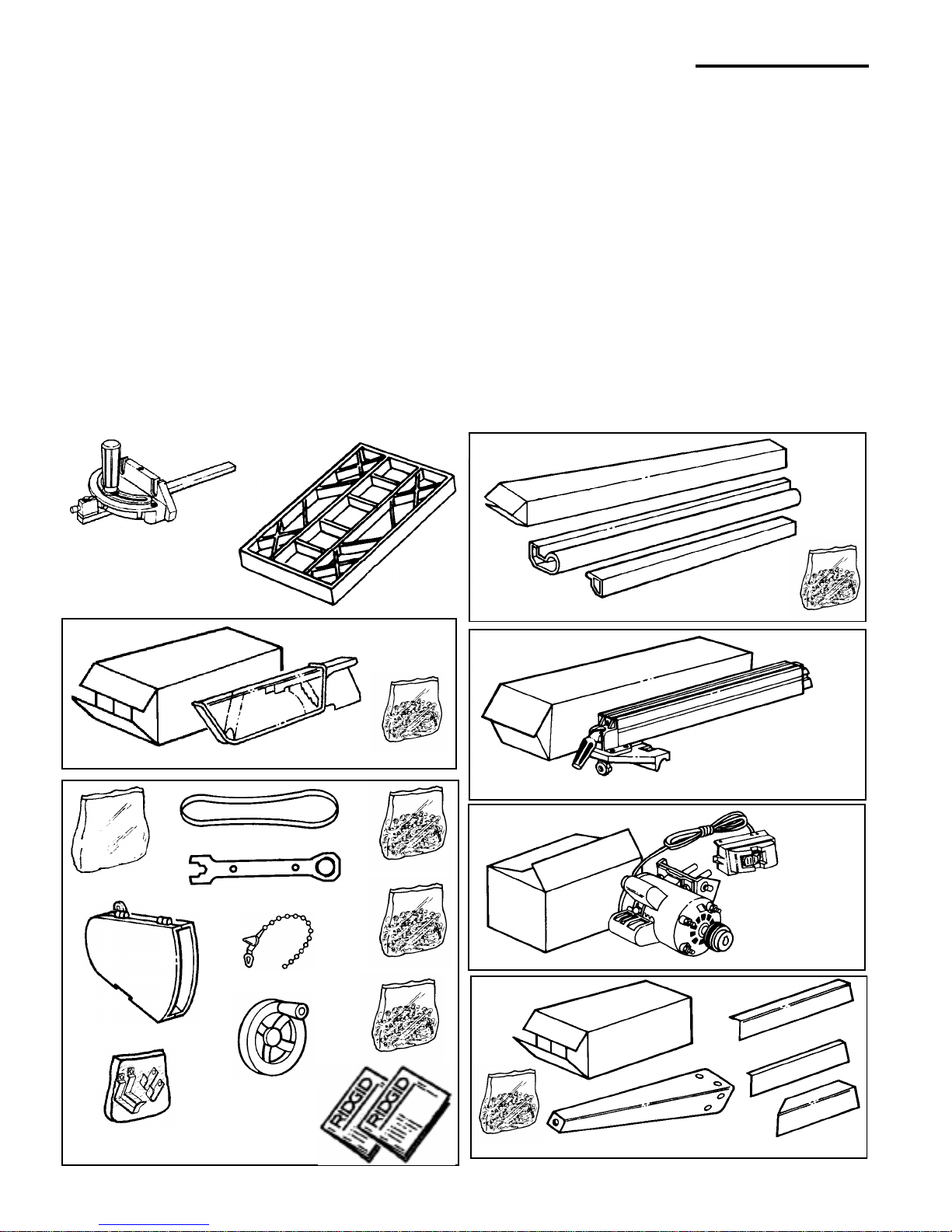
List of Loose Parts
Item Part Name Qty.
A Miter Gauge..........................................................1
B Table Extension ................................... ...... ....... ....2
Blade Guard Carton Containing:
C Blade Guard.........................................................1
D Blade Guard Parts Bag ........................................1
Large Parts Bag Containing:
E Belt Guard ............................................................1
F Storage Hook Bag................................................1
G Drive Belt..............................................................1
H Blade Wrench.......................................................1
J Wire Tie ................................................................2
K Handwheel ...........................................................2
L Trim Parts Bag......................................................1
M Table Extension Parts Bag ...................................1
N Miscel la neou s Parts Bag..................... ...... ....... ....1
P Owners Manual (English) .....................................1
Q Owners Manual (Spanish)....................................1
Item Part Name Qty.
Fence Guide Bar Carton Containing:
R Front Fence Guide Bar.........................................1
S Rear Fence Guide Bar .............................. ....... .... 1
T Guide Bar Parts Bag ............................................1
Rip Fence Carton Containing:
U Rip Fence.............................................................1
Motor Carton Containing:
V Motor/Switch Assembly........................................1
Leg Stand Carton Containing:
W Leg .......................................................................4
X Leg Brace (Short).................................................2
Y Side Stringer ........................................................2
Z End Stringer .........................................................2
AA Leg Stand Parts Bag ............................................1
Blade Guard Carton
Large Parts Bag
Motor Carton
Rip Fence Carton
Fence Guide Bar Carton (Service #509469)
T
U
V
W
X
Y
Z
D
C
E
S
Leg Stand Carton
A
B
F
G
J
P
L
M
N
H
Q
K
AA
R
Page 13
13
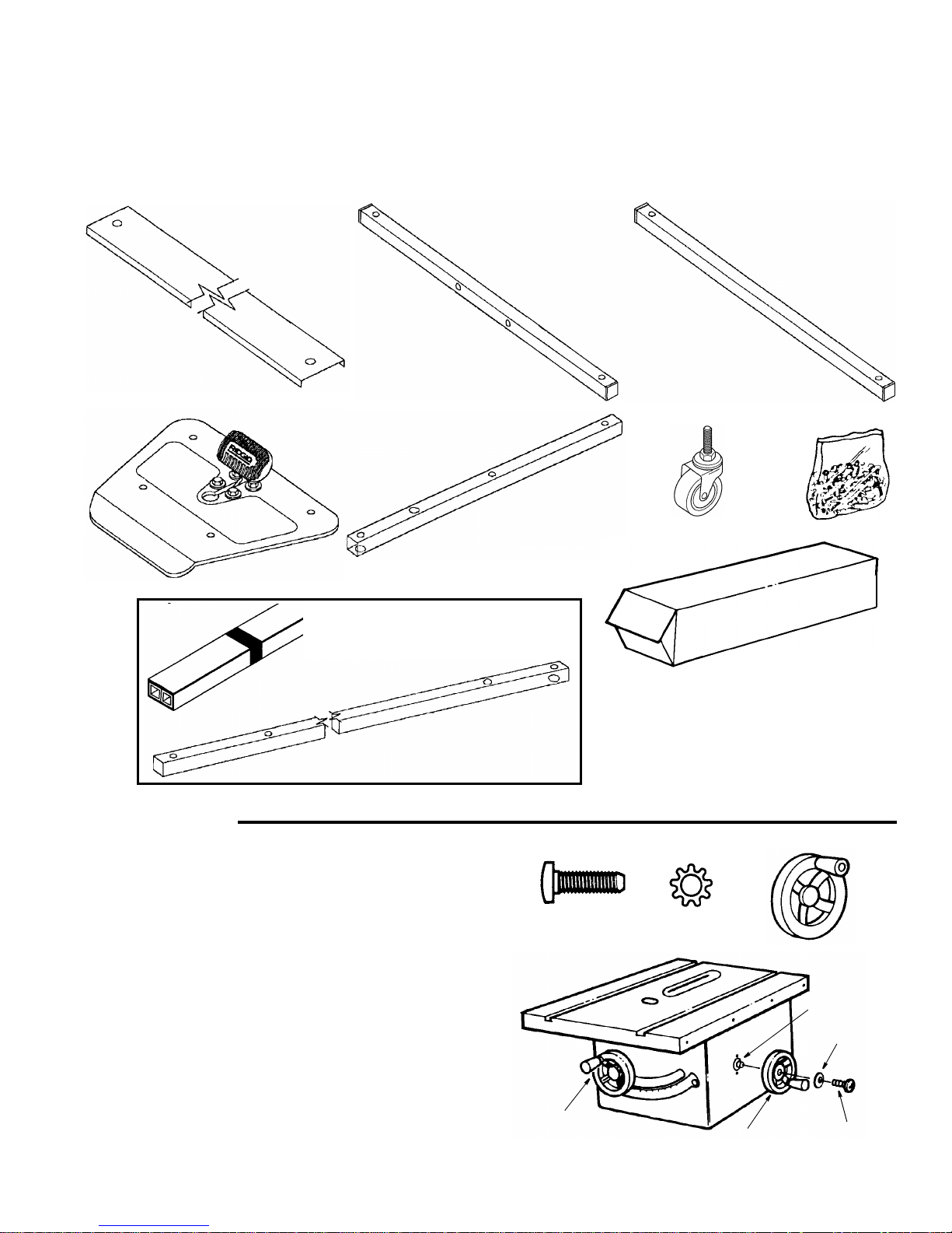
Herc-U-Lift™ Caster Carton
Item Description Qty.
A Channel Rear ...................................................... 1
B Tube U-Bolt 19-5/8" Long..................................... 1
C Tube Support 17-1/4" Long.................................. 1
D Plate Assembly .................................................... 1
Item Description Qty.
E Tube Front 13-7/8" Long .......................................2
F Caster Swivel 3"....................................................4
G Tube Rear 27" Long..............................................2
H Bag Loose Parts ...................................................1
Loose Parts
Assembly
Installing Handwheels
1. From the bag labeled “Misc el laneous” remove only the
following hardware:
2 Pan Head Screws, 10 - 32 x 5/8" long
2 Lockwashers, #10 External Type
From among the loose parts find the following:
2 Handwheels
2. Line up flat spots on shaft and handwheel, push
handwheel onto sh aft. Insta ll screw and lockwasher to
lock handwheel on shaft. Repeat for the other handwheel.
H
A
B
C
D
E
G
F
Item G packed separately in
main table saw box
Pan Head Screw
10-32 x 5/8
#10 External
Lockwasher
Shaft
Pan Head
Bevel
Handwheel
Elevation
Handwheel
Lockwasher
Screw
Handwheel
Page 14
14
Assembly (c ontinued)
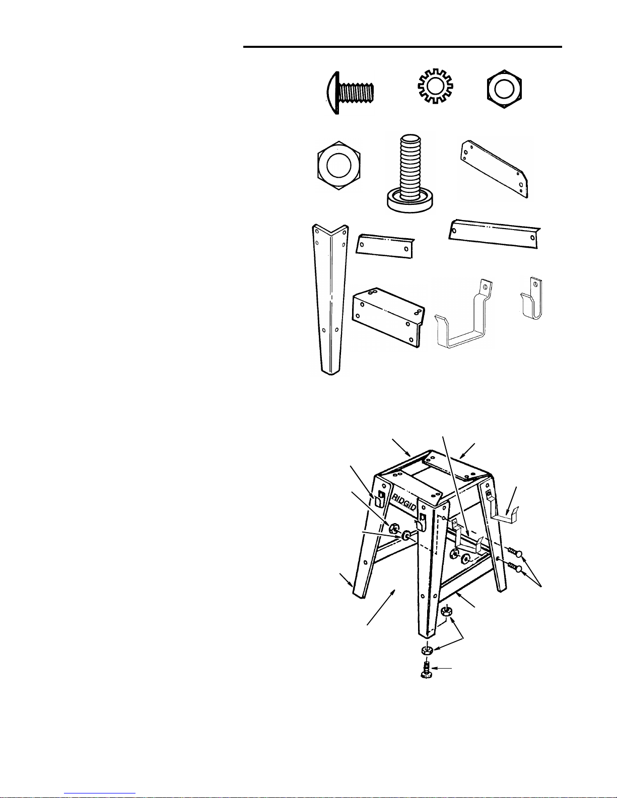
Assembling Leg Stand
1. Locate the carton containing the leg stand.
Remove all parts from packing material.
2. From the bag labeled “Legs” remove the following
hardware:
22 Truss Head Screws, 1/4-20 x 1/2” long
22 Lockwashers, 1/4” External Type
22 Hex Nuts, 1/4-20
4 Leveling Feet
8 3/8-16 Hex Nut
From leg stand carton find the following:
4 Legs
2 End Stringers
2 Side Stringers
3 Leg Braces (Two Long, One Short)
3. From among the loose parts find the following:
2 Miter Gauge Storage Hooks
2 Rip Fence Storage Hooks
4. Assemble the legs as shown.
Insert the tr uss head screws through the holes in the
legs, then through the holes in the side and end
stringers. Attach miter gauge and rip fence storage
hooks as shown.
Legs must be assembled on top of stringers
5. Install the lockwashers. Screw on the nuts hand tight.
6. Insert the tr uss head screws through the hol es in the
legs, then through the holes in the leg braces. Plac e
short leg b race on opposite side of RIDGID logo as
shown.
7. Install the lockwashers. Screw on the nuts but do not
tighten until completely assembled.
8. Install leveling feet through holes in bottom of legs as
shown. Adjust feet all the way up to bottom of leg.
9. Once you have completed the entire assem bly pro-
cess, move saw to desired location and adjust the
four leveling feet to support the tool as follows:
a. With 9/16" wrench loosen bottom nut.
b. Back off top nut by hand.
c. Raise or lower foot by adjusting bottom nut using
9/16" wrench.
d. Snug top nut against ins id e of leg by hand.
e. Tighten all four bottom nuts using 9/16" wrench.
1/4-20 x 1/2 In.
T
russ Head Screw
1/4 In. External
Lockwasher
1/4-20
Hex Nut
Leg
Stringers
End
Stringer
Side
Leg Brace
Miter Gauge
Storage Hooks
Rip Fence
Storage Hooks
(Short)
3/8 -16 Hex Nut
Leveling Foot
(Long)
Leg Braces
Lockwasher
1/4-20
Hex Nut
T russ Head
Screw
Legs
End Stringers
Side Stringers
Leg Brace
Herc-U-Lift™ Caster
System Will Be
Installed Here
Leg Brace
(Long)
(Short)
Leveling Foot
3/8-16 Hex Nuts
Rip Fence
Storage Hook
Miter Gauge
Storage Hook
Page 15
15
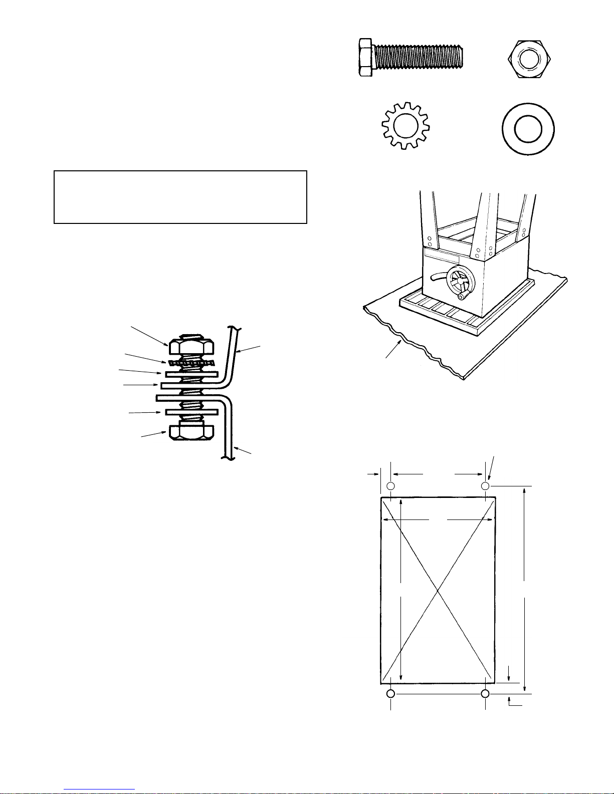
Mounting Your Saw
1. From the bag labeled “Legs” remove the following
hardware:
4 Hex Head Screws, 5/16-18 x 1-1/4" Long
4 Hex Nuts, 5/16-18
4 Lockwashers, 5/16" External Type
8 Flat Washers, 11/32 x 11/16 x 1/16
2. Place the saw upside down onto a smooth piece of
cardboard or heavy paper, on the floor, so the saw is
resting on the table top.
WARNING: The saw is heavy. To reduce the risk of
back injury, ge t help to lift the saw. Hold the saw
close to your body. Bend your knees so you can lift
with your legs, not your back .
3. Place legs on saw so that holes in saw base and le g
set line up and trim label is facing front.
4. Install screw, washers, lockwasher and nut as shown.
5. Tighten all leg assembly and mounting hardware at
this time.
Bench Mounting
If you do not use the legset and mount the saw on a
bench, make sure that there i s an opening in the top of
the bench the same size as the openin g in the bot tom of
the saw so that the sawdust can drop through. Recommended working height is 33 to 37 inches from the top of
the saw table to the floor.
5/16-18 x 1-1/4 In
Hex Head Screw
5/16-18
Hex Nut
5/16 In External
Lockwasher
11/32 I.D.
Flat Washer
Cardboard
Hex Head Screw
Flat Washer
End Stiffener
Flat Washer
Lockwasher
Hex Nut
Saw Base
Leg Set
7/16 Dia.
11-1/4
13
15-3/4
16-3/4
1/2
Front of Saw
NOTE: All dimensions in inches
Opening
Mounting Holes
Bench
+
+
7/8
+
+
Page 16
16
Assembly (c ontinued)
Assembling Table Extensions
1. From the bag labeled “Table Extensions” remove the
following hardware: (Quantity indicated is for two
extensions)
8 Hex Head Screws, 5/16-18 x 1-1/4" Long
8 Flat Washers, 11/32 x 11/16 x 1/16
8 Lockwashers, 5/16" External Type
8 Hex Nuts, 5/16-18
NOTE: Assemble with saw upside down.
WARNING: Stock table extensions must be
installed. They help support the fence guide bars.
An unsupported guide bar can twist. Twisted guide
bars can misalign fence. A misaligned fence can
cause binding or kickback. You could be hit or cut.
2. Inser t four (4) 5/16-18 x 1 in. long screws thro ugh the
holes in each extension.
3. Position extension against table so screws extend
through hole in table.
4. Install flat washers, lockwasher, and nuts on the
screws. With a 1/2" wrench, snug the four nuts just
enough to take the play out between the table and
extension. Do not tighten.
5. Repeat steps 1-4 to install the other extension.
6. Stand saw upright on legs. Roll saw over onto front
then up onto feet.
WARNING: The saw is heavy. To reduce the risk of
back injury, g et help to lift the saw. Hold the saw
close to your body. Bend your knees so you can lift
with your legs, not your back .
7. Line up the fro nt edge of extension wi th the front edge
of the table. At the spots marked “X” in the drawing,
tighten a “C” Clamp over the edge of table and extension. Use a combination square to check the alignment
of the front and top edges nearest the “X” ’s. Tighten
the two corner nuts only with a 1/2" wrench.
NOTE: This assembly may also be done without t he use
of a “C” Clamp.
WARNING: Table extensions must be installed.
Front edge of table and extensions must be lined
up. An uneven front edge can twist the fence guide
bar. Twisted guide bars can misalign fence. A misaligned fence can cause binding or kickback. You
could be hit or cut.
8. Tighten a “C” cla mp over the edge of table and extension at the center until the extension is even with the
table surface as shown. Tighten the two center nuts
with a 1/2" wrench.
9. Repeat steps 7 and 8 to align the other extension.
5/16-18
Hex Nut
5/16 In External
Lockwasher
11/32 I.D.
Flat Washer
5/16-18 x 1-1/4 In
Hex Head Screw
Lockwasher
Flat Washer
Nut
Hex Screw
Align Front Edges
“C” Clamps
“C” Clamp
Page 17
17
Checking Table Insert
WARNING: To reduce the risk of injury from acci-
dental start, make sure switch is “OFF” and plug is
not connected to power source outlet.
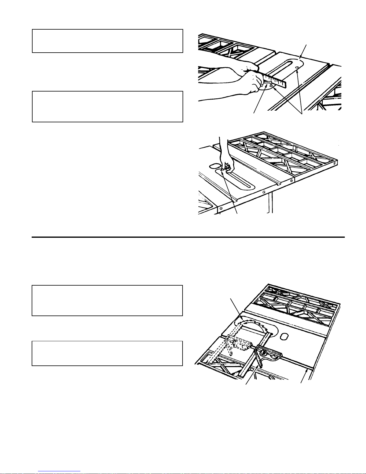
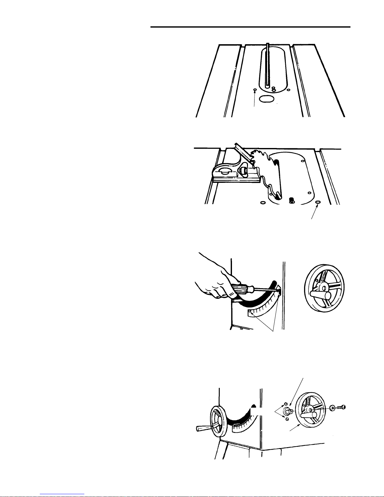
1. Inser t shoul d be flush w ith table top. Check as shown.
Loosen flat head screw that holds insert and adjust the
four set screws as necessar y. Tighten flat head screw.
Do not tighten screw to the point where it bends the
inser t.
CAUTION: Insert must be even with the table surface. Inserts too high or low can let the workpiece
“snag” or catch on uneven edges. Workpiece
could twist and kickback.
2. To remove insert.
a. Make sure saw is off and unplugged.
b. Loosen flat head screw.
c. Lift insert from front end, and pull toward front of
saw.
4. To replace insert.
a. Make sure saw is off and unplugged.
b. Place insert into insert opening in table and push
toward rear of saw to engage spring clip and until
keyslot in insert will drop over flat head screw.
Tighten screw.
c. Do not tighten screw to the point where it bends the
inser t.
Checking Heeling Adjustment or Parallel ism
of Sawblade to Miter Gauge Groove
While cutting, the ma terial mus t move in a straight line parallel to the sawblade. Therefore, both the miter gauge
groove and the rip fence must be parallel to the sawblade.
WARNING: The blade must be parallel to the miter
gauge groove. Misaligned blades could bind on
workpiece. Workpiece could suddenly kickback.
You could be cut or hit.
If the sawblade is not parallel to the miter gauge groove,
the blade will bind at one end of the cut. This is known as
“Heeling”.
WARNING: To reduce the risk of injury from acci-
dental start, make sure switch is “OFF” and plug is
not connected to power source outlet.
To check for parallelism:
1. Raise blade to approximately 3" depth of cut.
2. Mark an “X” on one of the tee th whic h is set ( bent) to
the left.
3. Place the head of a combination square in the left
miter gauge groove. Rotate the blade so that the
tooth marked with an “X” is in front and adjust the
blade of the square so that is just touche s the tip of
the marked tooth. Lock the square at this setting.
Table Insert
3/32 In.
Hex “L” Wrench
Set Screws
Flat Head
Screw
Sawblade
Combination
Square
Miter Gauge
Groove
Page 18
18
Assembly (c ontinued)
NOTE: Hold the head of the combination square firmly
against the edge of the miter gauge groove during all
measurements.
4. Move the square to the rear of the blade. Rotate the
blade so the marked tooth is in the rear and see if the
marked tooth again touches the blade of the square.
5. If the marked tooth touches the square at the front
and at the rear of the sawblade, the blade is parallel
to miter gauge slot. The parallelism is correct. Pro-
ceed to the “Checking Blade Tilt, or Squareness of
Blade to Table”.
6. If square does not touch the m ar ked tooth at th e rear
and front equally (gap is greater that 0.015 inch–
thickness of 4 pages from Owner s Manual) or tooth
interferes with square, the mechanism underneath
must be adjusted to make the blade parallel to the
miter gauge groove.
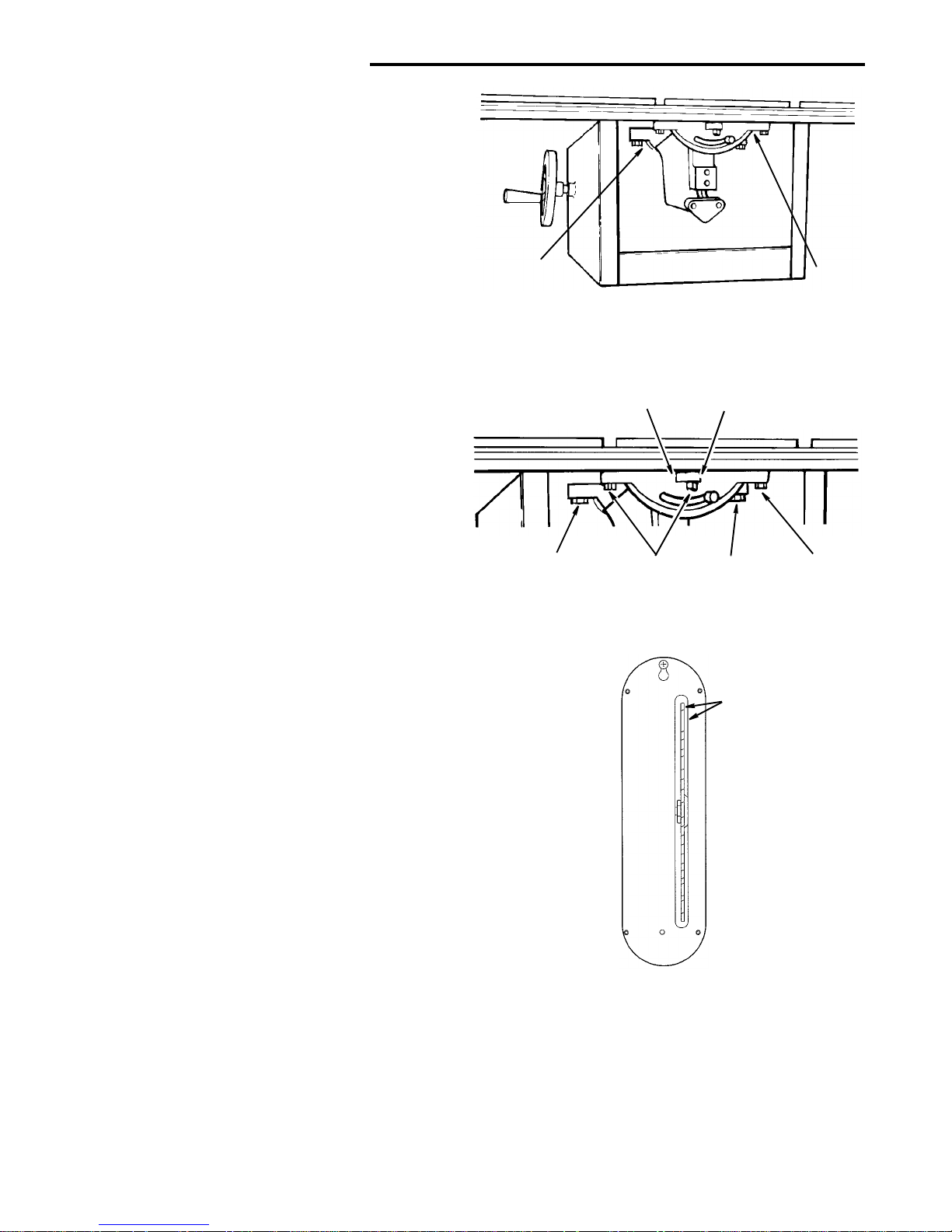
7. Tighten the tilt lock handle located at the fro nt of the
saw.
8. Loosen the left and right micro-adj ust set screws on
the center lug of the rear trunnion.
9. Loosen the three mounting screws that hold the front
trunnion and the three mount ing s crews that h old th e
rear trunnion using a 9/16" wrench . The front center
trunnion bolt can be accessed through the slot for the
tilt lock handle in the front of the saw.
10. Position the sawblade, by moving the trunnion
assembly, in the slot of the table inser t maintaining a
minimum of 1/8" cleara nce between the r ight side of
the blade and the table insert (viewed from rear of
saw) and with 9/16" wrench , lightly tighten the c enter
bolt on the front trunnion.
11. Lightly tighten the center bolt on the rear trunnion.
12. Standing at the rear of the saw, determine which
direction the rear of the sawblade must move to make
it parallel to the miter slot. To move the rear of the
blade to the right - tighten the right set screw. To
move the rear of the blade to the left - tighten the left
set screw.
NOTE: When tightening one set screw it may be necessary to loosen the opposite set screw first.
13. Using the set screws move the rear of the blade in the
desired directio n. Repeat s teps 3 a nd 4 un til blade is
parallel to miter gauge slot.
14. Tighten the oppo si te set sc rew to h old the trunnion in
position when measur ement at the front and rear of
the sawblade are equal.
15. Secu rely tighten the left and r ight tr unnion screws on
the rear and front turning using a 9/16" wrench.
16. Recheck the mar ked blade tooth at the front and rear
position to insure that the adjustment has not moved.
17. If the adjustment moved, loosen the four bolts and
repeat steps 13 - 15.
18. When the adjustment is correct loosen both set
screws and securely tighten the center bolts on the
front and rear trunnion.
Rear
Trunnion
Trunnion
Front
Front
Screws
Rear
Screws
Rear
Screws
Trunnion
Trunnion
Front
Screws
Trunnion
Trunnion
Rear Trunnion
Set Screws
Rear of
Saw
1/8" Minimum
Clearance
NOTE: Maintain a mi nimum 1/8 inch cleara nce between
the right side of the blade and the table insert (viewed
from rear of saw). This insures clearance when th e blade
is beveled.
Page 19
19
Checking Blade Tilt, or Squareness of Blade
to Table
When the bevel pointer is pointing directly to the “0” mark
on the bevel scale, the sawblade should make a square
cut 90° to the table.
WARNING: For your own safety, turn switch “OFF”
and remove plug from power source outlet.
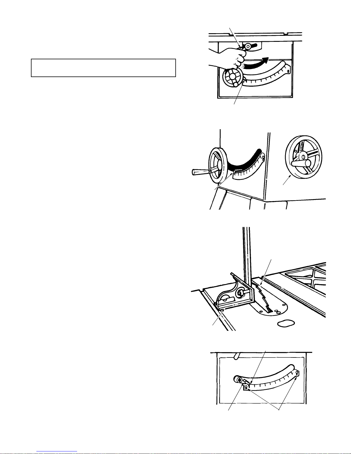
To check for squareness, 90° position.
1. Raise blade to 3" depth of cut.
2. Operate the tilt lock handle (counterclockwise) to
loosen the tilt clamp screw.
NOTE: Handle is spring loaded for engagement with
screw head - must be pushed inward for disengagement whenever necessary to obtain a new grip on
screw head. Always position handle in downward position to prevent binding when raising the blade.
3. Rotate tilt handwheel clockwise a few turns to tilt blade.
Now, rotate handwhe el counterclo ckwise until it stops.
Blade should now be square with table and pointer
should point to “0”.
4. Place the square against blade. Make sure square is
not touching the tip of one of the saw teeth.
A. If blade is square to table
1.Check pointer. If pointer does not point to the “0”
mark on the bevel scale.
a. Remove elevation handwheel.
b. Loosen screw and adjus t p oin ter u sing medium
screwdriver.
c. Install elevation handwheel.
Tilt Lock Handle
Bevel Pointer
Tilt Handwheel
Pointer
Square
Blade
Pointer
Adjusting Screw
Pointer at
0° Position
Scale Adjusting
Screw
Page 20
20
Assembly (c ontinued)
B. If blade is not square to table...the 90° stop
screw must be adjusted.
1.Unscrew 90° stop screw three to four turns us ing
3/16 inch hex “L” wrench.
2.Turn tilt hand wheel clockwise one turn, then tu rn
handwheel counter clockwise unti l blade is squa re
with table.
3.Screw 90° stop sc rew in until it stops. Check once
again for squareness and readjust screw, if necessary.
4.Check pointer as described in step A.
To check for alignment, 45° Position
1. Tilt blade to left as far as it will go.
2. Place an accurate square against blade. Make sure
square is not touching the tip of one of the saw teeth.
A. If blade is 45° to table;
1.Check pointer. If pointer does not point to the 45°
mark on the scale, the scale must be adjusted.
a. Remove elevation handwheel.
b. Loosen two screws on scale and adjust scale
until pointer points to 45° mark.
c. Install elevation handwheel.
B. If blade is not 45° to table, stop screw and scale
must be adjusted.
1.Unscrew 45° stop screw three to four turns us ing
3/16 inch setscrew wrench.
2.Turn tilt handwheel until blade is 45° to the table.
3.Screw 45° stop sc rew in until it st ops. Ch eck once
again and readjust screw, if necessary.
4.Check pointer as described in step A above.
Checking Tilt Mechanism
With tilt lock handle loosened, the handwheel should turn
freely without binding. The turning section can be
adjusted by tightening or loosening the screws in the
bearing retainer.
NOTE: Tilt handwheel must be removed to adju st. W hen
adjusting the screws in the bearing r etainer, hold the nut
inside using a 3/8 inch wrench.
90°
Stopscrew
45°
Stopscrew
Scale Screws
Retainer Bearing
Tilt
Handwheel
Screws
Page 21
21
Assembling Herc-U-Lift™ Caster System
Assembly Tips
1. The caster set con sists of an upp er and lower assembly.
2. First put the upper and lower assembly together following instructions below.
3. Finger tighten all nut and bolt connections. After
mounting the assemblies on the table saw, adjust
frames on center, and then securely tight en all fasteners.
4. When assembling the frames, Tube Rear (27" long)
and Tube Front (13-7/8" long) must be assembled so
the large hole faces down t owards the floor. See the
illustration before assembling.
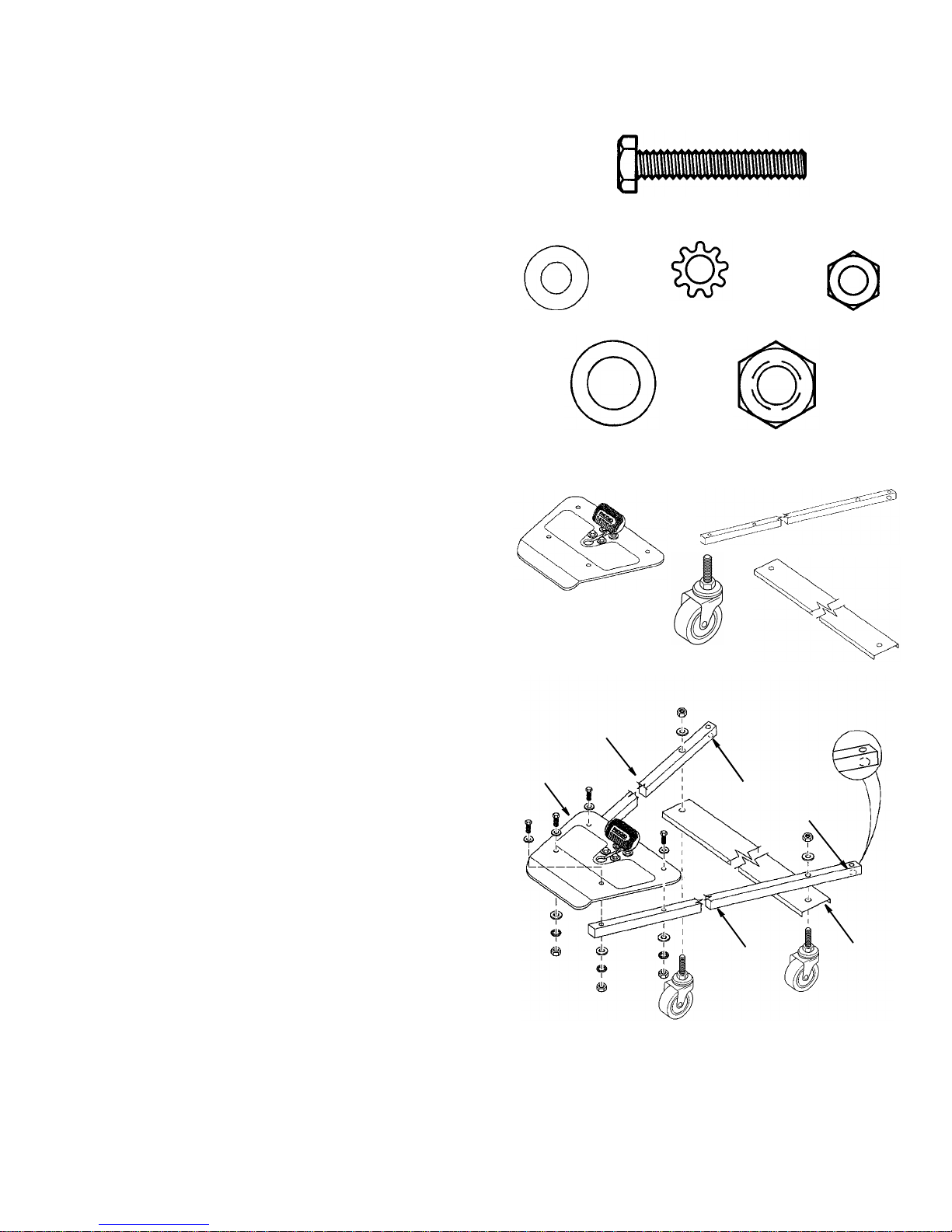
Upper Assembly
1. From bag of loose parts remove the following hardware:
*4 Hex Head Screw, 1/4-20 x 1-1/2
*8 Washers 1/4 ID
*4 Lockwashers 1/4
*4 Hex Nuts 1/4
*2 Washers 7/16 ID
*2 Hex Nuts 7/16
* Items marked with asterisk (*) are shown actual size.
2. From the loose parts find the following:
1Plate Assembly
2 Tube Rear (27" Length)
1 Channel Rear
2Casters
3. Assemble Tube Rear (27 inch length) to each side of the
Plate Assemb ly as sho wn usin g f our each 1/4-20 x 1-1 /2
hex head bolt, flat washe r (each side ), lockwasher and
nut. Finger tighten nuts.
NOTE: The larger hole at the end of the tube, opposite
the plate assembly, must face down.
4. Align rear channel with holes in the rear tubes as
shown. Assemble caster through chan nel and tube as
shown. Fasten with flat washer and 7/16 nut as shown.
Finger tighten nuts.
7/16 I.D. Washer
7/16 Hex Nut
1/4-20
1/4 I.D.
Lockwasher
1/4 I.D.Washer
Hex Nut
1/4-20 x 1-1/2
Hex Head Screw
Plate Assembly
Caster
Channel Rear
Tube Rear
Tube Rear
Large Hole
Facing Down
Tube Rear
Channel
Rear
Plate
Assembly
Page 22
22
Assembly (c ontinued)
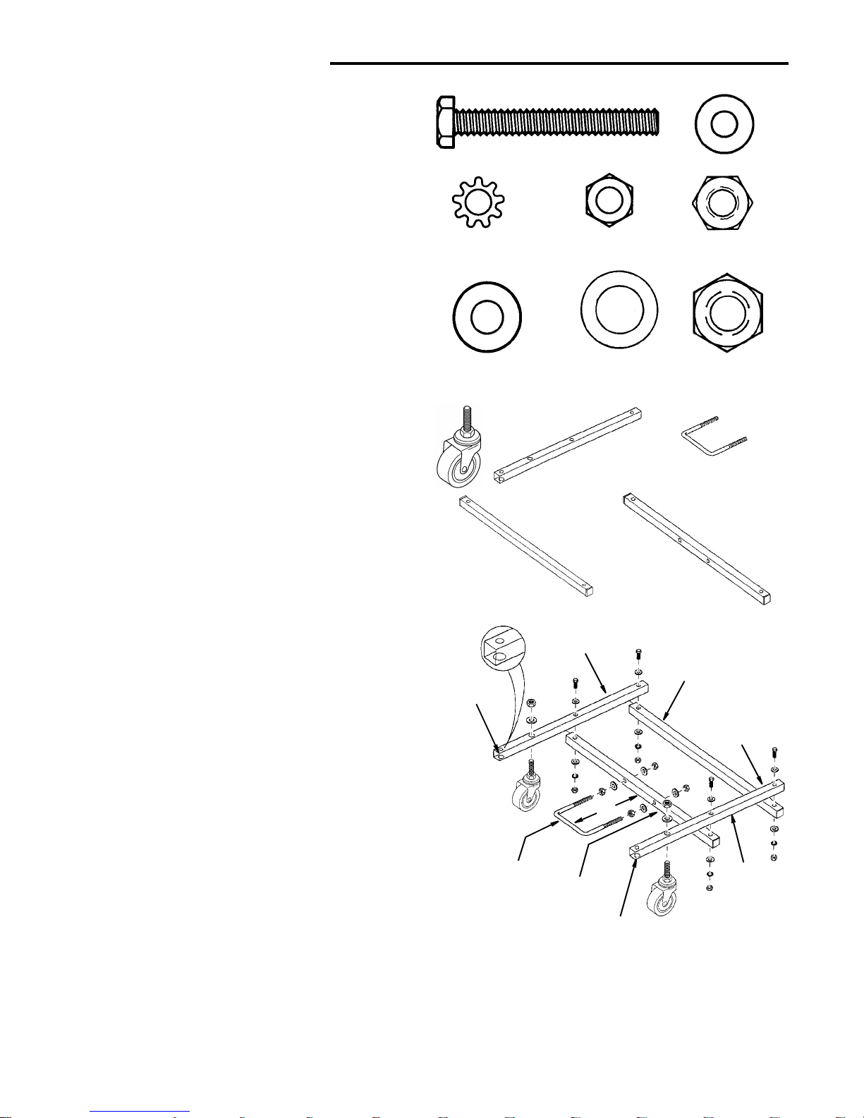
Lower Assembly
1. From bag of loose parts remove the following hardware.
*4 Screw 1/4-20 x 2
*8 Washer 1/4 I.D.
*4 Lockwasher 1/4 I.D.
*4 Nut Hex 1/4-20
*4 Nut 5/16-18
*4 Washer 5/16 I.D.
*2 Washer 7/16 I.D.
*2 Nut Hex 7/16
1U-Bolt
2. From the loose parts find the following:
2Caster
2 Tube Front (13-7/8" Long)
1 Tube Support (17-1/4" Long)
1 Tube U-Bolt (19-5/8" Long)
3. Assemble support tube (17-3/4 inch length) to both front
tubes (13-7/8 inch length) using two each 1/4-20 x 2 hex
head bolt, flat washer (each side), lockwash er and nut
as shown. Finger tighten nuts.
NOTE: The larger hole at the end of the front tube
must face down as shown.
4. Align and assemble U-bolt tube (19-5/8 inch length)
with holes in the fron t tube using two each 1/4- 20 x 2
hex head bolt, flat washer (each si de), l ockwasher an d
nut as shown. Finger tighten nuts.
5. Assemble 5/16 nut and flat washers on each side of Ubolt as shown.
6. Place U-bolt through holes in U-bolt tube, finger tighten
two flat washers and 5/16 nuts on each side of U-bolt
as shown.
7. Adjust U-bolt about two inches from tube.
8. Assemble caster through tube. Fasten with 7/16 flat
washer and 7/16 nut as shown. Tighte n nuts securely.
Use adjustable wrench on caster stem hex to keep
stem from turning while tightening nut.
1/4 I.D. Washer
1/4 Lockwasher
1/4-20 x 2
Hex Head Screw
5/16-18 Nut
7/16 I.D. Washer
7/16 Nut Hex
5/16 I.D. Washer
1/4-20 Nut Hex
Tube Front
Tube Support
Tube U-Bolt
U-Bolt
Tube Front (Assembled On Top)
Tube Support
U-Bolt
Tube Front
Tube
Tube Front
Large Hole
Facing Down
Large Hole
Facing Down
U-Bolt
2
"
(Assembled
On Top)
Assemble each tube exactly as shown.
Note both front tubes are placed on top of the
tube U-bolt and tube support as shown.
Page 23

23
Assembling Herc-U-Lift™ Caster System to
Saw
Installation Instructions
WARNING: To reduce the risk of injury from unexpected starting, unplug the tool before attaching
caster set.
1. From the bag of loose parts remove the following hardware:
*4 Screw Special 1/4-20 x 1-5/8
*8 Washer 1/4 I.D.
*4 Nut Lock 1/4-20
*8 Screw Hex Hd. 1/4-20 x 1/2
*8 Lockwasher 1/4
*8 Nut Hex 1/4-20
2. From the bag of loose parts remove the following:
4 Leg Brackets
3. Install the four leg brackets on the inside of each leg
using 1/4-20 x 1/2 hex head bolts, lockwashers and
nuts. Tighten bolts secure ly.
4. It may be helpful to place the saw leg stand as sembly
on blocks of wood approximately 3/4 inches thick while
installing the caster assemblies.
5. Place the Lower Assembly under the saw with the front
ends of the tube under the front leg brackets. Install the
special screw (1/4-20 x 1-5/8) through the front leg
bracket and tube as shown. Install the washer (each
side) and lock nut and tig hten the lock nuts until flush
with bottom of screw. The screw should freely pivot
side to side.
6. Place the upper assembly under th e saw (see illustration) with the rear ends of the tube under the leg brackets and install the special screw (1/4-20 x 1-5/8),
washer (each side) and nut in the same manner as
step 5. Center the upper tubes between the lower
tubes and tighten all hard ware at this time beginn ing
with the four (4) bolts attac hing the plate assembly to
the tubes.
7. Insure the upper tube s remain centered between the
lower tubes and tighten the hardware on the lower
assembly.
8. Press down on the plate assembly and check alignment of the U-bolt. The U-bolt should be centered
within the latch mec hanism as shown. Release pe dal
and adjust the U-bolt as necessary, then tighten the
nuts holding the U-bolt to the tube.
1/4-20 x 1-5/8
Screw Special
1/4-20 x 1/2
Screw Hex Hd.
1/4 I.D. Washer
1/4-20
Nut Hex
Leg Bracket
1/4 Lockwasher
1/4-20
Nut Lock
Plastic Ring
Center Frames Equal
Distance on Each Side
Tighten all Nuts
Wood
Block
Latch
Mechanism
U-Bolt
Adjust U-Bolt
Centered Within
Latch Mechanism
Page 24

24
Assembly (continued)
Operation of Herc-U-Lift™ Caster System
The caster set is activated by pressing down on the metal
platform. This will raise t he table saw and allow the saw
to be moved to desired location.
To lower the table saw, press down on the foot pedal.
Make sure the saw firmly rests on the floor. Adjust the
rubber leveling feet if necessary.
Page 25

25
Installing Front Rip Fence Guide Bar
1. From the bag labeled “Guide Bars” remove only the following hardware:
5 Square Head Bolts, 5/16-18 x 1" Long
5 Lockwashers, 5/16 External Type
5 Flat Washers, 21/64 x 5/8 x 1/16
5 Hex Nuts, 5/16-18
2. From the fence guide bar carton find the following:
1 Front Guide Bar (Long)
3. Inser t five 5/16-18 x 1” long s quare hea d bolts into the
holes as shown.
4. Attach flat washer, lockwasher and hex nut loosely, as
shown, so the bolt head protrudes through the front
edge of the table and extension.
5. Slide the front gu ide bar slot over each of the square
head bolts as shown and finger tighten the five nuts.
6. The front guide bar mus t be aligne d left to ri ght at th is
time. Align the 7-1/8 inch ma rk on the right rip scale
with the right edge of the cast iron table top.
7. Push front guid e bar against the saw table and extensions. Finger tighten each nut on the table and extensions. The guide bars will be aligned and the nuts
tightened at a later time.
WARNING: Front and rear guide bars must be
aligned with blade. Misaligned guide bars could
twist. Twisted guide bars could misalign fence. A
misaligned fence could cause binding or kickback.
You could be hit or cut.
5/16-18 x 1 In.
21/64 I.D.
5/16 In. External
Lockwasher
Square Head Bolt
Flat Washer
5/16-18
Hex Nut
Square Head
Bolt
Hex Nut
Lockwasher
Flat
Washer
Square Head
Bolt
Front
Guide Bar
Front of Table
Or Extension
Front
Guide Bar
7-1/8" Mark on
Right Hand
Rip Scale
Right Edge
of Table
Miter Gauge
Groove
Page 26

26
Assembly (c ontinued)
Installing Rear Fence Guide Bar
1. From the bag labeled “Guide Bars” remove only the following hardware:
5 Square Head Bolts, 5/16-18 x 1" Long
5 Lockwashers, 5/16 External Type
5 Flat Washers, 21/64 x 5/8 x 1/16
5 Hex Nuts, 5/16-18
2. From the fence guide bar carton find the following:
1 Rear Guide Bar (Short)
3. Inser t five 5/16-18 x 1” long s quare hea d bolts into the
holes as shown.
4. Attach flat washer, lockwasher and hex nut loosely, as
shown, so the bolt head protrudes through the rear
edge of the table and extensions.
5. Slide the rear g uide bar slot over each of the square
head bolts, similar to the front guide bar assembly.
6. Position a framing square or straightedge against
either side of the blade. Move the rear guide bar righ t
or left until the indicator mark is aligned with the
straightedge.
7. Push rear guide bar against the saw table and extensions. Finger tighten each nut on the table and extensions. The guide bars will be aligned and the nuts
tightened at a later time.
8. Shims may be required between the rear guide bar
and saw table. See instructions for adjusting rip fence
guide bars.
WARNING: Front and rear guide bars must be
aligned with blade. Misaligned guide bars could
twist. Twisted guide bars could misalign fence. A
misaligned fence could cause binding or kickback.
You could be hit or cut.
5/16-18 x 1 In.
Square Head Bolt
5/16 In. External
Lockwasher
5/16-18
Hex Nut
21/64 I.D.
Flat Washer
Square Head
Bolt
Flat
Lockwasher
Hex Nut
Washer
Rear
Guide Bar
Rear of Table or
Extension
Square Head
Bolt
Straight Edge
Mark on
Rear Guide Bar
Page 27

27
Adjusting Rip Fence Guide Bars
WARNING: Front and rear guide bars must be
aligned with blade. Misaligned guide bars could
twist. Twisted guide bars could misalign fence. A
misaligned fence could cause binding or kickback.
You could be hit or cut.
Installing Shims
1. From the bag labeled “Guide Bars” remove the following hardware:
*10 Very thin shim washers.
2. Loosen the 5 nuts holding the rear guide bar in place.
3. Holding the guide bar against the rear of saw table and
extensions, note if there is any gap between the table
or extension and the inside face of the rear guide bar. If
no gap exists, finger tighten nuts. If gap appears, slip
shim washers into gap until space is full.
4. Stack shim washers on table or extension nearest t o
bolt that is affected.
5. When all five bolt loc ations have been checked, slide
guide bar off of bolts and inst all stacks of shim washers under head of appropriate bolt(s).
6. Reinstall rear gui de bar and realign the “mar k” on rear
guide bar as described earlier. Finger tighten nuts.
Aligning Rip Fence Guide Bars
1. Position rip fence over right miter gau ge groove. While
holding up rear of rip fence engage front end of rip
fence onto the front guide bar. Now lower rip fence
down onto table.
2. Open owners manual so that 8 pages are separated
from the rest of the book. Use these pages like a feeler
gage to set the spacing between the bottom of the
fence and the table top.
3. Rip fence should clear saw table/extension surface just
enough to allow pages to slide back and forth under rip
fence. If rip fence is too high or too low, loo sen nuts
holding front guide bar and adjust bar up or down.
Wrench tighten nuts when proper alignment is
achieved.
4. Adjust rear guide bar, as noted above.
5. Slide fence left and r ight on gu ide bar to ensure cl earance from side to side and from front to back. If necessary readjust rip fence guide bars to get proper
clearance. Wrench tighte n all nuts holding guide bars
in place.
NOTE: During this adjustment, the left/right positioning of
the guide bars could be affected. Realignment may be
necessary.
Very Thin
Shim Washer
Shim
Table or
Extension
Rear Guide Bar
Washers
Owners Manual
8 Pages
Page 28

28
Assembl y (contin ued)
Rip Fence Alignment Adjustment
WARNING: A misaligned fence can cause kickbacks
and jams. To reduce the risk of injury, follow these
instructions until the fence is properly aligned.
1. The rip fence must be PARALLEL wi th the sawblade
and miter gauge grooves. Clean any debris off the
fence guide bars. Move fence until it is along side the
miter gauge groove and lock it. It should be p arallel to
groove. If it is not:
a. Unlock fence.
b. Using a 5/32" hex “L” wrench, loosen the four button head
screws located to each side of the rip fence handle.
c. Hold fence head tightly against front guide bar. Align
fence channel so that it is parallel with groove. Care-
fully lock the fence in this position.
d. Alternately tighten the screws.
e. Recheck alignment.
f. Repeat steps as needed until fence channel is
aligned with miter gauge groove.
Rip Fence Lock Lever Adjustment
WA RNING: Make sure the fence l ock w orks in t he center and at each end of the fence guide bar. An improperly adjusted fence could move. Movement could
cause binding or kickback. You could be hit or cut.
1. The rip fence lock lever when locked down should hold
the rip fence securely. The lever should not be difficult
to push down and lock.
To assure proper fence lock adjustment:
a. Raise lock lever and push fence head toward rear of
saw.
b. Hold fence head down onto front guide bar while lift-
ing rear of fence up and down.
c. Tighten adjusting nut until fence clamp just barely
touches rear guide bar.
d. This should provide the best fence adjustment pos -
sible without over tightening.
Check fence lock across entire bar length. Recheck fence
parallelism with miter slot in locked position and adjust if
necessary.
If the fence does not clamp the same across the entire
length of the bars, the guide bars may need to be readjusted with shims provided.
Adjusting Fence Indicator
1. Place rip fence on saw table so that it lightly touches
the right side of the blade and lock it in this position.
2. Loosen pan head screw. Adjust the indicator so that
the red line is located over the “Zero ” line of the right
rip scale and tighten screw.
Miter Gage Groove
Button Head Screws
for Adjusting Fence
Parallelism
Adjusting
Nut
Fence
Rear Guide Bar
Clamp
Fence Clamp and Rear Guide Bar
Should Barely Touch When
Fence is Raised
Indicator at
“Zero” Line
Page 29

29
Installing Blade Guard
1. From the bag labeled “Blade Guard” remove the following parts:
2 Hex Head Screws, 1/4-20 x 5/8" Long
2 Hex Nuts, 1/4-20
2 Lockwashers, 1/4 External Type
1 Thumb Screw
1 Spreader Support
From the blade guard carton find the following:
1 Blade Guard
2. Slide spreader support onto spreader rod until notches
engage pin. Thread thumbsc rew into tapped hole and
hand tighten.
3. Attach spreade r to spreader suppor t so that the edge
of the spreader is even with the edge of the spreader
support as shown. Tighten screws with a 7/16 wrench.
4. Raise blade all the way up, make sure it is square with
table.
5. Loosen both hex head screws holding blade guard
support to cradle.
6. Raise blade guard. Lift up both anti-kickback pawls.
Insert a large set screw wrench in the notches of the
pawls to hold the pawls out of the way. Align spreader
square to table as shown.
7. Tighten both hex head screws.
1/4-20 x 5/8 In
Hex Hd Screw
1/4-20 Hex Nut
1/4 In. External
Lockwasher
Spreader
Support
Spreader
Hex Nut
Lockwasher
Square
Hex Hd.
Screws
1/4-20 Hex
Head Screw
Align
Edges
Blade
Guard
Support
Spreader Support
Thumb Screw
Cradle
Pin in
Support
Notches of
Thumb
Screw
Spreader Rod
Located in Blade
Guard Support
Blade Guard
Page 30

30
Assembly (continued)
Aligning Blade Guard
1. Lay blade of square or other straightedge alongs ide of
blade.
2. Loosen socket set screw in gua rd support and move
spreader left or right so that it touches blade of square.
Tighten screw. Socket set screw must tighten against
the spreader rod flat.
NOTE: The spreader is now square with the table and
approximately in line with the sawblade. The spreader
requires further adjustment to align it parallel to the
blade and in the middle of the cut (kerf) made by the
sawblade.
IMPORTANT: To work properly, the spreader must
always be adjusted so the cut workpiece will pass on
either side of the spread er without bindin g or skewing to
the side.
NOTE: The spreader is thinner than the width of the c ut
(kerf) by approximately six thicknesses of paper.
3. Make two folds in a small piece (6 x 6 i nch ) o f ordi nary
newspaper making three thicknesses.
The folded paper will be used as “spacing gauge”.
4. Place rip fence on the r ight hand side of table. Carefully move it against blade so th at it is parallel to the
blade, and just touches tip s of saw teeth. Tighten rip
fence lock lever.
5. Insert folded paper between spreader and fence.
6. Using 7/16 wr enc h loo se n th e 1 /4- 20 hex head sc rews
so the spreader can slide sideways.
7. Hold spreader flat against folded paper and fence.
Tighten screws using 7/16 inch wrench.
8. To remove blade guard and spreader, loosen thumbscrew. Do not loosen other screws. This allows you
to remove and replace the guard for non-through cuts
without disturbing the spreader alignment.
Anti-Kickback
Pawls
Set Screw
Wrench
Straightedge
Socket Set
Screw In
Along Side
of Blade
Guard Support
Spreader
Kerf
W ood
Blade
Paper
Spreader
Space Equal to Approx.
3 Thicknesses of Paper
Looking Down on Saw
7/16 In.
Folded Paper
Wrench
Hex Head Screws
Page 31

31
Mounting the Motor
1. Remove Motor Assembly from motor carton.
2. Loosen the two hex head screws that lock the p ins in
the cradle.
3. Lift motor and insert the two pins on motor support
assembly into holes in cradle. Push motor in as far as it
will go. Do not tighten screws at this time.
Installing Belt
1. Locate the motor belt
2. Lower the blade all the way down and set bevel to 0°.
3. Install belt on saw pulley and motor pulley.
4. Sight along edges of both pulleys check that the belt is
parallel to the edges of bot h pulleys. If not, use a Hex
“L” wrench to loos en th e set screw on th e moto r pu lley.
Reposition the motor pulley and securely tighten the
set screw on the motor pulley.
5. Raise saw blade all the way up.
6. Lift motor until edge of wash er (see il lu stration) is even
with end of slot in motor support assembly. In this position, pull motor toward you (pins will slide in the cradle)
until slack is removed from belt. Make sure edge of
washer is still even with end of slot. Using a 1/2 inch
wrench tighten the two motor suppor t assembly clamp
screws.
Motor
Pins
Motor Support
Assembly
Cradle
Hex Head Screws
Motor Support
Assembly
Motor Support
Assembly Clamp
Screws
Cradle
Washer
Slot in Bracket
Edge of Washer
Even With End
of Slot in Bracket
Motor
Pins
Pivot Screw
Poly-V Belt
Page 32

32
Assembly (contin ued)
7. Put your hand around the belt half way between the
two pulleys and squeeze belt until two sides of belt
touch. The motor sho uld move freely as you squeeze
the belt. If motor does not move freely, the motor must
be repositioned as described above.
Do not attempt to tighten the pivot screw. It must
slide freely in slot as the blade is raised and lowered.
Installing Belt Guard
1. From the bag labeled “Misce llaneous” remove the following hardware:
4 Hex Nuts, 10-32
8 Flat Washers, 13/64 x 3/8 x 1/32.
From among the loose parts find the following:
1Belt Guard
2. Lower blade all the way down and remove the motor
belt.
3. Install one flat washer onto each of the four motor
studs.
4. Open the hinged belt g uard by press ing down on the
tab lock as shown.
5. Position the guard so the large hole fits around the
pulley. Ins ert the motor studs th rough the four small
holes as shown.
6. Attach another washer and one nut to each motor
stud as shown and tighten securely.
7. Reposition the belt on the motor and arbor pulley.
8. Close the hinged cover secur ely until the tab snaps
and locks the cover closed.
9. Check the belt clearances on the guard by raising the
blade to full height using the elevation handwheel.
10. Check motor cl earances by rotating the bevel handwheel located on the right side until the indicator is
set at 45°.
10-32 Hex Nut
Belt Guard
Press Down on T ab
Flat Washer
13/64 I.D.
Lock To Open
Motor
Stud
Flat
Washer
Belt
Guard
Hex Nut
Flat
Washer
Page 33

33
Mounting Switch and End Caps
1. From the bag labeled “Misc el laneous” remove only the
following hardware:
2 Pan Head Screws, 10-32 x 3/8" Long
2 Lockwashers, #10 External Type
2 Square Nuts, 10-32
4 Pan Head Screws, Type “AB” 8 x 1/2" Long
2 Rear Stop Washers
From the bag labeled “Trim” remove the following:
4 Plastic End Caps
1Key Switch
2. Inser t the 2 10-32 x 3/8" pan head scr ews with lockwashers through the outermost holes in switch assembly.
3. Install the 2 square nuts o n the s crews so that the re is
an 1/8"+ clearance between the ins ide of the nut and
the top of the switch assembly bracket.
NOTE: Switch assembly may be mounted on left or right
hand side of saw.
Mounting Switch on Right Side
1. Slide the nuts i nto the lower slot of t he front guide b ar
from the right end, with the switch facing front.
2. Slide switch assem bl y left until the left side of switch
assembly is in l ine with right side of main s aw table tighten screws.
Mounting Switch on Left Side
1. Slide the nuts i nto the lower slot of t he front guide b ar
from the left end, running wire be hind unit, with switch
facing front.
2. Slide the assembly right until the right side of the
switch assembly is in line with the left side of the main
saw table - tighten screws.
Securing Electrical Cords
1. From the bag labeled “Large Parts” find the following:
3Wire Ties
Switch Mounted on Right Side
2. Route motor cord a nd power cord along right side of
cabinet. Use a hamm er to lightly tap the pointed tabs
on the wire ties into the two holes provided on the right
side of cabinet. Secure both cords in wire ties.Loop
motor cord in rear wire tie to remove excess slack.
NOTE: One wire tie is extra.
Switch Mounted on Left Side
1. Route motor cord and power cord along left side of
cabinet. Use a hamm er to lightly tap the pointed tabs
on the wire ties into the three holes provided on the left
side of the cabinet. Secure both cords through wire
ties.
#10 Externa l
Lockwasher
Pan Head Screw
10-32 x 3/8"
Rear Stop Washer
10-32
Square Nut
Plastic End Caps
Square Nut
Lockwasher
10-32 x 3/8 Pan
Front Guide
Bar
Switch Assembly
Head Screw
Bracket
Type “AB” 8 x 1/2
Pan Head Screw
Key Switch
Wire Tie
Wire Tie
Two Cords
Page 34

34
Assembl y (contin ued)
Installing Guide Bar End Caps
1. The left and right end ca ps for front guide bar c an be
installed at t his time. Ali g n t he pl as t ic end cap to mat ch
profile of bar.
2. Install self tapping 8-32 pan head screw into each hole.
3. The left and r ight end caps for rear guide ba r can be
installed at this time.
NOTE: Two large washers are supplied. These act as
fence stops so the rear of the fence does not fall off the
rear guide bar.
4. Install rear end caps and fence stops as shown.
NOTE: This completes the assembly of your table saw.
Do not throw away any remaining hardware until you
have read the entire owners manual.
Front End
8 x 1/2 Ty “AB”
Cap
Rear End
Cap
Rear
Stop Washer
Pan Head Screw
Page 35

35
Getting to Know Your Table Saw
6 Miter Gauge
9 Sawblade
7 Blade Guard
8 Table Insert
5 Rip Fence
10 Ind-I-Cut
2 Elevation
Wheel
11 Micro-Adjust
Rip Fence
1 On-Off
Switch
12 Casters
13 Miter Gauge
and Rip Fence
Storage Hooks
3 Tilt Handwheel
4 Tilt Lock
Handle
1. On-Off Switch.
CAUTION: Before turning switch “ON”, make sure
the blade guard is correctly installed and operating
properly.
The On-Off Switch has a l ocking feature. This feature is
intended to help prevent unauthorized and pos sible hazardous use by children and others.
A. To tur n saw ON, insert key, stand to either side of
the blade, never in line with it, place finger under
switch lever and pull end of lever out.
After turning switch ON, always allow the blade to
come up to full speed b efore cutting. Do not cycl e
the motor switch on and off rapidly, as this may
cause the sawblade to loosen. In the event this
should ever occur, allow the sawblade to come to a
complete stop and reti ghten the arbor nut normally,
not excessively. Never leave the saw while the
power is “ON”.
B. To tur n saw OFF, PUSH lever in. Never leave the
saw until the cutting tool has come to a complete
stop.
C. To lock switch in OFF position, hold switch I N with
one hand, REMOVE key with other hand.
WARNING: For your own safety, lower blade or
other cutting tool below table surface. (If blade is
tilted, return it to vertical, 90°, position.) Always
lock the switch “OFF”. When saw is not in use,
remove key and keep it in a safe place. Also, in the
event of a power failure (all of your lights go out)
turn switch off, lock it and remove the key. This will
prevent the saw from starting up again when the
power comes back on.
Key
Switch
Page 36

36
Getting to Know Your Table Saw (continued)
2. Elevation Handwheel...elevates or lowers the
blade. Turn c lockwise to elevate, counterclockwise t o
lower.
3. Tilt Handwheel...tilts the blade for bevel cutting.
Turn c lockwise to tilt toward left, countercl ockwise to
tilt toward right.
When the blade is tilted to the left as far as it will go,
it should be at 45° to the t able and the bevel pointer
should point 45°.
NOTE: There are limit stops inside the saw which
prevent the blade from tilting beyond 45° to the left
and 90° to the right. (See “Adjustments a nd Alignments” section “ Blade Tilt, or Squareness o f Blade
to Table”).
4. Tilt Lock Handle...locks the blade in the desired
tilt position. To loosen, turn counterclockwise. Push
handle in and turn it to another pos ition if necessar y
in order to tighten or loosen.
IMPORTANT: Be sure handle is hanging in the
“DOWN” position before tilting blade. If it is pointing
to the 1 o’clock position i t may jam on underside of
the table and bend the locking bolt.
5. Rip Fence...is locked in place by pushing the lock
lever down until the lever rests on the stop. To move
the fence, lift the lock lever and grasp the fence with
one hand at the front.
A “T” slot is provided in the rip fence for attaching a
wood facing when using the dado head, or molding
head.
Select a piece of smooth s traigh t wood approxima tely
3/4 inch thic k, an d the sam e size as the rip fence.
Attach it to the fence with the three square head
bolts, nuts and washers provided in bag labeled
“Miscellaneous”. To remove the facing, loosen the
hex nuts, slide the facing toward the rear and out of
the fence slot.
6. Miter Gauge...head is locked in position for cross
cutting or mitering by tightening the lock knob.
Always securely lock it when in use.
There are adjustable screw stops for the stop pin 0 °
and 45° right an d left positions for conveniently setting the miter gauge to c ut miters at these standard
angles.
7. Blade Guard...must always be in place and
working properly for all thru-sawing cuts. That is, all
cuts where the blade cuts completely through the
workpiece.
To remove the guard for special operations, loosen
the thumbscrew and slide the guard off the rod. Do
not disturb the setting of the rod.
When replacing the guar d make sure the pin in the
rod engages with the notch in the spreader suppor t.
Make sure the thumbscrew is tightened securely.
8. Table Insert...is removable for removing or install-
ing blade or other cutting tools.
WARNING: To reduce the risk of injury from acci-
dental start, turn switch “OFF” and remove plug
from power source before removing insert.
A. Lower the blade below the table surface.
B. Raise blade guard.
C. Loosen insert screw.
D. Lift insert from front end, and pull toward front of
saw.
WARNING: Never operate saw without the proper
insert in place. Use the sawblade insert when sawing. Use the combination dado molding insert
when using a dado or molding head.
Flat
Washer
Lockwasher
Hex
Wood Facing
Fence
Nut
Square Head
Bolt
1-3/8
9/32
Diameter
Hole
Counterbore
3/4 Diameter
x 3/8 Deep
3"
Minimum
3/4"
Page 37

37
9. Removing and Installing Sawblade
WAR NI NG: To reduce the risk of inju ry from acciden-
tal start, turn switch “OFF” and remove plug from
power source outlet before removing or installing
sawblade.
A.Raise blade guard, remove insert.
B.To remove blade, place a block of wood against front
of blade, pull arbor wrench toward you to loosen
arbor nut.
C. To tighten arb or nut, place a block of wood against
rear of blade, push wrench away from you.
When installing the blade, make sure the teeth are
pointing toward the front of the saw and that the blade
and collars are clean, and free from any burrs.
The hollow side of the collar must be against the blade.
Always tighten the arbor nut securely.
NOTE: When using the dado or molding head, it is not
necessary to install the outer (loose) blade collar.
D. To replace i nsert, place inser t into opening in table
and push toward rear of saw to engage rear spring
on insert and until keyslot in insert will drop over
screw. Tighten screw. Do not tighten screw to the
point where it will deflect the insert.
WARNI NG: To reduce the risk of injury from a thr o wn
workpiece, blade parts, or blade contact, never operate saw without the proper inser t in place. Use the
sawblade insert when sawing. Use the proper size
dado/molding insert for dado blades and molding
heads.
10. Ind-I-Cut
The plastic disc em bedded in the table in front of the
sawblade, is provided for marking the location of the
“sawcut” (kerf) on the workpiece.
Check disk location: If it is above table surface, place a
piece of hardwood on top of it and tap it down with a
hammer.
Marking the Ind-I-Cut:
A. Wi th blade 90 ° (squa re to table) and m iter gau ge in
left groove, cross cut a piece of wood holding the
wood firmly against miter gauge.
B. Pull miter gauge back until freshly cut edge of wood
is over disk. Using a shar p pencil, mark a line on
disk at freshly cut edge of wood.
C. With miter gauge in righ t hand groove, follow same
procedure and mark another line on disk.
D. These lines indicate the “path” of the cut (kerf)
made by the sawblade.
E. Whe n cutting the wor kpiece, line up mark on work-
piece with line on disk.
NOTE : When the blade is changed, or a dado/molding
head installed the se l ines will need t o be er ased and re set.
W ood
Block
L
o
o
s
e
n
Wood
Block
Arbor Nut
Blade Collar
Arbor
Teeth Pointing
To Front of Saw
T
i
gh
t
e
n
Marking
Ind-I-Cut
Using
Ind-I-Cut
Page 38

38
Getting to Know Your Table Saw (continued)
11. Micro-Adjust Rip Fence...allows the operator
to accurately adjust the rip fence using only one
hand. To move the fence push in on the micro-adjust
knob and rotate.
12. Herc-U-Lift™ Caster Operation
The caster set is activated by pressing down on the metal
platform. This will raise the table saw and allow the saw
to be moved to desired location.
To lower the table saw, press down on the foot pedal.
Make sure the saw fir mly rests on the floor. Adjust the
rubber leveling feet if necessary.
13. Storage Hooks
Conveniently holds rip fence and miter gauge when not in
use.
Micro Adjust
Knob
Miter Gauge
Rip Fence
Page 39

39
Safety Instructions for Basic Saw Operations
Before Each Use
Inspect your saw.
• To reduce the risk of injury from accidental starting,
turn the switch off, unplug the saw, and remove the
switch key before raising or removing the guard,
changing the cutting tool, changing the setup, or
adjusting anything.
• Check for alignment of moving parts, binding of moving
parts, breaka ge of parts, saw stability, and any other
conditions that may affect the way the saw works.
• If any part is missing, bent or broken in any way, or any
electrical par t does not work pro perly, turn the saw off
and unplug the saw.
• Replace damaged or missing parts before using the
saw again.
• Use the sawblade guard, spreader and anti-kickback
pawls for any thru-sawing (whenever the blade comes
through the top of the wor kpiece). Make sure th e antikickback pawls work properly. Make sure the spreader
is in line with sawblade.
• Remove adjusting keys and wrenches. Form a hab it o f
checking for and removing keys and wrenches from
table top before turning saw on.
• Make sure all clamps and locks are tight and n o par ts
have excessive play.
To Reduce the Risk of Injury From Jams, Slips Or Thrown Pieces (Kickbac ks Or Throwbacks)
Inspect Your Blade.
• Choose the right blade or cutting accessory for the
material and the type of cutting you plan to do.
• Never use grinding wheels, abrasive cutoff wheels,
friction wheels (metal cutting blades) wire wheels or
buffing wheels. They can fly apart explosively.
• Cut only wood, wood like or pla stic materials. Do not
cut metal.
• Choose and inspect your cutting tool carefully:
- To reduce the r isk of cutting tool failure and thrown
shrapnel (broken pieces of blade), use only 10” or
smaller blades or other cutting tools marked for
speeds of 5000 rpm or higher.
- Always use un broken, balanced blades designed t o
fit this saw’s 5/8 inch arbor.
- When thru-sawing (making cuts where the blade
comes through the wor kpiece top), always use a 10
inch diameter blade. This keeps the spreader in closest to the blade.
- Do not over tighten arb or nut. Us e ar bor wr en ch es t o
“snug” it securely.
- Use on ly sharp blades with pr operly set teeth. Consult a professional blade sharpener when in doubt.
- Keep blades clean of gum and resin.
- Never use the saw without the proper blade insert.
Inspect your work area.
• Keep work area clean.
• Cluttered areas and benches invite accidents. Floor
must not be slippery from wax or sawdust.
• To reduce the r is k of bur ns or othe r fi re dam age, never
use the saw near flammable liquids, vapors or gases.
• To reduce the risk of i njury, don’t do layout, assembly,
or setup work on the table while blade is spi nning. It
could cut or throw anything hitting the blade.
Plan your work
• Use the right tool. Don’t force tool or attachment to do
a job it was not designed for.
Inspect your workpiece.
• Make sure there are no nail s or foreign objects in th e
part of the workpiece to be cut.
• When cutting irreg ular ly shape d wor kpie ces, plan your
work so it will not slip and pinch the blade:
• A piece of molding for example, must lie flat o r be hel d
by a fixture of jig that will not let it twist, rock or slip
while being cut. Us e jigs or fixtures where ne eded to
prevent workpiece shifting.
• Use a different, better suited type of tool for work that
can’t be made stable.
Plan your cut.
• To reduce the risk of kickbacks and throwbacks whic h
occur when a par t or all of t he work piece binds on the
blade and is thrown viol ently back toward the front of
the saw:
-Never cut Freehand. Always use either a rip fence,
miter gauge or fixtur e t o po si tio n a nd gui de the wor k ,
so it won’t twist or bind on the blade and kickback.
- Make sure th ere’s no debris between the workpiec e
and its supports.
• Use extra caution with large, very small or awkward
workpieces.
• Use extra supports (tables, saw horses, blocks, etc.)
for any workpieces large enough to tip when not held
down to the table top. Never use another person as a
substitute for a table extension, or as additional support for a workpiece that is longer or wider than the
basic saw table, or to help feed, support or pull the
workpiece.
• Never confine the piece being cut off, that is, the piece
not against the fence, miter gauge or fixture. Never
hold it, clamp it, touch i t, or use l en gth s to ps agai ns t i t.
It must be free to move. If confined, it could get
wedged against the blade and cause a kickback or
throwback.
• Never cut more than one workpiece at a time.
• Never turn your table saw “ON” before clearing everything except the workpiece and related support
devices o ff the table.
Page 40

40
Safety Instructions for Basic Saw Operations (continued)
Plan Ahead To Protect Your Eyes, Hands, Face and Ears
Dress for safety
• Do not wear loose clothing, gloves, neckties or jewelry
(rings, wrist watches). They can get caught and draw
you into moving parts.
• Wear nonslip footwear.
• Tie back long hair.
• Roll long sleeves above the elbow.
• Noise levels vary widely. To red uce the r isk of poss ible
hearing damage, wear e ar plugs or muffs when us ing
table saw for hours at a time.
• Any power saw can throw foreign objects into the eyes.
This can result in permanent eye damage. Always
wear safety goggles, not glasses, complying with ANSI
Z87.1 (or in Canada CSA Z94-3-M88) shown on pa ckage. Everyday eyeglasses have only impact resistant
lenses. They are not safety glasses. Safety goggles
are available at many local retail stores. Glasses or
goggles not in compliance with ANSI or CSA could
seriously hurt you when they break.
• For dusty operations, wear a dust mask along with
safety goggles.
Plan the way you will push the workpiece through.
• Never pull the workpiece through. Start and finish
the cut from the front of the table saw.
• Never put your fingers or hands in the path of the
sawblade or other cutting tool.
• Never reach in back of the cutting tool with either
hand to hold down or support the workpiece, to remove
wood scraps, or for any other reason.
• Reduce the Risk of hand positions where a sudden slip
could cause fingers or a hand to move into a sawblade
or other cutting tool.
• Don’t overre ach. Alw a ys k eep good f ooti ng and balance .
• Push the workpiece against the rotation of the blade,
never f eed material into the cutting tool from the rear of
the saw.
• Always push the workpiece all the way past the sawblade.
• As much as possi ble, keep your face and body to one
side of the sawblade, out of line with a possible kickback or throwback.
• Set the cutting tool as low as possible for the cut you’re
planning.
Reduce the Risk of Accidental Starting.
• Make sure switch is “OFF” before plugging saw into a
power outlet.
Whenever Sawblade Is Spinning
WARNING: Don’t allow familiarity (gained from frequent use of your table saw) cause a careless mistake. Always remember that a careless f raction of
a second is enough to cause a severe injury.
• Before actually cutting with the saw, watch it while it
runs for a short while. If it makes an unfamiliar noise or
vibrates a lot, stop immediately. Turn the saw off.
Unplug the saw. Do not restart until finding and correcting the problem.
• Make sure the top of the arbor or cutting tool turns
toward the front of the saw.
Keep Children Away.
• Keep all visitors a safe distance from the table saw.
• Make sure bystanders are clear of the table saw and
workpiece.
Don’t Force Tool.
• Let the blade reach full speed before cutting.
• It will do the job better and safer at its designed rate.
• Feed the workpiece into the saw only fast enough to let
the blade cut without bogging down or binding.
Before freeing jammed material.
• Turn switch “OFF”.
• Wait for all moving parts to stop.
• Unplug the saw.
• Check blade, spreader and fence for proper alignment
before starting again.
To reduce the risk of throwback of cut off pieces.
• Use the guard assembly.
To remove loose pieces beneath or trapped inside
the guard.
• Turn saw “OFF”.
•Remove switch key.
• Wait for blade to stop before lifting the guard.
Before Leaving The Saw.
• Turn the saw off.
• Wait for blade to stop spinning.
• Unplug the saw.
• Make workshop child-proof. Lock the shop. Disconnect
master switches. Remove the yellow switch key. Stor e
it away from children and others not qualified to use
the tool.
Page 41

41
Work Feed Devices
Before cutting any wood on your saw, study all of the
“Basic Saw Operations”.
As you learn new table saw woodworking techniques,
you’ll see that many types of c uts need different suppor t
and feeding devices, known as jigs or fixtures. They can
help you make cuts more accurately. By helping to steady
the workpiece and keep you away from the blade, they
can help you safely use your saw for certain cuts.
Many people custom build their own jigs and fixtures. Jigs
and fixtures are often designed for a particular cut.
You can use your table saw to easily make many jigs and
fixtures. To get you started, we’ve included instructions
for some simple ones. After you have made a few practice cuts, make up thes e jig s before sta rting any pr oj ect s.
The use of these devices is explained in “Basic Saw
Operations” section.
Push Stick Featherboard
Make the push stick from a piece of so lid wood. Use a
piece of 1 x 2 (3/4" x 1-5/8" actual) by 15" long.
Make the featherboard from a piece of 8” x 24” x 3/4”
thick solid wood.
Push Block
There are any number of ways to properly cut your wor kpieces to make a push block. The following steps
describe one way you can make a push block.
Making the base:
• Start with a piece of 3/8 inch plywood at least 5-5/8
inches wide or wider and 12 inches long or longer.
• Make two ripcuts. Perform the first ripcut along the side
of the 3/8" wide strip. Next, ripcut the 3/8" plywood to a
width of 5-1/8".
• Crosscut the 3/8" plywood to 12" long.
• Crosscut a 2-1/2" piec e off the 3/8" wide by 3/8" thick
strip and save this short piece for later.
• The next cuts will create the 3/8" by 9-1/2" notc h i n th e
base. Mark the long ed ge o f th e b oar d 2-1/2" fr om on e
end. Make a crosscut into the edge on the mark, st opping about 3/4" into the board. Set the saw and rip the
width to 4-3/4" along the same edge as the stopped
crosscut. Stop the r ipcut where the two cuts i ntersect.
Turn off the saw and remove the base piece. The base
should now measure as shown.
Finished Base
Material for Push Block
Cutting Out the Base
Creating the Notch
90° Notch
Slightly Less Than Thickness
Of Workpiece Up To 3/8"
Kerfs About
5/16" Apart
24"
5"
4-1/2"
8"
Grain
These Edges
Must Be
Parallel
12"
At Least
5-5/8"
2-1/2"
3/8"
4-3/4"
At Least 12"
At Least
5-5/8"
3/8" Thick Plywood
Base
At Least 12"
At Least
5-5/8"
3/4" Thick Plywood
Handle
3/8"
2-1/2" (save)
5-1/8"
4th Cut 1st Cut
2nd Cut
3rd Cut
12"
1st Cut
2nd Cut
4-3/4"
2-1/2"
Page 42

42
Auxiliary Fence
Making the base:
• Start with a piece of 3/8 inch plywood at least 5-1/2
inches wide or wider and 30 inches long or longer.
• Cut the piece to shape and size shown:
Making the side:
• Start with a piece of 3/4 inch plywood at least 2-3/8
inches wide or wider and 27 inches long or longer.
• Cut the piece to shape and size shown:
Putting it together:
• Put the pieces together, as shown:
IMPORTANT: Make sure the screw heads do not stick
out from the bottom of the base, they must be flush or
recessed. The bottom must be flat and smooth enough to
rest on the saw table without rocking.
Cutting Out the Base
Cutting Out the Side
Finished Auxiliary Fence
3/8" Thick Plywood Base
30"
2-5/8
5-1/2
3-1/2
3/4" Thick Plywood Side
27"
3/4" Plywood
3/8"
4-3/4"
This Face and
This Edge Must
Be Parallel
1-1/4
Plywood
Making the handle:
• Miter crosscut a piece of 3/4 inch thick plywood to
shape and size shown:
NOTE: The mitered corners can be any size that looks
like the drawing (about 1-1/2" by 1-1/2").
Putting it Together
• Using good quality woodworking glue, glue the 3/8" x
3/8" x 2-1/2" piece str ip saved earlier to th e base as
shown.
IMPORTA NT: Do not use nails or screws. This is to prevent dulling of the sawblade in the event you cut into the
push block.
• Position the handle at the center of the plywood base
as shown. Fasten them together with g lue and wood
screws.
IMPORTA NT: Make sure the screw heads do not stick
out from the bottom of the base, they must be flush or
recessed. The bottom must be flat and smooth enough to
slide along the auxiliary fence you are now ready to
make.
Screw Head Must Be
Flush Or Recessed
Glue Only
3/8" Plywood Base
3/4" Plywood Handle
Work Feed Devices (continued)
Page 43

43
Basic Saw Operations
Using the Miter Gauge
The miter gauge is used when crosscutting, miter cutting,
bevel cutting, compound miter cutting, dadoing and when
rabbeting across the end of a narrow workpiece.
WARNING: For your own safety, always observe
the following safety precautions in addition to the
safety instructions of pages 3, 4, 5, 6, 39 & 40.
Additional Safety Instructions for Crosscutting
Before Starting:
• Never use the rip fence when crosscutting except as
specifically instructed.
• An auxiliar y wood facing attached to the miter gauge
can help prevent workpiece twisting and throwbacks.
Attach it to the slots provided. Make the facing long
enough and big enough to suppor t your work. Make
sure, however, it will not interfere with the sawblade
guard.
• Use jigs or fixtures to help hold any piec e too small to
extend across the full length of the miter gauge face
during the cut. This lets you properly hold the miter
gauge and workpiece and helps keep your hands away
from the blade.
While cutting:
• To reduce the risk of blade contact, always hold the
miter gauge as shown in the this section.
Crosscutting
Definition: A cutting or shaping operation made across
the width of a workpiece.
The graduations on the miter gauge provide ample acc uracy for average woodworking. In some cases where
extreme accuracy is required, make a tr ial cut and then
recheck it with a precision square, or protractor.
NOTE: The space between the miter gauge bar and the
groove in the table is held to a minimum during manufacturing.
For maximum accuracy when using the miter gauge,
always favor one side of th e groove in the table. In other
words, don’t move the miter gauge from side to side while
cutting but keep one side of the bar riding against one
side of the groove.
NOTE: Gluing a piece of sandpaper to the face of the
miter gauge head c an help prevent the workpi ece from
“creeping” while it is being cut.
The miter gauge head is locked in position by twisting the
lock knob clockwise. Always tighten it securel y when in
use.
WARNING: To reduce the risk of blade contact or
kickback, hold miter gauge properly.
The miter gauge may be used in eith er of the grooves in
the table.
When using the m it er ga uge in th e l eft hand groove, hold
the workpiece fir mly against miter gauge he ad with your
left hand, and grip the lock knob with your right hand.
When using the miter gauge in the right hand groove,
hold the workpiece with your right hand and the lock knob
with your left hand.
Always Support
Long Workpieces
Sandpaper
Page 44

44
Crosscutting (continued)
Slots are provided in the miter gauge for attaching an
auxiliary facing to make it eas ier to cut ver y long or short
pieces. Select a suitable piece of smooth wood, dril l two
holes through it and attac h with screws. Make sure the
facing does not interfere with the prop er operation of th e
sawblade guard.
When cutting long workpieces, you can make a simple
support by clampi ng a piece of plywood to a sawhorse.
(As seen on previous page.)
Use the hold-down clamp (optional accessory) on the
miter gauge for greater accuracy.
Repetitive Crosscutting
Definition: Cutting a quant ity of pieces the same length
without having to mark each piece.
• Follow all safety precautions and operational instructions for cross cutting.
• When making repetitive cuts from a long workpiece,
make sure it is adequately supported.
WARNING: Never use the rip fence as a direct
length stop because the cutoff piece could bind
between the fence and the blade causing a kickback.
• When making repetitive cuts shorter than 6 inches,
clamp a block of wood 3” long to t he fence at desired
length to act as a length stop.
• Slide the workpiece along the miter gauge until it
touches the block...hold the workpiece securely
against the miter gauge or clamp it with th e hold- down
clamp (optional accessory not shown).
• Make the cut...turn the saw off...remove the piece after
the blade has stopped and before cutting the next
piece.
WARNING: To reduce the risk of kickback from
twisting the workpiece, when clamping the block
make sure that the end of the block is well in front
of the sawblade. Be sure it is clamped securely.
Lock
Knob
Miter Gauge
Head
Stop Pin
45° Stop
Screw
Auxiliary Facing
“C” Clamp
Wood Block
Cut Off Piece
Basic Saw Operations (continued)
Page 45

45
Miter Crosscutting
Miter cutting is known as cutting wood at an angle other
than 90° with the edge of the wood. Follow the same procedure as you would for crosscutting.
• Adjust the miter gauge to the desired angle, and lock it.
• The miter gauge may be used in eit her of the grooves
in the table. Make sure it is locked.
• When using the miter gauge in the left hand groove,
hold the workpiece firmly against the miter gauge head
with your left hand, and grip the lock knob with your
right hand.
• When using the miter gauge in the right hand groove,
hold the workpiece with your ri ght hand and the lock
knob with your left hand.
Bevel Crosscutting
Bevel crosscutting is the same as crosscutting except
that the wood is cut at an angle...other tha n 90° with the
bottom flat side of the wood.
• Adjust the blade to the desired angle.
• Always use the miter gauge in the groove to the right of
the blade. It cannot be used in the groove to the left
because the blade guard wil l interfere. Hold the workpiece with your right hand and the lock knob with your
left hand.
• Use the auxiliary fence/work support for additional
support of the workpiece.
Compound Crosscutting
Compound cutting is a com bination of miter cutting and
bevel crosscutting. The cut is made at an angle other
than 90° to both the edge and the bo ttom flat side of the
wood.
• Adjust the miter gauge and the blade to the desired
angle...Make sure miter gauge is locked.
Page 46

46
Basic Saw Operations (continued)
Using the Rip Fence
Ripping, bevel ripping, resawing and rabbeting are performed using the rip fence together with the auxiliary
fence/work support, push stick or push block.
WARNING: For your own safety, read and always
observe all safety precautions listed in manual and
on saw.
Additional Safety Instructions for Rip Cuts
• Never use the miter gauge when ripping
• Use a push stick whenever the fence is 2 inches or
more from the blade.
• When thru-sawing, use an auxiliary fence and push
block whenever the fence must be between 1/2 and 2
inches from the blade.
• Never thru-saw rip cuts narrower than 1/2 inch.
• Never rip anything shorter than 10” long.
• When using a push stick or push block, the trailing end
of the workpiece must be square. A push st ick or block
against an uneven end could slip off or pu sh the wor k-
piece away from the fence.
• A featherboard can help guide the workpiece. (See
“Basic Saw Operation-Using Featherboards for ThruSawing” section.)
• Always use featherboards for any non thru-sawing rip
type cuts. (See “Basic Saw Ope rations-Usi ng Featherboards for Non Thru-sawing” section)
Before Starting:
• To reduce the risk of kickbacks and slips into the blade,
make sure the rip fence is parallel to the sawblade.
• Before thru-sawing, check the anti-kickback pawls. the
pawls must stop a kickback once it has started.
Replace or sharpen anti-kickback pawls when points
become dull.
• Plastic and composition (like hardboard) materials may
be cut on your saw. However, since these are usual ly
quite hard and slippery, the anti-kickback pawls may
not stop a kickback. Therefore, be es pe ci all y car efu l i n
your setup and cutting procedures.
While Thru-sawing:
• To reduce the risk of kickbacks and slips into the blade,
always push forward on the section of the workpiece
between the sawblade and the rip fence. Never push
forward on the piece being cut off.
Ripping
Definition: Cutting operation along the length of the workpiece.
Position the fence to the desired width of rip and l ock in
place.
Before starting to rip, be sure:
1. Rip fence is parallel to sawblade.
2. Spreader is properly aligned with sawblade.
3. Anti-kickback pawls are functioning properly.
When ripping lon g boards or large panel s, always use a
work support. A simple support can be made by clamping
a piece of plywood to a sawhorse.
WARNING: To reduce the risk of kickback, push
forward only on the part of the workpiece that will
pass between the blade and the fence.
Keep your hands out of the blade path.
Feed the workpiece by pushing forward only on the pa rt
of the workpiece that will pass between the blade and the
fence.
Stop your left thumb at the fr ont e dge of the t able. Finish
the cut with the appropriate pusher.
Blade
Path
Feed
Force
Page 47

47
Once the trailing end is on the table:
When “width of r ip” is 2” or wider, use the push stick to
finish the work all the way past the blade.
When “width of rip” is narrower than 2” the push stick
cannot be used because the gu ard will int erfere...use the
auxiliary fence and push block.
Attach auxiliary fence to rip fence with two “C” clamps.
Feed the workpiece by hand along the auxiliary fence
until the end is approximately 1” past the front edge of the
table. Continue to feed using the push block.
Hold the workp iece in po sition and install th e push block
by sliding it on top of the auxiliary fence/work support
(this may raise guard).
Push Stick
Auxiliary
“C” Clamp
Fence
Push Block
Workpiece
Auxiliary Fence
Page 48

48
WARNING: To reduce the risk of injury from blade
contact never thru-saw cuts narrower than 1/2”
wide.
Narrow strips thicker than the auxiliar y fence/work support may enter th e guard and strike the baffl e. Carefully
raise guard only enough to clear the workpiece. Use
push block to complete cut.
Bevel Ripping Narrow Work
When bevel ripping mater ia l 6 ” o r narr ower, use fence on
the right side of the blade only. This will provide more
space between the fence and the sawblade for use of a
push stick. If the fence is mounted to the left, the sawblade guard may interfere with proper use of a push stick.
Using Featherboards for Thru-Sawing
Featherboards are not employed for thru-sawing operations when using the miter gauge.
Featherboards are used to keep the work i n contac t with
the fence and table as shown, and to help stop kickbacks.
Add a 7-1/2” high flat facing board to the fence, the full
length of the fence.
Mount featherboards to facing board and table as shown,
so that leading edg es of featherboar ds wi ll s upp ort workpiece.
WARNING: Make sure the featherboard against the
edge presses only on the uncut portion (in front of
the blade). It might otherwise pinch the blade in
the kerf and cause a kickback.
Before starting the operation (switch “OFF” and blade
below table surface):
1. Install featherboards so they exert pressure on the
workpiece; be positive they are securely attached.
2. Make sure by trial that the featherboards will stop a
kickback if one should occur.
Baffle
Work
Support
“C” C lamp s
Featherboard
Facing
Board
Workpiece
Featherboard
Basic Saw Operations (continued)
Page 49

49
WARNING: For your own safety
1. Do not “Backup” (reverse feeding) while resaw-
ing because this could cause a kickback.
2. Make first pass to a depth slightly more than
one half the width of the board.
3. Keeping the same face of board against the
fence rotate it end over end and make the second pass.
WARNING: For your own safety, install blade guard
immediately upon completion of the resawing
operation.
Using Featherboards for Non Thru-Sawing
Featherboards are not employed durin g non thru-sawing
operations when using the miter gauge.
Use featherboards for all other non thru-sawing operations (when sawblade guard must be removed). Featherboards are used to keep the work in contact with the
fence and table as shown and to stop kickbacks.
Add a 7-1/2” hig h flat facing board to the fence, the full
length of the fence.
Mount featherboards to facing board and table as shown,
so that leading edges of featherboards wil l suppo rt workpiece until cut is compl ete, and the workpiece has been
pushed completely past the cutter (sawblade, dado-head,
etc.) with a push stick, as in ripping.
Before starting the operation (switch “OFF” and blade
below table surface):
1. Install featherboards so they exert pressure on the
workpiece; be positive they are secure.
2. Make sure by tr ial the featherboards will stop a kickback if one should occur.
WARNING: For your own safety, replace the sawblade guard as soon as the non thru-sawing operation is complete.
Resawing
Resawing is a rip cut made in a piece of wood through its
thickness. The piece is typicall y positi oned on its ed ge. If
the piece is nar rower than 3-3/8" it c an be r esawn in one
pass with the blade guard in place. Extra supp or ts or fix tures will be requ ired whe n the edge resting o n the table
is too narrow for the piece to be stable and when the
fence interferes with the blade guard. (See method
described below)
WARNING: Do not attempt to resaw bowed or
warped material. It can’t be properly supported. It
could kickback or bind.
NOTE: To res aw a piece of wood wider than 3-3/8”, or a
piece needing extra support, it will be necessary to
remove the blade guard and use the auxiliar y fence/work
support. (See “Workfeed Devices”.)
Clamp the auxiliary fence/work support to the table so
that the workpiece will slide easily without binding
between the two fences and it will not tilt or move sideways.
Do not clamp directly to the bottom edge of the table
because the “swivel” of the clamp will n ot grip properly.
Place a small block of wood be tween th e botto m edge of
the table and the “C” clamp.
“C” Clamp
W ork Support
Featherboard
Facing Board
“C” Clamp
Auxiliary Fence/
W ork Support
“C”
Workpiece
Clamp
Push Stick
Page 50

50
Basic Saw Operations (continued)
Using Carbide Tipped Blades
WARNING: To reduce the risk of cutting tool failure
and thrown shrapnel (broken pieces of blade) read
and understand all the warnings and instructions
which come with carbide tipped blades. Failure to
heed all carbide tipped blade warnings and safety
instructions can result in serious injury.
Carbide is a very hard but brittle material. Take care
when mounting, usi ng and st oring carbide blades to prevent accidental damage. Slight shocks, such as striking a
tip during handling, can seriously damage the blade. Foreign objects in the workpiece, suc h as wire or na ils, can
also cause tips to crack or break off.
Before using a carbide tipped blade, always examine the
blade and tips for damage. Look for bent teeth, a bent
blade, cracks, broken, missing or loose carbide tips. Do
not use a carbide tipp ed blade i f dama ge i s found or su spected.
Do not use a carbide ti pped blade witho ut all a pprop ria te
guards in place.
Mount blade securely in proper rotation direction.
Never rotate a carbide tipped blade faster than its maxi-
mum recommended speed.
Dadoing
Dadoing is cutting a groove into the workpiece. There are
a wide variety of dado heads available - be sure and consult the specific instructions included with your dado
head.
WARNING: For your own safety; always read,
understand and follow all directions in the instructional booklet furnished with the dado head.
The slot provided for the saw blade in the regular table
insert is too small for the dado head to pass through.
Therefore, a special dado insert must be purchased.
WARNING: For your own safety, always use dado
insert listed under recommended accessories.
A dado is never used for thru-sawing or cutting completely through a workpie ce. It is used for non-thru sawing, cutting part way into the workpiece. Therefore, the
blade guard and spreader cannot be used and must be
removed. Use caution. Use mi ter gaug e, ri p fence, featherboards, or push sticks as required.
WARNING: For your own safety, always replace the
blade, table insert, guard and spreader when you
are finished dadoing.
The dado head is assembled to the saw arbor in the
same manner as t he saw blade. The arbor on the s aw, is
long enough so that the wid est cut that can be made is
13/16" wide. It is not necessary to install the outside
loose collar before screwing on the arbor nut. Make sure
the arbor nut is tight.
When cutting a “ deep” dado o r a wide groove it is n ecessary to re move only a small amou nt of material (1/8"-1 /4")
at a time. Continue to increase dado elevation until the
desired depth is reached.
Saw
Arbor
Dado
Insert
Page 51

51
Rabbeting
Rabbeting is known as cuttin g ou t a se ct ion of the co rner
of a piece of material, across an end or along an edge.
To make a rabbet requi res cuts which do not go all the
way through the material. Therefore, the blade guard
must be removed.
1. Remove blade guard.
2. For rabbeting along an edge (long way of workpiece)
as shown add facing to rip fence approximately as high
as the workpiece is wi de. Adj ust rip fence and blade to
required dimensions; then make first cut with board flat
on table as any rip (type) cut; make second cut with
workpiece on edge. Follow all precautions, safety
instructions, and operational instructions as for ripping,
or rip type operations, including featherboards and
push stick, etc.
3. For rabbeting across an end, for workpiece 10-1/2” and
narrower, make the rabbet cut with the board flat on
the table. Using the miter gauge fitted with a facing, follow the same procedures and instructions for cross
cutting making succes sive cuts acr oss the wid th of the
workpiece to obtain the desired width of cut. Do not
use the rip fence for rabbeting across the end.
WARNING: For y o ur o wn safety, install blade guard
immediately upon completion of rabbeting operation.
Some rabbet cuts can also be made in one pass of the
workpiece over the cutter using a dado head.
Ploughing and Molding
Ploughing is grooving with t he grain the long way of the
workpiece, using the fence. Use featherboards and push
sticks as required.
Molding is shaping the workpiec e with the grain the long
way of the workpiece, using the fence. Use featherboards
and push sticks as required.
Rabbet
Second Cut
First Cut
This Side
Agains t Fe n c e
When Making
Second Cut
Rabbet
Second Cut Etc.
First Cut
Ploughing
Page 52

52
Basic Saw Operations (continued)
Molding
Molding is cutting a shape on the edge or face of the
workpiece. With a mo lding head and a selecti on of d ifferent knife shapes it is possible for almost any kind of molding (base, cove, bead, etc.) to be produced.
There are a wide variety of molding heads available as
well as many different shapes of knives. Be sure and consult the specific instructions included with your molding
head.
WARNING: For your own safety; always read,
understand, and follow all directions in the instructional booklet furnished with the molding head.
The slot provided for the sawblade in the regular table
insert is too small for the dado head to pass through.
Therefore, a special molding insert must be purchased.
WARNING: For your own safety, always use molding insert listed under recommenced accessories.
When using the molding head it will be necessary to
remove the blade guard and spreader. Use caution. Use
miter gauge, fence, featherboards, or push sticks, etc., as
required.
WARNING: For your own safety, always replace the
blade, table insert, guard and spreader when you
are finished molding.
A typical molding head is shown. The various shap es of
knives are fitted into a groove in the cutterhead and
secured with a screw(s).
The molding head is as sembled to the saw arbor in the
same manner as the saw blade. Make sure the a rbor nut
is tight.
It is necessary to use an auxiliar y fe nce when shaping
edges of a workpiece.
Position the auxiliary fence over the cutterhe ad with the
cutter head below the sur face of the saw table. Turn th e
saw “ON” and slowly raise the cutterhead. The cutterhead will then cut its own groove in the auxiliary fence.
Molding
Auxiliary Fence
Page 53

53
Adjustments
WARNING: For your own safety, turn switch “OFF”
and remove plug from power source outlet before
making any adjustments.
Miter Gauge
NOTE: The graduations are manufactured to very cl ose
tolerances which provide ampl e accuracy for fine woodworking. In some cases where extreme accuracy is
required, when makin g angle cuts, for example, make a
trial cut and then recheck it.
There are adjustable screw stops for the stop p in at 0°
and 45° right and left positions for conveniently setting
the miter gauge to cut miters at these standard angles.
Adjusting Stop Screws
A.Loosen lock nut of screw for 0° stop.
B. Place 90° square a gainst the miter gauge bar and
the face of the miter gauge head.
C.If adjustment is needed loosen handle of miter
gauge. Adjust miter gauge head flush to square.
Tighten lock knob.
D. Ad just stop screw until it rests ag ainst the stop pin
and tighten lock nut.
E. Adjust 45°, left and right using a 45° triangle or a
protractor of a square using the above procedure.
The miter gauge head shou ld swivel smoothly on the bar
after the knob is loosened. To adjust this swivel movement:
A.Loosen the knob.
B.Loosen set screw with a 2.5mm hex wrench.
C. If the head is too loose tur n the flathead screw in a
clockwise direction.
If the head is too tight and will not swivel smoothly
turn the flathead screw counterclockwise.
D.Tighten set screw.
Bar
Knob
Miter Gauge
Head
Stop Pin
Pointer
Adjustment
Screw
Flat Head
Screw
Set Screw
Page 54

54
Maintaining Your Table Saw
Maintenance
WARNING: For your own safety, turn switch “OFF”
and remove plug from power source outlet before
maintaining or lubricating your saw.
• Do not allow sawdust to accumulate inside the saw.
Frequently blow out any dust that may accumulate
inside the saw cabinet and the motor.
• Clean your cutting tools with a gum and pitch remover.
• The cord and the tool should be wiped with a dry clean
cloth to prevent deterioration from oil and grease.
• A coat of automobile-type wax appli ed to the table will
help to keep the surface clean and allow workpieces to
slide more freely.
• If the power cord is worn, cut, or dama ged in any way,
have it replaced immediately.
Anti-Kickback Pawls
Make sure the teeth of the anti-kickback pawls are always
sharp. To sharpen:
1. Remove blade guard.
2. Rotate pawl toward rear of spreader so that teeth are
above top of spreader.
3. Hold spreader with left hand a nd place pawl over corner of workbench as shown.
4. Using a small round file (smooth cut) sharpen the
teeth.
5. Reinstall blade guard
Herc-U-Lift™ Caster System
Periodically clean and grease U-bolt and latch mechanism as needed. Grease caster ball bearings and oil
caster axle as needed.
Lubrication
The saw motor bearings have been packed at the factory
with proper lubricant. See motor label for lubrication
instructions. The following parts should be oiled occasionally with SAE no. 20 or no. 30 engine oil.
1. Tilt screw threads and pivot nut. (First clean with a solvent recommended for gum and pitch removal.)
2. Elevation screw threads and pivot nuts. (First clean
with a solvent recommended for gum and pitch
removal).
3. Cradle bearing points.
4. Bearing points in blade guard and miter gauge.
Anti-Kickback
Pawl
Round
File
Teeth
Spreader
Latch
U-Bolt
Mechanism
Apply Grease
Grease Caster
Ball Bearing
Oil Caster
Axle
3
3
1
2
3
4
4
4
Page 55

55
RIDGID Recommends the Following Accessories
Item SKU No.
Miter Gauge ........................................................AC1021
Miter Gauge Hold Down......................................AC1022
Molding/Dado Insert for 7 In. Dia. Molding
or Dado Head......................................................AC1025
Molding/Dado Insert for 8" ..................................AC1030
Dust Collector .....................................................AC1098
Do not use any accessor y unle ss you have received and
read complete instructions for its use.
WARNING: Use only accessories recommended for
this saw. Using other accessories may be dangerous.
Troubleshooting
WARNING: For your own protection, turn switch “OFF” and always remove plug from power source outlet
before troubleshooting.
General
Trouble Probable Cause Remedy
Excessive Vibration 1. Blade out of balance 1. Discard blade and use a different blade.
Cannot make square
cut when crosscutting.
1. Miter gauge not adjusted properly.
1. See “Adjustments” section “Miter Gauge.”
Cut binds, burns or
stalls motor when ripping.
1. Dull blade or improper tooth set.
2. Blade is heeling.
3. Warped, cupped or twisted
board.
4. Rip fence not parallel to blade.
5. Spreader out of alignment.
1. Sharpen or replace blade.
2. See “Adjustments” section, “Heeling Adjustment”.
3. Consider cutting from other side or use a jig or fixture to make stable. To reduce the risk of kickback
the board must be made stable and not rock or tip
during cutting. If the board can not be held stable
discard board.
4. See “Assembly” section, “Aligning Rip Fence.”
5. See “Assembly” section, “Installing Blade Guard.”
Cut not true at 90° or
45° positions.
1. Stop collars not properly
adjusted.
1. See “Adjustment” section, “Blade Tilt, or squareness
of blade to table.
Tilt and elevating handwheel turn hard.
1. Sawdust on threads of tilt screw
or elevating screw.
2. Bearing retainers too tight.
1. See “Maintenance” and “Lubrication” sections.
2. See “Assembly” section, “Checking Tilt Mechanism”
Page 56

56
Motor
NOTE: Motors used on wood working tools are particularly susceptible to the accumulation of sawdust and wood chips
and should be blown out or “Vacuumed” frequently to prevent interference with normal motor ventilation.
Trouble Probable Cause Remedy
Excessive Noise 1. Motor 1. Have motor checked by qualified service technician.
Repair service is available at your nearest Authorized Service Center.
Motor fails to develop
full power. NOTE: Low
Voltage:
(Power output of motor
decreases rapidly with
decrease in voltage at
motor terminals. For
example, a reduction of
10% in voltage causes
a reduction of 19% in
maximum power output
of which the motor is
capable, and a reduction of 20% in voltage
causes a reduction of
36% in maximum power
output.)
1. Circuit overloaded with lights,
appliances and other motors.
2. Undersize wires or circuit too
long.
3. General overloading of power
company facilities. (In some
sections of the country, demand
for electrical power may exceed
the capacity of existing generating and distribution systems.)
4. Incorrect fuses of circuit breakers in power line.
1. Do not use other appliances or motors on same circuit when using the saw.
2. Increase wire sizes, or reduce length of wiring. See
“Motor Specificatio ns and ele ct r ic al Requir em ents ”
section.
3. Request a voltage check from the power company.
4. Install correct fuses or circuit breakers.
Motor starts slowly or
fails to come up to full
speed
1. Low voltage.
2. Windings burned out or open.
3. Starting switch not operating
1. Request voltage check from the power company.
2. Have motor repaired or replaced.
3. Have switch replaced.
Motor overheats 1. Motor overloaded
2. Improper cooling. (Air circulation
restricted through motor due to
sawdust, accumulating inside of
saw.)
1. Feed work slower into blade.
2. Clean out sawdust to provide normal air circulation
through motor. See “Maintenance” and “Lubrication”
section.
Starting sw itc h in moto r
will not operate
1. Burned switch contacts (due to
extended hold-in periods
caused by low line voltage, etc.)
2. Shorted capac ito r (when
equipped)
3. Loose or broken connections.
1. Have switch replaced and request a voltage check
from the power company.
2. Have capacitor tested and replace if defective.
3. Have wiring checked and repaired.
Motor stalls (resulting in
blown fuses or tripped
circuit breakers)
1. Starting switch not operating.
2. Voltage too low to permit motor
to reach operating speed.
3. Fuses or circuit breakers do not
have sufficient capacity.
1. Have switch replaced.
2. Request voltage check from the power company.
3. Install proper size fuses or circuit breakers.
Frequent opening of
fuses or circuit breakers
1. Motor overloaded
2. Fuses or circuit breakers do not
have sufficient capacity.
3. Starting switch not operating
(motor does not reach speed.)
1. Feed work slower into blade.
2. Install proper size fuses or circuit breakers.
3. Have switch replaced.
Page 57

57
Repair Parts
Parts List for RIDGID 10 Inch Table Saw
Model TS24241
RIDGID parts are available on-line at www.ridgidparts.com
Figure 1 - ON-OFF Power Outlet
Always Order by Part Number - not by Key Number
* Standard Hardware Item - May be purchased locally
Key
No.
Part No. Description
1
2
3
4
5
6
7
8
9
10
11
822150-1
114603
120614
826121
826123
826122
816333-2
826452-1
826450
826451
63467
Bracket, Switch Housing
* Lockwasher #10
* Nut Hex 10-32
Box Switch
Switch Locking
Key Switch
* Screw, Pan Hd. Ty “T” 10-32 x 3/8”
Cord
Strain Relief
Cord w/Plug
Cap, Insulator
1
2
3
4
5
7
7
8
9
10
6
9
11
Page 58

58
Repair Parts
Parts List for RIDGID 10 Inch Table Saw
Model No. TS24241
RIDGID parts are available on-line at www.ridgidparts.com
Figure 2
1
2
3
4
5
6
4
7
8
9
10
11
12
13
14
15
16
17
18
19
20
14
16
13
12
12
38
16
21
23
24
25
26
27
28
29
30
31
11
16
16
32
33
34
35
36
16
37
39
40
22
7
8
9
41
41
45
46
47
42
43
44
Page 59

59
Parts List for RIDGID 10 Inch Table Saw
Model No. TS24241
RIDGID parts are available on-line at www.ridgidparts.com
Figure 2
Always Order by Part Number - not by Key Number
* Standard Hardware Item - May be purchased locally
– Items Not Shown
• Any attempt to repair this motor may create a hazard unless repair
is done by a qualified ser vice technicia n. Repair ser vice is available at your nearest Authorized Service Center.
Key
No.
Part No. Description
1
2
3
4
5
6
7
8
9
10
11
12
13
14
15
16
17
18
19
20
21
22
23
24
25
26
27
509492
447441
826390
824609-2
– – – –
– – – –
118614
131201
274865
71165
824572
114603
809372-7
826505
826518
448013
824345
822138-1
– – – –
21379
824341-1
159653-38
826465
423567
187077
60038
824360-1
Insert (Includes Set Screws)
* Screw Flat Hd 10-32 x 1
Insert Ind-I-Cut
Extension Table
Fence Asm (See Fig 4)
Miter Gauge (See Fig 5)
* Nut Hex 5/16-18
* Lockwasher 5/16
* Washer 21/64 x 5/8 x 1/16
Tie Wire
Wheel Hand
* Lockwasher #10
* Screw Pan Hd 10-32 x 5/8
Knob Handwheel
Scale Adjustable Bevel
* Screw Pan Hd Ty “AB” 8 x 1/2
Rail Front w/Scales
Nut Sq 10-32
Switch Box (See Fig 1)
* Screw Pan Hd 10-32 x 3/8
Cap Front Rail Left
Bolt Sq. Hd 5/16-18 x 1
Base
* Screw Hex Hd 3/8-16 x 1/2
* Lockwasher 3/8
* Screw Hex Hd 5/16-18 x 1-1/4
Guard Belt
Key
No.
Part No. Description
28
29
30
31
32
33
34
35
36
37
38
39
40
41
42
43
44
45
46
47
–
–
–
–
–
120614
824373-1
824340-6
826187
62636
114604
30628
– – – –
824372-1
104879
824339-1
818463
3540
805548-11
SP6250
SP6251A
SP6251B
818309
828084
828086
509269
507780
509479
509504
509615
* Nut 10-32
Cap Rear Rail Left
Rail Rear
• Motor
* Nut Hex 1/4-20
* Lockwasher 1/4
* Screw Hex Hd 1/4-20 x 5/8
Guard Assembly (See Fig 6)
Cap Rear Rail Right
Screw Lock Set 10-32 x 3/16
Cap Front Rail Right
Screw Soc Set Oval 3/8-16 x 3/4
Wrench, Arbor
Washer 3/16 x 1 x 1/16
Owners Manual
Owners Manual-Spanish
Owners Manual-French
Washer Shim
Tape Fence 24" Right
Tape Fence 24" Left
Bag Asm, Guide Bars
Bag Asm, Table Extensions
Bag Asm, Miscellaneous
Bag Asm, Trim
Bag Asm - Includes Bag Asm Trim,
Extensions and Miscellaneous
Repair Parts
Page 60

60
Parts list for RIDGID 10 Inch Table Saw
Model No. TS24241
RIDGID parts are available on-line at www.ridgidparts.com
Figure 3
Repair Parts
1
2
3
4
5
8
6
10
11
12
13
14
15
16
17
18
19
20
21
22
23
25
27
29
30
13
33
31
24
34
35
36
38
39
40
37
41
44
45
51
49
50
52
53
58
57
59
42
34
43
46
47
9
56
61
50
48
28
7
32
60
54
8
55
63
62
Page 61

61
Parts List for RIDGID 10 Inch Table Saw
Model TS24241
RIDGID parts are available on-line at www.ridgidparts.com
Figure 3
Always Order by Part Number - not by Key Number
* Standard Hardware Item - May be purchased locally
Key
No.
Part No. Description
1
2
3
4
5
6
7
8
9
10
11
12
13
14
15
16
17
18
19
20
21
22
23
24
25
26
27
28
29
30
31
32
804846-1
60204
803422-166
62585
141669-31
825914-2
118614
131201
126218
60206
60205
60014
63011
62295
803309-2
828081
826454-1
828090
804667-1
6362
824637-1
826392
808277-7
806752-13
60012
828328
810867-1
826391
63054
37828
162000-1
Support, Spreader
Screw, Thumb 5/16-18 x 1
* Pin, Roll 3/16 x 1-1/4
Rod Spreader (Includes Roll Pin)
* Screw, Socket Set 5/16-18 x 1/2
Support, Guard
* Nut, Hex 5/16-18
* Lockwasher, External 5/16
* Bolt, Carriage 5/16-18 x 3/4
* Screw, Hex Ind. Wash. Hd. 1/4-20 x 1-1/2
Spring
* Washer, .380 x 47/64 x 3/32
Washer, Knob Clamp
Spacer
* Screw Soc Set Lock 10-32 x 3/8
Table, Trunnion Rear
Table, 10 In. Saw
Blade, Saw 10" 40T Dimple Carbide
Collar, Blade
Nut, Arbor
Stiffener Base
Screw, Tilt
* Screw, Pan Hd. 10-32 x 3/8
* Screw, Pan Hd. Ty AB #10 x 1/2
* Nut, Lock 10-32
Screw, Hex. Wash. Hd. 3/8-16 x 1
Table, Trunnion
Nut, Tilt
Ring, Retaining 3/4
Spring, Clamp Screw
Handle Clamp Screw
Key
No.
Part No. Description
33
34
35
36
37
38
39
40
41
42
43
44
45
46
47
48
49
50
51
52
53
54
55
56
57
58
59
60
61
62
63
37829
30442
37838
60178
30653
62697
62699
448033
114603
509495
30767
805467-3
826464
106751
6527
9416712
809169-3
141669-31
826476
816439-3
826475
803744-3
60044
37823
509494
818527
509491
818528
60005
30628
805467-6
Screw, Clamp
* Ring, Retaining
Washer, .629 x 7/8 x 1/64
Washer, Spri ng
* O-Ring
Screw, Lift
Pointer
* Screw, Pan Hd. Ty “T” 10-32 x 3/8
* Lockwasher, External No. 10
Cradle
Washer, End Play (.010 Thick)
* Screw, Hex Hd. 5/16-18 x 5/8
Housing and Arbor
* Key, Woodruff #9
Ring Retaining 3/4
* Washer 3/16 x 5/8 x 1/16
* Screw Ty “T” 8-32 x 3/8
* Screw, Soc Set Oval 5/16-18 x 1/2
Pulley, Poly-V 2.5
Belt, Poly-V 41.7
Pulley , Poly-V 2.2
* Key Square 3/16 x 1-1/4
* Ring, Retaining 3/8
Pin Hinge
Base, Motor
Spring
Support, Motor Base
Spacer
* Washer, 17/64 x 47/64 x 1/16
Screw, Hex Lock 1/4-20 x 5/8
* Screw Hex Hd 5/16-18 x 1
Repair Parts
Page 62

62
Repair Parts
Parts List for RIDGID 10 Inch Table Saw
Model No. TS24241
RIDGID parts are available on-line at www.ridgidparts.com
Figure 4 - Fence Assembly
Always Order by Part Number - not by Key Number
* Standard Hardware Item - May be purchased locally
1
2
3
4
5
6
7
8
9
10
11
12
13
14
15
16
17
18
19
20
21
22
23
24
25
26
27
28
29
30
13
31
32
33
34
35
36
37
39
38
Key
No.
Part No. Description
1
2
3
4
5
6
7
8
9
10
11
12
13
14
15
16
17
18
19
20
21
809492-7
824350-1
820129
274865
9416390
824328-1
824332
824349-1
824346
824329
824342
824353-1
824326
824347-2
824279-1
809492-7
809372-3
60136
824334-1
826032
822138-1
Screw Pan Hd. Ty “T” 8-32 x 1
Cap Channel Rear
* Nut Lock 5/16-18
* Washer 21/64 x 5/8 x 1/16
* Screw Pan Hd. Ty “T” 10-32 x 5/8
Plate Lock
Spring Lock
Slide Rear Fence
Channel Fence
Pin Cam
Rod Fence Lock
Handle Cam
Bearing Ball Angular Contact
Scr Hex Soc Butt Hd 1/4-20 x 3/4
Housing Rip Fence
* Screw Pan Hd Ty “T” 8-32 x 1/2
* Screw Pan Hd 10-32 x 1/2
* Washer 13/64 x 5/8 x 1/32
Indicator
Head
Nut Sq 10-32
Key
No.
Part No. Description
22
23
24
25
26
27
28
29
30
31
32
33
34
35
36
37
38
39
62636
824325-1
824282
824356
824355-1
806752-13
802612-13
824282
120614
805548-10
826196
9422329
824330-1
809169-3
825823
159653-3
805552
115120
Nut Sq 1/4-20
Bracket Micro Adjust
Bushing
Spring Compression
Knob Micro Adjust
* Screw Pan Hd. Ty “T” 10-32 x 1/2
Nut Push 7/16
Bushing
* Nut Hex 10-32
* Washer 13/64 x 3/8 x 1/32
Bumper Rubber
Screw Hex Wash Hd Ty “T”
1/4-20 x 3/4
Plate Fence Channel
* Screw Pan Hd. Ty “T” 8-32 x 3/8
Slide Fence Hd.
Bolt Sq. Hd. 1/4-20 x 3/4
* Washer 17/64 x 5/8 x 1/16
* Nut Hex 1/4-20
Hardware For Attaching Wood Facing
Page 63

63
Repair Parts
Parts List for RIDGID 10 Inch Table Saw
Model No. TS24241
RIDGID parts are available on-line at www.ridgidparts.com
Figure 5 - Miter Gauge Assembly
Always Order by Part Number - not by Key Number
Key
No.
Part No. Description
—
1
2
3
4
5
6
7
8
9
10
11
12
13
14
826661
826506
821063-5
826663
824723-1
123069-1
824573-1
824570
140755-15
824723
818470-4
826662
134530
809813-4
818471-6
Miter Gauge, Complete
Knob
* Washer 8 x 23 x 1.8
Gauge, Miter
* Screw, Pan Hd. 8/32 x 5/16
Indicator
Block, Miter Gauge Indicator
Pin, Miter
Lockwasher #8
* Screw, Pan Hd 8-32 x 5/8
Screw Flat Hd. M6 x 1.0-16
Rod, Miter Gauge
* Nut Hex 6-32
* Screw Pan Hd. 6-32 x 5/8
Screw, Set 5 x 0.8-5
1
2
3
4
5
6
7
8
9
10
11
12
13
14
Page 64

64
Repair Parts
Parts List for RIDGID 10 Inch Table Saw
Model No. TS24241
RIDGID parts are available on-line at www.ridgidparts.com
Figure 6 - Guard Assembly
Always Order by Part Number - not by Key Number
* Standard Hardware Item - May be purchased locally
– Items Not Shown
Key
No.
Part No. Description
–
1
2
3
4
5
6
7
8
9
10
11
12
–
826519
60208
62391
803528-1
826466
62390
805552
62520
813146-1
804845-1
62410
803422-163
62519
509507
Guard Asm. Complete
Nut Push
Pin 1/4 x 1-1/2
Support, Guard
Guard, Saw
Pin, 1/4 x 1-3/4
* Washer, 17/64 x 5/8 x 1/16
Spacer, Pawl
Pawl
Spreader Blade
Pin, 1/4 x 1
* Pin, Roll 3/16 x 15/16
Spring, Pawl
Bag Asm, Guard
1
1
1
2
3
4
5
6
7
8
8
11
12
7
10
1
6
9
Page 65

65
Repair Parts
Parts List for RIDGID 10 Inch Table Saw
Model No. TS24241
RIDGID parts are available on-line at www.ridgidparts.com
Figure 7 - Leg Set
* Standard Hardware Item - May be purchased locally
– Items Not Shown
Key
No.
Part No. Description
1
2
3
4
5
6
7
8
9
10
11
12
13
14
15
16
17
–
805589-5
826113-1
826116
826115
509511
115120
114604
826114-1
826114
824832
824833
118645
803835-3
60038
118774
131201
118614
509589
Screw, Serrated Truss Head. 1/4-20 x 1/2
Leg
Stringer, Side
Stringer, End
Stringer, End w/Label
* Nut Hex, 1/4-20
* Lockwasher 1/4
Brace Leg (Short)
Brace Leg (Long)
Hanger, Miter Gauge
Hanger, Rip Fence
* Nut Hex 3/8-16
Foot Leveling
* Screw, He x Hd. 5/16-18 x 1-1/4
* Washer, 11/32 x 11/16 x 1/16
* Lockwasher, Ext. 5/16
* Nut, Hex 5/16-18
Bag Asm, Legs
1
2
3
4
5
6
7
8
16
14
15
9
3
8
11
2
2
10
6
7
1
17
12
15
14
13
9
2
12
Hardware for Attaching Legs to Saw
Page 66

66
Repair Parts
Parts List for RIDGID 10 Inch Table Saw
Model No. TS24241
RIDGID parts are available on-line at www.ridgidparts.com
Figure 8 - Upper Assembly
Always order by Part Number - Not by Key Number
* Standard Hardware Item - May be purchased locally.
1
2
3
4
5
6
7
7
8
2
14
10
11
2
12
13
12
5
4
2
1
3
9
8
2
9
10
2
Key
No.
Part No. Description
1
2
3
4
5
6
7
827849
147579
827843
827829
60246
827844
805559
Screw Special 1/4-20 x 1-5/8
* Washer 1/4 x 9/16 x 1/16
Bracket Leg
Tube Rear; 27" Long
Nut Lock 1/4-20
Channel Rear
Washer .462 x 47/64 x 1/16
Key
No.
Part No. Description
8
9
10
11
12
13
14
271500
115120
114604
805461-2
827851
60206
—
Nut Hex 7/16-14
* Nut Hex 1/4-20
* Lockwasher 1/4
* Screw Hex Hd 1/4-20 x 1/2
Caster Swivel 3"
* Screw 1/4-20 x 1-1/2
Plate Asm (See Fig 10)
Page 67

67
Repair Parts
Parts List for RIDGID 10 Inch Table Saw
Model No. TS24241
RIDGID parts are available on-line at www.ridgidparts.com
Figure 9 - Lower Assembly
Always order by Part Number - Not by Key Number
* Standard Hardware Item - May be purchased locally.
– Items Not Shown
1
1
2
6
5
10
2
10
2
11
12
2
2
8
7
14
13
2
9
10
9
15
16
8
16
15
17
4
2
11
2
8
7
3
8
5
6
2
2
7
7
2
2
4
15
16
16
15
Large Hole
10
Key
No.
Part No. Description
1
2
3
4
5
6
7
8
9
10
827849
147579
827843
60246
805559
271500
115120
114604
827851
805461-13
Screw Special 1/4-20 x 1-5/8
* Washer 1/4 x 9/16 x 1/16
Bracket Leg
Nut Lock 1/4-20
Washer .462 x 47/64 x 1/16
Nut Hex 7/16-14
* Nut Hex 1/4-20
* Lockwasher 1/4
Caster Swivel 3"
* Screw 1/4-20 x 2
Key
No.
Part No. Description
11
12
13
14
15
16
17
—
—
827834
827835
827836
827850
805583
805553-28
827837
827838
827853
Tube Front; 13-7/8" Long
Tube Support; 17-1/4" Long
Tube U Bolt; 19-5/8" Long
Plug
Nut Jam 5/16-18
* Washer 21/64 x 25/32 x 1/8
Bolt U
Bag Asm, Loose Parts
Bag Asm, Loose Parts
Contains 827838 Bag
Page 68

68
Repair Parts
Parts List for RIDGID 10 Inch Table Saw
Model No. TS24241
RIDGID parts are available on-line at www.ridgidparts.com
Figure 10 - Plate Assembly
Always order by Part Number - Not by Key Number
* Standard Hardware Item - May be purchased locally.
1
2
3
4
5
6
7
8
9
10
11
12
13
12
14
12
Key
No.
Part No. Description
1
2
3
4
5
6
7
827848
827847
805550-2
806742
827845
827846
827832
Foot Pedal
Latch Cam
* Washer 7/32 x 7/16 x 1/16
* Screw Pan Hd Ty AB N10 x 1/2
Plate Foot
Bracket Latch
Spring Torsion
Key
No.
Part No. Description
8
9
10
11
12
13
14
827833
827849
115120
114604
147579
60246
179793
Bushing Mandrel
Screw Special 1/4-20 x 1-5/8
* Nut Hex 1/4-20
* Lockwasher 1/4
* Washer 1/4 x 9/16 x 1/16
Nut Lock 1/4-20
* Screw Hex Hd 1/4-20 x 5/8
Page 69

69
Notes
Page 70

70
Notes
Page 71

71
Notes
Page 72

QUESTIONS OR COMMENTS?
CALL 1-800-4-RIDGID
www.ridgidwoodworking.com
© 1999, 2000 Emerson Electric Co.
RIDGID Power Tools
Emerson Electric Co.
What is covered
RIDGID® tools are warranted to be free of defects in work manship and material.
How long coverage lasts
This warranty lasts for the lifetime of the RIDGID® tool. Warranty
coverage ends when the product becomes unusable for reasons
other than defects in workmanship or material.
How can you get service
To obtain the benefi t of th is warranty, deliver via prepaid transportation the complete pr oduct to RIDGE TOOL COMPANY, Elyria,
Ohio, or any authorized RIDGID® INDEPENDENT SERVICE
CENTER. Pipe wrenches and other hand tools should be
returned to the place of purchase.
What we will do to correct problems
Warranted products will be repaired or replaced, at RIDGE
TOOL’S option, and returned at no charge; or, if after three
attempts to repair or repl ace dur ing th e warranty peri od the pr oduct is still defective, you can elect to receive a full refu nd of your
purchase price.
What is not covered
Failures due to misuse, abuse or nor mal wear and tear are not
covered by this warranty. RI DGE TOOL shall not be responsible
for any incidental or consequential damages.
How local law relates to the warranty
Some states do not allow the exclusion or limitation of inc idental
or consequential damages, so the above limitation or exclusion
may not apply to you. This warranty gives you speci fic rights, and
you may also have other rights, which vary, from state to state,
province to province, or country to country.
No other express warranty applies
This FULL LIFETIME WARRANTY is the sole and exclusive warranty for RIDGID® products. No employee, agent, dealer, or other
person is authorized t o al ter thi s warranty or ma ke any other warranty on behalf of the RIDGE TOOL COMPANY.
Stock No. TS2424
Model No. TS24241
Model and serial number s may be found on a plate attached
to the saw at the right rear side of the base.
You should record both model and serial number in a safe
place for future use.
Part No. SP6250 Form No. SP6250-2 Printed in U.S.A. 5/00
 Loading...