

Page 1
Combo
Roll
Groover
GB p.1
FR p.23
ES p.47
DE p.70
NL p.92
IT p.114
PT p.136
SV p.158
DA p.180
FI p.202
NO p.224
RU p.246
HR p.268
RO p.290
CZ p.312
HU p.334
EL p.356
PL p.378
TU p.400
SL p.422
SK p.444
SB p.466
RIDGE TOOL COMPANY
Page 2

975
Combo Roll Groover
Page 3

975 Combo Roll Groover
Table of Contents
Safety Symbols..............................................................................................................................................................2
General Safety Rules
Work Area Safety........................................................................................................................................................2
Electrical Safety..........................................................................................................................................................2
Personal Safety ..........................................................................................................................................................3
Tool Use and Care......................................................................................................................................................3
Service........................................................................................................................................................................3
Specific Safety Information
Roll Groover Safety ....................................................................................................................................................4
Roll Groover Safety When Used With A Power Drive/Threading Machine ................................................................4
Roll Groover Safety When Used In Place ..................................................................................................................4
Description, Specifications and Standard Equipment
Description..................................................................................................................................................................4
Specifications..............................................................................................................................................................5
Standard Equipment ..................................................................................................................................................5
Roll Groover Inspection................................................................................................................................................5
Machine and Work Area Set-Up For Power Driven Applications
Mounting The 975 Combo Groover Onto A RIDGID 300 Power Drive ......................................................................7
Mounting The 975 Combo Groover Onto A RIDGID 300 Compact Threading Machine ............................................7
Completing Set Up......................................................................................................................................................8
Pipe Preparation ........................................................................................................................................................9
Pipe Set Up In Roll Groover......................................................................................................................................10
Operating The 975 Combo Roll Groover With A Power Drive/Threading Machine
Setting/Measuring The Groove Diameter ................................................................................................................10
Forming The Roll Groove..........................................................................................................................................11
Setting The Groove Diameter For Copper Tubing....................................................................................................12
975 Combo Roll Groover Tracking Tips....................................................................................................................12
Machine and Work Area Set Up For In Place Applications
Pipe Preparation ......................................................................................................................................................14
Mounting The Roll Groover To The Pipe..................................................................................................................14
Operating The 975 Combo Roll Groover In Place
Setting/Measuring The Groove Diameter ................................................................................................................15
Forming The Roll Groove..........................................................................................................................................16
Maintenance Instructions
Lubrication ................................................................................................................................................................16
Cleaning....................................................................................................................................................................17
Changing Roll Sets ..................................................................................................................................................17
Accessories ................................................................................................................................................................18
Machine Storage..........................................................................................................................................................18
Service and Repair......................................................................................................................................................18
Table I. Standard Roll Groove Specifications ..........................................................................................................19
Table II. Pipe Maximum and Minimum Wall Thickness............................................................................................19
Table III. Copper Roll Groove Specifications............................................................................................................20
Troubleshooting ....................................................................................................................................................20-21
Lifetime Warranty ........................................................................................................................................Back Cover
1
Ridge Tool Company
Page 4

975 Combo Roll Groover
Safety Symbols
In this operator’s manual and on the product, safety symbols and signal words are used to communicate important safety information. This section is provided to improve understanding of these signal words and symbols.
This is the safety alert symbol. It is used to alert you to potential personal injury hazards. Obey all safety messages that follow this
symbol to avoid possible injury or death.
DANGER
WARNING
CAUTION
NOTICE
DANGER indicates a hazardous situation which, if not avoided, will result in death or serious injury.
WARNING indicates a hazardous situation which, if not avoided, could result in death or serious injury.
CAUTION indicates a hazardous situation which, if not avoided, could result in minor or moderate injury.
NOTICE indicates information that relates to the protection of property.
This symbol means read the operator’s manual carefully before using the equipment. The operator’s manual contains
important information on the safe and proper operation of the equipment.
This symbol means always wear safety glasses with side shields or goggles when handling or using this equipment to reduce
the risk of eye injury.
This symbol indicates the risk of fingers and hands being crushed between the groove rolls.
This symbol indicates the risk of hands, fingers, legs, clothes and other objects catching and/or wrapping on rotating shafts
causing crushing or striking injuries.
This symbol indicates that a drill, impact tool, or other power tool should not be used to drive this device when used in place.
This symbol indicates the risk of machine tipping, causing striking or crushing injuries.
This symbol means always use a foot switch when using a threading machine/power drive.
This symbol means wear a hard hat when working overhead to reduce the risk of head injury.
General Safety Rules
WARNING
Read and understand all instructions. Failure to follow all
instructions listed below may result in electric shock, fire,
and/or serious personal injury.
SAVE THESE INSTRUCTIONS!
The term "power tool" in the warnings refers to your
mains-operated (corded) power tool or battery-operated
(cordless) power tool.
Work Area Safety
• Keep your work area clean and well lit. Cluttered or
dark areas invite accidents.
• Do not operate power tools in explosive atmo-
spheres, such as in the presence of flammable
liquids, gases, or dust. Power tools create sparks
which may ignite the dust or fumes.
• Keep children and by-standers away while oper-
ating a power tool. Distractions can cause you to lose
control.
• Keep floors dry and free of slippery materials
such as oil. Slippery floors invite accidents.
• Guard or barricade the area when work piece ex-
tends beyond machine. A guard or barricade that
provides a minimum of three (3) feet clearance around
the work piece will reduce the risk of entanglement.
Electrical Safety
• Power tool plugs must match the outlet. Never
modify the plug in any way. Do not use any adapter plugs with earthed (grounded) power tools.
Unmodified plugs and matching outlets will reduce
risk of electric shock.
• Avoid body contact with earthed or grounded sur-
faces such as pipes, radiators, ranges and refrigerators. There is an increased risk of electrical shock
if your body is earthed or grounded.
• Do not expose power tools to rain or wet condi-
tions. Water entering a power tool will increase the risk
of electrical shock.
2 Ridge Tool Company
Page 5

975 Combo Roll Groover
• Do not abuse the cord. Never use the cord for
carrying, pulling or unplugging the power tool.
Keep cord away from heat, oil, sharp edges or
moving parts. Damaged or enta ngled cords i ncrease
the risk of electric shock.
• When operating a power tool outdoors, use an
extension cord suitable for outdoor use. Use of a
cord suitable for outdoor use reduces the risk of electric shock.
• If operating a power tool in a damp location is
unavoidable, use a ground fault circuit interrupter
(GFCI) protected supply. Use of an GFCI reduces the
risk of electric shock.
Personal Safety
• Stay alert, watch what you are doing and use common sense when operating a power tool. Do not
use a power tool while you are tired or under the
influence of drugs, alcohol, or medication. A
moment of inattention while operating power tools
may result in serious personal injury.
• Use personal protective equipment. Always wear
eye protection. Protective equipment such as dust
mask, non-skid safety shoes, hard hat, or hearing
protection used for appropriate conditions will reduce
personal injuries.
• Prevent unintentional starting. Ensure the switch
is in the off-position before connecting to power
source and/or battery pack, picking up or carrying
the tool. Carrying power tools with your finger on the
switch or energizing power tools that have the switch
on invites accidents.
• Remove any adjusting key or wrench before turn-
ing the power tool on. A wrench or a key left attached
to a rotating part of the power tool may result in personal injury.
Tool Use and Care
• Do not force tool. Use the correct tool for your
application. The correct tool will do the job better
and safer at the rate for which it is designed.
• Do not use tool if the switch does not turn it ON
and OFF. Any tool that cannot be controlled with
the switch is dangerous and must be repaired.
• Disconnect the plug from the power source and/or
the battery pack from the tool before making any
adjustments, changing accessories, or storing
tools. Such preventive safety measures reduce the risk
of starting the tool accidentally.
• Store idle tools out of the reach of children and
do not allow persons unfamiliar with the tool or
these instructions to operate the tool. Tools are
dangerous in the hands of untrained users.
• Maintain tools. Check for misalignment or binding
of moving parts, breakage of parts and any other
condition that may affect the tool’s operation. If
damaged, have the tool repaired before use. Many
accidents are caused by poorly maintained tools.
• Use only accessories that are recommended for
your tool. Properly maintained cutting tools with sharp
cutting edges are less likely to bind and are easier to
control.
• Keep handles dry and clean; free from oil and
grease. Allows for better control of the tool.
Service
• Have your tool serviced by a qualified repair person using only identical replacement parts. This will
ensure that the safety of the tool is maintained.
Specific Safety Information
• Do not overreach. Keep proper footing and balance at all times. This enables better control of the
power tool in unexpected situations.
• Dress properly. Do not wear loose clothing or
jewelry. Keep your hair, clothing, and gloves away
from moving parts. Loose clothes, jewelry, or long
hair can be caught in moving parts.
• If devices are provided for the connection of dust
extraction and collection facilities, ensure these are
connected and properly used. Use of dust collection
can reduce dust-related hazards.
Ridge Tool Company 3
WARNING
This section contains important safety information
that is specific to this tool.
Read these precautions carefully before using the
975 Combo Roll Groover to reduce the risk of serious personal injury.
SAVE THESE INSTRUCTIONS!
Contact Ridge Tool Technical Service Department at
(800) 519-3456 or techservices@ridgid.com if you have
any questions.
Page 6

975 Combo Roll Groover
Roll Groover Safety
• Do not wear loose clothing. Keep sleeves and
jackets buttoned. Do not reach across the machine
or pipe. Clothing can be caught by the pipe or other
rotating parts, resulting in entanglement and serious
injury.
• Keep hands away from grooving rolls. Do not
groove pipe shorter than specified. Do not wear
loose fitting gloves. Fingers can be crushed between
groove rolls or between groove roll and pipe.
• Keep hands away from ends of pipe. Do not reach
inside pipe. Burrs and sharp edges can catch and cut.
Fingers can be crushed between groove rolls or
between groove roll and pipe.
• Properly prepare and handle pipe. Burrs and sharp
edges can catch and cut.
• Properly support the pipe. This will help to prevent
the tipping of the pipe and equipment.
• Read and understand this operator’s manual, the
appropriate power drive or threading machine
operator’s manual, the fitting manufacturer’s installation instructions and the instructions for any
other equipment used with this tool before operating the RIDGID®975 Combo Roll Groover. Failure
to follow all instructions may result in property damage
and/or serious personal injury.
• Always wear appropriate personal protective equip-
ment while setting up and using the RIDGID 975
Combo Roll Groover. Appropriate personal protective
equipment always includes eye protection and may
include equipment such as tight fitting leather gloves,
steel toed footwear, and a hardhat.
• Only use roll groover to groove pipe of recom-
mended sizes and types according to these instructions. Other uses or modifying the roll groover for
other applications may increase the risk of injury.
Roll Groover Safety When Used With A
Power Drive/Threading Machine
• Only use the RIDGID 300 Power Drive or the 300
Compact Threading Machine with this 975 Combo
Roll Groover. Use of other power sources will result in
improper set up and could cause tipping or other
issues.
• Do not use this roll groover with a power drive or
threading machine that does not have a foot
switch. Never block a foot switch so that it does
not control the power drive. A foot switch provides
better control by letting you shut off the power drive
motor by removing your foot. If clothing should become
caught in the machine and power is maintained to
the motor, the clothing will be pulled into the machine.
This machine has high torque and can cause the
clothing to bind around your arm or other body parts
with enough force to crush or break bones or cause
striking or other injuries.
• One person must control both the grooving pro-
cess and the foot switch. Do not operate with more
than one person. In case of entanglement, the oper-
ator must be in control of the foot switch.
• Only use power drives and threading machines
with a rotational speed of 57 rpm or less. Higher
speed machines increase the risk of injury.
• Be sure the roll groover is properly set up and
secured to the power drive/threading machine.
Be sure the machine, stand, groover and pipe are
stable. This will help prevent tipping of the equip-
ment and pipe.
Roll Groover Safety When Used In Place
• Only drive manually when used for in place applications. Do not use powered devices (such as
drills or impact tools) to drive the roll groover
when used in place. Use of powered devices can
damage the Groove and increase the risk of injury.
• When working overhead, all personnel should
wear hard hats and be clear of the area below.
Prevents serious injuries if roll groover, pipe or other
objects fall.
Description, Specifications and
Standard Equipment
Description
The RIDGID®975 Combo Roll Groover forms rolled
grooves in steel, aluminum and PVC pipe and will groove
11/4" to 6" diameter pipe, schedule 10 and schedule 40. It
is also designed to groove 11/4" to 6" schedule 10 and 11/4"
to 2" schedule 40 stainless steel pipe. It can also be
adapted for 2" - 8" Type K, L,M and DWV copper tube with
a roll set change. The grooves are formed by mechanically
advancing a grooving roll into the pipe which is supported
by a drive roll. The only adjustment necessary is for the
depth of the groove.
The unit is specifically designed to be used either in place
or with the RIDGID Model 300 Power Drive (38 and 57
RPM Models). With the appropriate adapter (cat. #67662),
the unit can work with the RIDGID Model 300 Compact
Threading Machine. The 975 Combo Roll Groover includes
a patented groove depth gauge to aid in groove set up and
patented features to improve tracking during use.
Ridge Tool Company4
Page 7
975 Combo Roll Groover
The 975 Combo Roll Groover is a portable unit intended
for occasional use on the job site and should not be used
for high volume work or for production work in a pipe fabrication shop.
NOTICE
When properly used, the Model 975 Combo
Roll Groover makes grooves 2" - 6" that are dimensionally
within the specifications of AWWA C606-06. Selection
of appropriate materials and joining methods is the responsibility of the system designer and/or installer. Before any
installation is attempted, careful evaluation of the specific
service environment, including chemical environment and
service temperature, should be completed.
Specifications
Capacity ........................11/4" – 6" Schedule 10 and
Schedule 40 Steel Pipe
With Roll Change: 2"- 8" Copper Tube, Type K, L ,M & DWV
Groove Diameter
Adjustment ....................Adjusting Screw And Groove
Depth Gauge
Actuation .......................Feed Screw with 1/2" Ratchet
Wrench
Power Drive Mounting...RIDGID 300 Power Drive (38
and 57 RPM Model Only)
RIDGID 300 Compact Thread-
ing Machine (with adapter)
Weight............................27.6 lbs.
The 975 Combo Roll Groover is protected under U.S. and
International patents, including patents 6,272,895 and
6,591,652.
Standard Equipment
11/4" – 6" Schedule 10 & 40 Groove and Drive Rolls
Ratchet Wrench (1/2" Drive) with Button Release
Locking Extension Drive
Support Arms
Integral Index Depth Gauge
Roll Groover Inspection
WARNING
Before each use, inspect your roll groover and
correct any problems to reduce the risk of serious
injury from crushing injuries and other causes and
prevent roll groover damage.
Do not use this roll groover with a power drive/threading machine that does not have a foot switch.
1. If the roll groover is installed on a power drive or
threading machine, make sure that the machine is
unplugged and that the REV/OFF/FOR switch is in the
OFF position. Inspect and maintain the power drive/threading machine as directed in the machine’s operator’s manual. Failure to properly inspect and maintain
equipment can result in serious injury and property
damage. Make sure that that a foot switch is present
and properly operating. Do not use this roll groover
without a foot switch.
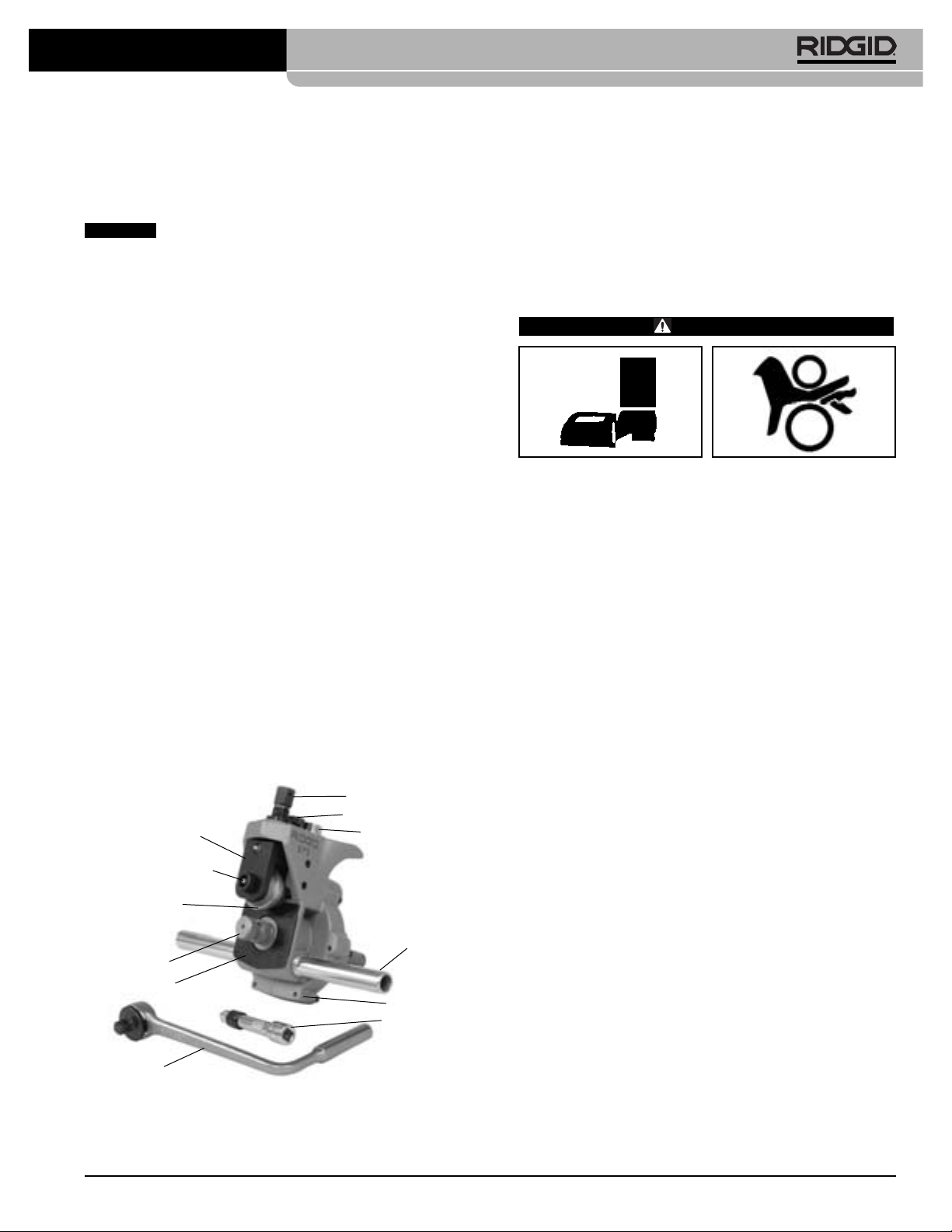
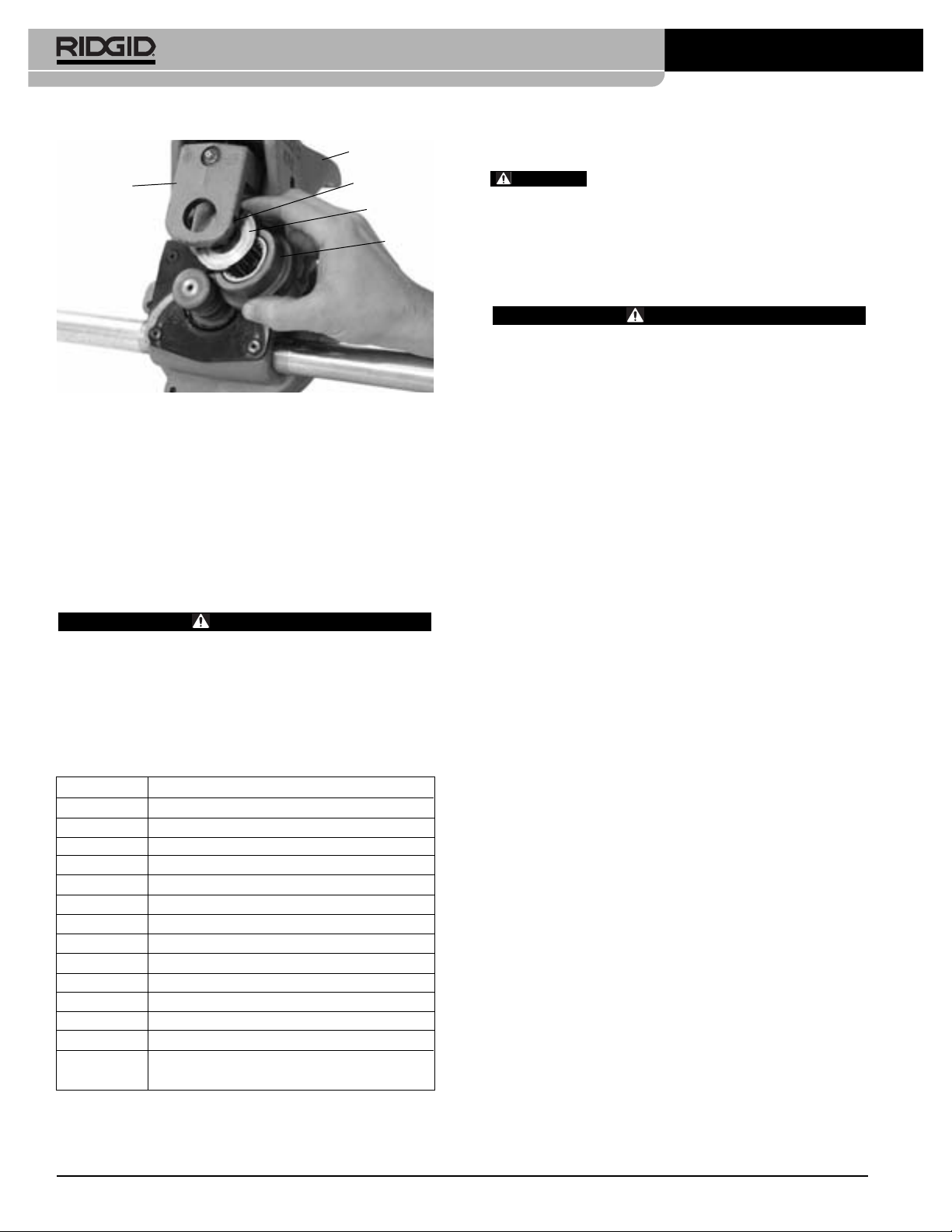
Slide Block
Groove Roll Shaft
Groove Roll
Drive Shaft
Cover Plate
Ratchet
Figure 1 – 975 Combo Roll Groover
Feedscrew
Adjusting Screw
Groove Depth
Gauge
Support Arm
Base
Extension
Ridge Tool Company 5
2. Clean any oil, grease or dirt from the roll groover,
including the carry handle, and the ratchet used to
activate the roll groover. This reduces the risk of
injury due to the groover or ratchet slipping from your
grip during use and allows easier inspection.
3. Make sure that the support arms are tight in the body
of the roll groover.
4. Inspect the roll groover for any broken, missing, misarranged or binding parts or any other condition that
may prevent the safe and normal operation. Make
sure that the groove roll and drive shaft turn freely.
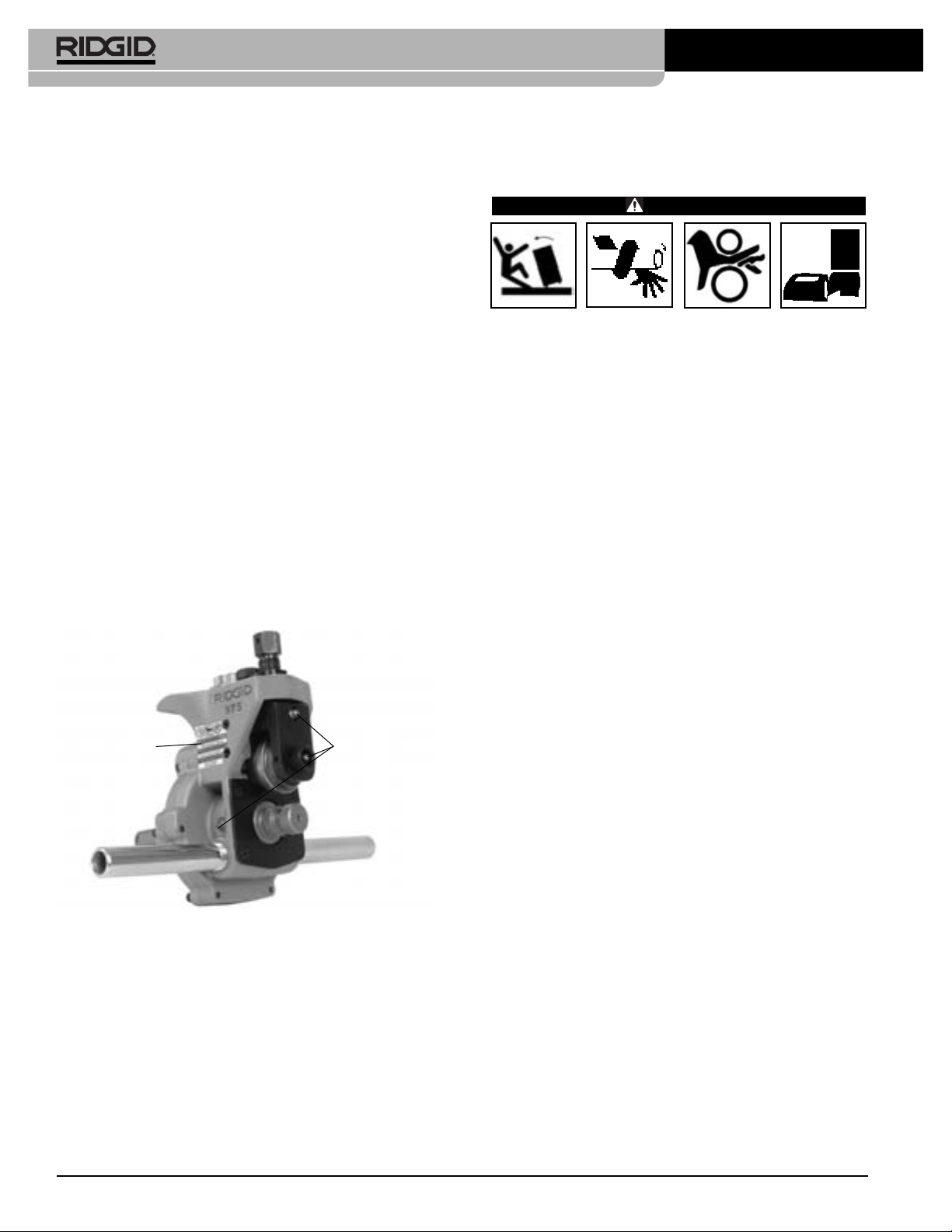
5. Check that the warning label is present and firmly
attached.
See Figure 2
for the location of the warning
label.
6. If the drive shaft knurls are dirty, clean with a wire
brush. Dirty knurls can cause pipe slippage and tracking issues during grooving.
Page 8
975 Combo Roll Groover
7. Inspect the groove roll and drive shaft for cracks,
wear or other signs of damage. Damaged groove
rolls and drive shafts can cause pipe slippage, poor
quality grooves, or cause failure during use.
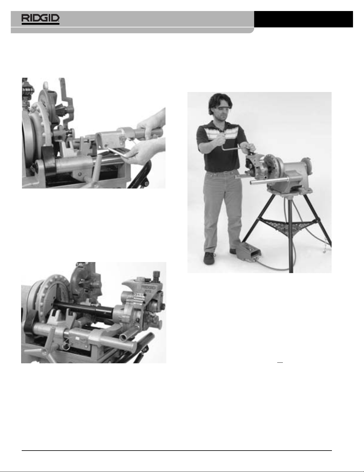
8. Inspect the ratchet and extension for proper operation.
Make sure that the ratchet operates smoothly and
consistently in both directions. Press the release button in the center of the ratchet head and install on the
feedscrew. The ratchet should firmly lock into position.
The ratchet should also lock securely into the extension and the extension should securely lock into the
manual drive square at the back of the roll groover.
This helps to prevent the ratchet and extension from
coming loose from the roll groover in use. If using a
different ratchet, wrench or extension that does not
lock to the roll groover, be aware that it could come
loose during use.
If any problems are found, do not use the machine
until the problems have been corrected.
9. Lubricate the roll groover per the maintenance instructions in this manual. Wipe any excess grease from the
roll groover.
10. If any other equipment is being used, inspect and
maintain to make sure it is functioning properly.
Machine and Work Area Set-Up
For Power Driven Applications
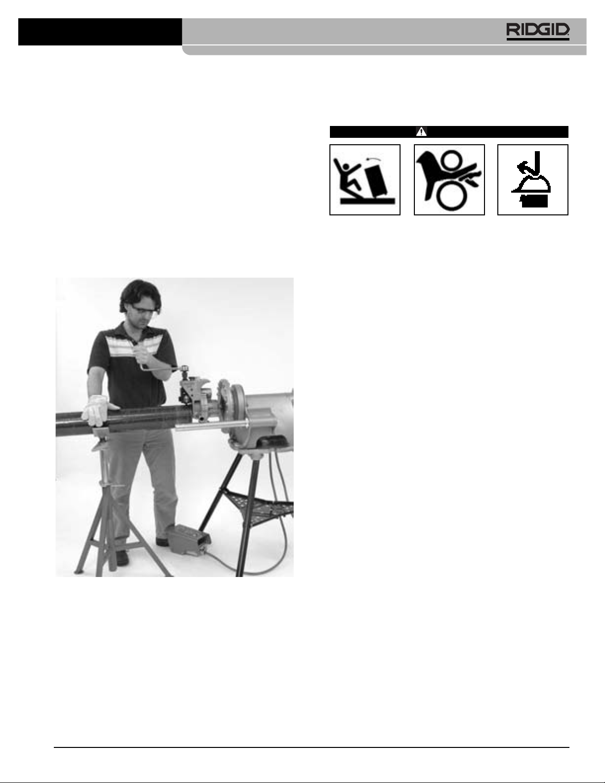
WARNING
Always wear eye protection to protect your eyes
against dirt and foreign objects. Wear steel toe
footwear to protect feet from tipping tools and
falling pipe.
Do not use this roll groover with a power drive or
threading machine that does not have a foot switch.
Never block a foot switch so that it does not control
the power drive. A foot switch provides better control by letting you shut off the power drive motor by
removing your foot. If clothing should become
caught in the machine and power is maintained to
the power drive motor, the clothing will be pulled
into the machine. This machine has high torque
and can cause the clothing to bind around your
arm or other body parts with enough force to crush
or break bones or cause striking or other injuries.
Set up the roll groover and the work area according
to these procedures to reduce the risk of injury
from electric shock, fire, machine tipping, entanglement, crushing and other causes, and prevent roll
groover damage.
Warning Label
Figure 2 – 975 Combo Roll Groover Warning Label
Grease
Fittings
1. Locate a work area that has the following:
• Adequate lighting.
• No flammable liquids, vapors or dust that may
ignite. If present, do not work in area until sources
have been identified and corrected. Power Drives
and threading machines are not explosion proof,
and can cause sparks.
• Clear, level, stable and dry location for all of the
equipment and the operator. Do not use the equipment while standing in water.
• Properly grounded electrical outlet. A three prong
or GFCI outlet may not be properly grounded. If in
doubt, have outlet inspected by a licensed electrician.
• Clear path to the electrical outlet that does not
contain any potential sources of damage to the
power cord.
2. Clean up the work area prior to setting up any equipment. Always wipe up any oil that may be present.
3. Inspect the pipe to be grooved and confirm that the
975 Combo Roll Groover is the correct tool for the job.
The 975 Combo Roll Groover is designed to groove
schedule 10 and 40 steel, aluminum, and PVC pipe in
11/4" to 6" sizes. It is also designed to groove 11/4" to 6"
Ridge Tool Company6
Page 9
1
schedule 10 and 1
/4" to 2" schedule 40 stainless
steel pipe. With a roll set change, it can be used to
groove 2" - 8" Type K, L, M and DWV copper tube.
The 975 Combo Roll Groover can be used for in
place applications (pipe that is in place or mounted in
a vise) or with a RIDGID 300 Power Drive or 300
Compact Threading Machine for powered applications
on the job site. The 975 Combo Roll Groover is not
intended for production type applications.
Roll groovers for other applications can be found
by consulting the Ridge Tool catalog, on line at
www.RIDGID.com, or by calling Ridge Tool Technical
Services at 800-519-3456.
NOTICE
Use of roll sets (groove roll and driveshaft)
on both carbon and stainless steel pipe can lead to contamination of the stainless steel material. This contamination could cause corrosion and premature pipe failure. To
prevent ferrous contamination of stainless steel pipe, use roll
sets dedicated for stainless steel roll grooving. Alternately,
a stainless steel wire brush may be used to thoroughly
clean the roll set when switching between materials.
4. Make sure the power drive/threading machine has
been inspected per it’s manual. Confirm the presence
of a foot switch and make sure that the FOR/OFF/REV switch is in the OFF position. Set up the power
drive/threading machine as directed in it’s manual.
Make sure that the machine and stand are stable and
do not wobble.
5. Fully open the chuck of the power drive/threading
machine.
6. Confirm that the 975 Combo Roll Groover has been
inspected and has the appropriate roll set installed.
975 Combo Roll Groover
Figure 3 – Mounting 975 Combo Roll Groover Into 300
Power Drive Chuck
Mounting The 975 Combo Groover Onto A
RIDGID 300 Compact Threading Machine
When using the 975 Combo Roll Groover with a 300
Compact Threading Machine, an adapter kit (Catalog
Number 67662) must be used. This adapter kit properly
positions the 975 Combo Roll Groover relative to the
threading machine and stand and to allow the complete
range of sizes to be grooved. Do not try to use the 975
Combo Groover with any other threading machine, as tipping or other issues may result.
1. Install the drive bar adapter onto the roll groover
drive shaft
flats on the roll groover drive shaft and firmly tighten.
(See Figure 4)
. Align set screws with the
Mounting The 975 Combo Groover Onto
A RIDGID 300 Power Drive
1. If the power drive to be used is equipped with a carriage or other attachments, remove them from the
power drive. Make sure the power drive support
arms are fully forward and fixed in position.
2. Place the support arms of the roll groover onto the
support arms of the power drive and the end of the roll
groover driveshaft in the chuck of the machine. Close
and tighten the power drive chuck onto the flats of the
driveshaft. Make sure that the driveshaft is centered
in the chuck. Use repeated and forceful counterclockwise spins of the speed chuck hammerwheel to
securely grip the driveshaft
(Figure 3)
.
Ridge Tool Company 7
Figure 4 – Installing Drive Bar Adapter
2. Move carriage on the 300 Compact Threading Machine as close to the machine chuck as possible.
Move the cutter, reamer and die head in to the position away from the operator, so they are out of the
way. Position reamer cone inside of die head.
Page 10
975 Combo Roll Groover
3. Place the adapter bracket over the end of rails of the
300 Compact
(as shown in Figure 5)
and lock into
place with the attached pin
Figure 5 – Installing Adapter Bracket
4. Place the 975 support arms on the arms of the
adapter bracket with the drive bar adapter in the
chuck of the machine. Close and tighten the threading
machine chuck onto the drive bar adapter. Make
sure that the drive bar is centered in the chuck. Use
repeated and forceful counterclockwise spins of the
speed chuck hammerwheel to securely grip the drive
bar.
• Control the ON/OFF action of the foot switch and
quickly release the foot switch if needed.
• Have convenient access to the roll groover, pipe
and ratchet wrench without reaching over the roll
groover.
Figure 6 – 975 Combo Roll Groover Properly Mounted
On 300 Compact Threading Machine
Completing Set Up
1. Position the foot switch so that the operator can control the power drive/threading machine, the roll
groover and the pipe to be grooved. As shown in
Figure 6
• Stand facing the roll groover with access to (on the
, the position should allow the operator to:
same side as) the FOR/OFF/REV switch.
Figure 7 – Operator Position
2. Run the power cord along the previously identified
clear path. With dry hands plug the power drive into
the properly grounded outlet. Keep all connections dry
and off the ground. If the power cord is not long
enough use an extension cord that :
• Is in good condition
• Has a three prong plug similar to that on the power
drive
• Is rated for outdoor use and contains a W or W-A in
the cord designation (i.e. SOW)
• Has sufficient wire size (14 AWG for 25' or less, 12
AWG for 25' – 50' long). Undersized wires can
overheat, melting the insulation or causing a fire or
other damage.
3. Check the power drive/threading machine to make
sure that it is operating correctly:
• Move the switch to the FOR (Forward) position.
Press and release the foot switch. Confirm that
the driveshaft rotates in a counter-clockwise direction as you face the front chuck. If the unit does not
Ridge Tool Company8
Page 11
975 Combo Roll Groover
rotate in the correct direction or the foot switch does
not control the machine operation, do not use the
machine until it has been repaired.
• Depress and hold the foot switch. Check the rotational speed of the unit. Inspect the moving parts for
misalignment, binding, odd noises or any other
unusual conditions. Release foot switch. If the rotational speed exceeds 57 rpm, do not use the unit for
roll grooving. Higher speeds may increase the risk
of injury. If unusual conditions are found, do not use
the equipment until it has been repaired.
• Move the switch to the REV (reverse) position.
Press and release the foot switch. Confirm that
the driveshaft rotates in a clockwise direction as you
face the front of the chuck. If the unit does not
rotate in the correct direction, do not use the
machine until it has been repaired.
• Move the switch to the OFF position. With dry
hands unplug the machine.
Pipe Preparation
NOTICE
follow grooved coupling manufacturer’s specific recommendations for pipe end preparation. Failure to follow the
grooved coupling manufacturer’s recommendations may
lead to an improper connection and cause leaks.
1. Cut pipe to proper length. Be aware of the minimum
lengths of pipe that can be grooved for each size of
pipe
imum length increases the risk of injury from crushed
fingers and entanglement.
Make sure pipe end is cut square and free of burrs.
Burrs can catch or cut gloves or fingers during grooving. Cut off method and large burrs can effect the
quality of the groove made and the tracking of the
Groove. Do not attempt to groove pipe that has been
cut with a torch.
These are generalized instructions. Always
(See Chart A)
. Grooving pipe shorter than min-
2. Make sure to have appropriate support available for
the pipe you are going to be grooving.
Chart A
lists
the maximum length of pipe to be grooved using a
single pipe stand. Longer lengths of pipe should be
supported with at least two pipe stands. Failure to
properly support the pipe may allow the pipe or the
pipe and machine to tip and fall. Do not groove pipe
shorter than the minimum length.
Nom. Min. Max. Nom. Min. Max.
Size Length Length Size Length Length
1 8 36 4 8 36
1
4
/
1
1
2
1
/
2 8 36 6 O.D. 10 30
1
2
2
/
3 8 36
1
2
3
/
Chart A – Minimum/Maximum Pipe Length To Be Grooved
8 36 41/
8 36 5 8 32
8 36 6 10 28
8 36
With One Stand (All Dimensions In Inches)
2
8 32
3. Place the required pipe stands in front of the roll
groover. For lengths supported by a single stand, the
stand should be placed slightly more than half the
length of the pipe from the roll groover cover plate. For
lengths of pipe requiring more than one stand, the
stands should be placed 1/4of the pipe length from the
ends of the pipe. It may be appropriate to use more
stands in some situations. Stand height should be
adjusted so that the pipe can fit over the drive roll.
4. Make sure that the groove roll has been retracted
enough to allow the pipe to be placed over the drive
shaft. If needed, turn the feedscrew counter-clockwise
to raise the groove roll.
5. Place the pipe end over the driveshaft and set the
pipe down onto the pipe stand(s). Make sure the
pipe is stable.
2. All internal/external weld beads, flash, or seams must
be ground flush at least 2" back from the end of the
pipe. Do not cut flats into gasket seat area, this could
cause leaks.
3. Remove all scale, dirt, rust and other contaminants at
least 2" back from the end of the pipe. Contaminants
can clog the drive knurls and prevent proper driving
and tracking of the pipe while grooving.
Pipe Set Up In Roll Groover
1. Confirm that the power drive switch/threading machine is in the OFF position.
Ridge Tool Company 9
Cover Plate
Figure 8 – Placing Pipe Over Driveshaft and Flush To
Cover Plate
6. Adjust pipe and pipe stands so that the end of the
pipe is flush to the roll groover cover plate and that the
inside of the pipe contacts the top of the driveshaft
Page 12
975 Combo Roll Groover
(Figure 7)
. The centerline of the pipe and the centerline of the drive shaft should be parallel to one
another. One way to do this is to level both the pipe
and the power drive/threading machine.
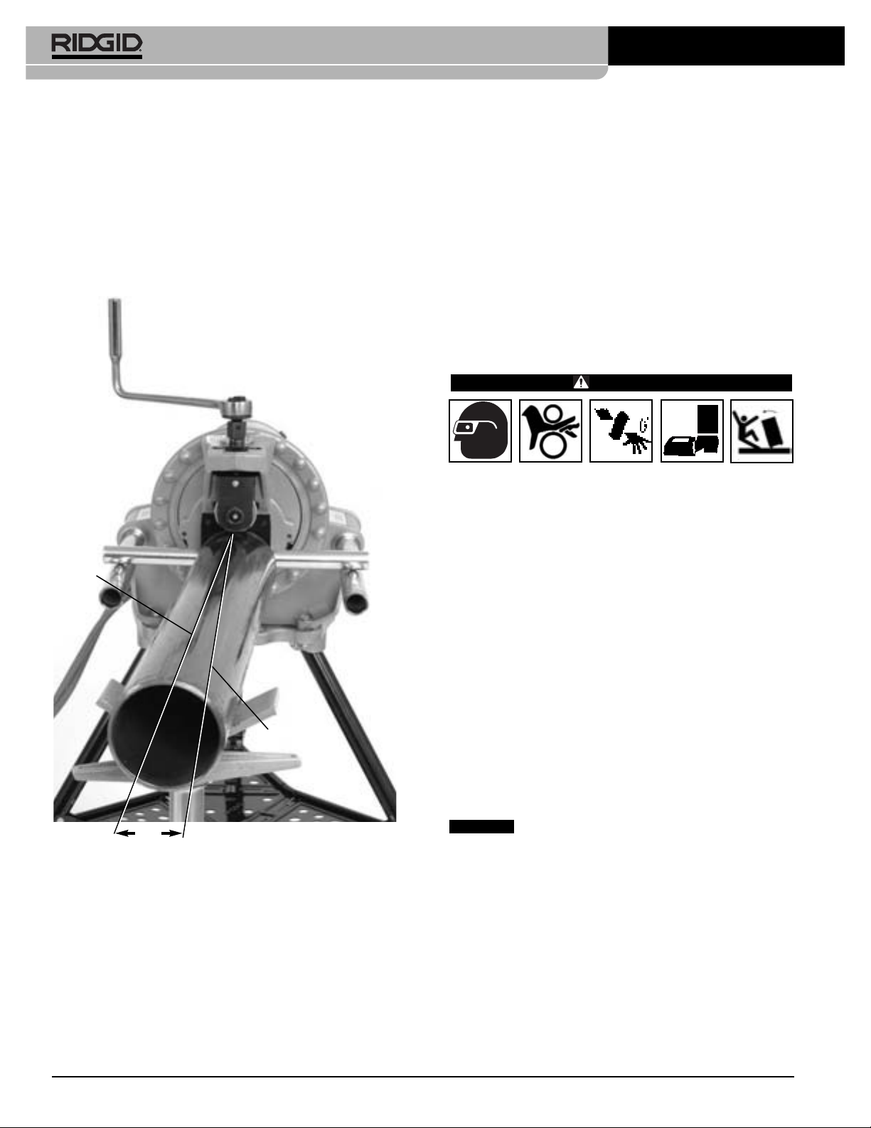
7. Slightly offset the pipe and pipe stands approximately
1
/2degree (about 1" over at 10 feet from the roll groover) towards the operator. Proper alignment of the
pipe and roll groover helps to insure proper tracking
of the pipe while grooving.
Pipe
Center
Line
(See Figure 9.)
Drive Shaft
Center Line
away from the equipment and pipe. Guards or barricades should be used to create a minimum of three
(3) feet of clearance around the power drive and
pipe. This “safety zone” prevents others from accidentally contacting the machine or pipe and causing
tipping or becoming entangled in the rotating parts.
10. With dry hands, plug the machine into the properly
grounded outlet.
Operating The 975 Combo Roll
Groover With A Power
Drive/Threading Machine
WARNING
Do not wear loose clothing when operating the roll
groover. Keep sleeves and jackets buttoned. Do
not reach across the machine or pipe. Loose clothing can become entangled in rotating parts and
cause crushing injuries.
Keep hands away from grooving rolls. Do not groove
pipes shorter than specified. Do not wear loose
fitting gloves. Fingers can be crushed between
groove rolls or between groove roll and pipe.
Keep hands away from ends of pipe. Do not reach
inside pipe. Burrs and sharp edges can catch and
cut. Fingers can be crushed between groove rolls or
between groove roll and pipe.
Always wear eye protection to protect your eyes
against dirt and foreign objects. Wear steel toe
footwear to protect feet from tipping tools and
falling pipe.
Follow operating instructions to reduce the risk of
injury from crushing, tipping, striking and other
causes.
1
/2°
Figure 9 – Offsetting The Pipe 1/2° Towards Operator
(Exaggerated)
8. Turn the feedscrew clockwise to bring the groove
roll down in contact with the pipe outside diameter,
then turn the feedscrew one quarter additional turn.
The adjusting screw may need to be loosened (turned
counter-clockwise) to allow the groove roll to contact
pipe. The pipe and roll groover should be secure to
each other at this point.
9. Evaluate the work area and determine if any barriers
are required to keep people other than the operator
Setting/Measuring The Groove Diameter
NOTICE
groove should always be performed before the first
groove of the day or when changing pipe size, schedule
or material. Groove diameter setting gauges are approximate only and the groove diameter must be measured
to confirm proper size.
1. Confirm that the equipment and pipe is properly set
up. Improper pipe preparation can effect the accurate
set up of the groove depth gauge. The groove roll
should be touching the pipe.
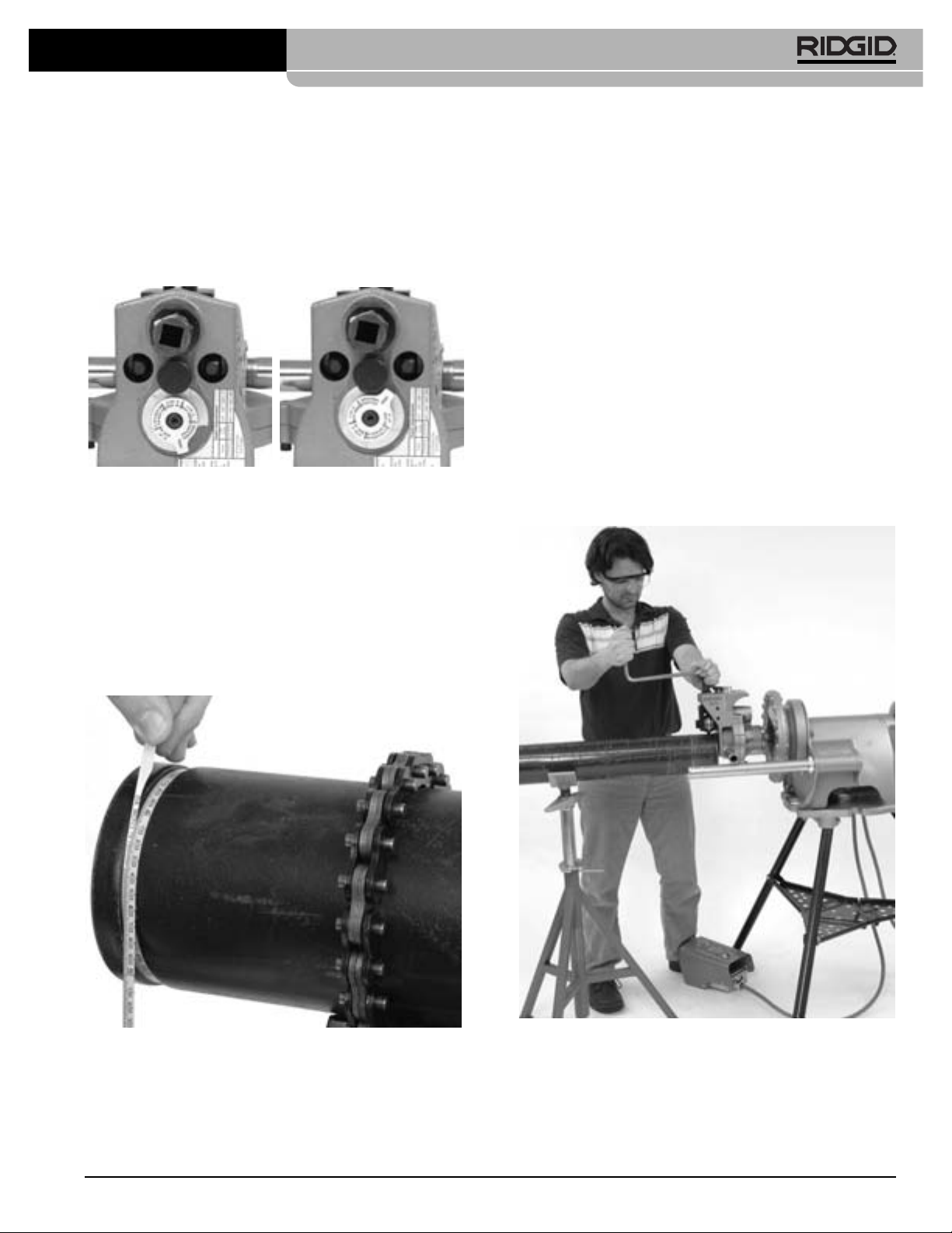
2. Adjust the groove depth gauge so that the correct
step of the gauge is under the head of the adjusting
screw
Ridge Tool Company10
Due to differing pipe characteristics, a test
(Figure 10A).
The groove depth gauge is
Page 13
975 Combo Roll Groover
designed for use with pipe.
See “Setting The Groove
Diameter For Copper Tube” for use with copper tube.
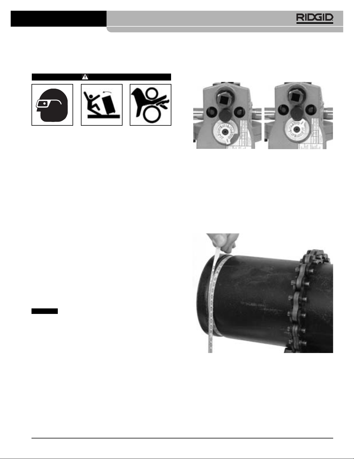
3. Turn the adjusting screw clockwise until the head
touches the step of the depth gauge. Turn the groove
depth gauge to the grooving position
(Figure 10B).
the gauge is not in the grooving position it will prevent
grooving and may be damaged.
Figure 10A – Place Correct
Step of Gauge Under
Adjusting Screw Head
4. Prepare a test groove
Figure 10B – Gauge In
Grooving Position
(follow the steps for “Forming
the Roll Groove).
5. Measure the groove diameter. The best method for
measuring groove diameter is the use of a diameter
tape
(see Accessories Section)
. Snugly wrap the
diameter tape around the pipe in the groove. Make
sure that the tape sits flat in the bottom of the groove,
and read the groove diameter.
(See Figure 11.)
diameter, the adjusting screw must be repositioned to
give the correct groove diameter.
• To increase groove diameter, turn the adjusting
screw clockwise.
If
• To decrease groove diameter, turn the adjusting
screw counter-clockwise.
• Each 1/4turn of the adjusting screw changes the
groove diameter approximately 0.02".
7. Repeat steps 4-6 until the groove diameter is within
specifications. If the groove is too large, the groover
can be adjusted and the groove made smaller. If the
groove is too small, another groove will need to be
made. Proper groove diameter is important to insure
connection performance. Out of specification grooves
could cause joint failure.
Forming The Roll Groove
1. Confirm that the equipment and pipe are properly
set up.
Figure 11 – Checking Groove Diameter With A Diameter
Tape
6. Compare the measured groove diameter to the required groove diameter as shown in
Table I or III
or as
specified by the groove fitting manufacturer. If the
measured groove is outside of the required groove
Ridge Tool Company 11
Figure 12 – Roll Groover Operating Position
2. Assume a proper operating position. Position the
power drive foot switch so that the operator can control the power drive, the roll groover and the pipe to be
grooved. As shown in
Figure 12
, the position should
allow the operator to:
Page 14

975 Combo Roll Groover
• Stand facing the roll groover with access to (on
the same side as) the FOR/OFF/REV switch.
• Control the ON/OFF action of the foot switch and
quickly release the foot switch if needed.
• Have convenient access to the groover and ratchet wrench without reaching over the roll groover.
• Place right hand on pipe being grooved if needed.
• Have good footing and proper balance.
3. Move the FOR/OFF/REV switch to the REV (reverse
position). Do not run the 975 Combo Roll Groover
in the FOR (forward). Because of the design of the
975 Combo Roll Groover, this will cause the pipe
to “spiral” out of the roll groove rolls and may
allow the pipe to fall.
4. Place one hand on the on the head of the ratchet/top
of the feedscrew and the other hand on the end of the
ratchet.
5. Press the foot switch to start the power drive. Watch
the pipe rotate and be sure that the face of the pipe
stays in contact with the cover plate of the roll groover.
If the pipe starts to move away from the roll groover
cover plate, release the foot switch to prevent the pipe
from spiraling off and falling. If needed, re-set up the
(see Pipe Set Up Section)
pipe
. If the pipe end is deformed, it will need to be cut off and a new groove
prepared.
6. As the pipe completes a full rotation, tighten the feedscrew another 1/4turn. Continue to monitor the pipe
end to make sure that it is in contact with the cover
plate. Do not tighten the feedscrew more than 1/
turn per pipe rotation. Aggressive tightening of the
feedscrew can cause excessive groove flare or cause
the pipe to spiral off the drive shaft.
7. Continue tightening the feedscrew
1
/4turn per pipe revolution until the head of the adjusting screw stops
against the top of the roll groover. Do not continue
tightening the feedscrew after the adjusting screw
reaches the top of the roll groover, this can damage
the adjusting screw. Allow the pipe to rotate at least
two more full rotations in this position to insure uniform
groove depth.
8. Release the foot switch and move the FOR/OFF/REV
switch to the OFF position.
9. Turn the feedscrew counter-clockwise and raise the
groove roll so that the pipe can be removed from
the machine.
10. Inspect the groove.
• Make sure that the groove is fully formed.
• Check the groove diameter and make sure it is
within specification.
• Check any other items required by the fitting manufacturer.
If any problems are found, the groove cannot be used.
Setting The Groove Diameter For
Copper Tubing
When using the 975 Combo Roll Groover for copper
tube, the groove depth gauge on the groover cannot be
used. It will give incorrect groove diameters.
1. Turn the feedscrew clockwise to bring the groove
roll down in contact with the pipe outside diameter,
then turn the feedscrew one quarter additional turn.
The adjusting screw may need to be loosened (turned
counter-clockwise) to allow the groove roll to contact
pipe. The pipe and roll groover should be secure to
each other at this point.
2. Make sure the groove depth gauge is in the grooving
position.
(Figure 10B)
3. Turn the adjusting screw until it is flush with the top
plate of the groover.
4. Find the diameter and type of pipe to be grooved on
Table B and back the adjusting screw off the top
plate the corresponding number of turns. For example, for 4" Sch. L copper, back the adjustment screw
11/4turns.
Depth Adjustment for Roll Grooving Copper Tubing
4
(Adjusting Screw Turns)
Dia. K L M DWV
7
2-2.5"
3" 11/
4" 11/
5" 11/
6" 113/
8" 21/
8
/
16
4
2
16
2
Chart B – Depth Adjustment for Roll Grooving Copper
Tubing
5.
Go to step 4 of “Setting/Measuring The Groove
11/
11/
11/
13/
23/
7
8
/
16
4
2
4
8
11/
11/
11/
13/
21/
5
8
/
16
4
2
4
8
11/
11/
11/
13/
21/
5
8
/
16
8
2
4
8
Diameter”.
975 Combo Roll Groover Tracking Tips
The main issue users encounter when roll grooving is the
pipe “spiraling” or “walking off” the driveshaft or not “tracking” properly. For good tracking, it is important that all of
the instructions are followed. If, even after following all
instructions, the pipe will not properly track, there are
several other options to improve tracking.
Ridge Tool Company12
Page 15
975 Combo Roll Groover
• Slightly increase the offset of the pipe towards the
operator (increase from 1/2degree to 1 degree)
(See
Figure 9).
• The operator may need to apply slight force on the
pipe while grooving to maintain tracking. This is usually only needed on shorter sections of pipe. To do
this, the operator should wear a leather glove in
good condition and cup their hand around the middle
of the pipe as shown in
Figure 13
. This may require
that the stand to which the power drive/threading
machine is mounted be fixed to the floor to prevent
movement during grooving. To prevent crushing
injuries, keep hand away from the groove roll and the
ends of the pipe, and do not groove pipe shorter
that recommended.
Machine and Work Area Set-Up
For In Place Applications
WARNING
Always wear eye protection to protect your eyes
against dirt and foreign objects. Wear steel toe
footwear to protect feet from tipping and falling
pipe and tools. When working in place, wear a hard
hat.
Set up roll groover and work area according to
these procedures to reduce the risk of injury from
machine tipping, crushing and other causes, and
prevent roll groover damage.
1. Locate a work area that has the following:
• Adequate lighting.
• No flammable liquids, vapors or dust that may ignite.
If present, do not work in area until sources have
been identified and corrected.
• Clear, level, stable and dry location with adequate
space for all of the equipment and the operator.
2. Clean up the work area prior to setting up any equipment. Always wipe up any oil that may be present.
Figure 13 – Applying Force To Pipe While Grooving To
• Additionally, see the
Maintain Tracking
Troubleshooting Section
for a
complete list of reasons for and solutions to tracking
issues.
3. Inspect the pipe to be grooved and confirm that the
975 Combo Roll Groover is the correct tool for the job.
The 975 Combo Roll Groover is designed to groove
schedule 10 and 40 steel, aluminum, and PVC pipe in
11/4" to 6" sizes. It is also designed to groove 11/4" to 6"
schedule 10 and 11/4" to 2" schedule 40 stainless
steel pipe. With a roll set change, it can be used to
groove 2" - 8" Type K, L, M and DWV copper tube.
The 975 Combo Roll Groover can be used for in
place applications (pipe that is in place or mounted in
a vise) or with a RIDGID 300 Power Drive or 300
Compact Threading Machine for powered applications
on the job site. The 975 Combo Roll Groover is not
intended for production type applications.
4. When grooving in place, make sure that there will be
enough space for the 975 Combo Roll Groover to fit
and be operated. The roll groover will orbit around the
solidly mounted pipe and requires:
• A minimum of 61/2" clear space around the pipe to
the be grooved
• A minimum of 21/2" pipe extending past an obstruc-
tion such as a wall
Ridge Tool Company 13
Page 16

975 Combo Roll Groover
• A minimum opening of 91/2" to fit the roll groover
onto the pipe
Roll groovers for other applications can be found
by consulting the Ridge Tool catalog, on line at
www.RIDGID.com, or by calling Ridge Tool Technical Services at 800-519-3456.
NOTICE
Use of roll sets (groove roll and driveshaft) on
both carbon and stainless steel pipe can lead to contamination of the stainless steel material. This contamination could cause corrosion and premature pipe failure.
To prevent ferrous contamination of stainless steel pipe,
use roll sets dedicated for stainless steel roll grooving.
Alternately, a stainless steel wire brush may be used to
thoroughly clean the roll set when switching between
materials.
Pipe Preparation
NOTICE
follow grooved coupling manufacturer’s specific recommendations for pipe end preparation. Failure to follow
the grooved coupling manufacturer’s recommendations
may lead to an improper connection and cause leaks.
1. If grooving in place on an existing piping, make sure
that the system has been depressurized and emptied
of contents. Know what the contents are and any
hazards associated with them.
2. Cut pipe to proper length.
Make sure pipe end is cut square and free of burrs.
Burrs can catch or cut gloves or fingers during grooving. Cut off method and large burrs can effect the
quality of the groove made and the tracking of the
Groove. Do not attempt to groove pipe that has been
cut with a torch.
These are generalized instructions. Always
Mounting The Roll Groover To The Pipe
1. Confirm that the 975 Combo Roll Groover has been
inspected and has the appropriate roll set installed.
Make sure that the support arms are tight in the body
of the roll groover or remove them completely for
better access in tight spaces. Next, install the ratchet
into the feedscrew and install the extension into the
manual drive square at the back of the roll groover.
Make sure both the ratchet and extension are securely installed.
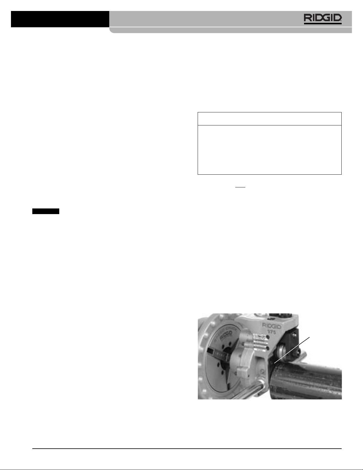
2. Make sure that there is enough space between the
groove roll and drive shaft for the pipe wall. If needed,
turn the feedscrew counter-clockwise to retract the
groove roll.
3. Securely grasp the roll groover. Do not lift with the
ratchet. Place the driveshaft into the pipe and make
sure that the cover plate is tight to the end of the pipe
(Figure 14)
roll into contact with the outside of the pipe. Once the
feedscrew is hand tight, use the ratchet to tighten the
feedscrew an additional 1/4turn. Confirm that the roll
groover is securely attached to the pipe and the
cover plate is flush to the end of the pipe. If not,
repeat procedure. Always make sure groover is
secure when used in place to prevent it from falling.
. Tighten the feedscrew to bring the groove
3. All internal/external weld beads, flash, or seams must
be ground flush at least 2" back from the end of the
pipe. Do not cut flats into gasket seat area, this could
cause leaks.
4. Remove all scale, dirt, rust and other contaminants at
least 2" back from the end of the pipe. Contaminants
can clog the drive knurls and prevent proper driving
and tracking of the pipe while grooving.
5. Make sure that the pipe to be grooved is solidly
mounted. The pipe must be able to withstand the
weight of the roll groover (28 pounds), and the force
and torque required for grooving without moving.
For pipe that is in place, it may make sense to remove
the pipe and groove at a pipe vise. In other cases, it
may be necessary to add other temporary or permanent pipe supports. When using a pipe vise, make
sure that it is secure and will not tip during use. For
longer lengths of pipe, use appropriate pipe stands to
support the extra length.
Ridge Tool Company14
Cover Plate
Figure 14 – Holding the Roll Groover In Place While
Tightening the Feedscrew
Page 17
975 Combo Roll Groover
Operating The 975 Combo Roll
Groover In Place
WARNING
Only drive manually when used for in place applications. Do not use powered devices (such as drills
or impact tools) to drive the roll groover when used
in place. Use of powered devices can damage the
groover and increase the risk of injury.
Do not wear loose clothing when operating the roll
groover. Keep sleeves and jackets buttoned. Do
not reach across the machine or pipe. Loose clothing can become entangled in rotating parts and
cause crushing injuries.
Keep hands away from grooving rolls. Do not groove
pipes shorter than specified. Do not wear loose fitting gloves. Fingers can be crushed between groove
rolls or between groove roll and pipe.
Keep hands away from ends of pipe. Do not reach
inside pipe. Burrs and sharp edges can catch and
cut. Fingers can be crushed between groove rolls or
between groove roll and pipe.
Always wear eye protection to protect your eyes
against dirt and foreign objects. Wear steel toe footwear to protect feet from tipping tools and falling
pipe. When working in place, wear a hard hat.
Follow operating instructions to reduce the risk of
injury from crushing, tipping, striking and other
causes.
touches the step of the depth gauge. Turn the groove
depth gauge to the grooving position
(Figure 15B)
gauge is not in the grooving position it will prevent
grooving and may be damaged.
Figure 15A – Place Correct
Step of Gauge Under
Adjusting Screw Head
4. Prepare a test groove (
the Roll Groove)
.
Figure 15B – Gauge In
Grooving Position
follow the steps for “Forming
5. Measure the groove diameter. The best method for
measuring groove diameter is the use of a diameter
tape
(See Accessories Section)
. Snugly wrap the
diameter tape around the pipe in the groove. Make
sure that the tape sits flat in the bottom of the groove,
and read the groove diameter
(See Figure 16)
.
. If
Setting/Measuring The Groove Diameter
NOTICE
groove should always be performed before the first
groove of the day or when changing pipe size, schedule
or material. Groove diameter setting gauges are approximate only and the groove diameter must be measured to
confirm proper size.
1. Confirm that the equipment and pipe are properly
set up. Improper pipe preparation can effect the
accurate set up of the groove depth gauge. The
groove roll should be touching the pipe.
2. Adjust the groove depth gauge so that the correct step
of the gauge is under the head of the adjusting screw
(Figure 15A).
use with pipe.
Copper Tube” for use with copper tube
3. Turn the adjusting screw clockwise until the head
Due to differing pipe characteristics, a test
The groove depth gauge is designed for
See “Setting The Groove Diameter For
.
Ridge Tool Company 15
Figure 16 – Measuring The Groove Diameter With A
Diameter Tape
6. Compare the measured groove diameter to the required groove diameter as shown in
Table I or III
or as
specified by the groove fitting manufacturer. If the
measured groove is outside of the required groove
diameter, the adjusting screw must be repositioned to
give the correct groove diameter.
• To increase groove diameter, turn the adjusting
screw clockwise.
Page 18
975 Combo Roll Groover
• To decrease groove diameter, turn the adjusting
screw counter-clockwise.
• Each 1/4turn of the adjusting screw changes the
groove diameter approximately 0.02".
7. Repeat steps 4-6 until the groove diameter is within
specifications. If the first groove is too large, the
Groove can be adjusted and the groove made smaller. If the groove is too small, another groove will
need to be made. Proper groove diameter is important
to insure connection performance. Out of specification
grooves could cause joint failure.
Forming The Roll Groove
1. Confirm that the equipment and pipe are properly
set up.
2. Assume a proper operating position. Make sure that
your footing is good and you are well balanced.
3. Make sure that the feedscrew has been tightened 1/
turn.
4. Remove the ratchet from the feedscrew and securely install in the extension. (In close quarters applications, the extension does not need to be used.)
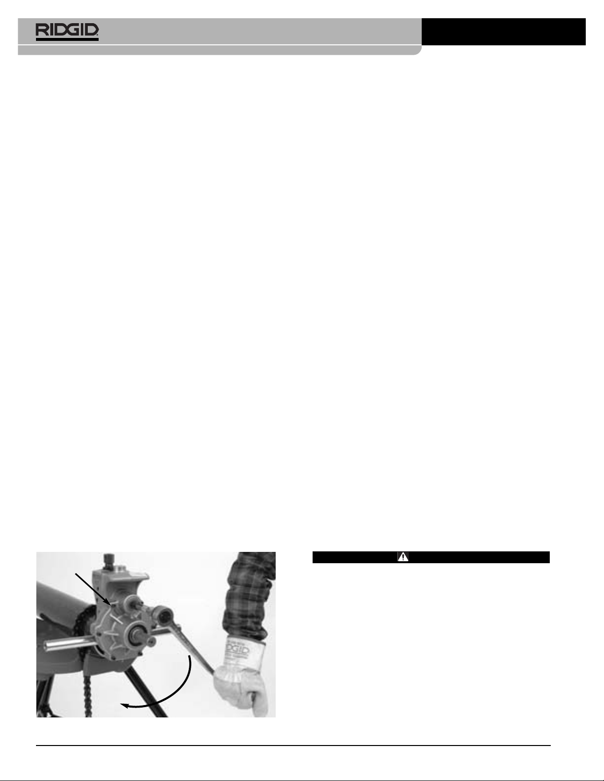
5. Turn the ratchet clockwise as viewed from the back of
the roll groover (this will match the arrows cast into the
back of the roll groover,
groover rotate and be sure that the cover plate of the
roll groover stays in contact with the end of the pipe.
If the roll groover starts to move away from the pipe
end, stop rotating the ratchet to prevent the roll
groover from spiraling off the pipe end and falling.
The roll groover support arms can be pushed on to
help bring the cover plate back in contact with the pipe
end. If needed, re-mount the roll groover to the pipe.
(see “Mounting Roll Groover to Pipe” section)
pipe end is deformed, it will need to be cut off and a
new groove prepared.
see Figure 17
). Watch the
. If the
6. Continue rotating the ratchet until the roll groover
completes at least a full rotation around the pipe.
Remove the ratchet from the extension and attach to
the feedscrew. Tighten the feedscrew another 1/
4
turn. Remove the ratchet from the feedscrew and
securely attach to the extension. Do not tighten the
feedscrew more than 1/4turn per pipe rotation. Aggressive tightening of the feedscrew can cause excessive groove flare and can cause the roll groover to
walk off the pipe. Continue rotating the ratchet to
drive the roll groover around the pipe while monitoring
the position of the cover plate to the end of the pipe.
7. Continue tightening the feedscrew 1/4turn per groove
revolution around pipe until the head of the adjusting
screw stops against the top of the roll groover. Do not
continue tightening the feedscrew after the adjusting
screw reaches the top of the roll groover, this can
damage the adjusting screw. Rotate the roll groover
4
at least two more full rotations around the pipe after
the adjusting screw reaches the top of the roll groover
to insure uniform groove depth.
8. Move the ratchet to the feedscrew. Securely grasp the
roll groover. Turn the feedscrew counter-clockwise
and retract the groove roll so that the roll groover can
be removed from the pipe. Do not drop the roll
groover.
9. Inspect the groove.
• Make sure that the groove is fully formed.
• Check the groove diameter and make sure it is
within specification.
• Check any other items required by the fitting man-
ufacturer.
If any problems are found, the groove cannot be used.
Maintenance Instructions
Turn
Figure 17 – Turning the Ratchet in the Direction of the
Arrows
WARNING
Make sure the power drive switch is in the OFF
position and the unplugged before performing any
maintenance or making any adjustments.
Lubrication
Lubricate the 975 Combo Roll Groover with a good general purpose grease once a month.
• Grease fittings are located on the side of the oper-
ator’s side of the base, the front of the slide block,
and the end of the groove roll shaft
Add grease until a small amount is pushed out.
• Apply a light coat of grease to the feedscrew.
Ridge Tool Company16
(See Figure 2).
Page 19
975 Combo Roll Groover
• The gear box of the 975 Combo Roll Groover is
greased for life and does not require the addition of
any grease unless the gear box is opened.
See Inspection Section for other information on maintenance.
Cleaning
Clean the driveshaft knurls with a wire brush on a daily
basis or more often if needed.
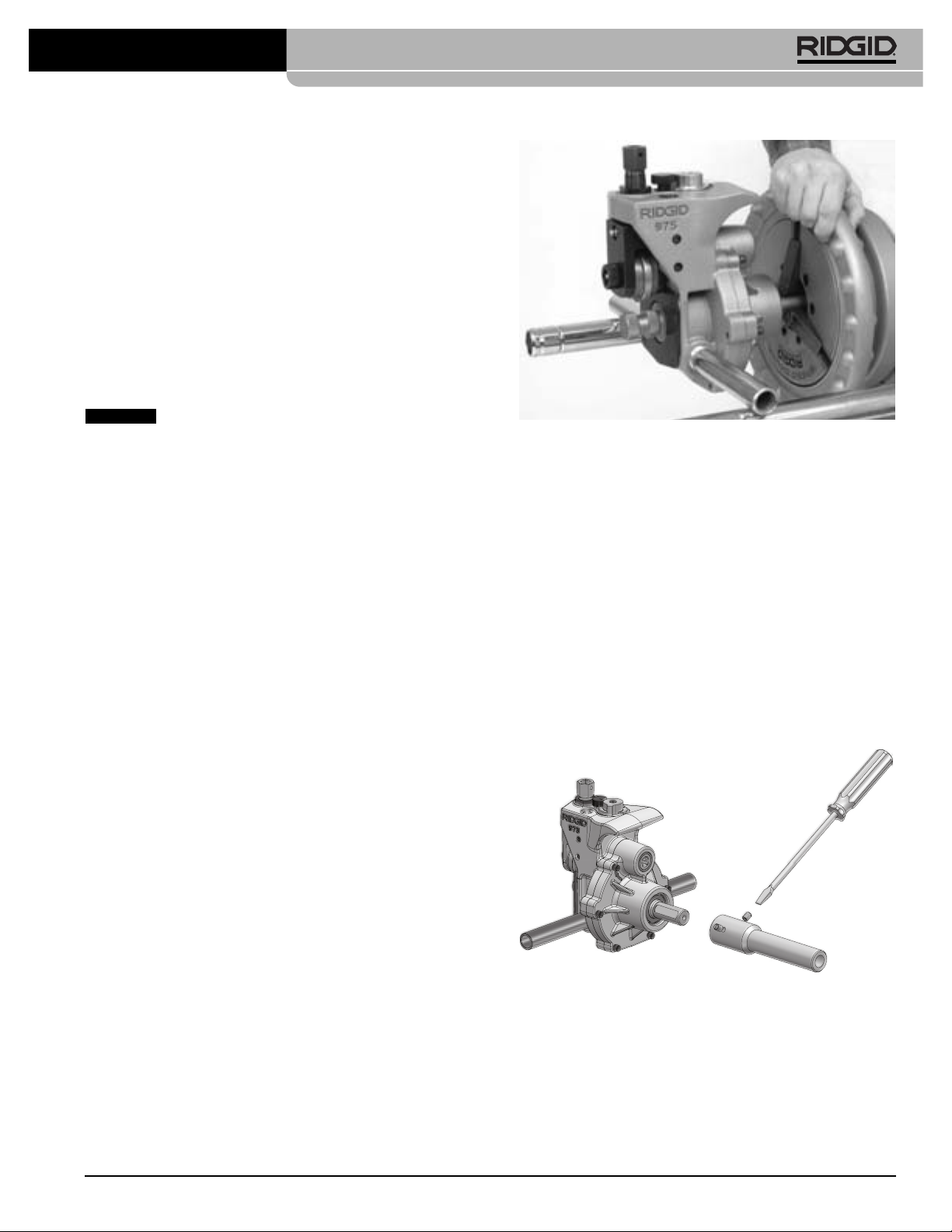
Changing Roll Sets
NOTICE
sure drive and groove roll markings match. Mismatched
parts can make improper grooves and cause leaks.
Remove the roll groover from the power drive or threading machine and place on a stable work bench.
Required Tools:
•
•3/32" Hex Wrench
• .070" External Retaining Ring Pliers
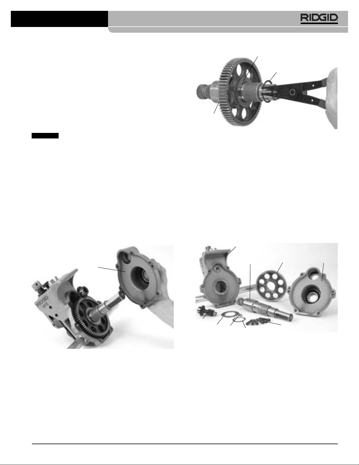
Removing and Installing Drive Roll
1. Remove 6 screws that hold rear cover to the housing.
2. Remove the rear cover
When changing roll set parts, always make
3
/8" Hex Wrench
(See Figure 18)
.
Gear
Retaining Ring
Thrust
Washer
Figure 19 – Removing Retaining Ring
6. Remove key and then thrust washer.
7. Slide thrust washer onto new driveshaft.
8. Insert key and install gear.
9. Install retaining ring into driveshaft groove.
10. Place driveshaft assembly into main housing.
11. Grease from the gearbox may have been lost during
the driveshaft change. Make sure the bearings and
gear teeth are coated sufficiently with a good general purpose grease.
12. Insert pinion and reinstall rear cover. Tighten screws
to 12-16 ft*lbs of torque.
Main Housing
Rear Cover
Figure 18 – Removing Rear Cover
3. Remove pinion.
4. Remove the driveshaft assembly out of the back of
the 975 Roll Groover.
5. Remove retaining ring from driveshaft and slide gear
off.
(See Figure 19.)
Driveshaft
Pinion
Thrust
Washer
Figure 20 – 975 Combo Roll Groover Parts Diagram
Key
Retaining
Ring
Gear
Screws
Rear Cover
Removing and Installing Groove Roll
1. Remove the setscrew that holds the groove roll shaft
in place.
2. Pull the groove roll shaft out of the slide block and
remove the groove roll and thrust washer.
3. Insert the thrust washer and new groove roll into the
slide block. Ensure that the internal retaining ring in
the groove roll is closest to the main housing, and that
the groove roll is between the thrust washer and
main housing.
Ridge Tool Company 17
Page 20
975 Combo Roll Groover
Main Housing
Slide
Block
Figure 21
Set Screw
Thrust
Washer
Groove
Roll
4. Replace the groove roll shaft and the set screw.
5. Visually inspect the alignment between the groove roll
and the drive roll. If they are not aligned, check orientation of groove roll and thrust washer.
6. Grease as directed in Lubrication Section of manual.
Accessories
WARNING
The following RIDGID products have been designed
to function with the 975 Combo Roll Groover. Other
accessories suitable for use with other tools may be
hazardous when used on the 975 Combo Roll
Groover. To reduce the risk of serious injury, only
use accessories specifically designed and recommended for use with the 975 Combo Roll Groover,
such as those listed in the chart.
Machine Storage
WARNING
out of reach of children and people unfamiliar with roll
groover equipment. This tool can cause serious injury in
the hands of untrained users.
Store the tool in a locked area that is
Service and Repair
WARNING
Improper service or repair can make machine
unsafe to operate.
The “Maintenance Instructions” will take care of most of
the service needs of this machine. Any problems not
addressed by this section should only be handled by an
authorized RIDGID service technician.
Tool should be taken to a RIDGID Independent Authorized Service Center or returned to the factory.
When servicing this machine, only identical replacement
parts should be used. Use of other parts may create a risk
of serious injury.
If you have any questions regarding the service or repair
of this machine, call or write to:
Ridge Tool Company
Technical Service Department
400 Clark Street
Elyria, Ohio 44035-6001
Tel: (800) 519-3456
E-mail: TechServices@ridgid.com
For name and address of your nearest Independent
Authorized Service Center, contact the Ridge Tool Company at (800) 519-3456 or www.RIDGID.com
Cat. Number Description
41855 300 Power Drive, 115V 25-60Hz 38RPM
75075 300 Power Drive, 115V 23-60Hz 57RPM
42360 1206 Stand for 300 Power Drive
66947 300 Compact, 115V 50/60Hz 38RPM
73447 300 Compact, 115V 50/60Hz 52RPM
67662 Adapter Bracket for 300 Compact
67657 250 Folding Wheel Stand for 300 Compact
72037 460 Portable TRISTAND Chain Vise
56662 VJ-99 VHead High Pipe Stand
76822 Inch Diameter Tape
76827 Metric Diameter Tape
30708 Extension,
30703 Ratchet,
32833 Groove and Drive Rolls for 2" - 8" Copper
Tube Type K, L, M and DWV
1
/2" Drive, Locking
1
/2" Drive With 90° bend
Ridge Tool Company18
Page 21

975 Combo Roll Groover
Table I. Standard Roll Groove Specifications For Pipe of IPS Dimensions
NOTE! All Dimensions are in Inches.
NOM. PIPE MIN. GASKET GROOVE GROOVE NOM.
PIPE DIAMETER WALL SEAT WIDTH DIAMETER GROOVE
SIZE O.D. TOL. THK. +.015/-.030 +.030/-.015 O.D. TOL. DEPTH (Ref.) (2)
1
4
1
/
1.660 +.016 .065 .625 .344 1.535 +.000 .063
-.016 -.015
1
2
1
/
1.900 +.016 .065 .625 .344 1.775 +.000 .063
-.016 -.015
(1)
2
2.375
+
.024 .065 .625 .344 2.250 +.000 .063
-.016 -.015
1
(1)
2
2
/
2.875
+
.029 .083 .625 .344 2.720 +.000 .078
-.016 -.015
(1)
3
3.50
+
.030 .083 .625 .344 3.344 +.000 .078
-.018 -.015
1
(1)
2
3
/
4.00
+
030 .083 .625 .344 3.834 +.000 .083
-.018 -.015
(1)
4
4.50
+
.035 .083 .625 .344 4.334 +.000 .083
-.020 -.015
(1)
5
5.563
+
.056 .109 .625 .344 5.395 +.000 .084
-.022 -.015
(1)
6
6.625
+
.050 .109 .625 .344 6.455 +.000 .085
-.024 -.015
(1)As per AWWA C606-06
(2)Nominal Groove Depth is provided as a reference dimension only. Do not use groove depth to determine acceptability of a groove.
TA B C D
Table II. Pipe Maximum and Minimum Wall Thickness
NOTE! All Dimensions are in Inches.
CARBON STEEL OR STAINLESS STEEL
ALUMINUM PIPE OR TUBE PIPE OR TUBE PVC PIPE
Pipe Size
1
1
/4" .065 .140 .065 .140 .140 .140
1
1
/2" .065 .145 .065 .145 .145 .200
2" .065 .154 .065 .154 .154 .154
1
2
/2" .083 .203 .083 .188 .203 .276
3" .083 .216 .083 .188 .216 .300
1
3
/2" .083 .226 .083 .188 .226 .300
4" .083 .237 .083 .188 .237 .300
5" .109 .258 .109 .188 .258 .300
6" .109 .280 .109 .188 .280 .300
Wall Thickness Wall Thickness Wall Thickness
Min. Max. Min.
Max. Min. Max.
Ridge Tool Company 19
Page 22

975 Combo Roll Groover
Table III. Copper Roll Groove Specifications
1 2 345678
AB CDT
Nom. Tubing Outside Gasket Groove Groove Groove Min. Max.
Size Diameter O.D. Seat Width Dia. Depth Allow. Allow.
Inches A +.03 +.00 Ref.
Basic Tolerance ±0.03 –.000 –.02 Thick. Dia.
2" 2.125 ±0.002 0.610 0.300 2.029 0.048 DWV 2.220
21/2" 2.625 ±0.002 0.610 0.300 2.525 0.050 0.065 2.720
3" 3.125 ±0.002 0.610 0.300 3.025 0.050 DWV 3.220
4" 4.125 ±0.002 0.610 0.300 4.019 0.053 DWV 4.220
5" 5.125 ±0.002 0.610 0.300 5.019 0.053 DWV 5.220
6" 6.125 ±0.002 0.610 0.300 5.999 0.063 DWV 6.220
8" 8.125 +0.002/-0.004 0.610 0.300 7.959 0.083 DWV 8.220
1. Nominal Groove Depth is provided as a reference dimension. Do not use groove depth to determine groove acceptability.
1
Wall Flare
Troubleshooting
SYMPTOM POSSIBLE REASONS SOLUTION
Roll groove too narrow or
too wide.
Rolled groove not perpendicular to pipe axis.
Pipe will not track while
grooving/Groover will not
track on pipe while grooving.
Pipe flared at grooved end.
Grooving roll and/or driving shaft worn.
Pipe length not straight.
Pipe end not square with pipe axis.
Pipe and drive shaft not parallel.
Pipe axis not offset 1/2degree from driving roll axis.
Driving roll knurl plugged or worn flat.
Feedscrew not tight.
Turning ratchet wrong direction.
Inside of pipe has too much scale.
Excessive weld seam.
Not applying pressure to pipe.
Pipe end not square/deburr.
Feedscrew too tight.
Pipe and drive shaft not parallel.
Feedscrew too tight.
Replace grooving roll and/or drive shaft.
Use straight pipe.
Cut pipe end square.
Adjust stand to make pipe parallel.
Offset pipe 1/2degree.
Clean or replace drive roll.
Tighten feedscrew with ratchet for every
revolution as per directions.
Turn ratchet in proper direction.
Clean inside of pipe.
Grind weld seam flush 2" from end of pipe.
Apply pressure to pipe.
Properly prep end of pipe.
Only advance feedscrew in 1/4turn increments.
Adjust stand to make pipe parallel.
Only advance feedscrew 1/4 turn.
(See Figure 10.)
Ridge Tool Company20
Page 23

975 Combo Roll Groover
Troubleshooting
(continued)
SYMPTOM POSSIBLE REASONS SOLUTION
Pipe drifts back and forth
on driving roll axis while
grooving.
Pipe rocks from side to
side on driving roll while
grooving.
Groover will not roll
groove in pipe.
Groover will not roll
groove to required
diameter.
Pipe length not straight.
Pipe end not square with pipe axis.
Pipe stand is too close to end of pipe.
Pipe end flattened or damaged.
Hard spots in pipe material or weld seams harder
than pipe.
Grooving roll feed rate too slow.
Power drive speed exceeds 57 RPM.
Pipe supports stand not in correct location.
Maximum pipe wall thickness exceeded.
Pipe material too hard.
Adjustment screw not set.
Power drive does not supply required minimum
torque.
Maximum pipe diameter tolerance exceeded.
Depth adjustment screw not set correctly.
Pipe too hard.
Use straight pipe.
Cut pipe end square.
Move pipe stand in to match set-up Instructions.
Cut off damaged pipe end.
Use different pipe.
Feed grooving roll into pipe faster.
Reduce speed to 57 RPM.
Position pipe stand rollers correctly.
Check pipe capacity chart.
Replace pipe.
Set depth.
Use RIDGID No. 300, 38-RPM Power Drive.
Use correct diameter pipe.
Adjust depth setting.
Use different pipe.
Pipe slips on driving roll.
Groover will not rotate
pipe while grooving.
Pipe rises or tends to tip
Groover over backwards.
Grooving roll feed rate too slow.
Driving roll knurls plugged with metal or worn flat.
Power drive does not supply minimum required
torque.
Chuck not closed on drive shaft flats.
Pipe support stand not properly set up.
Feed grooving roll into pipe faster.
Clean or replace driving roll.
Use RIDGID No. 300, 38 RPM Power Drive.
Close chuck.
Properly set up stands.
Ridge Tool Company 21
Page 24

975 Combo Roll Groover
Ridge Tool Company22
Page 25

Rainureuse à galets mixte
975
AVERTISSEMENT
Lisez soigneusement ce manuel
avant d’utiliser l’appareil. Le
manque d’assimilation ou le nonrespect des consignes ci-devant
augmenteraient les risques de
choc électrique, d’incendie et/ou
de blessure corporelle grave.
Page 26

Rainureuse à galets mixte modèle 975
Table des matières
Symboles de sécurité ................................................................................................................................................25
Consignes générales de sécurité
Sécurité des lieux......................................................................................................................................................25
Sécurité électrique....................................................................................................................................................25
Sécurité individuelle..................................................................................................................................................26
Utilisation et entretien de l’appareil ..........................................................................................................................26
Service après-vente..................................................................................................................................................27
Consignes de sécurité spécifiques
Sécurité de la rainureuse..........................................................................................................................................27
Sécurité de la rainureuse sur système d’entraînement ou fileteuse ........................................................................27
Sécurité de la rainureuse sur chantier......................................................................................................................28
Description, caractéristiques techniques et équipements de base
Description................................................................................................................................................................28
Caractéristiques techniques......................................................................................................................................28
Équipements de base ..............................................................................................................................................28
Inspection de la rainureuse........................................................................................................................................29
Préparation de l’appareil et des locaux lors de l’utilisation d’un système d’entraînement
Montage de la rainureuse mixte nº 975 sur système d’entraînement RIDGID 300 ..................................................31
Montage de la rainureuse mixte nº 975 sur fileteuse RIDGID Compact ..................................................................31
Derniers préparatifs ..................................................................................................................................................32
Préparation des tuyaux ............................................................................................................................................33
Présentation des tuyaux ..........................................................................................................................................33
Utilisation de la rainureuse 975 sur système d’entraînement ou fileteuse
Réglage et vérification du diamètre de rainurage ....................................................................................................34
Façonnage des rainures ..........................................................................................................................................35
Réglage du diamètre de rainurage sur tuyaux cuivre ..............................................................................................36
Pour mieux assurer des rainures concentriques avec la rainureuse mixte nº 975 ..................................................37
Préparation de l’appareil et des lieux lors d’une utilisation sur chantier
Préparation des tuyaux ............................................................................................................................................38
Montage de la rainureuse sur tuyau existant............................................................................................................38
Utilisation de la rainureuse à galets sur chantier
Réglage et vérification du diamètre de rainurage ....................................................................................................39
Façonnage des rainures ..........................................................................................................................................40
Consignes d’entretien
Lubrification ..............................................................................................................................................................41
Nettoyage..................................................................................................................................................................41
Remplacement des galets ........................................................................................................................................41
Accessoires ................................................................................................................................................................42
Stockage de l’appareil ................................................................................................................................................43
Révisions et réparations ............................................................................................................................................43
Tableau I : Spécifications de rainurage standard ..................................................................................................44
Tableau II : Limites d’épaisseur des parois de tuyau ............................................................................................44
Tableau III : Spécifications de rainurage pour cuivre ............................................................................................45
Dépannage..............................................................................................................................................................45-46
Garantie à vie ..........................................................................................................................................Page de garde
Ridge Tool Company24
Page 27

Rainureuse à galets mixte modèle 975
Symboles de sécurité
Des symboles et mots clés spécifiques, utilisés à la fois dans ce mode d’emploi e t sur l’appar eil lui-même , servent à si gnaler
d’importants risques de sécurité. Ce qui suit permettra de mieux comprendre la signification de ces mots clés et symboles.
Ce symbole sert à vous avertir aux dangers physiques potentiels. Le respect des consignes qui le suivent vous permettra d’éviter
les risques de blessures graves ou mortelles.
DANGER
AVERTISSEMENT
CAUTION
AVIS IMPORTANT
Ce symbole indique la nécessité de lire le manuel soigneusement avant d’utiliser le matériel. Le mode d’emploi renferme
d’importantes informations concernant la sécurité d’utilisation du matériel.
Ce symbole indique le port obligatoire de lunettes de sécurité intégrales lors de la manipulation ou utilisation du matériel.
Ce symbole indique un risque d’écrasement des doigts ou des mains par les galets de rainurage.
Le terme DANGER signifie une situation dangereuse potentielle qui, faute d’être évitée, provoquerait la mort ou de
graves blessures corporelles.
Le terme AVERTISSEMENT signifie une situation dangereuse potentielle qui, faute d’être évitée, sera it susceptible d’entraîner la mort ou de graves blessures corporelles.
Le terme CAUTION signifie une situation dangereuse potentielle qui, faute d’être évitée, serait susceptible
d’entraîner des blessures corporelles légères ou modérées.
Le terme AVIS signifie des informations concernant la protection des biens.
Ce symbole indique un risque d’écrasement et/ou de lésion des mains, doigts, jambes vêtements ou autres objets en cas
d’entraînement par les arbres rotatifs de l’appareil.
Ce symbole met en garde contre l’utilisation d’une perceuse, clé choc ou autre appareil électrique comme moyen d’entraînement lorsque l’appareil est utilisé sur chantier.
Ce symbole indique un risque de lésion ou d’écrasement en cas de renversement de l’appareil.
Ce symbole impose l’emploi systématique d’une pédale de commande lors de l’utilisation d’une fileteuse ou d’un système
d’entraînement.
Ce symbole impose le port du casque lors des travaux en surélévation.
Consignes générales de sécurité
AVERTISSEMENT
Familiarisez-vous avec l’ensemble du mode d’emploi. Le
non-respect des consignes ci-après augmenterait les
risques de choc électrique, d’incendie et/ou de grave
blessure corporelle.
CONSERVEZ CES INSTRUCTIONS !
Le terme «appareil électrique» utilisé dans les consignes
de sécurité s’applique à la fois aux appareils sur secteur
et aux appareils à piles (sans fils).
• Éloignez les enfants et les curieux lors de l’utili-
sation d’un appareil électrique. Les distractions
risquent de vous faire perdre le contrôle de l’appareil.
• Assurez la propreté des sols et l’absence de toutes
matières visqueuses (huile, etc.). Les sols glissants
sont une invitation aux accidents.
• Signalez ou barricadez les lieux lorsque les pièces
façonnées saillissent de l’appareil. Des panneaux ou
des barricades assurant un dégagement d’au moins un
mètre sur le pourtour de l’ouvrage permettront de limiter les risques d’enchevêtrement.
Sécurité des lieux
• Assurez-vous de la propreté et du bon éclairage
des lieux. Les zones encombrées ou mal éclairées
sont une invitation aux accidents.
• N’utilisez pas d’appareils électriques en présence
de matières explosives telles que liquides, gaz
ou poussières combustibles. Les appareils élec-
triques produisent des étincelles susceptibles d’enflammer les poussières et émanations combustibles.
Ridge Tool Company 25
Sécurité électrique
• La fiche électrique de l’appareil doit correspon-
dre à la prise de courant utilisée. Ne tentez jamais
de modifier la fiche. N’utilisez jamais d’adaptateur
sur une fiche électrique avec terre. Les fiches
intactes et adaptées aux prises de courant utilisées limitent les risques de choc électrique.
• Évitez tout contact avec les objets reliés à la terre
tels que canalisations, radiateurs, cuisinières et
Page 28

Rainureuse à galets mixte modèle 975
réfrigérateurs. Tout contact avec la terre augmenterait
les risques de choc électrique.
• N’exposez pas l’appareil à la pluie ou aux intem-
péries. Toute pénétration d’eau à l’intérieur d’un
appareil électrique augmenterait les risques de choc
électrique.
• Ne maltraitez pas le cordon d’alimentation de
l’appareil. Ne jamais utiliser le cordon d’alimentation pour porter, tirer ou débrancher l’appareil.
Éloignez le cordon d’alimentation des sources de
chaleur, de l’huile, des objets tranchants et des
mécanismes. Les cordons d’alimentation endom-
magés ou enchevêtrés augmentent les risques de
choc électrique.
• Lors de l’utilisation d’un appareil électrique à
l’extérieur, prévoyez une rallonge électrique adaptée. L’utilisation d’une rallonge électrique homologuée
pour usage extérieur limitera les risques de choc électrique.
• S’il est nécessaire d’utiliser un appareil électrique
dans des lieux mouillés, prévoyez une source
d’alimentation protégée par disjoncteur différentiel.
L’utilisation d’un disjoncteur différentiel réduit les
risques de choc électrique.
Sécurité individuelle
• Soyez attentif, faites attention à ce que vous faites
et faites preuve de bon sens lors de l’utilisation
d’un appareil électrique. N’utilisez pas d’appareil
électrique lorsque vous êtes sous l’influence de
drogues, de l’alcool ou de médicaments. Lors de
l’utilisation d’un appareil électrique, un instant d’inattention risque d’entraîner de graves lésions corporelles.
• Prévoyez les équipements de protection indi-
viduelle nécessaires. Portez systématiquement
une protection oculaire. Le port d’équipements de
protection tels que masque à poussière, chaussures
antidérapantes, casque de chantier et protecteurs
d’oreilles limite les risques de lésions corporelles.
• Évitez les démarrages accidentels en vous assur-
ant que l’interrupteur marche/arrêt de l’appareil
se trouve en position «arrêt» avant de le brancher,
d’y introduire le bloc-piles ou de prendre l’appareil
en main. Le fait de porter un appareil électrique avec
son doigt sur la gâchette, voire de le brancher lorsque
son interrupteur se trouve en position «marche» serait
une invitation aux accidents.
• Retirez toutes clés de réglage éventuelles avant de
mettre l’appareil en marche. Une clé laissée sur un
élément rotatif quelconque de l’appareil risque de
provoquer des accidents.
• Ne vous mettez pas en porte-à-faux. Maintenez
une bonne position de travail et un bon équilibre à
tout moment. Cela vous permettra de mieux con-
trôler l’appareil en cas d’imprévu.
• Habillez-vous de manière appropriée. Ne portez ni
vêtements amples ou bijoux. Éloignez vos cheveux, vos vêtements et vos gants des mécanismes. Les vêtements flottants, les bijoux et les
cheveux longs risquent d’être entraînés par les éléments rotatifs de l’appareil.
• En présence d’un système de récupération et
d’évacuation de poussière, assurez-vous que celuici est correctement raccordé et utilisé. L’emploi
de récupérateurs de poussière sert à limiter les risques
sanitaires liés à la présence de poussières.
Utilisation et entretien de l’appareil
• Ne forcez pas l’appareil. Prévoyez l’appareil approprié en fonction des travaux envisagés. L’appareil
approprié fera le travail plus efficacement et avec un
plus grand niveau de sécurité lorsqu’il tourne au régime
prévu.
• N’utilisez pas d’appareil électrique dont l’inter-
rupteur ne contrôle pas la mise en marche ou
l’arrêt. Tout appareil électrique qui ne peut pas être
contrôlé par son interrupteur est dangereux et doit
être réparé.
• Débranchez l’appareil et/ou retirez son bloc-piles
avant tout réglage, stockage ou changement d’accessoires. De telles mesures préventives limiteront les
risques de démarrage accidentel de l’appareil.
• Rangez tout appareil non utilisé hors de la portée
des enfants et des individus qui n’ont pas été
familiarisés avec ce type de matériel ou son
mode d’emploi. Les appareils électriques sont dan-
gereux entre les mains d’utilisateurs non initiés.
• Veillez à l’entretien de l’appareil. Examinez-le pour
signes de grippage, de bris et de toute autre
anomalie qui risquerait de nuire à son bon fonctionnement. Le cas échéant, faire réparer l’appareil
avant de l’utiliser. De nombreux accidents sont
provoqués par des appareils mal entretenus.
• N’utilisez que les accessoires spécifiquement
prévus pour l’appareil en question. Des outils de
coupe bien entretenus et bien affûtés sont moins susceptibles de se gripper et sont plus faciles à manipuler.
• Veillez à la propreté des poignées de l’appareil,
notamment à l’absence d’huile et de graisse. Cela
permettra de mieux contrôler l’appareil.
Ridge Tool Company26
Page 29

Rainureuse à galets mixte modèle 975
Révisions
• Lors de sa révision, confiez l’appareil à un répara-
teur qualifié se servant exclusivement de pièces de
rechange d’origine. Cela sera garant de la sécurité
opérationnelle de l’appareil.
Consignes de sécurité
particulières
AVERTISSEMENT
Cette section contient d’importantes consignes
de sécurité applicables à cet appareil en particulier.
Lisez ces précautions soigneusement avant de
vous servir de la rainureuse à galets mixte type
975 afin de limiter les risques de choc électrique
et d’accident grave.
CONSERVEZ CES INSTRUCTIONS !
Veuillez adresser toutes questions éventuelles aux services techniques de la Ridge Tool Company en composant le (800) 519-3456 ou par mail adressé à :
techservice@ridgid.com.
Sécurité de la rainureuse à galets
• Ne portez pas de vêtements amples. Boutonnez
vos manches et vos blousons. Ne vous penchez
pas sur l’appareil ou les tuyaux. Les vêtements
risquent d’être entraînés par un tuyau ou par le mécanisme de l’appareil, s’y embobiner, et provoquer de
graves blessures.
• Éloignez vos mains des galets de rainurage. Ne ten-
tez pas de rainurer de tuyau plus court que spécifié. Ne portez pas de gants trop grands. Vos doigts
risqueraient d’être écrasés entre les galets de rainurage ou entre l’un d’entre eux et le tuyau.
• Éloignez vos mains des extrémités du tuyau. Ne
les mettez pas à l’intérieur du tuyau. D’éventuelles
bavures ou coupes tranchantes risquent de les
accrocher et vous couper. Vos doigts risquent d’être
écrasés entre les galets de rainurage ou entre l’un
d’entre eux et le tuyau.
• Préparez et manipulez les tuyaux de manière
appropriée. D’éventuelles bavures ou coupes tranchantes risquent de les accrocher et vous couper.
• Soutenez le tuyau de manière appropriée. Cela
aidera à éviter son renversement éventuel, ainsi que
celui du matériel.
• Avant d’utiliser la rainureuse à galets mixte RIDGID
975, familiarisez-vous avec son mode d’emploi,
celui du fabricant des raccords, et ceux de tout
matériel accessoire utilisé. Le non-respect des con-
signes correspondantes augmenterait les risques de
dégâts matériels et/ou de graves blessures corporelles.
• Prévoyez les équipements de protection individu-
elle préconisés lors de l’installation et de l’utilisation de la rainureuse à galets mixte RIDGID 975. Les
équipements prévus comprennent une protection oculaire, et éventuellement des gants de cuir, des chaussures de sécurité à coquille d’acier, un casque de
chantier, etc.
• N’utilisez cette rainureuse à galets que pour le
rainurage des sections et types de tuyaux préconisés dans le mode d’emploi. Toute autre utili-
sation ou modification de la rainureuse en vue
d’applications non prévues augmenterait les risques
d’accident.
Sécurité d’une rainureuse montée sur
système d’entraînement
• La rainureuse à galets mixte RIDGID 975 ne peut
utiliser que le système d’entraînement RIDGID
300 ou la fileteuse 300 Compact. Toute tentative
d’adaptation à un autre type de système d’entraînement augmenterait, entre autres, les risques de renversement.
• N’utilisez pas la rainureuse sur un système d’en-
traînement démuni de sa pédale de commande. Ne
jamais bloquer la pédale de commande afin de la
neutraliser. La pédale de commande permet de
mieux contrôler l’appareil en vous permettant d’arrêter
le système d’entraînement en levant le pied. Les vêtements qui se prennent dans une rainureuse en marche
seront entraînés dans le système. L’appareil dispose
d’un couple suffisant pour entortiller les vêtements
autour d’un bras ou autre partie du corps avec suffisamment de force pour briser les os et créer d’autres
types de lésions.
• Un seul individu doit commander à la fois le pro-
cessus de rainurage et la pédale de commande
du système d’entraînement. Ne pas se mettre à
plusieurs pour utiliser cet appareil. En cas d’en-
chevêtrement, l’utilisateur doit aussi pouvoir contrôler la
pédale de commande.
• N’utilisez que des systèmes d’entraînement ou
fileteuses disposant d’un régime de rotation maximum de 57 t/min. Une vitesse de rotation supérieure
augmenterait les risques d’accident.
• Assurez-vous de la bonne installation de la rain-
ureuse et de son bon raccordement au système
d’entraînement/fileteuse. Assurez-vous également
Ridge Tool Company 27
Page 30
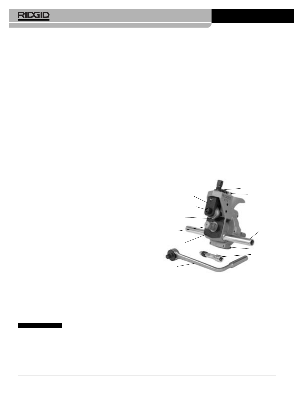
Rainureuse à galets mixte modèle 975
de la stabilité de l’ensemble du système de rainurage et des tuyaux à rainurer. Cela limitera les
risques de renversement du matériel et du tuyau.
Sécurité de la rainureuse à galets sur
chantier
• Sur chantier, la rainureuse doit être utilisée man-
uellement. Ne tentez pas d’utiliser de perceuses,
clés chocs, etc. pour la mouvoir. Ce type d’appareil
risquerait d’endommager les rainures et augmenter les
risques d’accident.
• Lors des travaux en élévation, l’ensemble du per-
sonnel environnant doit porter le casque et s’éloigner de la zone de chute potentielle de l’appareil.
Cela évitera de graves blessures corporelles en cas de
chute de la rainureuse, des tuyaux ou autres éléments environnants.
Description, caractéristiques
techniques et équipements de
base
Description
La rainureuse à galets mixte RIDGID 975, prévue pour
le rainurage des tuyaux acier, aluminium et PVC, permet
notamment le rainurage de tuyaux acier Série 10 et 40
de 11/4" à 6" de diamètre, ainsi que celui des tuyaux en
acier inoxydable Série 10 de 11/4" à 6" et Série 40 de 11/4"
à 2" de diamètre. Les rainures sont formées par la pression mécanique d’un galet de rainurage appliqué contre
un tuyau soutenu par un galet de roulement. La profondeur de rainure est le seul réglage nécessaire.
Cet appareil a été spécifiquement conçu pour une utilisation sur chantier ou sur système d’entraînement RIDGID
300 à 38 ou 57 t/min. Équipé de l’adaptateur approprié (réf.
67662), l’appareil peut également utiliser une fileteuse
RIDGID 300 Compact. La rainureuse à galets mixte type
975 incorpore une jauge de profondeur de rainurage
brevetée qui permet d’améliorer le contrôle du rainurage en
cours d’opération.
La rainureuse à galets mixte type 975, appareil portatif
destiné aux interventions ponctuelles sur chantier, n’est
pas prévue pour les travaux grand volume ou les travaux
en atelier.
AVIS IMPORTANT
rainureuse à galets mixte modèle 975 assure un rainurage
sur tuyaux de 2" à 6" de diamètre conforme à la norme
AWWA C606-06. Cela dit, le concepteur et/ou installateur
du réseau reste responsable de la sélection des matériaux
et moyens de raccordement appropriés. Il convient donc,
avant toute installation, d’étudier soigneusement le réseau
concerné (composition chimique, température, etc.).
Utilisée de manière appropriée, la
Caractéristiques techniques
Capacité :......................Tuyaux acier Ø 11/4" à 6",
séries 10 et 40 Avec changement de galets : tuyaux cuivre
Ø 2" à 4" types K, L, M et DWV
Réglage de
diamètre de rainure ......Vis de réglage et jauge de
profondeur
Mécanisme....................Vis d’avancement avec clé à
cliquet de 1/2"
Systèmes
d’entraînement : ...........Système RIDGID 300 (en 38
et 57 t/min uniquement)
Fileteuse RIDGID 300
Compact (avec adaptateur)
Poids..............................27,6 livres
La rainureuse à galets mixte nº 975 est protégée par
plusieurs brevets américains et internationaux, notamment
les brevets nº 6,272,895 et nº 6,591,652.
Vis d’avancement
Vis de réglage
Bloc coulissant
Axe de galet de
rainurage
Galet de
rainurage
Arbre
d’entraînement
Platine
Clé à cliquet
Figure 1 – Rainureuse à galets mixte nº 975
Jauge de
profondeur de
rainure
Support tubulaire
Embase
Rallonge
Équipements de base
Galets de rainurage et d’entraînement pour séries 10 et
40 de 11/4" à 6"
Clé à cliquet avec bouton de verrouillage (carré de 1/2")
Rallonge d’entraînement à verrouillage
Supports tubulaires
Jauge de profondeur graduée incorporée
Ridge Tool Company28
Page 31

Rainureuse à galets mixte modèle 975
Inspection de la rainureuse à
galets
AVERTISSEMENT
Examinez la rainureuse à galets avant chaque utilisation afin de corriger les problèmes éventuels et
réduire les risques d’écrasement ou autres
blessures, voire la détérioration de l’appareil.
Ne pas utiliser cette rainureuse à galets avec un
système d’entraînement dépourvu de sa pédale de
commande.
1. Si la rainureuse est montée sur système d’entraînement ou fileteuse, assurez-vous que ce dernier est
débranché et que son interrupteur FOR/OFF/REV
(marche avant/arrêt/marche arrière) se trouve en
position OFF (arrêt). Inspectez et entretenez le système d’entraînement/fileteuse selon les consignes
du mode d’emploi correspondant. Toute négligence au
niveau de l’inspection ou de l’entretien du système
d’entraînement augmenterait les risques de graves
blessures corporelles et de dégâts matériels. Vérifiez
la présence et le bon fonctionnement de la pédale de
commande du système d’entraînement. Ne montez
pas la rainureuse à galets sur un système d’entraînement dépourvu de sa pédale de commande.
2. Éliminez toutes traces d’huile, de graisse et de crasse
apparentes sur la rainureuse à galets, sa poignée de
transport et la clé à cliquet servant à l’activation de la
rainureuse. Cela évitera à l’appareil ou à la clé de
s’échapper de vos mains en cours d’utilisation et
limitera les risques de blessures consécutives.
blèmes de dérapage longitudinal et transversal en
cours de rainurage.
7. Examinez le galet de rainurage et l’arbre d’entraînement pour signes de fissuration, d’usure ou autre
détérioration. Des galets de rainurage et arbres
d’entraînement endommagés risquent de produire
un rainurage de mauvaise qualité ou provoquer la
défaillance de l’appareil en cours d’utilisation.
8. Assurez-vous du bon fonctionnement de la clé à cliquet et de sa rallonge. Vérifiez que la clé fonctionne
sans accrocs dans les deux sans. Appuyez sur le
bouton de déverrouillage au centre de la clé, puis
engagez-la sur le carré de la vis d’avancement. La clé
doit alors se verrouiller en position. La clé doit aussi
s’engager et se verrouiller sur sa rallonge, de même
que cette dernière sur le carré du système d’entraînement manuel qui se trouve au dos de la rainureuse.
Ce dispositif empêche le déboîtement accidentel de
la clé et de sa rallonge en cours d’utilisation. Si vous
utilisez une clé simple ou une clé à cliquet et rallonge
sans dispositif de verrouillage, sachez que celles-ci
risquent de se déboîter en cours d’utilisation.
En présence d’une anomalie quelconque, n’utilisez
pas l’appareil avant sa rectification.
9. Lubrifiez la rainureuse à galets selon les consignes
d’entretien du mode d’emploi, puis essuyez le galet de
rainurage pour éliminer toutes traces de graisse
résiduelle.
10. Examinez et entretenez l’ensemble du matériel accessoire éventuellement utilisé afin de vous assurer de
son bon fonctionnement.
3. Assurez-vous que les supports tubulaires de la rainureuse sont vissés à fond.
4. Examinez la rainureuse pour signes d’éléments
brisés, manquants, mal installés ou grippés qui pourraient nuire au bon fonctionnement et à la sécurité de
l’appareil. Vérifiez la libre rotation du galet de rainurage et de l’arbre d’entraînement.
5. Assurez-vous de la présence et de la bonne fixation
de l’étiquette de sécurité. Reportez-vous
2
pour l’emplacement de l’étiquette de sécurité.
à la Figure
6. Lorsque les bossages de l’arbre d’entraînement s’encrassent, nettoyez-les avec une brosse métallique.
Des bossages encrassés peuvent entraîner des pro-
Ridge Tool Company 29
Étiquette de
sécurité
Figure 2 – Étiquette de sécurité de la rainureuse à galets
mixte nº 975
Graisseurs
Page 32

Rainureuse à galets mixte modèle 975
Préparation de l’appareil et des
lieux pour l’utilisation d’un
système d’entraînement
AVERTISSEMENT
Portez systématiquement une protection oculaire
pour protéger vos yeux contre la projection de
débris. Portez des chaussures à coquille d’acier
pour protéger vos pieds en cas de renversement
de l’appareil ou des tuyaux.
Ne pas utiliser cette rainureuse à galets avec un
système d’entraînement ou fileteuse dépourvus de
pédale de commande. Ne jamais bloquer la pédale
de commande afin de l’empêcher de contrôler le
système d’entraînement. La pédale de commande
est un dispositif de sécurité qui vous permet
d’arrêter le système d’entraînement en lâchant le
pied. Si des vêtements se prennent dans l’appareil
pendant que le système d’entraînement continu à
tourner, ils seront entraînés dans l’appareil. Cet
appareil dispose d’un couple suffisamment élever
pour entortiller les vêtements autour d’un bras ou
autre membre avec suffisamment de force pour
écraser ou briser les os, voire provoquer d’autres
blessures.
Préparez la rainureuse et les lieux selon les consignes suivantes afin de limiter les risques de
blessure par choc électrique, incendie, renversement de l’appareil, entortillement, écrasement ou
autres causes, et afin d’éviter d’endommager la
rainureuse à galets.
1. Assurez-vous que les lieux présentent les caractéristiques suivantes :
• Suffisamment d’éclairage.
• L’absence de liquides, émanations ou poussières
potentiellement inflammables. Le cas échéant, ne
travaillez pas dans le secteur avant d’avoir identifié
et éliminé leur source. Les systèmes d’entraînement
et fileteuses ne sont pas blindés et risquent de
produire des étincelles.
• Un emplacement débarrassé, de niveau et au sec
pour l’utilisateur et l’ensemble du matériel. Ne pas
utiliser ce matériel lorsque vous avez les pieds
dans l’eau.
• Une prise de courant avec terre appropriée. Toute
prise avec terre ou disjoncteur différentiel n’est
pas nécessairement correctement reliée à la terre.
En cas de doute, faire vérifier l’installation par un
électricien.
• Un passage dégagé jusqu’à la prise de courant
qui ne contient rien qui puisse endommager le cordon d’alimentation.
2. Nettoyez les lieux avant d’installer le matériel. Essuyez
toutes traces d’huile au sol.
3. Examinez le tuyau à rainurer afin de confirmer que la
rainureuse à galet mixte nº 975 convient aux travaux
envisagés. La rainureuse à galets mixte nº 975 est
prévue pour le rainurage des tuyaux Ø 11/4" à 6" en
acier séries 10 et 40, aluminium ou PVC. Elle permet
également le rainurage des tuyaux en acier inoxydable série 10 en Ø 11/4" à 6", et de série 40 en Ø 11/4"
à 2" et, avec un changement de galets, celui des
tuyaux cuivre Ø 2" à 8" types K, L, M et DWV.
La rainureuse à galets mixte nº 975 peut servir in situ
(sur tuyaux déjà posés ou tenus dans un étau) ou sur
chantier avec un système d’entraînement type RIDGID
300, voire une rainureuse type 300 Compact, pour les
applications motorisées. La rainureuse à galets mixte
nº 975 n’est pas prévue pour les travaux industriels.
Des rainureuses à galets prévues pour d’autres types
d’application se trouvent dans le catalogue Ridge
Tool, en ligne au www.RIDGID.com ou auprès des
services techniques de la Ridge Tool Company en
composant le 800-519-3456.
AVIS IMPORTANT
L’utilisation d’un même jeu de galets
(rainurage et arbre d’entraînement) à la fois sur des tuyaux
en acier au carbone et en acier inoxydable risque de contaminer l’acier inoxydable. Une telle contamination pourrait
entraîner la corrosion et la défaillance prématurée des
tuyaux. Afin d’éviter les risques de contamination ferreuse
des tuyaux en acier inoxydable, utilisez des jeux de galets
spécifiquement réservés au rainurage des tuyaux inox. A
défaut, une brosse en acier inoxydable peut servir à
soigneusement nettoyer les galets entre le rainurage de
ces deux matériaux.
4. Effectuez l’inspection préalable du système d’entraînement ou de la fileteuse selon les consignes du manuel
correspondant. Vérifiez la présence de sa pédale
de commande et assurez-vous que son interrupteur
FOR/OFF/REV se trouve en position « OFF ». Préparez le système d’entraînement ou la fileteuse selon
les consignes du manuel correspondant. Assurezvous de la stabilité de l’appareil et de son trépied.
5. Ouvrez le mandrin du système d’entraînement (ou
fileteuse) complètement.
6. Une fois l’inspection préalable de la rainureuse à
galets mixte nº 975 terminée, vérifiez qu’elle est
équipée des galets de rainurage appropriés.
Ridge Tool Company30
Page 33

Montage de la rainureuse à galets mixte
o
975 sur système d’entraînement
n
RIDGID 300
1. Lorsque le système d’entraînement utilisé est déjà
équipé d’un chariot ou autres accessoires, déposezles. Vérifiez que les supports tubulaires du système
d’entraînement sont complètement déployés et verrouillés.
2. Positionnez les supports tubulaires de la rainureuse
sur les supports tubulaires du système d’entraînement
et, à l’extrémité de l’arbre d’entraînement de la rainureuse, dans le mandrin de l’appareil. Serrez le mandrin du système d’entraînement sur les plats de
l’arbre en vérifiant le centrage de l’arbre dans le
mandrin. Tournez le volant de serrage du mandrin
rapide sèchement à gauche à plusieurs reprises
pour assurer la retenue de l’arbre d’entraînement
(Figure 3)
.
Rainureuse à galets mixte modèle 975
Figure 4 – Montage de l’adaptateur d’arbre d’entraînement
2. Amenez le chariot de la fileteuse 300 Compact aussi
près que possible du mandrin de l’appareil. Relevez
le coupe-tubes, l’alésoir et la tête de filière de l’appareil
pour les dégager. Positionnez le cône de l’alésoir
dans la tête de filière.
Figure 3 – Montage de la rainureuse à galets mixte nº 975
sur mandrin de système d’entraînement nº 300.
Montage de la rainureuse mixte no975
sur fileteuse RIDGID Compact
L’entraînement de la rainureuse par fileteuse 300 Compact
nécessite l’utilisation d’un adaptateur spécial (réf. 67662).
Cet adaptateur assure l’alignement de la 975 vis-à-vis de
la fileteuse et son trépied, permettant ainsi le rainurage de
gamme entière des tuyaux prévus. Afin d’éviter les risques
de renversement ou autres accidents, ne jamais tenter
d’utiliser la rainureuse 975 avec d’autres types de fileteuse.
1. Montez l’adaptateur sur l’arbre d’entraînement de la
rainureuse
blocage sur les plats de l’arbre de la rainureuse.
(Figure 4)
en serrant à fond ses vis de
3. Positionnez l’adaptateur sur les rails de la 300
Compact, puis verrouillez-le en place à l’aide de la
broche attachée.
Figure 5 – Montage de l’adaptateur
4. Posez les tubulures de la 975 sur celles de l’adaptateur en positionnant la rallonge de l’arbre d’entraînement dans le mandrin de l’appareil. Fermez et serrez
le mandrin de l’appareil sur la rallonge de l’arbre
d’entraînement. Assurez-vous que l’arbre d’entraînement est bien centré dans le mandrin. Tournez le
volant du mandrin rapide sèchement à gauche à
plusieurs reprises pour assurer que l’arbre d’entraînement est bien tenu.
Ridge Tool Company 31
Page 34
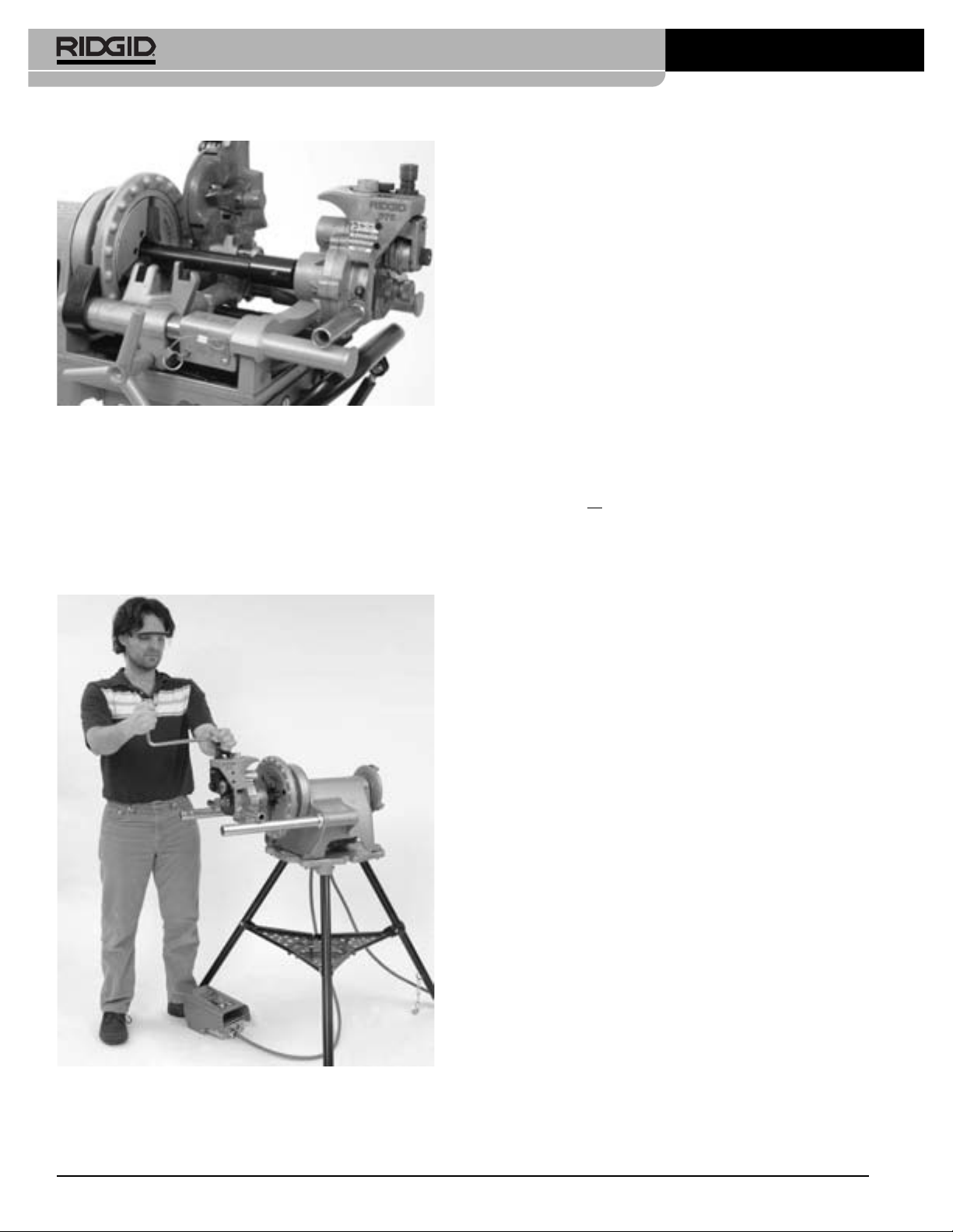
Rainureuse à galets mixte modèle 975
Figure 6 – Rainureuse à galets mixte nº 975 montée sur
fileteuse 300 Compact
Derniers préparatifs
1. Positionnez la pédale de commande de manière à
pouvoir simultanément contrôler le système d’entraînement ou fileteuse, la rainureuse et le tuyau à
rainurer. Comme indiqué à la
doit permettre à l’utilisateur de :
Figure 7,
cette position
• Pourvoir contrôler la fonction marche/arrêt de la
pédale de commande et pouvoir rapidement en
retirer son pied en cas de besoin.
• Pouvoir accéder facilement à la fois à la rainureuse,
au tuyau et à la clé à cliquet sans avoir à se pencher sur la rainureuse.
2. Passez le cordon d’alimentation le long du passage
dégagé décrit précédemment. Avec les mains sèches, branchez le système d’entraînement sur la prise
avec terre appropriée. Maintenez toutes connexions
électriques au sec et surélevées. Si le cordon d’alimentation n’est pas suffisamment long, prévoyez
une rallonge électrique :
• En bon état
• Disposant d’une fiche à trois barrettes semblable à
celle du système d’entraînement
• Homologuée pour utilisation à l’extérieur et com-
portant l’inscription W ou W-A dans sa désignation
(ex., SOW
) indiquant son homologation pour usage
à l’extérieur
• D’une section suffisante (14 AWG jusqu’à 25 pieds
de longueur, et 12 AWG de 25 à 50 pieds). Une rallonge ayant des fils conducteurs de section insuffisante risque de surchauffer, faire fondre sa gaine
isolante, et provoquer un incendie ou autres dégâts.
Figure 7 – Position de travail
• Se tenir face à la rainureuse du côte de son interrupteur FOR/OFF/REV.
3. Vérifiez le bon fonctionnement du système d’entraînement de la manière suivante :
• Mettez l’interrupteur du système d’entraînement
en position FOR (marche avant). Appuyez momentanément sur la pédale de commande en faisant
face à l’appareil pour vérifier que l’arbre d’entraînement tourne bien à gauche. Si le système d’entraînement tourne en sens inverse ou que la pédale
de commande ne contrôle pas son fonctionnement,
n’utilisez pas l’appareil avant sa réparation.
• Appuyez sur la pédale de commande le temps de
vérifier le régime de rotation de l’appareil et examiner le mécanisme pour signes de désalignement,
grippage bruits anormaux ou autres anomalies
potentielles. Lâchez la pédale de commande. Si le
régime de rotation du système d’entraînement est
supérieur à 57 t/min, ne l’utilisez pas pour le rainurage. Un régime de rotation trop élevé augmenterait les risques d’accident. En cas d’anomalie
quelconque, n’utilisez pas ce matériel avant sa
réparation.
• Mettez l’interrupteur du système d’entraînement
en position REV (marche arrière). Appuyez momentanément sur la pédale de commande en faisant
face à l’appareil pour vérifier que l’arbre d’entraînement tourne bien à droite. Si le système d’entraînement tourne en sens inverse, n’utilisez pas l’appareil
avant sa réparation.
Ridge Tool Company32
Page 35

Rainureuse à galets mixte modèle 975
• Ramenez l’interrupteur du système d’entraînement
à la position OFF (arrêt) puis, avec les mains sèches, débranchez l’appareil.
Préparation des tuyaux
AVIS IMPORTANT
verselles. Reportez-vous aux instructions du fabricant du
système de raccordement utilisé pour les consignes de
préparation spécifiquement applicables à son produit. Le
non-respect des consignes du fabricant du système de
raccordement risque de nuire à la qualité et à l’étanchéité
des raccords.
1. Coupez le tuyau à longueur. Respectez les indications
du Tableau A visant les longueurs minimales pour
chaque section de tuyau utilisé. Le rainurage de
tuyaux de longueur insuffisante augmenterait les
risques d’écrasement des doigts et d’enchevêtrement.
Assurez-vous d’une coupe bien d’équerre et de
l’absence de bavures. Lors du rainurage, des bavures
éventuelles risqueraient d’accrocher ou de couper
vos gants et vos doigts. La méthode de coupe utilisée
et la présence de bavures peuvent influencer la qualité et l’alignement des rainures. Ne jamais tenter de
rainurer un tuyau qui a été coupé au chalumeau.
2. Toutes soudures, bavures et coutures externes ou
internes doivent être meulées à fleur de tuyau sur un
minimum de 2" à partir de l’extrémité du tuyau. Ne
créez pas de plats dans la zone d’assise du joint
afin d’éviter les problèmes d’étanchéité.
3. Éliminez toutes traces de calamine, crasse, rouille ou
autre contamination sur un minimum de 2" à partir de
l’extrémité du tuyau. La moindre contamination risque
de colmater les bossages d’entraînement pour nuire
à l’avancement et à l’alignement du tuyau en cours de
rainurage.
Les consignes suivantes sont uni-
Présentation des tuyaux
1. Vérifiez que l’interrupteur du système d’entraînement
se trouve bien en position OFF.
Ø Longueur Longueur Ø Longueur Longueur
nominal mini maxi nominal mini maxi
1 8 36 4 8 36
4
11/
1
2
1
/
2 8 36 Ø 6 ext. 10 30
1
2
2
/
3 8 36
1
2
3
/
Tableau A – Longueurs de tuyau minimales et maximales
8 36 41/
8 36 5 8 32
8 36 6 10 28
8 36
pouvant être rainurées à l’aide d’un seul
porte-tubes (toutes dimensions en pouces)
2
8 32
3. Positionnez les porte-tubes nécessaires devant la
rainureuse. Lorsqu’un seul porte-tubes est utilisé,
positionnez-le à un peu plus de la moitié de la
longueur du tuyau (en partant de la platine de couverture de la rainureuse). Lors de l’utilisation de
plusieurs porte-tubes, ceux-ci devraient être placés au
quart de la longueur du tuyau depuis chaque extrémité de ce dernier. Dans certains cas, des portetubes supplémentaires risquent d’être nécessaires. La
hauteur des porte-tubes doit être réglée de manière
à permettre au tuyau de s’engager sur le galet
d’entraînement.
4. Assurez-vous que le galet de rainurage est suffisamment retiré pour permettre l’engagement du
tuyau sur l’arbre d’entraînement. Au besoin, dévissez
la vis d’avancement pour relever le galet de rainurage.
5. Après avoir enfilé le tuyau sur l’arbre d’entraînement, posez-le sur le ou les porte-tubes. Vérifiez la
stabilité du tuyau.
Platine de
couverture
2. Assurez-vous de pouvoir soutenir le tuyau de manière
appropriée. Le
Tableau A
indique les longueurs maximales de tuyau pouvant être rainurées à l’aide d’un
seul porte-tubes. Les tuyaux de longueur supérieure
devront être soutenus par un minimum de deux
porte-tubes. Un manque de soutien pourrait entraîner le renversement du tuyau et de l’appareil. Ne tentez pas de rainurer de tuyaux plus courts que les
longueurs minimales indiquées.
Ridge Tool Company 33
Figure 8 – Positionnement du tuyau sur l’arbre d’entraîne-
ment et contre la platine de couverture.
6. Ajustez le tuyau et les porte-tubes de manière à ce
que l’extrémité du tuyau s’appuie contre la platine de
couverture et que l’intérieur du tuyau repose sur l’arbre d’entraînement
(Figure 7)
. L’axe du tuyau doit être
aligné avec celui de l’arbre d’entraînement. Pour ce
faire, il s’agit de niveler à la fois le système d’entraînement/fileteuse et le tuyau.
Page 36

Rainureuse à galets mixte modèle 975
7. Déportez légèrement l’extrémité du tuyau et les portetubes vers l’utilisateur pour obtenir une dérivation
d’environ 0,5 degrés (voire, 25 mm à 3 mètres de la
rainureuse). Ce léger déport aidera à aligner le tuyau
en cours de rainurage
Axe du
tuyau
1
/2°
Figure 9 – Déport du tuyau de 0,5 degrés vers l’opéra-
teur (schématisé)
(Figure 9)
Axe de l’arbre
d’entraînement
.
8. Serrez la vis d’avancement pour amener le galet de
rainurage contre le tuyau, puis ajoutez-y un quart
de tour de plus. Il sera peut-être nécessaire de
desserrer la vis de réglage pour permettre au galet de
rainurage de contacter le tuyau. A ce stade, la rainureuse et le tuyau devraient être fermement engagés.
9. Examinez les lieux pour déterminer s’il est nécessaire
de les barricader afin d’éloigner autrui du matériel et
du tuyau. Des barrières ou barricades devraient être
prévues pour créer un périmètre de sécurité d’au
moins un mètre autour du système d’entraînement et
du tuyau. Ce périmètre de sécurité empêchera aux
passants de heurter accidentellement l’appareil et
le tuyau, évitant ainsi les risques de renversement et
d’entrave.
10. Avec les mains sèches, branchez le cordon d’alimentation de l’appareil sur une prise avec terre
appropriée.
Utilisation de la rainureuse à
galets mixte no975 sur système
d’entraînement ou fileteuse
AVERTISSEMENT
Ne portez pas de vêtements amples lors de l’utilisation de la rainureuse. Gardez vos manches et
blousons boutonnés. Ne vous penchez pas sur
l’appareil ou sur le tuyau. Les vêtements amples
risquent de s’entortiller dans le mécanisme et
provoquer des blessures par écrasement.
Éloignez vos mains des galets de rainurage. Ne
tentez pas de rainurer des tuyaux plus courts que
spécifiés. Ne portez pas de gants trop grands. Vos
doigts risquent d’être écrasés par les galets de
rainurage ou entre galet de rainurage et tuyau.
Éloignez vos mains de l’extrémité du tuyau. Ne
passez pas votre main à l’intérieur du tuyau. Les
bavures et rebords tranchants pourraient les
accrocher et les couper. Vos doigts risquent d’être
écrasés par les galets de rainurage ou entre galet
de rainurage et tuyau.
Portez systématiquement une protection oculaire
afin de protéger vos yeux contre les projections de
débris éventuelles. Portez des chaussures à coquille
d’acier pour protéger vos pieds en cas de renversement de l’appareil ou du tuyau.
Respectez les consignes du mode d’emploi afin de
limiter les risques de blessure par écrasement,
renversement, contusion ou autres causes.
Réglage et vérification du diamètre de
rainurage
AVIS IMPORTANT
caractéristiques physiques des tuyaux, un rainurage
d’essai s’impose avant le premier rainurage du jour, et lors
de chaque changement de section, série ou composition
de tuyau. Dans la mesure où la jauge de diamètre de rainure ne donne qu’une indication approximative du diamètre
réel, ce dernier doit être mesuré et confirmé.
1. Vérifiez l’installation du matériel et du tuyau. Une
mauvaise préparation de tuyau risquerait de nuire à
la précision initiale de la jauge de profondeur. Le
galet de rainurage doit alors toucher le tuyau.
2. Réglez la jauge de profondeur de rainurage de façon
à amener la graduation applicable sous la tête de la
vis de réglage
En raison des variations dans les
(Figure 10A)
. Cette jauge de pro-
Ridge Tool Company34
Page 37

Rainureuse à galets mixte modèle 975
fondeur est prévue pour les tuyaux acier.
Consultez
la section Contrôle de la profondeur de rainurage
sur tuyaux cuivre lors du rainurage du cuivre.
3. Serrez la vis de réglage jusqu’à ce que sa tête touche
la graduation de la jauge de profondeur. Tournez la
jauge de profondeur de rainurage à la position de rainurage
(Figure 10B)
. Si la jauge n’est pas en position
de rainurage, elle empêchera le rainurage et risque
d’être endommagée.
Figure 10A – Amenez la
graduation applicable de
la jauge sous de la tête de
la vis de réglage
Figure 10B – Jauge en
position de rainurage
4. Effectuez un échantillon de rainure selon les indications de la section
Façonnage des rainures
.
mètre de rainure se trouve au-delà des limites prescrites, il sera nécessaire de jouer sur la vis de
réglage pour obtenir le diamètre voulu.
• Pour augmenter le diamètre de la rainure, serrez
la vis de réglage.
• Pour réduire le diamètre de la rainure, desserrez
le vis de réglage.
• Chaque quart de tour de la vis de réglage modifie le
diamètre de rainurage par approximativement 0,02".
7. Répétez les étapes 4 à 6 jusqu’à ce que le diamètre
de la rainure se trouve dans les limites acceptables. Si
la rainure initiale est trop importante, la Rainure peut
être réglée afin de la réduire. Si la rainure est trop
petite, il sera nécessaire de façonner une autre rainure.
La précision diamétrale des rainures est indispensable
à l’étanchéité. Des rainures hors normes pourraient
entraîner la défaillance des joints d’étanchéité.
Façonnage des rainures
1. Vérifiez l’installation du matériel et du tuyau.
5. Mesurez le diamètre de la rainure. La mesure du
diamètre d’une rainure se fait le plus souvent à l’aide
d’un ruban de circonférence (voir la section «Accessoires»). Enveloppez le ruban bien à plat autour du
fond de la rainure pour mesurer le diamètre de la rainure
(Figure 11)
Figure 11 – Vérification du diamètre de rainure à l’aide
d’un ruban de circonférence
.
6. Comparez le diamètre de rainurage ainsi mesuré à
celui indiqué au
Tableau I ou à celui
précisé par le
fabricant du joint d’étanchéité en question. Si le dia-
Figure 12 – Positon de travail
2. Tenez-vous dans la position de travail indiquée.
Positionnez la pédale de commande du système
d’entraînement de manière à pouvoir contrôler simultanément le système d’entraînement, la rainureuse et
Ridge Tool Company 35
Page 38

Rainureuse à galets mixte modèle 975
le tuyau. Comme indiqué à la
Figure 12
, cette position
de travail doit permettre à l’utilisateur :
• De se positionner face à la rainureuse et accéder à
l’interrupteur FOR/OFF/REV.
• De commander la fonction marche/arrêt de la
pédale de commande, et, au besoin, de la lâcher
instantanément.
• D’accéder sans encombre à la rainureuse et à la
clé à cliquet sans avoir à se pencher sur l’appareil.
• De stabiliser le tuyau à l’aide de sa main droite si
nécessaire.
• De maintenir une bonne assise et un bon équilibre.
3. Mettez l’interrupteur FOR/OFF/REV en position REV
(marche arrière). N’utilisez pas la rainureuse à galets
mixte nº 975 en position FOR (marche avant). En
raison de la conception de la rainureuse nº 975,
cela aurait pour effet d’envoyer le tuyau en spirale
et risque de le faire tomber de la rainureuse.
4. Mettez une main sur la tête de la clé à cliquet ou la
molette de la vis d’avancement, tout en tenant sa
poignée de l’autre.
5. Appuyez sur la pédale de commande pour lancer le
système d’entraînement. Observez la rotation du
tuyau en vous assurant qu’il reste plaqué contre la platine de couverture de la rainureuse. Si le tuyau commence à s’éloigner de la platine, lâchez la pédale de
commande afin d’éviter que le tuyau parte en spirale et qu’il tombe de l’appareil. Au besoin, préparez le
tuyau à nouveau selon les indications de la section
Préparation des tuyaux
. Si l’extrémité du tuyau est
déformée, il sera nécessaire de la tronçonner à nouveau et de préparer une nouvelle rainure.
6. Après une rotation complète du tuyau, serrez la vis
d’avancement d’un quart de tour supplémentaire.
Continuez à observer l’extrémité du tuyau pour vous
assurer qu’elle reste plaquée contre la platine de
couverture. Ne serrez pas la vis d’avancement de
plus d’un quart de tour par rotation. Le serrage trop
agressif de la vis d’avancement risque de trop évaser la rainure ou faire partir le tuyau en spirale et le
déloger de l’arbre d’entraînement.
7. Continuez de serrez la vis d’avancement d’un quart
de tour par rotation jusqu’à ce que la tête de la vis
d’avancement bute contre le sommet de la rainureuse. Arrêtez de serrer la vis d’avancement dès
qu’elle atteint le sommet de la rainureuse afin d’éviter
d’endommager la vis de réglage. Laissez tourner le
tuyau sur deux rotations complètes supplémentaires
en cette position afin d’assurer l’uniformité de la profondeur de rainure.tations in this position to insure uniform groove depth.
8. Lâchez la pédale de commande et mettez l’interrupteur FOR/OFF/REV en position OFF.
9. Dévissez la vis d’avancement afin de ramener le
galet de rainurage suffisamment pour retirer le tuyau
de l’appareil.
10. Examinez la rainure.
• Assurez-vous que le rainurage est complet.
• Vérifiez le diamètre de la rainure afin de vous
assurer de sa conformité aux normes prévues.
• Vérifiez tout autre point de contrôle demandé par le
fabricant du joint.
En cas d’anomalie, cette rainure ne pourra pas être utilisée.
Réglage du diamètre de rainure pour
tuyaux en cuivre
La jauge de profondeur de rainure de la 975 ne peut
pas servir à la vérification de profondeur de rainure sur les
tuyaux en cuivre. Elle donnerait de fausses indications de
diamètre.
1. Vissez la vis d’avancement jusqu’à amener le galet de
rainurage contre le tuyau, puis ajoutez-y un quart
de tour supplémentaire. Il sera peut-être nécessaire
de desserrer la vis de réglage afin de permettre au
galet de rainurage de descendre jusqu’au tuyau. Le
tuyau et la rainureuse devrait alors être solidaires
l’un de l’autre.
2. Assurez-vous que la jauge de profondeur de rainure
se trouve en position de rainurage
3. Tournez la vis de réglage jusqu’à ce qu’elle arrive à
fleur de la platine supérieure de la rainureuse.
4. Consultez le Tableau B pour déterminer le nombre
de tours qu’il faudra ramener la vis de réglage en
fonction du diamètre et type du tuyau en question.
Pour un tuyau en cuivre série « L » de 4 pouces de
diamètre, par exemple, il sera nécessaire de ramener la vis de réglage de 11/4tours.
Réglage de profondeur pour le rainurage des
tuyaux en cuivre
(Tours de vis)
Dia. K L M DWV
2-2.5"
3" 11/
4" 11/
5" 11/
6" 113/
8" 21/
Tableau B – Réglage de profondeur pour le rainurage
Revenez à l’article 4 de la section « Réglage et
5.
7
8
/
16
4
2
16
2
11/
11/
11/
13/
23/
7
8
/
16
4
2
4
8
des tuyaux en cuivre
mesure des diamètres de rainure ».
(Figure 10B)
5
8
/
16
11/
11/
11/
13/
21/
4
2
4
8
11/
11/
11/
13/
21/
.
5
8
/
16
8
2
4
8
Ridge Tool Company36
Page 39

Rainureuse à galets mixte modèle 975
Conseils visant les problèmes d’alignement avec la rainureuse à galets mixte
o
975
n
Les problèmes les plus souvent rencontrés lors du rainurage d’un tuyau sont sa tendance à partir en spirale, à
«trotter» ou à se désaligner. Le maintien de l’alignement
du tuyau dépend du respect absolu de l’ensemble des
instructions données. Si, même en respectant ces instructions, le tuyau se désaligne toujours, il existe plusieurs
options pour y remédier.
• Augmentez légèrement de déport axial du tuyau de 1/
degré à 1 degré
• Appuyez légèrement sur le tuyau durant le rainurage
pour maintenir son alignement. Cela n’est généralement nécessaire que sur les petites longueurs de
tuyau. Pour ce faire, portez un gant en cuir intact afin
tenir le centre du tuyau comme indiqué à la
Il sera peut-être alors nécessaire d’arrimer le trépied
du système d’entraînement/fileteuse au sol afin
d’éviter qu’il bouge durant le rainurage. Afin d’éviter
les risques de blessure par écrasement, éloignez
vos mains du galet de rainurage et des extrémités du
tuyau, et ne tentez pas de rainurer de tuyaux plus
courts que recommandé.
(Figure 9)
.
Figure 13
• Consultez par ailleurs la section Dépannage pour
une liste complète des causes de désalignement et
les solutions correspondantes.
Préparation de l’appareil et du
chantier pour les interventions
in situ.
AVERTISSEMENT
2
.
Portez systématiquement une protection oculaire
pour protéger vos yeux contre la projection de
débris. Portez des chaussures à coquille d’acier
pour protéger vos pieds en cas de renversement de
l’appareil ou des tuyaux. Portez le casque lorsque
vous travaillez sur chantier.
Préparez la rainureuse et le chantier selon les consignes suivantes afin de limiter les risques de
blessure par choc électrique, incendie, renversement de l’appareil, entortillement, écrasement ou
autres causes, et afin d’éviter d’endommager la
rainureuse à galets.
Figure 13 – Appuyer sur le tuyau pour maintenir son
alignement durant le rainurage.
1. Assurez-vous que les lieux présentent les carac-
téristiques suivantes :
• Suffisamment d’éclairage.
• L’absence de liquides, émanations ou poussières
potentiellement inflammables. Le cas échéant, ne travaillez pas dans le secteur avant d’avoir identifié et
éliminé leur source. Le système d’entraînement
RIDGID 300 Power Drive n’est pas blindé et risque
de produire des étincelles.
• Un emplacement débarrassé, de niveau et au sec
pour l’utilisateur et l’ensemble du matériel. Ne pas
utiliser ce matériel lorsque vous avez les pieds
dans l’eau.
2. Nettoyez les lieux avant d’installer le matériel. Essuyez
toutes traces d’huile au sol.
3. Examinez le tuyau à rainurer afin de confirmer que
la rainureuse à galet mixte nº 975 convient aux
travaux envisagés. La rainureuse à galets mixte nº
975 est prévue pour le rainurage des tuyaux Ø 11/4"
à 6" en acier séries 10 et 40, aluminium ou PVC.
Elle permet également le rainurage des tuyaux en
acier inoxydable de la série 10 en Ø 11/4" à 6", et de
la série 40 en Ø 11/4" à 2".
La rainureuse à galets mixte nº 975 peut servir sur
chantier (sur tuyaux déjà posés ou tenus dans un
Ridge Tool Company 37
Page 40

Rainureuse à galets mixte modèle 975
étau) ou avec un système d’entraînement type
RIDGID 300 ou fileteuse 300 Compact pour les applications motorisées. La rainureuse à galets mixte nº
975 n’est pas prévue pour les travaux industriels.
4. Lors des rainurages in situ, assurez-vous qu’il y aura
suffisamment de place pour permettre à la rainureuse
à galets mixte nº 975 d’évoluer. Pour que la rainureuse puisse tourner autour d’un tuyau solidement
soutenu, il lui faut :
• Un minimum de 6,5 pouces d’espace libre autour
du tuyau à rainurer.
• Une saillie de tuyau d’au moins 2,5 pouces par
rapport aux obstacles éventuels (murs, etc.).
• Un recul d’au moins 9, 5 pouces pour permettre le
montage de la rainureuse sur le tuyau.
Des rainureuses à galets prévues pour d’autres types
d’application se trouvent dans le catalogue Ridge
Tool, en ligne au www.RIDGID.com ou auprès des
services techniques de la Ridge Tool Company en
composant le 800-519-3456.
AVIS IMPORTANT
lets (rainurage et arbre d’entraînement) à la fois sur des
tuyaux en acier au carbone et en acier inoxydable risque
de contaminer l’acier inoxydable. Une telle contamination
pourrait entraîner la corrosion et la défaillance prématurée
des tuyaux. Afin d’éviter les risques de contamination
ferreuse des tuyaux en acier iznoxydable, utilisez des
jeux de galets spécifiquement réservés au rainurage des
tuyaux inox. A défaut, une brosse en acier inoxydable peut
servir à soigneusement nettoyer les galets entre le rainurage de ces deux matériaux.
L’utilisation d’un même jeu de ga-
Préparation des tuyaux
AVIS IMPORTANT
isées. Reportez-vous systématiquement aux instructions
du fabricant du système de raccordement utilisé pour
les consignes de préparation de tuyau applicables. Le
non-respect des consignes du fabricant du système de
raccordement risque de nuire à la qualité et à l’étanchéité
des raccords produits.
1. Lors du rainurage d’un tuyau sur canalisation existante, assurez-vous que le réseau est vide et dépressurisé. Renseignez-vous sur son contenu et sur les
risques éventuels que celui-ci représente.
2. Coupez le tuyau à longueur.
Assurez-vous d’une coupe bien d’équerre et de
l’absence de bavures. Lors du rainurage, des bavures
éventuelles risqueraient d’accrocher ou de couper
vos gants et vos doigts. La méthode de coupe utilisée
et la présence de bavures peuvent influencer la qualité et l’alignement des rainures. Ne jamais tenter de
rainurer un tuyau qui a été coupé au chalumeau.
Il s’agit ici de consignes général-
3. Toutes soudures, bavures et coutures internes ou
externes éventuelles doivent être meulées à fleur
de tuyau sur un minimum de 2" à partir de l’extrémité
du tuyau. Ne créez pas de plats dans la zone d’assise
du joint afin d’éviter les problèmes d’étanchéité.
4. Éliminez toutes traces de calamine, crasse, rouille ou
autre contamination sur un minimum de 2" à partir de
l’extrémité du tuyau. La moindre contamination risque
de colmater les bossages d’entraînement pour nuire
à l’avancement et à l’alignement du tuyau en cours de
rainurage.
5. Assurez-vous que le tuyau à rainurer est solidement
monté. Le tuyau doit pouvoir supporter, sans bouger,
le poids de la rainureuse (28 livres), ainsi que l’effort
et le couple produits par le rainurage. Dans certains
cas, il sera peut-être préférable de retirer le tuyau et
le rainurer sur un étau. Dans d’autres cas, il sera
peut-être nécessaire de renforcer ses supports de
manière temporaire ou permanente. Lors de l’utilisation d’un étau à tuyaux, assurez-vous qu’il est bien
arrimé et qu’il ne risque pas de se renverser en cours
de rainurage. Pour les tuyaux de grande longueur,
prévoyez les porte-tubes appropriés pour les soutenir.
Montage de la rainureuse sur le tuyau
1. Vérifiez que la rainureuse à galets mixte nº 975 a bien
été inspectée. Assurez-vous que les supports tubulaires sont bien vissés à fond dans le bâti de la rainureuse ou, le cas échéant, enlevez-les pour mieux
accéder aux endroits exigus. Ensuite, installez la clé
à cliquet sur la vis d’avancement, puis la rallonge
dans le carré d’entraînement manuel qui se trouve au
dos de la rainureuse. Assurez-vous que la clé et la rallonge sont bien engagées.
2. Assurez-vous qu’il y a suffisamment d’espace entre le
galet de rainurage et l’arbre d’entraînement pour
accommoder l’épaisseur du tuyau. Au besoin, dévissez la vis d’avancement pour ramener le galet de rainurage.
3. Tenez la rainureuse fermement entre vos mains. Ne
tentez pas de la soulever par la clé à cliquet. Positionnez l’arbre d’entraînement dans le tuyau en
vous assurant que la platine de couverture vient bien
à buter contre l’extrémité du tuyau
la vis d’avancement manuellement jusqu’à ce que le
galet de rainurage vienne s’appuyer contre le tuyau,
puis ajoutez-y un quart de tour à l’aide de la clé à cliquet. Assurez-vous que la rainureuse est fermement
accroché et que sa platine de couverture est plaquée
contre l’extrémité du tuyau. Sinon, répétez le processus. Lors des travaux in situ, vérifiez systéma-
(Figure 14)
. Serrez
Ridge Tool Company38
Page 41

Rainureuse à galets mixte modèle 975
tiquement la bonne tenue de la rainureuse afin de
l’empêcher de tomber.
Platine de
couverture
Figure 14 – Tenez la rainureuse fermement en position
lors du serrage de la vis d’avancement.
Utilisation in situ de la
rainureuse à galets mixte no975
AVERTISSEMENT
Eloignez vos mains de l’extrémité du tuyau. Ne
passez pas votre main à l’intérieur du tuyau. Les
bavures et rebords tranchants pourraient les
accrocher et les couper. Vos doigts risquent d’être
écrasés par les galets de rainurage ou entre galet
de rainurage et tuyau.
Portez systématiquement une protection oculaire
afin de protéger vos yeux contre les projections de
débris éventuelles. Portez des chaussures à coquille
d’acier pour protéger vos pieds en cas de renversement de l’appareil ou du tuyau.
Respectez les consignes du mode d’emploi afin de
limiter les risques de blessure par écrasement,
renversement, contusion ou autres causes.
Réglage et vérification du diamètre de
rainurage
AVIS IMPORTANT
caractéristiques physiques des tuyaux, un rainurage
d’essai s’impose avant le premier rainurage du jour, et lors
de chaque changement de section, série ou composition
de tuyau. Dans la mesure où la jauge de diamètre de
rainure ne donne qu’une indication approximative du
diamètre réel, ce dernier doit être mesuré et confirmé.
1. Vérifiez l’installation du matériel et du tuyau. Une
mauvaise préparation de tuyau risquerait de nuire à
la précision initiale de la jauge de profondeur. Le
galet de rainurage doit alors toucher le tuyau.
2. Réglez la jauge de profondeur de rainurage de façon
à amener la graduation applicable sous la tête de la vis
de réglage
prévue pour les tuyaux en acier. Reportez-vous à la
section
« Diamètre de rainurage pour tuyaux cuivre »
lors du rainurage des tuyaux en cuivre.
En raison des variations dans les
(Figure 15A)
. La jauge de profondeur est
N’utilisez que le système d’entraînement manuel
lors des rainurages à pied d’?uvre. Ne jamais utiliser de système d’entraînement mécanique (perceuse
électrique, clés choc, etc.) pour la mouvoir in situ.
L’utilisation de moyens mécaniques risquerait
d’endommager la rainureuse et augmenterait les
risques d’accident.
Ne portez pas de vêtements amples lors de l’utilisation de la rainureuse. Gardez vos manches et
blousons boutonnés. Ne vous penchez pas sur
l’appareil ou sur le tuyau. Les vêtements amples
risquent de s’entortiller dans le mécanisme et
provoquer des blessures par écrasement.
Éloignez vos mains des galets de rainurage. Ne
tentez pas de rainurer des tuyaux plus courts que
spécifiés. Ne portez pas de gants trop grands. Vos
doigts risquent d’être écrasés par les galets de
rainurage ou entre galet de rainurage et tuyau.
Ridge Tool Company 39
3. Serrez la vis de réglage jusqu’à ce que sa tête touche
la graduation de la jauge de profondeur. Tournez la
jauge de profondeur de rainurage à la position de rainurage
(Figure 15B)
. Si la jauge n’est pas en position
de rainurage, elle empêchera le rainurage et risque
d’être endommagée.
Figure 15A – Amenez la
graduation applicable de
la jauge sous de la tête de
la vis de réglage
Figure 15B – Jauge en
position de rainurage
Page 42

Rainureuse à galets mixte modèle 975
4. Effectuez un échantillon de rainure selon le processus
décrit à la section
Façonnage des rainures.
5. Mesurez le diamètre de la rainure. La mesure du
diamètre d’une rainure se fait le plus souvent à l’aide
d’un ruban à circonférence
soires»)
. Enveloppez le ruban bien à plat autour du
(voir la section «Acces-
fond de la rainure pour mesurer le diamètre de la rainure
(Figure 16)
Figure 16 – Vérification du diamètre de rainure à l’aide
d’un ruban à circonférence
.
Façonnage des rainures
1. Vérifiez l’installation appropriée du matériel et du
tuyau.
2. Mettez-vous en position de travail en répartissant
bien votre poids et en maintenant un bon équilibre.
3. Vérifiez que la vis d’avancement a bien été serrée
d’un quart de tour.
4. Enlevez la clé à cliquet de la vis d’avancement et
installez-y la rallonge. A noter que l’on peut se dispenser de la rallonge dans les endroits étriqués.
5. Tournez la clé à droite (vu de l’arrière de la rainureuse), dans le sens des flèches estampées au
dos de la rainureuse
de la rainureuse en vérifiant que sa platine de couverture reste bien plaquée contre l’embout du tuyau.
Si la rainureuse commence à s’éloigner du tuyau,
arrêtez de tourner la clé à cliquet afin d’éviter que la
rainureuse parte en spirale et tombe du tuyau.
Appuyez sur le support tubulaire de la rainureuse
pour aider à ramener sa platine de couverture contre
l’embout du tuyau. Au besoin, réinstallez la rainureuse sur le tuyau selon les indications de la section
Montage de la rainureuse sur le tuyau.
tuyau a été déformé, il sera nécessaire de le tronçonner à nouveau et de préparer une nouvelle rainure.
(Figure 17)
. Observez la rotation
Si l’embout du
6. Comparez le diamètre de rainurage ainsi mesuré à
celui indiqué au
Tableau I ou à celui
précisé par le
fabricant du joint d’étanchéité en question. Si le
diamètre de rainure se trouve au-delà des limites
prescrites, il sera nécessaire de jouer sur la vis de
réglage pour obtenir le diamètre voulu.
• Pour augmenter le diamètre de la rainure, serrez la
vis de réglage.
• Pour réduire le diamètre de la rainure, desserrez le
vis de réglage.
• Chaque quart de tour de la vis de réglage modifie le
diamètre de rainurage par approximativement 0,02".
7. Répétez les étapes 4 à 6 jusqu’à ce que le diamètre
de la rainure se trouve dans les limites acceptables.
Si la rainure initiale est trop importante, la Rainure
peut être réglée afin de la réduire. Si la rainure est
trop petite, il sera nécessaire de façonner une autre
rainure. La précision diamétrale des rainures est
indispensable à l’étanchéité. Des rainures hors
normes pourraient entraîner la défaillance des joints
d’étanchéité.
Tournez
Figure 17 – Tournez la clé dans le sens des flèches
6. Continuez de tourner la clé jusqu’à ce que la rainureuse ait achevée au moins une rotation complète
autour du tuyau. Enlevez la clé de l’extension, puis
engagez la sur la vis d’avancement. Ne serrez pas la
vis d’avancement de plus d’un quart de tour par
révolution de la rainureuse. Le serrage agressif de la
vis d’avancement risquerait d’évaser la rainure de
manière excessive et faire trotter la rainureuse jusqu’à
ce qu’elle tombe du tuyau. Continuez d’actionner la
clé pour faire tourner la rainureuse autour du tuyau,
Ridge Tool Company40
Page 43

Rainureuse à galets mixte modèle 975
tout en contrôlant la position de la platine de couverture par rapport à l’extrémité du tuyau.
7. Continuez de serrer la vis d’avancement d’un quart de
tour par révolution de la rainureuse autour du tuyau
jusqu’à ce que la tête de la vis de réglage bute contre
le sommet de la rainureuse. Arrêtez de serrer la vis
d’avancement dès qu’elle atteint le sommet de la
rainureuse afin d’éviter d’endommager la vis de
réglage. Laissez tourner le tuyau sur deux révolutions
complètes supplémentaires en cette position afin
d’assurer l’uniformité de la profondeur de rainure.
8. Ramenez la clé à cliquet sur la vis d’avancement.
Tenez fermement la rainureuse, puis tournez la vis
d’avancement à gauche pour éloigner le galet de
rainurage du tuyau. Ne laissez pas tomber la rainureuse.
9. Examinez la rainure.
• Assurez-vous que le rainurage est complet.
• Vérifiez le diamètre de la rainure afin de vous
assurer qu’elle tombe dans les limites prévues.
• Vérifiez tout autre article demandé par le fabri-
cant du joint.
Nettoyage de l’appareil
Nettoyez les bossages de l’arbre d’entraînement au moins
quotidiennement, et plus souvent si nécessaire, à l’aide
d’une brosse métallique.
Remplacement des galets
AVERTISSEMENT
ou des éléments associés, vérifiez que les repères des
galets de rainurage et d’entraînement correspondent.
Des éléments dépareillés peuvent nuire à la qualité du
rainurage et à l’étanchéité du raccord.
Retirez la rainureuse du système d’entraînement ou de la
fileteuse et posez-la sur un établi stable.
Outillage nécessaire :
• Clé 6-pans de
• Clé 6-pans de 3/32"
• Pince à cerclip de 0,070"
Dépose et montage du galet d’entraînement
1. Retirez les 6 vis de retenue du carter.
2. Retirez le carter
Lors du remplacements des galets
3
/8"
(Figure 18)
.
En cas d’anomalie, n’utilisez pas la rainure.
Consignes d’entretien
AVERTISSEMENT
Assurez-vous que l’interrupteur du système
d’entraînement se trouve en position OFF et que
l’appareil a été débranché avant toute intervention
ou réglage.
Lubrification
Lubrifiez la rainureuse à galets mixte nº 975 mensuellement à l’aide d’une graisse universelle de qualité.
• Les graisseurs se trouvent du côté «opérateur»
de l’embase, devant le bloc coulissant, et en bout
de l’axe du galet de rainurage
les à refus (voire, jusqu’au premier signe de dégorgement de graisse).
• Appliquez une légère couche de graisse sur la vis
d’avancement.
• La boîte d’engrenages de la rainureuse à galets
mixte nº 975 est étanche et ne nécessitera pas
de graissage tant qu’elle n’aura pas été ouverte.
(Figure 2)
. Graissez-
Carter
Figure 18 – Retrait du carter
3. Retirez le pignon.
4. Retirez l’arbre d’entraînement via l’arrière de la rainureuse 975.
5. Enlevez le cerclip de l’arbre d’entraînement et retirez
la couronne dentée
(Figure 19).
Reportez-vous à la section Inspection de l’appareil pour
des renseignements complémentaires visant son entretien.
Ridge Tool Company 41
Page 44

Rainureuse à galets mixte modèle 975
Couronne
dentée
Cerclip
Butée
Figure 19 – Retrait du cerclip
6. Retirez la clavette, puis la butée.
7. Enfilez la butée sur le nouvel arbre d’entraînement.
8. Enfoncez la clavette, puis montez la couronne dentée.
9. Installez le cerclip dans la rainure de l’arbre d’entraînement.
10. Positionnez l’arbre d’entraînement assemblé dans
le bâti de la rainureuse.
11. Enduisez les paliers et les dents de la couronne
d’une copieuse couche de graisse universelle de
bonne qualité.
12. Introduisez le pignon et remontez le carter. Serrez les
vis du carter à un couple de 12 à 16 ft-lbs.
Bâti
Couronne
dentée
Vis
Carter
Pignon
Butée
d’entraînement
Clavette
Arbre
Cerclip
Figure 20 – Composants de la rainureuse à galets nº 975
Dépose et montage du galet de rainurage
1. Retirez la vis de retenue de l’axe du galet de rainurage.
2. Retirez l’axe du galet de rainurage de l’étrier, puis
enlevez le galet de rainurage et la butée.
3. Introduisez la nouvelle butée et le galet de rainurage
de remplacement dans l’étrier, tout en vérifiant que le
cerclip intérieur du galet de rainurage est face au
bâti de la rainureuse, et que le galet de rainurage se
trouve entre la butée et le bâti.
Bâti
Vis de
Étrier
retenue
Butée
Galet de
rainurage
Figure 21
4. Remontez l’axe du galet de rainurage et sa vis de
retenue.
5. Vérifiez l’alignement des galets de rainurage et
d’entraînement. S’ils ne s’alignent pas, vérifiez l’orientation du galet de rainurage et de la butée.
6. Graissez l’ensemble selon les indications de la section
Lubrification
.
Accessoires
AVERTISSEMENT
Les produits suivants sont les seuls à être compatibles avec la rainureuse à galet mixte n
Toute tentative d’utilisation d’accessoires compatibles avec d’autres types d’appareil risque de
compromettre la sécurité de fonctionnement de
la rainureuse à galets mixte n
o
975. Afin de limiter
les risques d’accident grave, n’utilisez que les
accessoires spécifiquement prévus pour fonctionner avec la rainureuse à galets mixte n
que ceux répertoriés ci-après.
Réf.
catalogue Description
41855 Système d’entraînement type 300 Power Drive,
115V, 25 à 60 Hz, 38 t/min
75075 Système d’entraînement type 300 Power Drive,
115V, 23 à 60 Hz, 57 t/min
42360 Support n
o
1206 pour système d’entraînement type 300
66947 300 Compact, 115V, 23 à 60 Hz, 38 t/min
73447 300 Compact, 115V, 23 à 60 Hz, 52 t/min
67662 Adaptateur pour 300 Compact
67657 Support pliant n
72037 Étau à chaîne portable n
o
250 pour 300 Compact
o
480 sur trépied
56662 Porte-tubes en V surélevé type VJ-99
76822 Ruban à circonférence (impérial)
76827 Ruban à circonférence (métrique)
30708 Rallonge à verrouillage, carré de
30703 Clé à cliquet avec carré de
1
/2"
1
/2" et poignée à 90°
32833 Galets de rainurage et d’entraînement pour tuyaux
cuivre type K, L, M et DWV de 2" à 8"
o
o
975, tels
975.
Ridge Tool Company42
Page 45

Stockage de l’appareil
AVERTISSEMENT
sous clé hors de la porté des enfants et autres individus
non familiarisés avec le fonctionnement des rainureuses
à galets. Cet appareil peut devenir dangereux entre les
mains d’utilisateurs novices.
Remisez l’appareil dans un local
Service après-vente
AVERTISSEMENT
Une intervention mal exécutée risque de rendre
ce type d’accessoire dangereux.
La rubrique « Entretien de l’appareil » devrait couvrir la
majorité des besoins d’entretien de cet appareil. Veuillez
adresser tout problème qui n’est pas couvert sous cette
rubrique à un réparateur RIDGID agréé.
Aucunes pièces de rechange ne sont disponibles pour
ces accessoires. En cas de besoin de pièces, Tout
accessoire ayant besoin de pièces de rechange devrait
être mis au rebut et remplacé par un élément neuf.
Veuillez adresser toutes questions éventuelles visant
l’entretien ou la réparation de ce matériel aux coordonnées suivantes :
Ridge Tool Company
Technical Service Department
400 Clark Street
Elyria, Ohio 44035-6001
Tél. (800) 519-3456
E-mail: TechServices@ridgid.com
Pour obtenir les coordonnées du réparateur autorisé le
plus proche, veuillez consulter la Ridge Tool Company au
(800) 519-3456 ou www.RIDGID.com.
Rainureuse à galets mixte modèle 975
Ridge Tool Company 43
Page 46

Rainureuse à galets mixte modèle 975
Tableau I – Spécifications pour rainures normalisées
NOTA ! Toutes dimensions en pouces (système impérial).
Ø Ø Ep. mini Fond de Largeur Diamètre Profondeur
TUYAU TUYAU des joint de rainure de rainure de rainure
(nominal) Ext. Int. parois +.015/-.030 +.030/-.015 Ext. Int. (nominale) (2)
1
4
1
/
1.660 +.016 .065 .625 .344 1.535 +.000 .063
-.016 -.015
1
2
1
/
1.900 +.016 .065 .625 .344 1.775 +.000 .063
-.016 -.015
(1)
2
2.375
+
.024 .065 .625 .344 2.250 +.000 .063
-.016 -.015
1
(1)
2
2
/
2.875
+
.029 .083 .625 .344 2.720 +.000 .078
-.016 -.015
(1)
3
3.50
+
.030 .083 .625 .344 3.344 +.000 .078
-.018 -.015
1
(1)
2
3
/
4.00
+
030 .083 .625 .344 3.834 +.000 .083
-.018 -.015
(1)
4
4.50
+
.035 .083 .625 .344 4.334 +.000 .083
-.020 -.015
(1)
5
5.563
+
.056 .109 .625 .344 5.395 +.000 .084
-.022 -.015
(1)
6
6.625
+
.050 .109 .625 .344 6.455 +.000 .085
-.024 -.015
(1)Selon la norme AWWA C606-87
(2)La profondeur nominale des rainures n’est donnée qu’à titre indicatif. Ne pas baser la conformité d’une rainure sur sa profondeur.
TA B C D
Tableau II – Épaisseur maxi/mini des parois de tuyau
NOTA ! Toutes dimensions en pouces (système impérial)
Tuyau ou tube acier au Tuyau ou tube acier
carbone ou aluminium inoxydable Tuyau PVC
Ø tuyau
1
1
/4" .065 .140 .065 .140 .140 .140
1
1
/2" .065 .145 .065 .145 .145 .200
2" .065 .154 .065 .154 .154 .154
1
2
/2" .083 .203 .083 .188 .203 .276
3" .083 .216 .083 .188 .216 .300
1
3
/2" .083 .226 .083 .188 .226 .300
4" .083 .237 .083 .188 .237 .300
5" .109 .258 .109 .188 .258 .300
6" .109 .280 .109 .188 .280 .300
Epaisseur des parois Epaisseur des parois Epaisseur des parois
Mini Maxi Mini
Maxi Mini Maxi
Ridge Tool Company44
Page 47

Rainureuse à galets mixte modèle 975
Tableau III – Spécifications de rainurage pour cuivre
1 2 345678
AB CDT
Ø Siège Largeur Ø Prof. Ép. Évasement
nominal Ø ext. joint rainure rainure rainure mini maxi
(pouces) A +.03 +.00 nom.
Norme Tolérance ±0.03 –.000 –.02 parois
2" 2.125 ±0.002 0.610 0.300 2.029 0.048 DWV 2.220
21/2" 2.625 ±0.002 0.610 0.300 2.525 0.050 0.065 2.720
3" 3.125 ±0.002 0.610 0.300 3.025 0.050 DWV 3.220
4" 4.125 ±0.002 0.610 0.300 4.019 0.053 DWV 4.220
5" 5.125 ±0.002 0.610 0.300 5.019 0.053 DWV 5.220
6" 6.125 ±0.002 0.610 0.300 5.999 0.063 DWV 6.220
8" 8.125 +0.002/-0.004 0.610 0.300 7.959 0.083 DWV 8.220
1. La profondeur nominale de rainurage n’est donnée qu’à titre indicatif. Ne pas utilise r cette profonde ur pour détermin er la conform ité du r ainurgag e.
1
des
Dépannage
SYMPTOME CAUSE POSSIBLE REMEDE
Rainure trop étroite ou
trop large.
La rainure obtenue n’est
pas perpendiculaire à l’axe
du tuyau.
Le tuyau ne suit pas la
rainureuse durant le rainurage ou, le cas échéant,
la rainureuse ne suit pas
le tuyau.
Usure du galet de rainurage ou de l’arbre
d’entraînement.
Tuyau tordu.
Coupe d’embout en faux équerre.
Tuyau et arbre d’entraînement désaxés.
Axe du tuyau non dévoyé de
l’axe du galet d’entraînement.
Bossages du galet d’entraînement colmatés ou
complètement usés.
Vis d’avancement desserrée.
Clé tournant dans mauvais sens.
Excès de calamine à l’intérieur du tuyau.
Couture de soudure excessive.
Manque de pression sur le tuyau.
Embout de tuyau en faux équerre ou mal ébarbé.
Vis d’avancement trop serrée.
1
/2degré par rapport à
Remplacer le galet de rainurage et/ou l’arbre
d’entraînement.
Utiliser un tuyau rectiligne.
Couper l’embout du tuyau d’équerre.
Régler le porte-tubes pour aligner le tuyau.
Décaler le tuyau de
Nettoyer ou remplacer le galet d’entraînement.
Serrer la vis d’avancement avec la clé à chaque
rotation.
Tourner la clé dans le bon sens.
Nettoyer l’intérieur du tuyau.
Meuler la couture à fleur sur une distance de 2".
Appuyer sur le tuyau
Préparer l’embout du tuyau convenablement.
Ne tourner la vis d’avancement qu’un quart de tour
à la fois.
`ˆ
1
/2degré.
(Figure 10).
L’extrémité rainurée du
tuyau est évasée.
En cours de rainurage, le
tuyau navigue latéralement sur l’axe du galet
d’entraînement.
Tuyau et arbre d’entraînement désalignés.
Vis d’avancement trop serrée.
Tuyau tordu.
Embout de tuyau en faux équerre.
Ridge Tool Company 45
Régler le porte-tubes pour aligner le tuyau.
Ne tourner la vis d’avancement qu’un quart de tour
à la fois.
Utiliser un tuyau droit.
Couper l’embout du tuyau d’équerre.
Page 48

Rainureuse à galets mixte modèle 975
Dépannage
(suite)
SYMPTOME CAUSE POSSIBLE REMEDE
En cours de rainurage, le
tuyau bascule d’un côté
à l’autre du galet
d’entraînement.
La rainureuse n’entame
pas le tuyau.
La rainureuse ne produit
pas le diamètre de rainure nécessaire.
Porte-tubes trop près de l’embout du tuyau.
Embout de tuyau aplati ou endommagé.
Points durs ou soudages plus résistants que la
paroi du tuyau.
Avancement du galet de rainurage trop lent.
Système d’entraînement tournant à plus de 57
t/min.
Porte-tubes mal positionnés.
Epaisseur de paroi excessive.
Tuyau de composition trop dure.
Vis de réglage mal réglée.
Insuffisance de couple du système d’entraînement.
Tuyau d’un diamètre excessif.
Vis de réglage de profondeur mal réglée.
Tuyau de composition trop dure.
Rapprocher le porte-tubes selon les instructions.
Couper la partie endommagée du tuyau.
Changer de tuyau.
Faire avancer la vis d’avancement plus rapidement contre le tuyau.
Ramener le régime de rotation à 57 t/min.
Positionner les rouleaux des porte-tubes de
manière appropriée.
Se reporter au tableau des limites d’épaisseur de
parois.
Remplacer le tuyau.
Régler la profondeur.
Utiliser un système d’entraînement RIDGID 300 à
38 t/min.
Utiliser un tuyau de diamètre approprié.
Régler la profondeur.
Changer de type de tuyau.
`ˆ
Le tuyau s’échappe du
galet d’entraînement.
La rainureuse n’assure
pas la rotation du tuyau
en cours de rainurage.
Le tuyau se soulève ou a
tendance à renverser la
rainureuse en arrière.
Avancement du galet de rainurage trop lent.
Bossages du galet d’entraînement colmatés ou com-
plètement usés.
Insuffisance de couple du système d’entraînement.
Mandrin non serré sur les plats de l’arbre d’entraînement.
Porte-tubes mal positionné.
Faire avancer le galet de rainurage plus rapidement.
Nettoyer ou remplacer le galet d’entraînement.
Utiliser un système d’entraînement RIDGID 300
Power Drive en 38 t/min.
Serrer le mandrin.
Positionner le porte-tubes de manière appropriée.
Ridge Tool Company46
Page 49

Ranuradora a rodillos combinada
Modelo 975
ADVERTENCIA
Antes de utilizar este aparato, lea
detenidamente su Manual del
Operario. Pueden ocurrir descargas eléctricas, incendios y/o
graves lesiones si no se comprenden y siguen las instrucciones de
este manual.
Page 50

Ranuradora a rodillos combinada No. 975
Índice
Simbología de seguridad............................................................................................................................................49
Reglas de seguridad general
Seguridad en la zona de trabajo ..............................................................................................................................49
Seguridad eléctrica ..................................................................................................................................................49
Seguridad personal ..................................................................................................................................................50
Uso y cuidado de la máquina....................................................................................................................................50
Servicio ....................................................................................................................................................................50
Información de seguridad específica
Seguridad de la Ranuradora a rodillos ....................................................................................................................51
Seguridad de la Ranuradora a rodillos cuando se la usa con el Accionamiento Motorizado No. 300 o Roscadora ....51
Seguridad de la Ranuradora a rodillos cuando se ranura un tubo inmóvil ..............................................................51
Descripción, especificaciones y equipo estándar
Descripción ..............................................................................................................................................................52
Especificaciones ......................................................................................................................................................52
Equipo estándar........................................................................................................................................................52
Inspección de la Ranuradora a Rodillos ..................................................................................................................52
Preparación de la máquina y de la zona de trabajo para el ranurado con accionamiento motorizado
Montaje de la Ranuradora Combinada No. 975 en un Accionamiento Motorizado No. 300 de RIDGID..................54
Montaje de la Ranuradora Combinada No. 975 en una Máquina Roscadora Compact No. 300 de RIDGID ..........55
Últimos preparativos.................................................................................................................................................55
Preparación del tubo ................................................................................................................................................56
Montaje del tubo en la Ranuradora a Rodillos..........................................................................................................57
Funcionamiento de la Ranuradora a rodillos con un Accionamiento Motorizado o una Roscadora
Regulación y medición del diámetro de la ranura ....................................................................................................58
Formación de la ranura ............................................................................................................................................59
Regulación del diámetro de la ranura en tubos de cobre ........................................................................................60
Consejos para una buena trayectoria de ranurado con la Ranuradora No. 975 ......................................................61
Preparación de la máquina y de la zona de trabajo para el ranurado de un tubo instalado o fijo
Preparación del tubo ................................................................................................................................................62
Montaje de la Ranuradora en el tubo........................................................................................................................62
Funcionamiento de la Ranuradora a Rodillos No. 975 sobre un tubo inmóvil
Regulación y medición del diámetro de la ranura ....................................................................................................63
Formación de la ranura ............................................................................................................................................64
Instrucciones de mantenimiento
Lubricación................................................................................................................................................................65
Limpieza....................................................................................................................................................................65
Reemplazo de los juegos de rodillos........................................................................................................................65
Accesorios ..................................................................................................................................................................66
Almacenamiento de la máquina ................................................................................................................................66
Servicio y reparaciones..............................................................................................................................................66
Tabla I. Especificaciones de ranuras estándar ........................................................................................................67
Tabla II. Grosor máximo y mínimo de pared de tubos............................................................................................67
Tabla III. Especificaciones para ranuras en cobre..................................................................................................68
Detección de averías ............................................................................................................................................68-69
Garantía vitalicia..................................................................................................................................carátula posterior
Ridge Tool Company48
Page 51

Ranuradora a rodillos combinada No. 975
Simbología de seguridad
En este manual del operario y en la máquina misma encontrará símbolos y palabras de advertencia que comunican importante información de seguridad. En esta sección se describe el significado de estos símbolos.
Este es el símbolo de una alerta de seguridad. Sirve para prevenir al operario de las lesiones corporales que podría sufrir. Obedezca
todas las instrucciones que acompañan a este símbolo de alerta para evitar lesiones o muertes.
PELIGRO
ADVERTENCIA
CUIDADO
AVISO
Este símbolo significa que, antes de usar una máquina o equipo, es necesario leer detenidamente el manual del operario. Su
manual contiene importante información acerca del funcionamiento apropiado y seguro del equipo.
Este símbolo señala que, al hacer funcionar esta máquina, el operario debe ponerse gafas o anteojos de seguridad con viseras laterales para reducir el riesgo de daños a los ojos.
Este símbolo señala que entre los rodillos de la máquina pueden aplastarse manos y dedos.
Este símbolo de PELIGRO advierte de una situación de riesgo o peligro que, si no se evita, ocasionará la muerte o
graves lesiones.
Este símbolo de ADVERTENCIA advierte de una situación de riesgo o peligro que, si no se evita, podría ocasionar
la muerte o lesiones graves.
Este símbolo de CUIDADO previene de una situación de riesgo o peligro que, si no se evita, podría ocasionar lesiones
leves o menores.
Un AVISO advierte de la existencia de información relacionada con la protección de un bien raíz o propiedad.
Este símbolo advierte que manos, dedos, piernas, ropa y otros objetos podrían engancharse y/o envolverse en los ejes rotatorios de la máquina y causar graves lesiones, golpes o aplastamientos.
Este símbolo señala que no debe usarse un taladro eléctrico, una llave de impacto ni otra herramienta motorizada para accionar
esta máquina in situ.
Este símbolo indica que la máquina podría volcarse y causar lesiones, golpearlo o aplastarlo.
Este símbolo significa que siempre debe utilizar un interruptor de pie para hacer funcionar una máquina roscadora y
accionamiento motorizado.
Este símbolo señala que debe usarse un casco duro para prevenir lesionarse la cabeza.
Reglas de seguridad general
ADVERTENCIA
Lea y comprenda todas las instrucciones. Pueden ocurrir
descargas eléctricas, incendios y/o lesiones corporales
graves si no se siguen todas las instrucciones detalladas a
continuación.
¡
GUARDE ESTAS INSTRUCCIONES!
El término "máquina o aparato motorizado", empleado a
lo largo de las advertencias de este manual, se refiere a
la herramienta de trabajo que funciona ya sea enchufada
a un tomacorriente o con pila (inalámbrica).
Seguridad de la zona de trabajo
• Mantenga su zona de trabajo limpia y bien iluminada. Los bancos de trabajo desordenados y las
zonas oscuras invitan a que se produzcan accidentes.
• No haga funcionar máquinas o aparatos eléctricos
en atmósferas explosivas, como por ejemplo en la
presencia de líquidos, gases o polvos inflamables.
Los motores eléctricos generan chispas que pueden
encender el polvo o los gases.
• Cuando haga funcionar una máquina, mantenga
apartados a niños y transeúntes. Las distracciones
pueden hacerle perder el control de la máquina.
• Mantenga el piso seco y libre de materiales res-
baladizos, como aceites. Los suelos resbalosos
provocan accidentes.
• Cuando la pieza de trabajo (tubo) se extienda más
allá de la máquina, rodee la zona con barricadas. Si
se provee un espacio libre de por lo menos tres pies
alrededor de la pieza de trabajo, se reduce el riesgo de
que algo se enganche o enrede en ella.
Seguridad eléctrica
• El enchufe de la máquina debe corresponder al
tomacorriente. Jamás modifique el enchufe de la
máquina. Cuando emplee una máquina motorizada provista de conexión a tierra, no utilice un
enchufe adaptador. Así se evita el riesgo de que
ocurran descargas eléctricas.
• Evite el contacto de su cuerpo con artefactos
conectados a tierra tales como cañerías, radiadores, estufas o cocinas, y refrigeradores. Aumenta
el riesgo de que se produzca una descarga eléctrica
cuando su cuerpo ofrece conducción a tierra.
Ridge Tool Company 49
Page 52

Ranuradora a rodillos combinada No. 975
• No exponga los aparatos motorizados a la lluvia o
a condiciones mojadas. Cuando agua penetra en un
aparato a motor, aumenta el riesgo de que se produzcan descargas eléctricas.
• No maltrate el cordón eléctrico del aparato. Nunca
transporte el aparato tomándolo de su cordón ni
jale del cordón para desenchufarlo del tomacorriente. Mantenga el cordón lejos del calor, aceite,
bordes cortantes o piezas movibles. Un cordón
enredado o en mal estado aumenta el riesgo de que
se produzcan descargas eléctricas.
• Al hacer funcionar un aparato motorizado a la
intemperie, emplee un cordón de extensión fabricado para uso exterior. Los alargadores diseñados
para su empleo al aire libre reducen el riesgo de que
se produzcan choques eléctricos.
• Si resulta inevitable el empleo de una herramienta
a motor en un sitio húmedo, enchúfela en un
tomacorriente GFCI (dotado de un Interruptor del
Circuito de Pérdida a Tierra). El interruptor GFCI
reduce el riesgo de descargas eléctricas.
Seguridad personal
• Manténgase alerta, preste atención a lo que está
haciendo y use sentido común cuando trabaje
con una máquina a motor. No la use si está cansado o se encuentra bajo la influencia de drogas,
alcohol o medicamentos. Sólo un breve descuido
mientras hace funcionar una máquina a motor puede
resultar en lesiones personales graves.
• Use el equipo de protección personal que corre-
sponda. Siempre use protección para sus ojos. Al
usar mascarilla para el polvo, calzado de seguridad
antideslizante, casco duro o protección para los oídos,
según las circunstancias, usted evitará lesionarse.
• Evite echar a andar la máquina sin querer. Antes
de enchufarla a la electricidad o a pilas, de levantarla o transportarla, asegure que su conmutador
se encuentre en la posición OFF (apagado). Se pro-
ducen accidentes cuando se enchufan máquinas que
tienen su conmutador en la posición de encendido o
cuando se las traslada de lugar con su dedo sobre el
conmutador.
• Extraiga todas las llaves de regulación antes de
encender la máquina. Una llave mecánica u otra
herramienta de ajuste que se haya dejado acoplada a
una pieza giratoria de la máquina puede ocasionar
lesiones corporales.
• No trate de extender su cuerpo para alcanzar algo.
Mantenga sus pies firmes en tierra y un buen
equilibrio en todo momento. Al mantener el equilibrio
y los pies firmes, tendrá mejor control sobre la máquina
en situaciones inesperadas.
• Vístase adecuadamente. No lleve ropa suelta ni
joyas. Amarre una cabellera larga. Mantenga su
cabello, ropa y guantes apartados de las piezas en
movimiento. La ropa suelta, las joyas o el pelo largo
pueden engancharse en la piezas móviles.
• Si con la máquina se proveen dispositivos para la
aspiración o extracción del polvo, conéctelos correctamente a la máquina antes de ponerla en
uso. Así se evitan los peligros respiratorios.
Uso y cuidado de la máquina
• No fuerce el aparato. Use el aparato correcto para
el trabajo que realizará. El aparato adecuado hará el
trabajo mejor y de manera más segura, a la velocidad
para la cual fue diseñado.
• Si el interruptor del aparato no lo enciende o no
lo apaga, no use el aparato. Cualquier herramienta motorizada que no pueda ser controlada mediante
su interruptor es peligrosa y debe ser reparada.
• Desenchufe el aparato antes de efectuarle trabajos
de regulación, de cambiar accesorios o de almacenarlo. Este tipo de seguridad preventiva reduce el
riesgo de poner el aparato en marcha involuntariamente.
• Almacene los aparatos que no estén en uso fuera
del alcance de niños y no permita que los hagan
funcionar personas sin capacitación para usarlos
o que no hayan leído estas instrucciones. Las
herramientas motorizadas son peligrosas en manos
inexpertas.
• Hágale buen mantenimiento a su aparato moto-
rizado. Revísele sus piezas movibles por si están
desalineadas o agarrotadas. Cerciórese de que
no tiene piezas quebradas y que no existe alguna
condición que pueda afectar su buen funcionamiento. Si está dañado, antes de usarlo, hágalo
componer. Los aparatos en malas condiciones cau-
san accidentes.
• Solamente use los accesorios recomendados para
su máquina. Los accesorios que son los adecuados
para una máquina pueden resultar peligrosos acoplados a otra máquina.
• Mantenga los mangos limpios y secos, libres de
aceite y grasa. Esto permite un mejor control de la
máquina.
Servicio
• Los trabajos de servicio a la máquina sólo deben
ser efectuados por personal de reparación calificado. Sólo así se asegura que su máquina funcionará
en forma segura.
Ridge Tool Company50
Page 53

Ranuradora a rodillos combinada No. 975
Información de seguridad
específica
ADVERTENCIA
Esta sección contiene información de seguridad
específica para esta máquina.
Lea las siguientes instrucciones detenidamente
antes de usar la Ranuradora a Rodillos Combinada
No. 975 con el fin de prevenir lesiones personales graves.
¡
GUARDE ESTAS INSTRUCCIONES!
Si tiene cualquier pregunta, llame al Departamento de
Servicio Técnico de Ridge Tool Company al (800) 519-3456
o escriba a techservices@RIDGID.com
Seguridad de la Ranuradora a Rodillos
• No vista ropa suelta. Mantenga las mangas y las
chaquetas abotonadas. No extienda su cuerpo
sobre la máquina ni el tubo. La ropa se le puede
enganchar o enredar en el tubo u otras piezas giratorias y provocarle graves lesiones.
• Mantenga sus manos apartadas de los rodillos
ranuradores. No ranure tubos de menor longitud
que la especificada. No se ponga guantes que le
queden sueltos. Sus dedos pueden quedar aprisio-
nados entre los rodillos ranuradores o entre los rodillos
y el tubo.
• Mantenga sus manos apartadas de los extremos
del tubo. No las meta dentro del tubo. Sus dedos
pueden pescarse o cortarse en las rebabas y bordes cortantes en su interior.
• Prepare y manipule el tubo como se debe. Las
rebabas y los bordes afilados pueden cortar o pescarle sus dedos.
• Soporte o apoye el tubo como se indica. Así no se
volcará la máquina ni caerá el tubo.
• Antes de hacer funcionar la Ranuradora a Rodillos
No. 975 de RIDGID
del Operario, el manual del Accionamiento Motorizado o Roscadora, las instrucciones del fabricante
de los acoplamientos y las de cualquier otro equipo
que se use en conjunción con esta máquina. Si no
se respetan estas instrucciones, podrían ocurrir daños
materiales y/o graves lesiones personales.
• Use siempre el equipo de protección personal
apropiado mientras monta y emplea la Ranuradora
a Rodillos No. 975 de RIDGID. El equipo de protec-
ción personal adecuado siempre incluye protección
para los ojos y podría exigir el uso de guantes de
cuero, calzado con punteras de acero y un casco
duro.
• Emplee esta Ranuradora exclusivamente para
ranurar tubos del tipo y tamaño indicados en
®
, lea y comprenda este Manual
estas instrucciones. Aumenta el riesgo de lesiones
cuando se somete esta máquina a otros usos o se la
modifica para efectuar otras aplicaciones.
Seguridad de la Ranuradora cuando se
la usa con un Accionamiento Motorizado
o Roscadora
• Emplee esta Ranuradora a Rodillos Combinada
No. 975 únicamente con un Accionamiento Motorizado No. 300 de RIDGID o la Roscadora Compact
No. 300 de RIDGID. El montaje a otras fuentes de
accionamiento no será idóneo y podría, entre otros,
volcar la máquina.
• No use esta Ranuradora con un Accionamiento
Motorizado o Roscadora que no tiene su interruptor de pie. Jamás bloquee el interruptor de
pie para que no pueda controlar el accionamiento
motorizado. El interruptor de pie le permite apagar el
motor del accionamiento motorizado con sólo retirar su
pie del pedal. Si se le llegase a pescar la ropa en la
máquina y usted no puede detenerla, la ropa lo arrastrará hacia la máquina. Ésta tiene un alto par de torsión
que puede hacer que la ropa envuelva su brazo u otra
parte de su cuerpo con tal fuerza que podría quebrarle sus huesos o lesionarlo gravemente.
• Sólo una persona debe controlar el proceso de
ranurado y el interruptor de pie. No haga funcionar
la máquina con más de un operario. Si su ropa se
enreda, usted debe ser capaz de detener la máquina
retirando de inmediato su pie del interruptor.
• Sólo use accionamientos motorizados o roscado-
ras que giren a velocidades inferiores a 57 rpm.
Las máquinas de mayor velocidad aumentan los riesgos de accidente.
• Asegure que la Ranuradora esté correctamente
preparada y montada correctamente al Accionamiento Motorizado o a la Roscadora. Asegure que
tanto la máquina, soporte, ranuradora y tubo están
estables. Así se evita que se vuelque el equipo y el
tubo.
Seguridad de la Ranuradora a rodillos
cuando se ranura sobre un tubo inmóvil
• Acciónela manualmente cuando trabaje sobre un
tubo estático. No emplee dispositivos motorizados (como taladros o llaves de impacto) para
propulsar la Ranuradora sobre un tubo inmóvil.
Estos dispositivos a motor pueden dañar la Ranuradora y aumentar el riesgo de que ocurran lesiones.
• Al trabajar en lo alto, todo el personal en la obra
debe usar cascos duros y no deambular ni pasar
por debajo de donde se trabaja con la Ranuradora.
La Ranuradora a Rodillos, el tubo que se ranura y
otros objetos pueden caer y causar graves lesiones.
Ridge Tool Company 51
Page 54

Ranuradora a rodillos combinada No. 975
Descripción, especificaciones y
equipo estándar
Descripción
La Máquina Ranuradora a Rodillos Combinada No. 975 de
RIDGID labra ranuras en tubos de acero, aluminio y PVC,
como también en tubos series 10 y 40 de 11/4a 6 pulgadas
de diámetro. También ranura tubos de acero inoxidable
serie 10 de 11/4a 6 pulgadas Ø y serie 40 de 11/4a 2 pulgadas. Si se le adapta, también puede ranurar tubos de
cobre de tipos K, L, M y DWV de 2 a 8 pulgadas. Se forman las ranuras haciendo avanzar mecánicamente un
rodillo de ranurado en el tubo. Un rodillo de accionamiento sostiene el tubo mientras se le ranura. Lo único que
necesita ajuste es la profundidad de la ranura.
La máquina Ranuradora ha sido específicamente diseñada para ranurar tubos inmóviles o en conjunción con el
Accionamiento Motorizado No. 300 de RIDGID (modelos
de 38 y 57 rpm). La Ranuradora también puede funcionar acoplada a la Roscadora Compact Modelo 300
de RIDGID, si se emplea el adaptador que lleva el No.
67662 en el catálogo. La Ranuradora 975 incluye un indicador de profundidad de la ranura patentado, y otras características patentadas que optimizan la trayectoria del
ranurador durante su uso.
La Ranuradora a Rodillos Combinada No. 975 es una
unidad portátil que ha sido pensada para usarse
esporádicamente en el lugar de la obra; no debe utilizársela para realizar trabajos de gran volumen ni en
talleres de fabricación de tubos.
AVISO
radora a Rodillos modelo 975 forma ranuras de 2 a 6
pulgadas, cuyas dimensiones cumplen con las especificaciones de la norma AWWA C606-06. La selección de
materiales y métodos de unión o junta apropiados es
responsabilidad del diseñador y/o del instalador del sistema. Antes de iniciarse cualquier instalación, deben evaluarse cuidadosamente las condiciones ambientales
específicas bajo las que estos materiales prestarán servicio, incluyendo las condiciones químicas y las térmicas.
Especificaciones
Capacidad de
ranurado........................tubos de acero serie 10 de 11/
Ajuste del diámetro
de la ranura ..................tornillo de ajuste e indicador
Accionamiento...............tornillo de alimentación con
Cuando se la utiliza correctamente, la Ranu-
a 6 pulgadas Ø y serie 40 de
11/4a 2 pulgadas. Mediante el
cambio de rodillo: tubos de
cobre tipo K, L, M y DWV de 2
a 8 pulgadas Ø
de profundidad de la ranura
1
llave a trinquete de
/2pulg.
Accionamiento a motor...Accionamiento Motorizado
No. 300 de RIDGID (modelos
de 38 y 57 rpm. exclusivamente), Roscadora Compact
Modelo 300 de RIDGID (con
adaptador)
Peso ..............................27,6 libras
La Ranuradora a Rodillos Combinada No. 975 se encuentra protegida por patentes estadounidenses e internacionales, entre ellas, las números 6,272,895 y 6,591,652.
Tornillo de
alimentación
Plancha corrediza
Eje del rodillo
de ranurado
Rodillo de
ranurado
Eje de
accionamiento
Placa de la
cubierta
Trinquete
Figura 1 – Ranuradora a Rodillos Combinada No. 975
Tornillo de ajuste
Indicador de la
profundidad
de la ranura
Brazo de soporte
Base
Extensión
Equipo estándar
Rodillos de ranurado y de accionamiento, series 10 y 40,
de 11/4a 6 pulgadas Ø
Llave a trinquete (accionamiento 1/2pulg.) con botón
de desenganche
Eje de extensión del accionamiento
Brazos de soporte
Indicador de la profundidad de ranura incorporado
Inspección de la Ranuradora a
Rodillos
ADVERTENCIA
4
Antes de cada uso, revise la Ranuradora a Rodillos
y rectifique cualquier problema para prevenir accidentes y lesiones corporales graves, o que se dañe
la máquina.
No use esta Ranuradora a Rodillos con un Accionamiento Motorizado o Ranuradora que no tiene su
interruptor de pie.
Ridge Tool Company52
Page 55

Ranuradora a rodillos combinada No. 975
1. Si la Ranuradora Rodillos se encuentra montada en
un accionamiento motorizado o máquina roscadora,
asegure que la máquina esté desenchufada y que el
interruptor de REV/OFF/FOR (reversa, apagada, adelante) se encuentra en la posición de OFF. Inspeccione y hágale mantenimiento al accionamiento o a la
máquina roscadora, de acuerdo a las instrucciones de
sus propios manuales. De lo contrario pueden ocurrir
lesiones de gravedad y cuantiosos daños materiales.
Revise que el accionamiento tenga su interruptor de
pie y que éste funciona bien. No emplee esta ranuradora a rodillos sin un interruptor de pie.
2. Quite cualquier aceite, grasa o mugre de encima de
la Ranuradora, incluyendo el mango de transporte y
el trinquete que se emplea para activarla. Así se
evita que la ranuradora o el trinquete se resbalen de
sus manos durante el funcionamiento y lo lesionen.
3. Asegure que los brazos de soporte estén firmes en el
cuerpo de la Ranuradora.
4. Inspeccione la Ranuradora a Rodillos por si tiene
alguna pieza quebrada, faltante, mal puesta o atascada o por si existe cualquier otra condición que
pueda afectar su seguro y normal funcionamiento.
Asegure que el rodillo de ranurado y el eje de
accionamiento giran libremente.
5. Revise que la máquina tenga la etiqueta de adver-
tencia, bien adherida.
Vea la Figura 2
para ubicar la
etiqueta.
6. Si las estrías del eje de accionamiento están sucias,
límpielas con una escobilla metálica. Cuando las
estrías están sucias, el tubo podría patinar o afectar
la precisión de la trayectoria.
7. Inspeccione los ejes tanto del rodillo de ranurado
como el del accionamiento, para asegurar que no
están agrietados, desgastados o dañados. Los rodillos de ranurado y de accionamiento desgastados
pueden producir el patinaje de los tubos, ranuras
de mala calidad o fallar durante el uso.
8. Revise que el trinquete y la extensión trabajen bien.
Asegure que el trinquete funciona suave y constantemente en ambas direcciones. Oprima el botón de
desenganche en el centro del cabezal del trinquete y
móntelo en el tornillo de alimentación. El trinquete
debe quedar fijo en posición. El trinquete también
debe quedar bien sujeto en la extensión, y la extensión dentro del cuadrado del accionamiento manual
en la parte posterior de la Ranuradora. Así se evita
que el trinquete y la extensión se suelten de la
Ranuradora durante el funcionamiento. Si usted usa
un trinquete, llave o extensión diferente de las provistas, debe tener en mente que podrían soltarse
durante el uso.
Si detecta cualquier problema, no use la máquina
hasta que no hayan sido solucionados.
9. Lubrique la ranuradora según las instrucciones de
mantenimiento de este manual. Quítele el exceso de
grasa.
10. Si se está utilizando cualquier otro equipo, revíselo y
efectúele el mantenimiento adecuado para asegurar
que funcione bien.
Etiqueta de
advertencias
Figura 2 – Etiqueta de advertencias en la Ranuradora
No. 975
Acoplamientos
para el engrase
Preparación de la máquina y
de la zona de trabajo para el
ranurado con accionamiento
motorizado
ADVERTENCIA
Póngase siempre protección para sus ojos para
que no les entren mugre u objetos foráneos. Vista
calzado con punteras de acero para proteger sus
pies en caso de que se vuelque la máquina o se
caiga el tubo.
No use esta ranuradora montada a un accionamiento motorizado o a una máquina roscadora que no
tienen su interruptor de pie. Jamás bloquee el interruptor de pie para que no pueda controlar el
accionamiento motorizado. El interruptor de pie le
permite apagar el motor del accionamiento motorizado con sólo retirar su pie del pedal. Si se le llegase a pescar la ropa en la máquina sin que usted
logre detener el motor, la máquina se tragará su
ropa. Ésta posee un alto par de torsión que puede
hacer que la ropa envuelva su brazo u otra parte de
su cuerpo, con tal fuerza, que podría quebrarle sus
huesos, golpearlo o lesionarlo gravemente.
Prepare la ranuradora y la zona donde va a trabajar
según estos procedimientos con el fin de que no
Ridge Tool Company 53
Page 56

Ranuradora a rodillos combinada No. 975
sufra lesiones causadas por descargas eléctricas,
incendios, el vuelco de la máquina, enganches,
aplastamientos u otras razones. Así evita, asimismo,
averiar la máquina.
1. Elija una zona de trabajo donde:
• haya suficiente luz.
• no estén presentes líquidos, vapores o polvos que
puedan prenderse fuego. Si los hay, no trabaje
en esa zona hasta que no hayan sido retirados o
eliminados.
• haya un lugar despejado, nivelado, estable y seco
para situar todo el equipo y al operario. No use la
máquina si está puesta sobre agua.
• exista un tomacorriente conectado a tierra. Tenga
en cuenta que un enchufe de tres clavijas o un
tomacorriente GFCI (Interruptor del Circuito de
Pérdida a Tierra) podrían no estar puestos a tierra como es debido. Si tiene dudas al respecto,
consulte a un electricista calificado.
• haya una senda despejada hasta el tomacorriente,
por donde no existan condiciones que podrían
dañar el cordón eléctrico.
2. Limpie la zona de trabajo antes de instalar cualquier
equipo. Limpie todo aceite que encuentre.
3. Revise el tubo que va a ranurar y confirme que la
Ranuradora a Rodillos Combinada No. 975 es la
máquina correcta para realizar la tarea. Esta
Ranuradora No. 975 fue hecha para labrar ranuras en
tubos de acero, aluminio y PVC de series 10 y 40, de
1
/4a 6 pulgadas de diámetro. También es apta para
1
ranurar tubos de acero inoxidable, serie 10, de 11/4a
6 pulgadas Ø, y serie 40, de 11/4a 2 pulgadas. Con
un cambio del juego de rodillos, puede ranurar tubos
de cobre tipos K, L, M y DWV de 2 a 8 pulgadas.
La Ranuradora a Rodillos Combinada No. 975 puede
utilizarse in situ (donde la tubería se encuentra ya
instalada o el tubo está montado a una prensa de
tornillo) o accionada por un Accionamiento Motorizado No. 300 de RIDGID o la Roscadora Compact
No. 300 de RIDGID en el lugar mismo de la obra.
Esta Ranuradora no ha sido hecha para emplearla en
una cadena de producción.
Para conocer las otras ranuradoras a rodillos que fabrica RIDGID y sus aplicaciones, consulte el Catálogo
de Ridge Tool en línea, http://www.RIDGID.com o
llame al Servicio Técnico de Ridge Tool a
800-519-3456.
AVISO
El uso de juegos de rodillos (de ranurado y de
accionamiento) tanto en tuberías de acero de carbono
como de acero inoxidable, puede ocasionar la contaminación del material de acero inoxidable. Esta contaminación puede causar la corrosión y la falla prematura de la
tubería. A fin de evitar la contaminación ferrosa de los
tubos de acero inoxidable, se recomienda destinar juegos
de rodillos para usarse exclusivamente en el ranurado de
tubería de acero inoxidable. O bien, emplee una escobilla metálica de acero inoxidable para limpiar a fondo el
juego de rodillos cuando cambie entre materiales.
4. Asegure que ha inspeccionado el accionamiento
motorizado o la máquina ranuradora según su propio
manual. Confirme que, sea cual sea el que va a utilizar, cuente con su interruptor de pie y que el interruptor de FOR/OFF/REV esté en posición OFF.
Instale y prepare el accionamiento que usará de
acuerdo a su manual. Asegure que la máquina y su
soporte están estables y no se bambalean.
5. Abra el portaherramientas del accionamiento motorizado o máquina roscadora por completo.
6. Cerciórese de que la Ranuradora a Rodillos Combinada No. 975 ha sido inspeccionada y que tiene el
juego de rodillos correcto instalado.
Montaje de la Ranuradora a Rodillos
Combinada No. 975 en un Accionamiento
Motorizado No. 300 de RIDGID
1. Si el accionamiento motorizado que se va a emplear
viene provisto de carro y otros accesorios, sáqueselos. Asegure que los brazos de soporte del
accionamiento están completamente extendidos y
fijos en posición.
2. Monte los brazos de soporte de la ranuradora sobre
las barras de soporte del accionamiento motorizado.
En seguida, el extremo del eje de accionamiento de
la ranuradora dentro del portaherramientas del
accionamiento motorizado. Cierre y apriete el portaherramientas del accionamiento motorizado sobre
los planos del eje de accionamiento de la ranuradora. Gire el volante del accionamiento motorizado
hacia la izquierda repetidamente con golpes fuertes
para enclavar las mordazas alrededor del eje de
accionamiento
Figura 3 – Montaje de la Ranuradora a Rodillos No. 975
en el portaherramientas del Accionamiento
Motorizado No. 300
(Figura 3)
.
Ridge Tool Company54
Page 57

Montaje de la Ranuradora Combinada No.
975 en una Máquina Roscadora Compact
No. 300 de RIDGID
Si va a emplear una Máquina Ranuradora Compact No.
300 con la Ranuradora No. 975, se necesita un kit adaptador (No. 67662 en el catálogo). El rol del kit adaptador
es colocar a la Ranuradora No. 975 en posición correcta
con relación a la máquina roscadora y su soporte, y permitir el ranurado de una variedad de tamaños. No intente
utilizar la Ranuradora Combinada No. 975 con ninguna
otra máquina roscadora, porque pueden caerse y funcionar indebidamente.
1. Instale el adaptador para la barra de accionamiento
dentro del eje de accionamiento de la Ranuradora
(vea la Figura 4)
sobre los planos del eje de la Ranuradora. Apriételos
firmemente.
. Alinee los tornillos de retención
Ranuradora a rodillos combinada No. 975
Figura 5 – Instalación del brazo adaptador
4. Monte los brazos de soporte de la No. 975 en los brazos del mango adaptador y el adaptador de la barra
de accionamiento dentro del portaherramientas de la
máquina Roscadora. Cierre y apriete el portaherramientas de la Roscadora sobre el adaptador de la
barra de accionamiento. Asegure que la barra está
centrada. Dele repetidas y enérgicas vueltas hacia la
izquierda al volante para que la barra de accionamiento quede firmemente agarrada.
Figura 4 – Instalación del adaptador para la barra de
2. Mueva el carro de la Roscadora Compact No. 300 lo
3. Ponga un mango adaptador sobre el extremo de
accionamiento
más cerca posible del portaherramientas de la
máquina. Alce la cortadora, la escariadora y el
cabezal de terrajas para que no obstaculicen la
operación. Coloque el cono de la escariadora dentro
del cabezal de terrajas.
cada riel de la Roscadora Compact No.300
muestra en la Figura 5)
porado.
y fíjelos con elpasador incor-
(como se
Figura 6 – Ranuradora a Rodillos Combinada No. 975
montada a una Roscadora Compact No. 300
Últimos preparativos
1. Sitúe el interruptor de pie del accionamiento motorizado donde el operario pueda controlar el accionamiento o la máquina roscadora, la ranuradora a
rodillos y el tubo que se va a ranurar. Como se
muestra
debe poder:
• Pararse de frente a la ranuradora pudiendo alcan-
• Controlar la acción del interruptor de pie (ON/OFF)
en la Figura 7
zar (en el lado de) el interruptor de FOR/OFF/REV.
y retirar su pie rápidamente si es necesario.
, en esta posición el operario
Ridge Tool Company 55
Page 58

Ranuradora a rodillos combinada No. 975
• Alcanzar sin problemas la ranuradora, tubo y llave
de trinquete sin tener que alargar sus manos y
brazos sobre la ranuradora.
que el eje de accionamiento gira hacia la izquierda
cuando usted se encuentra de frente al portaherramientas delantero. Si el accionamiento motorizado gira en el sentido equivocado o si el interruptor
de pie no controla su funcionamiento, no use la
ranuradora hasta que haya sido reparada.
• Oprima y mantenga el pie sobre el pedal del interruptor. Revise la velocidad de giro de la unidad.
Revise sus partes movibles por si están desalineadas o atascadas, por si emiten ruidos extraños
o si detecta cualquier otra condición inusual. Suelte
el interruptor de pie. Si la velocidad de giro excede
las 57 revoluciones por minuto, no ranure con ella.
A velocidades mayores aumenta el riesgo de que
ocurran lesiones. Si nota que el equipo no funciona bien, no lo use hasta que no haya sido
reparado.
• Mueva el interruptor de REV/OFF/FOR a la posición de REV (reversa). Oprima y suelte el interruptor de pie. Confirme que el eje de accionamiento
gira hacia la derecha cuando usted mira la parte
delantera del portaherramientas. Si el accionamiento no gira en la dirección correcta, no use la máquina hasta que haya sido reparada.
• Mueva el interruptor de REV/OFF/FOR a la posición de OFF. Con las manos secas, desenchufe la
máquina.
Figura 7 – Óptima postura del operario
2. Traiga el cordón eléctrico por la senda elegida previamente. Con las manos secas, enchufe el accionamiento motorizado al tomacorriente con conexión a
tierra. Mantenga todas las conexiones eléctricas
secas y levantadas del suelo. Si el cordón de suministro eléctrico no alcanza el tomacorriente, use un
cordón de extensión que:
• Está en buenas condiciones,
• Tiene un enchufe de tres clavijas igual al del
accionamiento motorizado,
• Es apto para uso exterior, clasificado como W ó W-
A (rotulado en el revestimiento del cordón, ej.
) y
SOW
• Tener alambre del grosor suficiente (14 AWG si
mide 25 pies de largo o menos, 12 AWG si mide
entre 25 y 50 pies). Si su capacidad resulta insuficiente, el cordón puede recalentarse, derretirse
su aislante, o causar un incendio u otros daños.
3. Revise el accionamiento motorizado o la máquina
roscadora para asegurar que funciona correctamente:
• Mueva el interruptor a la posición de FOR (ade-
lante). Oprima y suelte el interruptor de pie. Verifique
Preparación del tubo
AVISO
Prepare el extremo del tubo siguiendo siempre las
recomendaciones específicas del fabricante de acoplamientos de ranurado. De lo contrario pueden formarse
uniones o juntas indebidas que podrían causar fugas.
1. Corte el tubo del largo deseado. Tenga en cuenta
cuáles son las longitudes mínimas de tubo que
pueden ser ranuradas según cada diámetro de tubo
(vea la Tabla A)
longitud que la debida usted corre el riego de herirse
los dedos.
Corte el tubo en ángulo recto y quítele cualquier
rebaba. Las rebabas pueden pescar o cortarle los
guantes o sus dedos durante el ranurado. Un tubo
mal cortado y con rebabas de gran tamaño podría
afectar la calidad de la ranura y la trayectoria del
surco. No ranure un tubo que ha sido cortado a
soplete.
2. Es necesario amolar al ras todas las costuras de
soldaduras, tapajuntas u otras junturas interiores o
exteriores existentes en el tubo en un trecho de por lo
menos 2 pulgadas a partir de su extremo. No corte
los planos en las zonas donde se asientan las empaquetaduras. Esto puede causar fugas.
3. Quite el sarro, mugre, óxido y otros contaminantes
hasta por lo menos 2 pulgadas desde el extremo
Éstas son instrucciones de carácter general.
. Cuando se ranuran tubos de menor
Ridge Tool Company56
Page 59

del tubo. Los contaminantes pueden taponar las
estrías del accionamiento e impedir el avance del tubo
durante el ranurado.
Montaje del tubo en la Ranuradora
1. Revise que el accionamiento motorizado o la máquina
roscadora se encuentre en posición de OFF.
2. Asegure que el tubo que va a ranurar esté bien
sostenido por los soportes necesarios. La
lista la longitud máxima de tubo que puede ranurarse
apoyado en un sólo portatubos. Los tubos de longitud
superior a las máximas especificadas deben sostenerse con por lo menos dos soportatubos. Si no se
sujeta un tubo adecuadamente, puede caerse el tubo
o volcarse o caer la máquina junto con el tubo. No
ranure tubos de menor longitud que las especificadas.
Ø Longitud Longitud Nom. Longitud Longitud
Nominal mín. máx. Size mín. máx.
1 8 36 4 8 36
4
11/
1
2
1
/
2 8 36 6 Ø ext. 10 30
1
2
2
/
3 8 36
1
2
3
/
Tabla A – Longitudes de tubo mínimas y máximas
8 36 41/
8 36 5 8 32
8 36 6 10 28
8 36
ranurables con un sólo soportatubos
(en pulgadas)
2
8 32
3. Coloque los soportatubos necesarios delante de la
Ranuradora. En el caso de un tubo cuyo largo permite
que se le soporte con un solo soportatubos, sitúelo un
poco más allá de la mitad de la longitud del tubo,
medido desde la placa de la cubierta. Cuando los
tubos largos requieren apoyarse en más de un soportatubos, el segundo debe colocarse a un cuarto de la
longitud del tubo, medido desde el extremo lejano del
tubo. En algunos casos será necesario emplear más
de dos soportatubos. Los soportatubos deben ajustarse a una altura que permita que el tubo se monte
sin problemas sobre el rodillo de accionamiento.
4. Asegure que el rodillo de ranurado esté lo suficientemente retraído para que el tubo pueda montarse
sobre el eje de accionamiento. Si es necesario, gire
el tornillo de alimentación hacia la izquierda para
alzar el rodillo de ranurado.
5. Monte el extremo del tubo en el eje de accionamiento y descanse el tubo en el o los soportatubos.
Cerciórese de que el tubo permanece estable.
Tabla A
Ranuradora a rodillos combinada No. 975
Placa de
la cubierta
Figura 8 – Montaje del tubo sobre el eje de accionamiento
6. Ajuste el tubo y los soportatubos para que el extremo
7. Coloque el tubo y los portatubos levemente desplaza-
y al ras con la placa de la cubierta
del tubo quede topando la placa de la cubierta de la
Ranuradora y que el interior del tubo haga contacto
con el contorno del eje de accionamiento
8)
. Las líneas imaginarias centrales del tubo y del eje
de accionamiento deben quedar paralelas entre ellas.
Esto se logra nivelando tanto el accionamiento motorizado o roscadora y el tubo.
dos o desviados hacia el operario en 1/2grado aproximadamente (o una pulgada a más de 10 pies de
distancia de la ranuradora). Esta desviación del tubo
y de la ranuradora facilita el giro del tubo mientras se
ranura
(vea la Figura 9)
.
(Figura
Ridge Tool Company 57
Page 60

Ranuradora a rodillos combinada No. 975
Línea central
imaginaria del
tubo
Línea central
imaginaria del
eje de
accionamiento
1
/2°
Figura 9 - Tubo desviado en 1/2 grado hacia el operario
8. Gire el tornillo de alimentación hacia la derecha para
9. Observe su zona de trabajo y determine si necesita
10. Con las manos secas, enchufe la máquina a un
(ángulo exagerado en la foto)
bajar el rodillo ranurador y ponerlo en contacto con el
diámetro externo del tubo. A continuación dele otro
cuarto de vuelta al tornillo de alimentación. Es posible
que el tornillo de ajuste necesite aflojarse (girándolo
a la izquierda) para lograr que el rodillo ranurador
tome contacto con el tubo. Ahora el tubo y el rodillo
ranurador deberían estar firmemente enlazados.
colocar barreras para impedir que otras personas
se acerquen al equipo y al tubo. La barrera debe
crear un espacio libre mínimo de tres pies alrededor
del accionamiento motorizado y el tubo. Esta “zona de
seguridad” impide que alguien, accidentalmente,
toque la máquina o el tubo y provoque su caída.
tomacorriente puesto a tierra debidamente.
Funcionamiento de la
Ranuradora a rodillos No. 975
con un Accionamiento
Motorizado o una Roscadora
ADVERTENCIA
No vista ropa suelta cuando haga funcionar la ranuradora a rodillos. Mantenga las mangas y las chaquetas abotonadas. No extienda su cuerpo sobre la
máquina ni el tubo. La ropa se le puede enredar en
alguna pieza giratoria y provocarle graves lesiones.
Mantenga sus manos apartadas de los rodillos
ranuradores. No ranure tubos de menor longitud
que la especificada. No se ponga guantes que le
queden sueltos. Sus dedos pueden quedar aprisionados entre los rodillos ranuradores o entre los
rodillos y el tubo.
Mantenga sus manos apartadas de los extremos del
tubo. No las meta dentro del tubo. Sus dedos
pueden pescarse o cortarse en las rebabas y bordes
cortantes en su interior. Sus dedos pueden quedar
aprisionados entre los rodillos ranuradores o entre
los rodillos y el tubo.
Siempre use protección para sus ojos para que no
les entren les entren mugre y objetos foráneos.
Vista calzado con punteras de acero para proteger
sus pies en caso de que se vuelque la máquina o se
desprenda el tubo.
Siga fielmente las instrucciones para evitar lesiones
debidas a vuelcos, aplastamientos, caídas u otras
causas.
Regulación y medición del diámetro de
la ranura
AVISO
terísticas, se recomienda efectuar siempre una ranura de
ensayo al comenzar la jornada de trabajo, o cuando se
va a ranurar un tubo de distinto tamaño, de distinta
serie, o material de fabricación. Las posiciones del indicador del diámetro de la ranura son sólo aproximadas;
se debe medir el diámetro de la ranura para confirmar
que ha quedado del tamaño apropiado.
1. Confirme que el equipo y el tubo hayan sido bien
puestos y preparados. Si el tubo no se prepara correctamente, puede afectar la exactitud de la profundidad de la ranura. El rodillo ranurador debe
quedar tocando el tubo.
2. Regule el indicador de la profundidad de la ranura de
modo que la marca correcta se posicione debajo de
la cabeza del tornillo de ajuste.
cador se usa para medir ranuras en tubos de acero,
acero inoxidable, aluminio y PVC. En el caso de
tubos de cobre, vea la sección
diámetro de la ranura en tubos de cobre.
Porque los tubos tienen diferentes carac-
(Figura 10A)
. El indi-
Regulación del
Ridge Tool Company58
Page 61

Ranuradora a rodillos combinada No. 975
3. Gire el tornillo de ajuste hacia la derecha hasta que su
cabeza toque la marca del indicador de profundidad. Gire el indicador de la profundidad de la ranura
a la posición de ranurado
(Figura 10B)
. Si el indicador
no se encuentra en la posición de ranurado no se
podrá labrar una ranura y podría dañarse.
Figura 10A – Coloque la
marca correcta del indicador bajo la cabeza del
tornillo de ajuste
Figura 10B – Indicador en
posición de ranurado
4. Haga una ranura de ensayo (siguiendo los pasos
“Formación de la ranura”
de
).
5. Mida el diámetro de la ranura. Una cinta mide-diámetros es la más indicada para medir el diámetro de la
ranura (vea la sección Accesorios). Ciña la cinta
mide- diámetros alrededor de la ranura en el tubo.
Debe asentarse en forma plana en el fondo de la
ranura. Efectúe la medición.
(Vea la Figura 11)
.
• Para aumentar la profundidad de la ranura, gire el
tornillo de ajuste hacia la derecha.
• Para disminuir el diámetro de la ranura, gire el
tornillo de ajuste hacia la izquierda.
1
• Por cada
/4de vuelta del tornillo de ajuste, el
diámetro de la ranura varía en aproximadamente
0,02 pulgadas.
7. Repita los pasos 4 al 6 hasta que el diámetro de la
ranura se encuentre dentro de los límites especificados. Si la primera ranura es demasiado grande, la
ranuradora debe regularse para achicar la ranura. Si
la ranura resulta demasiado chica, se necesitará
hacer otra. Es fundamental obtener un diámetro de
ranura apropiado para asegurar una conexión hermética y duradera. Las ranuras que no cumplan con
las especificaciones pueden ocasionar juntas con
fallas y fugas.
Formación de la ranura
1. Confirme que el equipo y el tubo hayan sido bien
puestos y preparados.
Figura 11 – Chequeo del diámetro de la ranura con una
cinta mide-diámetros
6. Compare esta medición del diámetro de la ranura con
el diámetro requerido, según se indica en la
ó III
, o con la medida que especifique el fabricante del
Tabla I
acoplamiento. Si la ranura medida está fuera del
diámetro de ranura requerido, el tornillo de ajuste
debe reajustarse.
Ridge Tool Company 59
Figura 12 – Postura correcta del operario para hacer
funcionar la Ranuradora a Rodillos
2. Adopte la postura correcta para trabajar. Sitúe el
interruptor de pie del accionamiento motorizado
donde el operario pueda controlar el accionamiento,
la ranuradora a rodillos y el tubo que se va a ranurar
Page 62

Ranuradora a rodillos combinada No. 975
Como se muestra en la
Figura 12
, en esta posición el
operario podrá:
• Pararse de frente a la ranuradora en el lado del
interruptor de FOR/OFF/REV, donde pueda alcanzarlo fácilmente.
• Controlar la acción del interruptor de pie (ON/OFF)
y retirar su pie del pedal rápidamente cuando sea
necesario.
• Alcanzar sin problemas la ranuradora, tubo y llave
de trinquete sin tener que alargar sus manos y
brazos sobre la ranuradora.
• Poner la mano derecha sobre el tubo que se ranura, si es necesario.
• Estar parado con los pies firmes en tierra.
3. Mueva el interruptor direccional de REV/OFF/FOR a
la posición de REV (reversa). No haga funcionar la
Ranuradora No. 975 en la posición de FOR (adelante). Provocará la salida en espiral del tubo,
fuera del rodillo de ranurado, y podría caerse al
suelo.
4. Ponga una mano sobre la cabeza del trinquete y
tornillo de alimentación y la otra mano en el extremo
del trinquete.
5. Oprima el interruptor de pie para echar a andar el
accionamiento motorizado. Observe como gira el
tubo y asegure que la superficie exterior del tubo
permanezca en contacto con la placa de la cubierta
de la ranuradora. Si el tubo comienza a escaparse en
espiral de la placa de la cubierta, suelte el interruptor
de pie para que el tubo no se salga y caiga. Si es
necesario, vuelva a colocar el tubo en la máquina
(vea la sección
Montaje del tubo
). Si el extremo del
tubo se deforma, corte el tubo más adentro y lábrele
una nueva ranura.
6. Una vez que el tubo complete una revolución, apriete
el tornillo de alimentación otro cuarto de vuelta.
Continúe observando el extremo del tubo para asegurar que está siempre tocando la placa de la cubierta. No apriete el tornillo de alimentación más de un
cuarto de vuelta por cada revolución del tubo. Si lo
aprieta en demasía la ranura se ensanchará o provocará la caída del tubo desde el eje de accionamiento.
7. Continúe apretando el tornillo de alimentación un
cuarto de vuelta tras cada revolución del tubo, hasta
que la cabeza del tornillo de ajuste se detenga contra la parte superior de la ranuradora. No continúe
apretando el tornillo de alimentación después que el
tornillo de ajuste alcance la parte superior de la ranuradora, porque esto podría dañar el tornillo de ajuste.
Permita que el tubo dé otras dos vueltas completas
en esta posición, para asegurar una profundidad de
ranura pareja.
8. Suelte el interruptor de pie y ponga el interruptor de
FOR/OFF/REV a la posición de OFF.
9. Gire el tornillo de alimentación hacia la izquierda y levante el rodillo ranurador para permitir la extracción
del tubo.
10. Revise la ranura.
• Asegure que la ranura esté completamente for-
mada.
• Chequee el diámetro de la ranura y que cumple
con la especificaciones.
• Chequee cualquier otro asunto requerido por el
fabricante del acoplamiento.
Si detecta cualquier problema, la ranura es inservible.
Regulación del diámetro de la ranura
en tubos de cobre
El indicador de la profundidad de la ranura en la Ranuradora No. 975 no sirve para medir ranuras en tubos
de cobre. Arrojará mediciones erróneas.
1. Gire el tornillo de alimentación hacia la derecha para
bajar el rodillo ranurador y ponerlo en contacto con el
diámetro externo del tubo. A continuación dele otro
cuarto de vuelta al tornillo de alimentación. Es posible que el tornillo de ajuste necesite aflojarse (girándolo a la izquierda) para lograr que el rodillo ranurador
tome contacto con el tubo. Ahora el tubo y el rodillo
ranurador deberían estar firmemente enlazados.
2. Asegure que el indicador de la profundidad de la
ranura se encuentra en la posición de ranurado.
(Figura 10B)
3. Gire el tornillo de ajuste hasta que esté al ras con la
placa superior de la Ranuradora.
4. Busque el diámetro y el tipo de tubo que desea
ranurar en la Tabla B y retroceda el tonillo de ajuste
alejándolo de la placa el número de vueltas que se
indican. Por ejemplo, para un tubo de cobre serie L
de 4 pulgadas, retroceda o afloje el tornillo de ajuste
1
/4vuelta.
1
Ajuste de la profundidad para el ranurado de tubería
de cobre
(Número de vueltas del tornillo de ajuste)
ØK L M DWV
7
2 a 2,5 pulgs.
3 pulgs. 11/
4 pulgs. 11/
5 pulgs. 11/
6 pulgs. 113/
8 pulgs. 21/
8
/
16
4
2
16
2
Tabla B - Ajuste de la profundidad para el ranurado de
tubería de cobre
Vea el paso 4 del capítulo “Regulación y medición del
5.
diámetro de la ranura”.
11/
11/
11/
13/
23/
7
8
/
16
4
2
4
8
11/
11/
11/
13/
21/
5
8
/
16
4
2
4
8
11/
11/
11/
13/
21/
5
8
/
16
8
2
4
8
Ridge Tool Company60
Page 63

Ranuradora a rodillos combinada No. 975
Consejos para una buena trayectoria de
ranurado
El mayor problema que enfrentan los usuarios de una
ranuradora es que el tubo se “separa en espiral” o se
“escapa” del eje de accionamiento, o no lleva una trayectoria adecuada. Para un buen ranurado es importante
seguir las instrucciones al pie de la letra. Si se están
siguiendo todas las instrucciones y el tubo aún no avanza bien, hay varias otras opciones disponibles para mejorar la trayectoria.
• Aumente levemente la desviación del tubo hacia el
operario (de
• Es posible que el operario deba ejercer leve presión
sobre el tubo durante el ranurado para mejorar la
operación. Generalmente sólo se requiere esta acción
cuando el tubo es corto. En este caso, el operario
debe ponerse un guante de cuero en buenas condiciones y apoyar su mano alrededor del medio del
tubo, como se muestra en la
requerir que el soporte, sobre el cual va montado el
accionamiento motorizado o máquina roscadora, sea
fijado al suelo para impedir que el equipo se mueva
durante el ranurado. Mantenga sus manos apartadas
del rodillo de ranurado y los extremos del tubo y no
ranure tubos más cortos que los autorizados. Podría
lesionarse.
Figura 13 – El operario ejerce leve presión sobre el tubo,
1
/2grado a 1 grado)
acercándolo hacia él, para mantener una
buena trayectoria
(vea la Figura 9)
Figura 13
. Esto puede
.
• Asimismo, consulte la sección
Detección de averías
para conocer las razones de un mal ranurado y sus
soluciones.
Preparación de la máquina y de
la zona de trabajo para el ranurado de un tubo instalado o fijo
ADVERTENCIA
Póngase siempre protección para sus ojos para
que no les entren mugre u objetos foráneos. Vista
calzado con punteras de acero para proteger sus
pies en caso de que se vuelque la máquina o se
caiga un tubo al suelo. Cuando ranure tuberías
instaladas, póngase casco duro.
Prepare la ranuradora y la zona donde va a trabajar
según estos procedimientos con el fin de reducir el
riesgo de lesionarse debido al vuelco de la máquina,
enganches, aplastamientos y otras causas. Una
buena preparación protege la integridad de la
máquina.
1. Elija una zona de trabajo donde:
• haya suficiente luz.
• no estén presentes líquidos, vapores o polvos
que puedan prender fuego. Si los hay, no trabaje
en esa zona hasta que no hayan sido retirados o
elimi-nados.
• haya un lugar despejado, nivelado, estable y seco
para situar todo el equipo y al operario. No use la
máquina si está puesta sobre agua.
2. Limpie la zona de trabajo antes de instalar cualquier
equipo. Limpie todo aceite que encuentre.
3. Revise el tubo que va a ranurar y confirme que la
Ranuradora a Rodillos Combinada No. 975 es la
máquina correcta para realizar la tarea. Esta Ranuradora No. 975 fue hecha para labrar ranuras en
tubos de acero, aluminio y PVC, series 10 a 40, de
1
/4 a 6 pulgadas. También es apta para ranurar
1
tubos de acero inoxidable, serie 10, de 11/4a 6 pulgadas Ø, y serie 40, de 11/4a 2 pulgadas. Cuando se
le cambia el juego de rodillos, puede empleársele
para ranurar tubos de cobre tipos K, L, M y DWV de
2 a 8 pulgadas.
La Ranuradora a Rodillos Combinada No. 975 puede
utilizarse sobre un tubo inmóvil (la tubería se encuentra ya instalada o el tubo estará fijo sobre una prensa
de tornillo) o propulsada por un Accionamiento Motori-
Ridge Tool Company 61
Page 64

Ranuradora a rodillos combinada No. 975
zado No. 300 de RIDGID o la Roscadora Compact
No. 300 de RIDGID en el lugar mismo de la obra.
Esta Ranuradora no ha sido hecha para emplearla en
una cadena de producción.
4. Cuando ranure sobre un tubo fijo, asegure que cuenta con suficiente espacio libre para situar la Ranuradora No. 975 y hacerla funcionar. La ranuradora
describirá una órbita alrededor de una tubería ya
instalada y requiere:
1
• Por lo menos 6
/2pulgadas de espacio libre alrede-
dor del tubo que se va a ranurar.
• Que el tubo se extienda por lo menos 21/2pulgadas
más allá de una obstrucción, como una pared.
• Un claro de por lo menos 91/2pulgadas por donde
introducir la ranuradora en el tubo.
Para conocer las otras ranuradoras a rodillos que
fabrica RIDGID y sus aplicaciones, consulte el
Catálogo de Ridge Tool en línea, HYPERLINK
"http://www.RIDGID.com" o llame al Servicio
Técnico de Ridge Tool al 800-519-3456.
AVISO
El uso de juegos de rodillos (de ranurado y de
accionamiento) tanto en tuberías de acero de carbono
como de acero inoxidable puede ocasionar la contaminación del material de acero inoxidable. Esta contaminación puede causar la corrosión y la falla prematura de la
tubería. Con el fin de evitar la contaminación ferrosa de los
tubos de acero inoxidable, se recomienda destinar juegos
de rodillos para usarse exclusivamente en el ranurado de
tubería de acero inoxidable. O bien, emplee una escobilla metálica de acero inoxidable para limpiar a fondo el
juego de rodillos cuando cambie entre materiales.
Preparación del tubo
AVISO
Prepare el extremo del tubo siguiendo siempre las
recomendaciones específicas del fabricante de acoplamientos de ranurado. De lo contrario pueden formarse
uniones o juntas indebidas que podrían causar fugas.
1. Si efectuará ranuras en tuberías instaladas, asegúrese de que la red ha sido despresurizada y que se
ha vaciado todo su contenido. Conozca qué contenía y si presenta peligros.
2. Corte el tubo del largo que desea.
Asegure que su extremo está cortado en ángulo
recto y que no tiene rebabas. Las rebabas pueden
pescar o cortarle los guantes o sus dedos durante el
ranurado. Un tubo mal cortado o con rebabas de
gran tamaño podría afectar la calidad de la ranura y su
trayectoria. No intente ranurar un tubo que ha sido cortado a soplete.
3. Es necesario amolar al ras todas las costuras de
soldaduras, tapajuntas u otras junturas interiores o
exteriores existentes en el tubo en un trecho de por
lo menos 2 pulgadas a partir de su extremo. No
Éstas son instrucciones de carácter general.
corte planos en las zonas donde se asientan las
empaquetaduras. Esto puede causar fugas.
4. Quite el sarro, mugre, óxido y otros contaminantes
hasta por lo menos 2 pulgadas desde el extremo
del tubo. Los contaminantes pueden taponar las
estrías del accionamiento e impedir el avance del tubo
durante el ranurado.
5. Cerciórese de que el tubo que se ranurará se encuentra firmemente montado o instalado. El tubo debe
ser capaz de soportar el peso de la ranuradora (28
libras), y la fuerza y par de torsión requeridos para
ranurar, sin moverse. Si se ranurará una tubería instalada, aconsejamos extraer el trecho de tubería para
ranurarlo en una prensa de tornillo. En otros casos,
podría ser necesario agregar otros soportatubos temporales y hasta permanentes. Si empleará una prensa de tornillo para sujetar el tubo, asegure que se
encuentra firme y estable y que no se caerá durante la
operación. Los tubos de mayor longitud deben sujetarse con los soportatubos adecuados.
Montaje de la Ranuradora en el tubo
1. Verifique que la Ranuradora a Rodillos No. 975 ha
sido inspeccionada. Asegure que los brazos de soporte están firmes en el cuerpo de la Ranuradora o
extráigaselos si necesita trabajar con la máquina en
una zona de acceso restringido. A continuación, instale el trinquete en el tornillo de alimentación y
coloque la extensión dentro del cuadrado del accionamiento manual en la parte trasera de la Ranuradora.
Asegúrese de que ambos estén bien instalados.
2. Asegure que cuenta con suficiente espacio entre el
rodillo ranurador y el eje de accionamiento para
meter el tubo. Si es necesario, gire el tornillo de alimentación hacia la izquierda para replegar el rodillo
de ranurado.
3. Agarre la ranuradora firmemente. No alce el trinquete. Meta el eje de accionamiento dentro del tubo
y verifique que la placa de la cubierta topa el extremo
del tubo
(Figura 14)
de alimentación para poner el rodillo de ranurado
en contacto con la pared exterior del tubo. En seguida emplee el trinquete para apretar el tornillo de alimentación otro 1/4de vuelta. Compruebe que el rodillo
ranurador esté enclavado en el tubo y que el extremo
del tubo está pegado a la placa de la cubierta. De lo
contrario, vuelva a repetir el procedimiento. Siempre
revise a conciencia que la ranuradora se encuentra
bien sujeta cuando se la usa sobre un tubo inmóvil,
para que no se caiga.
. Apriete manualmente el tornillo
Ridge Tool Company62
Page 65

Ranuradora a rodillos combinada No. 975
Siempre use protección para sus ojos para que no
les entren mugre u objetos foráneos. Vista calzado
con punteras de acero para proteger sus pies en
caso de que se vuelque la máquina o se desprenda
el tubo. Póngase casco duro cuando haga trabajos
de ranurado sobre tubería ya instalada.
Siga fielmente las instrucciones para evitar lesiones
debidas a vuelcos, aplastamientos, caídas u otras
causas.
Placa de la
cubierta
Figura 14 – El operario sujeta firmemente la
Ranuradora, sobre un tubo estático, mientras aprieta el tornillo de alimentación
Funcionamiento de la Ranuradora
No. 975 sobre un tubo fijo
ADVERTENCIA
Acciónela únicamente en forma manual, al utilizarla sobre un tubo estático o fijo. No emplee dispositivos motorizados (como taladros o llaves de
impacto) para propulsar la Ranuradora sobre un
tubo estático. Estos dispositivos a motor pueden
dañar la Ranuradora y aumentar el riesgo de que
ocurran lesiones.
No vista ropa suelta mientras la hace funcionar.
Mantenga mangas y chaquetas abotonadas. No
extienda su cuerpo sobre la máquina ni el tubo.
La ropa se le puede enganchar o enredar en el
tubo u otras piezas giratorias y provocarle graves
lesiones.
Mantenga sus manos apartadas de los rodillos
ranuradores. No ranure tubos de menor longitud
que la especificada. No se ponga guantes que le
queden sueltos. Sus dedos pueden quedar aprisionados entre los rodillos ranuradores o entre los
rodillos y el tubo.
Mantenga sus manos apartadas de los extremos
del tubo. No las meta dentro del tubo. Sus dedos
pueden pescarse o cortarse en las rebabas y bordes
cortantes en su interior. Sus dedos pueden quedar
aprisionados entre los rodillos ranuradores o entre
los rodillos y el tubo.
Regulación y medición del diámetro de la
ranura
AVISO
terísticas, se recomienda efectuar siempre una ranura de
ensayo al comenzar la jornada de trabajo, o cuando se
va a ranurar un tubo de diferente tamaño, de distinta
serie, o material de fabricación. Las posiciones del indicador del diámetro de la ranura son sólo aproximadas; se
debe medir el diámetro de la ranura para confirmar que
ha quedado del tamaño apropiado.
1. Confirme que el equipo y el tubo hayan sido bien
montados y preparados. Si el tubo no se prepara correctamente, puede afectar la exactitud de la profundidad de la ranura. El rodillo ranurador debe
quedar tocando el tubo.
2. Regule el indicador de la profundidad de la ranura de
modo que la marca correcta se posicione debajo de
la cabeza del tornillo de ajuste
cador se usa para medir ranuras en tubos de acero,
acero inoxidable, aluminio y PVC. En el caso de
tubos de cobre, vea la sección
diámetro de la ranura en tubos de cobre.
3. Gire el tornillo de ajuste hacia la derecha hasta que
su cabeza toque la marca del indicador de profundidad. Gire el indicador de la profundidad de la ranura
a la posición de ranurado
cador no se encuentra en la posición de ranurado no
se podrá labrar una ranura y podría dañarse.
4. Haga una ranura de ensayo (siguiendo los pasos de
“Formación de la ranura”
Figura 15A – Coloque la
marca correcta del indicador bajo la cabeza del
tornillo de ajuste
5. Mida el diámetro de la ranura. Una cinta mide-diámetros es la más indicada para medir el diámetro de la
Porque los tubos tienen diferentes carac-
(Figura 15A)
. El indi-
Regulación del
(Figura15B)
. Si el indi-
).
Figura 15B – Indicador en
posición de ranurado
Ridge Tool Company 63
Page 66

Ranuradora a rodillos combinada No. 975
ranura
(vea la sección Accesorios)
. Ciña la cinta
mide- diámetros en el fondo de la ranura en el tubo.
Debe asentarse en forma plana en el fondo de la
ranura. Efectúe la medición del diámetro de la ranura.
(Vea la Figura 16)
Figura 16 – Medición del diámetro de la ranura con una
cinta mide-diámetros
.
6. Compare esta medición del diámetro de la ranura con
el diámetro requerido, según se indica en la
ó III
, o con la medida que especifique el fabricante del
Tabla I
acoplamiento. Si la ranura medida está fuera del
diámetro de ranura requerido, el tornillo de ajuste
debe reajustarse.
• Para aumentar la profundidad de la ranura, gire el
tornillo de ajuste hacia la derecha.
• Para disminuir el diámetro de la ranura, gire el
tornillo de ajuste hacia la izquierda.
1
• Por cada
/4de vuelta del tornillo de ajuste, el
diámetro de la ranura varía en aproximadamente
0,02 pulgadas.
7. Repita los pasos 4 al 6 hasta que el diámetro de la
ranura se encuentre dentro de los límites especificados. Si la primera ranura es demasiado grande, la
ranuradora debe regularse para achicar la ranura. Si
la ranura resulta demasiado chica, se necesitará
hacer otra. Es fundamental obtener un diámetro de
ranura apropiado para asegurar una conexión hermética y duradera. Las ranuras que no cumplan con
las especificaciones pueden ocasionar juntas con
fallas y fugas.
Formación de la ranura
1. Confirme que el equipo y el tubo hayan sido bien
puestos y preparados.
2. Adopte la postura correcta para trabajar. Párese con
sus pies firmes en tierra.
3. Chequee que el tornillo de alimentación haya sido
apretado en
1
/4de vuelta.
4. Extraiga el trinquete fuera del tornillo de alimentación
e instálelo en la extensión. (Al trabajar en lugares
estrechos, no se necesita emplear la extensión.)
5. Gire el trinquete hacia la derecha (usted se encuentra mirando la parte trasera de la ranuradora) en el
sentido de las flechas grabadas en el cuerpo trasero
de la ranuradora
(vea la Figura 17)
. Observe el giro
de la ranuradora y asegure que la placa de la cubierta permanece en contacto con el extremo del tubo. Si
la ranuradora empieza a separarse del extremo del
tubo, no le dé más vueltas al trinquete para que la
ranuradora no se salga del tubo y vaya a caer. Usted
puede valerse de los brazos de soporte para empujar la ranuradora hacia el tubo para que éste y la
placa vuelvan a quedar en contacto. Si es necesario, nuevamente monte la máquina en el tubo (vea
la sección
“Montaje de la ranuradora en el tubo”
). Si
el extremo del tubo se deformó, corte el tubo más
adentro y lábrele una nueva ranura.
Giro
Figura 17 – Giro del trinquete en el sentido de las flechas
6. Continúe girando el trinquete hasta que la ranuradora dé por lo menos una vuelta completa alrededor del tubo. Extraiga el trinquete fuera de la
extensión y acóplelo al tornillo de alimentación.
Apriete el tornillo de alimentación en otro 1/4de vuelta.
Extraiga el trinquete fuera del tornillo de alimentación
y acóplelo a la extensión. No apriete el tornillo de alimentación más de 1/4de vuelta por cada revolución
del tubo. Un tornillo de alimentación que se aprieta en
demasía ensancha la ranura y hace que la ranuradora se escape del tubo. Continúe girando el trinquete, propulsando la ranuradora alrededor del tubo,
y en el intertanto monitoree la posición de la placa de
la cubierta contra el extremo del tubo.
1
7. Continúe apretando el tornillo de alimentación
/4de
vuelta por cada revolución de la ranuradora alrededor
del tubo hasta que la cabeza del tornillo de ajuste se
detenga contra la parte superior de la ranuradora. No
continúe apretando el tornillo de alimentación des-
Ridge Tool Company64
Page 67
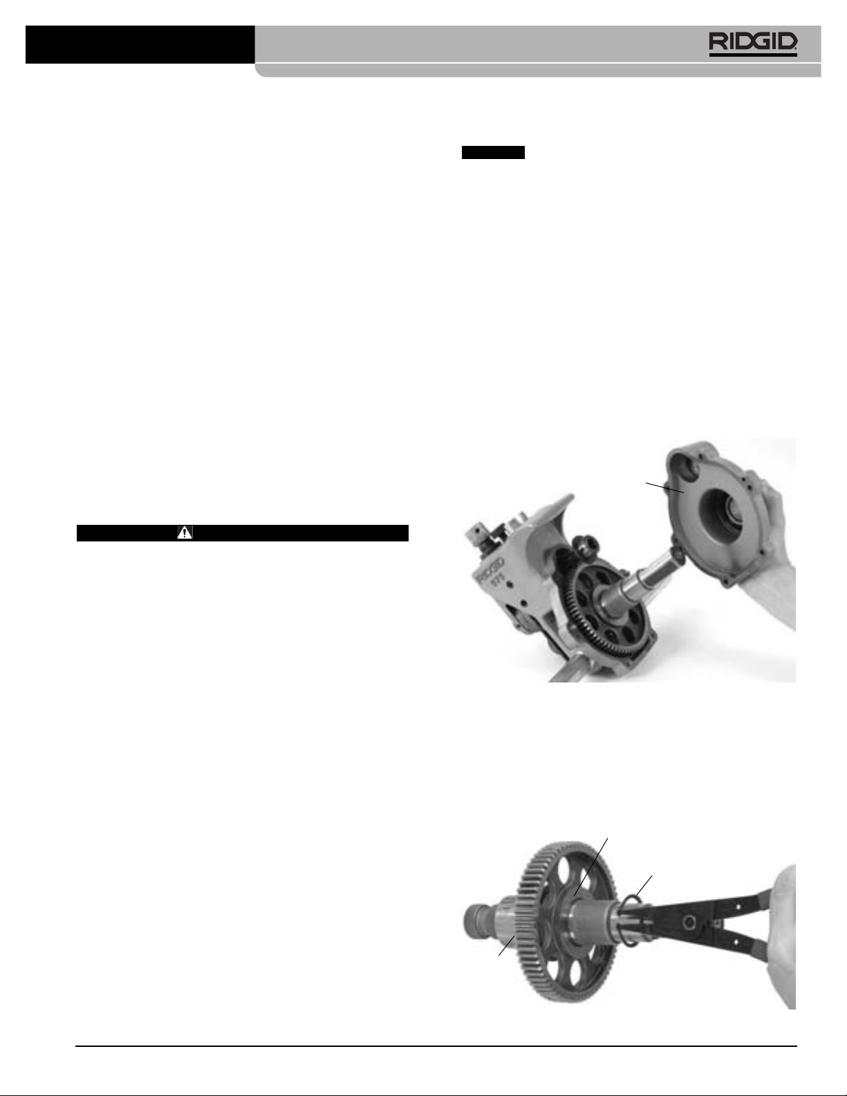
Ranuradora a rodillos combinada No. 975
pués de que el tornillo de ajuste alcance la parte
superior de la ranuradora, porque esto podría dañar
el tornillo de ajuste. Permita que la ranuradora efectúe por lo menos otras dos vueltas completas alrededor del tubo después de que el tornillo de ajuste
haya alcanzado la parte superior de la ranuradora,
para asegurar una profundidad de ranura pareja.
8. Cambie el trinquete al tornillo de alimentación. Sujete
la ranuradora con firmeza. Gire el tornillo de alimentación hacia la izquierda y retraiga el rodillo ranurador para permitir la extracción de la ranuradora
fuera del tubo. No vaya a dejar caer la ranuradora.
9. Revise la ranura.
• Asegure que la ranura esté completamente for-
mada.
• Chequee el diámetro de la ranura y que cumple
con la especificaciones.
• Chequee cualquier otro asunto requerido por el
fabricante del acoplamiento.
Si detecta cualquier problema, la ranura es iservible.
Instrucciones de mantenimiento
Reemplazo de los juegos de rodillos
AVISO
que el rodillo de accionamiento y el de ranurado tienen la
misma denominación. Si no corresponden, se labrarán
ranuras ndebidas que causarán fugas.
Desmonte la Ranuradora a Rodillos del Accionamiento
Motorizado o de la Roscadora y póngala en un banco de
trabajo estable.
Herramientas necesarias:
• Llave hexagonal de
• Llave hexagonal de 3/32pulg.
• Alicate de 0,70 pulg. para el aro de fijación externo
Extracción e instalación del rodillo de accionamiento
1. Extraiga los 6 tornillos que sujetan la cubierta trasera
2. Extraiga la cubierta trasera
Cuando reemplace algún rodillo, cerciórese de
3
/8pulg.
de la carcasa.
(Figura 18)
Cubierta
trasera
.
ADVERTENCIA
Antes de hacerle cualquier mantenimiento o
ajustes al equipo, asegure que el interruptor del
accionamiento motorizado se encuentre en OFF y
la máquina esté desenchufada.
Lubricación
Lubrique la Ranuradora No. 975 una vez al mes con
grasa multiuso.
• Los orificios para el engrase se encuentran en el
costado de la base en el lado donde se para el
operario, en la parte delantera del bloque corredizo y en el extremo del eje del rodillo ranurador
(vea la Figura 2)
. Aplique grasa hasta que asome
una pequeña cantidad.
• Aplique una capa delgada de grasa sobre el torni-
llo de alimentación.
• La caja de engranajes de la Ranuradora de Rodi-
llos No. 975 viene engrasada de por vida y no
necesita lubricación salvo que haya sido abierta.
Para mayor información sobre el mantenimiento, vea la
sección Inspección de la Ranuradora a Rodillos.
Limpieza
Limpie las estrías del eje de alimentación con una escobilla
metálica todos los días o más a menudo si fuera necesario.
Figura 18 – Extracción de la cubierta trasera
3. Extraiga el piñón.
4. Extraiga el ensamble del eje de accionamiento
desde la parte trasera de la Ranuradora No. 975.
5. Extraiga el aro de retención del eje de accionamiento y retire el engranaje
Arandela
de
empuje
(vea la Figura 19)
Engranaje
Aro de retención
.
Figura 19 – Extracción del aro de retención
Ridge Tool Company 65
Page 68

Ranuradora a rodillos combinada No. 975
6. Extraiga la llave y luego la arandela de empuje.
7. Coloque la arandela en el nuevo eje de accionamiento.
8. Introduzca la llave e instale el engranaje.
9. Instale el aro de retención en la ranura del eje de
accionamiento.
10. Coloque el conjunto del eje de accionamiento en el
alojamiento principal.
11. Es posible que la caja de engranajes haya perdido
grasa durante el cambio de ejes. Asegure que los
cojinetes y los dientes del engranaje estén cubiertos
de suficiente grasa de uso general.
12. Introduzca el piñón y vuelva a colocar la cubierta
trasera. Apriete los tornillos con una torsión de 12 a 16
pies*lbs.
Alojamiento principal
Eje de
accionamiento
Piñón
Arandela
de empuje
Figura 20 – Piezas y partes de la Ranuradora a Rodillos
Llave
No. 975
Tornillo de
retención
Engranaje
Tornillos
Cubierta
trasera
Extracción e instalación del rodillo de ranurado
1. Extraiga el tornillo de fijación que sujeta el eje del rodillo de ranurado.
2. Jale el eje del rodillo de ranurado fuera del bloque
corredizo y extraiga el rodillo de ranurado y la arandela
de empuje.
Alojamiento principal
Bloque
corredizo
Tornillo de
fijación
Arandela
de empuje
Rodillo
de
ranurado
3. Coloque la arandela de empuje y el nuevo rodillo de
ranurado en el bloque corredizo. Asegure que el aro
de retención interno en el rodillo de ranurado sea lo
que quede más cercano al alojamiento principal y que
el rodillo de ranurado se encuentre entre la arandela de empuje y el alojamiento principal.
4. Vuelva a colocar el eje del rodillo de ranurado y el
tornillo de fijación.
5. Revise la alineación entre el rodillo de ranurado y el
rodillo de alimentación. Si no están alineados, chequee la orientación del rodillo de ranurado y la arandela de empuje.
6. Engrase el conjunto según la sección
Lubricación
.
Accesorios
ADVERTENCIA
Los siguientes productos RIDGID son los únicos
aptos para funcionar con la Ranuradora a Rodillos
No. 975. Los accesorios de otras máquinas pueden
resultar peligrosos si se usan con esta Ranuradora.
Para evitar lesiones de gravedad, sólo use los accesorios hechos y recomendados específicamente
para usarse con la Ranuradora No. 975 como los
que se listan a continuación.
No. en el
catálogo Descripción
41855 Accionamiento Motorizado No. 300, 115V, 25 a 60 Hz, 38 rpm
75075 Accionamiento Motorizado No. 300, 115V, 23 a 60 Hz, 57 rpm
42360 Soporte No. 1206 para el Accionamiento Motorizado No. 300
66947 Compact 300, 115V 50/60 Hz 38 rpm
73447 Compact 300, 115V 50/60 Hz 52 rpm
67662 Brazo adaptador para la Compact 300
67657 Soporte plegable No. 250 para la Compact 300
72037 Prensa de tornillo portátil con cadena y trípode N. 460
56662 Soportatubos en “V” para tubería en altura VJ-99
76822 Cinta mide-diámetros (medición inglesa)
76827 Cinta mide-diámetros (sistema métrico)
30708 Extensión, accionamiento de 1/2", con bloqueo
30703 Trinquete, accionamiento de 1/2", de ángulo recto
32833 Rodillos de ranurado y de accionamiento la tubos de cobre
tipos K, L, M y DWV de 2 a 8 pulgs.
Almacenamiento de la máquina
ADVERTENCIA
del alcance de niños y personas no capacitadas para
hacer funcionar este equipo de ranurado. Esta máquina
puede causar lesiones de gravedad en manos de inexpertos.
Guarde la máquina bajo llave fuera
Figura 21
Servicio y reparaciones
ADVERTENCIA
El servicio o reparaciones inadecuados pueden
tornar la máquina en una insegura de operar.
Las "Instrucciones de Mantenimiento" cubren la mayoría
Ridge Tool Company66
Page 69

Ranuradora a rodillos combinada No. 975
de los servicios que requiere esta máquina. Cualquier
problema que no haya sido comentado en esta sección
debe ser resuelto únicamente por un técnico autorizado
por RIDGID.
La máquina debe llevarse a un Servicentro Autorizado
Independiente RIDGID o ser devuelta a la fábrica.
Sólo deben usarse piezas de recambio idénticas cuando
se le hace mantenimiento a esta máquina. Si no se
siguen estas instrucciones, pueden producirse lesiones
graves.
Si tiene cualquier pregunta relativa al servicio o reparación de esta máquina, llame o escriba a:
Ridge Tool Company
Technical Service Department
400 Clark Street
Elyria, Ohio 44035-6001
Teléfono: (800) 519-3456
E-mail: TechServices@ridgid.com
Para obtener el nombre y la dirección del Servicentro
Autorizado más cercano, llame al (800) 519-3456 o
visítenos en www.RIDGID.com
Tabla I. Especificaciones para ranuras a rodillo estándar en tubos
de dimensiones IPS
¡NOTA! Todas las dimensiones se expresan en pulgadas
DIMENSIÓN Ø DEL ESPESOR ASIENTO ANCHO DE Ø DE LA PROFUNDIDAD
NOMINAL TUBO MÍN. DE EMPAQUETADURA LA RANURA RANURA NOMINAL DE
DEL TUBO ext. TOL PARED. +0,015/-0,030 +0,030/-0,015 ext. TOL RANURA (Ref.) (2)
1
4
1
/
1,660 +0,016 0,065 0,625 0,344 1,535 +0,000 0,063
-0,016 -0,015
1
2
1
/
1,900 +0,016 0,065 0,625 0,344 1,775 +0,000 0,063
-0,016 -0,015
(1)
2
2,375+0,024 0,065 0,625 0,344 2,250 +0,000 0,063
-0,016 -0,015
1
(1)
2
2
/
2,875+0,029 0,083 0,625 0,344 2,720 +0,000 0,078
-0,016 -0,015
(1)
3
3,50
+
0,030 0,083 0,625 0,344 3,344 +0,000 0,078
-0,018 -0,015
1
(1)
2
3
/
4,00
+
0,030 0,083 0,625 0,344 3,834 +0,000 0,083
-0,018 -0,015
(1)
4
4,50
+
0,035 0,083 0,625 0,344 4,334 +0,000 0,083
-0,020 -0,015
(1)
5
5,563+0,056 0,109 0,625 0,344 5,395 +0,000 0,084
-0,022 -0,015
(1)
6
6,625+0,050 0,109 0,625 0,344 6,455 +0,000 0,085
-0,024 -0,015
1. Según la norma AWWA C606-87.
2. La Profundidad Nominal de Ranura se entrega como una dimensión de referencia. No use la profundidad de ranura para determinar si la ranura es aceptable.
T A BC D
Tabla II. Espesores máximos y mínimos de pared de tubo
¡NOTA! Todas las dimensiones están dadas en pulgadas.
Dimensión CARBONO O DE ALUMINIO INOXIDABLE TUBERÍA DE PVC
del tubo
1
1
/4" 0,065 0,140 0,065 0,140 0,140 0,140
1
1
/2" 0,065 0,145 0,065 0,145 0,145 0,200
2" 0,065 0,154 0,065 0,154 0,154 0,154
1
2
/2" 0,083 0,203 0,083 0,188 0,203 0,276
3" 0,083 0,216 0,083 0,188 0,216 0,300
1
3
/2" 0,083 0,226 0,083 0,188 0,226 0,300
4" 0,083 0,237 0,083 0,188 0,237 0,300
5" 0,109 0,258 0,109 0,188 0,258 0,300
6" 0,109 0,280 0,109 0,188 0,280 0,300
TUBERÍA DE ACERO DE TUBERÍA DE ACERO
Espesor pared del tubo Espesor pared del tubo Espesor pared del tubo
Min. Max. Min.
Max. Min. Max.
Ridge Tool Company 67
Page 70

Ranuradora a rodillos combinada No. 975
Tabla III. Especificaciones para ranuras en cobre
1 2 345678
AB CDT
Asiento Ancho Ø Prof. Tolerancia Tolerancia
Dimensión Ø ext. Tubo empaque- de la de la de la mín. máx.
nominal tadura ranura ranura ranura grosor Ø
pulgadas A +0,03 +0,00 Ref.
Básico Tolerancia ±0,03 –0,000 –0,02
2 2,125 ±0,002 0,610 0,300 2,029 0,048 DWV 2,220
2
21/
2,625 ±0,002 0,610 0,300 2,525 0,050 0,065 2,720
3 3,125 ±0,002 0,610 0,300 3,025 0,050 DWV 3,220
4 4,125 ±0,002 0,610 0,300 4,019 0,053 DWV 4,220
5 5,125 ±0,002 0,610 0,300 5,019 0,053 DWV 5,220
6 6,125 ±0,002 0,610 0,300 5,999 0,063 DWV 6,220
8 8,125 +0,002/-0,004 0,610 0,300 7,959 0,083 DWV 8,220
1. La Profundidad Nominal de Ranura se entrega como una dimensión de referencia. No use la profundidad de ranura para determinar si la ranura
es aceptable.
1
pared abocinado
Detección de averías
PROBLEMA POSIBLES CAUSAS SOLUCIÓN
Ranura muy angosta o
muy ancha.
La ranura no está perpendicular al eje del tubo.
El tubo no avanza
durante el ranurado, o
bien, la ranuradora no
avanza sobre el tubo.
Rodillo de ranurado y/o eje de accionamiento
desgastado.
Tubo torcido.
Extremo del tubo no se encuentra en ángulo recto
respecto al eje del tubo.
Tubo y eje de accionamiento no están paralelos.
El eje del tubo no se ha desviado en
relación con el eje del rodillo de accionamiento.
Estrías del rodillo de accionamiento tapadas o
planas por el desgaste.
Tornillo de alimentación no apretado.
Trinquete se está girando en la dirección equivocada.
Tubo tiene demasiadas escamas en su interior.
Costura soldada es demasiado grande.
No se le está aplicando presión al tubo.
El extremo del tubo no está cortado en ángulo
recto o tiene rebabas.
Tornillo de alimentación demasiado apretado.
1
/2grado en
Reemplace el rodillo de ranurado y/o eje de
accionamiento.
El tubo debe ser recto.
Corte el extremo del tubo en 90 grados.
Ajuste el soporte para que el tubo esté paralelo.
Desvíe el tubo en
Limpie o reemplace el rodillo de accionamiento.
Apriete el tornillo de alimentación con el trinquete
después de cada revolución del tubo, como se
indica.
Gire el trinquete en el sentido correcto.
Limpie el interior del tubo.
Amole la costura soldada 2 pulgadas desde el
extremo del tubo.
Presione el tubo con su mano
Prepare el extremo del tubo como se debe.
Gire el tornillo de alimentación sólo de a 1/4de vuelta.
1
/2grado.
(vea la Figura 10)
.
El tubo se abocina o
acampana en el extremo
ranurado.
Tubo y eje de accionamiento no están paralelos.
Tornillo de alimentación demasiado apretado.
Ridge Tool Company68
Ajuste el soporte para que el tubo quede paralelo al
eje de accionamiento.
Sólo apriete el tornillo de alimentación de a 1/4de
vuelta.
Page 71

Ranuradora a rodillos combinada No. 975
Detección de averías
(cont.)
PROBLEMA POSIBLES CAUSAS SOLUCIÓN
El tubo se balancea hacia
atrás y hacia delante en
el eje del rodillo de
accionamiento durante el
ranurado.
El tubo se mece para
atrás y para adelante
sobre el eje del rodillo de
accionamiento durante el
ranurado.
La Ranuradora no labra
una ranura en el tubo.
Tubo está torcido.
Extremo del tubo no está e ángulo recto con
respecto al eje del tubo.
El soportatubos está puesto demasiado cerca del
extremo del tubo.
Extremo del tubo aplanado o dañado.
Puntos duros en el material del tubo mismo o las
soldaduras son más duras que el tubo.
Alimentación del rodillo de ranurado muy lenta.
Velocidad del accionamiento motorizado excede
las 57 rpm.
Soportatubos mal ubicados.
Se excedió el espesor máximo de pared de tubo.
Material del tubo demasiado duro.
Tornillo de ajuste no se ha regulado.
Accionamiento motorizado no entrega el par de
torsión mínimo.
Emplee un tubo recto.
Corte el extremo del tubo en ángulo recto.
Acerque el soportatubos, situélo según instrucciones.
Corte el extremo del tubo dañado.
Use otro tubo.
Alimente el rodillo ranurador más rápidamente
sobre el tubo.
Reduzca la velocidad a 57 rpm.
Sitúe el portatubos donde corresponda según las
instrucciones.
Consulte la tabla de espesores máximos de
pared de tubos.
Reemplace el tubo.
Regule la profundidad.
Emplee un Accionamiento Motorizado No. 300
de RIDGID de 38 rpm
La Ranuradora no labra la
ranura según diámetro
requerido.
El tubo se resbala o
patina sobre el rodillo
de accionamiento.
Ranuradora no hace
girar el tubo durante el
ranurado.
El tubo se levanta o inclina la Ranuradora hacia
atrás.
El diámetro máximo del tubo excede lo tolerado.
Tornillo de ajuste de la profundidad en posición
incorrecta.
Tubo demasiado duro.
Velocidad del rodillo de ranurado muy lenta.
Estrías del accionamiento tapadas de metal o
aplanadas por el desgaste.
Accionamiento motorizado no entrega el par de
torsión mínimo.
Portaherramientas no se ha cerrado firmemente
sobre los planos del eje de accionamiento.
Soportatubos mal situado.
Use tubería del diámetro correcto.
Ajuste la profundidad.
Use otro tipo de tubo.
Alimente el rodillo ranurador más rápidamente
sobre el tubo.
Limpie o recambie el rodillo de accionamiento.
Emplee un Accionamiento Motorizado No. 300
de RIDGID de 38 rpm
Cierre bien el portaherramientas.
Pare el portatubos como y donde se debe.
Ridge Tool Company 69
Page 72

975
975 KOMBI Rollnutgerät
Page 73

975 KOMBI Rollnutgerät
Inhaltsverzeichnis
Sicherheitssymbole ........................................................................................................................................................................72
Allgemeine Sicherheitsvorschriften7
Sicherheit im Arbeitsbereich ........................................................................................................................................................72
Elektrische Sicherheit....................................................................................................................................................................72
Persönliche Sicherheit ..................................................................................................................................................................73
Sachgemäßer Umgang mit dem Werkzeug ..................................................................................................................................73
Wartung ........................................................................................................................................................................................73
Spezielle Sicherheitshinweise
Sicherer Umgang mit dem Rollnutgerät ........................................................................................................................................74
Sicherer Umgang mit dem Rollnutgerät, wenn es zusammen mit einem Kraftantrieb/einer
Gewindeschneidmaschine verwendet wird ..................................................................................................................................74
Sicherer Umgang mit dem Rollnutgerät, wenn es vor Ort verwendet wird ..................................................................................74
Beschreibung, technische Daten und Standardausstattung
Beschreibung ................................................................................................................................................................................74
Technische Daten ........................................................................................................................................................................75
Standardausstattung ....................................................................................................................................................................75
Inspektion des Rollnutgeräts..........................................................................................................................................................75
Einrichtung des Geräts und des Arbeitsbereichs für Anwendungen mit dem Kraftantrieb
Montage des 975 KOMBI Rollnutgerät auf einen Kraftantrieb RIDGID 300 ................................................................................77
Montage des 975 KOMBI Rollnutgerät auf eine Gewindeschneidmaschine RIDGID 1233 oder 300 Kompakt............................77
Vorbereitung abschließen ............................................................................................................................................................78
Vorbereitung des Rohrs ................................................................................................................................................................79
Vorbereitung des Rohrs im Rollnutgerät ......................................................................................................................................80
Betrieb des 975 KOMBI Rollnutgerät mit einem Kraftantrieb/einer Gewindeschneidmaschine
Einstellen/Messen des Nutdurchmessers ....................................................................................................................................80
Ausführen der Rollnut ..................................................................................................................................................................81
Einstellen des Nutdurchmessers für Kupferrohrleitungen ............................................................................................................82
Tipps zur Spurführung für das 975 KOMBI Rollnutgerät ..............................................................................................................82
Vorbereitung des Geräts und des Arbeitsbereichs für Anwendungen vor Ort
Vorbereitung des Rohrs ................................................................................................................................................................84
Montage des Rollnutgeräts auf das Rohr......................................................................................................................................84
Betrieb des 975 KOMBI Rollnutgerät vor Ort
Einstellen/Messen des Nutdurchmessers ....................................................................................................................................85
Ausführen der Rollnut ..................................................................................................................................................................86
Wartungsanweisungen
Schmierung ..................................................................................................................................................................................86
Reinigen ........................................................................................................................................................................................87
Auswechseln der Rollensätze ......................................................................................................................................................87
Zubehör ............................................................................................................................................................................................88
Lagerung des Geräts ........................................................................................................................................................................88
Wartung und Reparatur ..................................................................................................................................................................88
Tabelle I. Technische Daten für Standard-Rollnut........................................................................................................................89
Tabelle II. Maximale und minimale Wanddicke des Rohrs ..........................................................................................................89
Tabelle III. Technische Daten für Rollnut in Kupferrohren ..........................................................................................................90
Fehlersuche ................................................................................................................................................................................90-91
71 Ridge Tool Company
Page 74

975 KOMBI Rollnutgerät
Sicherheitssymbole
Wichtige Sicherheitshinweise werden in dieser Bedienungsanleitung und auf dem Produkt mit bestimmten Sicherheitssymbolen und
Warnungen gekennzeichnet. Dieser Abschnitt enthält Erläuterungen zu diesen Warnhinweisen und Symbolen.
Dies ist das allgemeine Gefahren-Symbol. Es weist auf mögliche Verletzungsgefahren hin. Beachten Sie alle Hinweise mit diesem
Symbol, um Verletzungs- oder Lebensgefahr zu vermeiden.
GEFAHR
WARNUNG
ACHTUNG
HINWEIS
Dieses Symbol bedeutet, dass die Bedienungsanleitung sorgfältig durchzulesen ist, bevor das Gerät in Betrieb genommen wird.
Die Bedienungsanleitung enthält wichtige Informationen für den sicheren, ordnungsgemäßen Gebrauch des Gerätes.
Dieses Symbol bedeutet, dass bei der Arbeit mit diesem Gerät immer eine Schutzbrille mit Seitenschutz oder ein Augenschutz
zu verwenden ist, um Augenverletzungen zu vermeiden.
Dieses Symbol weist auf das Risiko hin, dass Finger und Hände zwischen den Nutrollen gequetscht werden können.
Dieses Symbol weist auf das Risiko hin, dass Hände, Finger, Beine, Kleider und andere Gegenstände von den drehenden Wellen
erfasst werden und/oder sich um diese wickeln können, was zu Verletzungen durch Zerquetschen oder Aufprall führen kann.
Dieses Symbol zeigt an, dass kein Bohrer, Schlagwerkzeug oder anderes Elektrowerkzeug zum Antrieb dieses Geräts verwendet
werden sollte, wenn es vor Ort eingesetzt wird.
Dieses Symbol weist auf das Risiko hin, dass das Gerät umkippen kann, was zu Verletzungen durch Aufprall oder Zerquetschen
führen kann.
Dieses Symbol bedeutet, dass immer ein Fußschalter verwendet werden sollte, wenn eine Gewindeschneidmaschine/ein
Kraftantrieb verwendet wird.
Dieses Symbol bedeutet, dass man einen Schutzhelm tragen muss, wenn über dem Kopf gearbeitet wird, um das Risiko von
Kopfverletzungen zu verringern.
GEFAHR weist auf eine gefährliche Situation hin, die ohne entsprechende Sicherheitsvorkehrungen zu Lebensgefahr
oder schweren Verletzungen führt.
WARNUNG weist auf eine gefährliche Situation hin, die ohne entsprechende Sicherheitsvorkehrungen zu Lebensgefahr
oder schweren Verletzungen führen kann.
ACHTUNG weist auf eine gefährliche Situation hin, die ohne entsprechende Sicherheitsvorkehrungen zu kleineren bis
mittelschweren Verletzungen führen kann.
HINWEIS kennzeichnet Informationen, die sich auf den Schutz des Eigentums beziehen.
Allgemeine
Sicherheitsvorschriften
WARNUNG
Bitte lesen Sie diese Anweisungen sorgfältig durch. Die
Nichtbeachtung der nachfolgenden Anweisungen kann zu
Stromschlag, Brand und/oder schweren Verletzungen führen.
BEWAHREN SIE DIESE ANWEISUNGEN AUF!
Der im folgenden Text verwendete Begriff „Elektrowerkzeug“
bezieht sich auf netzbetriebene Elektrowerkzeuge (mit
Netzkabel) und akkubetriebene Elektrowerkzeuge (ohne
Netzkabel).
Sicherheit im Arbeitsbereich
• Halten Sie Ihren Arbeitsbereich sauber, und sorgen Sie
für eine gute Beleuchtung. Unaufgeräumte und unzurei-
chend beleuchtete Arbeitsbereiche erhöhen das Unfallrisiko.
• Betreiben Sie Elektrowerkzeuge nicht in Umgebungen
mit erhöhter Explosionsgefahr, in denen sich leicht entflammbare Flüssigkeiten, Gase oder Staub befinden.
Elektrowerkzeuge erzeugen im Betrieb Funken, durch die
sich Staub oder Brandgase leicht entzünden können.
• Sorgen Sie beim Betrieb eines Elektrowerkzeugs dafür,
dass sich keine Kinder oder sonstige Unbeteiligte in
dessen Nähe befinden. Bei Unachtsamkeit kann die
Kontrolle über das Werkzeug verloren gehen.
• Halten Sie die Fußböden trocken und frei von
Materialien, auf denen man ausrutschen kann, wie zum
Beispiel Öl. Rutschige Fußböden erhöhen das Unfallrisiko.
• Schützen Sie den Arbeitsbereich oder sperren Sie ihn ab,
wenn das Werkstück über die Maschine hinaus ragt.
Eine Schutzvorrichtung oder ein Geländer in einem
Mindestabstand von ca. 1 m um das Werkstück, verringert
das Risiko, von diesem erfasst zu werden.
Elektrische Sicherheit
• Die Stecker des Elektrowerkzeugs müssen passend zur
verwendeten Steckdose sein. Nehmen Sie niemals
Veränderungen am Stecker vor. Verwenden Sie keine
Adapterstecker in Kombination mit schutzgeerdeten
Geräten. Unveränderte Stecker und passende Steckdosen
verringern die Gefahr eines Stromschlags.
• Vermeiden Sie Körperkontakt mit geerdeten
Oberflächen, wie Rohren, Heizungen, Herden und
Kühlschränken. Es besteht eine erhöhte
Stromschlaggefahr, wenn Ihr Körper geerdet ist.
• Halten Sie Elektrowerkzeuge von Regen und Nässe
fern. Das Eindringen von Wasser in ein Elektrowerkzeug
erhöht die Stromschlaggefahr.
Ridge Tool Company72
Page 75

975 KOMBI Rollnutgerät
• Das Netzkabel darf nicht für anderweitige Zwecke missbraucht werden. Verwenden Sie es niemals zum Tragen
oder Ziehen des Werkzeugs oder zum Herausziehen
des Steckers. Halten Sie das Kabel von Hitze, Öl, scharfen Kanten und beweglichen Geräteteilen fern.
Beschädigte oder verwickelte Kabel erhöhen die
Stromschlaggefahr.
• Wenn Sie mit einem Elektrowerkzeug im Freien arbeiten,
verwenden Sie nur Verlängerungskabel, die für die
Verwendung im Freien geeignet sind. Die Verwendung
eines geeigneten Verlängerungskabels für den Gebrauch im
Freien verringert die Gefahr eines Stromschlags.
• Wenn Sie ein Elektrowerkzeug in feuchter Umgebung
einsetzen müssen, verwenden Sie eine
Stromversorgung mit Erdschlussunterbrecher (RCD).
Die Verwendung eines Fehlerstromschutzschalters (FISchutzschalters) verringert die Gefahr eines
Stromschlags.
Persönliche Sicherheit
• Seien Sie beim Betrieb eines Elektrowerkzeugs immer
aufmerksam und verantwortungsbewusst. Verwenden
Sie ein Elektrowerkzeug nicht unter Einfluss von
Drogen, Alkohol oder Medikamenten. Durch einen kurzen
Moment der Unaufmerksamkeit können Sie sich selbst oder
anderen erhebliche Verletzungen zufügen.
• Tragen Sie immer Ihre persönliche Schutzkleidung.
Tragen Sie stets einen Augenschutz. Das Tragen einer
Schutzausrüstung, wie Staubmaske, rutschfeste
Sicherheitsschuhe, Schutzhelm oder Gehörschutz verringert
das Risiko von Verletzungen und ist daher unbedingt erforderlich.
• Verhindern Sie, dass Elektrowerkzeuge unbeabsichtigt
eingeschaltet werden. Vergewissern Sie sich immer,
dass sich der Schalter in der Aus-Stellung befindet,
bevor Sie ein Elektrowerkzeug anheben, tragen oder
an die Stromquelle bzw. einen Akku anschließen. Wenn
Sie beim Tragen des Gerätes den Finger am Schalter haben
oder das Gerät eingeschaltet an die Stromversorgung anschließen, kann dies zu Unfällen führen.
• Entfernen Sie sämtliche Einstellwerkzeuge oder
Schraubenschlüssel, bevor Sie das Gerät einschalten.
Ein Werkzeug oder Schlüssel, der sich in einem drehenden
Geräteteil befindet, kann zu Verletzungen führen.
• Überschätzen Sie sich nicht. Achten Sie darauf, dass Sie
stets einen festen Stand haben und das Gleichgewicht
halten. Dadurch können Sie das Gerät in unerwarteten
Situationen besser kontrollieren.
• Tragen Sie angemessene Kleidung. Tragen Sie keine
weiten Kleidungsstücke oder Schmuck. Halten Sie
Haare, Kleidung und Handschuhe von beweglichen
Teilen fern. Weite Kleidung, Schmuck oder lange Haare
können von bewegten Teilen erfasst werden.
• Wenn Staubabsaug- und Staubauffangeinrichtungen
montiert werden können, vergewissern Sie sich, dass
diese angeschlossen sind und vorschriftsmäßig verwendet werden. Durch Verwendung von
Staubauffangeinrichtungen können die durch Staub entstehenden Gefahren erheblich reduziert werden.
Sachgemäßer Umgang mit dem Werkzeug
• Überbeanspruchen Sie das Werkzeug nicht. Verwenden
Sie immer ein für den Einsatzbereich geeignetes
Werkzeug. Mit dem richtigen Werkzeug können Sie Ihre
Arbeit effektiver und sicherer ausführen.
• Verwenden Sie das Elektrowerkzeug nicht, wenn es
nicht über einen Schalter AN- und AUSGESCHALTET
werden kann. Ein Werkzeug, das sich nicht über einen
Schalter ein- und ausschalten lässt, stellt eine
Gefahrenquelle dar und muss repariert werden.
• Ziehen Sie den Stecker aus der Steckdose, oder nehmen
Sie den Akku aus dem Werkzeug, bevor Sie
Geräteeinstellungen vornehmen, Zubehörteile wechseln oder das Gerät weglegen. Durch solche
Vorsichtsmaßnahmen wird der unbeabsichtigte Start des
Werkzeugs verhindert.
• Bewahren Sie unbenutzte Werkzeuge außerhalb der
Reichweite von Kindern auf, und lassen Sie Personen,
die mit dem Werkzeug nicht vertraut sind oder diese
Anweisungen nicht gelesen haben, das Werkzeug nicht
benutzen. Werkzeuge sind gefährlich, wenn Sie von uner-
fahrenen Personen benutzt werden.
• Werkzeuge müssen regelmäßig gewartet werden. Stellen
Sie sicher, dass sich alle beweglichen und festen Teile
in der richtigen Position befinden, keine Teile gebrochen
sind oder sonstige Fehler vorliegen, um den reibungslosen Betrieb des Werkzeuges sicherzustellen. Bei
Beschädigungen muss das Werkzeug vor einer erneuten
Verwendung zunächst repariert werden. Viele Unfälle
werden durch schlecht gewartete Werkzeuge verursacht.
• Verwenden Sie für das Werkzeug nur die empfohlenen
Zubehörteile. Sorgfältig gepflegte Schneidwerkzeuge mit
scharfen Schneidkanten verklemmen seltener und sind
leichter zu führen.
• Halten Sie die Griffleisten trocken, sauber und frei von
Ölen und Fetten. Dadurch können Sie das Werkzeug besser bedienen.
Wartung
• Lassen Sie Ihr Werkzeug nur von qualifiziertem
Fachpersonal und nur mit Original-Ersatzteilen reparieren. Dadurch bleibt die Sicherheit des Werkzeugs gewähr-
leistet.
Spezielle Sicherheitshinweise
WARNUNG
Dieser Abschnitt enthält wichtige Sicherheitshinweise,
die speziell für dieses Werkzeug gelten.
Lesen Sie diese Sicherheitsvorkehrungen sorgfältig
durch, bevor Sie mit dem 975 KOMBI Rollnutgerät
arbeiten, um das Risiko schwerer Verletzungen zu
reduzieren.
BEWAHREN SIE DIESE ANWEISUNGEN
SORGFÄLTIG AUF!
Bei Fragen wenden Sie sich an die Abteilung Technischer
Kundendienst bei Ridge Tool unter D: 0800- 5888076 oder
A: 0800-677221 oder ridgid.germany@emerson.com.
Ridge Tool Company 73
Page 76

975 KOMBI Rollnutgerät
Sicherer Umgang mit dem Rollnutgerät
• Tragen Sie keine weiten Kleidungsstücke. Lassen Sie
die Hemdsärmel und Jacken zugeknöpft. Greifen Sie
nicht über das Gerät oder das Rohr. Die Kleidung kann
sich im Rohr oder in anderen rotierenden Teilen verfangen, wodurch Sie vom Gerät erfasst und schwer verletzt werden können.
• Halten Sie mit Ihren Händen Abstand zu den Nutrollen.
Nuten Sie das Rohr nicht kürzer als angegeben. Tragen
Sie keine schlecht sitzenden Arbeitshandschuhe. Die
Finger können zwischen den Nutrollen oder zwischen der
Nutrolle und dem Rohr eingequetscht werden.
• Halten Sie mit Ihren Händen Abstand von den
Rohrenden. Greifen Sie nicht in das Innere des Rohrs.
Sie können sich an Graten und scharfen Kanten verfangen
und schneiden. Die Finger können zwischen den Nutrollen
oder zwischen der Nutrolle und dem Rohr eingequetscht werden.
• Achten Sie auf eine ordnungsgemäße Vorbereitung
und Umgang mit dem Rohr. Sie können sich an Graten
und scharfen Kanten verfangen und schneiden.
• Unterstützen Sie das Rohr ordnungsgemäß. Dadurch
wird ein Kippen des Rohrs und des Geräts vermieden.
• Sie müssen diese Bedienungsanleitung, die
Bedienungsanleitung des entsprechenden Kraftantriebs
oder der entsprechenden Gewindeschneidmaschine,
die Installationsanweisungen des Herstellers der Fittings
und die Anweisungen für jedes andere Gerät, das zusammen mit diesem Werkzeug verwendet wird, sorgfältig
durchlesen, bevor Sie mit dem RIDGID
Rollnutgerät arbeiten. Die Nichtbefolgung dieser
Anweisungen kann zu Sachschäden und/oder schweren
Verletzungen führen.
• Tragen Sie immer angemessene persönliche Schutzaus-
rüstung, wenn Sie das RIDGID-975 KOMBI Rollnutgerät
einrichten und mit ihm arbeiten. Zu einer angemessenen
persönlichen Schutzausrüstung gehört immer ein
Augenschutz und kann auch Ausrüstungsgegenstände wie
zum Beispiel gut sitzende Lederhandschuhe, Sicherheitsschuhe mit Stahlkappen und einen Schutzhelm umfassen.
• Verwenden Sie das Rollnutgerät nur zum Nuten von
Rohren mit den in diesen Anweisungen empfohlenen
Größen und Ausführungen. Eine anderweitige
Verwendung und die Änderung des Rollnutgeräts für andere Anwendungen kann das Verletzungsrisiko erhöhen.
®
-975 KOMBI
Sicherer Umgang mit dem Rollnutgerät,
wenn es zusammen mit einem Kraftantrieb/einer Gewindeschneidmaschine
verwendet wird
• Verwenden Sie zusammen mit diesem 975 KOMBI
Rollnutgerät nur den Kraftantrieb RIDGID 300 oder die
Gewindeschneidmaschinen 1233 und 300 Kompakt.
Eine Verwendung anderer Kraftantriebe führt zu einer
unsachgemäßen Vorbereitung und kann zum Kippen des
Geräts oder anderweitigen Problemen führen.
• Verwenden Sie dieses Rollnutgerät nicht mit einem
Kraftantrieb oder einer Gewindeschneidmaschine, die
nicht über einen Fußschalter verfügt. Blockieren Sie
niemals den Fußschalter, so dass dieser den
Kraftantrieb nicht regeln kann. Durch einen Fußschalter
können Sie den Kraftantrieb besser steuern, indem Sie den
Motor durch Abnehmen des Fußes ausschalten. Falls sich
Kleidungsstücke im Gerät verfangen und die Stromzufuhr
zum Motor nicht unterbrochen wird, wird die Kleidung in
das Gerät gezogen. Dieses Gerät hat ein starkes
Drehmoment und kann die Kleidungsstücke mit genügend
Kraft um Ihrem Arm oder andere Körperteile wickeln, um
Knochen zu zerquetschen oder zu brechen oder Ihnen
durch einen Aufprall oder anderweitig Verletzungen zufügen.
• Sowohl der Nutvorgang als auch der Fußschalter müs-
sen von einer Person gesteuert werden. Nicht mit mehr
als einer Person daran arbeiten. Falls sich Kleidungsstücke
verfangen, muss der Bediener den Fußschalter steuern können.
• Nur Kraftantriebe und Gewindeschneidmaschinen mit
einer Drehzahl von 57 U/min oder weniger verwenden.
Bei Geräten mit höherer Drehzahl erhöht sich das
Verletzungsrisiko.
• Vergewissern Sie sich, dass das Rollnutgerät am
Kraftantrieb/Gewindeschneidmaschine ordnungsgemäß
vorbereitet und befestigt ist. Vergewissern Sie sich,
dass der Kraftantrieb, der Ständer, das Rollnutgerät
und das Rohr fest stehen. Dadurch wird ein Kippen des
Geräts und des Rohrs vermieden.
Sicherer Umgang mit dem Rollnutgerät,
wenn es vor Ort verwendet wird
• Arbeiten Sie bei den Anwendungen vor Ort nur mit
Handantrieb. Verwenden Sie keine Elektrogeräte (wie
zum Beispiel Bohrer oder Schlagwerkzeuge), um das
Rollnutgerät anzutreiben, wenn es vor Ort eingesetzt
wird. Die Verwendung von Elektrogeräten kann die Nut
beschädigen und das Verletzungsrisiko erhöhen.
• Bei Arbeiten über Kopf, sollten alle Arbeiter Schutzhelme
tragen und sich nicht in dem darunterliegenden Bereich
bewegen. Dadurch werden schwere Verletzungen vermie-
den, falls das Rollnutgerät, das Rohr oder andere
Gegenstände herunterfallen.
Beschreibung, technische Daten
und Standardausstattung
Beschreibung
Das RIDGID®-975 KOMBI Rollnutgerät schneidet Rollnuten in
Stahl-, Aluminium- und PVC-Rohre und nutet Rohre mit einem
Durchmesser von 1
Aufstellung 40. Es ist ebenfalls konzipiert, Edelstahlrohre von 1
Zoll bis 6 Zoll, Aufstellung 10, und von 11/4Zoll bis 2 Zoll,
Aufstellung 40, zu nuten. Mit einer Änderung des Rollensatzes
kann es auch für Kupferrohre von 2 Zoll - 8 Zoll, Ausführung K,
L, M und DWV angepasst werden. Die Nuten werden gebildet,
indem man das Rohr zwischen die Nutrolle und die Antriebsrolle
schiebt. Die einzig notwendige Einstellung ist die Tiefe der Nut.
Das Gerät ist speziell dafür konzipiert, entweder vor Ort oder
zusammen mit dem Kraftantrieb RIDGID Modell 300 (Modelle mit
38 und 57 U/min) verwendet zu werden. Mit dem entsprechenden
Adapter (Kat. Nr. 67662) kann das Gerät zusammen mit den
Gewindeschneidmaschinen RIDGID Modell 1233 und 300
Kompakt betrieben werden. Zum 975 KOMBI Rollnutgerät gehört
eine patentierte Nuttiefenlehre, die Sie bei der Vorbereitung der
Nut unterstützt, sowie eine patentierte Ausstattung, mit der die
1
/4Zoll bis 6 Zoll, Aufstellung 10 und
1
4
/
Ridge Tool Company74
Page 77

975 KOMBI Rollnutgerät
Spurführung während des Betriebs verbessert wird.
Das 975 KOMBI Rollnutgerät ist ein tragbares Gerät, das für
den gelegentlichen Einsatz auf der Baustelle vorgesehen ist,
und sollte nicht für umfangreiche Arbeiten oder die
Serienproduktion in einer Rohrwerkstatt verwendet werden.
HINWEIS
Bei ordnungsgemäßer Anwendung, schneidet
das 975 KOMBI Rollnutgerät, Nuten von 2 Zoll - 6 Zoll, die in
ihrer Abmessung den Spezifikationen der AWWA C606-06 entsprechen. Die Auswahl der entsprechenden Materialien und
Verfahren für die Verbindung liegt in der Verantwortung des
Systemplaners und/oder Installateurs. Bevor man mit einer
Installation beginnt, sollte eine sorgfältige Bewertung der speziellen Betriebsumgebung, einschließlich der chemischen
Umgebung und der Betriebstemperatur, durchgeführt werden.
Technische Daten
Kapazität............................Stahlrohre von 11/4Zoll – 6 Zoll,
Aufstellung 10 und Aufstellung 40,
mit Austausch der Rollen: 2 Zoll 8 Zoll Kupferrohre, Ausführung K,
L, M & DWV
Nutdurchmesser
Einstellung ........................Einstellschraube und
Nuttiefenlehre
Auslösung..........................Vorschubspindel mit
Montage des Kraftantriebs Kraftantrieb RIDGID 300 (nur
Gewicht ..............................ca. 12,5 kg.
Das 975 KOMBI Rollnutgerät ist durch US-amerikanische und
internationale Patente geschützt, einschließlich der Patente
6.272.895 und 6.591.652.
Gleitstück
Nutrollenwelle
Nutrolle
Antriebswelle
Abdeckplatte
Ratsche
Abbildung 1: 975 KOMBI Rollnutgerät
1
/2Zoll-Ratsche
Modell mit 38 und 57 U/min),
Gewindeschneidmaschine RIDGID 1233 und 300 Kompakt (mit
Adapter)
Vorschubspindel
Einstellschraube
Nuttiefenlehre
Stützarm
Boden
Verlängerung
Standardausstattung
11/4“ – 6 Zoll Aufstellung 10 und 40 Nut- und Antriebsrollen
Ratsche (
Sicherung der Antriebserweiterung
Stützarme
Integrierte Index-Tiefenlehre
1
/2Zoll-Antrieb) mit Entriegelungstaste
Inspektion des Rollnutgeräts
WARNUNG
Kontrollieren Sie Ihr Rollnutgerät vor jedem
Gebrauch und beheben Sie eventuelle Störungen,
um die Verletzungsgefahr durch Zerquetschungen
oder andere Ursachen sowie Schäden am
Rollnutgerät zu vermeiden.
Verwenden Sie dieses Rollnutgerät nicht mit einem
Kraftantrieb/einer Gewindeschneidmaschine, die
nicht über einen Fußschalter verfügt.
1. Falls das Rollnutgerät auf einem Kraftantrieb oder einer
Gewindeschneidmaschine installiert ist, achten Sie darauf,
dass das Gerät nicht eingesteckt ist und dass sich der
Schalter “REV/OFF/FOR” in der Position “OFF” befindet.
Kontrollieren und warten Sie den Kraftantrieb/die Gewindeschneidmaschine wie es in der Bedienungsanleitung für
das jeweilige Gerät angegeben ist. Eine Nichtbeachtung der
ordnungsgemäßen Kontrolle und Wartung des Geräts kann
zu schweren Verletzungen und Sachschäden führen. Achten
Sie darauf, dass ein Fußschalter vorhanden ist und dieser
ordnungsgemäß funktioniert. Verwenden Sie dieses
Rollnutgerät nicht ohne einen Fußschalter.
2. Reinigen Sie das Rollnutgerät einschließlich des Tragegriffs
und der Ratsche, die zur Aktivierung des Rollnutgeräts
verwendet wird, von Öl, Fett oder Schmutz. Dadurch wird
das Verletzungsrisiko verringert, dass Ihnen das
Rollnutgerät oder die Ratsche während des Betriebs aus
der Hand rutscht, und die Inspektion wird erleichtert.
3. Achten Sie darauf, dass die Stützarme fest im Gehäuse des
Rollnutgeräts sitzen.
4. Kontrollieren Sie das Rollnutgerät auf gebrochene, fehlende, falsch angeordnete oder feste Teile oder auf jeden
anderen Zustand, der den sicheren und normalen Betrieb
verhindert. Achten Sie darauf, dass sich die Nutrolle und die
Antriebswelle frei drehen können.
5. Kontrollieren Sie, ob das Schild mit den Warnhinweisen vorhanden und sicher befestigt ist. Bezüglich der Lage des
Warnschilds, siehe Abbildung 2.
6. Wenn die Rändelung der Antriebswelle schmutzig ist, reinigen Sie diese mit einer Drahtbürste. Eine schmutzige
Rändelung kann zu einem Abrutschen des Rohrs und zu
Problemen bei der Spurführung während des Nutens
führen.
7. Kontrollieren Sie die Nutrolle und die Antriebswelle auf
Risse, Verschleiß oder Zeichen von Beschädigung.
Ridge Tool Company 75
Page 78

975 KOMBI Rollnutgerät
Beschädigte Nutrollen und Antriebswellen können zu einem
Rutschen des Rohrs oder zu Nuten in schlechter Qualität
führen oder Störungen während des Betriebs verursachen.
8. Kontrollieren Sie die Ratsche und die Verlängerung auf ordnungsgemäße Funktion. Achten Sie darauf, dass sich die
Ratsche sanft und gleichmäßig in beide Richtungen bewegen lässt. Drücken Sie den Entriegelungsknopf in der Mitte
des Ratschenkopfes und setzen Sie sie auf die
Vorschubspindel. Die Ratsche sollte sicher einrasten. Die
Ratsche sollte ebenfalls sicher in die Verlängerung einrasten und die Verlängerung wiederum sollte sicher in den
Vierkant für manuellen Antrieb an der Rückseite des
Rollnutgeräts einrasten. Dadurch wird verhindert, dass
sich die Ratsche und die Verlängerung während des
Betriebs vom Rollnutgerät lösen. Falls Sie andere Ratschen,
Schraubenschlüssel oder Verlängerungen verwenden, die
nicht in das Rollnutgerät einrasten, müssen Sie darauf
achten, dass diese sich während des Betriebs nicht lösen.
Falls Probleme auftreten, das Gerät solange nicht benutzen,
bis die Probleme behoben worden sind.
9. Schmieren Sie das Rollnutgerät entsprechend den
Wartungsanweisungen in diesem Handbuch. Wischen Sie
überschüssiges Fett vom Rollnutgerät ab.
10. Falls ein anderes Gerät verwendet wird, kontrollieren und
warten Sie es, um sicherzustellen, dass es ordnungsgemäß funktioniert.
Warnschild
Abbildung 2: Warnschild für 975 KOMBI Rollnutgerät
Schmiernippel
Vorbereiten des Geräts und
des Arbeitsbereichs für
Anwendungen mit Kraftantrieb
WARNUNG
Tragen Sie stets einen Augenschutz zum Schutz der
Augen vor Schmutz und Fremdkörpern. Tragen Sie
Sicherheitsschuhe mit Stahlkappe, um die Füße vor
kippenden Werkzeugen und herunterfallenden Rohren
zu schützen.
Verwenden Sie dieses Rollnutgerät nicht mit einem
Kraftantrieb oder einer Gewindeschneidmaschine, die
nicht über einen Fußschalter verfügt. Blockieren Sie niemals den Fußschalter, so dass dieser den Kraftantrieb
nicht regeln kann. Durch einen Fußschalter können Sie
den Kraftantrieb besser steuern, indem Sie den Motor
durch Abnehmen des Fußes ausschalten. Falls sich
Kleidungsstücke im Gerät verfangen und die
Stromzufuhr zum Motor des Kraftantriebs nicht unterbrochen wird, wird die Kleidung in das Gerät hinein
gezogen. Dieses Gerät hat ein starkes Drehmoment
und kann die Kleidungsstücke mit genügend Kraft um
Ihrem Arm oder andere Körperteile wickeln, um
Knochen zu quetschen oder zu brechen oder Ihnen
durch einen Aufprall oder anderweitig Verletzungen
zufügen.
Beachten Sie bitte diese Anweisungen für die
Vorbereitung des Rollnutgeräts und des Arbeitsbereichs,
um die Gefahren von Stromschlag, Feuer, Kippen des
Geräts, Verfangen von Kleidungsstücken, Zerquetschungen und andere Risiken zu verringern und Schäden
am Rollnutgerät zu vermeiden.
1. Suchen Sie sich einen Arbeitsbereich, der folgende
Merkmale aufweist:
• Ausreichende Beleuchtung.
• Keine entflammbaren Flüssigkeiten, Dämpfe oder
Stäube, die sich entzünden können. Sind solche
Gefahrenquellen vorhanden, arbeiten Sie in diesen
Bereichen erst, wenn sie erkannt und beseitigt wurden.
Kraftantriebe und Gewindeschneidmaschinen sind nicht
explosionssicher und können Funken verursachen.
• Ein übersichtlicher, ebener, stabiler und trockener Ort für
alle Geräte und den Bediener. Benutzen Sie das Gerät
nicht, wenn Sie im Wasser stehen.
• Ordnungsgemäß geerdeter Netzanschluss. Eine
Steckdose mit drei Stiften oder eine GFCI-Steckdose ist
u.U. nicht ordnungsgemäß geerdet. Aus
Sicherheitsgründen sollten im Zweifelsfall entsprechende Netzanschlüsse von einem autorisierten
Elektriker überprüft werden.
• Einen freien Weg zum Netzanschluss, sodass eine
mögliche Beschädigung des Netzkabels ausgeschlossen ist.
2. Arbeitsbereich aufräumen, bevor die Geräte vorbereitet werden. Wischen Sie eventuell vorhandenes Öl stets ab.
3. Kontrollieren Sie das Rohr, das genutet werden soll, und
vergewissern Sie sich, dass das 975 KOMBI Rollnutgerät
das richtige Gerät für diese Arbeit ist. Das 975 KOMBI
Rollnutgerät ist konzipiert zum Nuten von Stahl-, Aluminiumund PVC-Rohren der Größe 1
10 und 40. Es ist ebenfalls konzipiert, Edelstahlrohre von 1
1
/4Zoll bis 6 Zoll, Aufstellung
1
Zoll bis 6 Zoll, Aufstellung 10, und von 11/4Zoll bis 2 Zoll,
Aufstellung 40, zu nuten. Wenn der Rollensatz gewechselt
wird, kann es auch zum Nuten von Kupferrohren der Größe
2 Zoll - 8 Zoll, Ausführung K, L, M und DWV verwendet werden.
4
/
Ridge Tool Company76
Page 79

Das 975 KOMBI Rollnutgerät kann für Anwendungen vor
Ort verwendet werden (das Rohr ist eingebaut oder in
einem Schraubstock befestigt) oder zusammen mit einem
Kraftantrieb RIDGID 300 oder einer Gewindeschneidmaschine Kompakt 300 für Anwendungen mit Antrieb auf
der Baustelle. Das 975 KOMBI Rollnutgerät ist nicht für die
Serienproduktion vorgesehen.
Rollnutgeräte für sonstige Anwendungen finden Sie im
Katalog von Ridge Tools, online unter www.RIDGID.eu,
oder durch Anruf beim Technischen Kundendienst von
Ridge Tools unter 0800-5888076.
HINWEIS
und Antriebswelle) sowohl für Rohre aus unlegiertem Stahl als
auch aus Edelstahl kann zu einer Verunreinigung des Edelstahls
führen. Diese Verunreinigung kann zu Korrosion und vorzeitiger
Beschädigung des Rohrs führen. Zur Vermeidung einer
Verunreinigung der Edelstahlrohre durch Eisen verwenden Sie
Rollensätze, die nur für das Rollnuten von Edelstahl vorgesehen
sind. Alternativ kann eine Edelstahlbürste verwendet werden,
um den Rollensatz gründlich zu säubern, wenn man zwischen den
Materialien wechselt.
4. Achten Sie darauf, dass der Kraftantrieb/die
Gewindeschneidmaschine entsprechend dem jeweiligen
Handbuch kontrolliert worden ist. Vergewissern Sie sich,
dass ein Fußschalter vorhanden ist und achten Sie darauf,
dass sich der Schalter “FOR/OFF/REV” in der Position
“OFF” befindet. Die Vorbereitung des Kraftantriebs/der
Gewindeschneidmaschine erfolgt entsprechend den
Anweisungen im jeweiligen Handbuch. Achten Sie darauf, dass das Gerät und der Ständer sicher stehen und
nicht wackeln.
5. Öffnen Sie das Spannfutter des Kraftantriebs/der
Gewindeschneidmaschine vollständig.
6. Vergewissern Sie sich, dass das 975 KOMBI Rollnutgerät
kontrolliert wurde und der entsprechende Rollensatz montiert worden ist.
Die Verwendung der gleichen Rollensätze (Nutrolle
975 KOMBI Rollnutgerät
Abbildung 3: Montage des 975 KOMBI Rollnutgerät in
das Spannfutter des Kraftantriebs 300
Montage des 975 KOMBI Rollnutgerät
auf eine Gewindeschneidmaschine
RIDGID 1233 oder 300 Kompakt
Wenn das 975 KOMBI Rollnutgerät mit einer Gewindeschneidmaschine 1233 oder 300 Kompakt verwendet wird, muss ein
Adaptersatz (Katalognummer 67662) verwendet werden. Dieser
Adaptersatz richtet das Rollnutgerät auf die Gewindeschneidmaschine und den Ständer aus und ermöglicht es, dass der
gesamte Größenbereich genutet werden kann. Versuchen Sie
nicht, das 975 KOMBI Rollnutgerät mit einer anderen
Gewindeschneidmaschine zu verwenden, da dies zum Kippen
oder zu anderen Problemen führen kann.
1. Montieren Sie den Antriebswellenadapter auf die
Antriebswelle des Rollnutgeräts (siehe Abbildung 4). Richten
Sie die Schrauben auf die Platte an der Antriebswelle des
Rollnutgeräts aus und ziehen Sie diese gut fest.
Montage des 975 KOMBI Rollnutgerät
auf einen Kraftantrieb RIDGID 300
1. Falls der zu verwendende Kraftantrieb mit einem Schlitten
oder anderen Anbauteilen ausgestattet ist, nehmen Sie
diese vom Kraftantrieb ab. Achten Sie darauf, dass die
Stützarme des Kraftantriebs vollständig nach vorne zeigen
und in dieser Position fixiert sind.
2. Setzen Sie die Stützarme des Rollnutgeräts auf die
Stützarme des Kraftantriebs und das Ende der
Antriebswelle des Rollnutgeräts in das Spannfutter des
Geräts. Schließen Sie das Spannfutter des Kraftantriebs
und ziehen Sie es auf der Platte der Antriebswelle fest.
Achten Sie darauf, dass die Antriebswelle im Spannfutter
zentriert ist. Drehen Sie das Spannfutterrad (Hammertyp)
wiederholt und kräftig gegen den Uhrzeigersinn, um die
Antriebswelle sicher greifen zu können (Abbildung3).
Ridge Tool Company 77
Abbildung 4: Montage des Antriebswellenadapters
2. Bewegen Sie den Schlitten an der Gewindeschneidmaschine 1233 oder Kompakt 300 so nahe wie möglich an das
Spannfutter des Geräts. Bewegen Sie den
Rohrabschneider, den Entgrater und den Schneidkopf in die
vom Bediener entfernte Position, so dass sie aus dem
Weg sind. Positionieren Sie den Konus des Entgraters im
Schneidkopf.
Page 80

975 KOMBI Rollnutgerät
3. Platzieren Sie die Adapterhalterung über des Ende des
Werkzeugschlitten der 1233 oder 300 Kompakt (wie in
Abbildung 5 gezeigt) und verriegeln sie mit dem beigefügten Stift
Abbildung 5: Installation der Adapterhalterung
4. Setzen Sie die Stützarme des 975 auf die Arme der
Adapterhalterung, wobei der Antriebswellenadapter im
Spannfutter des Geräts sitzt. Schließen Sie das
Spannfutter der Gewindeschneidmaschine und ziehen
Sie es auf dem Antriebswellenadapter fest. Achten Sie
darauf, dass die Antriebswelle im Spannfutter zentriert ist.
Drehen Sie das Spannfutterrad (Hammertyp) wiederholt
und kräftig gegen den Uhrzeigersinn, um die Antriebswelle
sicher greifen zu können.
den Schalter “FOR/OFF/REV” zu haben (auf der gleichen
Seite wie dieser).
• Die Position “ON/OFF” über den Fußschalter zu steuern,
und den Fußschalter schnell loslassen zu können, wenn
es notwendig ist.
• Bequemen Zugang zum Rollnutgerät, zum Rohr und
zur Ratsche zu haben, ohne dabei über das Rollnutgerät
greifen zu müssen.
Abbildung 6: 975 KOMBI Rollnutgerät ordnungsgemäß
auf die Gewindeschneidmaschine 300
Kompakt montiert
Vorbereitung abschließen
1. Den Fußschalter ausrichten, so dass der Bediener den
Kraftantrieb/die Gewindeschneidmaschine, das
Rollnutgerät und das Rohr, das genutet werden soll, kontrollieren kann. Wie in Abbildung 6 gezeigt, sollte die
Position dem Bediener ermöglichen:
• Mit Blick auf das Rollnutgerät zu stehen und Zugriff auf
Abbildung 7: Position des Bedieners
2. Verlegen Sie das Netzkabel in einer vorher klar festgelegten Richtung. Stecken Sie das Stromkabel des
Kraftantriebs mit trockenen Händen in eine ordnungsgemäß geerdete Steckdose ein. Sorgen Sie dafür, dass
sämtliche Anschlüsse trocken bleiben und sich nicht auf
dem Boden befinden. Falls das Netzkabel nicht lang genug
ist, verwenden Sie ein Verlängerungskabel, das:
• In gutem Zustand ist
• Einen Stecker mit drei Stiften hat, gleich dem, der am
Kraftantrieb vorhanden ist
• Für die Verwendung im Außenbereich zugelassen ist
und ein W oder ein W-A in der Bezeichnung des Kabels
enthält (z.B. SOW
• Die mit einem ausreichend großen Querschnitt versehen
sind (14 AWG für 25ʼ oder weniger, 12 AWG für 25ʼ – 50ʼ
Länge). Unterdimensionierte Kabel können sich überhitzen, die Isolierung durchschmelzen oder Feuer oder
sonstige Schäden anrichten.
3. Kontrollieren Sie den Kraftantrieb/die Gewindeschneidmaschine, um eine korrekte Funktion sicherzustellen:
• Schieben Sie den Schalter auf die Position “FOR”
(Forward (Vorwärts)). Drücken Sie den Fußschalter und
lassen Sie ihn wieder los. Vergewissern Sie sich, dass
)
Ridge Tool Company78
Page 81

975 KOMBI Rollnutgerät
sich die Antriebswelle im Gegenuhrzeigersinn dreht, wenn
Sie dem vorderen Spannfutter gegenüber stehen. Falls das
Gerät sich nicht in der richtigen Richtung bewegt, oder der
Betrieb des Geräts mit dem Fußschalter nicht zu steuern
ist, verwenden Sie das Gerät nicht, bevor es repariert
worden ist.
• Drücken Sie den Fußschalter nieder und halten Sie ihn
gedrückt. Überprüfen Sie die Drehzahl des Geräts.
Kontrollieren Sie die beweglichen Teile auf Versatz,
Verklemmen, merkwürdige Geräusche oder andere
ungewöhnliche Bedingungen. Lassen Sie den
Fußschalter los. Falls die Drehzahl 57 U/min überschreitet, das Gerät nicht zum Rollnuten verwenden. Bei
höheren Drehzahlen kann sich das Verletzungsrisiko
erhöhen. Falls ungewöhnliche Bedingungen festgestellt
werden, das Gerät nicht verwenden, bevor es repariert
worden ist.
• Schieben Sie den Schalter auf die Position “REV”
(Reverse (Rückwärts)). Drücken Sie den Fußschalter
und lassen Sie ihn wieder los. Vergewissern Sie sich,
dass sich die Antriebswelle im Uhrzeigersinn dreht,
wenn Sie der Vorderseite des Spannfutters gegenüber stehen. Falls sich das Gerät nicht in der richtigen
Richtung dreht, das Gerät nicht verwenden, bevor es
repariert worden ist.
• Schieben Sie den Schalter auf die Position “OFF”.
Ziehen Sie mit trockenen Händen den Stecker des
Geräts aus der Steckdose.
Vorbereitung des Rohrs
HINWEIS
Beachten Sie immer die speziellen Empfehlungen des
Herstellers des genuteten Verbindungsstücks für die
Vorbereitung des Rohrendes. Eine Nichtbeachtung der
Empfehlungen des Herstellers des genuteten
Verbindungsstücks kann zu einer unsachgemäßen Verbindung
führen und Undichtigkeiten verursachen.
1. Schneiden Sie das Rohr auf die richtige Länge. Achten Sie
dabei auf die Mindestrohrlänge, die für jede Rohrgröße
genutet werden kann (siehe Tabelle A). Wenn das Rohr
kürzer als die Mindestlänge genutet wird, erhöht sich das
Risiko, sich die Finger einzuquetschen oder sich mit den
Kleidern zu verfangen.
Achten Sie darauf, dass das Rohrende rechtwinklig abgeschnitten wird und keine Grate hat. An den Graten können
sich während des Nutvorgangs die Handschuhe oder
Finger verfangen oder schneiden. Das Abschneidverfahren
sowie starke Grate können Einfluss auf die Qualität der
angefertigten Nut und der Spurführung der Nut haben.
Versuchen Sie nicht, ein Rohr zu nuten, dass mit dem
Schweißbrenner abgeschnitten wurde.
2. Alle inneren/äußeren Schweißpunkte, Walzgrate oder
Schweißnähte müssen mindestens bis zu einer Entfernung
von 2 Zoll vom Ende des Rohrs plan geschliffen werden.
Keine ebenen Flächen in den Bereich des Dichtungssitzes
schneiden. Das könnte zu Undichtigkeiten führen.
3. Sämtliche Glühspäne, Schmutz, Rost und sonstige
Verunreinigungen im Abstand von mindestens 2 Zoll vom
Ende des Rohrs entfernen. Verunreinigungen können zu
einem Verstopfen der Antriebsrändelung führen und einen
ordnungsgemäßen Antrieb sowie die Spurführung des
Rohrs während des Nutvorgangs verhindern.
Die folgenden Anweisungen gelten allgemein.
Vorbereitung des Rohrs im Rollnutgerät
1. Vergewissern Sie sich, dass sich der Schalter des
Kraftantriebs/der Gewindeschneidmaschine in der Position
“OFF” befindet.
2. Achten Sie darauf, dass die Abstützung für das Rohr ausreicht, das Sie nuten werden. In TabelleA ist die maximale Länge des Rohrs aufgeführt, das genutet werden soll,
wenn ein einziger Rohrbock verwendet wird. Längere
Rohre sollten mindestens mit zwei Rohrböcken unterstützt
werden. Wenn das Rohr nicht ordnungsgemäß unterstützt
wird, kann das Rohr oder das Rohr und das Gerät kippen
und umfallen. Nuten Sie das Rohr nicht kürzer als die
Mindestlänge.
Nom. Min. Max. Nom. Min. Max.
Abmessung Länge Länge Abmessung Länge Länge
1836 4836
1
4
1
11/
/
2
8 36 41/
8 36 5832
2836 6 A.D. 10 30
2
21/
8 36 6 10 28
3836
2
31/
8 36
Tabelle A: Minimale/Maximale Rohrlänge, die mit einem
Bock genutet werden kann (alle Abmessungen in
Zoll)
3. Stellen Sie die erforderlichen Rohrböcke vor das
Rollnutgerät. Bei Rohrlängen, die von einem einzelnen
Bock gestützt werden, sollte der Bock in einem Abstand von
etwas über der Hälfte der Rohrlänge von der Abdeckplatte
des Rollnutgeräts aufgestellt werden. Bei Rohrlängen, für
die mehr als ein Bock nötig ist, sollten die Böcke in einem
Abstand von
1
/4der Rohrlänge - vom Ende des Rohrs - aufgestellt werden. In manchen Fällen kann es angemessen
sein, mehrere Böcke zu verwenden. Die Höhe des Bocks
sollte so eingestellt sein, dass das Rohr über die
Antriebsrolle passt.
4. Achten Sie darauf, dass die Nutrolle weit genug zurückgezogen ist, damit das Rohr über die Antriebswelle gelegt
werden kann. Drehen Sie die Vorschubspindel ggf. gegen
den Uhrzeigersinn, um die Nutrolle anzuheben.
5. Legen Sie das Rohrende über die Antriebswelle und senken Sie das Rohr auf den/die Rohrbock/-böcke ab. Achten
Sie darauf, dass das Rohr sicher liegt.
Abbildung 8: Aufsetzen des Rohrs auf die Antriebswelle
und bündig mit der Abdeckplatte
2
8 32
Abdeckplatte
Ridge Tool Company 79
Page 82

975 KOMBI Rollnutgerät
6. Stellen Sie das Rohr und den Rohrbock so ein, dass das
Ende des Rohrs bündig mit der Abdeckplatte des
Rollnutgeräts ist und dass die Innenseite des Rohrs die
Oberseite der Antriebswelle berührt (Abbildung 7). Die
Mittellinie des Rohrs und die Mittellinie der Antriebswelle
sollten parallel zu einander sein. Eine Möglichkeit dafür ist,
sowohl das Rohr als auch den Kraftantrieb/die
Gewindeschneidmaschine auszurichten.
7. Verschieben Sie das Rohr und den Rohrbock ein wenig, um
1
ca.
/2Grad (ungefähr 1 Zoll auf eine Länge von ca. 3 m
vom Rollnutgerät) hin zum Bediener. Durch eine ordentliche
Ausrichtung des Rohrs und des Rollnutgeräts wird eine ordnungsgemäße Spurführung des Rohrs während des
Nutvorgangs sichergestellt. (Siehe Abbildung 9).
Mittellinie
des Rohrs
Mittellinie der
Antriebswelle
ca. einem (1) Meter um den Kraftantrieb und das Rohr zu
schaffen. Diese “Sicherheitszone” verhindert, dass andere
Leute unbeabsichtigt mit dem Gerät oder dem Rohr in
Berührung kommen und dies dadurch kippt oder sich ihre
Kleidung in den rotierenden Teilen verfängt.
10. Stecken Sie das Stromkabel des Geräts mit trockenen
Händen in eine ordnungsgemäß geerdete Steckdose ein.
Betrieb des 975 KOMBI Rollnutgerät
mit einem Kraftantrieb/ einer
Gewindeschneidmaschine
WARNUNG
Tragen Sie beim Bedienen des Rollnutgeräts keine
weiten Kleidungsstücke. Lassen Sie die Hemdsärmel
und Jacken zugeknöpft. Greifen Sie nicht über das
Gerät oder das Rohr. Weite Kleidung kann sich in den
rotierenden Teilen verfangen und Quetschverletzungen
verursachen.
Halten Sie mit Ihren Händen Abstand zu den Nutrollen.
Nuten Sie die Rohre nicht kürzer als angegeben. Tragen
Sie keine schlecht sitzenden Arbeitshandschuhe. Die
Finger können zwischen den Nutrollen oder zwischen
der Nutrolle und dem Rohr eingequetscht werden.
Halten Sie mit Ihren Händen Abstand von den
Rohrenden. Greifen Sie nicht in das Innere des Rohrs.
Sie können sich an Graten und scharfen Kanten verfangen und schneiden. Die Finger können zwischen
den Nutrollen oder zwischen der Nutrolle und dem
Rohr eingequetscht werden.
Tragen Sie stets einen Augenschutz zum Schutz der
Augen vor Schmutz und Fremdkörpern. Tragen Sie
Sicherheitsschuhe mit Stahlkappe, um die Füße vor
kippenden Werkzeugen und herunterfallenden Rohren zu
schützen.
Halten Sie sich an die Bedienungsanweisungen, um
die Verletzungsgefahr durch Quetschen, Kippen,
Aufprall oder andere Risiken zu verringern.
1
/2°
Abbildung 9: Versetzen des Rohrs um 1/2 Zoll in
Richtung des Bedieners (übertrieben)
8. Drehen Sie die Vorschubspindel im Uhrzeigersinn, um die
Nutrolle unten in Kontakt mit dem Rohraußendurchmesser
zu bringen. Drehen Sie anschließend die Vorschubspindel
um eine zusätzliche Viertelumdrehung. Eventuell muss
die Einstellschraube gelöst werden (gegen den
Uhrzeigersinn drehen), damit die Nutrolle mit dem Rohr in
Kontakt kommt. Das Rohr und das Rollnutgerät sollten zu
diesem Zeitpunkt gegeneinander gesichert sein.
9. Beurteilen Sie den Arbeitsbereich und entscheiden Sie,
ob Absperrungen erforderlich sind, damit andere Leute
außer dem Bediener von den Geräten und dem Rohr fern
gehalten werden. Schutzeinrichtungen oder Absperrungen
sollten verwendet werden, um einen Mindestabstand von
Einstellen/Messen des Nutdurchmessers
HINWEIS
ten, sollte vor dem Arbeitsbeginn am Anfang des Tages oder
bei Änderung von Rohrgröße, Aufstellung oder Material immer
zuerst eine Probenut angefertigt werden. Die Lehren für die
Einstellung des Nutdurchmessers sind nur ungefähre Angaben,
und der Nutdurchmesser muss zur Bestätigung der genauen
Größe gemessen werden.
1. Vergewissern Sie sich, dass das Gerät und das Rohr ordnungsgemäß vorbereitet ist. Eine unsachgemäße
Vorbereitung des Rohrs kann die genaue Einrichtung der
Nuttiefenlehre beeinflussen. Die Nutrolle sollte das Rohr
berühren.
2. Stellen Sie die Nuttiefenlehre so ein, dass sich der richtige
Ansatz der Lehre unter dem Kopf der Einstellschraube
befindet (Abbildung 10A). Die Nuttiefenlehre ist für die
Ridge Tool Company80
Aufgrund der unterschiedlichen Rohreigenschaf-
Page 83

975 KOMBI Rollnutgerät
Verwendung mit dem Rohr konzipiert. Bei einer
Verwendung mit Kupferrohen, siehe “Einstellen des
Nutdurchmessers für Kupferrohre”.
3. Drehen Sie die Einstellschraube im Uhrzeigersinn, bis der
Kopf den Ansatz der Tiefenlehre berührt. Drehen Sie die
Nuttiefenlehre in die Position “Nuten” (Abbildung 10B).
Falls die Lehre sich nicht in der Position “Nuten” befindet,
verhindert sie das Nuten und kann beschädigt werden.
Abbildung 10A: Den richtigen Ansatz der Lehre
unter den Kopf der
Einstellschraube bringen
Abbildung 10B: Lehre in
Position “Nuten”
4. Fertigen Sie eine Probenut an (folgen Sie den Schritten
unter “Ausführen der Rollennut).
5. Messen Sie den Nutdurchmesser. Die beste Methode zum
Messen des Nutdurchmessers ist die Verwendung eines
Durchmesser-Maßbands (siehe Abschnitt “Zubehör”).
Wickeln Sie das Durchmesser-Maßband in der Nut bequem
um das Rohr. Achten Sie darauf, dass das Maßband flach
auf dem Nutboden sitzt und lesen Sie den Nutdurchmesser
ab. (Siehe Abbildung 11).
• Zur Vergrößerung des Nutdurchmessers, drehen Sie die
Einstellschraube im Uhrzeigersinn.
• Zur Verkleinerung des Nutdurchmessers, drehen Sie die
Einstellschraube gegen den Uhrzeigersinn.
• Jede Umdrehung der Einstellschraube um
1
/4verän-
dert den Nutdurchmesser um ungefähr 0,02 Zoll.
7. Die Schritte 4 - 6 wiederholen, bis der Nutdurchmesser den
Spezifikationen entspricht. Falls die Nut zu groß ist, kann
das Rollnutgerät so eingestellt werden, dass eine kleinere
Nut erzeugt werden kann. Falls die Nut zu klein ist, muss
eine neue Nut gefräst werden. Ein ordnungsgemäßer
Nutdurchmesser ist wichtig, um eine gute Verbindung zu
gewährleisten. Wenn die Spezifikationen der Nut nicht eingehalten werden, kann dies zu einem Problem beim
Anschluss führen.
Ausführen der Rollnut
1. Vergewissern Sie sich, dass das Gerät und das Rohr ordnungsgemäß vorbereitet sind.
Abbildung 11: Überprüfen des Nutdurchmessers mit
einem Durchmesser-Maßband
6. Vergleichen Sie den gemessenen Nutdurchmesser mit
dem erforderlichen Nutdurchmesser wie in der Tabelle I
oder III gezeigt oder entsprechend den technischen Daten
des Herstellers des Nutfittings. Falls die gemessene Nut
außerhalb des erforderlichen Nutdurchmessers liegt, muss
die Einstellschraube neu positioniert werden, um den korrekten Nutdurchmesser anzugeben.
Ridge Tool Company 81
Abbildung 12: Position für den Betrieb des Rollnutgeräts
2. Nehmen Sie eine ordnungsgemäße Arbeitsposition ein.
Positionieren Sie den Fußschalter für den Kraftantrieb,
damit der Bediener den Kraftantrieb, das Rollnutgerät und
das Rohr, das genutet werden soll, bedienen kann. Wie in
Abbildung 12 gezeigt, sollte die Position dem Bediener
ermöglichen:
• Mit Blick auf das Rollnutgerät zu stehen und Zugriff auf
den Schalter “FOR/OFF/REV” zu haben (auf der gleichen
Seite wie dieser).
Page 84

975 KOMBI Rollnutgerät
• Die Position “ON/OFF” über den Fußschalter zu steuern,
und den Fußschalter schnell loslassen zu können, wenn es
notwendig ist.
• Bequemen Zugang zum Rollnutgerät und zur Ratsche zu
haben, ohne dabei über das Rollnutgerät greifen zu müssen.
• Ggf. die rechte Hand auf das Rohr, das genutet werden
soll, legen zu können.
• Einen festen Stand zu haben und das Gleichgewicht
halten zu können.
3. Schieben Sie den Schalter “FOR/OFF/REV” auf die Position
“REV” (Reverse (Rückwärts)). Lassen Sie das 975 KOMBI
Rollnutgerät nicht in der Richtung “FOR” (forward (vorwärts)) laufen. Aufgrund der Konstruktion des 975
KOMBI Rollnutgerät führt dies dazu, dass sich das
Rohr aus den Nutrollen windet und herabfallen kann.
4. Legen Sie eine Hand auf den Kopf der Ratsche/oben auf
die Vorschubspindel und die andere Hand ans Ende der
Ratsche.
5. Drücken Sie den Fußschalter, um den Kraftantrieb zu starten. Beobachten Sie, wie sich das Rohr dreht und achten
Sie darauf, dass die Stirnseite des Rohrs in Kontakt mit der
Abdeckplatte des Rollnutgeräts bleibt. Falls das Rohr
beginnt, sich von der Abdeckplatte des Rollnutgeräts weg
zu bewegen, lassen Sie den Fußschalter los, um zu verhindern, dass sich das Rohr herauswindet und herunterfällt.
Falls notwendig, richten Sie das Rohr neu ein (siehe
Abschnitt “Vorbereitung des Rohrs”). Falls das Rohrende
verformt ist, muss es abgeschnitten und eine neue Nut
gefräst werden.
6. Während das Rohr eine komplette Umdrehung macht,
drehen Sie die Vorschubspindel um eine weitere
1
Umdrehung ein. Beobachten Sie das Rohrende weiter,
um sicherzustellen, dass es mit der Abdeckplatte in Kontakt
ist. Drehen Sie die Vorschubspindel nicht weiter ein als eine
1
/4-Umdrehung pro Rohrumdrehung. Ein stärkeres
Eindrehen der Vorschubspindel kann zu einer übermäßigen
Aufweitung der Nut führen oder dazu, dass sich das Rohr
aus der Antriebswelle herauswindet.
7. Drehen Sie die Vorschubspindel weiter um eine
1
/4Umdrehung pro Rohrumdrehung fest, bis der Kopf der
Einstellschraube an der Oberkante des Rollnutgeräts
anschlägt. Drehen Sie die Vorschubspindel nicht weiter
fest, nachdem die Einstellschraube die Oberkante des
Rollnutgeräts erreicht hat. Die Einstellschraube kann sonst
beschädigt werden. Lassen Sie das Rohr in dieser Position
mindestens zwei weitere vollständige Umdrehungen weiterdrehen, damit eine gleichmäßige Nuttiefe erreicht wird.
8. Lassen Sie den Fußschalter los und bewegen Sie den
Schalter “FOR/OFF/REV” in die Position “OFF”.
9. Drehen Sie die Vorschubspindel gegen den Uhrzeigersinn
und heben Sie die Nutrolle an, so dass das Rohr aus dem
Gerät entnommen werden kann.
10. Kontrollieren Sie die Nut.
• Achten Sie darauf, dass die Nut vollständig geformt
wird.
• Kontrollieren Sie den Nutdurchmesser und stellen Sie
sicher, dass er den Spezifikationen entspricht.
• Kontrollieren Sie alle anderen Punkte, die vom Hersteller
des Fittings vorgeschrieben sind.
Falls Probleme auftreten, kann die Nut nicht verwendet werden.
/4-
Einstellen des Nutdurchmessers für
Kupferrohrleitungen
Wenn Sie das 975 KOMBI Rollnutgerät für Kupferrohre verwenden, kann die Nuttiefenlehre am Rollnutgerät nicht verwendet werden. Sie liefert falsche Nutdurchmesser.
1. Drehen Sie die Vorschubspindel im Uhrzeigersinn, um die
Nutrolle unten in Kontakt mit dem Rohraußendurchmesser
zu bringen. Drehen Sie anschließend die Vorschubspindel
um eine zusätzliche Viertelumdrehung. Eventuell muss
die Einstellschraube gelöst werden (gegen den
Uhrzeigersinn drehen), damit die Nutrolle mit dem Rohr in
Kontakt kommt. Das Rohr und das Rollnutgerät sollten zu
diesem Zeitpunkt gegeneinander gesichert sein.
2. Achten Sie darauf, dass die Nuttiefenlehre in der Position
“Nuten” steht. (Abbildung 10B)
3. Drehen Sie die Einstellschraube bis sie mit der oberen
Platte des Rollnutgeräts bündig ist.
4. Suchen Sie den Durchmesser und die Rohrart, die genutet werden soll, in der Tabelle B und drehen Sie die
Einstellschraube aus der oberen Platte die entsprechende Anzahl Umdrehungen heraus. Zum Beispiel für 4 Zoll
Aufst. L Kupfer, drehen Sie die Einstellschraube 1
1
/4-
Umdrehungen zurück.
5. Gehen Sie zu Schritt 4 von “Einstellen/Messen des
Nutdurchmessers”.
Tipps zur Spurführung für das
975 KOMBI Rollnutgerät
Das Hauptproblem, das sich den Benutzern beim Rollnuten
stellt, ist das Rohr, das sich aus der Antriebswelle “herauswindet” oder von ihr “herunterwandert” oder nicht ordnungsgemäß
geführt wird. Um eine gute Spurführung zu erreichen ist es
wichtig, dass alle Anweisungen eingehalten werden. Falls das
Tiefeneinstellung für das Rollnuten von Kupferrohren
(Umdrehungen der Einstellschraube)
Durchm. KLMDWV
7
8
2-2.5”
3” 11/
4” 11/
5” 11/
6” 113/
8” 21/
/
16
4
2
16
2
Tabelle B: Tiefeneinstellung für das Rollnuten von
Kupferrohren
Rohr trotz Einhaltung aller Anweisungen nicht ordentlich geführt
wird, gibt es verschiedene andere Möglichkeiten, die Spurführung
zu verbessern.
• Verschieben Sie das Rohr etwas weiter in Richtung des
Bedieners (Erhöhung von
Abbildung 9).
• Der Bediener kann während des Nutens sanfte Kraft auf
das Rohr ausüben, um die Spurführung beizubehalten.
Dies ist normalerweise nur bei kürzeren Rohrabschnitten
notwendig. Dafür sollte der Bediener Lederhandschuhe
in gutem Zustand tragen und mit seiner Hand um die Mitte
des Rohrs greifen, wie in Abbildung 13 gezeigt. Dafür
7
8
/
16
11/
4
11/
2
11/
4
13/
8
23/
1
/2Grad auf 1 Grad) (siehe
11/
11/
11/
13/
21/
5
8
/
16
4
2
4
8
11/
11/
11/
13/
21/
5
8
/
16
8
2
4
8
Ridge Tool Company82
Page 85

975 KOMBI Rollnutgerät
kann es erforderlich sein, das Untergestell oder den
Ständer, an den der Kraftantrieb/die Gewindeschneidmaschine montiert ist, am Boden zu befestigen, damit er
sich während des Nutvorgangs nicht bewegt. Um
Quetschverletzungen zu vermeiden, halten Sie Ihre Hände
von der Nutrolle und den Rohrenden entfernt und nuten Sie
das Rohr nicht kürzer als empfohlen.
Abbildung 13: Ausüben von Kraft auf das Rohr während
des Nutens, um die Spurführung beizubehalten
• Schlagen Sie außerdem im Abschnitt Fehlersuche nach.
Dort finden Sie eine komplette Liste mit Gründen für und
Lösungen zu Problemen mit der Spurführung.
Vorbereitung des Geräts und
des Arbeitsbereichs für die
Anwendungen vor Ort
WARNUNG
Tragen Sie stets einen Augenschutz zum Schutz der
Augen vor Schmutz und Fremdkörpern. Tragen Sie
Sicherheitsschuhe mit Stahlkappe, um die Füße vor
kippenden und herunterfallenden Rohren und
Werkzeugen zu schützen. Wenn Sie vor Ort arbeiten, tragen Sie einen Schutzhelm.
Beachten Sie bitte diese Anweisungen für die
Vorbereitung des Rollnutgeräts und des
Arbeitsbereichs, um die Gefahren durch Kippen des
Geräts, Zerquet-schungen und andere Risiken zu verringern und Schäden am Rollnutgerät zu vermeiden.
1. Suchen Sie sich einen Arbeitsbereich, der folgende
Merkmale aufweist:
• Ausreichende Beleuchtung.
• Keine entflammbaren Flüssigkeiten, Dämpfe oder Stäube,
die sich entzünden können. Sind solche Gefahrenquellen
vorhanden, arbeiten Sie in diesen Bereichen erst, wenn sie
erkannt und beseitigt wurden.
• Ein übersichtlicher, ebener, stabiler, und trockener Ort mit
ausreichend Raum für alle Geräte und den Bediener.
2. Arbeitsbereich aufräumen, bevor die Geräte vorbereitet
werden. Wischen Sie eventuell vorhandenes Öl stets ab.
3. Kontrollieren Sie das Rohr, das genutet werden soll, und
vergewissern Sie sich, dass das 975 KOMBI Rollnutgerät
das richtige Gerät für diese Arbeit ist. Das 975 KOMBI
Rollnutgerät ist konzipiert zum Nuten von Stahl-, Aluminiumund PVC-Rohren der Größe 1
10 und 40. Es ist ebenfalls konzipiert, Edelstahlrohre von 1
1
/4Zoll bis 6 Zoll, Aufstellung
1
Zoll bis 6 Zoll, Aufstellung 10, und von 11/4Zoll bis 2 Zoll,
Aufstellung 40, zu nuten. Wenn der Rollensatz gewechselt
wird, kann es auch zum Nuten von Kupferrohren der Größe
2 Zoll - 8 Zoll, Ausführung K, L, M und DWV verwendet werden.
Das 975 KOMBI Rollnutgerät kann für Anwendungen vor
Ort verwendet werden (das Rohr ist eingebaut oder in
einem Schraubstock befestigt) oder zusammen mit einem
Kraftantrieb RIDGID 300 oder einer Gewindeschneidmaschine 1233 oder 300 Kompakt für Anwendungen mit
Antrieb auf der Baustelle. Das 975 KOMBI Rollnutgerät
ist nicht für die Serienproduktion vorgesehen.
4. Wenn das Rohr vor Ort genutet werden soll, achten Sie darauf, dass genügend Platz bleibt, um das 975 KOMBI
Rollnutgerät anzubringen und mit ihm zu arbeiten. Das
Rollnutgerät dreht sich um das fest montierte Rohr und
benötigt:
• Mindestens 6
1
/2Zoll freien Raum um das Rohr, das
genutet werden soll
• Noch mindestens 2
1
/2Zoll Rohr, das über ein Hindernis,
zum Beispiel eine Wand, hinaus reicht
• Eine Mindestöffnung von 9
1
/2Zoll, um das Rollnutgerät auf
das Rohr aufzusetzen
Rollnutgeräte für sonstige Anwendungen finden Sie
im Katalog von Ridge Tools, online unter www.RIDGID.eu,
oder durch Anruf beim Technischen Kundendienst von
Ridge Tools unter 0800-5888076.
HINWEIS
Die Verwendung der gleichen Rollensätze (Nutrolle
und Antriebswelle) sowohl für Rohre aus unlegiertem Stahl als
auch aus Edelstahl kann zu einer Verunreinigung des Edelstahls
führen. Diese Verunreinigung kann zu Korrosion und vorzeitiger
Beschädigung des Rohrs führen. Zur Vermeidung einer
Verunreinigung der Edelstahlrohre durch Eisen verwenden Sie
Rollensätze, die nur für das Rollnuten von Edelstahl vorgesehen
sind. Alternativ kann eine Edelstahlbürste verwendet werden, um
4
/
Ridge Tool Company 83
Page 86

975 KOMBI Rollnutgerät
den Rollensatz gründlich zu säubern, wenn man zwischen den
Materialien wechselt.
Vorbereitung des Rohrs
HINWEIS
Beachten Sie immer die speziellen Empfehlungen des
Herstellers des genuteten Verbindungsstücks für die
Vorbereitung des Rohrendes. Eine Nichtbeachtung der
Empfehlungen des Herstellers des genuteten Verbindungsstücks
kann zu einer unsachgemäßen Verbindung führen und
Undichtigkeiten verursachen.
1. Wenn eine Nut vor Ort an einem eingebauten Rohr
geschnitten wird, achten Sie darauf, dass der Druck aus
dem System abgelassen und der Inhalt entleert wurde.
Sie sollten den Inhalt und eventuelle Gefahren kennen,
die davon ausgehen.
2. Schneiden Sie das Rohr auf die richtige Länge ab.
Achten Sie darauf, dass das Rohrende rechtwinklig abge-
schnitten wird und keine Grate hat. An den Graten können
sich während des Nutvorgangs die Handschuhe oder
Finger verfangen oder schneiden. Das Abschneidverfahren
sowie starke Grate können Einfluss auf die Qualität der
angefertigten Nut und der Spurführung der Nut haben.
Versuchen Sie nicht, ein Rohr zu nuten, dass mit dem
Schweißbrenner abgeschnitten wurde.
3. Alle inneren/äußeren Schweißpunkte, Walzgrate oder
Schweißnähte müssen mindestens bis zu einer Entfernung
von 2 Zoll vom Ende des Rohrs plan geschliffen werden.
Keine ebenen Flächen in den Bereich des Dichtungssitzes
schneiden. Das könnte zu Undichtigkeiten führen.
4. Sämtliche Glühspäne, Rost und sonstige Verunreinigungen
im Abstand von mindestens 2 Zoll vom Ende des Rohrs entfernen. Verunreinigungen können zu einem Verstopfen
der Antriebsrändelung führen und einen ordnungsgemäßen
Antrieb sowie die Spurführung des Rohrs während des
Nutvorgangs verhindern.
5. Achten Sie darauf, dass das Rohr, das genutet werden soll,
fest montiert ist. Das Rohr muss dem Gewicht des
Rollnutgeräts (ca. 12,25 kg) sowie der Kraft und dem
Drehmoment, das für den Nutvorgang erforderlich ist,
standhalten können, ohne sich zu bewegen. Bei Rohren, die
eingebaut sind, kann es sinnvoll sein, sie auszubauen und
auf einem Rohrschraubstock zu nuten. In anderen Fällen
kann es notwendig sein, zusätzliche vorläufige oder dauerhafte Rohrböcke zu verwenden. Achten Sie bei der
Verwendung eines Rohrschraubstocks darauf, dass dieser
sicher steht und während des Gebrauchs nicht kippt.
Verwenden Sie für längere Rohre angemessene
Rohrböcke, um die zusätzliche Länge zu unterstützen.
Die folgenden Anweisungen gelten allgemein.
Montage des Rollnutgeräts auf das Rohr
1. Vergewissern Sie sich, dass das 975 KOMBI Rollnutgerät
kontrolliert wurde und der entsprechende Rollensatz installiert worden ist. Achten Sie darauf, dass die Stützarme
fest im Gehäuse des Rollnutgeräts sitzen oder entfernen Sie
diese komplett, um an engen Stellen besseren Zugang
zu haben. Setzen Sie dann die Ratsche auf die
Vorschubspindel und stecken die Verlängerung auf den
Vierkant für den manuellen Antrieb auf der Rückseite des
Rollnutgeräts. Achten Sie dabei darauf, dass sowohl die
Ratsche als auch die Verlängerung richtig sitzen.
2. Achten Sie darauf, dass zwischen der Nutrolle und der
Antriebswelle genug Platz für die Rohrwand bleibt. Drehen
Sie die Vorschubspindel ggf. gegen den Uhrzeigersinn,
um die Nutrolle zurück zu ziehen.
3. Fassen Sie das Rollnutgerät sicher. Heben Sie es nicht mit
der Ratsche an. Setzen Sie die Antriebswelle in das Rohr
und achten Sie darauf, dass die Abdeckplatte fest am
Ende des Rohrs anliegt (Abbildung 14). Ziehen Sie die
Vorschubspindel fest, damit die Nutrolle in Kontakt mit der
Außenseite des Rohrs gelangt. Sobald die Vorschubspindel
handfest angezogen ist, ziehen Sie sie mit der Ratsche
zusätzlich um eine
sich, dass das Rollnutgerät sicher am Rohr angebracht
ist und die Abdeckplatte bündig mit dem Rohrende abschließt. Falls dies nicht der Fall ist, wiederholen Sie den
Vorgang. Achten Sie immer darauf, dass das Rollnutgerät
gesichert ist, wenn es vor Ort verwendet wird, um zu verhindern, dass es herunterfällt.
Abbildung 14: Halten des Rollnutgeräts während die
Vorschubspindel festgezogen wird
1
/4-Umdrehung fest. Vergewissern Sie
Abdeckplatte
Betrieb des 975 KOMBI
Rollnutgerät vor Ort
WARNUNG
Arbeiten Sie bei Anwendungen vor Ort nur mit
Handantrieb. Verwenden Sie keine Elektrogeräte (wie
zum Beispiel Bohrer oder Schlagwerkzeuge), um das
Rollnutgerät anzutreiben, wenn es vor Ort eingesetzt
Ridge Tool Company84
Page 87

wird. Durch die Verwendung von Elektrogeräten kann
das Rollnutgerät beschädigt und das Verletzungsrisiko
erhöht werden.
Tragen Sie beim Bedienen des Rollnutgeräts keine weiten Kleidungsstücke. Lassen Sie die Hemdsärmel und
Jacken zugeknöpft. Greifen Sie nicht über das Gerät
oder das Rohr. Weite Kleidung kann sich in den rotierenden Teilen verfangen und Quetschverletzungen verursachen.
Halten Sie mit Ihren Händen Abstand zu den Nutrollen.
Nuten Sie die Rohre nicht kürzer als angegeben. Tragen
Sie keine schlecht sitzenden Arbeitshandschuhe. Die
Finger können zwischen den Nutrollen oder zwischen
der Nutrolle und dem Rohr eingequetscht werden.
Halten Sie mit Ihren Händen Abstand von den
Rohrenden. Greifen Sie nicht in das Innere des Rohrs.
Sie können sich an Graten und scharfen Kanten verfangen und schneiden. Die Finger können zwischen
den Nutrollen oder zwischen der Nutrolle und dem Rohr
eingequetscht werden.
Tragen Sie stets einen Augenschutz zum Schutz der
Augen vor Schmutz und Fremdkörpern. Tragen Sie
Sicherheitsschuhe mit Stahlkappe, um die Füße vor kippenden Werkzeugen und herunterfallenden Rohren zu
schützen. Wenn Sie vor Ort arbeiten, tragen Sie einen
Schutzhelm.
Halten Sie sich an die Bedienungsanweisungen, um
die Verletzungsgefahr durch Quetschen, Kippen, Aufprall
oder andere Risiken zu verringern.
975 KOMBI Rollnutgerät
Abbildung 15A: Den richtigen Ansatz der Lehre unter
den Kopf der Einstellschraube bringen
4. Fertigen Sie eine Probenut an (folgen Sie den Schritten
unter “Ausführen der Rollennut).
5. Messen Sie den Nutdurchmesser. Die beste Methode zum
Messen des Nutdurchmessers ist die Verwendung eines
Durchmesser-Maßbands (siehe Abschnitt “Zubehör”).
Wickeln Sie das Durchmesser-Maßband in der Nut bequem
um das Rohr. Achten Sie darauf, dass das Maßband flach
auf dem Nutboden sitzt und lesen Sie den Nutdurchmesser
ab (siehe Abbildung 16).
Abbildung 15B: Lehre in
Position “Nuten”
Einstellen/Messen des Nutdurchmessers
HINWEIS
sollte vor dem Arbeitsbeginn am Anfang des Tages oder bei
Änderung von Rohrgröße, Aufstellung oder Material immer
zuerst eine Probenut angefertigt werden. Die Lehren für die
Einstellung des Nutdurchmessers sind nur ungefähre Angaben,
und der Nutdurchmesser muss zur Bestätigung der genauen
Größe gemessen werden.
1. Vergewissern Sie sich, dass das Gerät und das Rohr ordnungsgemäß vorbereitet sind. Eine unsachgemäße
Vorbereitung des Rohrs kann die genaue Einrichtung der
Nuttiefenlehre beeinflussen. Die Nutrolle sollte das Rohr
berühren.
2. Stellen Sie die Nuttiefenlehre so ein, dass sich der richtige
Ansatz der Lehre unter dem Kopf der Einstellschraube
befindet (Abbildung 15A). Die Nuttiefenlehre ist für die
Verwendung mit dem Rohr konzipiert. Bei einer
Verwendung mit Kupferrohen, siehe “Einstellen des
Nutdurchmessers für Kupferrohre”.
3. Drehen Sie die Einstellschraube im Uhrzeigersinn, bis der
Kopf den Ansatz der Tiefenlehre berührt. Drehen Sie die
Nuttiefenlehre in die Position “Nuten” (Abbildung 15B).
Falls die Lehre sich nicht in der Position “Nuten” befindet,
verhindert sie das Nuten und kann beschädigt werden.
Aufgrund der unterschiedlichen Rohreigenschaften,
Abbildung 16: Messen des Nutdurchmessers mit einem
Durchmesser-Maßband
6. Vergleichen Sie den gemessenen Nutdurchmesser mit
dem erforderlichen Nutdurchmesser wie in der Tabelle I
oder III gezeigt oder entsprechend den technischen Daten
des Herstellers des Nutfittings. Falls die gemessene Nut
außerhalb des erforderlichen Nutdurchmessers liegt, muss
die Einstellschraube neu positioniert werden, um den korrekten Nutdurchmesser anzugeben.
• Zur Vergrößerung des Nutdurchmessers, drehen Sie die
Einstellschraube im Uhrzeigersinn.
• Zur Verkleinerung des Nutdurchmessers, drehen Sie die
Einstellschraube gegen den Uhrzeigersinn.
• Jede Umdrehung der Einstellschraube um
1
/4verändert
den Nutdurchmesser um ungefähr 0,02 Zoll.
Ridge Tool Company 85
Page 88

975 KOMBI Rollnutgerät
7. Die Schritte 4 - 6 wiederholen, bis der Nutdurchmesser den
Spezifikationen entspricht. Falls die erste Nut zu groß ist,
kann das Rollnutgerät eingestellt werden und eine kleinere
Nut gefräst werden. Falls die Nut zu klein ist, muss eine
neue Nut gefräst werden. Ein ordnungsgemäßer
Nutdurchmesser ist wichtig, um eine gute Verbindung zu
gewährleisten. Wenn die Spezifikationen der Nut nicht eingehalten werden, kann dies zu einem Problem beim
Anschluss führen.
Ausführen der Rollnut
1. Vergewissern Sie sich, dass das Gerät und das Rohr ordnungsgemäß vorbereitet sind.
2. Nehmen Sie eine ordnungsgemäße Arbeitsposition ein.
Achten Sie auf einen festen Stand und ein gutes
Gleichgewicht.
3. Achten Sie darauf, dass die Vorschubspindel um eine
Umdrehung festgezogen wurde.
4. Nehmen Sie die Ratsche von der Vorschubspindel ab und
setzen Sie diese sicher auf die Verlängerung auf. (Bei
Anwendungen mit wenig Platz muss die Verlängerung
nicht verwendet werden).
5. Drehen Sie die Ratsche im Uhrzeigersinn - von der
Rückseite des Rollnutgeräts aus gesehen (dadurch werden
die Pfeile aufeinander ausgerichtet, die an der Rückseite
des Rollnutgeräts eingegossen sind, siehe Abbildung 17).
Beobachten Sie, wie sich das Rollnutgerät dreht und vergewissern Sie sich, dass die Abdeckplatte des Rollnutgeräts
in Kontakt mit dem Ende des Rohrs bleibt. Falls das
Rollnutgerät sich vom Rohrende weg bewegt, drehen Sie
die Ratsche nicht weiter, damit sich das Rollnutgerät nicht
vom Rohrende windet und herunterfällt. Die Stützarme
des Rollnutgeräts können weiter geschoben werden und
helfen so, die Abdeckplatte wieder in Kontakt mit dem
Rohrende zu bringen. Das Rollnutgerät ggf. neu auf das
Rohr aufsetzen. (siehe Abschnitt “Montage des
Rollnutgeräts auf das Rohr”). Falls das Rohrende verformt
ist, muss es abgeschnitten und eine neue Nut gefräst werden.
Vorschubspindel. Ziehen Sie die Vorschubspindel eine
weitere
1
/4-Umdrehung fest. Nehmen Sie die Ratsche von
der Vorschubspindel ab und setzen Sie sie fest auf die
Verlängerung. Drehen Sie die Vorschubspindel nicht weiter
ein als eine
1
/4-Umdrehung pro Rohrumdrehung. Ein zu festes Anziehen der Vorschubspindel kann zu einer übermäßigen Aufweitung der Nut führen sowie dazu, dass das
Rollnutgerät vom Rohr “herunterwandert”. Drehen Sie die
Ratsche weiter, um das Rollnutgerät um das Rohr zu
bewegen, und beobachten Sie dabei die Position der
Abdeckplatte gegenüber dem Ende des Rohrs.
7. Drehen Sie die Vorschubspindel weiter um eine
1
/4Umdrehung pro Nutumdrehung um das Rohr fest, bis der
Kopf der Einstellschraube an der Oberkante des
Rollnutgeräts anschlägt. Drehen Sie die Vorschubspindel
nicht weiter fest, nachdem die Einstellschraube die
1
/4-
Oberkante des Rollnutgeräts erreicht hat. Die
Einstellschraube kann sonst beschädigt werden. Drehen Sie
das Rollnutgerät mindestens zwei weitere vollständige
Umdrehungen um das Rohr, nachdem die Einstellschraube
die Oberkante des Rollnutgeräts erreicht hat, um eine
gleichmäßige Nuttiefe sicherzustellen.
8. Setzen Sie die Ratsche auf die Vorschubspindel. Fassen
Sie das Rollnutgerät sicher. Drehen Sie die Vorschubspindel
gegen den Uhrzeigersinn und ziehen Sie die Nutrolle
zurück, so dass das Rollnutgerät vom Rohr abgenommen
werden kann. Lassen Sie das Rollnutgerät nicht fallen.
9. Kontrollieren Sie die Nut.
• Achten Sie darauf, dass die Nut vollständig geformt
wird.
• Kontrollieren Sie den Nutdurchmesser und stellen Sie
sicher, dass er den Spezifikationen entspricht.
• Kontrollieren Sie alle anderen Punkte, die vom Hersteller
des Fittings vorgeschrieben sind.
Falls Probleme auftreten, kann die Nut nicht verwendet werden.
Wartungsanweisungen
WARNUNG
Achten Sie darauf, dass der Schalter des Kraftantriebs
in der Position “OFF” steht und das Gerät nicht eingesteckt ist, bevor Sie Wartungsarbeiten durchführen
oder Änderungen vornehmen.
Drehen
Abbildung 17: Drehen der Ratsche in Pfeilrichtung
6. Drehen Sie die Ratsche solange weiter bis das Rollnutgerät
mindestens eine vollständige Umdrehung um das Rohr
abgeschlossen hat. Nehmen Sie die Ratsche von der
Verlängerung ab und setzen Sie sie auf die
Schmierung
Schmieren Sie das 975 KOMBI Rollnutgerät einmal im Monat mit
einem guten Universalfett.
• Schmiernippel sind seitlich an der Bedienerseite des
Bodens, an der Vorderseite des Gleitstücks und am
Ende der Nutrollenwelle angebracht (siehe Abbildung 2).
Fett nachfüllen bis eine kleine Menge herausgedrückt
wird.
• Tragen Sie eine leichte Fettschicht auf die
Vorschubspindel auf.
• Das Getriebe des 975 KOMBI Rollnutgerät ist für die
Lebensdauer gefettet und muss nicht nachgefettet werden, es sei denn, das Getriebegehäuse wird geöffnet.
Ridge Tool Company86
Page 89

975 KOMBI Rollnutgerät
Zu weiteren Informationen bezüglich der Wartung schlagen
Sie im Abschnitt “Wartung” nach.
Reinigen
Reinigen Sie die Rändelung der Antriebswelle täglich, oder
wenn nötig auch öfter, mit einer Drahtbürste.
Auswechseln der Rollensätze
HINWEIS
achten Sie immer darauf, dass die Markierungen an der
Antriebs- und Nutrolle übereinstimmen. Teile, die nicht zusammenpassen, können unsachgemäße Nuten produzieren und
Undichtigkeiten verursachen.
Nehmen Sie das Rollnutgerät vom Kraftantrieb oder der
Gewindeschneidmaschine ab und legen Sie es auf eine stabile Werkbank.
Erforderliche Werkzeuge:
•
•
• 0,070 Zoll-Zange für äußeren Sicherungsring
Demontage und Montage der Antriebsrolle
1. Die 6 Schrauben herausdrehen, die die hintere
Abdeckung des Gehäuses halten.
2. Die hintere Abdeckung abnehmen (siehe Abbildung 18).
Wenn Sie Teile des Rollensatzes auswechseln,
3
/8Zoll-Inbusschlüssel
3
/32Zoll-Inbusschlüssel
Hintere
Abdeckung
Zahnrad
Sicherungsring
Anlaufscheibe
Abbildung 19: Sicherungsring abnehmen
6. Den Stift und anschließend die Anlaufscheibe abnehmen.
7. Die Anlaufscheibe auf die neue Antriebswelle schieben.
8. Den Stift einsetzen und das Zahnrad installieren.
9. Den Sicherungsring in die Nut auf der Antriebswelle einsetzen.
10. Die Antriebswellenbaugruppe in das Hauptgehäuse einsetzen.
11. Während des Wechsels der Antriebswelle kann evtl. Fett
aus dem Getriebe ausgetreten sein. Achten Sie darauf,
dass die Lager und Zahnradzähne mit einer ausreichenden
Menge gutem Universalfett überzogen sind.
12. Das Ritzel aufschieben und die hintere Abdeckung wieder
anschrauben. Die Schrauben mit einem Drehmoment von
ca. 16,3 - 21,7 Nm festziehen.
Abbildung 18: Hintere Abdeckung abnehmen
3. Ritzel abnehmen.
4. Die Antriebswellenbaugruppe aus der Rückseite des
975 KOMBI Rollnutgerät herausnehmen.
5. Den Sicherungsring von der Antriebswelle abnehmen und
das Zahnrad abziehen. (Siehe Abbildung 19).
Hauptgehäuse
Hintere
Abdeckung
Ritzel
Anlauf-
scheibe
Antriebswelle
Stift
Sicherungsring
Zahnrad
Schrauben
Abbildung 20: Schaubild der Teile des 975 KOMBI
Rollnutgerät
Demontage und Montage der Nutrolle
1. Die Einstellschraube, die die Nutrollenwelle hält, entfernen.
2. Die Nutrollenwelle aus dem Gleitstück herausziehen und die
Nutrollen und die Anlaufscheibe herausnehmen.
3. Die Anlaufscheibe und die neue Nutrolle in das Gleitstück
einsetzen. Stellen Sie sicher, dass der innere Sicherungsring in der Nutrolle so nah wie möglich am Hauptgehäuse
sitzt und dass sich die Nutrolle zwischen der Anlaufscheibe
und dem Hauptgehäuse befindet.
Ridge Tool Company 87
Page 90

975 KOMBI Rollnutgerät
Hauptgehäuse
Gleitstück
Abbildung 21
4. Die Nutrollenwelle und die Einstellschraube auswechseln.
5. Die Ausrichtung zwischen der Nutrolle und der Antriebsrolle
einer Sichtprüfung unterziehen. Falls sie nicht ausgerichtet
sind, die Lage der Nutrolle und der Anlaufscheibe kontrollieren.
6. Entsprechend den Anweisungen im Abschnitt “Schmierung”
des Handbuchs einfetten.
Einstellschraube
Anlauf-
scheibe
Nutrolle
Zubehör
WARNUNG
Die folgenden RIDGID-Produkte wurden für den Betrieb
zusammen mit dem 975 KOMBI Rollnutgerät entworfen.
Die Verwendung anderer Zubehörteile mit dem 975
KOMBI Rollnutgerät kann zu Gefährdungen führen.
Um Verletzungsgefahr zu vermeiden, sind nur die speziell für das 975 KOMBI Rollnutgerät entwickelten und
empfohlenen Zubehörteile zu verwenden, die in der
folgenden Tabelle aufgeführt sind.
Bestell Nr. Beschreibung
60082 Kraftantrieb 300, 230 V 25-60Hz
60077 Kraftantrieb 300, 115 V 25-60 Hz
42360 1206 Ständer für Kraftantrieb 300
50697 Kompakt 300, 230 V 25-60Hz
50692 Kompakt 300, 115V 25-60Hz
20391 Kompakt 300, 230 V 25-60Hz (DK)
67662 Adapterhalterung für 1233 oder
Kompakt 300
58077 250 zusammenklappbares Untergestell für
1233 oder 300 Kompakt
72037 460 Tragbarer Dreibein-Kettenschraubstock
56662 VJ-99 Hohe Rohrstütze mit V-förmigem
Aufsatz
76822 Nut-Maßband, Zoll
76827 Nut-Maßband, metrisch
30708 Verlängerung, 1/2-Zoll Antrieb, verriegelnd
30703 Ratsche, 1/2-Zoll Antrieb mit 90°-Krümmung
33043 Nut- und Antriebsrolle für 2-8-Zoll
Kupferrohre, Ausführung K, L, M und DWV
Lagerung des Geräts
WARNUNG
lagern, der Kindern und anderen Personen unzugänglich ist,
die im Umgang mit dem Rollnutgerät nicht geübt sind. Wenn
dieses Werkzeug in die Hände von nicht geschulten Benutzern
gelangt, kann es schwere Verletzungen verursachen.
Das Gerät in einem verschlossenen Bereich
Wartung und Reparatur
WARNUNG
Die Betriebssicherheit des Geräts kann durch
unsachgemäße Wartung oder Reparatur beeinträchtigt werden.
In den “Wartungsanweisungen” sind die meisten der
Wartungsanforderungen für dieses Gerät erläutert. Alle
Probleme, die in diesem Abschnitt nicht erwähnt werden, sollten von einem qualifizierten RIDGID-Wartungstechniker behoben werden.
Das Gerät ist für die Wartung zu einem anerkannten RIDGID
Kundendienst-Center zu bringen oder an den Hersteller einzuschicken.
Für die Wartung des Geräts dürfen nur Original-Ersatzteile verwendet werden. Die Verwendung anderer Teile kann zu schweren Verletzungen führen.
Bei Fragen zur Wartung oder Reparatur des Geräts wenden
Sie sich an:
Ridge Tool GmbH & Co. oHG
Technischer Service
Haßlinghauser Str. 150
58285 Gevelsberg
Tel.: 0800-5888076
E-Mail: ridgid.germany@emerson.com
Falls Sie Informationen zu einem RIDGID KundendienstCenter in Ihrer Nähe benötigen oder Fragen zu Service oder
Reparatur haben
Wenden Sie sich an Ihren örtlichen RIDGID Händler
Unter www.RIDGID.com oder www.RIGID.eu finden Sie Ihre
örtliche Ridge Tool Kontaktstelle.
Wenden Sie sich an die Abteilung Technischer Kundendienst
von Ridge Tool unter techservices@emerson.com oder in
den USA und Kanada telefonisch unter (800) 519-3456.
Ridge Tool Company88
Page 91

975 KOMBI Rollnutgerät
Tabelle I. Technische Daten für Standard-Rollnuten für Rohre mit
IPS-Abmessungen
HINWEIS! Alle Abmessungen sind in Zoll angegeben.
NENNROHR-
GRÖSSE
4
11/
2
11/
(1)
2
(1)
2
21/
(1)
3
(1)
2
31/
(1)
4
(1)
5
(1)
6
ROHR-
DURCHMESSER
A.D. TOL.
T
MIN.
WAND-
Stärke
A
DICHTUNGS-
SITZ
+.015/-.030
B
NUT-
BREITE
+.030/-.015
DURCHMESSER
A.D. TOL.
1.660 +.016 .065 .625 .344 1.535 +.000 .063
-.016 -.015
1.900 +.016 .065 .625 .344 1.775 +.000 .063
-.016 -.015
2.375
+
.024 .065 .625 .344 2.250 +.000 .063
-.016 -.015
2.875
+
.029 .083 .625 .344 2.720 +.000 .078
-.016 -.015
3.50
+
.030 .083 .625 .344 3.344 +.000 .078
-.018 -.015
4.00
+
030 .083 .625 .344 3.834 +.000 .083
-.018 -.015
4.50
+
.035 .083 .625 .344 4.334 +.000 .083
-.020 -.015
5.563
+
.056 .109 .625 .344 5.395 +.000 .084
-.022 -.015
6.625
+
.050 .109 .625 .344 6.455 +.000 .085
-.024 -.015
C
NUT-
TIEFE (Anm.) (2)
D
NENN-
NUT-
(1) Entsprechend AWWA C606-06
(2) Die Nutnenntiefe wird nur als Bezugsgröße angegeben. Die Nuttiefe nicht für die Entscheidung über die Annehmbarkeit einer Nut heranziehen.
Tabelle II. Maximale und minimale Wandstärke des Rohrs
HINWEIS! Alle Abmessungen sind in Zoll angegeben.
UNLEGIERTES STAHL- ODER
ALUMINIUMROHR ODER -LEITUNG
Rohrgröße
Wandstärke Wandstärke Wandstärke
Min. Max. Min.
1
1
/4“ .065 .140 .065 .140 .140 .140
1
/2“ .065 .145 .065 .145 .145 .200
1
2” .065 .154 .065 .154 .154 .154
1
/2“ .083 .203 .083 .188 .203 .276
2
3” .083 .216 .083 .188 .216 .300
1
/2“ .083 .226 .083 .188 .226 .300
3
4” .083 .237 .083 .188 .237 .300
5” .109 .258 .109 .188 .258 .300
6” .109 .280 .109 .188 .280 .300
EDELSTAHL-
ROHR ODER LEITUNG
Max. Min. Max.
PVC-ROHR
Ridge Tool Company 89
Page 92

975 KOMBI Rollnutgerät
Tabelle III. Technische Daten für Rollnut in Kupferrohren
1234 5 6 7 8
AB CDT
Nenn-
Abmessung
Zoll
Rohr-Außen-
durchmesser, A.D.
Dichtungs-
sitz
Nut-
breite
A +.03 +.00 Anm.
Grundwert Toleranz ±0.03 –.000 –.02
Nut-
durchm.
Nuttiefe
Min.
Spiel
1
Wandstärke
2” 2.125 ±0.002 0.610 0.300 2.029 0.048 DWV 2.220
1
/2“ 2.625 ±0.002 0.610 0.300 2.525 0.050 0.065 2.720
2
3” 3.125 ±0.002 0.610 0.300 3.025 0.050 DWV 3.220
4” 4.125 ±0.002 0.610 0.300 4.019 0.053 DWV 4.220
5” 5.125 ±0.002 0.610 0.300 5.019 0.053 DWV 5.220
6” 6.125 ±0.002 0.610 0.300 5.999 0.063 DWV 6.220
8” 8.125 +0.002/-0.004 0.610 0.300 7.959 0.083 DWV 8.220
1. Die Nutnenntiefe wird als Bezugsgröße angegeben. Die Nuttiefe nicht für die Entscheidung über die Annehmbarkeit einer Nut heranziehen.
Max.
Spiel
Aufweitungs-
durchm.
Fehlersuche
SYMPTOM MÖGLICHE URSACHEN ABHILFE
Rollnut zu schmal oder zu
breit.
Rollnut nicht senkrecht
zur Rohrachse.
Rohr führt während des
Nutvorgangs nicht
nach/Rollnutgerät führt
während des Nutvorgangs
nicht auf dem Rohr nach.
Nutrolle und/oder Antriebswelle verschlissen.
Rohr nicht gerade.
Rohrende nicht rechtwinklig zur Rohrachse.
Rohr und Antriebswelle nicht parallel.
Rohrachse weicht nicht 1/2Grad von der Achse der
Antriebsrolle ab.
Rändelung der Antriebsrolle verstopft oder
abgenutzt.
Vorschubspindel nicht festgezogen.
Drehen der Ratsche in die falsche Richtung.
Im Inneren des Rohrs sind zu viele Glühspäne.
Übermäßig dicke Schweißnähte.
Kein Druck auf das Rohr ausüben.
Rohrende nicht rechtwinklig/entgratet.
Vorschubspindel zu stark festgezogen.
Nutrolle und/oder Antriebswelle austauschen.
Gerades Rohr verwenden.
Rohrende rechtwinklig abschneiden.
Bock ausrichten, so dass das Rohr parallel verläuft.
1
Rohr um
/2Grad verschieben.
Antriebsrolle reinigen oder austauschen.
Vorschubspindel bei jeder
Umdrehung mit der Ratsche um den vorgeschrieben Wert anziehen.
Ratsche in die richtige Richtung drehen.
Rohr innen reinigen.
Schweißnaht in einer Entfernung von 2 Zoll vom
Rohrende bündig schleifen.
Druck auf das Rohr ausüben. (Siehe Abbildung
10).
Rohrende ordnungsgemäß vorbereiten.
Vorschubspindel nur in Schritten von einer
Umdrehung anziehen.
1
/4-
Rohr am genuteten Ende
aufgeweitet.
Rohr und Antriebswelle nicht parallel.
Vorschubspindel zu stark festgezogen.
Ridge Tool Company90
Bock ausrichten, so dass das Rohr parallel verläuft.
Vorschubspindel nur eine 1/4-Umdrehung anziehen.
Page 93

975 KOMBI Rollnutgerät
Fehlersuche (Fortsetzung)
SYMPTOM MÖGLICHE URSACHEN ABHILFE
Rohr bewegt sich während
des Nutens auf der Achse
der Antriebsrolle vor und
zurück.
Rohr schwankt während
des Nutens von einer
Seite zur anderen.
Rollnutgerät nutet keine
Nut in das Rohr.
Rollnutgerät nutet nicht
mit dem erforderlichen
Durchmesser.
Rohr nicht gerade.
Rohrende nicht rechtwinklig zur Rohrachse.
Rohrbock steht zu nah am Rohrende.
Rohrende flachgedrückt oder beschädigt.
Harte Stellen im Rohrmaterial oder Schweißnähte
sind härter als das Rohr.
Vorschubgeschwindigkeit der Nutrolle zu gering.
Drehzahl des Kraftantriebs überschreitet 57 U/min.
Rohrböcke nicht an der richtigen Stelle.
Maximale Wandstärke des Rohrs überschritten.
Rohrmaterial zu hart.
Einstellschraube nicht eingestellt.
Kraftantrieb liefert nicht das erforderliche
Mindestdrehmoment.
Maximale Toleranz des Rohrdurchmessers überschritten.
Einstellschraube für die Nuttiefe nicht richtig eingestellt.
Rohr zu hart.
Gerades Rohr verwenden.
Rohrende rechtwinklig abschneiden.
Rohrbock näher rücken, um die Anweisungen für
die Vorbereitung zu erfüllen.
Beschädigtes Rohrende abschneiden.
Anderes Rohr verwenden.
Vorschubgeschwindigkeit der Nutrolle erhöhen.
Drehzahl auf 57 U/min reduzieren.
Rollen des Rohrbocks korrekt ausrichten.
In der Tabelle für die Rohrkapazität nachsehen.
Rohr austauschen.
Tiefe einstellen.
Kraftantrieb RIDGID Nr. 300, 1233 oder Kompakt
300 verwenden.
Rohr mit dem richtigen Durchmesser verwenden.
Einstellung der Tiefe anpassen.
Anderes Rohr verwenden.
Rohr rutscht auf der
Antriebsrolle.
Rollnutgerät dreht das
Rohr während des Nutens
nicht.
Rohr stellt sich auf oder
versucht das Rollnutgerät
nach hinten zu kippen.
Vorschubgeschwindigkeit der Nutrolle zu gering.
Rändelung der Antriebsrolle mit Metallspänen ver-
stopft oder abgenutzt.
Kraftantrieb liefert nicht das erforderliche
Mindestdrehmoment.
Spannfutter an den Antriebswellenplatten nicht
geschlossen.
Rohrbock nicht ordnungsgemäß aufgestellt.
Nutrolle schneller in das Rohr einschieben.
Antriebsrolle reinigen oder austauschen.
Kraftantrieb RIDGID Nr. 300, 1233 oder
Kompakt 300 verwenden.
Spannfutter schließen.
Böcke ordnungsgemäß aufstellen.
Ridge Tool Company 91
Page 94

975
Combo rolgroever
Page 95

975 Combo rolgroever
Inhoudsopgave
Veiligheidssymbolen ......................................................................................................................................................................94
Algemene veiligheidsvoorschriften
Veiligheid op de werkplek ............................................................................................................................................................94
Elektrische veiligheid ....................................................................................................................................................................94
Persoonlijke veiligheid ..................................................................................................................................................................95
Gebruik en onderhoud van het gereedschap................................................................................................................................95
Service ..........................................................................................................................................................................................95
Specifieke veiligheidsinformatie
Veiligheid van de rolgroever..........................................................................................................................................................96
Veiligheid van de rolgroever bij gebruik met een aandrijfeenheid/draadsnijmachine ..................................................................96
Veiligheid van de rolgroever bij gebruik ter plaatse ......................................................................................................................96
Beschrijving, specificaties en standaarduitrusting
Beschrijving ..................................................................................................................................................................................96
Specificaties ..................................................................................................................................................................................97
Standaarduitrusting ......................................................................................................................................................................97
Controleren van de rolgroever ......................................................................................................................................................97
Opstellen van de machine en inrichten van de werkplek voor aangedreven toepassingen
975 Combo rolgroever monteren op een RIDGID 300-aandrijfeenheid........................................................................................99
Combo rolgroever 975 op een RIDGID 300 Compact/1233 draadsnijmachine monteren ............................................................99
Opstelling voltooien ....................................................................................................................................................................100
Voorbereiden van de pijp ............................................................................................................................................................101
Pijp in de rolgroever plaatsen......................................................................................................................................................102
De 975 Combo rolgroever gebruiken met een aandrijfeenheid/draadsnijmachine
De rolgroefdiameter instellen/meten ..........................................................................................................................................102
Een rolgroef maken ....................................................................................................................................................................103
De rolgroefdiameter instellen voor koperen buizen ....................................................................................................................104
Aligneertips voor de 975 Combo rolgroever................................................................................................................................104
Opstellen van de machine en inrichten van de werkplek voor toepassingen ter plaatse
Voorbereiden van de pijp ............................................................................................................................................................106
Rolgroever op de pijp monteren..................................................................................................................................................106
De 975 Combo rolgroever ter plaatse gebruiken
De rolgroefdiameter instellen/meten ..........................................................................................................................................107
Een rolgroef maken ....................................................................................................................................................................108
Onderhoudsinstructies
Smeren........................................................................................................................................................................................108
Reinigen ......................................................................................................................................................................................109
Rolsets vervangen ......................................................................................................................................................................109
Toebehoren ....................................................................................................................................................................................110
Machine opbergen ..........................................................................................................................................................................110
Service en reparatie ......................................................................................................................................................................110
Tabel I. Specificaties standaardrolgroever..................................................................................................................................111
Tabel II. Maximale en minimale pijpwanddikte............................................................................................................................111
Tabel III. Rolgroefspecificaties voor koperen buizen ................................................................................................................112
Problemen oplossen ..............................................................................................................................................................112-113
93 Ridge Tool Company
Page 96

975 Combo rolgroever
Veiligheidssymbolen
In deze gebruiksaanwijzing en op het product worden veiligheidssymbolen en bepaalde woorden gebruikt om de aandacht te vestigen op belangrijke veiligheidsinformatie. Deze waarschuwingssymbolen en -teksten worden in dit hoofdstuk nader toegelicht.
Dit is het veiligheidsalarmsymbool. Het wordt gebruikt om u te waarschuwen voor gevaar voor persoonlijk letsel. Volg alle veiligheidsinstructies bij dit symbool op om ernstig of fataal letsel te voorkomen.
GEVAAR
WAARSCHUWING
VOORZICHTIG
KENNISGEVING
Dit symbool geeft aan dat u de handleiding zorgvuldig moet doorlezen voordat u de apparatuur gebruikt. De handleiding bevat
belangrijke informatie over de veilige en correcte bediening van de apparatuur.
Dit symbool geeft aan dat u altijd een veiligheidsbril moet dragen als u deze apparatuur gebruikt of bedient om het risico op oogletsel te beperken.
Dit symbool geeft aan dat handen en vingers tussen de groefrollen geplet kunnen worden.
Dit symbool geeft aan dat handen, vingers, benen, kleren en andere voorwerpen gekneld en/of verstrikt kunnen raken tussen
draaiende assen waardoor kneuzingen of verwondingen door stoten kunnen ontstaan.
Dit symbool geeft aan dat een boormachine, slaggereedschap, of ander elektrisch gereedschap niet gebruikt mag worden om
dit toestel aan te drijven wanneer het ter plaatse gebruikt wordt.
Dit symbool geeft aan dat de machine kan omkantelen waardoor verwondingen door stoten of kneuzingen kunnen ontstaan.
Dit symbool betekent dat er altijd een voetschakelaar gebruikt moet worden wanneer er een draadsnijmachine/aandrijfeenheid
wordt gebruikt.
Dit symbool betekent dat er altijd een veiligheidshelm gedragen moet worden wanneer boven het hoofd gewerkt wordt om het
risico op hoofdletsel te verkleinen.
GEVAAR verwijst naar een gevaarlijke situatie die, als deze niet wordt vermeden, zal leiden tot ernstig of fataal letsel.
WAARSCHUWING verwijst naar een gevaarlijke situatie die, als deze niet wordt vermeden, kan leiden tot ernstig of fataal letsel.
VOORZICHTIG verwijst naar een gevaarlijke situatie die, als deze niet wordt vermeden, kan leiden tot licht of matig
letsel.
KENNISGEVING verwijst naar informatie over de bescherming van eigendommen.
Algemene veiligheidsvoorschriften
WAARSCHUWING
Lees deze instructies en zorg dat u ze begrijpt. Het niet
opvolgen van een van onderstaande instructies kan leiden tot
een elektrische schok, brand en/of ernstig persoonlijk letsel.
BEWAAR DEZE HANDLEIDING!
De term “elektrisch gereedschap” in de waarschuwingen heeft
betrekking op uw op netvoeding aangesloten elektrisch gereedschap (met snoer) of uw op batterijen werkend (snoerloos)
elektrisch gereedschap.
Veiligheid op de werkplek
• Zorg voor een schone en goed verlichte werkplek. Op
een rommelige of donkere plek doen zich eerder ongelukken
voor.
• Gebruik elektrisch gereedschap niet in een explosieve
omgeving, bijvoorbeeld in de aanwezigheid van brand bare vloeistoffen, gassen of stof. Elektrisch gereedschap
geeft vonken af die stof of dampen kunnen doen ontbranden.
• Houd kinderen en omstanders op afstand terwijl u met
elektrisch gereedschap werkt.U kunt de controle over
het gereedschap verliezen als u zich laat afleiden.
• Houd vloeren droog en vrij van glibberige stoffen zoals
olie. Op glibberige vloeren doen zich sneller ongelukken
voor.
• Beveilig of zet de werkplek af wanneer een werkstuk
buiten de machine uit steekt. Een afscherming of versperring die minimaal een meter ruimte creëert rond het werkstuk
vermindert het risico op verstrikking.
Elektrische veiligheid
• De stekker van het elektrisch gereedschap moet passen
op het gebruikte stopcontact. Pas de stekker nooit aan.
Gebruik in combinatie met geaard elektrisch gereedschap geen verloop stekkers. Het gebruik van on -
gemodificeerde stekkers en bijpassende stopcontacten
verkleint het risico op elektrische schokken.
• Vermijd lichamelijk contact met geaarde oppervlakken
zoals buizen, radiatoren, fornuizen en koelkasten. Het
risico op elektrische schokken is groter als uw lichaam
geaard is.
• Stel elektrisch gereedschap niet bloot aan regen of
vochtige omstandigheden. Als er water in het elektrisch
gereedschap komt, neemt het risico op elektrische schokken
toe.
• Gebruik het snoer alleen waarvoor het bedoeld is.
Ridge Tool Company94
Page 97

975 Combo rolgroever
Gebruik het snoer nooit om het elektrisch gereedschap
te dragen, te verslepen of om de stekker uit het contact
te trekken. Houd het snoer uit de buurt van warmtebronnen, olie, scherpe randen en bewegende onderdelen. Als het snoer wordt beschadigd of in de knoop raakt,
neemt het risico op elektrische schokken toe.
• Als u elektrisch gereedschap buiten gebruikt, dient u een
verlengsnoer te gebruiken dat geschikt is voor buitengebruik. Het gebruik van een snoer dat geschikt is voor bui-
tengebruik, verkleint de kans op elektrische schokken.
• Als u gedwongen bent het elektrisch gereedschap op
een vochtige plek te gebruiken, moet de voeding beveiligd zijn met een lekstroomschakelaar. Door het gebruik
van een aardlekschakelaar wordt het risico op elektrische schokken beperkt.
Persoonlijke veiligheid
• Wees alert, let op wat u doet en gebruik uw gezond
verstand bij het gebruik van elektrisch gereedschap.
Gebruik geen elektrisch gereedschap wanneer u moe
bent of onder invloed van drugs, alcohol of geneesmiddelen. Als u ook maar even niet oplet tijdens het gebruik
van elektrisch gereedschap, kan dat resulteren in ernstig persoonlijk letsel.
• Gebruik persoonlijke beschermingsmiddelen. Draag
altijd een veiligheidsbril. Het gebruik van beschermingsmiddelen zoals een stofmasker, veiligheidsschoenen met
antislipzool, een veiligheidshelm en/of oorbescherming naargelang de omstandigheden kan de kans op persoonlijk letsel verkleinen.
• Voorkom onopzettelijk opstarten. Controleer of de scha-
kelaar uit staat voordat u de voeding en/of het batterijpakket aansluit, en voordat u het gereedschap oppakt of
verplaatst. Als u elektrisch gereedschap draagt met uw
vinger op de schakelaar of de stroom aansluit van elektrisch gereedschap waarvan de schakelaar aan staat, kunnen er zich ongelukken voordoen.
• Verwijder eventueel aanwezige stelsleutels en andere
sleutels voordat u het elektrisch gereedschap inschakelt.
Een sleutel bevestigd aan een draaiend onderdeel van een
elektrisch gereedschap kan persoonlijk letsel veroorzaken.
• Reik niet te ver. Plaats uw voeten altijd stevig op de
grond en zorg dat u goed in balans staat. Zo hebt u
meer controle over het elektrisch gereedschap wanneer
zich een onverwachte situatie voordoet.
• Draag geschikte kleding. Draag geen loszittende kleding
of sieraden. Houd haren, kleding en handschoenen uit
de buurt van bewegende delen. Loszittende kleding, sie-
raden of lang haar kunnen vast komen te zitten in bewegende delen.
• Als het gereedschap voorzien is van aansluitingen voor
stofafzuiging en -opvang, zorg dan dat die zijn aangesloten en gebruik ze op de voorgeschreven wijze. Door
gebruik van stofopvang kunnen risicoʼs als gevolg van de
aanwezigheid van stof worden vermeden.
Gebruik en onderhoud van het gereedschap
• Forceer het gereedschap niet. Gebruik het juiste gereedschap voor uw werkzaamheden. Het juiste gereedschap
werkt beter en veiliger als u het gebruikt tegen het tempo
waarvoor het is ontworpen.
• Gebruik het gereedschap niet als u het niet IN en UIT
kunt schakelen met de schakelaar. Gereedschap dat
niet met de schakelaar kan worden in- of uitgeschakeld, is
gevaarlijk en moet worden gerepareerd.
• Trek de stekker uit het stopcontact en/of koppel het
batterijpakket los van het gereedschap voordat u afstellingen verricht, accessoires verwisselt of het gereedschap opbergt. Deze preventieve veiligheidsmaatregelen
verkleinen het risico dat het gereedschap per ongeluk wordt
gestart.
• Bewaar ongebruikt gereedschap buiten het bereik van
kinderen en laat personen die onbekend zijn met het
gereedschap of met deze instructies niet met het gereedschap werken. Gereedschap is gevaarlijk in de handen van
ongeschoolde gebruikers.
• Onderhoud het gereedschap goed. Controleer op ver-
keerd aangesloten en vastgelopen bewegende delen,
defecte onderdelen en andere omstandigheden die
gevolgen kunnen hebben voor de werking van het
gereedschap. Als het gereedschap is beschadigd, moet
u het laten repareren voordat u het weer in gebruik
neemt. Veel ongelukken worden veroorzaakt door slecht
onderhouden apparatuur.
• Gebruik alleen accessoires die aanbevolen worden voor
het gereedschap. Goed onderhouden snij- en zaaggereedschap met een scherpe snij- of zaagrand loopt minder
snel vast en is beter beheersbaar.
• Houd handgrepen droog en schoon; vrij van olie en
vet. Hierdoor houdt u meer controle over het apparaat.
Service
• Laat uw gereedschap onderhouden en repareren door
een bevoegde hersteldienst die uitsluitend identieke
vervangingsonderdelen gebruikt. Zo wordt de veiligheid
van het gereedschap gewaarborgd.
Specifieke veiligheidsinformatie
WAARSCHUWING
Dit hoofdstuk bevat belangrijke veiligheidsinformatie speciaal voor dit gereedschap.
Lees aandachtig de voorzorgsmaatregelen door voordat u de 975 Combo rolgroever gebruikt om het risico
op ernstig lichamelijk letsel te verminderen.
BEWAAR DEZE INSTRUCTIES!
Als u vragen hebt, kunt u contact opnemen met de serviceaf deling
van Ridge Tool op het nummer (800) 519-3456 of via
techservices@ridgid.com.
Ridge Tool Company 95
Page 98

975 Combo rolgroever
Veiligheid van de rolgroever
• Draag geen loszittende kleding. Zorg dat mouwen en jasjes dichtgeknoopt zijn. Ga niet over de machine of pijp
hangen. Kleding kan vast komen te zitten aan de pijp of tus-
sen andere draaiende delen. Dit kan verstrikking of ander
ernstig letsel tot gevolg hebben.
• Raak de groefrollen niet met uw handen aan. Breng
geen groeven aan op pijpen die korter zijn dan aangegeven. Draag geen loszittende handschoenen. Vingers
kunnen gekneld raken tussen groefrollen of tussen groefrol en
pijp.
• Raak de uiteinden van de pijp niet aan met uw han-
den. Steek uw hand niet in de pijp. U kunt blijven haken en
uzelf snijden aan bramen en scherpe randen. Vingers kunnen gekneld raken tussen groefrollen of tussen groefrol en
pijp.
• Behandel de pijp correct en bereid hem goed voor. U
kunt blijven haken en uzelf snijden aan bramen en scherpe
randen.
• Ondersteun de pijp op correcte wijze. Dit helpt voorkomen
dat de pijp en de apparatuur omkantelen.
• Lees deze handleiding, de handleiding van een geschik-
te aandrijfeenheid of draadsnijmachine, de montageinstructies van de fittingfabrikant en de in structies voor
andere apparatuur die in combinatie met dit gereedschap wordt gebruikt en zorg dat u de handleidingen
begrijpt voordat u de 975 Combo rolgroever van RIDGID
gebruikt. Als u zich niet houdt aan deze instructies kan dit lei-
den tot materiële schade en/of ernstig lichamelijk letsel.
• Draag altijd geschikte persoonlijke beschermings -
middelen wanneer u de 975 Combo rolgroever van
RIDGID opstelt of gebruikt. Geschikte persoonlijke bescher-
mingsmiddelen bestaan altijd uit een veiligheidsbril en eventueel uit beschermingsmiddelen zoals nauwaansluitende
leren handschoenen, veiligheidsschoenen met stalen neuzen
en een veiligheidshelm.
• Gebruik de rolgroever alleen om groeven te maken in pij-
pen met de afmetingen en van het type die aanbevolen
worden in deze instructies. Andere gebruiksdoeleinden of
veranderingen aan de rolgroever voor andere toepassingen
kunnen het risico op letsel vergroten.
Veiligheid van de rolgroever bij gebruik
met een aandrijfeenheid/draadsnijmachine
• Gebruik alleen de RIDGID 300 aandrijfeenheid of de
300 Compact draadsnijmachine in combinatie met de
975 Combo rolgroever. Het gebruik van andere externe
voedingen heeft een verkeerde opstelling tot gevolg en kan
leiden tot omkantelen of andere problemen.
• Gebruik deze rolgroever niet met een aandrijfeenheid of
draadsnijmachine die geen voetschakelaar heeft.
Blokkeer een voetschakelaar nooit zodat deze de aandrijfeenheid niet regelt. Met een voetschakelaar heeft u
meer controle over het toestel omdat u de motor van de aandrijfeenheid kunt uitschakelen door uw voet op te tillen. Als
kleding in de machine vast komt te zitten en de motor nog
stroomt krijgt, wordt de kleding in de machine getrokken.
Deze machine heeft een hoog draaimoment en hierdoor
kan kleding met zoveel kracht rond uw arm of een ander
lichaamsdeel gedraaid worden dat beknelling of botbreuken
of letsel door stoten of andere verwondingen ontstaan.
• Eén persoon moet zowel het groefproces als de voet-
schakelaar bedienen. De machine mag maar door één
persoon bediend worden. In geval van ver strik k ing, moet de
gebruiker de controle hebben over de voetschakelaar.
• Gebruik alleen aandrijfeenheden en draadsnijmachi-
nes met een rotatiesnelheid van 57 omwentelingen per
minuut of minder. Machines met hogere snelheden ver-
hogen het risico op letsel.
• Zorg dat de rolgroever goed opgesteld en veilig aange-
sloten is op de aandrijfeenheid/draadsnijmachine. Zorg
dat de machine, steun, groever en pijp stabiel staan. Dit
helpt voorkomen dat de apparatuur en de pijp omvallen.
Veiligheid van de rolgroever bij gebruik
ter plaatse
• Bedien de machine handmatig voor toepassingen ter
plaatse. Gebruik geen elektrische apparatuur (zoals
boormachines of slaggereedschap) om de rolgroever
aan te drijven bij gebruik ter plaatse. Het gebruik van elek-
trische apparatuur kan de groef beschadigen en verhoogt het
®
risico op letsel.
• Wanneer u boven uw hoofd werkt dienen alle werkne-
mers veiligheidshelmen te dragen en moet het gebied
eronder vrij zijn van obstakels. Dit voorkomt ernstig letsel
wanneer de rolgroever, de pijp of ander voorwerpen vallen.
Beschrijving, specificaties en
standaarduitrusting
Beschrijving
De RIDGID®975 Combo rolgroever maakt gerolde groeven in pijpen van staal, aluminium en PVC met een diameter van 1
6”, schedule 10 en schedule 40. De rolgroever is ook ontworpen
om rvs pijpen van 1
schedule 40 te groeven. Door de rolset te vervangen, kan de rolgroever ook gebruikt worden voor koperen buizen met een diameter van 2” - 8” van het type K, L, M en DWV. De groeven
worden gemaakt door de groefrol mechanisch in de pijp voort te
bewegen. De pijp wordt ondersteund door een aandrijfrol. Alleen
de diepte van de groef moet ingesteld worden.
Dit toestel is speciaal ontworpen om ter plaatse gebruikt te worden of in combinatie met aandrijfeenheid model 300 (modellen
met 38 en 57 omw./min) van RIDGID. Met de geschikte adapter
(cat. #67662) is de RIDGID model 300 Compact draadsnijmachine compatibel met dit toestel. De 975 Combo rolgroev er
beschikt over een gepatenteerde groefdiepte-instelknop die
helpt om de groef in te stellen en beschikt over gepatenteerde
eigenschappen om beter te aligneren tijdens gebruik.
De 975 Combo rolgroever is een draagbaar toestel voor occasionele rolgroeftoepassingen op het werkterrein en mag niet
1
/4“ tot 6” van schedule 10 en 11/4“ tot 2” van
1
/4“ tot
Ridge Tool Company96
Page 99

975 Combo rolgroever
gebruikt worden voor grote volumes of voor productiewerk in
een werkplaats waar pijpen geproduceerd worden.
KENNISGEVING
Bij correct gebruik maakt Combo rolgroever
model 975 groeven van 2” - 6” die wat betreft afmetingen voldoen aan de specificaties van AWWA C606-06. De ontwerper
van het systeem en/of de installateur is verantwoordelijk voor de
keuze van de geschikte materialen en verbindingstechnieken.
Voor elke installatie dient de werkruimte, inclusief de omgevingsfactoren en de temperatuur, zorgvuldig gecontroleerd te worden.
Specificaties
Capaciteit...........................11/4“ – 6” schedule 10 en schedule
40 stalen pijp
met rolsetvervanging: 2”- 8” koper en buis, type K, L , M & DWV
Groefdiameter
Instelling ............................Instelschroef en groefdiepte-
instelknop
Bediening...........................Aanzetschroef met
tel
Montage aandrijfeenheid ...RIDGID 300 aandrijfeenheid
(alleen modellen met 38 en 57
omw./min) RIDGID 300 Compact
draad snijmachine (met adapter)
Gewicht ..............................12,50 kg.
De 975 Combo rolgroever wordt beschermd door Amerikaanse
en internationale octrooien, met inbegrip van octrooien 6.272.895
en 6.591.652.
Glijblok
Groefrolas
Groefrol
Aandrijfas
Afdekplaat
Borgpal
Figuur 1 – 975 Combo rolgroever
1
/2“ ratelsleu-
Aanzetschroef
Instelschroef
Groefdiepte-
instelknop
Steunarm
Grondplaat
Verlengstuk
Standaarduitrusting
Groef- en aandrijfrollen voor 11/4“ – 6“ schedule 10 & 40 staal
Ratelsleutel (
Verlengstuk met vergrendeling voor aandrijving
Steunarmen
Geïntegreerde index-diepte-instelknop
1
/2“ aandrijving) met ontgrendelknop
Controleren van de rolgroever
WAARSCHUWING
Telkens voor gebruik dient u uw rolgroever te controleren en eventuele problemen te verhelpen om het
risico op ernstig letsel ten gevolge van kneuzingen en
andere oorzaken te beperken en beschadiging van
de rolgroever te voorkomen.
Gebruik deze rolgroever niet met een aandrijfeenheid/ draadsnijmachine die geen voetschakelaar heeft.
1. Als de rolgroever aangesloten is op een aandrijfeenheid of
draadsnijmachine, dient u ervoor te zorgen dat de stekker
van de machine niet in het stopcontact zit en dat de
REV/OFF/FOR-schakelaar in de OFF-stand staat. Controleer
en onderhoud de aandrijfeenheid/ draad snijmachine zoals
beschreven in de handleiding van de machine. Als de apparatuur niet goed gecontroleerd en onderhouden wordt, kan
dit leiden tot ernstig letsel en materiële schade. Zorg dat er
een voetschakelaar aanwezig is en dat deze correct werkt.
Gebruik deze rolgroever niet zonder voetschakelaar.
2. Verwijder olie, vet of vuil van de rolgroever, ook van de
draaghendel en de borgpal die gebruikt wordt om de rolgroever te activeren. Dit verlaagt het risico op letsel doordat
de groever of de borgpal uit uw handen schiet tijdens
gebruik en vergemakkelijkt de controle.
3. Controleer of de steunarmen stevig aan de rolgroever
bevestigd zijn.
4. Controleer de rolgroever op kapotte, ontbrekende en slecht
zittende of vastgelopen delen of andere factoren die een veilige en normale werking in de weg staan. Zorg dat de
groefrol en aandrijfas vrij kunnen draaien.
5. Controleer of het waarschuwingsplaatje aanwezig is en of
het stevig vastzit. Zie figuur 2 voor de plaats van het waar-
schuwingsplaatje.
6. Reinig de karteling van de aandrijfas met een metalen
borstel als deze vuil is. Door een vuile karteling kan de pijp
gaan slippen en kunnen er problemen van aligneren ontstaan tijdens het groeven.
Ridge Tool Company 97
Page 100

975 Combo rolgroever
7. Controleer de groefrol en de aandrijfas op scheuren, slijtage
en andere tekenen van beschadiging. Door beschadigde
groefrollen en aandrijfassen kan de pijp wegglijden, kan de
machine defect raken tijdens gebruik of kunnen er groeven
van slechte kwaliteit gemaakt worden.
8. Controleer of de borgpal en het verlengstuk correct werken.
Zorg dat de borgpal in beide richtingen probleemloos en
consistent werkt. Druk de ontgrendelknop in het midden van
de kop van de borgpal in en monteer de aanzetschroef. De
borgpal moet stevig op zijn plaats vastklikken. De borgpal
moet ook veilig in het verlengstuk vastklikken en het verlengstuk moet veilig vergrendeld zitten in het handmatige
aandrijfvierkant aan de achterkant van de rolgroever. Dit
helpt voorkomen dat de borgpal en het verlengstuk loskomen van de rolgroever tijdens gebruik. Als u een borgpal,
sleutel of verlengstuk gebruikt die niet in de rolgroever
vergrendeld kan worden, dient u er rekening mee te houden
dat deze los kan schieten tijdens gebruik.
Als u op problemen stuit, mag u de machine niet gebruiken
tot de problemen verholpen zijn.
9. Smeer de rolgroever volgens de onderhoudsinstructies in
deze handleiding. Veeg overtollig vet van de rolgroever.
10. Als er nog andere apparaten gebruikt worden, dient u
deze te controleren en te onderhouden om te waarborgen
dat ze correct werken.
Waarschuwingsplaatje
Vetnippels
Opstellen van de machine en
inrichten van de werkplek voor
aangedreven toepassingen
WAARSCHUWING
Draag altijd een veiligheidsbril om uw ogen te beschermen tegen stof en vreemde voorwerpen. Draag schoenen met stalen neuzen om uw voeten te beschermen
tegen omkantelend gereedschap en vallende pijpen.
Gebruik deze rolgroever niet met een aandrijfeenheid of
draadsnijmachine die geen voetschakelaar heeft.
Blokkeer een voetschakelaar nooit zodat deze de aandrijfeenheid niet regelt. Met een voetschakelaar heeft
u meer controle over het toestel omdat u de motor
van de aandrijfeenheid kunt uitschakelen door uw voet
op te tillen. Als kleding in de machine vast komt te zitten en de motor van de aandrijfeenheid nog stroom
krijgt, wordt de kleding in de machine getrokken. Deze
ma chine heeft een hoog draaimoment en hierdoor kan
kleding met zoveel kracht rond uw arm of een ander
lichaamsdeel gedraaid worden dat beknelling of botbreuken of letsel door stoten of andere verwondingen
ontstaan.
Volg voor de afstelling van de rolgroever en de inrichting
van de werkplek de onderstaande procedures om het
risico op letsel door een elektrische schok, brand,
omkantelende machine, verstrikking, kneuzingen of
een andere onzorgvuldigheid te beperken en beschadiging van de rolgroever te voorkomen.
Figuur 2 – Waarschuwingsplaatje 975 Combo rolgroever
1. Zoek een werkplek met de volgende eigenschappen:
• Geschikte verlichting.
• Zonder ontvlambare vloeistoffen, dampen of stof dat
kan ontbranden. In aanwezigheid van deze stoffen mag
u niet aan de slag gaan voordat de bronnen geïdentificeerd en afgesloten zijn. Aandrijvingen en draadsnijmachines zijn niet explosievast en kunnen vonken
veroorzaken.
• Een obstakelvrije, vlakke, stabiele en droge plaats voor
de apparatuur en de gebruiker. Gebruik de apparatuur
niet terwijl u in water staat.
• Correct geaard stopcontact. Een driepolig stopcontact
of een stopcontact met aardlekschakelaar is geen
garantie dat het stopcontact ook daadwerkelijk correct
geaard is. Neem in geval van twijfel contact op met een
erkend elektrotechnisch installateur.
• Houd de weg naar het stopcontact vrij van objecten die
schade aan het netsnoer kunnen veroorzaken.
2. Ruim de werkplek op voordat u de apparatuur opstelt. Als er
olie op de grond ligt, dient deze eerst verwijderd te worden.
Ridge Tool Company98
 Loading...