

Page 1
micro
CA-300
p. 1
EN
p. 21
FR
p. 41
ES
p. 63
DE
p. 85
NL
p. 107
IT
p. 129
PT
p. 151
SV
p. 171
DA
p. 191
NO
p. 211
FI
p. 231
PL
p. 253
CZ
p. 273
SK
p. 293
RO
p. 315
HU
p. 337
EL
p. 361
HR
p. 381
SL
p. 401
SR
p. 423
RU
p. 447
TR
RIDGE TOOL COMPANY
Page 2

Page 3
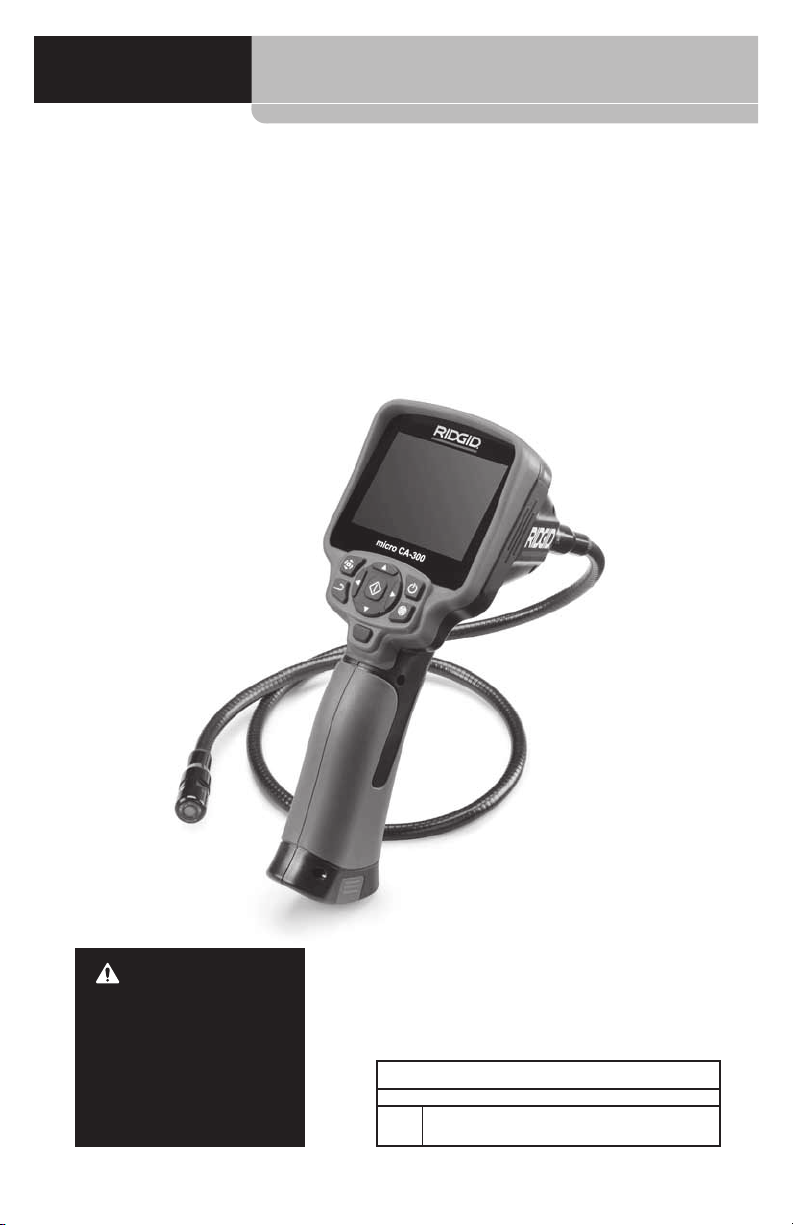
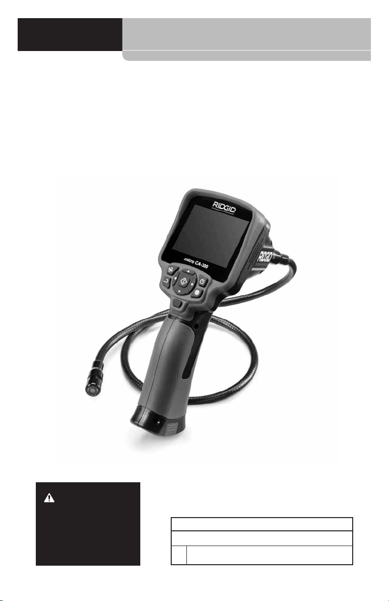
micro CA-300
micro CA-300
Inspection Camera
WARNING!
Read this Operator’s Manual carefully before using
this tool. Failure to understand and follow the contents of this manual may
result in electrical shock,
re and/or serious personal injury.
micro CA-300 Inspection Camera
Record Serial Number below and retain product serial number which is located on nameplate.
Serial
No.
Page 4

micro CA-300 Inspection Camera
Contents
Safety Symbols .................................................................................................................................................3
General Safety Information.......................................................................................................................3
Work Area Safety ...........................................................................................................................................3
Electrical Safety .............................................................................................................................................3
Personal Safety ..............................................................................................................................................3
Equipment Use and Care ...........................................................................................................................4
Service ............................................................................................................................................................... 4
Specic Safety Information ....................................................................................................................... 4
micro CA‑300 Inspection Camera Safety ............................................................................................4
Description, Specications and Standard Equipment ...............................................................5
Description ...................................................................................................................................................... 5
Specications ................................................................................................................................................. 5
Standard Equipment ................................................................................................................................... 6
Controls ............................................................................................................................................................6
FCC Statement ..................................................................................................................................................6
Electromagnetic Compatibility (EMC) ................................................................................................. 7
Icons ....................................................................................................................................................................... 7
Tool Assembly ...................................................................................................................................................7
Changing/Installing Batteries .................................................................................................................. 7
Powering with the AC Adapter .............................................................................................................. 8
Installing the Imager Head Cable or Extension Cables ................................................................ 8
Installing Accessories .................................................................................................................................. 8
Installing SD™ Card ......................................................................................................................................8
Pre-Operation Inspection .......................................................................................................................... 9
Tool and Work Area Set-Up ........................................................................................................................9
Operating Instructions ..............................................................................................................................10
Live Screen ....................................................................................................................................................11
Image Adjustment ....................................................................................................................................11
Image Capture .............................................................................................................................................12
Menu ................................................................................................................................................................12
Time Stamp ...................................................................................................................................................13
Image Quality ...............................................................................................................................................13
Video Quality ................................................................................................................................................13
Language
Date/Time .............................................................................................................................................................13
TV‑Out ..................................................................................................................................................................... 13
Storage ...................................................................................................................................................................13
Speaker ................................................................................................................................................................... 13
Auto Power O ................................................................................................................................................... 13
Factory Reset ....................................................................................................................................................... 13
About ....................................................................................................................................................................... 13
Transferring Images to a Computer ....................................................................................................13
Connecting to TV ........................................................................................................................................14
Using with SeeSnake
Maintenance ....................................................................................................................................................15
Reset Function .............................................................................................................................................15
Accessories .......................................................................................................................................................15
Storage ...............................................................................................................................................................15
Service and Repair........................................................................................................................................15
Disposal..............................................................................................................................................................15
Troubleshooting ............................................................................................................................................16
Battery Pack/Battery Charger Safety .................................................................................................16
Description and Specications ..............................................................................................................17
Charger Inspection and Set-Up .............................................................................................................18
Charging Procedure/Operating Instructions .................................................................................18
Cleaning Instructions .................................................................................................................................19
Accessories .......................................................................................................................................................19
Storage ...............................................................................................................................................................19
Service and Repair........................................................................................................................................19
Disposal..............................................................................................................................................................20
Lifetime Warranty .......................................................................................................................Back Cover
*Original Instructions ‑ English
.............................................................................................................................................................. 13
Inspection Equipment ................................................................................14
®
2
Page 5
micro CA-300 Inspection Camera
Safety Symbols
In this operator’s manual and on the product, safety symbols and signal words are used to
communicate important safety information. This section is provided to improve understand‑
ing of these signal words and symbols.
This is the safety alert symbol. It is used to alert you to potential personal injury hazards.
Obey all safety messages that follow this symbol to avoid possible injury or death.
DANGER
WARNING
CAUTION
NOTICE
DANGER indicates a hazardous situation which, if not avoided, will result in death
or serious injury.
WARNING indicates a hazardous situation which, if not avoided, could result in
death or serious injury.
CAUTION indicates a hazardous situation which, if not avoided, could result in mi‑
nor or moderate injury.
NOTICE indicates information that relates to the protection of property.
This symbol means read the operator’s manual carefully before using the equipment.
The operator’s manual contains important information on the safe and proper operation
of the equipment.
This symbol means always wear safety glasses with side shields or goggles when han‑
dling or using this equipment to reduce the risk of eye injury.
This symbol indicates the risk of hands, ngers or other body parts being caught or
wrapped in gears or other moving parts.
This symbol indicates the risk of electrical shock.
General Safety
Information
WARNING
Read all safety warnings and instructions.
Failure to follow the warnings and instruc‑
tions may result in electric shock, fire and/
or serious injury.
SAVE THESE INSTRUCTIONS!
Work Area Safety
• Keep your work area clean and well
lit. Cluttered or dark areas invite acci‑
dents.
• Do not operate equipment in explosive
atmospheres, such as in the presence
of ammable liquids, gases or dust.
Equipment can create sparks which may
ignite the dust or fumes.
• Keep children and by-standers away
while operating equipment. Distrac‑
tions can cause you to lose control.
Electrical Safety
• Avoid body contact with earthed or
grounded surfaces such as pipes, radiators, ranges and refrigerators. There
is an increased risk of electrical shock if
your body is earthed or grounded.
• Do not expose equipment to rain or
wet conditions. Water entering equip‑
ment will increase the risk of electrical
shock.
Personal Safety
• Stay alert, watch what you are doing
and use common sense when operating equipment. Do not use equipment while you are tired or under
the inuence of drugs, alcohol or
medication. A moment of inattention
while operating equipment may result
in serious personal injury.
• Do not overreach. Keep proper foot-
ing and balance at all times. This en‑
ables better control of the power tool
in unexpected situations.
3
Page 6

micro CA-300 Inspection Camera
• Use personal protective equipment.
Always wear eye protection. Protective
equipment such as dust mask, non‑
skid safety shoes, hard hat or hearing
protection used for appropriate condi‑
tions will reduce personal injuries.
Equipment Use and Care
• Do not force equipment. Use the cor-
rect equipment for your application.
The correct equipment will do the job
better and safer at the rate for which it
is designed.
• Do not use equipment if the switch
does not turn it ON and OFF. Any tool
that cannot be controlled with the
switch is dangerous and must be re‑
paired.
• Disconnect the batteries from the
equipment before making any adjustments, changing accessories, or
storing. Such preventive safety mea‑
sures reduce the risk of injury.
• Store idle equipment out of the reach
of children and do not allow persons unfamiliar with the equipment
or these instructions to operate the
equipment. Equipment can be danger‑
ous in the hands of untrained users.
• Maintain equipment. Check for miss‑
ing parts, breakage of parts and any
other condition that may aect the
equipment’s operation. If damaged,
have the equipment repaired before
use. Many accidents are caused by
poorly maintained equipment.
• Use the equipment and accessories in
accordance with these instructions,
taking into account the working conditions and the work to be performed.
Use of the equipment for operations
dierent from those intended could
result in a hazardous situation.
• Use only accessories that are recom-
mended by the manufacturer for your
equipment. Accessories that may be
suitable for one piece of equipment may
become hazardous when used with oth‑
er equipment.
• Keep handles dry and clean; free from
oil and grease. Allows for better con‑
trol of the equipment.
Service
• Have your equipment serviced by a
qualied repair person using only
identical replacement parts. This will
ensure that the safety of the tool is main‑
tained.
Specific Safety
Information
WARNING
This section contains important safety in‑
formation that is specific to the inspection
camera.
Read these precautions carefully before
using the RIDGID® micro CA‑300 In spec‑
tion Cam era to reduce the risk of electrical
shock or other serious injury.
SAVE THESE INSTRUCTIONS!
A manual holder is supplied in the carrying
case of the micro CA‑300 Inspection Camera
to keep this manual with the tool for use by
the operator.
micro CA‑300 Inspection Camera
Safety
• Do not expose the display unit to
water or rain. This increases the risk
of electrical shock. The micro CA‑300
imager head and ca ble are waterproof
to 10’ (3 m). The hand‑held display unit
is not.
• DonotplacethemicroCA‑300inspec‑
tion Cam era anywhere that may contain a live electrical charge. This in‑
creases the risk of electrical shock.
• DonotplacethemicroCA‑300inspec‑
tion Cam era anywhere that may contain moving parts. This increases the
risk of entanglement injuries.
• Donotusethisdeviceforpersonal
inspection or medical use in any
way. This is not a medical device. This
could cause personal injury.
• Always use appropriate personal
protective equipment while handling and using the micro CA-300
inspection Cam er a. Drains and other
areas may contain chemicals, bacte‑
ria and other substances that may be
toxic, infectious, cause burns or other
issues. Appropriate personal pro-
tective equipment always includes
4
Page 7

micro CA-300 Inspection Camera
safety glasses and gloves, and may
include equipment such as latex or
rubber gloves, face shields, goggles,
protective clothing, respirators and
steel‑toed foot wear.
• Practicegoodhygiene. Use hot, soapy
wa ter to wash hands and other body
parts exposed to drain contents after
handling or using the micro CA‑300 In‑
spec tion Camera to inspect drains and
other areas that may contain chemi‑
cals or bacteria. Do not eat or smoke
while operating or handling the micro
CA‑300 Inspection Camera. This will
help prevent contamination with toxic
or infectious material.
• Do not operate the micro CA-300 In-
spection Camera if operator or device
is standing in water. Operating an elec‑
trical device while in water increases
the risk of electrical shock.
The EC Declaration of conformity (890‑011‑
320.10) will accompany this manual as a
separate booklet when required.
If you have any question concerning this
RIDGID® product:
– Contact your local RIDGID distributor.
– Visit www.RIDGID.com or www.RIDGID.eu
to nd your local RIDGID contact point.
– Contact RIDGID Technical Services De‑
part ment at rtctechservices@emer son.
com, or in the U.S. and Canada call (800)
519‑3456.
Description, Specifications
and Standard Equipment
Description
The RIDGID micro CA‑300 Inspection Cam era
is a powerful handheld digital recording de‑
vice. It is a complete digital platform that al‑
lows you to perform inspections and record
pictures and videos in hard to reach areas.
Several image manipulation features such
as image rotation and digital zoom are built
into the system to ensure detailed and accu‑
rate visual inspections. The tool has external
memory and TV‑Out features. Accessories
(hook, magnet and mirror) are included to
attach to the imager head to provide appli‑
cation exibility.
Specifications
Recommended Use Indoor
Viewable Distance... 0.4" (10 mm) to ∞
Display.......................... 3.5" (90 mm) Color TFT
Camera Head.............
Lighting........................ 4 Adjustable LEDs
Cable Reach................ 3' (90 cm), Expand‑
Photo Format............. JPEG
Image Resolution..... Good [640 x 480],
Video Format............. AVI
Video Resolution...... Good [320 x 240],
Frame Rate.................. up to 30 FPS
TV‑Out......................... PAL/NTSC
Built‑In Memory...... 235 MB Memory
External Memory.... SD™ Card 32 GB max
Data Output.............. USB Data Cable and
Operating
Temperature............. 32°F to 113°F
Storage
Temperature............. ‑4°F to 140°F
Power Supply............ 3.7V Li‑Ion Battery AC
Weight......................... 5.5 lbs (2,5 kg)
(320 x 240 Resolution)
3
/4" (17 mm)
able to 30' (9 m) with
Op tional Exten sions,
Imager and Cable
are Water proof to 10'
(3 m), IP67
Better [1024 x 768],
Best [1600 x 1200]
Best [640 x 480]
User selectable
(4 GB supplied)
SD™ Card
(0°C to 45°C)
(‑20°C to 60°C)
Adapter 5V, 1.5 Amp
5
Page 8
micro CA-300 Inspection Camera
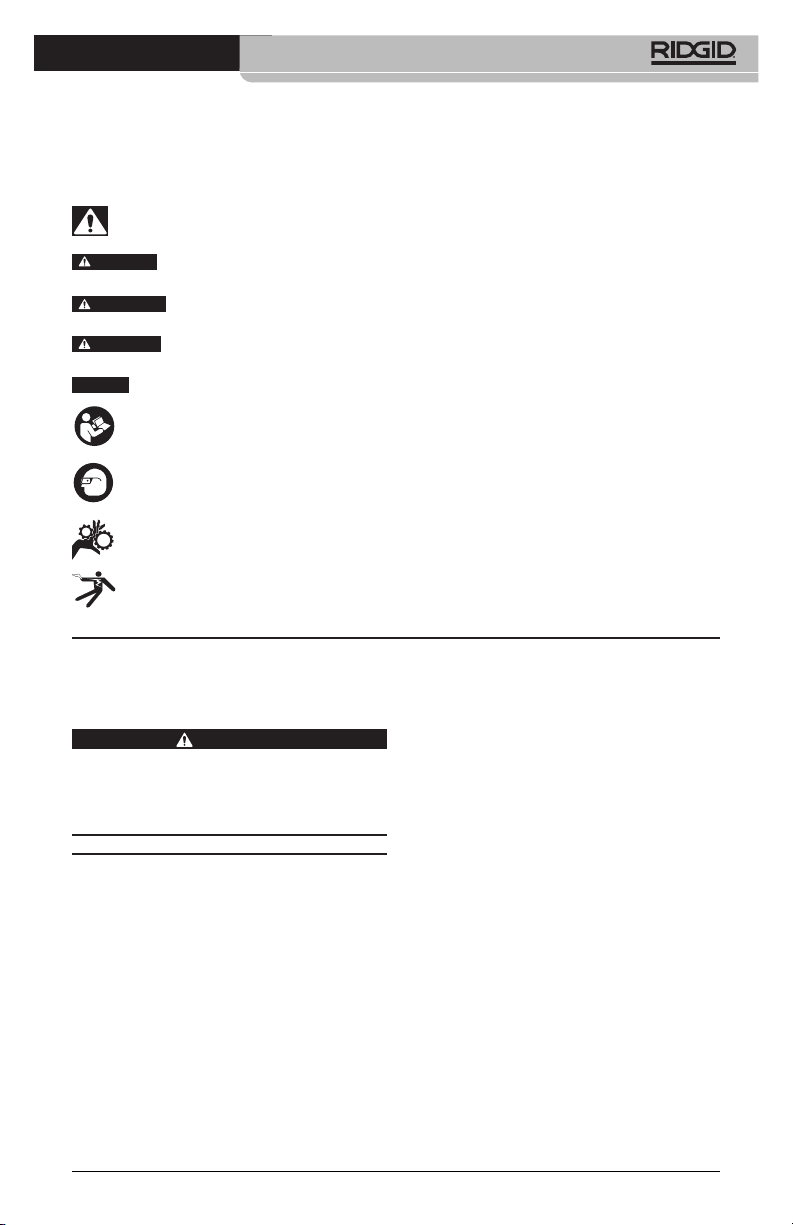
Standard Equipment
The micro CA‑300 Inspection Camera comes
with the following items:
• microCA‑300Handset
• 17mmImager
• 3’(90cm)USBCable
• 3’(90cm)RCACablewithAudio
• Hook,Magnet,MirrorAttachments
• 3.7VLi‑IonBattery
• Li‑IonBatteryChargerwithCord
• ACAdapter
• HeadsetAccessorywithMicrophone
• 4GBSD™Card
• Operator’sManualPack
Figure 1 - micro CA-300 Inspection Camera
Integrated Microphone
AC Adapter
Headset
Jack
Speaker
Figure 3 - Right Side Port Cover
Reset
Button
Figure 4 -Left Side Port Cover
TV-O ut
Mini-B USB
SD™ Slot
Controls
Rotate
Image
Return
Arrows
Shutter
Figure 2 - Controls
6
Power
Menu
Select/Confirm
FCC Statement
This equipment has been tested and found
to comply with the limits for a Class B digital
device, pursuant to part 15 of the FCC Rules.
These limits are designed to provide reason‑
able protection against harmful interference
in a residential installation.
This equipment generates, uses, and can
radiate radio frequency energy and, if not
installed and used in accordance with the
instructions, may cause harmful interference
to radio communications.
However, there is no guarantee that interfer‑
ence will not occur in a particular installa‑
tion.
If this equipment does cause harmful in‑
terference to radio or television reception,
which can be determined by turning the
equipment OFF and ON, the user is encour‑
aged to try to correct the interference by one
or more of the following measures:
Page 9
micro CA-300 Inspection Camera
• Reorientorrelocatethereceivingantenna.
• Increasetheseparationbetweenthequip‑
ment and receiver.
• Consultthedealeroranexperiencedradio/
TV technician for help.
Electromagnetic
Compatibility (EMC)
The term electromagnetic compatibility is
taken to mean the capability of the prod‑
uct to function smoothly in an environment
where electromagnetic radiation and elec‑
trostatic discharges are present and without
causing electromagnet interference to other
equipment.
NOTICE
ion Camera conforms to all applicable EMC
standards. However, the possibility of it caus‑
ing interference in other devices cannot be
precluded.
The RIDGID micro CA‑300 Inspect‑
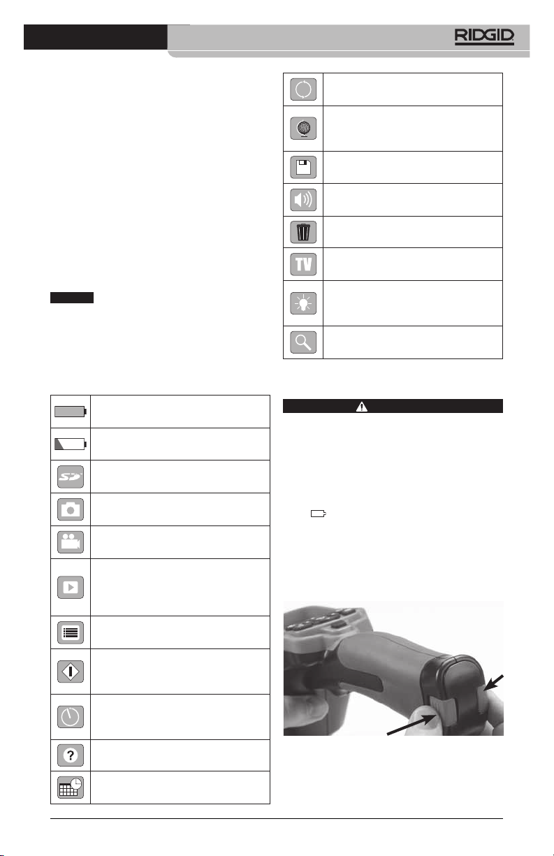
Icons
Battery Life Indicator – Fully
charged battery.
Battery Life Indicator – Less than
25% of battery charge remains.
SD™ Card – Indicates an SD card
has been inserted into the device.
Still Camera – Indicates device is
operating in still camera mode.
Video Camera – Indicates device is
operating in video camera mode.
Playback Mode – Pressing select
on this icon allows you to view and
delete previously saved images and
video.
Menu – Push select on this icon to
be taken to the menu screen.
Select – Pressing select from the
live screen will take you to the
primary settings screen.
Automatic Power O – Device will
automatically shut down after 5, 15
or 60 minutes of inactivity.
About – Displays software version.
Factory Reset – Restore factory
defaults.
Language – Choose between,
English, French, Spanish, German,
Dutch, Italian, etc.
Save – Indicates image or video
has been saved to memory.
Speaker – Keep the speaker on or
o during video playback.
Trash – Delete conrmation icon.
TV – Chose between NTSC and PAL
to enable TV out video format.
LED Brightness – Press right & left
arrows to change the LED bright‑
ness.
Zoom – Press up & down arrows to
change the zoom from 1.0x to 3.5x
Tool Assembly
To reduce the risk of serious injury during
use, follow these procedures for proper as‑
sembly.
Changing/Installing Batteries
The micro CA‑300 is supplied without the
battery installed. If the battery indicator dis‑
plays
Re move the battery prior to long term stor‑
age to avoid battery leakage.
1. Squeeze the battery clips (See Figure 5)
and pull to remove battery compart‑
ment cover. If needed, slide battery out.
Figure 5 - Battery Compartment Cover
WARNING
, the battery needs to be recharged.
Time and Date – Enter this screen
to set time and date.
7
Page 10
micro CA-300 Inspection Camera
they are aligned, nger tighten the knurled
knob to hold the connection in place.
Figure 8 - Cable Connections
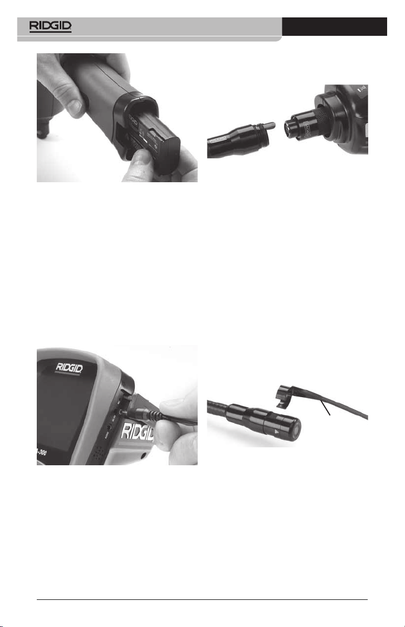
Figure 6 - Removing/Installing Battery
2. Insert contact end of battery into the in‑
spection tool, as shown in Figure 6.
3. Replace battery compartment cover.
Powering with the AC Adapter
The micro CA‑300 Inspection Camera can al‑
so be powered using the supplied AC Adapt‑
er.
1. Open the right side port cover (Figure 3).
2. With dry hands, plug the AC adapter into
the outlet.
3. Insert the AC adapter barrel plug into the
port marked “DC 5V”.
Figure 7 - Powering the Unit with AC
Adapter
Installing the Imager Head Cable
or Extension Cables
To use the micro CA‑300 Inspection Cam er a,
the imager head cable must be connected to
the handheld display unit. To connect the ca‑
ble to the handheld display unit, make sure
the camera socket key and display unit sock‑
et slot (Figure 8) are properly aligned. Once
3’ (90 cm) and 6’ (180 cm) cable extensions
are available to increase the length of your
camera cable up to 30 feet (9 meters). To in‑
stall an extension, rst remove the camera
head cable from the display unit by loosen‑
ing the knurled knob. Connect the extension
to the handheld as described above (Figure
8). Connect the keyed end of the camera
head cable to the slotted end of the exten‑
sion and nger tighten the knurled knob to
hold the connection in place.
Installing Accessories
The three included accessories, (Hook, Mag‑
net, Mirror) all attach to the imager head the
same way.
To connect, hold the imager head as shown in
Figure 9. Slip the semicircle end of the acces‑
sory over the ats of the imager head. Then
rotate the accessory a 1/4 turn to retain.
Accessory
Figure 9 - Installing an Accessory
Installing SD™ Card
Open the left side port cover (Figure 4) to ac‑
cess the SD card slot. Insert the SD card into
the slot making sure the contacts are facing
towards you and the angled portion of the
card is facing down (Figure 10) . SD cards can
only be installed one way – do not force.
When an SD card is installed, a small SD card
icon will appear in the bottom right hand
portion of the screen, along with the num‑
ber of images or length of video that can be
stored on the SD card.
8
Page 11
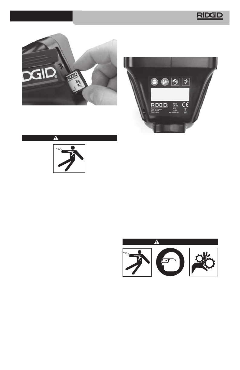
Figure 10 - Inserting the SD Card
Pre‑Operation Inspection
WARNING
Before each use, inspect your Inspec tion
Camera and correct any problems to reduce
the risk of serious injury from electric shock
and other causes and prevent tool damage.
1. Make sure the unit is OFF.
2. Remove the battery and inspect it for
signs of dam age. Re place battery if nec‑
essary. Do not use Inspection Camera if
the battery is damaged.
3. Clean any oil, grease or dirt from the e quip ‑
ment. This aids inspection and helps prevent
the tool from slipping from your grip.
4. Inspect micro CA‑300 Inspection Camera
for any broken, worn, miss ing or binding
parts or any condition which may pre‑
vent safe and normal operation.
5. Inspect the camera head lens for con‑
densation. To avoid damaging the unit,
do not use the camera if condensation
forms inside the lens. Let the water evap‑
orate before using.
6. Inspect the full length of the cable for
cracks or damage. A damaged cable
could allow water to enter the unit and
increase the risk of electrical shock.
7. Check to make sure the connections be‑
tween the handheld unit, extension ca‑
bles and imager cable are tight. All con‑
nections must be properly assembled for
micro CA-300 Inspection Camera
the cable to be water resistant. Con rm
unit is properly assembled.
8. Check that the warning label is present,
rmly attached and readable (Figure 11).
Figure 11 - Warning Label
9. If any issues are found during the inspec‑
tion, do not use the inspection camera
until it has been properly serviced.
10. With dry hands, re‑install the battery.
11. Press and hold the Power Button for one
second. The imager lights should come
on, then a splash screen will appear.
Once the camera is ready, a live image of
what the camera sees is displayed on the
screen. Con sult the Troubleshooting sec‑
tion of this manual if no picture appears.
12. Press and hold the Power Button for one
second to turn camera OFF.
Tool and Work Area Set‑Up
WARNING
Set up the micro CA‑300 In spec tion Cam‑
era and work area according to these pro‑
cedures to reduce the risk of injury from
electrical shock, entanglement and other
causes and prevent tool damage.
1. Check work area for:
• Adequatelighting.
•Flammable liquids,vapors or dust that
may ignite. If present, do not work in area
until sources have been identied and
corrected. The micro CA‑300 In spection
9
Page 12
micro CA-300 Inspection Camera
Camera is not explosion proof and can
cause sparks.
•Clear,level,stable,dryplaceforoperator.
Do not use the inspection camera while
standing in water.
2. Examine the area or space that you will
be inspecting and determine if the micro
CA‑300 Inspection Camera is the correct
piece of equipment for the job.
• Determinetheaccesspointstothespace.
The minimum opening the cam era head
can t through is approximate ly
3
/4”
(19 mm) in diameter for the 17 mm cam‑
era head.
• Determinethedistancetotheareatobe
inspected. Extensions can be add ed to
the camera to reach up to 30’ (9 m).
• Determineifthereareanyobstaclesthat
would require very tight turns in the
cable. The inspection camera ca ble can
go down to a 5” (13 cm) radius without
damage.
• Determineifthereisanyelectricalpower
supplied to the area to be inspected. If
so, the power to the area must be turned
OFF to reduce the risk of electric shock.
Use appropriate lock out procedures to
prevent the power from being turned
back on during the inspection.
• Determineifanyliquidswillbeencoun‑
tered during the inspection. The cable
and imager head are waterproof to a
depth of 10’ (3 m). Greater depths may
cause leakage into the cable and imager
and cause electric shock or damage the
equipment. The handheld display unit is
water resistant (IP65) but should not be
submerged in water.
• Determine if anychemicalsarepresent,
especially in the case of drains. It is im‑
portant to understand the specic safety
measures required to work a round any
chemicals present. Contact the chemical
manufacturer for required information.
Chemicals may damage or degrade the
inspection camera.
• Determine the temperature of the area
and items in the area. The working tem‑
perature of the inspection camera is be‑
tween 32°F to 130°F (0°C to 55°C). Use
in areas outside of this range or contact
with hotter or colder items could cause
camera damage.
• Determineifanymovingpartsarepres‑
ent in the area to be inspected. If so,
these parts must be deactivated to pre‑
vent movement during inspection to
reduce the risk of entanglement. Use
appropriate lock out procedures to pre‑
vent the parts from moving during the
inspection.
If the micro CA‑300 Inspection Camera is
not the correct piece of equipment for the
job, other inspection equipment is available
from RIDGID. For a complete listing of RIDGID
products, see the RIDGID catalog, online at
www.RIDGID.com or www.RIDGID.eu.
3. Make sure the micro CA‑300 Inspec tion
Camera has been properly inspect ed be‑
fore each use.
4. Install the correct accessories for the ap‑
plication.
Operating Instructions
WARNING
Always wear eye protection to protect your
eyes against dirt and other foreign objects.
Follow operating instructions to reduce the
risk of injury from electrical shock, entan‑
glement and other causes.
1. Make sure that the Inspection Camera
and work area have been properly set up
and that the work area is free of bystand‑
ers and other distractions.
2. Press the Power Button for one second.
The imager lights should come ON, then
a splash screen will appear. This screen
tells you the device is booting up. Once
the product is fully powered up, the
screen will automatically switch to the
live screen.
10
Page 13

Figure 12 - Splash Screen
Live Screen
The live screen is where you will do most of
your work. A live image of what the cam‑
era sees is displayed on the screen. You can
zoom, adjust LED brightness and take im‑
ages or video from this screen.
The screen has a status bar at the top show‑
ing the tool mode, battery status, and an
SD™ card icon if inserted, and the bottom in‑
formation bar shows information about the
Time and Date.
Status Bar
Information Bar
Figure 13 - Live Screen
When the Inspection Camera is turned ON,
the default mode is for capturing still im‑
ages.
Pressing the menu button at any time will ac‑
cess the menu. The menu will overlay on the
LIVE Screen. Use the right and left arrow
buttons to switch to the MODE category. Use
the up and down arrows
tween menu items and press select
desired.
to navigate be‑
as
micro CA-300 Inspection Camera
Figure 14 - Screen Shot of Mode Selection
3. If the other inspection camera settings
(such as time stamp, image quality, lan‑
guage, Date/Time, TV out, and Storage
device) need to be adjusted, see Menu
Section.
4. Prepare the camera for inspection. The
camera cable may need to be pre‑formed
or bent to properly inspect the area. Do
not try to form bends less than 5” (13 cm)
radius. This can damage cable. If inspect‑
ing a dark space, turn the LEDs on before
inserting the camera or cable.
Do not use excessive force to insert or
withdraw the cable. This may result in
damage to the inspection camera or
inspection area. Do not use the cable
or imager head to modify surroundings,
clear pathways or clogged areas, or as
anything other than an inspection de‑
vice. This may result in damage to the
inspection camera or inspection area.
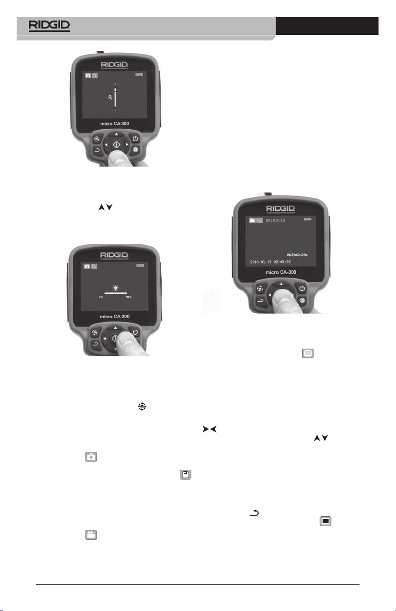
Image Adjustment
Adjust LED Brightness: Pressing the right
and left arrow button
(In live screen) will increase or decrease the
LED brightness. A brightness indicator bar
will be displayed on the screen as you adjust
brightness.
on the button pad
11
Page 14
micro CA-300 Inspection Camera
Figure 15 - Adjusting LED
Zoom: The micro CA‑300 Inspection Camer a
has a 3.5x digital zoom. Simply press the up
and down arrows
to zoom in or out. A zoom indicator bar will
be displayed on the screen as you adjust
your zoom.
while in the live screen
cording duration will show at the top of the
screen. Press the shutter button again to stop
the video. It may take several seconds to save
the video if saving to the internal memory.
The micro CA‑300 features an integrated micro‑
phone and speaker for recording and playback
of audio with video. A headset with integrated
microphone is included and may be used instead
of the integrated speaker and microphone. Plug
the headset into the audio port on the right side
of the camera.
5. When the inspection is complete, care‑
fully withdraw the camera and cable
from the inspection area.
Figure 16 - Adjusting Zoom
Image Rotation: If needed, the image/video
seen on the screen can be rotated in 90 de‑
gree increments counter clockwise by press‑
ing the rotate image button
.
Image Capture
Capturing a Still Image
While in the live screen, make sure the still
camera icon
portion of the screen. Press the shutter but‑
ton to capture the image. The save icon
will momentarily appear on the screen. This
indicates the still image has been saved to
the internal memory or SD™ card.
Capturing a Video
While in the live screen, make sure the video
camera icon
portion of the screen. Press the shutter but‑
ton to start capturing video. When the device
is recording a video, a red outline will ash
around the video mode icon and the re‑
12
is present at the top left
is present at the top left
Figure 17 - Video Recording Screen
Menu
Pressing the menu button at any time
will access the menu. The menu will overlay
on the LIVE Screen. From the menu, the user
will be able to change to the various modes
or enter the settings menu.
There are dierent setting categories to
choose from (Figure 18) while in the settings
screen. Use the right and left arrow buttons
to switch from one category to the next.
Use the up and down arrows
gate the menu items. The selected category
will be highlighted with a bright red outline.
Once the desired setting is reached, press
select to change to the new selection. The
changes are automatically saved when they
are changed.
While in menu mode, you can press the re‑
turn button
screen or hit the menu button
the menu and return to the live screen.
to return to the previous
to navi‑
to exit
Page 15
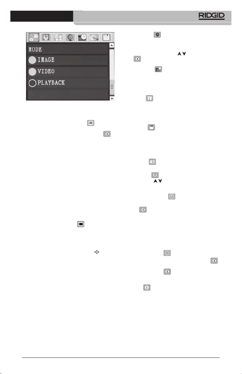
Figure 18 - Settings Screen
Playback Mode
1. Press the Menu button
down arrow to select Playback mode
icon and use the Select button
enter play‑back mode. Select either Im‑
age or Video to playback the desired le.
The playback mode is the interface into
saved les. It will default to the last le
recorded.
2. While reviewing the image the user will
be able to cycle through all saved im‑
ages, delete an image and display le
informa tion.
3. While reviewing a video, a user will be
able to navigate through videos, pause,
seek forward, restart, add bookmark and
delete.
Deleting Files
Press menu button
back mode to delete the image or video.
The delete conrmation dialog allows
the user to delete unwanted les. The ac‑
tive icon is outlined in red. Navigation is
done with the arrow buttons
, use the
to
while in play‑
.
Time Stamp
Enable or Disable the display of the Date and
Time.
Image Quality
Select the desired image quality. The higher
the image quality, the more space that will
be used for each le. The approximate re‑
maining number of images that can be saved
will be shown.
Video Quality
Select the desired image quality. The higher
the video quality the more space that will be
used for each le. The approximate remaining
time that can be recorded will be shown.
micro CA-300 Inspection Camera
Language
Select the “Language” icon in the menu and
press Select. Select dierent languages with
up/down arrow buttons
to save the language setting.
lect
, then press Se‑
Date/Time
Select Set Date or Set Time to set the current
date or time. Select Format Date or Time to
change how the date/time is displayed.
TV‑Out
Select the “NTSC” or “PAL” to enable the TV‑
Out for the video format required. Select OFF
to Disable the TV‑Out.
Storage
Select the storage icon in the menu and
press select to format the SD™ memory card.
This feature is normally only needed if there
is an issue with the SD™ card.
Speaker
Select the speaker icon in the menu and
press select
down button
OFF during video playback.
. Select ON or OFF with up/
to keep the speaker ON or
Auto Power Off
Select the auto‑power o icon and press
select
auto ma tic shut down function. Select the 5
Minutes, 15 Minutes or 60 Minutes to turn
OFF the tool upon 5/15/60 minutes of non‑
operation. Automatic shut down setting will
not be activated when recording or playing
video.
. Select disable to turn OFF the
Factory Reset
Select the reset icon and press select .
Conrm the reset function by selecting Yes
and press Select
the tool to the factory set up.
again. This will reset
About
Select the about function to display the rm‑
ware revision of the micro CA‑300 as well as
the software copyright information.
Transferring Images to a
Computer
Connect the micro CA‑300 to a computer us‑
ing the USB cable. The USB connected screen
is displayed on the micro CA‑300 screen and
the camera is accessible as a standard USB
storage device.
13
Page 16
micro CA-300 Inspection Camera
The copy and delete options are available
from computer operation.
Connecting to TV
The micro CA‑300 Inspection Camera can be
connected to a television or other monitor
for remote viewing or recording through the
included RCA cable.
Open the right side port cover (Figure 3). In‑
sert the RCA cable into the TV‑Out jack. Insert
the other end of the cable into the Video‑In
jack on the television or monitor. Check to
make sure the video format (NTSC or PAL)
output is set properly. The television or
monitor may need to be set to the proper
input to allow viewing.
Using with SeeSnake® Inspection
Equipment
The micro CA‑300 Inspection Camera can
also be used with various SeeSnake Inspec‑
tion Equipment and is specically designed
to be used with the microReel, microDrain™
and the nanoReel Inspection Systems. When
used with these types of equipment, it retains
all of the functionality described in this man‑
ual. The micro CA‑300 Inspection Camera can
also be used with other SeeSnake Inspection
Equipment for viewing and recording only.
For use with SeeSnake Inspection Equip‑
ment, the imager head and any cable exten‑
sions must be removed. For the microReel,
microDrain, nanoReel and similar equip‑
ment, see the operator’s manual for informa‑
tion on proper connection and use. For other
SeeSnake Inspection Equipment (typically a
reel and monitor), an adapter must be used
to connect the micro CA‑300 Inspection
Camer a to a Video‑Out port on the SeeSnake
Inspec tion Equipment. When connected in
this manner, the micro CA‑300 Inspection
Camera will display the camera view and can
be used for recording.
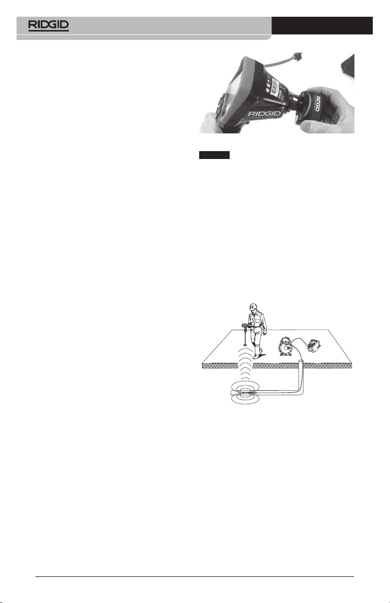
When connecting to SeeSnake Inspection Equip‑
ment (microReel, microDrain™, or nano ‑Reel),
align the interconnect module connected to your
reel with the cable connector onthe micro CA‑300
Inspection Camera, and slide it straight in, seating
it squarely. (See Figure 19.)
Figure 19 - Camera Connector Plug Installed
NOTICE
prevent damage.
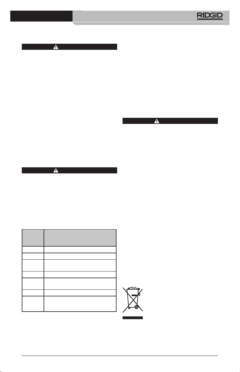
Locating the Sonde
If used with a sonde (In‑Line Transmitter),
the sonde can be controlled two ways. If the
reel is equipped with a sonde key, that can
be used to turn the sonde ON and OFF. Oth‑
erwise, the sonde is turned ON by decreas‑
ing LED brightness to zero. Once the Sonde
has been located, the LEDs can be returned
to their normal brightness level to continue
the inspection.
A RIDGID locator such as the SR‑20, SR‑60,
Scout, or NaviTrack® II set to 512 Hz can be
used to locate features in the drain being in‑
spected.
Figure 20 - Locating the Reel Sonde
To locate the Sonde, turn the locator ON and
set it to Sonde mode. Scan in the direction of
the Sonde’s probable location until the loca‑
tor detects the Sonde. Once you have detect‑
ed the Sonde, use the locator indications to
zero in on its location precisely. For detailed
instructions on Sonde locating, consult the
Oper ator’s Manual for the locator model you
are using.
Do not twist the connector plug to
14
Page 17
micro CA-300 Inspection Camera
Maintenance
WARNING
Remove batteries before cleaning.
• Alwayscleantheimagerheadandcable
after use with mild soap or mild deter‑
gent.
• Gently clean the display screen with a
clean dry cloth. Avoid rubbing too hard.
• Use only alcohol swabs to clean the
cable connections.
• Wipethehandhelddisplayunitdown
with a clean, dry cloth.
Reset Function
If the unit stops functioning and does not
operate, press the Reset Button (under the
left side port cover – Figure 4). The unit may re‑
cover to normal operation when re started.
Accessories
WARNING
To reduce the risk of serious injury, only use
accessories specifically designed and rec‑
ommended for use with the RIDGID micro
CA‑300 Inspection Camera such as those
listed below. Other Ac ces sories suitable
for use with other tools may be hazardous
when used with the micro CA‑300 Inspec‑
tion Camera.
micro CA-300 Inspection Camera
Accessories
Catalog
No. Description
37108 3’ (90 cm) Cable Extension
37113 6' (180 cm) Cable Extension
37103 Imager Head and 90 cm Cable ‑
17 mm
37098 1m length 6 mm diameter imager
37123 17 mm Accessory Pack (Hook,
Magnet, Mirror)
40028 AC Adapter
40623 Headset Accessory with
Microphone
Further information on accessories speci c to
this tool can be found in the RIDGID Catalog and
online at www.RIDGID.com or www.RIDGID.eu.
Storage
The RIDGID micro CA‑300 Inspection Cam era
must be stored in a dry secure area between
‑4°F (‑20°C) and 158°F (70°C) and humidity
between 15% and 85% RH.
Store the tool in a locked area, out of the
reach of children and people unfamiliar with
the micro CA‑300 Inspection Cam era.
Remove the battery before any long period
of storage or shipping to avoid battery leak‑
age.
Service and Repair
WARNING
Improper service or repair can make the
RIDGID micro CA‑300 Inspection Camera
unsafe to operate.
Service and repair of the micro CA‑300 In spec‑
tion Camera must be performed by a RIDGID
In dependent Authorized Service Center.
For information on your nearest RIDGID In‑
depen dent Service Center or any service or
repair questions:
• ContactyourlocalRIDGIDdistributor.
• Visitwww.RIDGID.comorwww.RIDGID.eu
to nd your local RIDGID contact point.
• ContactRIDGIDTechnicalServicesDe‑
partment at rtctechservices@emerson.
com, or in the U.S. and Canada call (800)
519‑3456.
Disposal
Parts of the RIDGID micro CA‑300 Inspection
Camera contain valuable materials and can
be recycled. There are companies that spe‑
cialize in recycling that may be found locally.
Dispose of the com ponents in compliance
with all applicable regulations. Contact your
local waste management authority for more
information.
For EC Countries: Do not dispose of
elec trical equipment with house‑
hold waste!
According to the European Guide‑
line 2002/ 96/EC for Waste Elec‑
trical and Electronic Equipment
and its imple men tation into na‑
tional legislation, electrical equipment that
is no longer usable must be collected sepa‑
rately and disposed of in an environmentally
correct manner.
15
Page 18
micro CA-300 Inspection Camera
Troubleshooting
SYMPTOM POSSIBLE REASON SOLUTION
Display turns ON, but
does not show image.
LEDs on imager head
are dim at max brightness, display switches
between black and
white, color display
turns itself OFF after a
brief period.
Unit will not turn ON. Dead battery. Replace with charged battery.
Loose cable connections. Check cable connections, clean if re‑
Imager is broken. Replace the Imager.
Imager head covered by debris. Visually inspect imager head to make
Battery low on power. Replace battery with charged bat‑
Unit need to be reset. Reset unit. See “Maintenance” Sec-
quired. Re‑attach.
certain it is not covered by debris.
tery.
tion.
Battery Pack/Battery
Charger Safety
WARNING
To reduce the risk of serious injury, read
these precautions carefully before using
the battery charger or battery
Battery Charger Safety
• Charge only the RIDGID rechargeable
battery listed in the Accessories Section with the RIDGID Battery Charger. Other types of batteries may burst
causing personal injury and property
damage.
• Do not probe battery charger with
conductive objects. Shorting of bat‑
tery terminals may cause sparks, burns
or electrical shock.
• Do not insert battery into charger if
charger has been dropped or damaged in any way. A damaged charger
increases the risk of electrical shock.
• Charge battery in temperatures above
32°F (0°C) and below 122°F (50°C).
Store charger in temperatures above ‑4°F
(‑20°C) and below 104°F (40°C). Storage
for a long time at temperatures above
104°F (40°C) can reduce the capacity of
the battery. Proper care will prevent se‑
rious damage to the battery. Improper
16
care of the battery may result in battery
leakage, electrical shock and burns.
• Use an appropriate power source.
Do not attempt to use a step‑up trans‑
former or an engine generator, doing
so may cause damage to the charger
resulting in electrical shock, re or
burns.
• Do not allow anything to cover the
charg er while in use. Proper ventilation
is required for correct operation of the
charger. Allow a minimum of 4” (10 cm) of
clearance around the charger for proper
ventilation.
• Unplug the charger when not in use.
This reduces the risk of injury to chil‑
dren and untrained persons.
• Unplug the charger from outlet be-
fore attempting any maintenance or
cleaning. Reduces the risk of electrical
shock.
• Do not charge battery in damp, wet
or explosive environment. Do not
expose to rain, snow or dirt. Contami‑
nants and moisture increase the risk of
electrical shock.
• Do not open the charger housing.
Have repairs performed only at autho‑
rized locations.
Page 19
micro CA-300 Inspection Camera
• Do not carry charger by power cord.
Reduces the risk of electrical shock.
• The RIDGID Battery Charger is not
intended for use by persons (includ‑
ing children) with reduced physical,
sensory or mental capabilities, or lack
of experience and knowledge, un‑
less they have been given supervision
or instruction concerning use of the
RIDGID Battery Charger by a person
responsible for their safety.
• Keep children and by-standers away
while operating equipment. Distrac‑
tions can cause you to lose control.
• Have your equipment (including
power supply cord) serviced by a
qualied repair person using only
identical replacement parts. If the
equipment is damaged, it must be
replaced by the manufacturer, its
service agent or similarly qualied
persons in order to avoid a hazard.
This will ensure that the safety of the
tool is maintained.
Battery Safety
• Properly dispose of the battery. Ex po‑
sure to high temperatures can cause the
battery to explode, so do not dispose of
in a re. Place tape over the terminals
to prevent direct contact with other ob‑
jects. Some countries have regulations
concerning battery disposal. Please fol‑
low all applicable regulations.
• Do not insert the battery with cracked
case into charger. Damaged batteries
increase the risk of electrical shock.
• Never disassemble battery. There are
no user‑serviceable parts inside the
battery. Disassembling batteries may
cause electrical shock or personal in‑
jury.
• Avoid contact with uids oozing from
defective battery. Fluids may cause
burns or skin irritation. Thoroughly rinse
with water in case of accidental contact
with uid. Consult doctor if uid comes
into contact with eyes.
Description and
Specifications
Description
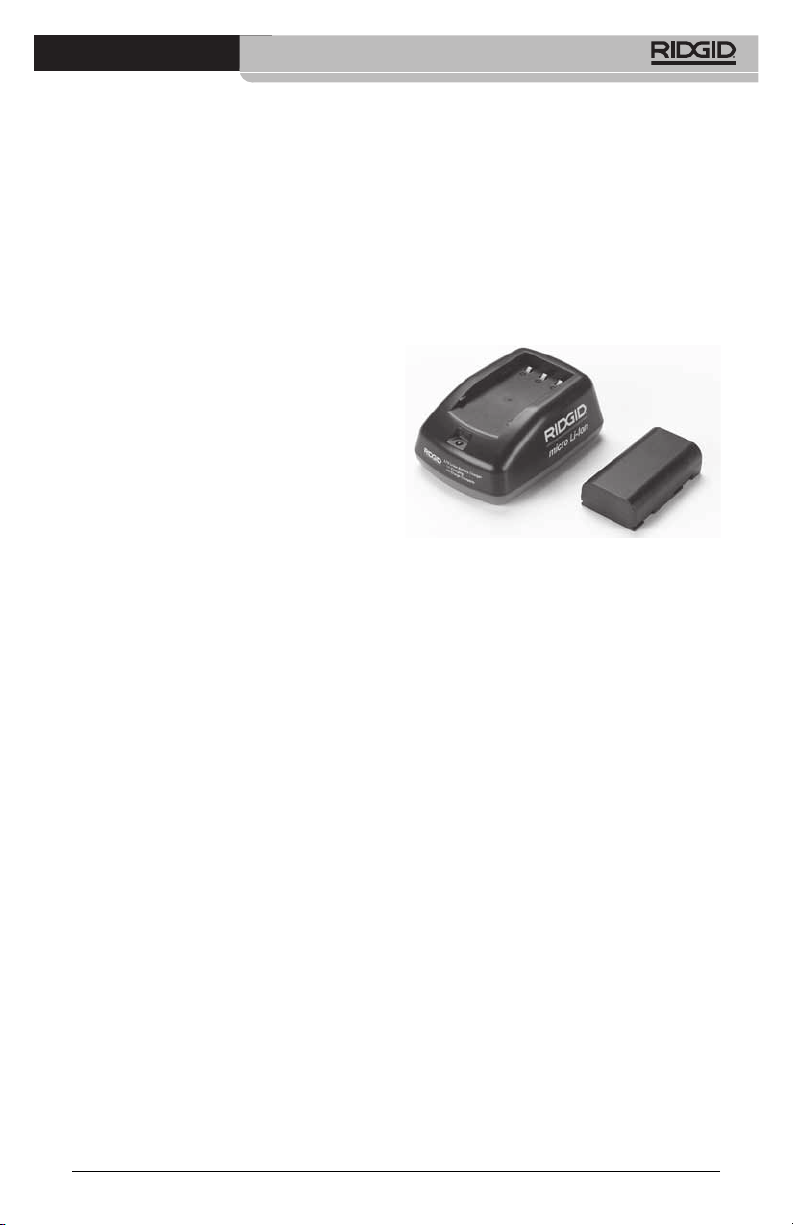
The RIDGID Battery Charger (Catalog Num‑
ber 37088), when used with appropriate bat‑
teries (Catalog Number 37083) listed in the
Accessories section, is designed to charge a
3.7V Li‑Ion RIDGID battery in approximately
4 ‑ 5 hours. This charger requires no adjust‑
ments.
Figure 21 - Battery and Charger
Specifications
Input.............................. 100 ‑ 240 VAC, 50 / 60 Hz
Output.......................... 4.2V DC
Battery Type................ 3.7V Li‑Ion
Battery Capacity........ 4.2Ah
Input Current ............ 0.3A (AC) / 1A (DC)
Weight.......................... 0.4 lbs (0,02kg)
Charging Time........... 4 to 5 Hrs
Cooling......................... Passive Convection
Cooling (No Fan)
17
Page 20
micro CA-300 Inspection Camera
Charger Inspection and
Set‑Up
WARNING
Before use, inspect the charger and batter‑
ies and correct any problems. Set up char‑
ger according to these procedures to reduce
the risk of injury from electrical shock, fire,
and other causes and prevent tool and sys‑
tem damage. Always wear eye protection
to protect your eyes against dirt and other
foreign objects.
1. Make sure the charger is unplugged. In‑
spect the power cord, charger and bat‑
tery for damage or modications, or bro‑
ken, worn, missing, misaligned or binding
parts. If any problems are found, do not
use charger until the parts have been re‑
paired or replaced.
2. Clean any oil, grease or dirt from the equip‑
ment as described in the Cleaning Instruc‑
tions section, especially handles and con‑
trols. This helps prevent the equipment from
slipping from your grip and allows proper
ventilation.
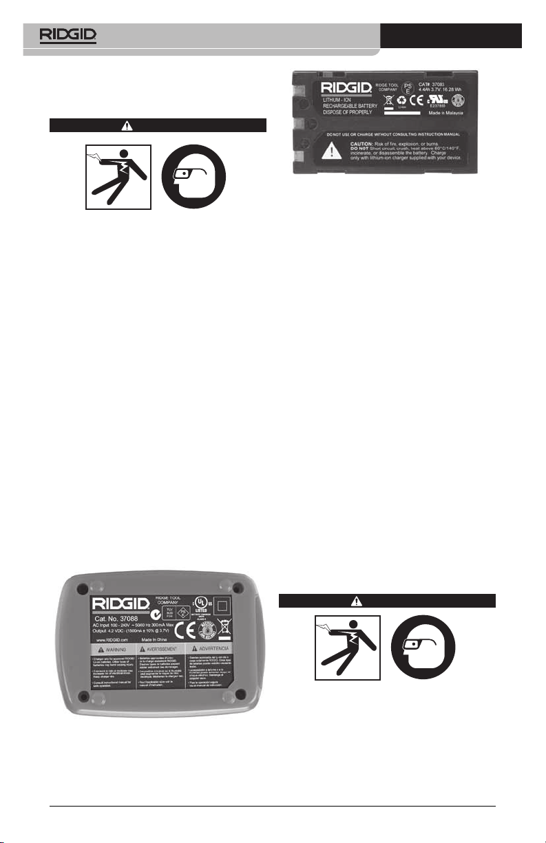
3. Check to see that all warning labels and
decals on the charger and battery are in‑
tact and readable. (See Figures 22 & 23.)
Figure 23 - Label on Battery
4. Select an appropriate location for the char‑
ger before use. Check work area for:
• Adequatelighting.
• Clear,level,stable,dryplaceforcharger.
Do not use the device in wet or damp
areas.
• Proper operating temperature range.
The charger and battery must both be
between 32°F (0°C) and 122°F (50°C) for
charging to begin. If the temperature
of either is outside of this range at any
point during charging, the operation
will be suspended until brought back
to the correct temperature range.
• Appropriate power source. Check to
see that the plug ts correctly into the
desired outlet.
• Sucientventilation.Thechargerneedsa
clearance of at least 4” (10 cm) on all sides
to maintain a proper operating tempera‑
ture.
5. Plug cord into charger.
6. With dry hands, plug charger into the appro‑
priate power source.
Figure 22 - Label on Charger
18
Charging Procedure/
Operating Instructions
WARNING
Always wear eye protection to protect your
eyes against dirt and other foreign objects.
Follow operating instructions to reduce the
risk of injury from electrical shock.
NOTE! New batteries reach their full capacity
after approximately 5 charging and
discharging cycles.
Page 21
micro CA-300 Inspection Camera
1. Set up charger according to the Charger
Inspection and Set Up section.
2. The charger conducts a 1‑second life test
during which the LED blinks from red to
green. The charger then goes into stand‑
by mode in which the LED is OFF.
3. With dry hands, insert the battery pack
onto the charger. The battery pack will
begin charging automatically. While the
battery is charging, the red LED will glow
solid.
4. When the battery is fully charged, the
green LED glows solid. Remove the bat‑
tery. Once the battery is charged, it may
remain on the charger until it is ready to
be used. There is no risk of over‑charging
the battery. When the battery has been
fully charged, the charger automatically
switches to retention charging.
5. With dry hands, unplug the charger from
the outlet once charging is complete.
Cleaning Instructions
Unplug the charger before cleaning. Do not
use any water or chemicals to clean charger
or batteries to reduce the risk of electrical
shock.
1. If present, remove battery from charger.
2. Remove any dirt or grease from the ex‑
terior of the charger and battery with a
cloth or soft non‑metallic brush.
WARNING
Accessories
To reduce the risk of serious injury, only use
accessories specifically designed and rec‑
ommended for use with the RIDGID Li‑Ion
Battery Charger such as those listed below.
Other Accessories suitable for use with oth‑
er tools may be hazardous when used with
the RIDGID Li‑Ion Battery Charger.
WARNING
Further information on accessories specic to the
charger can be found in the RIDGID Catalog and
online at www.RIDGID.com or www.RIDGID.eu.
Storage
Store the charger and the batteries in a dry,
secured, locked area that is out of reach of
children and people not familiar with proper
charger operation.
The batteries and charger should be pro‑
tected against hard impacts, moisture and
humidity, dust and dirt, extreme high and
low temperatures and chemical solutions
and vapors.
Long‑term storage in temperatures above
104°F (40°C) can permanently reduce the ca‑
pacity of the batteries.
Service and Repair
Improper service or repair can make the
RIDGID micro CA‑300 Inspection Camera
unsafe to operate.
There are no user‑serviceable parts for this
charger or batteries. Do not attempt to open
charger or battery cases, charge individual
battery cells or clean internal components.
Service and repair of the charger must be
performed by a RIDGID Independent Author‑
ized Service Center.
For information on your nearest RIDGID In‑
depen dent Service Center or any service or
repair questions:
• ContactyourlocalRIDGIDdistributor.
• Visitwww.RIDGID.comorwww.RIDGID.eu
to nd your local RIDGID contact point.
• ContactRIDGIDTechnicalServicesDe‑
partment at rtctechservices@emerson.
com, or in the U.S. and Canada call (800)
519‑3456.
WARNING
Catalog
No. Description
37088 micro CA‑300 Charger
37083 micro CA‑300 3.7V Li‑Ion Battery
30758 microEXPLORER Charger
30198 microEXPLORER 3.7V Li‑Ion
Battery
19
Page 22

micro CA-300 Inspection Camera
Disposal
RIDGID® is licensed with the
Call2Recycle® program, oper‑
ated by the Rechargeable Bat‑
tery Recycling Corporation
(RBRC). As a licensee, RIDGID
RIDGID rechargeable batteries.
In the U.S. and Canada, RIDGID and other bat‑
tery suppliers use the Call2Recycle program
network of over 30,000 collection locations
to collect and recycle rechargeable batter‑
ies. This helps protect the environment and
conserve natural resources. Return your used
batteries to a collection location for recycling.
Call the toll‑free number found on the RBRC
recycling seal (1.800.822.8837) or visit www.
call2recycle.org for collection locations.
For EC Countries: Defective or used battery
packs/batteries must be recycled according
to the guideline 2006/66/EEC.
pays the cost of recycling
20
Page 23
micro CA-300
Caméra d’inspection
micro CA-300
AVERTISSEMENT
Familiarisez-vous avec ce mode
d’emploi avant d’utiliser l’appareil.
L’incompréhension ou le non respect
des consignes ci-devant augmenterait
les risques de choc électriques, d’incendie et/ou de graves lésions corporelles.
Caméra d’inspection micro CA-300
Notez ci-dessous et conservez le numéro de série indiqué sur la plaque signalétique de l’appareil.
N° de
série
Page 24

Caméra d’inspection micro CA-300
Table des matières
Symboles de sécurité ........................................................................................................23
Consignes générales de sécurité
Sécurité des lieux............................................................................................................23
Sécurité électrique...........................................................................................................23
Sécurité individuelle ........................................................................................................23
Utilisation et entretien du matériel ...................................................................................24
Service après-vente ........................................................................................................24
Consignes de sécurité particulières
Sécurité de la caméra d’inspection micro C-300.............................................................24
Description, caractéristiques techniques et équipements de base
Description ......................................................................................................................25
Caractéristiques techniques............................................................................................25
Equipements de base......................................................................................................26
Commandes ....................................................................................................................26
Enoncé de la FCC...............................................................................................................27
Compatibilité électromagnétique (EMC) ..........................................................................27
Icônes..................................................................................................................................27
Assemblage de l’appareil
Installation et remplacement des piles ............................................................................28
Alimentation sur secteur à l’aide du transformateur ........................................................28
Installation du câble de tête de caméra et de ses rallonges ...........................................28
Montage des accessoires................................................................................................28
Insertion de la carte SD
Contrôle préalable de l’appareil........................................................................................29
Préparation de l’appareil et des lieux...............................................................................30
Consignes d’utilisation......................................................................................................31
Ecran virtuel ....................................................................................................................31
Réglage de l’image..........................................................................................................32
Saisi des images .............................................................................................................32
Menu ...............................................................................................................................33
Chronomètre ...................................................................................................................33
Langue ............................................................................................................................33
Date et heure...................................................................................................................33
Sortie télé ........................................................................................................................33
Mise à jour logiciel...........................................................................................................34
Haut-parleur ....................................................................................................................34
Arrêt automatique............................................................................................................34
Retour aux paramètres d’origine .....................................................................................34
Exposé ............................................................................................................................34
Transfert d’images vers ordinateur..................................................................................34
Raccordement télé ..........................................................................................................34
Utilisation du matériel d’inspection SeeSnake
Entretien
Réarmement....................................................................................................................35
Accessoires ........................................................................................................................35
Stockage .............................................................................................................................36
Service après-vente ...........................................................................................................36
Recyclage ...........................................................................................................................36
Dépannage..........................................................................................................................36
Sécurité des bloc-piles et du chargeur ............................................................................37
Description et caractéristiques techniques.....................................................................38
Contrôle et installation du chargeur ................................................................................38
Utilisation du chargeur ......................................................................................................39
Consignes de nettoyage....................................................................................................39
Accessoires ........................................................................................................................39
Stockage .............................................................................................................................40
Service après-vente ...........................................................................................................40
Recyclage ...........................................................................................................................40
Garantie à vie ..................................................................................................Page de garde
*Traduction de la notice originale
TM
................................................................................................29
®
......................................................................34
22
Page 25
Caméra d’inspection micro CA-300
Symboles de sécurité
Des symboles et mots clés spécifiques, utilisés à la fois dans ce mode d’emploi et sur l’appareil lui-même, servent à signaler d’importants risques de sécurité. Ce qui suit permettra
de mieux comprendre la signification de ces mots clés et symboles.
Ce symbole sert à vous avertir aux dangers physiques potentiels. Le respect des consignes qui
le suivent vous permettra d’éviter les risques de blessures graves ou mortelles.
DANGER
AVERTISSEMENT
ATTENTION
AVIS IMPORTANT
Le terme DANGER signifie une situation dangereuse potentielle qui, faute d’être
évitée, provoquerait la mort ou de graves blessures corporelles.
Le terme AVERTISSEMENT signifie une situation dangereuse potentielle
qui, faute d’être évitée, serait susceptible d’entraîner la mort ou de graves
blessures corporelles.
Le terme ATTENTION signifie une situation dangereuse potentielle qui, faute d’être
évitée, serait susceptible d’entraîner des blessures corporelles légères ou modérées.
Le terme AVIS IMPORTANT signifie des informations concernant la protection des
biens.
Ce symbole indique la nécessité de lire le manuel soigneusement avant d’utiliser le matériel.
Le mode d’emploi renferme d’importantes informations concernant la sécurité d’utilisation
du matériel.
Ce symbole indique le port obligatoire de lunettes de sécurité intégrales lors de la manipulation ou utilisation du matériel.
Ce symbole indique un risque d’écrasement des doigts ou des mains par les mécanismes
de l’appareil.
Ce symbole indique un risque de choc électrique.
Consignes générales de
sécurité
AVERTISSEMENT
Familiarisez-vous avec l’ensemble du
mode d’emploi. Le non-respect des consignes d’utilisation et de sécurité ciaprès augmenterait les risques de choc
électrique, d’incendie et/ou de grave
blessure corporelle.
CONSERVEZ CES INSTRUCTIONS !
Sécurité du chantier
• Assurez-vous de la propreté et du bon
éclairage des lieux. Les zones encom-
brées ou mal éclairées sont une invitation
aux accidents.
• N’utilisez pas d’appareils électriques
en présence de matières explosives
telles que liquides, gaz ou poussières
combustibles. Les appareils électriques
produisent des étincelles susceptibles d’enflammer les poussières et émanations combustibles.
• Eloignez les enfants et les spectateurs
lors de l’utilisation d’un appareil électrique. Les distractions risquent de vous
faire perdre le contrôle de l’appareil.
Sécurité électrique
• Evitez tout contact avec les objets reliés
à la terre tels que canalisations, radiateurs, cuisinières et réfrigérateurs. Tout
contact avec la terre augmenterait les
risques de choc électrique.
• N’exposez pas l’appareil à la pluie ou
aux intempéries. Toute pénétration d’eau
à l’intérieur d’un appareil électrique augmenterait les risques de choc électrique.
Sécurité individuelle
• Soyez attentif, faites attention à ce que
vous faites et faites preuve de bon
sens. N’utilisez pas d’appareil électrique
lorsque vous êtes sous l’influence de
drogues, de l’alcool ou de médicaments.
Lors de l’utilisation d’un appareil électrique,
un instant d’inattention risque d’entraîner
de graves lésions corporelles.
• Ne vous mettez pas en porte-à-faux.
Maintenez une bonne position de travail
et un bon équilibre à tout moment. Cela
vous permettra de mieux contrôler l’ap pareil en cas d’imprévu.
• Prévoyez les équipements de protec-
tion individuelle nécessaires. Portez
systématiquement une protection oculaire.
23
Page 26

Caméra d’inspection micro CA-300
Le port d’un masque à poussière, de
chaussures de sécurité antidérapantes,
d’un casque de chantier ou de protecteurs
d’oreilles s’impose lorsque les conditions
l’exigent.
Utilisation et entretien du
matériel
• Ne forcez pas l’appareil. Prévoyez l’ap -
pareil approprié en fonction des travaux
envisagés. L’appareil approprié fera le
travail plus efficacement et avec un plus
grand niveau de sécurité lorsqu’il tourne au
régime prévu.
• N’utilisez pas d’appareil électrique dont
l’interrupteur ne contrôle pas la mise en
marche ou l’arrêt. Tout appareil élec-
trique qui ne peut pas être contrôlé par
son interrupteur est dangereux et doit être
réparé.
• Retirez les piles avant tout réglage, rem-
placement d’accessoires ou stockage
de l’appareil. De telles mesures préven-
tives limiteront les risques d’accident.
• Rangez tout appareil non utilisé hors de
la portée des enfants et des individus
qui n’ont pas été familiarisés avec ce
type de matériel ou son mode d’emploi. Les appareils électriques sont dan-
gereux entre les mains d’utilisateurs non
initiés.
• Veillez à l’entretien de l’appareil. Ex -
aminez-le pour signes de grippage, de
bris et de toute autre anomalie qui risquerait de nuire à son bon fonctionnement. Le cas échéant, faire réparer
l’appareil avant de l’utiliser. De nom-
breux accidents sont provoqués par des
appareils mal entretenus.
• Lors de l’utilisation de cet appareil et
de ses accessoires, respectez le mode
d’emploi ci-présent en tenant compte
des conditions de travail existantes.
L’utilisation de cet appareil à des fins
autres que celles prévues pourrait créer
des situations dangereuses.
• N’utilisez que les accessoires spéci-
fiquement désignés par le fabricant
pour votre type d’appareil. L’emploi d’ac-
cessoires prévus pour d’autres types d’appareil augmenterait les risques d’accident
grave.
• Assurez-vous de la parfaite propreté
des poignées de l’appareil. Cela assurera une meilleure prise en main.
24
Révisions
• Confiez toute révision éventuelle de ce
matériel à un réparateur qualifié garantissant l’utilisation exclusive de pièces
de rechange identiques aux pièces
d’ori gine. Cela assurera la sécurité de
l’appareil.
Consignes de sécurité
spécifiques
AVERTISSEMENT
La section suivante contient d’im por tantes consignes de sécurité qui s’ad ressent spécifiquement à la caméra
d’inspection.
Afin de limiter les risques de choc électrique ou autres blessures graves, lisez
le mode d’emploi soigneusement avant
d’utiliser la caméra d’inspection micro
CA-300.
CONSERVEZ CES INSTRUCTIONS !
La mallette de transport de la caméra d’in spection micro CA-300 est équipée d’un
porte-documents permettant de garder le
mode d’emploi de l’appareil à portée de
main de tout utilisateur éventuel.
Sécurité de la caméra d’inspection micro CA-300
• Ne pas exposer l’appareil à l’eau ou
aux intempéries. Cela augmenterait les
risques de choc électrique. La tête de
caméra et son câble sont étanches jusqu’à
une profondeur de 10 pieds (3 m). L’ap pareil lui-même ne l’est pas.
• Ne jamais introduire la caméra d’in -
spection micro CA-300 dans un endroit
qui risque de contenir des éléments
sous tension. Cela augmenterait les ris -
ques de choc électrique.
• Ne jamais introduire la caméra d’in -
spection micro CA-300 dans un endroit
qui risque de renfermer un mécanisme
quelconque. Cela augmenterait les
risques de blessure par entraînement.
• Ne pas utiliser cet appareil pour des
diagnostiques personnels ou médicaux
quelconques. Ceci n’étant pas un ap-
pareil médical, de telles utilisations pourraient s’avérer dangereuses.
• Prévoyez systématiquement les équipe -
ments de protection individuelle appro-
Page 27

Caméra d’inspection micro CA-300
priés lors de la manipulation et l’uti lisation de la caméra d’inspection micro
CA-300. Les canalisations d’évacuation
et autres lieux d’inspection risquent de
renfermer des produits chimiques, des
bactéries ou autres substances potentiellement toxiques, infectieuses, irritantes ou
autrement dangereuses. Les équipe-
ments de protection individuelle appropriés comprennent systématiquement
les lunettes et gants de sécurité, voire
éventuellement des équipements supplémentaires tels que gants en latex ou
caoutchouc, visières intégrales, lunettes
fermées, vêtements de protection, appareils respiratoires ou chaussures de
sécurité blindées.
• Respectez les consignes d’hygiène.
Suite à toute manipulation ou utilisation
de la caméra d’inspection micro CA-300
dans des conduites ou autres endroits
susceptibles de renfermer des produits
chimiques ou des bactéries, lavez vos
mains ou autres parties du corps éven tuellement exposées avec de l’eau chaude
savonneuse. Ne pas manger ou fumer
lors de la manipulation ou utilisation de la
caméra d’inspection micro CA-300. Cela
aidera à éviter les risques de contamination par contact avec des substances toxiques ou infectieuses.
• Ne jamais utiliser la caméra d’in spec -
tion micro CA-300 lorsque vous avez
les pieds dans l’eau. L’utilisation d’un
appareil électrique avec les pieds dans
l’eau augmenterait les risques de choc
électrique.
Au besoin, le présent manuel sera accompagné de la Déclaration de conformité CE (890011-320.10) sous forme de livret individuel.
En cas de questions visant ce produit
®
RIDGID
:
– Consultez votre distributeur RIDGID.
– Visitez le site www.RIDGID.com ou
www.RIDGID.eu pour localiser l’interlocuteur le plus proche.
– Consultez les services techniques de
RIDGID par mail adressé à rtctechservices@emerson.com ou en composant
le (800) 519-3456 (à partir des Etats-Unis
et du Canada exclusivement).
Description, caractéristiques techniques et
équipements de base
Description
La caméra d’inspection numérique RIDGID
micro CA-300 est un puissant appareil d’ins pection vidéo portatif. Cette plate-forme entièrement numérique vous permet d’effectuer
et d’enregistrer les inspections en format photo
ou vidéo dans les endroits difficilement accessibles. Plusieurs possibilités de manipulation d’image (rotation d’image, zoom nu mé rique, etc.) sont incorporées au système pour
assurer des images à la fois détaillées et précises. L’appareil dispose également d’une
mémoire externe et d’une sortie télé. Des accessoires de tête de caméra (miroir, crochet et
aimant) sont inclus pour augmenter la souplesse du système.
Caractéristiques techniques
Application
recommandée .............Utilisation à l’in-
Distance visuelle .........de 0.4" (10 mm) à
Affichage .....................TFT couleur (résolu-
Tête de caméra ...........3/4" (17mm)
Eclairage .....................4 LED réglables
Longueur de câble ......3' (0,90 m), jusqu’à
Format photo...............JPEG
Résolution d’image......640 x 480
Format vidéo ...............MP4
Résolution vidéo..........320 x 240
Vitesse d’image...........jusqu’à 30 im-
Sortie télé ....................PAL ou NTSC au
Mémoire interne ..........235 MB
Mémoire externe .........Carte SD
térieur
l’infini
tion : 320 x 240) de
3.5" (90 mm)
30' avec rallonges,
tête de caméra et
câble étanches
jusqu’à 10' (3 m),
IP67
ages/seconde
choix
TM
de 32
GB maxi (4 GB
fournie)
®
25
Page 28

Caméra d’inspection micro CA-300
Interfaces.....................Câble USB et carte
SD
TM
Température de
fonctionnement............de 32 à 113 °F
(0 à 45 °C)
Température de
stockage......................de –4 à 140 °F
(-20 à 60 °C)
Alimentation..................Bloc-piles Li-ion
rechargeable de 3,7
volts, transformateur 5V/1,5A
Poids.............................5.5 lbs (2,5 kg)
Équipements de base
La caméra d’inspection micro CA-300 est
livrée avec les éléments suivants :
• Appareil portable micro CA-300
• Tête de caméra Ø 17 mm
• Câble USB de 3' (90 cm)
• Câble RCA (avec audio) de 3' (90 cm)
• Crochet, aiment et miroir accessoires
• Bloc-piles Li-ion de 3,7V
• Chargeur Li-ion avec cordon d’alimentation
• Transformateur
• Casque d’écoute avec microphone
• Carte SD
• Mode d’emploi
TM
de 4 GB
Commandes
Rotation
d’image
Retour
Flèches
Obturateur
Figure 2 – Commandes
Micro
incorporé
Fiche
secteur
Fiche
casque
Haut-
parleur
Marche/
Arrêt
Menu
Sélection/
Confirmation
Figure 1 – Caméra d’inspection micro CA-300
26
Figure 3 – Branchements côté droit
Remise à zéro
Figure 4 – Branchements côté gauche
Sortie télé
Mini USB
Carte SD
TM
Page 29
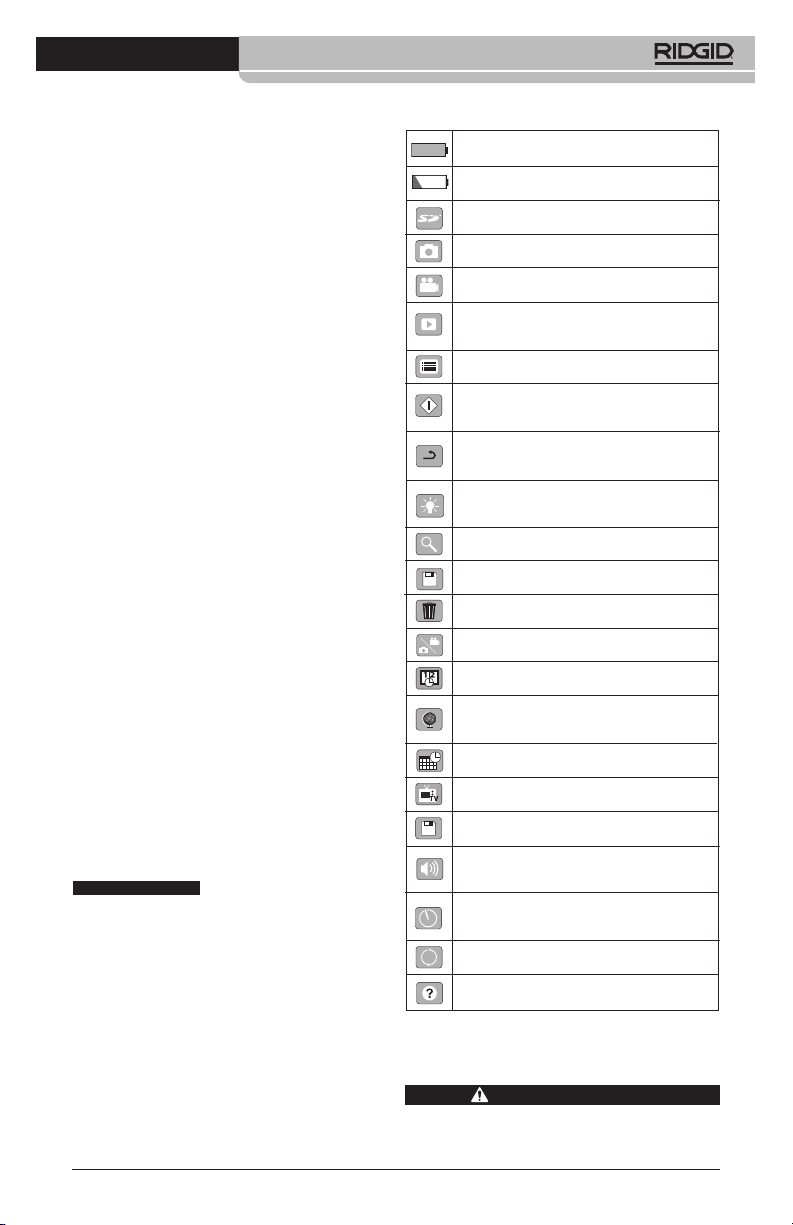
Caméra d’inspection micro CA-300
Avertissement FCC
Cet appareil a été testé et homologué au titre
des limites établies pour les dispositifs
numériques Catégorie B sous l’article 15 de la
réglementation FCC. Ces limites ont été éta blies afin d’assurer une protection raisonnable
contre les interférences nuisibles dans les
installations résidentielles.
Ce matériel produit, utilise et risque d’émettre
des fréquences radio et, faute d’une installation et utilisation conforme aux instructions,
risque de produire des interférences nuisibles aux communications radio.
Cependant, il n’est pas garanti qu’une telle interférence n’aura pas lieu dans une installation
donnée.
Si la mise en marche et l’arrêt de ce matériel
devait éventuellement déterminer qu’il produit des interférences nuisibles à la réception radio ou télévision locale, il est conseillé à
l’utilisateur d’essayer d’éliminer cette interférence selon l’une ou plusieurs des méthodes
suivantes :
• Réorientez ou déplacez l’antenne de réception.
• IAugmentez la distance entre le matériel
et le récepteur.
• Consultez le concessionnaire ou un technicien radio/télé compétent pour obtenir de
l’aide.
Compatibilité électromagnétique (EMC)
La compatibilité électromagnétique d’un produit sous-entend son bon fonctionnement en
présence d’irradiations électromagnétiques
et de décharges électrostatiques, sans interférence électromagnétique de sa part vis-à-vis
des appareils environnants.
AVIS IMPORTANT
RIDGID micro CA-300 est conforme à
l’ensemble des normes EMC applicables.
Cependant, la possibilité d’un éventuel parasitage des appareils environnants ne peut
pas être exclue.
La caméra d’inspection
Icônes
Indicateur de charge – Pile chargée à
100 %.
Indicateur de charge – Pile à 25 % de
charge.
TM
Carte SD
Photo – Mode « photo » activé.
Vidéo – Mode « vidéo » activé.
Lecture – La sélection de cette icône
permet de visualiser et/ou éliminer les images et vidéos sauvegardées.
Menu – La sélection de cette icône permet d’accéder au menu.
Sélection – A partir de la visualisation en
cours, la touche « sélection » permet de
revenir à l’écran de lecture.
Retour – A partir de la visualisation en
cours, la touche « retour » permet de naviguer entre le mode vidéo et le mode photo.
Intensité LED – Les flèches droite et
gauche permettent de moduler l’intensité
lumineuse des LED.
Zoom – Les flèches haute et basse permettent de moduler le zoom de 1x à 2x.
Sauvegardée – Indication que l’image ou
vidéo enregistrée a été sauvegardée.
Corbeille – Icône de confirmation d’effacement.
Mode – Sélection du mode opératoire
(Photo/Vidéo/Lecture).
Horloge – Affichage ou dissimulation de
la date et de l’heure de l’enregistrement.
Langue – Choix de la langue d’affichage
(anglais, français, espagnol allemand, hollandais, italien, etc.).
Horodateur – Cet écran permet de fixer
la date et l’heure de l’enregistrement.
Télé – Sélection du format télé applicable
(NTSC ou PAL) au niveau de la sortie vidéo.
Mise à jour – Accès à la dernière mise à
jour du logiciel.
Haut-parleur/Micro – Interrupteur microphone et haut-parleur en cours d’enregistrement et de lecture.
Arrêt automatique – L’appareil s’éteint
automatiquement au bout de 5, 15 o 60
minutes d’inactivité.
Paramètres de base – Retour aux
paramètres d’origine de l’appareil.
A propos – Affichage de la version du
logiciel.
– Présence d’une carte SD.
Assemblage de l’appareil
AVERTISSEMENT
Respectez les consignes d’assemblage
suivantes afin de limiter les risques de
27
Page 30
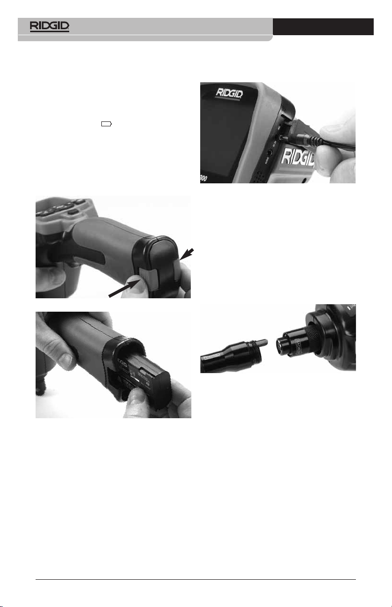
Caméra d’inspection micro CA-300
grave blessure corporelle en cours d’utilisation de l’appareil.
Installation et remplacement
des piles
La pile de la micro CA-300 n’est pas installée
lors de la livraison de l’appareil. Si l’indicateur
de charge affiche , il sera nécessaire de
recharger la pile. Retirez la pile avant tout
remisage prolongé afin d’éviter les risques
de fuite.
1. Comprimez les languettes de part et
d’autre du couvercle du logement de pile
pour le retirer (Figure 5). Au besoin, re-
tirez la pile.tirez la pile.
Figure 5 – Couvercle du logement de pile
3. Introduisez la fiche du transformateur
dans la prise cylindrique « DC 5V » de
l’appareil.
Figure 7 – Alimentation sur secteur
Branchement du câble de tête
de caméra et de ses rallonges
Avant de pouvoir utiliser la caméra d’in spec tion micro CA-300, il est nécessaire d’y bran cher le câble de tête de caméra. Pour ce
faire, alignez la clé de la fiche du câble sur l’ergot correspondant de l’appareil (Figure 8).
Une fois que ces deux éléments sont bien engagés, vissez manuellement la molette de
verrouillage du câble sans trop forcer.
Figure 6 – Retrait/introduction de la pile
2. Introduisez la pile dans l’appareil, contacts en premier.
3. Réinstallez le couvercle du logement de
pile.
Alimentation sur secteur
Il est également possible d’alimenter la caméra
d’inspection micro CA-300 sur secteur à l’aide
du transformateur fourni.
1. Ouvrez le couvercle des fiches du côté
droit de l’appareil (Figure 3).
2. Avec les mains sèches, branchez le
transformateur sur la prise de courant.
28
Figure 8 – Connexion du câble
Des rallonges de câble de 3 pieds (90 cm) et
de 6 pieds (180 cm) de long sont disponibles
pour éventuellement atteindre une longueur
maximale de 30 pieds (9 m). Pour ajouter
des rallonges, dévissez la molette de verrouillage, puis déconnectez le câble de tête de
caméra de l’appareil. Raccordez la rallonge de
câble comme indiqué plus haut (Figure 8).
Ensuite, engagez la clé du câble de tête de
caméra dans l’ergot de la fiche de la rallonge,
puis serrez la molette manuellement pour verrouiller la connexion.
Montage des accessoires
Les trois accessoires livrés avec l’appareil
(crochet, aimant, miroir) se montent tous de la
même manière.
Pour monter un accessoire, tenez la tête de
caméra comme indiqué à la Figure 9, puis
Page 31

Caméra d’inspection micro CA-300
engagez l’extrémité semi-circulaire de l’ac cessoire sur les plats de la tête. Ensuite,
tournez l’accessoire d’un quart de tour pour le
verrouiller.
Accessoire
Figure 9 – Montage des accessoires
Installation de la carte SD
TM
Ouvrez le couvercle des fiches du côté gauche
de l’appareil (Figure 4) pour accéder au loge-
ment de carte SD. Introduisez la carte SD
dans le logement avec ses contacts orientés
vers vous et sa partie biaise vers le bas
(Figure 10). Ne forcez pas la carte, car elle ne
peut être introduite que dans ce sens. Lors qu’une carte SD est installée, une petite icône
de carte SD apparaît en haut et à gauche de
l’écran, en même temps que le nombre d’images ou la longueur de vidéo qu’elle peut
contenir.
1. Assurez-vous que l’appareil est éteint.
2. Retirez la pile afin de l’examiner pour
signes de détérioration. Au besoin, remplacez la pile. Ne jamais tenter d’ali menter l’appareil à l’aide d’une pile endommagée.
3. Nettoyez soigneusement l’ensemble du
matériel. Cela facilitera à la fois son examen et sa manipulation.
4. Examinez la caméra d’inspection micro
CA-300 pour signes d’éléments endommagés, usés, manquants ou grippés,
voire pour toute anomalie susceptible de
nuire au bon fonctionnement et à la sécurité de l’appareil.
5. Examinez la lentille de la tête de caméra
pour signes de condensation. Le cas
échéant, n’utilisez pas la caméra avant
que cette condensation ait eu le temps de
s’évaporer.
6. Examinez le câble sur toute sa longueur
pour signes de fissuration ou de détérioration. Un câble endommagé risque de
laisser pénétrer l’eau à l’intérieur de l’ap pareil et d’augmenter les risques de choc
électrique.
7. Assurez-vous du serrage adéquat des
connexions entre l’appareil, les rallonges
éventuelles et le câble de la tête de
caméra afin de garantir l’étanchéité de
l’ensemble. Vérifiez le bon assemblage
de l’ensemble.
8. Assurez-vous de la présence, de la bonne
fixation et de la lisibilité de l’étiquette signalétique de l’appareil (Figure 11).
Figure 10 – Introduction de la carte SD
Contrôle préalable de
l’appareil
AVERTISSEMENT
Contrôlez l’état de la caméra d’in spec tion avant chaque utilisation afin de corriger d’éventuelles anomalies et limiter le
risque de choc électrique, de blessure
corporelle et de détérioration de l’ap pareil.
Figure 11 – Etiquette signalétique
9. Si vous constatez une anomalie en cours
de l’examen, n’utilisez pas la caméra
d’inspection avant d’y avoir remédié.
10. Avec les mains sèches, réinstallez la pile.
29
Page 32

Caméra d’inspection micro CA-300
11. Appuyez sur la touche marche/arrêt pendant une seconde. L’éclairage de la tête
de caméra devrait alors s’allumer, et
l’écran d’accueil devrait apparaître. Dès
que l’appareil est prêt, l’image captée
en temps réel par la tête de caméra devrait apparaître à l’écran. Si aucune
image n’apparaît, consultez le chapitre
Dépannage.
12. Appuyez à nouveau sur la touche mar che/arrêt pendant une seconde pour
éteindre l’appareil.
Préparation de
l’appareil et du chantier
AVERTISSEMENT
Préparez la caméra d’inspection micro
CA-300 et le chantier selon la procédure suivante afin de limiter les risques
de choc électrique, d’entraînement ou
autres accidents, et éviter d’endom mager l’appareil ou le réseau.
1. Examinez les lieux pour :
• Un éclairage suffisant
• La présence de liquides, émanations
ou poussières inflammables qui risquerait d’exploser. Le cas échéant, ne
travaillez pas dans le secteur avant
d’en avoir identifié et éliminé les
sources potentielles. La caméra d’inspection micro CA-300 n’est pas antidéflagrante et risque d’émettre des étincelles.
• Un endroit au sec, de niveau, stable et
dégagé pour l’utilisateur. N’utilisez pas la
caméra d’inspection lorsque vous avez
les pieds dans l’eau.
2. Examinez l’endroit ou l’objet à inspecter
afin de déterminer si ou non la caméra
d’inspection micro CA-300 est adaptée à
l’intervention envisagée.
• Vérifiez les points d’accès de l’objet. Le di-
amètre minimal nécessaire pour le passage de la tête de caméra de 17 mm de diamètre est d’environ
• Déterminez la distance jusqu’au point
d’inspection. Des rallonges peuvent être
3
/4(19 mm) po.
ajoutées à la caméra pour atteindre une
distance maximale de 30 pieds (9 m).
• Déterminez s’il existe des obstacles qui
seraient susceptibles d’imposer des virages très serrés au câble. Le câble de
la caméra d’inspection est câble de négocier des coudes d’un rayon maxi de 5
pouces (127 mm) sans être endommagé.
• Assurez-vous que l’objet à inspecter
n’est pas sous tension. Le cas échéant,
il sera nécessaire de couper le courant
dans cette zone afin de limiter les ris ques de choc électrique. Appliquez les
mesures de verrouillage appropriées
afin d’empêcher la remise en tension du
réseau en cours d’inspection.
• Evaluez les risques de rencontrer des
liquides en cours d’inspection. Le câble
et la tête de caméra sont étanches
jusqu’à une profondeur de colonne
d’eau de 10 pieds (3 m). Une profon deur supérieure risque de provoquer
des fuites au niveau du câble ou de la
tête de caméra et augmenterait les
risques de choc électrique et de détérioration du matériel. L’appareil lui-même
bénéficie d’une résistance à l’eau IP65,
mais ne doit pas être immergé.
• Établissez la présence éventuelle de
produits chimiques, notamment lors de
l’inspection des évacuations. Il faut se
familiariser avec les précautions d’us age applicables à chaque type de produit chimique rencontré. Consultez le
fabricant du produit chimique en question pour les renseignements correspondants. Aussi les produits chimiques risquent-ils d’endommager la
caméra d’inspection.
• Déterminez la température ambiante et
celle des objets environnants. Les limites de température opérationnelle de la
caméra d’inspection sont situées entre
32 et 130 °F (0 à 55 °C). L’utilisation de
l’appareil à des températures ambiantes
hors de cette plage ou sa mise en contact avec des objets plus chauds ou
plus froids que les limites indiquées risquerait d’endommager la caméra.
• Déterminez si la zone à inspecter contient des composants mécaniques. Le
cas échéant, ces éléments devront être
désactivés durant l’inspection afin de réduire les risques d’enchevêtrement.
Appliquez les procédures de verrouil-
30
Page 33

Caméra d’inspection micro CA-300
lage appropriées afin d’empêcher le
mouvement de ces mécanismes en
cours d’inspection.
Si la caméra d’inspection micro CA-300 n’est
pas adaptée aux travaux envisagés, consultez
le catalogue en ligne www.RIDGID.com ou
www.RIDGID.eu pour la liste complète des
produits RIDGID.
3. Assurez-vous que la caméra d’inspection micro CA-300 a bien été correctement examinée.
4. Montez les accessoires adaptés à l’appli cation envisagée.
Utilisation de l’appareil
AVERTISSEMENT
Prévoyez systématiquement des lunettes
de sécurité afin de protéger vos yeux
contre la projection de débris.
Respectez le mode d’emploi de l’appareil
afin de limiter les risques de choc électrique, enchevêtrement et autres accidents.
1. Assurez-vous que la caméra d’inspection et le chantier ont été correctement
préparés et qu’il n’y a pas de spectateurs ou autres sources de distraction
sur les lieux.
2. Appuyez sur la touche marche/arrêt pendant deux secondes. L’éclairage de la
tête de caméra devrait s’allumer, suivi de
l’affichage de l’écran d’accueil. Cet écran
restera apparent le temps de l’initialisation
de l’appareil, puis sera remplacé par
l’écran vidéo affichant l’image captée en
temps réel par la tête de caméra.
Ecran vidéo
La majeure partie de l’inspection se fait sur
l’écran vidéo. Celui-ci affiche l’image captée par
la tête de caméra en temps réel. Cet écran
permet à la fois de zoomer, de régler l’intensité
des LED, et d’importer les images et vidéos
captées.
En haut de l’écran se trouve une barre d’état
indiquant le mode opératoire utilisé, tandis
que la barre d’information en bas de l’écran affiche l’état de la pile, l’heure, la date et la
présence éventuelle d’une carte SD
Figure 13 – Ecran vidéo
Lors de sa mise sous tension, la caméra d’inspection se met par défaut en mode « photo ».
Vous pouvez appuyez sur la touche « menu »
à tout moment pour accéder au menu. Le
menu sera superposé sur l’image vidéo.
Servez-vous des flèches horizontales pour
changer de mode opératoire. Servez-vous des
flèches verticales pour naviguer parmi les
options au menu, puis appuyez sur la touche
« Sélection » pour arrêter votre choix.
TM
.
Barre
d’état
Barre
d’information
Figure 12 – Ecran d’accueil
(A noter que la version sera mise à jour à chaque
mise à jour du logiciel).
Figure 14 – Affichage de sélection de mode
opératoire
3. Si les autres paramètres de la caméra
d’inspection (horodateur, langue, date et
heure, sortie télé, mise à jour de logiciel,
haut-parleur/microphone, arrêt automa-
31
Page 34

Caméra d’inspection micro CA-300
tique, remise aux paramètres de base)
doivent être réglés à leur tour, veuillez
vous reporter au chapitre Menu.
4. Avant d’introduire la tête de caméra dans
la zone visée, il sera parfois nécessaire
de préformer son câble afin de franchir
les coudes ou obstacles potentiels. Ne jamais tenter de couder le câble sur un
rayon inférieur à 5", car cela pourrait l’endommager. Lors des inspections effectuées dans des endroits sombres, allumez les LED avant d’y introduire la tête
de caméra.
Ne jamais forcer le câble lors de son
insertion ou retrait, car cela pourrait endommager à la fois l’appareil et la zone
inspectée. Ne jamais utiliser la tête de
caméra pour modifier ou dégager son
propre passage ou dégager des obstacles éventuels ; voire en tant qu’autre
chose qu’un appareil d’inspection. Cela
risquerait d’endommager l’appareil électrique ainsi que la zone inspectée.
Réglage de l’image
Réglage de l’éclairage LED : Avec l’écran
en mode « vidéo », appuyez sur les flèches
horizontales pour augmenter ou diminuer
l’éclairage LED. Un témoin d’intensité d’é clairage sera affiché à l’écran pendant le
réglage.
Figure 15 – Réglage des LED
Zoom : La caméra d’inspection micro CA-
300 dispose d’un zoom numérique de 2x.
Avec l’écran en mode « vidéo », appuyez sur
les flèches verticales pour rapprocher ou
éloigner l’image. Un témoin de zoom sera affiché à l’écran pendant le réglage.
Figure 16 – Réglage du zoom
Rotation d’image : Il est possible, au be-
soin, de faire tourner l’image (photo ou vidéo)
en sens anti-horaire par tranches de 90° à la
fois en appuyant sur la touche de rotation
d’im age .
Capture d’image
Capture de photos
Avec l’écran en mode « vidéo » et l’icône
« photo » allumée en haut et à gauche de
l’écran, appuyez sur la touche « obturateur »
pour prendre une photo des lieux. Une icône
de sauvegarde apparaîtra momentanément à l’écran pour indiquer que la photo
saisie a été sauvegardée dans la mémoire interne de l’appareil ou sur sa carte SD
Capture de vidéos
Avec l’écran en mode « vidéo » et l’icône
« vidéo » allumée en haut et à gauche de
l’écran, appuyez sur la touche « obturateur »
pour lancer l’enregistrement vidéo. Un cadre
rouge clignotera autour de l’icône « vidéo »
pendant tout l’enregistrement, et la durée de
l’enregistrement sera affichée en haut de
l’écran. Appuyez à nouveau sur la touche
« obturateur » pour arrêter l’enregistrement.
La sauvegarde de la vidéo dans la mémoire
interne de l’appareil peut prendre quelques
secondes.
La micro CA-300 est équipée d’un ensemble
microphone/haut-parleur incorporé qui permet d’enregistrer et de réécouter d’éventuels
commentaires accompagnant l’enregistrement
vidéo. Un casque d’écoute avec microphone
est prévu pour éventuellement se substituer à
l’ensemble audio incorporé à l’appareil. Ce
casque se branche dans la prise audio située
sur le flanc droit de la caméra.
5. Lorsque l’inspection est terminée, retirez
précautionneusement la tête de caméra
de la zone inspectée.
TM
.
32
Page 35

2. Lors de la relecture de photos, l’utilisateur
3. Lors de la relecture d’une vidéo, l’utili -
Figure 17 – Ecran en mode « vidéo »
Menu
Vous pouvez appuyez sur la touche « menu »
à tout moment pour accéder au menu. Le
menu se superposera sur l’écran vidéo. A partir du menu, l’utilisateur peut soit changer de
mode opératoire ou accéder au menu des
paramètres.
Le menu des paramètres affiche plusieurs
catégories (Figure 18) de choix. Les flèches
horizontales permettent d’aller d’une catégorie à l’autre. Les flèches verticales permettent de naviguer parmi les articles affichés.
La catégorie sélectionnée sera encadrée en
rouge vif. Une fois que le paramètre voulu
est atteint, appuyez sur la touche « sélection »
pour appliquer ce choix. Toute modification
est automatiquement sauvegardée.
Lorsque vous êtes en mode « menu », vous
pou vez appuyer sur la touche « retour »
pour revenir à l’écran précédent ou sur la
touche « menu » pour sortir du menu et
retrouver l’écran vidéo.
Vignette horaire
Celle-ci permet d’afficher ou de masquer
l’heure et la date de l’enregistrement.
Langue
Sélectionner l’icône de langue dans le menu,
puis appuyez sur « sélection ». Parcourez les
diverses langues offertes à l’aide des flèches
verticales , puis appuyez à nouveau sur
« sélection » pour arrêter votre choix .
Caméra d’inspection micro CA-300
« sélection » . Sélectionnez ensuite soit
« Photo » ou « Vidéo » pour revoir le fichier
souhaité. Le mode « re lecture » est l’interface
des fichiers sauvegardés. Il ira par défaut au
dernier fichier enregistré.
aura la possibilité de parcourir toutes les
images sauvegardées, d’effacer une
image quelconque et d’afficher les informations jointes au fichier.
sateur aura la possibilité de naviguer
parmi les différentes vidéos, les arrêter,
les relancer et les supprimer. A noter
qu’en l’absence d’une carte SD™, l’uti lisateur ne pourra qu’accéder aux images et vidéos de la mémoire interne de
l’appareil.
Effacement des fichiers
Pour effacer une image ou une vidéo
à partir du mode « relecture », appuyez
sur la touche « menu ». Le dialogue de
con firm ation permet à l’utilisateur d’effacer les fichiers inutiles. L’icône activée
est alors encadrée de rouge. La navigation se fait à l’aide des flèches .
Figure 18 – Menu des paramètres
Mode « relecture »
1. Pour revoir un enregistrement à partir de
l’écran en cours, appuyez sur la touche
Date et Heure
Sélectionnez « Date » ou « Heure » pour mettre ces paramètres à jour. Sélectionnez
« Format Date » ou « Format Heure » pour
modifier leur affichage.
Sortie télé
Sélectionner « NTSC » ou « PAL » en fonction
du format du téléviseur utilisée. L’écran de
l’appareil s’éteindra et l’image sera transmise
au téléviseur. Pour obtenir une image en
temps réel sur l’appareil, appuyez sur la touche
marche/arrêt et interrompre le transfert
d’image.
33
Page 36

Caméra d’inspection micro CA-300
Mise à jour de logiciel
Utiliser la « mise à jour de logiciel » pour télé charger la version la plus récente du logiciel.
Ce logiciel devra être téléchargé sur une carte
SD™ avant d’être introduit dans l’ap pareil.
Toutes mises à jour éventuelles seront dis ponibles sur www.RIDGID.com.
Haut-parleur
Sélectionnez l’icône du haut-parleur à partir du
menu, puis appuyez sur « sélection » .
Sélectionnez « marche » ou « arrêt » à l’aide
des flèches verticales pour allumer ou
éteindre le haut-parleur pendant la relecture de
la vidéo.
Arrêt automatique
Sélectionnez l’icône d’arrêt automatique, puis
appuyez sur « sélection » . Sélectionnez
« désactiver » pour neutraliser la fonction d’ar rêt automatique. Sélectionnez « 5 minutes »,
« 15 minutes » ou « 60 minutes » pour que
l’ap pareil s’éteigne automatiquement au bout
de 5, 15 ou 60 minutes d’inactivité. A noter que
la fonction d’arrêt automatique sera temporairement neutralisée lors de l’enregistrement
ou la relecture d’une vidéo.
Retour aux paramètres
d’origine
Sélectionnez l’icône de retour aux paramètres
d’origine, puis appuyez sur « sélection » .
Con firmez votre choix en sélectionnant « Oui »,
puis en appuyant à nouveau sur « sélection »
. L’appareil reviendra ainsi aux paramètres
du fabricant.
A propos
Sélectionnez la fonction « A propos » (About)
pour afficher la version actuelle du logiciel
micro CA-300, ainsi que les licences et paten tes applicables.
Transfert d’images vers un
ordinateur
Avec l’appareil en marche, connectez le micro
CA-300 à l’ordinateur via un câble USB. La
présence de cet écran sera alors affichée sur
celui du micro CA-300. La mémoire interne et,
le cas échéant celle de la carte SD™, apparaîtront en tant que fichiers distincts sur l’ordi nateur, désormais accessibles en tant qu’unités de stockage USB standards. Cela permet
de copier ou d’effacer les fichiers à partir de
l’ordinateur.
Connexion télé
Le câble RCA fourni permet de raccorder la
caméra d’inspection micro CA-300 à un télé viseur ou autre moniteur afin de relire ou enregistrer les images à distance.
Ouvrez le couvercle des prises du côté droit de
l’appareil (Figure 3), puis introduisez le câble
RCA dans la sortie télé. Introduisez l’autre extrémité du câble dans la prise du téléviseur ou
moniteur. Assurez-vous d’avoir sélectionné
le format vidéo (NTSC ou PAL) approprié. Il
sera éventuellement nécessaire de modifier
aussi la source de l’émission avant de pouvoir
visualiser l’image. Choisissez le format de sortie télé approprié au Menu.
Utilisation des accessoires
d’inspection SeeSnake
La caméra d’inspection micro CA-300 est
compatible avec plusieurs types de systèmes
d’inspection SeeSnake, notamment les systèmes microReel, microDrain
Lorsqu’il est utilisé avec ce type de matériel,
l’appareil retient toutes les fonctions décrites
dans le présent manuel. La caméra d’in spec tion micro CA-300 peut également utiliser
d’au tres types de matériel d’inspection
SeeSnake, mais ses fonctions seront alors
limitées à la relecture et à l’enregistrement.
Pour utiliser un système SeeSnake avec l’ap pareil, il sera d’abord nécessaire de déposer
la tête de caméra (ainsi que ses rallonges
éventuelles) de l’appareil. Lors de l’uti lisation
des systèmes microReel, microDrain™,
nanoReel ou systèmes similaires, consultez
leur mode d’emploi pour les consignes de
raccordement et d’utilisation. Pour l’utilisa tion d’autres types de matériel d’inspection
SeeSnake (enrouleurs, moniteurs, etc.), il
sera nécessaire de prévoir un adaptateur
pour raccorder la caméra d’inspection micro
CA-300 au matériel d’inspection SeeSnake.
Une fois ainsi raccordée, la caméra d’in spection micro CA-300 permettra d’afficher
et d’enregistrer les images émises.
Lors de la connexion de l’appareil à du mat ériel d’inspection SeeSnake
nanoReel), branchez le module de connexion de
l’enrouleur sur la connexion de câble de la caméra
d’inspection micro CA-300 en l’alignant parfaitement
(Figure 19).
®
(microReel, microDrain™ ou
®
TM
et nanoReel.
34
Page 37

Figure 19 – Connexion du câble de tête de
AVIS IMPORTANT
caméra
La fiche de connexion est
fragile ; ne jamais la vriller lors de son introduction.
Localisation de la sonde
Lors de l’utilisation d’une sonde (transmetteur
souterrain) avec l’appareil, cette sonde peut
être contrôlée de deux manières. Si l’enrouleur
est équipé d’une clé de sonde, celle-ci permet
d’activer et de désactiver la sonde. Sinon, la
sonde doit être activée en diminuant l’intensité
de l’éclairage LED jusqu’à zéro. Une fois la
sonde localisée, les LED peuvent être remises
à leur intensité initiale afin de poursuivre l’inspection.
Un localisateur RIDGID du type SR-20, SR-60,
®
ou NaviTrack®II réglé à 512 Hz peut
Scout
servir à localiser les divers caractéristiques
de la conduite inspectée.
Figure 20 – Localisation de la sonde de l’en-
rouleur
Pour localiser la sonde, allumez le localisateur
et mettez-le en mode « Sonde ». Balayez le
sol en direction de la position probable de la
sonde jusqu’à ce que le localisateur la détecte. Une fois la sonde repérée, servez-vous
des indications fournies par le détecteur pour
cibler sa position précise. Pour de plus amples
renseignements concernant la localisation des
sondes, consultez le mode d’emploi du localisateur utilisé.
Caméra d’inspection micro CA-300
Entretien
AVERTISSEMENT
Retirez la pile de l’appareil avant toute
intervention.
• Nettoyez la tête de caméra et son câble
systématiquement après chaque utilisation à l’aide d’un savon ou d’un détergeant
non agressif.
• Nettoyez délicatement l’écran de l’appareil
à l’aide d’un morceau de tissu doux et
propre. Evitez de trop frotter.
• Nettoyez les connexions de câble exclusivement avec des tampons imbibés d’al cool.
• Essuyez le boîtier de l’appareil avec un
morceau de tissu sec et propre.
Réarmement
Si l’appareil cesse de fonctionner, appuyez sur
la touche de réarmement qui se trouve sous le
couvercle de prises gauche (Figure 4) en es-
pérant que cela suffira à lui rendre sa fonctionnalité lorsqu’il est rallumé.
Accessoire
AVERTISSEMENT
Seuls les accessoires suivants ont été
conçus pour fonctionner avec la caméra
d’inspection micro CA-300. Toute tentative d’adaptation à la caméra d’inspec tion micro CA-300 d’accessoires prévus
pour d’autres types d’appareils risque
de s’avérer dangereuse.
Accessoires pour caméra d’inspection
numérique micro CA-300
Réf.
catalogue Description
37108 Rallonge de câble de 3 pieds (90 cm)
37113 Rallonge de câble de 6 pieds (90 cm)
37103 Tête de caméra Ø 17 mm avec câble
37098 Câble de tête de caméra Ø 6 mm (1 m)
37093 Câble de tête de caméra Ø 6 mm (4 m)
37123 Pack d’accessoires Ø 17 mm (miroir,
crochet et aiment)
40028 Transformateur de courant
40623 Casque d’écoute avec micro
De plus amples renseignements concernant
les accessoires compatibles avec cet appareil se trouvent dans le catalogue RIDGID
ou sur les sites www.RIDGID.com ou
www.RIDGID.eu.
35
Page 38

Caméra d’inspection micro CA-300
Stockage
La caméra d’inspection micro CA-300 doit
être stockée dans un endroit sec et sous clé à
une température ambiante de -4 °F (-20 °C) à
158 °F (70 °C) et une humidité relative de
15 à 85 %.
Rangez l’appareil, son bloc-piles, son char geur et ses câbles dans un local sous clé,
hors de la portée des enfants et de tout individu non familiarisé avec la caméra d’in spection micro CA-300.
Afin d’éviter les fuites d’acide éventuelles, retirez la pile de l’appareil avant tout stockage
prolongé ou lors de son expédition.
Service après-vente et
réparations
AVERTISSEMENT
Toute intervention mal exécutée risque
de rendre la caméra d’inspection RIDGID
micro CA-300 dangereuse.
Toute révision ou réparation de la caméra
d’inspection micro CA-300 doit être confiée à
un réparateur RIDGID agréé.
Pour localiser le centre d’entretien le plus
proche ou poser une question visant le service après-vente de l’appareil :
• Consultez votre distributeur RIDGID
• Visitez le site www.RIDGID.com ou
www.RIDGID.eu pour localiser l’interlocuteur le plus proche.
• Consultez les services techniques de
RIDGID par mail adressé à rtctechservices@emer son.com ou, à partir des USA
et du Canada exclusivement, en composant le (800) 519-3456.
Recyclage
Certains composants de la caméra d’in spec tion micro CA-300 contiennent des matières
de valeur susceptibles d’être recyclées. Il se
peut que certaines des entreprises de recyclage concernées se trouvent localement.
Disposez de ces composants selon la réglementation en vigueur. Pour de plus amples
renseignements, consultez votre centre de
recyclage local.
A l’attention des pays de la CE :
Ne jamais jeter de matériel électrique à la poubelle !
Selon la norme européenne
2002/96/EC visant les déchets de
matériel électrique et électronique
et son application vis-à-vis de la législation nationale, tout matériel électrique non utilisable
doit être collecté à part et recyclé d’une
manière écologiquement responsable.
Dépannage
SYMPTÔMES CAUSES POSSIBLES SOLUTIONS
L’écran s’allume mais
ne montre pas d’image.
L’éclairage de la tête
de caméra est sombre
même à pleine puissance, l’écran oscille
entre le noir et le blanc,
l’écran couleur s’éteint
en peu de temps.
L’appareil ne s’allume
pas.
36
Mauvaise connexion des câbles.
Tête de caméra endommagée.
Tête de caméra recouverte de débris.
Pile déchargée.
Pile morte.
L’appareil a besoin d’être réarmé.
Vérifier les connexions de câble et les
nettoyer si nécessaire avant de les rebrancher.
Remplacer la tête de caméra.
S’assurer que la tête de caméra n’est
pas encrassée.
Remplacer la pile par une pile chargée.
Remplacer la pile par une pile chargée.
Réarmer l’appareil selon les consignes
de la section « Entretien ».
Page 39

Caméra d’inspection micro CA-300
Sécurité du bloc-piles
et du chargeur
AVERTISSEMENT
Afin de limiter les risques d’accident
grave, familiarisez-vous avec les précautions suivantes avant d’utiliser la
pile ou son chargeur.
Sécurité du chargeur
• N’utilisez le chargeur RIDGID que pour
le rechargement des piles RIDGID re chargeables portées sur la liste des accessoires. D’autres types de piles risquent
d’exploser et provoquer des blessures ou
des dégâts matériels.
• Ne pas introduire d’éléments conduc-
teurs dans le chargeur. Un court-circuit
au niveau des bornes du chargeur risque
de produire des étincelles, voire causer
des brûlures ou provoquer des chocs électriques.
• Ne pas introduire de pile dans un char -
geur après qu’il soit tombé ou endommagé d’une manière quelconque. Un
chargeur endommagé augmenterait les
risques de choc électrique.
• N’utilisez le chargeur qu’à des tempéra-
tures ambiantes situées entre 32 °F
(0 °C) et 122 °F (50 °C). Rangez le chargeur
à des températures ambiantes situées
entre -4 °F (-20 °C) et 104 °F (40 °C). Le
stockage prolongé à une température
supérieure à 104 °F risquerait de nuire à la
capacité de charge des piles. Un bon entretien assurera le bon fonctionnement
des piles. Un manque d’entretien risque
d’entraîner des fuites d’électrolyte, voire
des chocs électriques et des brûlures.
• Prévoyez une source d’alimentation ap-
propriée. Ne tentez pas d’alimenter le
chargeur à l’aide d’un transformateur de
courant ou d’un groupe électrogène. Cela
pourrait endommager le chargeur et provoquer des chocs, incendies ou brûlures
électriques.
• Ne laissez rien recouvrir le chargeur
lors de son fonctionnement. Le bon
fonc tionnement du chargeur nécessite une
ventilation suffisante. Laissez un vide d’au
moins 4" (10 cm) autour du chargeur pour
assurer une ventilation adéquate.
• Débranchez le chargeur dès qu’il ne
sert plus. Cela limitera les risques de
blessure des enfants et des individus non
initiés.
• Débranchez le chargeur avant son net-
toyage ou entretien. Cela limitera les
risques de choc électrique.
• Ne chargez pas de bloc-piles dans un
milieu humide, mouillé ou explosif. Ne
pas exposer l’appareil aux intempéries ou
à la salissure. L’humidité et les contaminants éventuels augmenterait les risques
de choc électrique.
• Ne jamais tenter d’ouvrir le boîtier du
chargeur. Confiez toute intervention éven tu elle à un réparateur agréé.
• Ne portez jamais le chargeur par son
cordon d’alimentation. Cela limitera les
risques de choc électrique.
• Le chargeur RIDGID ne doit être utilisé
par des enfants ou des individus aux capacités physiques, sensorielles ou mentales réduites, voire ceux sans expérience
ou connaissance du produit, que sous la
supervision d’un responsable ou après
avoir obtenu une formation adéquate concernant la manipulation du chargeur
RIDGID.
• Eloignez les enfants et les spectateurs
lors de l’utilisation de ce type de ma tériel. Les distractions pourraient entraîner
une perte de contrôle de l’appareil.
• La révision de cet appareil doit être
confiée à un réparateur agréé disposant
de pièces de rechange identiques aux
pièces d’origine. Afin d’éviter les accidents, tout appareil endommagé devra
être remplacé par le fabricant, son re pré sentant ou un individu qualifié. Ceci
garantira la sécurité de fonctionnement
de l’appareil.
Sécurité des piles
• Recyclez les piles de manière appropriée. Dans la mesure où les piles risquent
d’exploser dès qu’elles sont exposées à
des températures élevées, ne les jetez
pas au feu. Recouvrez les bornes d’adhésif
afin d’éviter leur contact éventuel avec
des éléments conducteurs. Certains pays
disposent d’une réglementation sur le recycle des piles. Le cas échéant, veuillez respecter les normes en vigueur.
• N’introduisez pas de pile fissurée dans
le chargeur. L’utilisation de piles endommagées augmenterait les risques de choc
électrique.
37
Page 40

Caméra d’inspection micro CA-300
• Ne jamais tenter de démonter une pile.
Les piles ne sont pas réparables, et leur
démontage pourrait entraîner des chocs
électriques ou autres blessures.
• Evitez de toucher d’éventuels suinte-
ments de liquide venant d’une pile défectueuse. Ce liquide peut provoquer des
brûlures ou irritations cutanées. En cas
de contact accidentel, rincez l’endroit contaminé à l’eau. En cas de contact avec
les yeux, consultez un médecin.
Description,
caractéristiques
techniques et
équipements de base
Description
Le chargeur RIDGID nº 37088 sert uniquement au rechargement sous 4 ou 5 heures
des piles lithium/ion RIDGID de 3,7 V nº
37083 portés dans la liste des accessoires cidevant. Ce chargeur ne nécessite aucun
réglage.
Figure 21 – Pile et chargeur
Spécifications
Alimentation ................100 – 240 V
Sortie...........................4,2 V
Type de pile.................Li-Ion 3,7 V
Capacité de pile...........4,2 Ah
Tension d’alimentation
(CC).............................3A/1A
Poids........................... 0.4 lbs. (20 g)
Durée de charge .........4 à 5 heures
Refroidissement..........Refroidissement par
convection passive
(sans ventilateur)
Inspection et préparation
du chargeur
AVERTISSEMENT
Inspectez le chargeur et les piles avant
chaque utilisation afin de corriger les
anomalies éventuelles. Installez le char geur selon les consignes suivantes afin
de limiter les risques de choc électrique,
d’incendie ou autres causes d’accident
et de protéger l’appareil et le réseau
contre d’éventuels dégâts. Portez systématiquement une protection oculaire
afin de protéger vos yeux contre la projection éventuelle de débris.
1. Assurez-vous que le chargeur est dé branché avant de l’examiner pour signes
de dégâts ou de modification au niveau
de son cordon d’alimentation, du char geur lui-même ou de sa pile, ainsi que
signes d’éléments brisés, usés, manquants, mal alignés ou grippés. Le cas
échéant, n’utilisez pas le chargeur avant
que les éléments défectueux aient été
réparés ou remplacés.
2. Nettoyez l’appareil selon les indications de
la section Entretien afin d’éliminer toutes
traces de graisse, d’huile et de crasse, notamment au niveau des poignées et commandes. Cela aidera à limiter les risques
de perte de contrôle de l’appareil et lui assurera une meilleure ventilation.
3. Assurez-vous que les plaques et vignettes de sécurité affichées à la fois
sur le chargeur et la pile sont intactes et
lisibles (Figure 22 et Figure 23).
Figure 22 – Vignette du chargeur
38
Page 41

Figure 23 – Vignette de la pile
4. Choisissez un endroit approprié pour le
chargeur. Examinez les lieux pour :
• Un éclairage suffisant.
• Un endroit dégagé, de niveau, stable
et sec pour poser le chargeur. N’utili sez pas cet appareil en milieu humide.
• Une température ambiante appropriée.
Le chargeur et la pile doivent être à une
température située entre 32 °F (0 °C) et
122 °F (50 °C) pour que le chargement
puisse commencer. Si la température
de l’un ou l’autre sort de cette plage à un
moment quelconque durant la recharge,
le rechargement sera interrompu jusqu’à
ce que la température revienne aux
normes.
• Une source d’alimentation appropriée.
Assurez-vous que la fiche de l’appareil
correspond bien à la prise de courant
utilisée.
• Une ventilation adéquate. Le chargeur
a besoin d’un dégagement d’au moins
4" (10 cm) au pourtour pour lui assurer
une ventilation adéquate.
5. Branchez le cordon d’alimentation sur le
chargeur.
6. Avec les mains sèches, branchez le cordon du chargeur sur une source d’ali men tation appropriée.
Méthode de
chargement et
consignes d’utilisation
AVERTISSEMENT
Portez des lunettes de sécurité afin de
protéger vos yeux contre la projection de
débris.
Caméra d’inspection micro CA-300
Respectez les consignes du mode d’emploi afin de limiter les risques de choc
électrique.
NOTA ! Les nouvelles piles atteignent leur pleine
capacité seulement après quelques 5
ou 6 cycles de décharge/recharge.
1. Installez le chargeur selon les consignes
de la section intitulée : Inspection et pré-
paration du chargeur.
2. Le chargeur passe par un stade d’in itiation d’une seconde durant lequel le
témoin LED clignote du rouge au vert,
pour ensuite se mettre en veilleuse (témoin éteint).
3. Avec les mains sèches, positionnez le
bloc-piles sur le chargeur. Le bloc-piles se
mettra en charge automatiquement. Le
témoin rouge restera allumé en continu
tout au long de la charge.
4. Le témoin vert s’allumera dès que la pile
est entièrement rechargée. Retirez la pile.
Une fois la pile chargée, elle peut être
laissée sur le chargeur jusqu’à sa pro chaine utilisation. Il n’y a pas de risque de
surcharger la pile. Une fois la pile entièrement rechargée, le chargeur se met
en automatiquement en mode de maintien.
5. Avec les mains sèches, débranchez le
chargeur en fin de charge.
Consignes de nettoyage
AVERTISSEMENT
Débranchez le chargeur avant toute manipulation. Afin de limiter les risques de
choc électrique, n’utilisez pas d’eau ou
de produits chimiques lors du nettoyage du chargeur ou des piles.
1. Le cas échéant, retirez la pile du chargeur.
2. Eliminez toutes traces de crasse ou de
graisse éventuelles de l’extérieur du
chargeur et de la pile à l’aide d’un tissu
doux ou d’une brosse non métallique.
Accessoires
AVERTISSEMENT
Afin de limiter les risques de blessure
grave, n’utilisez que les accessoires
spécifiquement conçus et recommandés
pour le chargeur RIDGID Li-ion, tels que
ceux indiqués ci-dessous. L’utilisation
39
Page 42

Caméra d’inspection micro CA-300
avec ce chargeur RIDGID Li-ion d’ac cessoires prévus pour d’autres types
d’appareil pourrait s’avérer dangereuse.
Réf.
catalogue Description
37088 Chargeur micro CA-300
37083 Pile Li-ion de 3,7 V pour micro CA-300
30758 Chargeur microEXPLORER
30198 Pile Li-ion de 3,7 V pour
Des renseignements complémentaires concernant les accessoires spécifiquement destinés à ce type de chargeur se trouvent dans
le catalogue RIDGID ou sur les sites
www.RIDGID.com et www.RIDGID.eu.
microEXPLORER
Stockage
Stockez le chargeur et les piles dans un endroit sec, sous clé et hors de la portée des enfants ou des individus non familiarisés avec le
fonctionnement de ces appareils.
Les piles et le chargeur doivent être protégés
contre les chocs importants, l’eau et l’humidité, la poussière et l’encrassement, les températures extrêmes et les solutions ou
vapeurs chimiques.
Un stockage long terme à des températures
supérieures à 104 ºF (40 °C) risquerait de
diminuer la capacité de charge du bloc-piles
de manière permanente.
Service après-vente et
réparations
AVERTISSEMENT
Toute intervention mal exécutée risque
de rendre la caméra d’inspection micro
CA-300 dangereuse.
Ni le chargeur, ni les piles ne contiennent
d’éléments remplaçables. Ne tentez pas d’ouvrir le chargeur ou les piles pour remplacer
des piles ou nettoyer des composants internes.
Toute révision ou réparation de l’appareil doit
être confiée à un réparateur RIDGID agréé.
Pour obtenir les coordonnées du réparateur
RIDGID le plus proche et poser d’éventuelles
questions concernant la révision ou la réparation ce l’appareil, veuillez :
• Consultez votre distributeur RIDGID.
• Visitez le site www.RIDGID.com ou
www.RIDGID.eu pour localiser l’inter locuteur le plus proche.
• Consultez les services techniques de
RIDGID par mail adressé à rtctechservices@emerson.com ou, à partir des USA
ou du Canada exclusivement, en composant le (800) 519-3456.
Recyclage
RIDGID®participe au programme
Call2Recycle
chargeable Battery Recycling
Cor poration (RBRC). En tant que
participant, RIDGID paye les frais
de recyclage des piles rechargeables RIDGID.
Aux Etats-Unis et au Canada, RIDGID et
d’autres fournisseurs de piles utilisent le
réseau du programme Call2Recycle et ses
plus de 30 000 points de collecte pour
récupérer et recycler leurs piles rechargeables. Ceci aide à préserver l’environnement
et conserver nos ressources naturelles.
Veuillez déposer vos piles usagées dans un
point de collecte afin de les faire recycler.
Appelez le numéro vert indiqué sur la vignette
RBRC (1.800.822.8837) ou allez au site
www.call2recyle.org pour localiser le point de
collecte le plus proche.
Pays de la CE : Les piles et bloc-piles défectueux ou hors d’âge doivent être recyclés
selon les modalités du décret 2006/66/EEC.
®
géré par la Re -
40
Page 43

microCA-300
Cámara de inspección
micro CA-300
ADVERTENCIA
Antes de utilizar este aparato, lea
detenidamente su Manual del
Operario. Pueden ocurrir descargas
eléctricas, incendios y/o graves lesiones si no se comprenden y siguen
las ins truc ciones de este manual.
Cámara de inspección micro CA-300
Apunte aquí el número de serie del aparato, que se encuentra en su placa de características.
N° de
serie
Page 44

Cámara de inspección micro CA-300
Índice
Simbología de seguridad ..................................................................................................43
Seguridad general
Seguridad en la zona de trabajo .....................................................................................43
Seguridad eléctrica .........................................................................................................43
Seguridad personal ........................................................................................................43
Uso y cuidado del aparato ..............................................................................................44
Servicio............................................................................................................................44
Seguridad específica
Seguridad de la Cámara de inspección micro CA-300 ...................................................44
Descripción, especificaciones y equipo estándar
Descripción......................................................................................................................45
Especificaciones..............................................................................................................45
Equipo estándar ..............................................................................................................46
Mandos............................................................................................................................46
Comunicado de la FCC (Federal Communications Commission de los EE.UU.) ..............47
Compatibilidad electromagnética (CEM) .........................................................................47
Íconos..................................................................................................................................47
Ensamblaje del aparato
Instalación y reemplazo de la batería..............................................................................48
Alimentación eléctrica .....................................................................................................48
Instalación del cable del formador de imágenes y de cables de extensión ....................48
Acoplamiento de accesorios ..........................................................................................49
Instalación de una tarjeta SD™.......................................................................................49
Inspección previa al funcionamiento ...............................................................................49
Preparación del aparato y de la zona de trabajo.............................................................50
Instrucciones de funcionamiento.....................................................................................51
Pantalla en vivo...............................................................................................................51
Ajuste de la imagen.........................................................................................................52
Toma de imágenes ..........................................................................................................52
Menú ...............................................................................................................................53
Indicación visual de fecha y hora ....................................................................................54
Idioma..............................................................................................................................54
Fecha y hora ..................................................................................................................54
Salida de TV (TV Out).....................................................................................................54
Actualización del Firmware .............................................................................................54
Altavoz.............................................................................................................................54
Apagado automático .......................................................................................................54
Vuelta a la configuración de fábrica ................................................................................54
Acerca de ........................................................................................................................54
Transferencia de imágenes a una computadora.............................................................54
Conexión a TV.................................................................................................................54
Utilización con equipos de inspección SeeSnake
Mantenimiento
Función de re-alistar........................................................................................................56
Accesorios..........................................................................................................................56
Almacenamiento ................................................................................................................56
Servicio y reparaciones.....................................................................................................56
Eliminación del equipo ......................................................................................................56
Detección de averías .........................................................................................................57
Seguridad del cargador de baterías y de la batería ........................................................57
Descripción y especificaciones .......................................................................................58
Inspección y preparación del cargador de baterías .......................................................58
Procedimiento de carga e instrucciones de funcionamiento ........................................59
Instrucciones de limpieza ................................................................................................60
Accesorios..........................................................................................................................60
Almacenamiento ................................................................................................................60
Servicio y reparación.........................................................................................................60
Eliminación de las baterías ...............................................................................................61
Garantía de por vida...................................................................................carátula posterior
*Traducción del manual original
®
................................................................55
42
Page 45

Cámara de inspección micro CA-300
Simbología de seguridad
En este manual del operario y en el aparato mismo encontrará símbolos y palabras de advertencia que comunican importante información de seguridad. Para su mejor comprensión, en esta sección se describe el significado de estos símbolos.
Este es el símbolo de una alerta de seguridad. Sirve para prevenir al operario de las lesiones
corporales que podría sufrir. Obedezca todas las instrucciones que acompañan a este símbolo
de alerta para evitar lesiones o muertes.
PELIGRO
ADVERTENCIA
CUIDADO
AVISO
Este símbolo de PELIGRO advierte de una situación de riesgo o peligro que, si no se
evita, ocasionará la muerte o graves lesiones.
Este símbolo de ADVERTENCIA advierte de una situación de riesgo o peligro
que, si no se evita, podría provocar muertes o lesiones graves.
Este símbolo de CUIDADO previene de una situación de riesgo o peligro que, si no
se evita, podría ocasionar lesiones leves o menores.
Un AVISO advierte de la existencia de información relacionada con la protección de un bien
o propiedad.
Este símbolo significa que, antes de usar el equipo, es necesario leer detenidamente su ma nual del operario. Este manual contiene importante información acerca del funcionamiento
apropiado y seguro del equipo.
Este símbolo señala que durante la manipulación y el funcionamiento de este aparato, con
el fin de evitar lesiones oculares, el operario debe ponerse siempre anteojos o gafas de seguridad con viseras laterales.
Este símbolo indica que el aparato en uso, sus engranajes y piezas movibles, pueden aplastar manos, dedos u otras partes de su cuerpo.
Este símbolo advierte que podrían ocurrir descargas eléctricas.
Información de
seguridad general
ADVERTENCIA
Lea todas las instrucciones y advertencias. Pueden ocurrir golpes eléctricos,
incendios y/o lesiones graves si no se si guen y respetan las instrucciones y advertencias detalladas a continuación.
¡GUARDE ESTAS INSTRUCCIONES!
Seguridad en la zona de trabajo
• Mantenga su área de trabajo limpia y
bien iluminada. Las zonas desordenadas
u oscuras pueden provocar accidentes.
• No haga funcionar el aparato en atmós-
feras explosivas, es decir, en presencia de líquidos, gases o polvo inflama bles. El aparato podría generar chispas
que pueden inflamar estos combustibles.
• Mientras haga funcionar este equipo,
apártese de niños y transeúntes. Cual quier distracción puede hacerle perder el
control del aparato.
Seguridad eléctrica
• Evite el contacto de su cuerpo con artefactos conectados a tierra tales como
cañerías, radiadores, estufas o cocinas,
y refrigeradores. Aumenta el riesgo de
que se produzca una descarga eléctrica
cuando su cuerpo ofrece conducción a
tierra.
• No exponga el aparato a la lluvia o a la
humedad. Cuando a un aparato le entra
agua, aumenta el riesgo de que se produzcan descargas eléctricas.
Seguridad personal
• Manténgase alerta, preste atención a
lo que está haciendo y use sentido
común cuando trabaje con cualquier
aparato. No lo use si está cansado o se
encuentra bajo la influencia de drogas, alcohol o medicamentos. Sólo un breve descuido mientras hace funcionar un aparato
puede resultar en lesiones graves.
• No trate de extender su cuerpo para al-
canzar algo. Mantenga sus pies firmes
en tierra y un buen equilibrio en todo
momento. Así se ejerce mejor control
sobre la herramienta en situaciones inesperadas.
43
Page 46

Cámara de inspección micro CA-300
• Use el equipo de protección personal
que corresponda. Siempre use protec-
ción para sus ojos. Al ponerse mascarilla
para el polvo, calzado de seguridad antideslizante, casco duro o protección para
los oídos, según las circunstancias, usted
evitará lesionarse.
Uso y cuidado del aparato
• No fuerce el aparato. Use el equipo correcto para el trabajo que se dispone a
realizar. El aparato adecuado hará el tra-
bajo mejor y de manera más segura, a la
velocidad para la cual fue diseñado.
• Si el interruptor del aparato no lo en-
ciende o no lo apaga, no utilice el aparato. Cualquier herramienta que no
pueda ser controlada mediante su interruptor constituye un peligro y debe ser
reparada.
• Desconecte la batería del aparato antes
de efectuarle ajustes, cambiarle accesorios o almacenarlo. Estas medidas pre-
ventivas reducen el riesgo de accidentes y
lesiones.
• Almacene los aparatos eléctricos que
no estén en uso fuera del alcance de
niños y no permita que los hagan funcionar personas sin capacitación o que
no hayan leído estas instrucciones. Las
herramientas son peligrosas en manos
de inexpertos.
• Hágale al aparato el mantenimiento de-
bido. Revise que no le falten piezas y
que no tenga partes quebradas o deterioradas que podrían afectar su buen
funciona mien to. Si está dañado, antes de
usarlo, hágalo componer. Los equipos en
malas condiciones causan numerosos
acciden tes.
• Utilice el aparato y sus accesorios en
conformidad con estas instrucciones,
teniendo en cuenta las condiciones imperantes y las tareas que realizará.
Cuando se emplea una herramienta para
efectuar trabajos que no le son propios,
se crean situaciones peligrosas.
• Emplee únicamente los accesorios que
han sido recomendados por el fabricante para usarse con este aparato.
Los accesorios aptos para un cierto equipo
pueden tornarse peligrosos si se utilizan en
conjunción con otros equipos.
• Mantenga todos los mangos del aparato
secos y limpios, sin grasa o aceite. De
44
este modo usted no perderá el control
sobre la herramienta.
Servicio
• El servicio de este equipo debe encomendarse a técnicos calificados que
empleen únicamente repuestos legítimos. Sólo así se garantiza la continua se-
guridad de la herramienta.
Información de
seguridad específica
ADVERTENCIA
Esta sección entrega información de seguridad específica para esta cámara de
inspección.
Antes de utilizar la Cámara de inspección micro CA-300 de RIDGID®, lea estas
instrucciones detenidamente para prevenir choques eléctricos y otras lesiones
de gravedad.
¡GUARDE ESTAS INSTRUCCIONES!
El maletín de la Cámara de inspección micro
CA-300 cuenta con un compartimiento especial para conservar este manual al alcance
del operario.
Seguridad de la cámara de
inspección micro CA-300
• No exponga el visualizador al agua o
llu via. Si le llegase a entrar agua, podría ocasionar descargas eléctricas. El
formador de imágenes de la micro CA-300
y su cable son a prueba de agua hasta los
10 pies (3 m). El visualizador, en cambio, no
lo es.
• No ponga la Cámara de inspección mi -
cro CA-300 en sitio alguno que pu diera
estar bajo tensión o con corriente. Esto
aumenta los riesgos de que ocurran des cargas eléctricas.
• No ponga la Cámara de inspección
micro CA-300 en sitios donde haya
piezas en movimiento. Podría enredarse
en ellas y lesionarlo.
• Jamás use este aparato para realizar
una auscultación corporal o médica.
Éste no es un instrumento médico y podría
causar lesiones.
• Emplee siempre el equipo de protec-
ción personal adecuado cuando uti lice
la Cámara de inspección micro CA-300.
Page 47

Cámara de inspección micro CA-300
Los desagües y las zonas aledañas podrían contener sustancias químicas, bacterias u otras materias que podrían resultar tóxicas, infecciosas, o causar quemaduras u otras lesiones. Al hacer fun-
cionar este equipo, póngase siempre
ga fas o anteojos de seguridad y guan tes –ya sea de látex o de goma-, y otros
protectores como visera facial, ropa de
seguridad, respiradores y/o calzado con
punteras de acero.
• Mantenga una buena higiene. Después
de usar la Cámara de inspección micro
CA-300 para inspeccionar cañerías que
podrían contener sustancias y bacterias
peligrosas, lávese sus manos y las otras
partes de su cuerpo que hayan quedado
expuestas al contenido del desagüe, con
agua caliente y jabón. No coma ni fume
mientras manipula la Cámara de inspección micro CA-300. Así evita contaminarse
con materiales tóxicos o infecciosos.
• No opere la Cámara de inspección micro
CA-300 si usted, el operario, o este apa rato estarán parados sobre agua. Ocu -
rren descargas eléctricas cuando se hace
funcionar un aparato eléctrico estando en
contacto con agua.
El folleto de la Declaración de Conformidad de
la Comunidad Europea (890-0011-320.10)
vendrá adosado a este manual cuando se
requiera.
Si tiene cualquier pregunta acerca de este
producto RIDGID
– Contacte al distribuidor RIDGID en su lo-
calidad.
– Por internet visite el sitio
www.RIDGID.com ó www.RIDGID.eu
para averiguar dónde se encuentran los
centros autorizados de RIDGID más
cercanos.
– Llame al Departamento de Servicio Téc -
nico de RIDGID desde EE.UU. o Canadá
al (800) 519-3456 o escriba a rtctechservices@emerson.com .
®
:
Descripción,
especificaciones y
equipo estándar
Descripción
La Cámara de inspección micro CA-300 de
RIDGID es un poderoso dispositivo portátil
de grabación digital. Constituye una completa
plataforma digital que permite realizar inspec-
ciones y grabar imágenes y videos en zonas
de difícil acceso. El sistema trae incorporadas
varias características para el manejo de las
imágenes, tales como rotación de imagen y
zoom digital, que permiten lograr inspecciones
visuales detalladas y precisas. El aparato
cuenta con memoria externa y salida de TV.
Incluye tres accesorios -gancho, imán y espejo- que se conectan al cabezal de la cámara
para realizar múltiples tareas.
Especificaciones
Para uso......................bajo techo
Distancia visible...........0.4" (10 mm)
hasta ∞
Visualizador.................TFT 3.5" (90 mm)
en colores (resolu-
ción 320 x 240)
Cámara........................3/4" (17 mm)
Iluminación ..................4 diodos emisores
de luz (DEL) regu-
lables
Alcance del cable ........3 pies (0,9 m), posi-
ble de alargar a 30
pies (9 m) con ex -
ten siones opcio na -
les, formador de
imágenes y cable a
prueba de agua
hasta los 10 pies
(3 m), IP67.
Formato de fotografía...JPEG
Resolución
fotográfica....................640 x 480
Formato de video ........MP4
Resolución
videográfica.................320 x 240
Velocidad
de cuadros...................hasta 30 FPS
TV-Out.........................PAL/NTSC elegible
por el usuario
Memoria incorporada...235 MB de memoria
Memoria externa .........tarjeta SD™ de 32
GB máx (4 GB
suministrados)
Salida de datos............cable USB y tarjeta
SD™
Temperaturas de
funcionamiento............32° a 113°F
(0° a 45°C)
45
Page 48

Cámara de inspección micro CA-300
Temperaturas de
almacenamiento..........- 4° a 140°F
(-20° a 60°C)
Fuente de
alimentación ................batería de li-ión
3,7V ó adaptador de
c.a. 5V, 1,5 amps.
Peso .............................5,5 lbs. (2,5 Kgs.)
Equipo estándar
La Cámara de inspección micro CA-300
viene con los siguientes artículos:
• visualizador de mano micro CA-300
• formador de imágenes 17 mm
• cable USB, de 3 pies (90 cm)
• cable RCA con audio, de 3 pies (90 cm)
• accesorios: gancho, imán y espejo
• batería li-ión de 3,7V
• cargador de baterías de li-ión y cordón
• adaptador para c.a.
• auriculares con micrófono
• tarjeta SD™ de 4 GB
• manual del operario
Mandos
Rotación
de imagen
Volver atrás
Flechas
Obturador
Figura 2 – Mandos
Micrófono
integrado
Adaptador
c.a.
Enchufe
hembra para
auriculares
Altavoz
Encendido
Menú
Seleccionar/
Confirmar
Figura 1 – Cámara de inspección micro CA-300
46
Figura 3 – Puertos del lado derecho
Botón de Reset
(re-alistar)
Mini-enchufe
Figura 4 – Puertos del lado izquierdo
TV-Out
USB
Ranura para
tarjeta-
memoria
SD™
Page 49

Cámara de inspección micro CA-300
Comunicado de la FCC
Este equipo se ha sometido a pruebas y se
estima en conformidad con los límites impuestos a los aparatos digitales Categoría
B, según la Sección 15 de la Reglamentación
FCC. Estos límites han sido fijados con el
fin de asegurar una protección razonable
contra las interferencias o parásitos en un
medio residencial.
Este aparato genera, utiliza y puede irradiar
energía de radiofrecuencia y, si no se instala
y usa según las instrucciones, podría causar
interferencias perjudiciales a las comunicaciones de radio.
Sin embargo, es imposible garantizar que en
una cierta instalación no ocurrirán interferen cias.
Si este equipo efectivamente causa interferencias perjudiciales sobre la recepción de radio
o televisión, las que pueden detectarse apagando y encendiendo el aparato, el usuario
deberá tratar de eliminar la interferencia intentando una o más de las siguientes acciones:
• Reorientar o reubicar la antena receptora.
• Alejar aún más el aparato del receptor.
• Consultar al distribuidor o a un técnico cali ficado de radio y televisión.
Compatibilidad electromagnética (CEM)
Se entiende por compatibilidad electromagnética la capacidad del producto para funcionar sin problemas en un entorno donde se
encuentran presentes radiaciones electromagnéticas y descargas electroestáticas y
sin ocasionarle interferencia electromagnética
a otros equipos.
AVISO
La Cámara de inspección micro CA300 de RIDGID cumple con todas las normas
CEM pertinentes. Sin embargo, no se puede
descartar del todo la posibilidad de que cause
interferencias en otros dispositivos.
Íconos
Indicador de carga completa en la
batería: batería totalmente cargada.
Indicador de carga restante en la
batería: a la batería le resta un 25% de
su carga.
Tarjeta-memoria SD™: indica que una
tarjeta SD está puesta en el aparato.
Fotografía: indica que el aparato está
funcionando en modalidad de foto.
Filmación: indica que el aparato está
funcionando en modalidad de video.
Modalidad de reproducción: pulsan do
este ícono es posible ver o eliminar fo tos o videos guardados anteriormente.
Menú: pulsando este ícono se accede
a la pantalla Menú.
Seleccionar: al pulsar Seleccionar
desde la pantalla en vivo, se accede a
la pantalla de Reproducción.
Vuelta atrás: al pulsar Vuelta atrás
desde la pantalla en vivo, se cambia
entre Fotografía y Filmación. También
se utiliza para salir del Menú o de la
modalidad de Reproducción.
Luminosidad de los DEL: se regulan
mediante las flechas izquierda y
derecha .
Zoom: oprima las flechas ascendente y
descendente para ajustar el zoom de
1,0x a 2,0x.
Guardar: indica que la foto o video ha
sido guardado en la memoria.
Papelera: para eliminar elementos.
Modalidad: permite seleccionar entre
fotografía, filmación de video o reproducción.
Indicación visual de fecha y hora:
pulse este ícono para mostrar u ocultar
la fecha y hora en la pantalla.
Idioma: elija entre inglés, francés, español, alemán, holandés, italiano, etc.
Hora y fecha: ingrese a esta pantalla
para anotar la fecha y la hora.
TV: seleccione entre los sistemas de
codificación de color NTSC ó PAL para
habilitar el formato de salida de video.
Actualización del firmware: utilícelo
para actualizar el software del aparato.
Altavoz/Micrófono: enciende o apaga el
altavoz y micrófono mientras se graba o
reproduce un video.
Apagado automático: el aparato se
apagará automáticamente transcurridos
5, 15 ó 60 minutos de inactividad.
Vuelta a las posiciones predeterminadas de fábrica: restablece la configu-
ración inicial del aparato.
Acerca de: muestra la versión de soft-
ware en uso.
47
Page 50

Cámara de inspección micro CA-300
Ensamblaje del aparato
ADVERTENCIA
Reduzca el riesgo de sufrir lesiones
graves durante el uso de este aparato
ensamblándolo correctamente.
Instalación y reemplazo de la
batería
La micro CA-300 no viene con su batería
ins talada. Si el indicador de la carga de la
batería se muestra , la batería necesita recargarse. Si va a almacenar el aparato por
largo tiempo, extráigale la batería para prevenir fugas.
1. Presione los clips (ver Figura 5) y retire la
tapa del compartimiento de la batería.
Si es necesario, extraiga la batería.
Figura 5 – Tapa del compartimiento de la
batería
funciona con corriente alterna (c.a.) utilizando
el adaptador eléctrico provisto.
1. Abra la tapa que cubre los puertos del
lado derecho del aparato (Figura 3).
2. Con sus manos secas, enchufe el adaptador a un tomacorriente.
3. Introduzca el enchufe cilíndrico en el extremo opuesto del cable del adaptador en
el puerto del visualizador marcado “DC
5V”.
Figura 7 – Alimentación eléctrica del aparato
Instalación del cable del
formador de imágenes y de
cables de extensión
Es imprescindible que el cable del formador
de imágenes se encuentre conectado al vi sua lizador de mano para poder utilizar la
Cámara de inspección micro CA-300. Alinee
la clavija del conector del cable con la ranura en el conector hembra del visualizador
(Figura 8). Introdúzcala hasta adentro y sólo
ahora enrosque a mano la perilla estriada,
para asentar la conexión.
Figura 6 – Extracción e instalación de la
2. Introduzca el extremo de contacto de la
3. Vuelva a colocar la tapa del compar-
batería
batería cargada en el aparato, como se
muestra en la Figura 6.
timiento de la batería.
Alimentación eléctrica
La Cámara de inspección CA-300 también
48
Figura 8 – Conexión del cable al visualizador
Hay disponibles extensiones para el cable, de
3 y de 6 pies (90 cm y 180 cm) de largo,
para que usted pueda alcanzar con la cámara una distancia de hasta 30 pies (9 m).
Para agregarle una extensión, primero desconecte el cable fuera del visualizador, aflojando la perilla estriada. Luego conecte la
extensión al visualizador como se describe
más arriba (Figura 8). Introduzca el extremo
con clavijas del cable dentro del conector
Page 51

Cámara de inspección micro CA-300
hembra en el extremo de la extensión y con
sus dedos enrosque la perilla estria da para
asentar la conexión.
Acoplamiento de accesorios
Los tres accesorios incluidos –espejo, gancho
e imán- se acoplan al formador de imágenes
de la misma manera.
Sostenga el formador de imágenes como se
muestra en la Figura 9. Monte el extremo se -
micircular del accesorio por sobre las caras
planas del formador de imágenes. Gire el accesorio en un cuarto de vuelta para retener lo.
Accesorio
Figura 9 – Acoplamiento de un accesorio
Instalación de una
tarjeta-memoria SD™
Abra la tapa que cubre los puertos del lado
izquierdo del aparato (Figura 4) para acceder
a la ranura de la tarjeta SD. Introduzca la tarjeta SD en la ranura cuidando de que los contactos apunten hacia usted y que la parte angular de la tarjeta quede boca abajo (Figura
10). La tarjeta SD sólo puede entrar de una
manera, así es que no la fuerce. Instalada la
tarjeta-memoria, aparecerá -en la esquina superior izquierda de la pantalla- el pequeño
ícono que representa a la tarjeta SD. Asimis mo, aparecerá el número de imágenes o duración de video que todavía es posible almacenar en la tarjeta.
Figura 10 – Introducción de la tarjeta SD en el
costado izquierdo del visualizador
Inspección previa al
funcionamiento
ADVERTENCIA
Antes de cada uso, revise la Cámara de
inspección y subsane cualquier proble ma que pueda ocasionar graves lesiones
debidas a descargas eléctricas u otras
causas, o provocar daños al aparato.
1. Asegure que el aparato se encuentra
apagado
2. Extraiga la batería y revísela por si muestra daños. Reemplace la batería si es
necesario. No emplee la Cámara de ins pección si la batería está averiada.
3. Quite todo aceite, grasa o suciedad del
aparato. Así se facilita su inspección y se
evita que el aparato resbale de sus
manos.
4. Revise la Cámara de inspección micro
CA-300 por si tiene piezas quebradas,
desgastadas, desalineadas, trabadas o
que le faltan, o cualquier otra condición
que pueda impedir su funcionamiento
normal y seguro.
5. Revise el lente de la cámara por si muestra condensación. No haga funcionar la
cámara -para que no se dañe- si se ha
formado condensación al interior de su
lente. Permita que el agua se evapore
antes de ponerla en funcionamiento.
6. Inspeccione toda la longitud del cable,
asegure que no esté dañado ni agrietado.
Por un cable dañado podría entrarle agua
al aparato y aumentar el riesgo de que
ocurran descargas eléctricas.
7. Asegúrese de que todas las conexiones
entre el visualizador de mano, cables de
extensión y el cable del formador de imágenes se encuentren apretadas. Todas
las conexiones deben estar firmemente
acopladas para que el cable se mantenga impermeable. Cerciórese de que el
aparato está correctamente ensamblado.
8. Revise que la etiqueta de advertencias
esté presente, bien pegada y legible
(Figura 11).
49
Page 52

Cámara de inspección micro CA-300
Figura 11 – Etiqueta de advertencias
9. Si detecta cualquier anomalía durante
la inspección, no utilice la cámara de inspección hasta que no haya sido debidamente reparada.
10. Con sus manos secas, vuelva a colocar la
batería en su compartimiento.
11. Oprima el botón de encendido y mantén galo oprimido durante un segundo. Las
luces del formador de imágenes deben
encenderse, y a continuación debería
surgir la pantalla de inicio. Cuando la cámara esté lista, aparecerá en la pantalla la
imagen en vivo, es decir, lo que la cámara
se encuentra “viendo”. Consulte la sección Detección de averías de este manual
si no aparece una imagen.
12. Oprima el botón de encendido y manténgalo oprimido por un segundo para
apagar la Cámara.
Preparación del aparato
y de la zona de trabajo
ADVERTENCIA
Prepare la Cámara de inspección micro
CA-300 y la zona de trabajo de acuerdo a
los siguientes procedimientos con el fin
de prevenir lesiones por descargas eléctricas, enganches u otras causas, y
daños al aparato.
1. Revise que la zona de trabajo:
• esté bien iluminada,
• no tenga líquidos, vapores o polvo in-
flamables que puedan provocar un in-
50
cendio. Si estos combustibles están
pre sentes, no trabaje en la zona hasta
que hayan sido retirados. La Cámara
de inspección micro CA-300 no es a
prue ba de explosión y puede generar
chispas.
• tenga un lugar nivelado, estable y seco
para situar al operario. No use el apa rato parado sobre agua.
2. Revise la zona o el espacio que inspeccionará y establezca si la Cámara de
inspección micro CA-300 es el equipo
que verdaderamente necesita para efectuar la tarea que se propone realizar.
• Determine cuáles son los puntos de
acceso al espacio que inspeccionará.
El cabezal de la cámara, de 17 mms.,
cabe por un hueco no menor a
3
/4pul-
gada (19 mm) de diámetro.
• Establezca cuánto debe recorrer el
cable para alcanzar el área que se
ins peccionará. Pueden agregársele
extensiones al cable para que llegue
hasta los 30 pies.
• Determine si el cable deberá sortear
obstáculos que le exijan curvarse en
exceso. El cable de la cámara puede
efectuar un radio de curvatura máximo
de 5" (127 mm) sin sufrir daños.
• Establezca si es que en la zona de
ins pección existe algún suministro eléctrico. De ser así, deberá apagarse el
suministro para evitar descargas eléctricas. Tome las medidas adecuadas
–bloqueo y clausura de seguridadpara evitar que otros vayan a conectar
o “dar la luz” durante la inspección.
• Determine si en la zona de inspección
podría haber algún líquido. El cable y el
cabezal formador de imágenes son a
prueba de agua hasta una profundidad
de 10 pies (3 m). A mayor profundidad,
al cable y al formador de imágenes
pue de entrarles agua. Esto podría cau sar descargas eléctricas o daños al
aparato. El visualizador es resistente
al agua (IP65), pero no debe sumer gírsele en un líquido.
• Determine si la zona de inspección con-
tiene compuestos químicos, particularmente dentro de desagües. Es sumamente importante estar consciente de
las medidas de seguridad específicas
que deben seguirse para trabajar en
presencia de cualquier sustancia quí -
Page 53

Cámara de inspección micro CA-300
mica. Obtenga la información pertinente
del fabricante de la sustancia química.
Los compuestos químicos pueden dañar
o deteriorar la cámara de inspección.
• Mida la temperatura de la zona y los objetos que se encuentran en ella. La cámara de inspección puede funcionar
correctamente a temperaturas entre los
32 y 122°F (0 y 50°C). La cámara podría dañarse si funciona a temperaturas fuera de este ámbito térmico o en
contacto con objetos más calientes o
fríos que estos límites.
• Examine la zona que va a inspeccionar
para determinar si en ella hay piezas en
movimiento. Si es así, estas piezas de ben detenerse durante la inspección
para impedir que la cámara se enrede
en ellas. Tome las medidas adecuadas
–bloqueo y clausura de seguridadpara evitar que, durante la inspección,
otros pongan las piezas detenidas nuevamente en movimiento.
Si la cámara de inspección micro CA-300 no es
la herramienta adecuada para cumplir con la
tarea por delante, RIDGID ofrece otros equipos
de inspección. Obtenga un listado completo de
los productos RIDGID en los catálogos en
línea www.RIDGID.com ó www.RIDGID.eu.
3. Antes de usarla, asegure que ha revisado
la Cámara de inspección micro CA-300
correctamente.
4. Acóplele el accesorio adecuado para
cada tarea en particular.
Instrucciones de
funcionamiento
ADVERTENCIA
y que por las inmediaciones no circulan
transeúntes ni existen distracciones.
2. Oprima y mantenga oprimido el botón
de encendido por dos segundos. Deben
encenderse las luces del formador de
imágenes, luego aparecerá la pantalla
de inicio. La pantalla le indica que el dispositivo se está cargando. Se ha cargado por completo cuando en pantalla
aparece la imagen en vivo desde la cámara.
Figura 12 – Pantalla de inicio
(la versión del software cambiará tras
cada actualización del firmware).
Pantalla en vivo
La mayor parte de su trabajo lo realizará en la
pantalla del visualizador. Frente a sus ojos
ya está la imagen en vivo de lo que se encuentra percibiendo la cámara. Usted puede
hacer un zoom in o zoom out, ajustar la luminosidad de los DELs y tomar fotos o un video
desde esta pantalla.
La pantalla exhibe, en la franja informativa
superior, la modalidad (foto o video) en que se
encuentra puesto el aparato, zoom, el ícono de
tarjeta-memoria SD™ (si en el aparato hay
una dentro), memoria disponible y alta voz/mi crófono encendido o apagado.
Franja
informativa
Use siempre protección para sus ojos,
para que no les entren mugre u otros
cuerpos extraños.
Siga las instrucciones de funcionamiento
con el fin de reducir el riesgo de descargas eléctricas, enganches y otros que
puedan lesionarlo.
1. Asegure que la cámara de inspección y la
zona de trabajo han sido bien preparadas
Fecha y
hora
Figura 13 – Pantalla en vivo
Al encenderse la Cámara de inspección, la
modalidad predeterminada de imagen –la que
51
Page 54

Cámara de inspección micro CA-300
aparece primero- es la de imagen fija o fotos.
En cualquier instante usted puede acceder al
menú oprimiendo el botón de Menú. Cuando el
menú se haya superpuesto en la pantalla en
vivo, emplee las flechas izquierda y derecha
para ingresar a la categoría MODE (moda lidades). Navegue con las flechas ascendente
y descendente para desplazarse entre los
diversos elementos del menú y pulse Se leccionar a su gusto.
Figura 14 – Selección de modalidades en
pantalla
3. Si desea cambiar las otras posiciones de
configuración que ofrece esta Cámara de
inspección (tales como Indicador de fecha
y hora, Idioma, Fecha y hora, TV Out ,
Actualización del firmware, Altavoz/micró fono, Apagado automático, Vuelta a las
posiciones predeterminadas de fábrica)
consulte la sección Menú.
4. Prepare la cámara para efectuar una ins pección. Es posible que se requiera curvar el cable para lograr acceder y mirar en
el espacio que se inspeccionará. No
curve el cable a menos de 5 pulgadas
radio; podría dañarse. Si inspeccionará un
espacio oscuro, encienda los DELs antes
de introducir la cámara y el cable en la
zona de inspección.
No ejerza excesiva fuerza para introducir
o retraer el cable; podría causar daños al
aparato y en la zona que se inspecciona.
No utilice el cable o el cabezal del formador de imágenes como un arma o
herramienta para modificar el entorno o
despejar obstáculos. Se corre el riesgo
de causar daños al aparato o en el área
de inspección.
Ajuste de la imagen
Ajuste de la luminosidad de los DELs:
estando en la pantalla en vivo, oprima los
botones de flecha derecha e izquierda
para incrementar o disminuir la luminosidad de los DELs. El indicador o barra de
la luminosidad se mostrará en la pantalla
mientras usted efectúa el ajuste.
Figura 15 – La luminosidad de los DELs
siendo regulada
Zoom: La Cámara de inspección micro CA-
300 cuenta con un zoom digital de 3,5x. Para
hacer un zoom in o un zoom out emplee las
flechas arriba y abajo mientras tenga a su
vista la pantalla en vivo. El indicador o barra
del zoom se mostrará en la pantalla mientras
usted acerca o aleja la imagen.
Figura 16 – El zoom siendo regulado
Rotación de la imagen: la imagen en pan-
talla (foto o video) puede rotarse de a 90°
hacia la izquierda oprimiendo el botón de
Rotación de la imagen .
Toma de imágenes
Toma de imagen fija o foto
Estando en la pantalla en vivo, asegúrese de
que el ícono de cámara fija o foto está
presente en la esquina superior izquierda
de la pantalla. Presione el botón disparador
u obturador para tomar una foto. El ícono de
Guardar aparecerá por unos instantes en
la pantalla. Esto indica que la imagen fija o
52
Page 55

Cámara de inspección micro CA-300
fotografía se ha guardado en la memoria
interna del aparato o en la tarjeta SD™.
Filmación de video
Estando en la pantalla en vivo, asegúrese de
que el ícono de cámara de video está presente en la esquina superior izquierda de la
pantalla. Presione el botón disparador para
comenzar a filmar. Cuando la cámara está
grabando un video, un contorno rojo parpadea
alrededor del ícono de la modalidad de video
y la duración del video se muestra en la parte
superior de la pantalla. Presione el botón disparador de nuevo para detener la grabación.
Puede tomar varios segundos para guardar el
video si es que se está guardando en la
memoria interna.
La micro CA-300 cuenta con micrófono y altavoz integrados para grabar y reproducir
audio en videos. Un auricular con micrófono integrado viene incluido, el cual puede utilizarse
en lugar del altavoz y micrófono integrados en
el aparato. Conecte el auricular en el puerto de
audio en el costado derecho del visualizador.
5. Cuando la inspección se haya completado, retraiga con cuidado la cámara y el
cable desde la zona de inspección.
Figura 17 – Pantalla de grabación de video
Menú
En cualquier momento es posible acceder al
menú pulsando el botón de Menú . El
menú de superpone en la pantalla en vivo.
Desde el menú, al usuario le es posible cambiar las diversas modalidades (MODE) y acceder al menú de configuración.
Mientras en la pantalla de configuración, se
pueden elegir diferentes categorías de configuración (Figura 18). Emplee las flechas de recha e izquierda para cambiar de una categoría a la siguiente. Utilice las flechas ascendente y descendente para desplazarse por
los elementos del menú. La categoría seleccionada aparecerá resaltada con un contorno
de color rojo brillante. Una vez lograda la configuración deseada, pulse Seleccionar pa ra
cambiar a la nueva selección. Los cambios
se guardan en forma automática cuando se
modifican.
Mientras en la modalidad de Menú, pulse el
botón de Vuelta atrás para volver a la pantalla anterior o a la pantalla en vivo.
Figura 18 – Pantalla de configuración
(Modalidades: Foto, Video o Reproducción)
Modalidad de reproducción (Playback)
1. Pulsando el botón Seleccionar en la
pantalla en vivo, se accede a la modalidad de Reproducción. Seleccione IMAGE
(Foto) o VIDEO para reproducir el archivo
deseado. La modalidad de reproducción
es la interfaz para ingresar a los archivos
guardados. Automáticamente ofrecerá
ver pri mero el último archivo grabado.
2. Mientras revisa imágenes o fotos, el
usua rio podrá recorrer todas las fotos
guardadas, eliminar una o varias fotos y
visualizar los datos de los archivos.
3. Mientras revisa un video, el usuario
puede navegar por los videos, pausar,
reiniciar y eliminar. Cuando el aparato
no tenga una tarjeta-memoria SD™ dentro, el usuario sólo podrá reproducir fotos
y videos desde su memoria interna.
Eliminación de archivos
Mientras en la modalidad de Reproduc-
ción, presione el botón de Menú para
eliminar una imagen o un video. El diálo go de confirmación de eliminación permite al usuario eliminar archivos no deseados. El ícono activo exhibe un contorno rojo. La navegación se realiza con
los botones de flecha .
53
Page 56

Cámara de inspección micro CA-300
Indicador de fecha y hora
Activa o desactiva el display de fecha y hora.
Calidad de la imagen
Seleccione la calidad de imagen deseada.
Cuanto mayor sea la calidad de la imagen en
un archivo, mayor será el espacio que ocupará
en la memoria. El visualizador indicará el
número aproximado de fotos que aún se
pueden guardar.
Idioma
Seleccione este ícono de Idioma desde el
Menú y oprima Seleccionar. Elija uno de los
idiomas disponibles con las flechas ascendente y descendente , luego oprima Se leccionar para guardar el idioma que
desea emplear.
Fecha y hora
Seleccione este ícono de Fecha y Hora para
fijar la fecha y hora actuales. Elija el formato de
fecha y hora que usted prefiera exhibir.
TV-Out
Seleccione entre los sistemas de video NTSC
ó PAL para establecer la salida TV-Out co rrecta. La pantalla se tornará negra y la imagen será transmitida a una pantalla externa. Si
desea obtener una imagen en vivo en la pantalla del aparato, oprima el botón de encendido para deshabilitar la función.
Actualización del firmware
Seleccione el ícono Actualización del firm ware para instalar en el aparato la versión
más reciente de software disponible. El software deberá cargarse a la tarjeta-memoria
SD™ y posteriormente introducirse en el
aparato. Las actualizaciones se obtienen en
www.RIDGID.com.
Altavoz
Seleccione este ícono de Altavoz en el Menú
y pulse Seleccionar . Seleccione ON u OFF
con los botones de flecha ascendente o des cendente para activar o desactivar el altavoz durante una video-reproducción.
Apagado automático
Seleccione este ícono de auto-apagado y
pulse Seleccionar . Seleccione disable
(de sactivar) para apagar la función de apa-
gado automático. Seleccione ya sea 5 minutos,
15 minutos ó 60 minutos para que el aparato
se apague después de 5, 15 ó 60 minutos de
no funcionar. La función de Apagado
Automático no se activará cuando se esté
grabando o reproduciendo un video.
Vuelta a las posiciones
predeterminadas de fábrica
Seleccione este ícono de Vuelta a las posiciones predeterminadas de fábrica (Reset) y
oprima Seleccionar . Confirme que desea
volver a la configuración que de fábrica traía el
aparato oprimiendo Seleccionar otra vez.
Acerca de
Seleccione la función Acerca de para exhibir la
versión de firmware con que opera la micro
CA-300 así como el copyright que posee el
software.
Transferencia de imágenes a
una computadora
Con el aparato encendido, conecte la Cámara
de inspección micro CA-300 a una computadora mediante el cable USB. La imagen en la
pantalla de la computadora aparece ahora
en la pantalla de la micro CA-300. La memoria interna y la tarjeta-memoria SD™ (si está
presente) se mostrarán como unidades separadas en la computadora y desde ahora son
accesibles como cualquier dispositivo de almacenamiento USB. Las opciones de Copiar y
Eliminar quedan disponibles desde la computadora.
Conexión a un televisor
La Cámara de inspección micro CA-300
puede, a través del cable RCA incluido, conectarse a un televisor u otro monitor para ver o
grabar a distancia.
Abra la tapa del lado derecho del visualizador
(Figura 3) y conecte el cable RCA en el
enchufe hembra TV-Out. Introduzca el otro
extremo del cable en el enchufe Video In en el
televisor o monitor. Verifique que el sistema
de video saliente (NTSC ó PAL) esté puesto
en el que corresponde. Es posible que tam-
bién se necesite reconfigurar la entrada (input)
al televisor o monitor para poder ver las grabaciones. Seleccione el formato TV-Out correcto
desde el Menú.
54
Page 57

Cámara de inspección micro CA-300
Utilización con equipos de
inspección SeeSnake
La Cámara de inspección micro CA-300 también puede utilizarse en conjunto con varios
equipos de inspección SeeSnake y ha sido específicamente diseñada para funcionar con
los sistemas de inspección microReel, micro Drain™ y nanoReel. Cuando se la utiliza con
este tipo de equipos, conserva toda la funcionalidad descrita en este manual. La Cá mara de inspección micro CA-300 puede utilizarse asimismo con otros equipos de ins pección SeeSnake para visualizar y grabar
solamente.
Cuando se la vaya a utilizar con uno de los
equipos de inspección SeeSnake, deben
sacársele tanto el formador de imágenes y las
extensiones de cable. Si la conectará a un
microReel, microDrain™, nanoReel u otro
equipo similar, consulte el manual del operario
propio de cada uno de estos aparatos para
saber cómo se conectan y usan. Si la conectará a otros equipos de inspección SeeSnake
(generalmente un Rollo con Monitor), se requiere un adaptador para conectar la Cámara
de inspección micro CA-300 a un puerto de
salida de video (Video-Out) en el equipo de
ins pección SeeSnake. Conectados de esta
manera, la Cámara de inspección micro CA300 mostrará lo que “ve” la cámara y puede
utilizarse como grabadora.
Si conectará la Cámara de inspección a un
Rollo de inspección SeeSnakeSeeSnake
(microReel, microDrain™ o nanoReel), alinee
el módulo de interconexión del Rollo con el
conector del cable en la Cámara de inspección
micro CA-300, métalo rectamente y asiéntelo
(Figura 19).
®
sagüe), es posible monitorearla de dos mane ras: 1) si el Rollo de inspección dispone de un
mando de Sonda, éste activa y desactiva la
Sonda; o 2) la Sonda se activa volviendo la luminosidad de los diodos emisores de luz
(DELs) a cero. Una vez localizada la Sonda,
los DELs pueden ponerse de nuevo a la luminosidad normal y seguir adelante con la ins pección.
Cualquier localizador de RIDGID -como el
SR-20, SR-60, Scout o NaviTrack
®
II-, puestos
a 512 Hz, sirve para efectuar localizaciones
puntuales en el desagüe que se inspecciona.
Figura 20 – Localización de la Sonda de un
Rollo de inspección
Para localizar la Sonda, encienda el locali zador y póngalo en modalidad Sonda. Camine
rastreando en la dirección en que probablemente se encuentra la Sonda hasta que el
localizador la detecte. Una vez detectada la
Sonda, siga las indicaciones del localizador
para concentrar toda su atención sobre ella y
determinar con exactitud dónde se encuentra.
Para obtener instrucciones detalladas de los
métodos de localización de sondas, consulte el
manual del operario del modelo de localizador
que utilizará.
Figura 19 – Conexión entre la micro CA-300 y
AVISO
un equipo de inspección SeeSnake
No tuerza la conexión para impedir
que se dañen los enchufes.
Localización de la Sonda
Si durante la inspección se hará uso de una
sonda (transmisor que navega por un de-
Mantenimiento
ADVERTENCIA
Antes de limpiar el aparato, extráigale la
batería.
• Después de cada uso, limpie el cabezal
formador de imágenes y el cable con jabón
o detergente suaves.
• Pásele un paño seco y limpio a la pantalla.
No frote la pantalla con el paño.
• Sólo use un bastoncillo de algodón untado
en alcohol para limpiar las conexiones.
55
Page 58

Cámara de inspección micro CA-300
• Pásele un paño limpio y seco a todo el
visualizador de mano.
Función de re-alistar
Si el aparato deja de funcionar, oprima el
botón Reset (re-alistar) (ubicado debajo de la
tapa en el costado izquierdo del visualizador,
Figura 4). Debería volver a funcionar normal-
mente después de encenderse.
Accesorios
ADVERTENCIA
Para reducir el riesgo de lesiones, utilice
exclusivamente los accesorios específicamente diseñados y recomendados para
usarse con la Cámara de inspección
micro CA-300 de RIDGID tales como los
listados a continuación. Otros accesorios aptos para usarse con otros aparatos
pueden tornarse peligrosos si se utilizan
en conjunción con la Cámara de inspección micro CA-300.
Accesorios para la Cámara de
inspección micro CA-300
No. en el
catálogo Descripción
37108 Cable de extensión de 3 pies (90 cm)
37113 Cable de extensión de 6 pies (180 cm)
37103 Formador de imágenes 17 mms. y cable
37098 Formador de imágenes 6 mm. Ø c/cable
37093 Formador de imágenes 6 mm. Ø c/cable
37123 Paquete de accesorios (17mm):
40028 Adaptador c.a.
40623 Auriculares con micrófono
de 1 m.
de 4 m
gancho, imán y espejo
Para mayor información acerca de accesorios específicos para este aparato, consulte
el Catálogo RIDGID o por internet:
www.RIDGID.com y www.RIDGID.eu
Almacenaje
La Cámara de inspección micro CA-300 de
RIDGID debe almacenarse en un lugar seco
y seguro, a temperaturas entre -4°F (–20°C)
y 158°F (70°C) y humedad del aire entre un
15 y un 85%.
Guarde el aparato bajo llave fuera del alcance de niños y personas no capacitadas
para usar esta Cámara de inspección.
Extraiga la batería del aparato, para evitar
fugas, cada vez que lo vaya a almacenar por
mucho tiempo o sea enviado por encomienda.
Servicio y reparaciones
ADVERTENCIA
Es peligroso hacer funcionar la Cámara
de inspección micro CA-300 si ha sido
mal reparada.
El servicio y reparación de la Cámara de inspección micro CA-300 debe ser efectuado
por un Servicentro Autorizado RIDGID.
Para obtener información acerca del Servicentro Autorizado RIDGID más cercano a
su localidad o consultar sobre el servicio o
reparación de este aparato:
• Contacte al distribuidor RIDGID en su locali dad.
• Por internet visite el sitio www.RIDGID.com
ó www.RIDGID.eu para averiguar dónde
se encuentran los centros autorizados
RIDGID más cercanos.
• Llame al Departamento de Servicio
Técnico de RIDGID desde EE.UU. o
Canadá al (800) 519-3456 o escriba a
rtctechservices@emerson.com .
Eliminación del equipo
Piezas y partes de la Cámara de inspección
CA-300 han sido fabricadas de materiales
valiosos posibles de reciclar. Averigüe cuáles
empresas se especializan en reciclaje en su
localidad. Deseche sus componentes cum pliendo con todas y cada una de las disposiciones vigentes en su jurisdicción. Para mayor
información, llame a la agencia local encargada de la eliminación de residuos sólidos.
En la Comunidad Europea: ¡No
se deshaga de equipos eléctricos
junto con la basura doméstica!
Según la directriz de la Comunidad
Europea 2002/96/EC, impartida a
sus países miembros sobre desechos eléctricos y electrónicos, los equipos
eléctricos inutilizables deben ser recolectados
en forma separada de la basura municipal y
eliminados sin causar daños al medio am biente.
56
Page 59

Cámara de inspección micro CA-300
Detección de averías
SÍNTOMA POSIBLE CAUSA SOLUCIÓN
La pantalla se
enciende pero no
muestra imagen.
Los DELs en el forma dor de imágenes per manecen tenues aun que puestos a intensidad máxima; display
vacila entre blanco y
negro; display en colo res se apaga después
de breves instantes.
El aparato no se
enciende.
Conexiones del cable sueltas.
Formador de imágenes averiado.
Formador de imágenes cubierto de
mugre.
Batería con poca carga.
Batería totalmente descargada.
El aparato necesita re-alistarse.
Revise las conexiones del cable, lím pielas si es necesario. Reconéctelas.
Reemplace el formador de imágenes.
Inspeccione el formador de imágenes
para cerciorarse de que no está cubierto de mugre.
Introdúzcale una batería cargada.
Introdúzcale una batería cargada.
Re-aliste el aparato. Consulte la sección
Mantenimiento.
Seguridad de la batería y
del cargador de baterías
ADVERTENCIA
Antes de utilizar el cargador de baterías
o la batería misma, reduzca el riesgo de
sufrir lesiones graves, leyendo detenidamente estas precauciones.
Seguridad del cargador
• Cargue en el cargador de baterías
RIDGID únicamente las baterías recargables listadas en la sección Accesorios
de este manual. Si pone a cargar en él otro
tipo de baterías, éstas podrían explotar y
causar lesiones y daños materiales.
• No pruebe la batería con objetos con-
ductores. Si los bornes de una batería
hacen cortocircuito, podrían chisporrotear
y ocasionar quemaduras e incendios.
• Si un cargador se ha caído o golpeado,
o ha sufrido cualquier daño, no le introduzca una batería. Un cargador averiado
podría ocasionar descargas eléctricas.
• Utilice el cargador para cargar una ba -
tería a temperaturas superiores a 32°F
(0°C) e inferiores a 122°F (50°C). Al -
macene el cargador a temperaturas superiores a -4°F (-20°C) e inferiores a 104°F
(40°C). Si se la guarda por largo tiempo a
temperaturas por sobre los 104°F, el
rendimiento de la batería disminuirá. El
cuidado adecuado del cargador evitará serios daños a la batería. Una batería dañada
podría rezumar líquido, quemar o provocar
descargas eléctricas.
• Utilice una fuente de alimentación apro -
piada. No intente utilizar un transformador
elevador o un generador motorizado puesto
que le harán daño al cargador, el cual
provocará choques eléctricos, fuego o quemaduras.
• Nada debe cubrir el cargador mientras
está en funcionamiento. Para funcionar
correctamente necesita una adecuada
ventilación; deje por lo menos 4" (10 cm)
de espacio libre a su alrededor.
• Desenchufe el cargador cuando no esté
en uso. Así se evita causar lesiones a un
niño o a personas no capacitadas.
• Desenchufe el cargador del tomacorrien te
antes de efectuarle mantenimiento o
limpieza. Así se evitan descargas eléctricas.
• No cargue la batería en lugares húmedos, mojados o en ambientes explosivos. No exponga el cargador ni la batería
a la lluvia, nieve o suciedad. La humedad y
los contaminantes aumentan el riesgo de
que se produzcan descargas eléctricas.
• No abra la carcasa del cargador. Hágalo
reparar en servicentros autorizados de
RIDGID.
57
Page 60

Cámara de inspección micro CA-300
• No transporte el cargador colgando de
su cordón eléctrico. Esto evita las descar-
gas eléctricas.
• El cargador de baterías RIDGID no debe
ser utilizado por niños o individuos con
capacidades físicas, sensoriales o mentales reducidas, o por quienes no tienen
los conocimientos necesarios o la experiencia para usarlo; salvo lo hagan supervisados o instruidos por una persona responsable de su seguridad.
• Mantenga a niños y espectadores aleja-
dos de este tipo de dispositivo mientras
está en funcionamiento. Cualquier dis-
tracción podría hacerle perder el control del
aparato.
• Sólo confíe la revisión y reparación de
este aparato (incluido su cordón eléctrico) a un técnico calificado que emplea repuestos idénticos a los originales. Con el fin de evitar accidentes,
un cargador dañado deberá ser reemplazado por el fabricante, su representante o un técnico calificado. Así se
garantiza la seguridad del funcionamiento
del aparato.
Seguridad de la batería
• Elimine la batería como se debe. Ex pue s ta a altas temperaturas puede explotar, por lo tanto, jamás arroje una al
fuego. Cubra sus bornes o terminales con
cinta adhesiva para que no hagan contacto con otros objetos. Varios países ya
han legislado respecto a la correcta elimi nación de baterías. Le rogamos cumpla
con las normas establecidas en su localidad.
• No introduzca en el cargador una ba -
tería cuya carcasa está agrietada. Las
baterías dañadas aumentan el riesgo de
que se produzcan descargas eléctricas.
• Nunca desarme una batería. No contiene
piezas ni partes que el usuario pueda componer. Al desarmar una batería usted
podría sufrir un choque eléctrico o lesiones
personales.
• Evite el contacto con el líquido que una
batería defectuosa podría exudar. Éste
podría quemar o irritar su piel. En caso de
contacto accidental con el líquido del interior de una batería, enjuáguese con abundante agua. Solicite atención médica si
el líquido llegase a entrarle a un ojo.
Descripción y
especificaciones
Descripción
El Cargador de baterías RIDGID (N° 37088 en
el catálogo) carga una Batería RIDGID (N°
37083 en el catálogo), -de li-ión, 3,7V- en
aproximadamente 4 a 5 horas. Este cargador
no requiere ajustes.
Figura 21 – Cargador y batería
Especificaciones
Entrada........................100-240 V c.a.,
50/60 Hz
Salida ..........................4,2 V c.c.
Tipo de batería ............li-ión, 3,7 V
Capacidad de
la batería .....................4,2Ah
Corriente de entrada ...0,3 A (c.a.) y
1 A (c.c.)
Peso ............................0,4 lb (0,02 Kg)
Tiempo de carga .........4 a 5 horas
Refrigeración...............de convección pa-
siva (sin ventilador)
Inspección y
preparación del cargador
ADVERTENCIA
Antes de usarlos, inspeccione el cargador y la batería. Prepare el cargador
según las siguientes instrucciones para
evitar el riesgo de lesiones provocadas
por descargas eléctricas, fuego y otras
causas, y/o daños al aparato. Siempre
proteja sus ojos con anteojos o gafas de
58
Page 61

Cámara de inspección micro CA-300
seguridad para que no les entren mugre
o cuerpos extraños.
1. Cerciórese de que el cargador está desenchufado. Inspeccione el cordón de
suministro, el cargador y la batería por si
están dañados o han sido modificados, o
alguna de sus partes está quebrada, desalineada, trabada o faltante. Si detecta
cualquier problema, no use el cargador
hasta que haya sido reparado.
2. Quite el aceite, grasa o mugre del cargador como se describe más adelante en
la sección Instrucciones de limpieza, en
particular, de mangos y controles. Es
menos probable que un aparato que está
limpio resbale de sus manos. Además, le
asegurará una ventilación adecuada.
3. Revise que todas las etiquetas y calcomanías de advertencias de seguridad
sobre el cargador y la batería se encuentren intactas y legibles. (Figuras 22
y 23).
• Temperaturas de funcionamiento adecuadas: tanto el cargador como la bate ría deben estar en un ambiente de entre
los 32°F (0°C) y 113°F (50°C) para que
se inicie la carga. Si la temperatura de
cualesquiera de los dos se encuentra
por encima o por debajo de estos
límites térmicos en algún momento durante la carga, ésta se suspenderá. Se
reanudará cuando ambos estén dentro
de los límites térmicos mencionados.
• Haya un tomacorriente adecuado. Veri fique que el enchufe del cargador entra
sin problemas en el tomacorriente.
• Haya un espacio libre alrededor de todo
el cargador de por lo menos 4" (10 cm)
para que cuente con suficiente venti lación y funcione dentro de la gama de
temperaturas adecuadas.
5. Conecte el cable de suministro eléctrico
al cargador.
6. Con las manos secas, enchufe el cargador en el tomacorriente seleccionado.
Instrucciones de carga
y funcionamiento
ADVERTENCIA
Figura 22 – Etiqueta de advertencias pegada
Figura 23 – Etiqueta de advertencias pegada
en el cargador
en la batería
4. Antes de hacer funcionar el cargador,
escoja un lugar apropiado donde asentarlo. Revise que en la zona de trabajo:
• Haya suficiente luz.
• Un sitio despejado, estable, nivelado y
seco para ubicar el cargador. No lo
emplee en un lugar mojado o húmedo.
Siempre use protección para sus ojos,
para que no les entren mugre o cuerpos
extraños.
Respete las instrucciones de funciona miento para reducir el riesgo de sufrir
descargas eléctricas o lesiones.
¡NOTA! Una batería nueva sólo alcanza su
máxima capacidad después de que se
la ha sometido a unos 5 ciclos de carga
y descarga.
1. Instale el cargador según se indica en la
sección Inspección y preparación del
cargador.
2. El cargador se prueba a sí mismo por
un segundo durante el cual su DEL par padea rojo y verde. Luego el cargador
se queda en modalidad de espera con su
DEL apagado.
59
Page 62

Cámara de inspección micro CA-300
3. Con sus manos secas, introduzca la
batería en el cargador. La batería comenzará a cargarse de inmediato. Mientras la
batería se está cargando, el DEL permanecerá rojo.
4. Cuando la batería esté totalmente cargada, el DEL permanecerá verde. Extraiga
la batería. La batería ya cargada puede
permanecer dentro del cargador hasta
que se necesite usarla. No se corre el
riesgo de sobrecargarla, porque el cargador detecta que está cargada y automáticamente cambia de modalidad a
una de mera conservación de la carga.
5. Completada la carga de la batería, con
las manos secas, desenchufe el cargador.
Instrucciones de
limpieza
ADVERTENCIA
Desenchufe el cargador antes de lim piarlo. No emplee agua ni productos
químicos para limpiar el cargador o la
batería. Así se evitan las descargas
eléctricas.
1. Si hay una batería dentro del cargador,
extráigala.
2. Limpie toda grasa o mugre en el exterior
del cargador o sobre la batería, con un
paño o un cepillo suave, no metálico.
Accesorios
ADVERTENCIA
Para reducir el riesgo de sufrir lesiones
graves, sólo utilice accesorios específicamente diseñados y recomendados
para usarse con el Cargador de baterías
de li-ión de RIDGID como los listados a
continuación. Otros accesorios aptos
para usarse con otras herramientas pue den tornarse peligrosos cuando se utilizan con el Cargador de baterías de liión de RIDGID.
No. en el
catálogo Descripción
37088 Cargador micro CA-300
37083 Batería micro CA-300 de li-ión, 3,7V
30758 Cargador microEXPLORER
30198 Batería microEXPLORER de li-ión, 3,7V
Consulte el Catálogo RIDGID o por internet, los
sitios www.RIDGID.com ó www.RIDGID.eu,
60
para mayor información acerca de los accesorios específicos para este cargador de baterías.
Almacenamiento
Almacene el cargador y las baterías en un
lugar bajo llave, seco y seguro, donde no lo
puedan alcanzar niños y personas inexpertas.
El cargador es peligroso en manos de personas que no saben usarlo.
Tanto el cargador como las baterías deben
protegerse de golpes fuertes, de la humedad,
del polvo y mugre, de temperaturas extremas
y de sustancias y vapores químicos.
Una batería almacenada por períodos prolongados a temperaturas superiores a 104°F
(40°C) podría perder gran parte de su capacidad operativa.
Servicio y reparaciones
ADVERTENCIA
Un servicio indebido o reparación mal
hecha a la Cámara de inspección micro
CA-300 puede tornarla insegura de usar.
En el cargador o en las baterías no hay elementos que el usuario pueda componer. No
intente abrir el cargador o la carcasa de una
batería o limpiar sus componentes internos.
El servicio o reparación del cargador debe encomendarse únicamente a un Servicentro
Autorizado de RIDGID.
Para obtener información acerca del Servicentro Autorizado RIDGID más cercano a su
localidad o consultar sobre servicio o reparaciones:
• Contacte al distribuidor RIDGID de su localidad.
• En internet visite el sitio www.RIDGID.com
ó www.RIDGID.eu para averiguar dónde
se encuentran sus centros autorizados más
cercanos.
• Llame al Departamento de Servicio
Técnico de RIDGID desde EE.UU. o
Canadá al (800) 519-3456 o escriba a
rtctechservices@emerson.com .
Page 63

Eliminación de las
baterías
RIDGID®se ha registrado en el
programa Call2Recycle
strado por la RBRC (Recharge able Battery Recycling Corpora -
tion). Como titular de esta licencia, RIDGID paga el costo del reciclaje de las
baterías recargables RIDGID.
En los EE.UU. y Canadá, RIDGID y otros
proveedores de baterías utilizan la red de
Call2Recycle formada por más de 30.000
centros de recolección establecidos para
recibir y reciclar baterías recargables. De esta
forma RIDGID ayuda a proteger el medio ambiente y conservar recursos naturales. Le ro ga mos lleve sus baterías usadas a un punto
de recolección para que puedan ser recicladas. Llame al número gratuito que se encuentra en el sello de la RBRC
(1.800.822.8837) o visite www.call2recycle.org
para ubicar los lugares de recolección.
En países de la CE: las baterías y los bloques de baterías defectuosas o usadas deben
reciclarse según la directriz 2006/66/EEC.
®
admini -
Cámara de inspección micro CA-300
61
Page 64

Cámara de inspección micro CA-300
62
Page 65

micro CA-300
micro CA-300
Digitale-Inspektionskamera
WARNUNG!
Lesen Sie diese Bedienungsanleitung vor dem Gebrauch
des Geräts sorgfältig durch.
Bei Nichtbefolgung des Inhalts dieses Handbuchs kann
es zu elektrischem Schlag,
Feuer und/oder schweren
Verletzungen kommen.
micro CA-300 Digitale-Inspektionskamera
Notieren Sie unten die Seriennummer und bewahren Sie diese auf. Sie nden die ProduktSeriennummer auf dem Typenschild.
Seriennr.
Page 66

micro CA-300 Digitale-Inspektionskamera
Inhalt
Sicherheitssymbole ........................................................................................................................................................... 65
Allgemeine Sicherheitshinweise ................................................................................................................................ 65
Sicherheit im Arbeitsbereich ....................................................................................................................................... 65
Elektrische Sicherheit .....................................................................................................................................................65
Sicherheit von Personen ............................................................................................................................................... 65
Sachgemäßer Umgang mit dem Gerät ................................................................................................................... 66
Wartung ............................................................................................................................................................................... 66
Spezielle Sicherheitshinweise...................................................................................................................................... 66
micro CA‑300 Inspektionskamera Sicherheit .......................................................................................................66
Beschreibung, technische Daten und Standardausstattung ...................................................................... 67
Beschreibung ..................................................................................................................................................................... 67
Technische Daten ............................................................................................................................................................. 67
Standardausstattung ...................................................................................................................................................... 68
Bedienelemente ............................................................................................................................................................... 68
FCC- Erklärung ..................................................................................................................................................................... 69
Elektromagnetische Verträglichkeit (EMV) ..........................................................................................................69
Symbole ................................................................................................................................................................................... 69
Montage................................................................................................................................................................................... 70
Wechseln/Einlegen des Akkus .................................................................................................................................... 70
Betrieb mit dem Netzteil .............................................................................................................................................. 70
Montage von Kamerakopf oder Verlängerungskabeln ..................................................................................70
Einbau von Zubehör ....................................................................................................................................................... 71
Einsetzen der SD™ Karte................................................................................................................................................ 71
Kontrolle vor dem Betrieb .............................................................................................................................................71
Vorbereiten von Gerät und Arbeitsbereich .......................................................................................................... 72
Betriebsanleitung ............................................................................................................................................................... 73
Echtzeitbild ......................................................................................................................................................................... 74
Bildeinstellung .................................................................................................................................................................74
Bilderfassung .....................................................................................................................................................................75
Menü ..................................................................................................................................................................................... 75
Zeitstempel ....................................................................................................................................................................... 76
Sprache ............................................................................................................................................................................... 76
Datum/Uhrzeit .................................................................................................................................................................76
TV‑Ausgang ....................................................................................................................................................................... 76
Firmware‑Update ............................................................................................................................................................ 76
Lautsprecher ..................................................................................................................................................................... 76
Automatische Abschaltung ........................................................................................................................................ 76
Werkseinstellungen wiederherstellen .................................................................................................................... 76
Über ...................................................................................................................................................................................... 76
Bildübertragung auf einen Rechner......................................................................................................................... 77
Verbinden mit TV .............................................................................................................................................................77
Verwendung mit SeeSnake® Inspektionsgerät .................................................................................................... 77
Wartung ................................................................................................................................................................................... 78
Reset‑Funktion .................................................................................................................................................................. 78
Zubehör.................................................................................................................................................................................... 78
Aufbewahrung ..................................................................................................................................................................... 78
Wartung und Reparatur .................................................................................................................................................. 79
Entsorgung ............................................................................................................................................................................. 79
Fehlersuche ............................................................................................................................................................................ 79
Sicherheitshinweise zu Akkus/Ladegerät ............................................................................................................. 80
Beschreibung und technische Daten ....................................................................................................................... 81
Kontrolle und Vorbereitung des Ladegeräts ....................................................................................................... 81
Ladevorgang/Bedienungshinweise .........................................................................................................................82
Reinigungshinweise .......................................................................................................................................................... 83
Zubehör.................................................................................................................................................................................... 83
Aufbewahrung ..................................................................................................................................................................... 83
Wartung und Reparatur .................................................................................................................................................. 83
Entsorgung ............................................................................................................................................................................. 83
Garantie .....................................................................................................................................................................Rückseite
* Übersetzung der Originalbetriebsanleitung
64
Page 67

micro CA-300 Digitale-Inspektionskamera
Sicherheitssymbole
Wichtige Sicherheitshinweise werden in dieser Bedienungsanleitung und auf dem Produkt
mit bestimmten Sicherheitssymbolen und Warnungen gekennzeichnet. Dieser Abschnitt
enthält Erläuterungen zu diesen Warnhinweisen und Symbolen.
Dies ist das allgemeine Gefahren‑Symbol. Es weist auf mögliche Verletzungsgefahren hin.
Beachten Sie alle Hinweise mit diesem Symbol, um Verletzungs‑ oder Lebensgefahr zu
vermeiden.
GEFAHR
WARNUNG
ACHTUNG
HINWEIS
GEFAHR weist auf eine gefährliche Situation hin, die ohne entsprechende Sicher‑
heitsvorkehrungen zu Lebensgefahr oder schweren Verletzungen führt.
WARNUNG weist auf eine gefährliche Situation hin, die ohne entsprechende
Sicherheitsvorkehrungen zu Lebensgefahr oder schweren Verletzungen führen
kann.
ACHTUNG weist auf eine gefährliche Situation hin, die ohne entsprechende Si‑
cherheitsvorkehrungen zu kleineren bis mittelschweren Verletzungen führen
kann.
HINWEIS kennzeichnet Informationen, die sich auf den Schutz des Eigentums beziehen.
Dieses Symbol bedeutet, dass die Bedienungsanleitung sorgfältig durchzulesen ist, be‑
vor das Gerät in Betrieb genommen wird. Die Bedienungsanleitung enthält wichtige In‑
formationen für den sicheren, ordnungsgemäßen Gebrauch des Geräts.
Dieses Symbol bedeutet, dass bei der Arbeit mit diesem Gerät immer eine Schutzbril‑
le mit Seitenschutz oder ein Augenschutz zu verwenden ist, um Augenverletzungen zu
vermeiden.
Dieses Symbol weist auf die Gefahr hin, dass Hände, Finger oder andere Körperteile im
Getriebe oder zwischen beweglichen Teilen eingeklemmt werden können.
Dieses Symbol weist auf die Gefahr von Stromschlägen hin.
Allgemeine
Sicherheitshinweise
WARNUNG
Lesen Sie alle Sicherheitshinweise und An‑
weisungen. Die Nichtbeachtung der nach‑
stehend aufgeführten Warnhinweise und
Anweisungen kann zu Stromschlag, Brand
und/oder schweren Verletzungen führen.
BEWAHREN SIE DIESE ANLEITUNG AUF!
Sicherheit im Arbeitsbereich
• Halten Sie Ihren Arbeitsbereich sau-
ber, und sorgen Sie für eine gute Beleuchtung. Unaufgeräumte und unzu‑
reichend beleuchtete Arbeitsbereiche
erhöhen das Unfallrisiko.
• Betreiben Sie das Gerät nicht in
Umgebungen mit erhöhter Explosionsgefahr, in denen sich leicht entammbare Flüssigkeiten, Gase oder
Staub benden. Das Gerät kann im
Betrieb Funken erzeugen, durch die
sich Staub oder Dämpfe leicht entzün‑
den können.
• Sorgen Sie beim Betrieb des Geräts
dafür, dass sich keine Kinder oder
sonstige Unbeteiligte in dessen Nähe
benden. Bei Ablenkungen kann die
Kontrolle verloren gehen.
Elektrische Sicherheit
• Vermeiden Sie Körperkontakt mit
geerdeten Oberächen, wie Rohren,
Heizungen, Herden und Kühlschränken. Es besteht eine erhöhte Strom‑
schlaggefahr, wenn Ihr Körper geerdet
ist.
• Halten Sie das Gerät von Regen und
Nässe fern. Wenn Wasser in das Gerät
eindringt, erhöht sich das Risiko eines
Stromschlags.
Sicherheit von Personen
• Seien Sie beim Betrieb des Geräts im-
mer aufmerksam und verantwortungsbewusst. Verwenden Sie das Gerät nicht
unter Einuss von Drogen, Alkohol
oder Medikamenten. Durch einen kur‑
zen Moment der Unaufmerksamkeit
können Sie sich selbst oder anderen
erhebliche Verletzungen zufügen.
65
Page 68

micro CA-300 Digitale-Inspektionskamera
• Lehnen Sie sich nicht zu weit in eine
Richtung. Sorgen Sie stets für ein sicheres Gleichgewicht und einen festen
Stand. Dadurch können Sie das Gerät
in unerwarteten Situationen besser
kontrollieren.
• Tragen Sie immer persönliche Schutz-
kleidung. Tragen Sie immer einen Au‑
genschutz. Das Tragen einer Schutzaus‑
rüstung, wie Staubmaske, rutschfeste
Sicherheitsschuhe, Schutzhelm oder
Gehörschutz, verringert das Risiko von
Verletzungen und ist daher unbedingt
erforderlich.
Sachgemäßer Umgang mit dem
Gerät
• Überbeanspruchen Sie das Gerät
nicht. Verwenden Sie immer ein für
den Einsatzbereich geeignetes Gerät. Mit dem richtigen Gerät können
Sie Ihre Arbeit eektiver und sicherer
ausführen.
• Verwenden Sie das Gerät nicht, wenn
es nicht über einen Schalter ein- und
ausgeschaltet werden kann. Ein Werk‑
zeug, das sich nicht über einen Schalter
ein‑ und ausschalten lässt, stellt eine
Gefahrenquelle dar und muss repariert
werden.
• Entfernen Sie die Batterien aus dem
Gerät, bevor Sie Einstellungen vornehmen, Zubehörteile wechseln oder
das Gerät lagern. Durch solche Vor‑
sichtsmaßnahmen wird das Risiko von
Verletzungen verringert.
• Bewahren Sie unbenutzte Geräte au-
ßerhalb der Reichweite von Kindern
auf, und lassen Sie Personen, die mit
dem Gerät nicht vertraut sind oder
diese Anweisungen nicht gelesen
haben, das Gerät nicht benutzen.
Das Gerät kann gefährlich sein, wenn
es von unerfahrenen Personen benutzt
wird.
• Das Gerät muss regelmäßig gewar-
tet werden. Achten Sie auf defekte
Teile und andere Bedingungen, die die
Funktion des Gerätes beeinträchtigen
könnten. Bei Beschädigungen muss
das Gerät vor einer erneuten Verwen‑
dung zunächst repariert werden. Viele
Unfälle werden durch schlecht gewar‑
tete Geräte verursacht.
• Verwenden Sie das Gerät und Zube-
hör gemäß diesen Anweisungen und
unter Berücksichtigung der Arbeitsbedingungen und der auszuführenden Tätigkeit. Wenn Geräte nicht
vorschriftsmäßig verwendet werden,
kann dies zu gefährlichen Situationen
führen.
• Verwenden Sie für das Gerät nur die
vom Hersteller empfohlenen Zubehörteile. Zubehörteile, die für ein Ge‑
rät passend sind, können beim Einsatz
in einem anderen Gerät zu einer Ge‑
fahr werden.
• Halten Sie die Grie trocken, sauber
und frei von Ölen und Fetten. Da‑
durch können Sie das Gerät besser be‑
dienen.
Wartung
• Lassen Sie Ihr Gerät nur von quali-
ziertem Fachpersonal und nur mit Original-Ersatzteilen reparieren. Dadurch
bleibt die Sicherheit des Werkzeugs ge‑
währleistet.
Spezielle
Sicherheitshinweise
WARNUNG
Dieser Abschnitt enthält wichtige Sicher‑
heitshinweise, die speziell für die Inspekti‑
onskamera gelten.
Lesen Sie vor dem Gebrauch der RIDGID®
micro CA‑300 Inspektionskamera diese Si‑
cherheitshinweise sorgfältig durch, um die
Gefahr eines Stromschlags oder ernsthaf‑
ter Verletzungen zu vermeiden.
BEWAHREN SIE DIESE ANLEITUNG AUF!
In dem Transportkoer der micro CA‑300
Inspektionskamera bendet sich ein Fach
für die Aufbewahrung dieser Bedienungsan‑
leitung, damit diese immer beim Werkzeug
mitgeführt werden kann und dem Bediener
jederzeit zur Verfügung steht.
micro CA‑300 Inspektionskamera
Sicherheit
• Setzen Sie das Display weder Was-
ser noch Regen aus. Dies erhöht die
Stromschlaggefahr. Kamerakopf und
Kabel der micro CA‑300 sind bis 10’
(3 m) wasserdicht. Das Hand‑Display
ist nicht wasserbeständig.
66
Page 69

micro CA-300 Digitale-Inspektionskamera
• LegenSiediemicro CA‑300Inspek-
tionskamera nicht im Bereich Strom
führender Gegenstände ab. Dies er‑
höht die Stromschlaggefahr.
• LegenSiediemicroCA‑300Inspekti-
onskamera nicht im Bereich beweglicher Teile ab. Sie könnte erfasst und
beschädigt werden.
• VerwendenSiediesesGerätnichtfür
die Untersuchung von Personen oder
für medizinische Zwecke. Dies ist kein
medizinisches Gerät. Sie können da‑
durch Verletzungen verursachen.
• TragenSiebeiHandhabungundBe-
nutzung der micro CA-300 Inspektionskamera immer geeignete persönliche Schutzausrüstung. Abussrohre
oder anderen Bereiche können Chemi‑
kalien, Bakterien und andere Substan‑
zen enthalten, die giftig oder infektiös
sein und Verätzungen oder andere
Probleme verursachen können. Zur
persönlichen Schutzausrüstung gehören immer eine Schutzbrille und
Schutzhandschuhe, bei Bedarf auch
Latex‑ oder Gummihandschuhe, ein
Gesichtsschutz, Spezialbrille, Schutz‑
kleidung, Atemschutz und Sicherheits‑
schuhe.
• AchtenSiestetsaufSauberkeit. Wa‑
schen Sie Hände und andere Körper‑
teile, die mit Abwässern in Berührung
kommen, nach dem Gebrauch oder der
Arbeit mit der micro CA‑300 Inspekti‑
onskamera in Abussrohren oder an‑
deren Bereichen, die Chemikalien oder
Bakterien enthalten können, gründlich
mit heißer Seifenlauge. Während des
Gebrauchs und der Arbeit mit der mi‑
cro CA‑300 Inspektionskamera sind
Essen und Rauchen untersagt. Dadurch
wird die Verunreinigung mit giftigen
oder ansteckenden Stoen vermieden.
• Arbeiten Sie nicht mit der micro CA-300
Inspektionskamera, wenn der Bediener
oder das Gerät im Wasser stehen. Die
Arbeit mit einem elektrischen Gerät,
während der Bediener im Wasser steht,
erhöht die Stromschlaggefahr.
Die EG‑Konformitätserklärung (890‑011‑320.10)
kann diesem Handbuch auf Wunsch als separa‑
tes Heft beigelegt werden.
Falls Sie Fragen zu diesem RIDGID® Produkt
haben:
– Wenden Sie sich an Ihren örtlichen
RIDGID Händler.
– Besuchen Sie www.RIDGID.com oder
www.RIDGID.eu, um einen RIDGID Kon‑
taktpunkt in Ihrer Nähe zu nden.
– Wenden Sie sich an die Abteilung Tech‑
nischer Kundendienst von RIDGID unter
rtctechservices@emerson.com oder in
den USA und Kanada telefonisch unter
(800) 519‑3456.
Beschreibung,
technische Daten und
Standardausstattung
Beschreibung
Die RIDGID micro CA‑300 Inspektionskamera
ist ein leistungsfähiges handgeführte Digi‑
talaufzeichnungsgerät. Sie ist eine vollstän‑
dig digitale Plattform für die Aufnahme und
Aufzeichnung von Bildern und Videos bei der
Inspektion schwer zugänglicher Bereiche.
Verschiedene Bildmanipulationsfunktionen
wie Bilddrehung und Digitalzoom sind inte‑
griert, um detaillierte und genaue visuelle
Inspektionen zu ermöglichen. Das Gerät bie‑
tet Möglichkeiten zur externen Speicherung
und einen TV‑Ausgang. Zum Lieferumfang
gehört Zubehör (Spiegel, Haken und Ma‑
gnet) für einen exiblen Kamerakopfeinsatz.
Technische Daten
Empfohlener
Gebrauch......................... In Innenräumen
Sichtweite....................... 0.4" (10 mm) bis ∞
Display.............................. 3.5" (90 mm) Farb‑
Kamerakopf....................
Beleuchtung.................. 4 einstellbare LEDs
Kabellänge...................... 3' (90 cm),
Fotoformat...................... JPEG
Bildauösung................ 640 x 480
Videoformat................... MP4
Videoauösung............ 320 x 240
TFT (320 x 240
Auösung)
3
/4" (17 mm)
erweiterbar
auf 30' (9 m)
mit optionalen
Verlängerungen,
Kamerakopf und
Kabel sind bis 10'
(3 m) wasserdicht,
IP67
67
Page 70

micro CA-300 Digitale-Inspektionskamera
Bildrate............................. bis zu 30 FPS
TV‑Ausgang................... PAL/NTSC
Vom Benutzer
wählbar
Eingebauter
Speicher.......................... 235 MB Speicher
Externer Speicher........ SD™ Karte max.
32 GB (4 GB
mitgeliefert)
Datenausgang............. USB‑Datenkabel
und SD™ Karte
Betriebstemperatur... 32°F bis 113°F
(0°C bis 45°C)
Lagertemperatur........ ‑4°F bis 140°F
(‑20°C bis 60°C)
Stromversorgung....... 3.7V Li‑Ionen
Akku, Netzteil 5V,
1.5 Amp
Gewicht.......................... 5.5 lbs (2,5 kg)
Standardausstattung
Im Lieferumfang der micro CA‑300 Inspek‑
tionskamera sind folgende Teile enthalten:
• microCA‑300Handgerät
• 17mmKamerakopf
• 3’(90cm)USB‑Kabel
• 3’(90cm)RCA‑KabelmitAudio
•Haken,Magnet,Spiegel
• 3.7VLi‑Ionen‑Akku
• Li‑IonenAkku‑LadegerätmitKabel
• Netzteil
• HeadsetmitMikrofon
• 4GBSD™Karte
• Bedienungsanleitung
Bedienelemente
Bild
drehen
Zurück
Pfeile
Verschluss-
Taste
Abbildung 2 – Bedienelemente der Display-
Einheit
Integriertes Mikrofon
Netzteil
Headset-
Buchse
Lautsprecher
Abbildung 3 - Anschlussabdeckung auf der
rechten Seite
Reset-Taste
Ein/Aus
Menü
Auswahl/
Bestätigung
TV-Ausgang
Mini-B USB
Steckplatz
SD™
Abbildung 1 - micro CA-300 Inspektionska-
mera
68
Abbildung 4 - Anschlussabdeckung auf der
linken Seite
Page 71

micro CA-300 Digitale-Inspektionskamera
FCC‑ Erklärung
Dieses Gerät wurde getestet und erfüllt die
Grenzwerte für digitale Geräte, Klasse B, nach
Teil 15 der FCC‑Vorschriften. Diese Grenzwerte
sind so festgelegt, dass sie einen ausreichen‑
den Schutz gegen schädliche Störeinüsse in
Wohngebäuden gewährleisten.
Dieses Gerät erzeugt und nutzt Funkstrah‑
lung und kann diese abstrahlen; es kann da‑
her bei unsachgemäßer Montage und Nut‑
zung Funkverbindungen stören.
Es gibt jedoch keine Garantie, dass in einer
bestimmten Anlage keine Störstrahlung ent‑
steht.
Sollte dieses Gerät den Rundfunk‑ oder Fern‑
sehempfang stören, was einfach durch Aus‑
und Einschalten des Geräts feststellbar ist,
so sollte der Benutzer eine oder mehrere der
folgenden Maßnahmen ergreifen, um diese
Störstrahlung auszuschalten:
•Antenneneuausrichtenoderaneineran‑
deren Stelle anbringen.
• Abstand zwischen Gerät und Empfänger
vergrößern.
• RücksprachemitdemHändlerodereinem
Radio‑/TV‑Fachmann nehmen.
Elektromagnetische
Verträglichkeit (EMV)
Der Begri elektromagnetische Verträglich‑
keit bezeichnet die Fähigkeit des Produkts, in
einer Umgebung, in der elektromagnetische
Strahlung und elektrostatische Entladun‑
gen auftreten, einwandfrei zu funktionieren,
ohne elektromagnetische Störungen ande‑
rer Geräte zu verursachen.
HINWEIS
tionskamera entspricht allen geltenden ECV‑
Normen. Die Möglichkeit, dass Störungen
anderer Geräte verursacht werden, kann je‑
doch nicht ausgeschlossen werden.
Die RIDGID micro CA‑300 Inspek‑
Symbole
Akkustandanzeige – Akku voll‑
ständig aufgeladen.
Akkustandanzeige – Akkuladung
unter 25 %.
SD™ Karte – Zeigt an, dass eine SD‑
Karte ins Gerät eingesetzt wurde.
Einzelbild – Zeigt an, dass die
Kamera im Einzelbildmodus betrie‑
ben wird.
Video – Zeigt an, dass die Kamera
im Videomodus betrieben wird.
Wiedergabemodus – Durch
Auswahl dieses Symbols können
gespeicherte Bilder und Videos
betrachtet und gelöscht werden.
Menü – Wird bei diesem Symbol
die Auswahl‑Taste gedrückt, ge‑
langt man zum Menübildschirm.
Auswahl – Durch Betätigen der
Auswahl‑Taste im Echtzeitmodus
gelangt man in den Wiedergabe‑
modus.
Rückkehrtaste – Durch Betätigen
der Rückkehrtaste im Echtzeitmo‑
dus wechselt man zwischen Kame‑
ra und Video. Mit der Rückkehrtaste
werden außerdem Menüs und der
Wiedergabemodus geschlossen.
LED-Helligkeit – Rechte und linke
Pfeiltasten drücken, um die Hellig‑
keit der LEDs zu ändern.
Zoom – Aufwärts‑ und Abwärts‑
pfeiltaste drücken, um den Zoom
zwischen 1.0x und 2.0x einzustel‑
len.
Speichern – Zeigt an, dass das Bild
oder Video gespeichert wird.
Mülleimer – Symbol für Löschbe‑
stätigung.
Modus – Auswahl zwischen Bild,
Video oder Wiedergabe.
Zeitstempel – Datum und Uhrzeit
im Echtzeitmodus anzeigen oder
verbergen.
Sprache – Auswahl zwischen
Englisch, Französisch, Spanisch,
Deutsch, Niederländisch, Italienisch
usw.
Uhrzeit und Datum – In diesem
Menü können Uhrzeit und Datum
eingestellt werden.
TV – Auswahl zwischen NTSC und
PAL als TV‑Ausgabeformat.
69
Page 72

micro CA-300 Digitale-Inspektionskamera
Firmware-Update – Aktualisie‑
ren des Geräts mit der neuesten
Software.
Lautsprecher/Mikrophon – Ein‑
und Ausschalten von Lautsprecher
und Mikrophon bei Aufnahme und
Wiedergabe.
Automatische Abschaltung – Das
Gerät schaltet automatisch ab,
wenn 5, 15 oder 60 Minuten lang
keine Aktion erfolgt.
Reset auf Werkseinstellungen –
Wiederherstellen der Werkseinstel‑
lungen.
Über – Zeigt die Softwareversion
an.
Montage
WARNUNG
Die folgenden Anweisungen sind bei der
Montage des Geräts zu beachten, um Ver‑
letzungen während des Gebrauchs zu ver‑
meiden.
Wechseln/Einlegen des Akkus
Die micro CA‑300 wird ohne eingesetzten
Akku geliefert. Wenn die Batterieanzeige
anzeigt, muss der Akku geladen werden. Ent‑
fernen Sie den Akku vor längerer Lagerung,
um ein Auslaufen der Batterie zu verhindern.
1. Die Batterieclips zusammendrücken (sie-
he Abbildung 5) und ziehen, um den Dek‑
kel des Batteriefachs zu entfernen. Bei
Bedarf den Akku herausschieben.
Abbildung 6 - Akku entfernen/einlegen
2. Das Kontaktende des Akkus in das In‑
spektionsgerät einsetzen, wie in Abbil-
dung 6 gezeigt.
3. Bringen Sie den Batteriefachdeckel wie‑
der an.
Betrieb mit dem Netzteil
Die micro CA‑300 Inspektionskamera kann
auch mit dem mitgelieferten Netzteil betrie‑
ben werden.
1. Die Anschlussabdeckung auf der rech‑
ten Seite önen (Abbildung 3).
2. Mit trockenen Händen das Netzteil an
die Steckdose anschließen.
3. Den runden Stecker des Netzteils an den
mit “DC 5V” gekennzeichneten Anschluss
anschließen.
Abbildung 5 – Batteriefachabdeckung
70
Abbildung 7 - Betreiben des Gerätes mit
Netzteil
Montage von Kamerakopf oder
Verlängerungskabeln
Für den Betrieb der micro CA‑300 Inspek‑
tionskamera muss das Kabel des Kamera‑
kopfs an die Display‑Einheit angeschlossen
werden. Für den Anschluss des Kabels an die
Page 73

micro CA-300 Digitale-Inspektionskamera
Display‑Einheit müssen der Keil im Kamera‑
sockel und der Schlitz im Display (Abbildung
8) korrekt ausgerichtet sein. Dann den Rän‑
delknopf handfest anziehen, damit der An‑
schluss fest sitzt.
Abbildung 8 – Kabelanschlüsse
3’ (90 cm) und 6’ (180 cm) Verlängerungska‑
bel sind erhältlich, um Ihr Kamerakabel auf
bis zu 30 feet (9 Meter) zu verlängern. Zum
Anbringen eines Verlängerungskabels ist zu‑
erst das Kabel des Kamerakopfs durch Lösen
des Rändelknopfs von der Display‑Einheit
zu lösen. Das Verlängerungskabel wie oben
beschrieben an das Handgerät anschließen
(Abbildung 8). Das mit dem Stift versehene
Ende des Kamerakopfkabels in das mit dem
entsprechenden Schlitz versehene Ende des
Verlängerungskabels einführen und den
Anschluss mit dem Rändelknopf handfest
anziehen.
Einbau von Zubehör
Die drei mitgelieferten Zubehörteile (Spie‑
gel, Haken und Magnet) werden alle auf die
gleiche Weise am Kamerakopf befestigt.
Einsetzen der SD™ Karte
Die Anschlussabdeckung auf der linken Sei‑
te (Abbildung 4) önen, um den Steckplatz
für die SD‑Karte zu erreichen. Legen Sie die
SD‑Karte in den Steckplatz so ein, dass die
Kontakte nach vorne und der abgeschrägte
Teil der Karte nach unten zeigen (Abbildung
10). SD‑Karten können nur auf eine Art ein‑
gesetzt werden – keine Gewalt anwenden.
Ist eine SD‑Karte eingelegt, erscheint ein
kleines SD‑Kartensymbol zusammen mit der
Anzahl der Bilder oder der Filmlänge, die auf
der SD‑Karte gespeichert werden kann, oben
links auf dem Display.
Abbildung 10 - Einsetzen der SD-Karte
Kontrolle vor dem Betrieb
WARNUNG
Zubehör
Abbildung 9 - Einbau von Zubehörteilen
Zum Anschließen den Kamerakopf halten,
wie in Abbildung 9 gezeigt. Das halbkreis‑
förmige Ende des Zubehörs über das ache
Ende des Kamerakopfs schieben. Dann zum
Einrasten das Zubehör eine 1/4 Umdrehun‑
gen drehen.
Kontrollieren Sie Ihre Inspektionskamera
vor jedem Gebrauch und beheben Sie even‑
tuelle Störungen, um die Verletzungsgefahr
durch Stromschlag oder andere Ursachen
sowie Schäden am Gerät zu verringern.
1. Stellen Sie sicher, dass das Gerät ausge‑
schaltet ist.
2. Entfernen Sie den Akku und prüfen Sie
ihn auf Anzeichen für Schäden. Wech‑
seln Sie den Akku gegebenenfalls aus.
Benutzen Sie die Inspektionskamera
nicht, wenn der Akku beschädigt ist.
3. Entfernen Sie Öl, Fett oder Schmutz vom
Gerät. Das erleichtert die Inspektion und
Sie vermeiden, dass Ihnen das Gerät aus
der Hand fällt.
71
Page 74

micro CA-300 Digitale-Inspektionskamera
4. Untersuchen Sie die micro CA‑300 In‑
spektionskamera auf beschädigte, abge‑
nutzte, fehlende oder klemmende Teile
oder auf jegliche andere Bedingungen,
die einen sicheren und normalen Betrieb
des Geräts beeinträchtigen könnten.
5. Prüfen Sie die Linse im Kamerakopf auf
Kondensüssigkeit. Um Schäden am Ge‑
rät zu vermeiden, sollte die Kamera nicht
benutzt werden, wenn sich Kondens‑
wasser in der Linse gebildet hat. Warten
Sie vor der Benutzung, bis die Feuchtig‑
keit verdunstet ist.
6. Prüfen Sie die gesamte Kabellänge auf Ris‑
se oder Schäden. Durch schadhafte Kabel
kann Wasser in das Gerät gelangen und
die Gefahr eines Stromschlags erhöhen.
7. Kontrollieren Sie, ob die Anschlüsse zwi‑
schen Display‑Einheit, Verlängerungs‑
kabeln und dem Kabel mit Kamerakopf
fest sitzen. Alle Anschlüsse müssen fest
angezogen sein, damit die Kabel was‑
serfest sind. Stellen Sie sicher, dass das
Gerät richtig montiert ist.
8. Kontrollieren Sie, ob das Schild mit den
Warnhinweisen vorhanden, sicher befe‑
stigt und gut lesbar ist (Abbildung 11).
Abbildung 11 – Warnschild
9. Falls bei der Inspektion Mängel gefun‑
den werden, darf die Inspektionskamera
so lange nicht verwendet werden, bis
diese vollständig beseitigt wurden.
10. Setzen Sie mit trockenen Händen den
Akku ein.
11. Drücken und halten Sie den Ein‑/Aus‑
schalter eine Sekunde lang. Die Kame‑
rakopfbeleuchtung sollte aueuchten,
anschließend erscheint der Startbild‑
schirm. Sobald die Kamera bereit ist, wird
das Bild, das die Kamera sieht, in Echtzeit
am Display angezeigt. Wenn kein Bild er‑
scheint, sehen Sie im Abschnitt Fehlersu-
che dieses Handbuchs nach.
12. Drücken und halten Sie den Ein‑/Ausschal‑
ter eine Sekunde lang, um die Kamera ab‑
zuschalten.
Vorbereiten von Gerät und
Arbeitsbereich
WARNUNG
Beachten Sie bitte diese Anweisungen für
die Vorbereitung der micro CA‑300 Inspek‑
tionskamera und des Arbeitsbereichs, um
die Gefahren von Stromschlag, Kabelwirr‑
warr und andere Risiken zu verringern.
1. Prüfen Sie den Arbeitsbereich auf:
• AusreichendeBeleuchtung.
• Entammbare Flüssigkeiten, Dämpfe
oder Stäube, die sich entzünden könn‑
ten. Sind solche Gefahrenquellen vor‑
handen, arbeiten Sie in diesen Bereichen
erst, wenn diese erkannt und beseitigt
wurden. Die micro CA‑300 Inspektions‑
kamera ist nicht explosionsgeschützt
und kann Funkenbildung verursachen.
• Freien,ebenen,stabilenundtrockenen
Arbeitsplatz für den Bediener. Benut‑
zen Sie die Inspektionskamera nicht,
wenn Sie im Wasser stehen.
2 Untersuchen Sie den Bereich oder den
Raum, der inspiziert werden soll, und
stellen Sie fest, ob die micro CA‑300
Inspektionskamera für die Aufgabe
geeignet ist.
• Stellen Sie fest, wo die Zugangspunkte
zum Arbeitsbereich liegen. Für die Einfüh‑
rung des 17 mm Kamerakopfs ist eine Ö‑
nung mit einem Durchmesser von etwa
3/4” (19 mm) Durchmesser erforderlich.
• StellenSiefest,wieweitderzu unter‑
suchende Bereich entfernt ist. Mit Ver‑
längerungskabeln kann die Kamera in
einer Entfernung bis 30’ (9 m) einge‑
setzt werden.
• StellenSiefest,obHindernissevorhan‑
den sind, die sehr enge Kabelkrüm‑
mungen erfordern würden. Das Kabel
72
Page 75

micro CA-300 Digitale-Inspektionskamera
der Inspektionskamera kann bis zu ei‑
nem Radius von 5” (13 cm) gekrümmt
werden, ohne beschädigt zu werden.
• StellenSiefest,obimUntersuchungs‑
bereich Stromquellen vorhanden sind.
Ist dies der Fall, so ist die Stromver‑
sorgung abzuschalten, um die Strom‑
schlaggefahr zu verringern. Stellen Sie
mit geeigneten Freischaltverfahren
sicher, dass der Strom während der
Inspektion nicht eingeschaltet werden
kann.
• StellenSiefest,obwährendderUnter‑
suchung Kontakt mit Flüssigkeiten zu
erwarten ist. Kabel und Kamerakopf
sind wasserdicht bis 10’ (3 m) Tiefe. Bei
größeren Tiefen können Undichtigkei‑
ten an Kabel und Kamerakopf auftre‑
ten und zu Stromschlag oder Schäden
am Gerät führen. Die handgeführte
Display‑Einheit ist wasserabweisend
(IP65), sollte aber nicht in Wasser ge‑
taucht werden.
• StellenSiefest,obChemikalienvorhan‑
den sind, vor allem bei Abussrohren.
Die besonderen Sicherheitsmaßnah‑
men bei der Arbeit in chemikalienbela‑
steten Umgebungen müssen bekannt
sein. Fragen Sie beim Hersteller der
Chemikalien nach den jeweiligen Pro‑
duktinformationen. Chemikalien kön‑
nen die Inspektionskamera schädigen
oder ihre Leistung beeinträchtigen.
• Stellen Sie fest,welcheTemperaturen
der Arbeitsbereich und die Objekte im
Arbeitsbereich haben. Die Einsatztem‑
peratur der Inspektionskamera liegt
zwischen 32 und 130°F (0 bis 55°C).
Der Einsatz in Bereichen außerhalb
dieses Spektrums oder der Kontakt mit
heißeren oder kälteren Gegenständen
kann zu Schäden an der Kamera füh‑
ren.
• StellenSiefest,obimUntersuchungs‑
bereich bewegliche Teile vorhanden
sind. Ist dies der Fall, so sind diese Teile
während der Untersuchung abzuschal‑
ten, um Gefahren durch Einschnüren
zu vermeiden. Stellen Sie mit geeig‑
neten Freischaltverfahren sicher, dass
sich diese Teile während der Inspekti‑
on nicht bewegen.
Ist die micro CA‑300 Inspektionskamera nicht
für die jeweilige Arbeit geeignet, so sind ggf.
andere Inspektionsgeräte bei RIDGID erhält‑
lich. Eine komplette Liste der RIDGID Produk‑
te nden Sie im RIDGID Katalog, online auf
www.RIDGID.com oder www.RIDGID.eu.
3. Stellen Sie sicher, dass die micro CA‑300
Inspektionskamera vor jedem Einsatz
ordnungsgemäß kontrolliert wurde.
4. Bestimmen Sie die für den Einsatzbereich
geeigneten Geräte.
Betriebsanleitung
WARNUNG
Tragen Sie stets einen Augenschutz zum
Schutz der Augen vor Schmutz und Fremd‑
körpern.
Halten Sie sich an die Bedienungsanweisun‑
gen, um die Verletzungsgefahr durch Strom‑
schlag, Quetschung oder andere Risiken zu
vermeiden.
1. Kontrollieren Sie, ob die Inspektionska‑
mera und der Arbeitsbereich richtig vor‑
bereitet wurden und der Arbeitsbereich
frei von unbeteiligten Personen und an‑
deren Hindernissen ist.
2. Drücken und halten Sie den Ein‑/Aus‑
schalter zwei Sekunden lang. Die Kame‑
rakopfbeleuchtung sollte aueuchten,
anschließend erscheint ein Startbild‑
schirm. Dieser Bildschirm informiert Sie,
dass das Gerät hochgefahren wird. Nach
dem Hochfahren wechselt das Bild auto‑
matisch in die Echtzeitanzeige.
Abbildung 12 - Startbild
(HINWEIS: Die Version ändert
sich mit jedem FirmwareUpdate.)
73
Page 76

micro CA-300 Digitale-Inspektionskamera
Echtzeitbild
In dieser Anzeige werden Sie den größten
Teil der Arbeit ausführen. Es wird das Bild,
das die Kamera sieht, in Echtzeit am Display
angezeigt. In dieser Anzeige können Sie zoo‑
men, die LED‑Helligkeit einstellen und Bilder
oder Videos aufnehmen.
Der Bildschirm hat oben eine Statuszeile, die
den Gerätemodus, Zoom, ein Symbol für die
SD™ Karte (sofern eingesetzt), den verfügba‑
ren Speicher und Lautsprecher/Mikrophon
ein/aus anzeigt. Die untere Zeile zeigt Infor‑
mationen über Datum und Uhrzeit, wenn der
Zeitstempel aktiviert ist.
Statusleiste
Informations-
leiste
Abbildung 13 - Echtzeitbild
Wenn die Inspektionskamera eingeschaltet
wird, ist der vorgegebene Modus die Aufnah‑
me von Standbildern.
Durch Drücken der Menütaste wird das Menü
geönet. Das Menü erscheint auf dem Echtzeit‑
bildschirm. Mit der rechten und linken Pfeiltaste
wird in die MODUS‑Kategorie umgeschal‑
tet. Mit den Aufwärts‑ und Abwärtspfeiltasten
zwischen Menüpunkten navigieren und
nach Wunsch Auswahl
drücken.
3. Wenn die anderen Einstellungen der Inspek‑
tionskamera (Zeitstempel, Sprache, Datum/
Uhrzeit, TV‑Ausgang, Firmware‑Update,
Lautsprecher/Mikrophon, automatische Ab‑
schaltung, Reset auf die Werkseinstellungen)
geändert werden müssen, siehe Abschnitt
Menü.
4. Bereiten Sie die Kamera für die Inspekti‑
on vor. Möglicherweise muss das Kame‑
rakabel für die Inspektion vorgeformt
oder gebogen werden. Krümmungsra‑
dien unter 5” (13 cm) sind nicht zulässig.
Dadurch kann das Kabel beschädigt wer‑
den. Bei der Untersuchung eines dunklen
Raums sind die LEDs vor dem Einführen
von Kamera bzw. Kabel einzuschalten.
Üben Sie beim Einführen oder Zurückzie‑
hen des Kabels nicht übermäßig viel Kraft
aus. Dabei können Inspektionskamera
oder Untersuchungsbereich beschädigt
werden. Verwenden Sie das Kabel oder
den Kamerakopf nicht, um die Umge‑
bung zu verändern, Durchgänge oder
verstopfte Bereiche freizumachen oder
für nicht bestimmungsgemäße Zwecke.
Dabei können Inspektionskamera oder
Untersuchungsbereich beschädigt wer‑
den.
Bildeinstellung
LED-Helligkeit einstellen: Mit der Pfeilta‑
ste nach rechts oder nach links
Tastenfeld können Sie (im Echtzeitmodus)
die LED‑Helligkeit erhöhen oder verringern.
Beim Einstellen der Helligkeit erscheint ein
Helligkeitsbalken auf dem Display.
auf dem
Abbildung 14 - Screenshot der Modusaus-
wahl
74
Abbildung 15 - LED einstellen
Zoom: Die micro CA‑300 Inspektionskamera
hat einen 2.0x Digitalzoom. Für die Zoom‑
funktion einfach im Echtzeitmodus die Auf‑
wärts‑ und Abwärtspfeiltasten
drücken.
Page 77

micro CA-300 Digitale-Inspektionskamera
Während des Zoomens erscheint ein Zoom‑
Balken im Display.
Abbildung 16 - Zoom einstellen
Drehen des Bildes: Bei Bedarf kann das auf
dem Bildschirm angezeigte Bild durch Drük‑
ken der Bildrotationstaste
von 90 Grad gegen den Uhrzeigersinn ge‑
dreht werden.
in Schritten
Bilderfassung
Einzelbildaufnahme
In der Echtzeitanzeige kontrollieren, ob das
Einzelbild‑Symbol
play angezeigt wird. Die Verschluss‑Taste
drücken, um das Bild aufzunehmen. Das
Speichern‑Symbol
dem Display. Dies zeigt an, dass das Bild im
internen Speicher oder auf der SD™ Karte ge‑
speichert wird.
Videoaufnahme
Im Echtzeitbildmodus muss oben links im
Display das Symbol
erscheinen. Drücken Sie auf die Verschluss‑
Taste, um die Videoaufnahme zu starten.
Wenn das Gerät ein Video aufzeichnet, ist
das Videomodussymbol rot umrandet und
die Aufzeichnungsdauer erscheint oben im
Bildschirm. Drücken Sie die Verschluss‑Taste
erneut, um die Videoaufnahme zu beenden.
Wird die Aufnahme im internen Speicher
abgelegt, so kann das Speichern des Videos
einige Sekunden dauern.
Die micro CA‑300 ist mit einem integrierten
Mikrofon und einem Lautsprecher zur Auf‑
nahme und Wiedergabe von Audioaufnah‑
men im Video ausgestattet. Ein Headset mit
integriertem Mikrofon wird mitgeliefert und
kann statt des integrierten Lautsprechers
und Mikrofons verwendet werden. Schließen
Sie das Headset an den Audioanschluss auf
der rechten Seite der Kamera an.
oben links am Dis‑
erscheint kurz auf
für die Videokamera
5. Nach beendeter Untersuchung ziehen
Sie die Kamera und das Kabel vorsichtig
aus dem Untersuchungsbereich zurück.
Abbildung 17 - Videoaufzeichnungsbild-
schirm
Menü
Durch Drücken der Menütaste wird das
Menü aufgerufen. Das Menü erscheint auf
dem Echtzeitbildschirm. Im Menü kann der
Benutzer in die verschiedenen Modi wech‑
seln oder das Einstellungsmenü aufrufen.
Im Einstellungsbildschirm stehen verschie‑
dene Einstellungskategorien zur Verfügung
(Abbildung 18). Mit den Pfeiltasten nach rechts
und links
tegorien umschalten. Mit den Aufwärts‑ und
Abwärtspfeiltasten
Menüpunkte navigieren. Die ausgewählte Ka‑
tegorie wird durch einen hellroten Rahmen
hervorgehoben. Sobald die gewünschte Ein‑
stellung erreicht ist, Auswahl drücken, um zur
neuen Auswahl zu wechseln. Vorgenommene
Änderungen werden automatisch gespei‑
chert.
Im Menümodus können Sie die Return‑Taste
drücken, um zum vorherigen Bildschirm
oder zum Echtzeitmodus zurückzukehren.
können Sie zwischen den Ka‑
kann man durch die
75
Page 78

micro CA-300 Digitale-Inspektionskamera
Abbildung 18 - Einstellungsbildschirm
Wiedergabemodus
1. Durch Drücken der Auswahltaste
Echtzeitmodus gelangen Sie in den Wie‑
dergabemodus. Der Wiedergabemodus
ist die Schnittstelle zu den gespeicher‑
ten Dateien. Normalerweise wird die
letzte aufgezeichnete Datei aufgerufen.
2. Beim Betrachten des Bildes kann der Be‑
nutzer alle gespeicherten Bilder durch‑
gehen, Bilder löschen und Dateiinforma‑
tionen anzeigen.
3. Beim Betrachten eines Videos kann der
Benutzer die Videos durchgehen, die
Wiedergabe unterbrechen, vorspulen,
neu starten und löschen. Bilder und Vi‑
deos können nur vom internen Speicher
wiedergegeben werden, wenn keine
SD™ Karte eingesetzt ist.
Dateien löschen
Drücken Sie im Wiedergabemodus die
Menütaste
zu löschen. Der Löschbestätigungsdia‑
log bietet dem Benutzer die Möglichkeit,
nicht benötigte Dateien zu löschen. Das
Aktivsymbol ist rot umrandet. Die Navi‑
gation erfolgt mit den Pfeiltasten
, um das Bild oder Video
im
.
Zeitstempel
Aktivieren oder Deaktivieren der Anzeige von
Datum und Uhrzeit.
Sprache
Das Symbol “Sprache” im Menü wählen und
Auswahl drücken. Mit den Aufwärts‑/Ab‑
wärts‑Pfeiltasten
che wählen, Auswahl drücken
Spracheinstellung zu speichern.
die gewünschte Spra‑
, um die
Datum/Uhrzeit
Stellen Sie mit Datum einstellen oder Zeit
einstellen die aktuelle Uhrzeit und das Da‑
tum ein. Wählen Sie Datum‑ oder Zeitformat,
um die Art der Darstellung von Datum und
Uhrzeit zu ändern.
TV‑Ausgang
Wählen Sie “NTSC” oder “PAL”, um den TV‑
Ausgang für das erforderliche Videoformat
zu aktivieren. Der Bildschirm wird schwarz
und das Bild wird an den externen Bildschirm
übermittelt. Um ein Livebild auf dem Gerät
zu erhalten, drücken Sie den Ein‑/Ausschal‑
, um die Funktion zu deaktivieren.
ter
Firmware‑Update
Wählen Sie Firmware‑Update, um die neue‑
ste Softwareversion auf dem Gerät zu instal‑
lieren. Die Software muss auf eine SD™ Karte
geladen werden, die ins Gerät eingesetzt
wird. Updates sind auf www.RIDGID.com zu
nden.
Lautsprecher
Das Lautsprechersymbol im Menü wählen
und Auswahl drücken
der Aufwärts‑/Abwärtstaste
AUS, um den Lautsprecher bei der Videowie‑
dergabe ein‑ oder auszuschalten.
. Wählen Sie mit
EIN oder
Automatische Abschaltung
Wählen Sie das Symbol für automatische
Abschaltung und drücken Sie Auswahl
Wählen Sie Deaktivieren, um die automatische
Abschaltfunktion zu deaktivieren. Wählen Sie 5
Minuten, 15 Minuten oder 60 Minuten, um das
Gerät nach 5/15/60 Minuten Nichtbenutzung
abzuschalten. Die automatische Abschaltung
ist bei Aufzeichnung oder Wiedergabe von Vi‑
deos nicht aktiviert.
Werkseinstellungen
wiederherstellen
Das Reset‑Symbol wählen und Auswahl
drücken
indem Sie Ja wählen und erneut Auswahl
drücken
Werkseinstellungen zurückgesetzt.
. Die Reset‑Funktion bestätigen,
. Dadurch wird das Gerät auf die
Über
Wählen Sie die Über‑Funktion, um die Firm‑
ware‑Version der micro CA‑300 sowie die Ur‑
heberrechtsinformationen über die Software
anzuzeigen.
.
76
Page 79

micro CA-300 Digitale-Inspektionskamera
Bildübertragung auf einen
Rechner
Schließen Sie bei eingeschaltetem Gerät die
micro CA‑300 mit dem USB‑Kabel an einen
Computer an. Der mit USB angeschlossene
Bildschirm wird auf der micro CA‑300 an‑
gezeigt. Der interne Speicher und die SD™
Karte (sofern vorhanden) erscheinen als se‑
parate Laufwerke auf dem Computer und
können nun als normales USB‑Speicherme‑
dium genutzt werden. Die Optionen Kopie‑
ren und Löschen sind vom Computer aus
zugänglich.
Verbinden mit TV
Die micro CA‑300 Inspektionskamera kann mit
dem mitgelieferten RCA/Cinch‑Kabel zwecks
Betrachtung oder Aufzeichnung an ein Fernseh‑
gerät oder einen anderen Monitor angeschlos‑
sen werden.
Die Anschlussabdeckung auf der rechten
Seite önen (Abbildung 3). Das RCA‑Kabel
an die TV‑ Ausgangsbuchse anschließen.
Schließen Sie das andere Ende des Kabels
an die Videoeingangsbuchse am Fernseh‑
gerät oder Monitor an. Sicherstellen, dass
das Videoformat (NTSC oder PAL) korrekt
eingestellt ist. Eventuell müssen Fernseh‑
gerät oder Monitor auf das richtige Signal
eingestellt werden, um eine Betrachtung zu
ermöglichen. Wählen Sie das geeignete TV‑
Ausgangsformat mit dem Menü.
Verwendung mit SeeSnake®
Inspektionsgerät
Die micro CA‑300 Inspektionskamera kann
auch mit verschiedenen SeeSnake Inspekti‑
onsgeräten eingesetzt werden und ist spezi‑
ell für den Einsatz mit den Inspektionssyste‑
men microReel, microDrain™ und nanoReel
konzipiert. Bei Verwendung mit diesen Ge‑
räten bleiben alle in diesem Handbuch be‑
schriebenen Funktionen erhalten. Die micro
CA‑300 Inspektionskamera kann nur für Be‑
trachtung und Aufzeichnung auch mit ande‑
ren SeeSnake Inspektionsgeräten eingesetzt
werden.
Für den Einsatz mit SeeSnake Inspektionsgerä‑
ten müssen Kamerakopf und etwaige Verlän‑
gerungskabel entfernt werden. Informationen
über korrekten Anschluss und Verwendung von
microReel, microDrain, nanoReel und ähnliche
Geräte siehe jeweilige Bedienungsanleitung.
Für andere SeeSnake Inspektionsgeräte (in der
Regel Trommel und Monitor) muss ein Adap‑
ter verwendet werden, um die micro CA‑300
Inspektionskamera an einen Videoausgang
am SeeSnake Inspektionsgerät anzuschließen.
Wenn die micro CA‑300 Inspektionskamera
auf diese Weise angeschlossen ist, zeigt sie die
Kameraansicht und kann für die Aufzeichnung
verwendet werden.
Beim Anschluss an ein SeeSnake Inspektions‑
gerät (microReel, microDrain™ oder nano Reel)
das an die Trommel angeschlossene Verbin‑
dungsmodul am Kabelanschluss an der micro
CA‑300 Inspektionskamera ausrichten und ge‑
rade hineinschieben. (Siehe Abbildung 19.)
Abbildung 19 - Mit eingebautem Kameraan-
HINWEIS
hen, um Schäden zu verhindern.
Lokalisieren der Sonde
Bei Verwendung mit einer Sonde (Sender,
Leitungs‑Transmitter) kann diese auf zwei
Arten gesteuert werden. Wenn die Trommel
mit einem Sondentaste versehen ist, kann
dieser verwendet werden um die Sonde ein‑
und auszuschalten. Im anderen Fall wird die
Sonde eingeschaltet, indem man die LED‑
Helligkeit auf null verringert. Sobald die Son‑
de lokalisiert wurde, können die LEDs wieder
auf ihre normale Helligkeit eingestellt wer‑
den, um die Inspektion fortzusetzen.
Ein RIDGID Ortungsgerät, wie SR‑20, SR‑60,
Scout oder NaviTrack® II mit der Einstellung
auf 512 Hz kann verwendet werden, um Ge‑
genstände in der inspizierten Rohrleitung zu
lokalisieren.
schlussstecker
Den Anschlussstecker nicht dre‑
77
Page 80

micro CA-300 Digitale-Inspektionskamera
Zubehör
Abbildung 20 - Lokalisieren der Kamera-
Um die Sonde zu lokalisieren, schalten Sie
das Ortungsgerät ein, und stellen Sie es auf
den Sondenmodus ein. Suchen Sie in der
Richtung, wo sich die Sonde wahrscheinlich
bendet, bis das Ortungsgerät die Sonde lo‑
kalisiert. Sobald die Sonde entdeckt wurde,
können Sie ihre Position mit den Ortungsge‑
rätanzeigen genau bestimmen. Genaue An‑
weisungen zur Sondenlokalisierung nden
Sie in der Bedienungsanleitung des verwen‑
deten Ortungsgeräts.
Sonde
Wartung
Entfernen Sie den Akku vor dem Reinigen.
• ReinigenSie nach jedemGebrauch den
Kamerakopf und das Kabel mit einer mil‑
den Seife oder einem milden Reinigungs‑
produkt.
• Reinigen Sie das Displayvorsichtig mit
einem sauberen, trockenen Tuch. Ver‑
meiden Sie zu festes Reiben.
• BenutzenSiezumReinigenderAnschlüsse
ausschließlich Alkoholtupfer.
• DieDisplay‑Einheitmiteinemsauberen,
trockenen Tuch abwischen.
Reset‑Funktion
Wenn das Gerät nicht mehr funktioniert, drük‑
ken Sie die Reset‑Taste (unter der Anschlussab-
deckung auf der linken Seite – Abbildung 4).
Bei einem Neustart sollte das Gerät wieder
normal arbeiten.
WARNUNG
Um Verletzungsgefahr zu vermeiden, sind
WARNUNG
nur die speziell für die RIDGID micro CA‑300
Inspektionskamera entwickelten und emp‑
fohlenen Zubehörteile, die nachstehend
aufgeführt sind, zu verwenden. Die Verwen‑
dung anderer Zubehörteile mit der micro
CA‑300 Inspektionskamera kann zu Gefähr‑
dungen führen.
micro CA-300 Inspektionskamera
Zubehör
Best.-Nr. Bezeichnung
37108 3’ (90 cm) Verlängerungskabel
37113 6' (180 cm) Verlängerungskabel
37103 Kamerakopf mit 90 cm Kabel ‑
17 mm
37098 Kamerakopf mit 1 m Kabel ‑ 6 mm
37093 Kamerakopf mit 4 m Kabel ‑ 6 mm
37123 17 mm Zubehörsatz (Haken,
Magnet, Spiegel)
40028 Netzteil
40623 Headset mit Mikrofon
Weitere Informationen über Zubehör speziell für
dieses Gerät sind im RIDGID Katalog und online
auf www.RIDGID.com oder www.RIDGID.eu zu
nden.
Aufbewahrung
Die RIDGID micro CA‑300 Inspektionskamera
muss in einem trockenen sicheren Bereich
bei einer Temperatur zwischen ‑4°F (‑20°C)
und 158°F (70°C) und einer Luftfeuchtigkeit
zwischen 15% und 85% RH gelagert werden.
Lagern Sie das Gerät in einem abgeschlosse‑
nen Bereich außer Reichweite von Kindern
und Personen, die mit der micro CA‑300 In‑
spektionskamera nicht vertraut sind.
Entfernen Sie vor längeren Lagerperioden
oder vor dem Versand den Akku, um ein Aus‑
laufen zu vermeiden.
78
Page 81

micro CA-300 Digitale-Inspektionskamera
Wartung und Reparatur
WARNUNG
Die Betriebssicherheit der RIDGID micro
CA‑300 Inspektionskamera kann durch un‑
sachgemäße Wartung oder Reparatur be‑
einträchtigt werden.
Wartungs‑ und Reparaturarbeiten an der
micro CA‑300 Inspektionskamera dürfen nur
von einem von RIDGID autorisierten Kunden‑
dienst‑Center durchgeführt werden.
Falls Sie Informationen zu einem RIDGID
Kundendienst‑Center in Ihrer Nähe benöti‑
gen oder Fragen zu Service oder Reparatur
haben:
• WendenSiesichanIhrenörtlichen
RIDGID Händler.
• BesuchenSiewww.RIDGID.comoder
www.RIDGID.eu, um einen RIDGID Kon‑
Entsorgung
Teile der RIDGID micro CA‑300 Inspektions‑
kamera enthalten wertvolle Materialien, die
recycelt werden können. Hierfür gibt es auf
Recycling spezialisierte Betriebe, die u. U.
auch örtlich ansässig sind. Entsorgen Sie die
Teile entsprechend den örtlich geltenden
Bestimmungen. Weitere Informationen er‑
halten Sie bei der örtlichen Abfallwirtschafts‑
behörde.
Für EG-Länder: Werfen Sie Elek‑
trogeräte nicht in den Hausmüll!
Gemäß der europäischen Richtlinie
2002/96/EG über Elektro‑ und Elekt‑
ronik‑Altgeräte und ihrer Umsetzung
in nationales Recht müssen nicht
mehr gebrauchsfähige Elektrogeräte getrennt
gesammelt und einer umweltgerechten Wie‑
derverwertung zugeführt werden.
taktpunkt in Ihrer Nähe zu nden.
• WendenSiesichandieAbteilungTech‑
nischer Kundendienst von RIDGID unter
rtctechservices@emerson.com oder in
den USA und Kanada telefonisch unter
(800) 519‑3456.
Fehlersuche
SYMPTOM MÖGLICHE URSACHE LÖSUNG
Display wird eingeschaltet,
zeigt aber kein Bild.
LEDs am Kamerakopf sind
trotz max.Helligkeitseinstellung dunkel, Anzeige
schaltet zwischen Schwarz
und Weiß, Farbanzeige
schaltet sich nach kurzer
Zeit selbständig aus.
Gerät schaltet nicht ein. Akku leer. Durch geladenen Akku ersetzen.
Gelöste Kabelanschlüsse. Kabelanschlüsse prüfen und ggf.
Kamerakopf defekt. Kamerakopf ersetzen.
Kamerakopf von Fremdkörpern
bedeckt.
Schwache Akkuleistung. Akku durch geladenen Akku erset‑
Gerät muss zurückgesetzt wer‑
den.
reinigen. Neu anbringen.
Kamerakopf einer Sichtkontrolle
auf Vorhandensein von Fremdkör‑
pern unterziehen.
zen.
Gerät zurücksetzen. Siehe Abschnitt
“Wartung”.
79
Page 82

micro CA-300 Digitale-Inspektionskamera
Sicherheitshinweise zu
Akkus/Ladegerät
WARNUNG
Lesen Sie vor dem Gebrauch des Ladegeräts
oder des Akkus diese Sicherheitshinweise
sorgfältig durch, um die Gefahr ernsthafter
Verletzungen zu vermeiden.
Sicherheitshinweise zum
Akkuladegerät
• Verwenden Sie nur die auadbaren
RIDGID Akkus, die unter Zubehör aufgeführt sind, mit dem RIDGID Akkuladegerät. Andere Akkutypen können
explodieren und Verletzungen und
Sachschäden verursachen.
• Testen Sie das Ladegerät nicht mit lei-
tenden Objekten. Das Kurzschließen
von Akkuanschlüssen kann zu Funken‑
bildung, Verbrennungen oder Strom‑
schlag führen.
• Legen Sie keinen Akku in das La-
degerät, wenn dieses durch Stürze
oder andere Ursachen beschädigt
ist. Ein beschädigtes Ladegerät erhöht
die Gefahr von Stromschlägen.
• Das Auaden des Akkus muss bei Tem-
peraturen zwischen 32°F (0°C) und
122°F (50°C) erfolgen. Lagern Sie das
Ladegerät bei einer Temperatur zwi‑
schen ‑4°F (‑20°C) und 104°F (40°C).
Längere Lagerung bei Temperaturen
über 104°F (40°C) kann die Leistung
des Akkus beeinträchtigen. Sorgfäl‑
tige Pege verhindert Schäden am
Akku. Bei unsachgemäßem Umgang
kann es zu Austritt von Batterieüssig‑
keit, Stromschlag und Verbrennungen
kommen.
• Achten Sie auf die richtige Stromver-
sorgung. Benutzen Sie keinen Aufwärt‑
stransformator oder Generator, dadurch
kann das Ladegerät beschädigt werden
und es kann zu elektrischen Schlägen,
Feuer oder Verbrennungen kommen.
• Achten Sie darauf, dass das Ladege-
rät nicht bedeckt wird, während es in
Betrieb ist. Der einwandfreie Betrieb
des Ladegeräts erfordert ausreichende
Belüftung. Dafür sollte auf allen Seiten
des Ladegeräts ein Raum von minde‑
stens 4” (10 cm) frei sein.
• Ziehen Sie den Netzstecker des La-
degeräts, wenn es nicht in Betrieb
ist. Dadurch verringern Sie die Verlet‑
zungsgefahr für Kinder und unerfahre‑
ne Personen.
• Ziehen Sie den Netzstecker des Lade -
geräts vor allen Wartungs- oder Reinigungsarbeiten. Dies verringert die
Gefahr eines Stromschlags.
• Laden Sie den Akku nicht in feuch-
ten, nassen oder explosionsgefährdeten Umgebungen. Schützen Sie
das Ladegerät vor Regen, Schnee und
Schmutz. Verschmutzung und Nässe
erhöhen die Stromschlaggefahr.
• Önen Sie das Gehäuse des Ladege-
räts nicht. Reparaturen dürfen nur an
zugelassenen Orten durchgeführt wer‑
den.
• Tragen Sie das Ladegerät nicht am
Netzkabel. Dies verringert die Gefahr
eines Stromschlags.
• Das RIDGID Akkuladegerätist nicht für
die Verwendung durch Personen (ein‑
schließlich Kindern) mit eingeschränkten
physischen, sensorischen oder menta‑
len Fähigkeiten oder mangelnden Erfah‑
rungen und Kenntnissen vorgesehen,
es sei denn, sie werden durch eine für
ihre Sicherheit verantwortliche Person
beaufsichtigt oder in die Benutzung des
RIDGID Akkuladegeräts eingewiesen.
• Sorgen Sie beim Betrieb des Geräts da-
für, dass sich keine Kinder oder sonstige
Unbeteiligte in dessen Nähe benden.
Bei Ablenkungen kann die Kontrolle
verloren gehen.
• Lassen Sie Ihr Gerät (einschließlich
Netzkabel) nur von qualiziertem
Fachpersonal und nur mit OriginalErsatzteilen reparieren. Wenn das
Gerät beschädigt ist, muss es vom
Hersteller, seinem Servicevertreter
oder ähnlich qualizierten Personen ersetzt werden, um Risiken zu
vermeiden. Dadurch bleibt die Si‑
cherheit des Werkzeugs gewährleistet.
80
Page 83

micro CA-300 Digitale-Inspektionskamera
Sicherheitshinweise zum Akku
• Akkus sind fachgerecht zu entsorgen.
Bei großer Hitze kann den Akku explo‑
dieren, der darf daher nicht verbrannt
werden. Die Batterieklemmen mit Kle‑
beband abkleben, um Kontakt mit ande‑
ren Objekten zu vermeiden. In manchen
Ländern gelten besondere Vorschriften
für die Entsorgung von Altakkus. Be‑
achten Sie die örtlich geltenden Bestim‑
mungen.
• Legen Sie keine Akkus mit schadhaf-
tem Gehäuse in das Ladegerät ein.
Beschädigte Akkus erhöhen die Strom‑
schlaggefahr.
• Nehmen Sie den Akku nie auseinan-
der. Innerhalb des Akkus gibt es keine
Teile, die der Benutzer selbst warten
kann. Das Auseinanderbauen von Akkus
kann zu Stromschlag oder Verletzungen
führen.
• Vermeiden Sie den Kontakt mit Flüssig-
keiten, die aus einem defekten Akku
austreten. Diese Flüssigkeiten können
Verätzungen oder Hautreizungen verur‑
sachen. Bei unabsichtlichem Kontakt mit
solchen Flüssigkeiten sind die betroenen
Hautpartien gründlich mit Wasser zu spü‑
len. Bei Augenkontakt mit solchen Flüssig‑
keiten ist ärztlicher Rat einzuholen.
Beschreibung und
technische Daten
Beschreibung
Mit dem RIDGID Akku‑Ladegerät (Bestell‑
Nr. 37088) kann bei Verwendung des ge‑
eigneten Akkus (Bestell‑Nr. 37083) ‑ siehe
Abschnitt „Zubehör“ ‑ ein 3.7 Volt‑Lithium‑
Ionen‑Akku von RIDGID in 4 ‑ 5 Stunden auf‑
geladen werden. Dieses Ladegerät benötigt
keine Einstellungen.
Abbildung 21 - Akku und Ladegerät
Technische Daten
Eingang........................ 100 ‑ 240VAC, 50 / 60 Hz
Ausgang....................... 4.2V DC
Akkutyp........................ 3.7V Li‑Ion
Akku‑Kapazität.......... 4,2Ah
Eingangsstrom ......... 0,3A (AC) / 1A (DC)
Gewicht........................ 0.4 lbs (0,02 kg)
Auadezeit.................. 4 bis 5 h
Kühlung................. ...... Passive
Konvektionskühlung
(ohne Lüfter)
Kontrolle und
Vorbereitung des
Ladegeräts
WARNUNG
Kontrollieren Sie das Ladegerät und die
Akkus vor dem Gebrauch und beheben Sie
eventuelle Störungen. Bereiten Sie das La‑
degerät nach diesen Anweisungen vor, um
Verletzungsgefahr durch Stromschlag, Feu‑
er und andere Ursachen sowie Schäden an
Gerät und System zu verringern. Tragen Sie
stets einen Augenschutz zum Schutz der
Augen vor Schmutz und Fremdkörpern.
1. Stellen Sie sicher, dass der Netzstecker des
Ladegeräts abgezogen ist. Prüfen Sie das
Netzkabel, das Ladegerät und den Akku
auf Schäden oder Veränderungen sowie
auf defekte, verschlissene, fehlende, falsch
ausgerichtete oder festhängende Teile. Bei
Störungen verwenden Sie das Ladegerät
erst, nachdem die betroenen Teile repa‑
riert oder ausgetauscht wurden.
2. Entfernen Sie Öl, Fett und Verschmutzung
vom Gerät, wie in Abschnitt Wartung be‑
schrieben; dies gilt besonders für die Grie
und Bedienelemente. Damit verhindern
Sie, dass das Gerät Ihnen aus der Hand
rutscht und sorgen für eine gute Belüf‑
tung.
3. Prüfen Sie, ob alle Warnschilder und Pik‑
togramme auf dem Ladegerät und des
Akkus intakt und gut lesbar sind. (Siehe
Abbildungen 22 & 23.)
81
Page 84

micro CA-300 Digitale-Inspektionskamera
5. Schließen Sie das Netzkabel an das Lade‑
6. Schließen Sie das Ladegerät mit trocke‑
Ladevorgang/
Bedienungshinweise
gerät an.
nen Händen an das Netz an.
WARNUNG
Abbildung 22 - Aufkleber auf dem Lade-
gerät
Abbildung 23 - Aufkleber auf dem Akku
4. Wählen Sie einen geeigneten Standort für
das Ladegerät aus. Prüfen Sie den Arbeits‑
bereich auf:
• AusreichendeBeleuchtung.
• Freien,ebenen,stabilenundtrockenen
Platz für das Ladegerät. Verwenden Sie
das Gerät nicht in feuchten oder nassen
Umgebungen.
• GeeigneteBetriebstemperaturen.Damit
der Ladevorgang starten kann, muss an
Ladegerät und Akku eine Temperatur
zwischen 32°F (0°C) und 122°F (50°C)
vorhanden sein. Liegt die Temperatur
von Ladegerät oder Akku während des
Auadens außerhalb dieses Bereichs, so
wird der Ladevorgang unterbrochen, bis
die zulässigen Temperaturen wieder er‑
reicht sind.
• Geeignete Stromversorgung. Prüfen
Sie, ob der Steckverbinder in die zuge‑
hörige Netzsteckdose passt.
• Ausreichende Belüftung. Das Ladege‑
rät benötigt auf allen Seiten einen frei‑
en Raum von mindestens 4” (10 cm),
um die vorgeschriebene Betriebstem‑
peratur zu erhalten.
Tragen Sie stets einen Augenschutz zum
Schutz der Augen vor Schmutz und Fremd‑
körpern.
Beachten Sie die Bedienungsanleitung, um
Verletzungsgefahr durch Stromschlag zu
vermeiden.
HINWEIS! Neue Akkus erreichen ihre volle Lei‑
stung nach ca.5 Lade‑ und Entlade‑
vorgängen.
1. Bereiten Sie das Ladegerät wie in Ab‑
schnitt Kontrolle und Vorbereitung des
Ladegeräts beschrieben vor.
2. Das Ladegerät führt 1 Sekunde lang ei‑
nen Funktionstest durch, dabei blinkt
die LED zuerst rot, dann grün. Dann geht
das Ladegerät in den Standby‑Modus, in
dem die LED aus ist.
3. Legen Sie mit trockenen Händen den
Akku in das Ladegerät ein. Der Ladevor‑
gang beginnt automatisch. Während des
Ladens leuchtet die rote LED stetig auf.
4. Ist der Akku vollständig aufgeladen, leuch‑
tet die grüne LED stetig. Den Akku ent‑
fernen. Der aufgeladene Akku kann im
Ladegerät bleiben, bis er benötigt wird. Es
besteht keine Gefahr der Überladung des
Akkus. Ist der Akku vollständig geladen,
schaltet das Ladegerät automatisch auf Er‑
haltungsladen um.
5. Nach abgeschlossenem Auadevorgang
ziehen Sie mit trockenen Händen das
Netzkabel des Ladegeräts aus der Steck‑
dose.
82
Page 85

micro CA-300 Digitale-Inspektionskamera
Reinigungshinweise
WARNUNG
Trennen Sie das Ladegerät vor dem Reini‑
gen vom Netz. Reinigen Sie das Ladegerät
nicht mit Wasser oder Chemikalien, um die
Gefahr eines Stromschlags zu vermeiden.
1. Nehmen Sie ggf. den Akku aus dem La‑
degerät.
2. Reinigen Sie das Ladegerät und den Akku
auf der Außenseite von Schmutz und Fett
mit einem weichen Tuch oder einer wei‑
chen, nicht‑metallischen Bürste.
Zubehör
WARNUNG
Um Verletzungsgefahr zu vermeiden, sind
nur die speziell für das RIDGID Li‑Ionen
Akkuladegerät entwickelten und emp‑
fohlenen Zubehörteile, die nachstehend
aufgeführt sind, zu verwenden. Andere
Zubehörteile, die für die Verwendung mit
anderen Geräten geeignet sind, können
bei Verwendung mit dem RIDGID Li‑Ionen‑
Akkuladegerät eine Gefahr darstellen.
Best.-Nr. Bezeichnung
37088 micro CA‑300 Ladegerät
37083 micro CA‑300 3.7V Li‑Ionen‑Akku
30758 microEXPLORER Ladegerät
30198 microEXPLORER 3.7V Li‑Ionen‑
Akku
Weitere Informationen über Zubehör speziell für
das Ladegerät sind im RIDGID Katalog und online
auf www.RIDGID.com oder www.RIDGID.eu zu
nden.
Aufbewahrung
Bewahren Sie Ladegerät und Akkus an einem
trockenen, sicheren, verschlossenen Ort au‑
ßerhalb der Reichweite von Kindern und von
unbefugten Personen auf.
Akkus und Ladegerät müssen vor Stößen, Näs‑
se und Feuchtigkeit, Staub und Schmutz, sehr
hohen und niedrigen Temperaturen, Chemi‑
kalienlösungen und ‑dämpfen geschützt wer‑
den.
Bei längerer Aufbewahrung bei Temperatu‑
ren über 104°F (40°C) kann die Akkuleistung
dauerhaft verringert werden.
Wartung und Reparatur
WARNUNG
Die Betriebssicherheit der RIDGID micro
CA‑300 Inspektionskamera kann durch un‑
sachgemäße Wartung oder Reparatur be‑
einträchtigt werden.
Das Ladegerät und die Akkus können nicht
vom Benutzer gewartet werden. Versuchen
Sie nicht, das Ladegerät oder die Akkus zu
önen, einzelne Batteriezellen zu laden oder
interne Bauteile zu reinigen.
Wartungs‑ und Reparaturarbeiten am Lade‑
gerät dürfen nur von einem von RIDGID auto‑
risierten Kundendienst‑Center durchgeführt
werden.
Falls Sie Informationen zu einem RIDGID Kun‑
dendienst‑Center in Ihrer Nähe benötigen oder
Fragen zu Service oder Reparatur haben:
• WendenSiesichanIhrenörtlichen
RIDGID Händler.
• BesuchenSiewww.RIDGID.comoder
www.RIDGID.eu, um einen RIDGID Kon‑
taktpunkt in Ihrer Nähe zu nden.
• WendenSiesichandieAbteilungTech‑
nischer Kundendienst von RIDGID unter
rtctechservices@emerson.com oder in
den USA und Kanada telefonisch unter
(800) 519‑3456.
Entsorgung
RIDGID® ist im Rahmen des
Call2Recycle® Programms der
Rechargeable Battery Recy‑
cling Corporation (RBRC) lizen‑
ziert. Als Lizenznehmer zahlt
RIDGID die Kosten für das Recy‑
cling von RIDGID Akkus.
In den USA und Kanada nutzen RIDGID und an‑
dere Batteriehersteller das mehr als 30.000 Sam‑
melstellen umfassende Netz des Call2Recycle
Programms, um Akkus zu sammeln und zu recy‑
celn. Dies trägt zum Umweltschutz bei und hilft
bei der Erhaltung natürlicher Ressourcen. Ge ‑
ben Sie Ihre gebrauchten Akkus zum Recycling
an einer Sammelstelle ab. Rufen Sie kostenlos
die Rufnummer auf dem RBRC Recycling‑Siegel
(1.800.822.8837) an oder informieren Sie sich auf
www.call2recycle.org über Sammelstellen.
Für EG-Länder: Gemäß der Richtlinie 2006/66/
EWG müssen defekte oder verbrauchte Akkus/
Batterien recycelt werden.
83
Page 86

micro CA-300 Digitale-Inspektionskamera
84
Page 87

micro CA-300
micro CA-300
Inspectiecamera
WAARSCHUWING!
Lees deze handleiding aandachtig alvorens dit toestel te
gebruiken. Het niet begrijpen
en naleven van de volledige
inhoud van deze handleiding
kan resulteren in elektrische
schokken, brand en/of ernstige verwondingen.
micro CA-300-inspectiecamera
Noteer het serienummer hieronder en bewaar het serienummer van het product dat zich op het
identicatieplaatje bevindt.
Serienr.
Page 88

micro CA-300-inspectiecamera
Inhoud
Veiligheidssymbolen ........................................................................................................................................................ 87
Algemene veiligheidsinformatie ...............................................................................................................................87
Veiligheid op de werkplek ............................................................................................................................................ 87
Elektrische veiligheid ...................................................................................................................................................... 87
Persoonlijke veiligheid ................................................................................................................................................... 87
Gebruik en onderhoud van het gereedschap ...................................................................................................... 88
Onderhoud ......................................................................................................................................................................... 88
Specieke veiligheidsinformatie ............................................................................................................................... 88
micro CA‑300‑inspectiecamera veiligheid ............................................................................................................ 88
Beschrijving, specicaties en standaarduitrusting .......................................................................................... 89
Beschrijving ........................................................................................................................................................................ 89
Technische beschrijving ................................................................................................................................................ 89
Standaarduitrusting ........................................................................................................................................................ 90
Bedieningselementen .................................................................................................................................................... 90
FCC verklaring ...................................................................................................................................................................... 91
Elektromagnetische compatibiliteit (EMC)........................................................................................................... 91
Pictogrammen ...................................................................................................................................................................... 91
Montage van het apparaat ............................................................................................................................................ 92
Installeren/vervangen van de batterijen ................................................................................................................ 92
Voeden met de AC‑adapter ........................................................................................................................................ 92
De camerakopkabel of verlengkabels aansluiten ............................................................................................. 93
Installeren van hulpstukken ........................................................................................................................................93
Installeren van de SD™‑kaart ....................................................................................................................................... 93
Inspectie vóór gebruik ..................................................................................................................................................... 93
Afstelling van het apparaat en inrichting van de werkplek ........................................................................ 94
Gebruiksaanwijzing ..........................................................................................................................................................95
Livescherm .......................................................................................................................................................................... 96
Beeldafstelling .................................................................................................................................................................. 96
Opnemen van beelden.................................................................................................................................................. 97
Menu ..................................................................................................................................................................................... 97
Tijdstempel ........................................................................................................................................................................ 98
Taal ........................................................................................................................................................................................ 98
Datum/tijd ......................................................................................................................................................................... 98
TV‑uitgang ......................................................................................................................................................................... 98
Update Firmware .......................................................................................................................................................... 98
Luidspreker ........................................................................................................................................................................ 98
Automatische uitschakeling ....................................................................................................................................... 98
Fabrieksinstellingen herstellen ................................................................................................................................. 98
Info ....................................................................................................................................................................................... 98
Beelden doorseinen naar een computer ...............................................................................................................99
Aansluiten op TV ..............................................................................................................................................................99
Gebruiken met SeeSnake®‑inspectieapparatuur ................................................................................................. 99
Onderhoud ...........................................................................................................................................................................100
Resetfunctie .....................................................................................................................................................................100
Hulpstukken ........................................................................................................................................................................ 100
Opbergen .............................................................................................................................................................................. 100
Onderhoud en reparatie ...............................................................................................................................................100
Afvalverwijdering ............................................................................................................................................................. 101
Oplossen van problemen .............................................................................................................................................101
Veiligheidsinstructies batterijpack/batterijlader ...........................................................................................102
Beschrijving en specicaties.......................................................................................................................................103
Inspectie en conguratie van de lader ..................................................................................................................103
Laadprocedure/bedieningsinstructies .................................................................................................................104
Reinigingsinstructies ......................................................................................................................................................105
Hulpstukken ........................................................................................................................................................................ 105
Opbergen .............................................................................................................................................................................. 105
Onderhoud en reparatie ...............................................................................................................................................105
Afvalverwijdering ............................................................................................................................................................. 105
Levenslange garantie .......................................................................................................................................Achterap
*Vertaling van de oorspronkelijke gebruiksaanwijzing
86
Page 89

micro CA-300-inspectiecamera
Veiligheidssymbolen
In deze gebruiksaanwijzing en op het product worden veiligheidssymbolen en bepaalde
woorden gebruikt om de aandacht te vestigen op belangrijke veiligheidsinformatie. In dit
hoofdstuk worden die woorden en symbolen nader toegelicht.
Dit is het veiligheidsalarmsymbool. Het wordt gebruikt om uw aandacht te vestigen op
potentiële risico's van lichamelijk letsel. Leef alle veiligheidsinstructies achter dit symbool
na om mogelijke letsels of dodelijke ongevallen te voorkomen.
GEVAAR
WAARSCHUWING
VOORZICHTIG
OPGELET
GEVAAR verwijst naar een gevaarlijke situatie die, als ze niet wordt vermeden, zal
resulteren in een ernstig of dodelijk letsel.
WAARSCHUWING verwijst naar een gevaarlijke situatie die, als ze niet
wordt vermeden, kan resulteren in een ernstig of dodelijk letsel.
VOORZICHTIG verwijst naar een gevaarlijke situatie die, als ze niet wordt ver‑
meden, kan resulteren in een licht of matig letsel.
OPGELET verwijst naar informatie over eigendomsbescherming.
Dit symbool geeft aan dat u de handleiding aandachtig moet lezen voordat u het ge‑
reedschap gebruikt. De handleiding bevat belangrijke informatie over de veilige en cor‑
recte bediening van het gereedschap.
Dit symbool geeft aan dat u altijd een veiligheidsbril moet dragen als u dit gereedschap
gebruikt of bedient om het risico van oogletsels te verminderen.
Dit symbool geeft aan dat handen, vingers of andere lichaamsdelen kunnen worden
meegenomen of verpletterd door tandwielen of andere bewegende onderdelen.
Dit symbool waarschuwt voor het gevaar van een elektrische schok.
Algemene
veiligheidsinformatie
WAARSCHUWING
Lees alle veiligheidswaarschuwingen en
instructies. Wanneer u de waarschuwingen
en instructies niet naleeft, kan dat leiden
tot elektrische schokken, brand en/of ern‑
stig letsel.
BEWAAR DEZE INSTRUCTIES!
Veiligheid op de werkplek
• Zorg voor een schone en goed ver-
lichte werkplek. Op een rommelige
of donkere plek doen zich eerder on‑
gelukken voor.
• Gebruik gereedschap niet in een ex-
plosieve omgeving, bijvoorbeeld in
de aanwezigheid van ontvlambare
vloeistoen, gassen of stof. Gereed‑
schap kan vonken genereren die stof
of dampen kunnen doen ontbranden.
• Houd kinderen en omstanders op af-
stand terwijl u met apparatuur werkt.
U kan de controle over het gereed‑
schap verliezen als u wordt afgeleid.
Elektrische veiligheid
• Vermijd lichamelijk contact met ge-
aarde oppervlakken zoals buizen,
radiators, fornuizen en koelkasten.
Het risico van elektrische schokken is
groter wanneer uw lichaam geaard is.
• Stel apparatuur niet bloot aan regen of
vochtige omstandigheden. Als er wa‑
ter in apparatuur terechtkomt, neemt
het risico op een elektrische schok toe.
Persoonlijke veiligheid
• Blijf alert, let op wat u doet en gebruik
uw gezond verstand bij het gebruik
van apparatuur. Gebruik geen machines wanneer u moe bent of onder
invloed van drugs, alcohol of geneesmiddelen. Als u ook maar even niet
oplet tijdens het gebruik van gereed‑
schap kan dit resulteren in ernstige
lichamelijke letsels.
• Reik niet te ver. Zorg dat u altijd ste-
vig met beide voeten op de grond
87
Page 90

micro CA-300-inspectiecamera
staat en dat u uw evenwicht bewaart.
Zo hebt u meer controle over het elek‑
trisch gereedschap als er zich een on‑
verwachte situatie voordoet.
• Gebruik persoonlijke beschermings-
middelen. Draag altijd een veiligheids‑
bril. Aan de werkomstandigheden aan‑
gepaste beschermingsmiddelen zoals
een stofmasker, veiligheidsschoenen met
antislipzolen, een veiligheidshelm en ge‑
hoorbeschermingsmiddelen verminde‑
ren het risico op lichamelijke letsels.
Gebruik en onderhoud van het
gereedschap
• Forceer de apparatuur niet. Gebruik
het juiste gereedschap voor uw toepassing. De juiste apparatuur werkt
beter en veiliger wanneer u ze gebruikt
met het tempo waarvoor ze werd ont‑
worpen.
• Gebruik de machine niet wanneer u
ze niet IN en UIT kunt schakelen met
de schakelaar. Gereedschap dat niet
met de schakelaar kan worden in‑ of
uitgeschakeld, is gevaarlijk en moet
worden gerepareerd.
• Verwijder de batterijen uit het toe-
stel alvorens instellingen uit te voeren, hulpstukken te vervangen of
het apparaat op te bergen. Door der‑
gelijke veiligheidsmaatregelen neemt
de kans op letsel af.
• Bewaar ongebruikte apparatuur
buiten het bereik van kinderen en
laat personen die niet vertrouwd
zijn met de apparatuur of met deze
instructies niet met de apparatuur
werken. Apparatuur kan in de handen
van onervaren gebruikers gevaarlijk
zijn.
• Onderhoud het gereedschap goed.
Controleer op ontbrekende onderde‑
len, kapotte onderdelen en andere
toestanden die de werking van de ap‑
paratuur kunnen beïnvloeden. Als het
gereedschap beschadigd is, moet u het
laten repareren alvorens het opnieuw
te gebruiken. Veel ongelukken worden
veroorzaakt door slecht onderhouden
gereedschap.
• Gebruik de apparatuur en de hulpstuk-
ken in overeenstemming met deze instructies, en houd daarbij rekening met
de werkomstandigheden en de te verrichten werkzaamheden. Het gebruik
van apparatuur voor andere doelein‑
den dan het beoogde gebruik kan ge‑
vaarlijke situaties opleveren.
• Gebruik alleen hulpstukken die door
de fabrikant voor uw gereedschap
aanbevolen worden. Hulpstukken die
geschikt zijn voor bepaalde appara‑
tuur kunnen in combinatie met andere
apparatuur gevaarlijk zijn.
• Houd handgrepen droog en schoon;
vrij van olie en vet. Hierdoor houdt u
meer controle over het gereedschap.
Onderhoud
• Laat uw gereedschap onderhouden en
repareren door een bevoegde hersteldienst die uitsluitend originele reserveonderdelen gebruikt. Zo wordt de
veiligheid van het gereedschap gewaar‑
borgd.
Specifieke
veiligheidsinformatie
WAARSCHUWING
Dit hoofdstuk bevat belangrijke veilig‑
heidsinformatie die specifiek is voor de in‑
spectiecamera.
Lees aandachtig de voorzorgsmaatregelen
door voordat u de RIDGID® micro CA‑300 in‑
spectiecamera gebruikt, om het risico van
elektrische schokken of andere ernstige
letsels te verminderen.
BEWAAR DEZE INSTRUCTIES!
De draagtas van de micro CA‑300‑inspec‑
tiecamera bevat een houder voor de hand‑
leiding, zodat deze te allen tijde door de
gebruiker van de camera kan worden ge‑
raadpleegd.
micro CA‑300‑inspectiecamera
veiligheid
• Stel de displayeenheid niet bloot aan
water of regen Dat verhoogt het risico
van een elektrische schok. De camera‑
kop en kabel van de micro CA‑300 zijn
waterdicht tot 10' (3 meter). De dis‑
playeenheid met handvat niet.
• Gebruik demicro CA‑300‑inspectie-
camera nooit op een plaats die onder
spanning kan staan. Dat verhoogt het
risico van een elektrische schok.
88
Page 91

micro CA-300-inspectiecamera
• GebruikdemicroCA‑300‑inspectie-
camera nooit op een plaats die bewegende onderdelen kan bevatten.
Dat verhoogt het risico van verstrik‑
kingsletsels.
• Gebruik dittoestel nooitvoor per-
soonlijke inspectie of medische toepassingen. Dit is geen medisch appa‑
raat. Dat zou persoonlijk letsel kunnen
veroorzaken.
• Gebruik altijd aangepaste persoon-
lijke beschermingsmiddelen bij het
hanteren en gebruiken van de micro
CA-300-inspectiecamera. Afvoerlei‑
dingen en andere kanalen kunnen che‑
micaliën, bacteriën en andere stoen be‑
vatten die mogelijk giftig of besmettelijk
zijn, of brandwonden en andere proble‑
men veroorzaken. Aangepaste per-
soonlijke beschermingsmiddelen
omvatten altijd een veiligheidsbril
en veiligheidshandschoenen, en
soms ook uitrusting als latex of rubber
handschoenen, een gelaatsscherm, een
stofbril, beschermingskledij, een gasmas‑
ker en veiligheidsschoenen met stalen tip.
• Werkhygiënisch. Na het gebruik van
de micro CA‑300‑inspectiecamera voor
de inspectie van afvoerbuizen en ande‑
re kanalen die chemicaliën of bacteriën
kunnen bevatten, moet u uw handen
en andere lichaamsdelen die in con‑
tact zijn gekomen met de inhoud van
de afvoerkanalen, grondig wassen met
warm water en zeep. Eet of rook niet
terwijl u de micro CA‑300‑inspectieca‑
mera gebruikt of bedient. Dat helpt om
contaminatie door toxisch of besmette‑
lijk materiaal te voorkomen.
• Bedien de micro CA-300 inspectie-
camera niet als de operator of het
toestel in water staat. Het gebruik
van elektrisch gereedschap in water
verhoogt het risico van een elektrische
schok.
De EG‑conformiteitsverklaring (890‑011‑320.10)
zal zo nodig als een afzonderlijk boekje bij deze
gebruiksaanwijzing worden geleverd.
Als u vragen hebt over dit RIDGID® product:
– Neem dan contact op met uw plaatse‑
lijke RIDGID‑distributeur.
– Bezoek www.RIDGID.com of
www.RIDGID.eu om uw plaatselijke
RIDGID‑contactpunt te vinden.
– Neem contact op met RIDGID
Technical Services Department op
rtctechservices@emerson.com, of in
de V.S. en Canada call (800) 519‑3456.
Beschrijving,
specificaties en
standaarduitrusting
Beschrijving
De RIDGID micro CA‑300‑inspectiecamera
is een krachtig handbediend digitaal op‑
nametoestel. Het is een compleet digitaal
platform waarmee u foto's en video‑opna‑
mes van inspecties op moeilijk bereikbare
plaatsen kunt maken en registreren. Diverse
beeldverwerkingsfuncties zoals beeldrota‑
tie en digitaal inzoomen zijn in het systeem
ingebouwd om gedetailleerde en nauwkeu‑
rige visuele inspecties mogelijk te maken.
Het toestel heeft uitgangen voor externe
geheugens en TV‑aansluitingen. Het toestel
wordt geleverd met hulpstukken (spiegel,
haak en magneet) voor bevestiging aan de
camerakop om de exibiliteit van het sys‑
teem te vergroten.
Technische beschrijving
Aanbevolen gebruik.. Binnen
Zichtbare afstand........ 0.4" (10 mm) tot ∞
Display............................. 3.5" (90 mm)‑
Camerakop....................
Verlichting...................... 4 regelbare LEDs
Kabelbereik................... 3' (90 cm),
Fotoformaat.................. JPEG
Beeldresolutie.............. 640 x 480
Videoformaat................ MP4
Videoresolutie.............. 320 x 240
Rasterfrequentie......... tot 30 FPS
TV‑uitgang.................... PAL/NTSC
kleuren‑LCD
(320 x 240
resolutie)
3
/4" (17 mm)
verlengbaar
tot 30' (9 m)
met optionele
verlengkabels,
camerakop
en kabel zijn
waterdicht tot 10'
(3 m), IP67
Selecteerbaar
door gebruiker
89
Page 92

micro CA-300-inspectiecamera
Intern geheugen........ 235 MB geheugen
Extern geheugen....... SD™‑kaart
32 GB max (4 GB
bijgeleverd)
Data‑uitgang............... USB‑datakabel en
SD™‑kaart
Bedrijfstemperatuur. 32°F tot 113°F
(0°C tot 45°C)
Opslagtemperatuur.. ‑4°F tot 140°F
(‑20°C tot 60°C)
Voeding......................... 3.7V Li‑Ion‑batterij
AC‑adapter 5V,
1.5 Amp
Gewicht......................... 5.5 lbs (2,5 kg)
Standaarduitrusting
De micro CA‑300‑inspectiecamera wordt ge‑
leverd met de volgende onderdelen:
• microCA‑300‑handset
• 17mm‑camerakop
• 3’(90cm)USB‑kabel
• 3’(90cm)RCA‑kabelmetaudio
• Haak,magneet,spiegelhulpstukken
• 3.7VLi‑Ion‑batterij
• Li‑Ion‑batterijladermetkabel
• AC‑adapter
• Headsetmetmicrofoon
• 4GBSD™‑kaart
• Gebruikershandleiding
Bedieningselementen
Beeld
roteren
Terugkeren
Pijltjes
Sluiter
Figuur 2 – Bedieningselementen
Ingebouwde microfoon
AC-adapter
Headset-
aansluiting
Luidspreker
Figuur 3 – In/uitgangenafdekking
rechterzijde
Resettoets
uitschakelaar
Selecteren/
bevestigen
Aan-/
Menu
TV-
uitgang
Figuur 1 - micro CA-300-inspectiecamera
90
Figuur 4 – In/uitgangenafdekking
linkerzijde
Mini-B USB
SD™sleuf
Page 93

Deze uitrusting is getest en voldoet aan de
geldende limieten voor digitale apparatuur
van de klasse B conform hoofdstuk 15 van de
FCC‑voorschriften. Die limieten werden vast‑
gelegd om een redelijke bescherming tegen
schadelijke storingen in een residentiële om‑
geving te verzekeren.
Deze apparatuur genereert en gebruikt radio‑
frequentie‑energie en kan mogelijk RF‑ener‑
gie uitstralen. Als ze niet wordt geïnstalleerd
en gebruikt in overeenstemming met de in‑
structies, kan ze radiocommunicatiesystemen
storen.
Er is evenwel geen garantie dat ze in een wel‑
bepaalde conguratie nooit storingen zal ver‑
oorzaken.
Als deze uitrusting toch leidt tot een gestoor‑
de radio‑ of tv‑ontvangst, wat kan worden
gecontroleerd door de uitrusting in en uit
te schakelen, kan de gebruiker de storingen
proberen te neutraliseren door een of meer
van de volgende maatregelen te nemen:
• De ontvangstantenne verdraaien of ver‑
plaatsen.
• Deafstandtussendeuitrustingendeont‑
vanger vergroten.
• De hulpinroepenvan de verdeler ofeen
ervaren radio‑ of tv‑technicus.
Elektromagnetische
compatibiliteit (EMC)
Met de term elektromagnetische compa‑
tibiliteit wordt bedoeld het vermogen van
het product om normaal te werken in een
omgeving waarin er zich elektromagneti‑
sche straling en elektrostatische ontladingen
voordoen en zonder elektromagnetische in‑
terferentie te veroorzaken in andere appara‑
tuur.
OPGELET
tiecamera voldoet aan alle geldende EMC‑
normen. De mogelijkheid dat het apparaat
interferentie veroorzaakt bij andere toestel‑
len kan echter niet worden uitgesloten.
De RIDGID micro CA‑300‑inspec‑
micro CA-300-inspectiecamera
PictogrammenFCC verklaring
Indicatie batterijduur – Volledig
geladen batterij.
Indicatie batterijduur – Minder
dan 25% van de totale capaciteit.
SD™-kaart – Geeft aan dat er een
SD‑kaart in het apparaat zit.
Fototoestel – Geeft aan dat het
apparaat in de stand "fototoestel"
staat.
Videocamera – Geeft aan dat het
apparaat in de stand videocamera
staat.
Weergave– Door dit symbool te
kiezen kunt u eerder opgeslagen
foto's en video's bekijken en wis‑
sen.
Menu – Druk op "select" op dit
symbool om naar het menuscherm
te gaan.
Select – Door in het livescherm op
"select" te drukken gaat u naar het
weergavescherm.
Terug – Door in het livescherm
op "return" te drukken kunt u
overschakelen tussen videocamera
en fototoestel en omgekeerd. Met
"terug" kunt u ook opnieuw weg
uit het menu‑ en weergavescherm.
LED-helderheid – Druk op de
rechts/links‑pijltjestoetsen om de
LED‑helderheid te wijzigen.
Zoom – TDruk op de omhoog/
omlaag‑pijltjestoetsen om in of uit
te zoomen tussen 1,0x en 2,0x.
Opgeslagen – Geeft aan dat de
foto of de video in het geheugen is
opgeslagen.
Vuilnisbak – Wisbevestigingspic‑
togram.
Modus – Selecteer tussen beeld,
video of weergave.
Tijdstempel – Selecteer om datum
en uur op het livescherm weer te
geven of te verbergen.
Taal – Keuze uit Engels, Frans,
Spaans, Duits, Nederlands, Italiaans
enz.
91
Page 94

micro CA-300-inspectiecamera
Uur en datum – Ga naar dit
scherm om het uur en de datum in
te stellen.
TV – Kies tussen NTSC en PAL voor
TV‑uitgangsvideoformaat.
Update rmware – Gebruiken
om eenheid met meest recente
software bij te werken/
Luidspreker/microfoon – Zet luid‑
spreker en microfoon AAN of UIT
tijdens opname en weergave.
Automatische uitschakeling – Het
apparaat wordt automatisch uitge‑
schakeld na een inactiviteit van 5,
15 of 60 minuten.
Fabrieksinstellingen herstellen
– Herstellen van de fabrieksinstel‑
lingen.
Info – Weergave van de software‑
versie.
Montage van het apparaat
Om het risico van ernstig letsel tijdens het
gebruik te beperken, dient u deze instruc‑
ties voor een correcte montage na te leven.
Installeren/vervangen van de
batterijen
De micro CA‑300 wordt geleverd zonder
geïnstalleerde batterij. Wanneer de batterij‑
indicator
worden geladen. Verwijder de batterij uit het
toestel alvorens het langere tijd op te ber‑
gen, om batterijlekkage te voorkomen.
1. Druk de batterijhouderclips naar elkaar
toe (zie guur 5) en trek de batterijhou‑
der uit het toestel. Schuif de batterij er‑
uit, indien nodig.
WAARSCHUWING
rood brandt, moet de batterij
Figuur 6 – Verwijderen/plaatsen van de
2. Steek het contactuiteinde van de batterij
3. Breng het deksel van het batterijvak weer
batterij
in het inspectietoestel, zoals getoond in
guur 6.
aan.
Voeden met de AC‑adapter
De micro CA‑300‑inspectiecamera kan ook
worden gevoed met de bijgeleverde AC‑
adapter.
1. Open de in/uitgangenafdekking op de
rechterzijde (guur 3).
2. Steek de AC‑adapter met droge handen
in het stopcontact.
3. Steek de jackplug van de AC‑adapter in
de ingang met de naam “DC 5V”.
Figuur 5 – Batterijhouderdeksel
92
Figuur 7 – Het toestel voeden met
AC-adapter
Page 95

micro CA-300-inspectiecamera
De camerakopkabel of
verlengkabels aansluiten
Om de micro CA‑300‑inspectiecamera te
gebruiken, moet de camerakopkabel ver‑
bonden zijn met de displayeenheid met
handvat. Om de kabel op de displayeenheid
met handvat aan te sluiten, zorgt u er eerst
voor dat de pen en de gleuf (guur 8) correct
tegenover elkaar staan. Dan duwt u ze in el‑
kaar en draait u de geribbelde knop met de
hand vast.
Figuur 8 – Kabelverbindingen
Er zijn verlengkabels van 3' (90 cm) en 6' (180 cm)
beschikbaar om uw kabel te verlengen tot maxi‑
maal 30' (9 meter). Voor de installatie van een ver‑
lengkabel maakt u eerst de camerakopkabel los
van het display door de geribbelde knop los te
draaien. Sluit de verlengkabel aan op de display‑
eenheid met handvat zoals hierboven beschre‑
ven (guur 8). Duw de pen van de camerakop‑
kabel in de gleuf van de verlengkabel en draai de
geribbelde knop met de hand vast.
Installeren van hulpstukken
De drie bijgeleverde hulpstukken (spiegel,
haak en magneet) worden allemaal op de‑
zelfde manier aan de camerakop bevestigd.
Installeren van de SD™‑kaart
Open de in/uitgangenafdekking op de lin‑
kerzijde (guur 4) om de SD‑kaartsleuf vrij
te maken. Schuif de SD‑kaart in de sleuf. Let
erop dat de contacten naar u toe wijzen en
het hoekige deel van de kaart naar beneden
is gekeerd (guur 10). SD‑kaarten kunnen
slechts op één manier worden geïnstalleerd –
niet forceren. Als u een SD‑kaart installeert,
verschijnt er in de linkerbovenhoek van het
display een klein SD‑kaartsymbooltje, samen
met het aantal foto's of de duur van de vi‑
deofragmenten die op de SD‑kaart kunnen
worden opgeslagen.
Figuur 10 – De SD-kaart installeren
Inspectie vóór gebruik
WAARSCHUWING
Hulpstukken
Figuur 9 – Een hulpstuk installeren
Voor de montage houdt u de camerakop vast
zoals afgebeeld in guur 9. Schuif het halfcir‑
kelvormige uiteinde van het hulpstuk over de
vlakke randen van de camerakop. Draai het
hulpstuk vervolgens een 1/4 draai om het vast
te zetten.
Vóór ieder gebruik moet u uw inspectieca‑
mera controleren en eventuele problemen
verhelpen om het risico van ernstig letsel
door een elektrische schok of een andere
storing en beschadiging van het apparaat
te beperken.
1. Vergewis u ervan dat het apparaat op
OFF staat.
2. Verwijder de batterij en controleer ze op
sporen van beschadiging. Vervang de bat‑
terij indien nodig. Gebruik de inspectieca‑
mera niet wanneer de batterij is bescha‑
digd.
3. Verwijder eventuele olie, vet of vuil van
het apparaat. Dat vergemakkelijkt het
inspecteren en helpt voorkomen dat het
apparaat uit uw handen glijdt.
93
Page 96

micro CA-300-inspectiecamera
4. Controleer de micro CA‑300 inspectieca‑
mera op kapotte, versleten, ontbreken‑
de, slecht uitgelijnde of geblokkeerde
onderdelen of factoren die een veilige
en normale werking in de weg kunnen
staan.
5. Controleer de lens van de camerakop op
condens. Om de camera niet te beschadi‑
gen mag u hem niet gebruiken als u con‑
dens opmerkt aan de binnenzijde van de
lens. Laat het condenswater verdampen
voordat u het apparaat gebruikt.
6. Controleer de kabel over zijn volledige
lengte op barsten of beschadiging. Via
een beschadigde kabel zou er water in
het apparaat kunnen dringen, waardoor
het gevaar voor een elektrische schok
toeneemt.
7. Controleer of de aansluitingen tussen
het handdisplay, de verlengkabels en
de camerakopkabel stevig vastzitten.
Alle verbindingen moeten correct zijn
gemonteerd om de waterdichtheid van
de kabel te verzekeren. Vergewis u ervan
dat het apparaat correct is gemonteerd.
8. Controleer of het waarschuwingslabel
aanwezig is en of het stevig vastzit en
leesbaar is (guur 11).
Figuur11–Waarschuwingsplaatje
9. Gebruik de inspectiecamera bij eventu‑
ele problemen tijdens de inspectie niet
totdat deze adequaat verholpen zijn.
10. Herinstalleer de batterij met droge han‑
den.
11. Houd de aan/uit‑knop gedurende één
seconde ingedrukt. Het display licht op
en er verschijnt een splash‑scherm. Zodra
de camera klaar is, wordt er een livebeeld
weergegeven van wat de camera regis‑
treert. Raadpleeg het hoofdstuk Storings-
tabellen in deze handleiding wanneer er
geen beeld verschijnt.
12. Houd de aan/uit‑knop gedurende één
seconde ingedrukt om de camera uit te
schakelen.
Afstelling van het
apparaat en inrichting van
de werkplek
WAARSCHUWING
Maak de micro CA‑300‑inspectiecamera
klaar en richt de werkplek in volgens on‑
derstaande instructies om het risico op let‑
sel door een elektrische schok, verstrikking
of een andere oorzaken te beperken en
beschadiging van het apparaat te voorko‑
men.
1. Controleer het werkgebied op:
• Geschikteverlichting
• Brandbarevloeistoen,dampenofstof
die kunnen ontbranden. In aanwezig‑
heid van deze stoen mag u niet aan de
slag gaan voordat de bronnen geïdenti‑
ceerd en afgesloten werden. De micro
CA‑300‑inspectiecamera is niet explo‑
sieveilig en kan vonken genereren;
• Eenordelijke,een,stabiele,drogeplaats
voor de operator. Gebruik de inspectieca‑
mera niet terwijl u in water staat.
2. Onderzoek de te inspecteren zone of ruimte
om te bepalen of de micro CA‑300‑inspec‑
tiecamera het juiste gereedschap is om de
klus te klaren.
• Bepaal de toegangspunten tot de
ruimte. De kleinste opening waar de
camera kop door kan, bedraagt onge‑
3
/4” (19 mm) in diameter voor de
veer
17 mm‑camerakop.
• Bepaaldeafstandtotdezonediemoet
worden geïnspecteerd. Met verlengka‑
bels kunt u het bereik van de camera
vergroten tot 30' (9 m).
• Controleeroferobstakels zijndieerg
scherpe bochten in de kabel noodza‑
kelijk maken. De inspectiecamera kan
94
Page 97

micro CA-300-inspectiecamera
bochten met een minimum straal tot
5" (13 cm) nemen zonder beschadi‑
ging.
• Controleer of de te inspecteren zone
van stroom wordt voorzien. Zo ja,
moet de stroomvoorziening van die
zone worden uitgeschakeld om het
risico van elektrocutie te beperken.
Gebruik aangepaste vergrendelings‑
procedures om te voorkomen dat de
stroom opnieuw wordt ingeschakeld
tijdens de inspectie.
• Ga na of u tijdens de inspectie op
vloeistoen zult stoten. De kabel en
camera kop zijn waterdicht tot een
diepte van 10' (3 m). Grotere dieptes
kunnen lekkage in kabel en camer‑
akop veroorzaken met het risico van
een elektrische schok of beschadiging
van het apparaat. De displayeenheid
met handvat is waterdicht (IP65) maar
mag niet in water worden onderge‑
dompeld.
• Ganaofereventueelchemicaliënaan‑
wezig zijn, zeker als het om afvoerlei‑
dingen gaat. Het is belangrijk dat u de
specieke veiligheidsmaatregelen be‑
grijpt die noodzakelijk zijn om te wer‑
ken in aanwezigheid van chemicaliën.
Contacteer de chemicaliënfabrikant
voor de vereiste informatie. Chemica‑
liën kunnen de inspectiecamera be‑
schadigen of aantasten.
• Bepaaldetemperatuurvandezoneen
de voorwerpen in de zone. De bedrijfs‑
temperatuur van de inspectiecamera
bedraagt 32°F (0°C) tot 130°F (55°C).
Gebruik bij temperaturen buiten dit
bereik of contact met hetere of kou‑
dere items kan schade aan de camera
veroorzaken.
• Controleer of de te inspecteren zone
bewegende onderdelen bevat. Zo ja,
moeten die onderdelen worden uit‑
geschakeld om beweging tijdens de
inspectie te voorkomen en het risico
van verstrikking te beperken. Gebruik
aangepaste vergrendelingsprocedures
om te voorkomen dat de onderdelen
tijdens de inspectie opnieuw in bewe‑
ging komen.
Als de micro CA‑300‑inspectiecamera niet het
juiste apparaat is voor de betreende toepas‑
sing, kunt u altijd bij RIDGID terecht voor andere
inspectieapparatuur. Voor een complete lijst van
RIDGID‑producten, zie de RIDGID‑catalogus, on‑
line op www.RIDGID.com of www.RIDGID.eu.
3. Vergewis u ervan dat de micro CA‑300‑
inspectiecamera voor elk gebruik gron‑
dig is gecontroleerd.
4. Installeer de juiste hulpstukken voor de
toepassing.
Gebruiksaanwijzing
WAARSCHUWING
Draag altijd een beschermbril om uw ogen
te beschermen tegen vuil en andere vreem‑
de elementen.
Volg de bedieningsinstructies om het risico
van letsel door een elektrische schok, ver‑
strikking of andere oorzaken te beperken.
1. Vergewis u ervan dat de inspectiecamera
correct is afgesteld, de werkplek goed is
ingericht en u niet kunt worden afgeleid
door omstanders of andere zaken.
2. Houd de aan/uit‑knop gedurende twee
seconden ingedrukt. De lampjes van de
camerakop moeten aangaan, en vervol‑
gens moet er een splash‑scherm ver‑
schijnen. Dat scherm vertelt u dat het ap‑
paraat wordt gestart. Zodra het product
klaar is voor gebruik, wordt automatisch
het livescherm weergegeven.
Figuur 12 – Splash-scherm
(Opmerking: Versie verandert
met elke rmware update.)
95
Page 98

micro CA-300-inspectiecamera
Livescherm
Voor het grootste deel van uw werk zult u het
livescherm nodig hebben. Daarop wordt een
livebeeld weergegeven van wat de camera
ziet. U kunt in‑ en uitzoomen, de helderheid
van de LEDs regelen en foto's en video‑opna‑
mes maken vanuit dit scherm.
Het scherm heeft bovenaan een status‑
balk waarin modus, zoom, eventueel SD™‑
kaartpictogram, beschikbaar geheugen en
luidspreker/mic AAN/UIT worden weergege‑
ven. De balk onderaan geeft informatie over
datum en uur en of tijdstempel AAN staat.
Statusbalk
Informatiebalk
Figuur 13 – Livescherm
Wanneer de inspectiecamera wordt inge‑
schakeld, staat hij in de modus voor het op‑
nemen van stilstaande beelden.
Wanneer u om het even wanneer op de
menuknop drukt, verschijnt het menu. Het
menu wordt weergegeven bovenop het
LIVE‑scherm. Gebruik de links‑ en rechts‑
pijltjestoetsen
te wijzigen. Gebruik de omhoog‑ en omlaag‑
pijltjestoetsen
de menu‑items en druk op select
een item te selecteren.
om de MODE‑categorie
om te navigeren tussen
om
3. Als de andere inspectiecamera‑instellin‑
gen (tijdstempel, taal, datum/tijd, TV uit,
update rmware, luidspreker/microfoon,
automatische uitschakeling, fabrieks‑
instellingen herstellen) moeten wor‑
den gewijzigd, kijk dan in het hoofdstuk
Menu.
4. Maak de camera klaar voor inspectie.
De camerakabel moet mogelijk voorge‑
vormd of gebogen worden voor een cor‑
recte inspectie van de zone. Probeer geen
bochten met een straal van minder dan 5"
(13 cm) te maken. U zou de kabel kunnen
beschadigen. Als u een donkere ruimte
inspecteert, schakel dan eerst de LED's in
voordat u de camera of de kabel inbrengt.
Oefen niet te veel kracht uit op de ka‑
bel om hem in te brengen of terug te
trekken. Dat zou kunnen leiden tot be‑
schadiging van de inspectiecamera of
de inspectiezone. Gebruik de kabel of
de camerakop niet om de omgeving te
wijzigen of om doorgangen of verstopte
leidingen vrij te maken. Gebruik het ap‑
paraat niet voor andere dan inspectie‑
doeleinden. Dat zou kunnen leiden tot
beschadiging van de inspectiecamera of
de inspectiezone.
Beeldafstelling
De helderheid van de LEDs regelen: Door
op de rechts‑ en links‑pijltjestoets
het klavier te drukken (in het livescherm),
verhoogt of verlaagt u de helderheid van de
LEDs. Terwijl u de helderheid aanpast, krijgt u
op het scherm een helderheidsbalk te zien.
van
Figuur 14 – Schermafbeelding van modus-
96
selectie
Figuur 15 – LED-regeling
Page 99

micro CA-300-inspectiecamera
Zoom: De micro CA‑300‑inspectiecamera
heeft een 2.0x digitale zoom. Met het live‑
scherm ingeschakeld drukt u gewoon op de
pijlen
de zoom aanpast, krijgt u op het scherm een
zoomindicatiebalk te zien.
Figuur 16 – Zoomregeling
Beeldrotatie: het beeld op het scherm kan
indien nodig worden geroteerd in stappen
van 90 graden tegen de wijzers van de klok
in door op de beeldroteerknop
ken.
om in en uit te zoomen. Terwijl u
te druk‑
Opnemen van beelden
Een foto maken
Ga naar het livescherm en vergewis u er‑
van dat het symbool Fototoestel
weergegeven in de linkerbovenhoek van het
scherm. Druk op de ontspanner om de foto
te maken. Het pictogram Opgeslagen
verschijnt eventjes op het scherm. Daarmee
wordt aangegeven dat de foto is opgeslagen
in het inwendige geheugen of op de SD™‑
kaart.
Een video-opname maken
Ga naar het livescherm en vergewis u ervan
dat het symbool Videocamera
weergegeven in de linkerbovenhoek van
het scherm. Druk op de ontspanner om de
video‑opname te starten. Wanneer het toe‑
stel een video opneemt, knippert er een rode
rand rondom het videomoduspictogram en
wordt de opnameduur weergegeven boven‑
aan het scherm. Druk nogmaals op de ont‑
spanner om de video‑opname te stoppen.
De opslag in het inwendige geheugen kan
enkele seconden duren.
De micro CA‑300 heeft een ingebouwde mi‑
crofoon en luidspreker voor het opnemen en
weergeven van audio met video. Een head‑
set met ingebouwde microfoon wordt bijge‑
leverd en kan worden gebruikt in plaats van
de ingebouwde luidspreker en microfoon.
wordt
wordt
Sluit de headset aan op de audio‑ingang op
de rechterzijde van de camera.
5. Trek de camera en de kabel na de inspec‑
tie voorzichtig terug uit de inspectiezo‑
ne.
Figuur 17 – Video-opnamescherm
Menu
Als u om het even wanneer de menutoets
indrukt, wordt het menu geopend. Het
menu wordt weergegeven bovenop het
LIVE‑scherm. Vanuit het menu kan de ge‑
bruiker de verschillende modi wijzigen of het
instellingenmenu oproepen.
In het scherm voor de secundaire instel‑
lingen kunt u kiezen uit drie instellingsca‑
tegorieën (guur 18). Gebruik de rechts‑ en
links‑pijltjestoetsen
te veranderen. Gebruik de omhoog‑ en om‑
laag‑pijltjestoetsen
naar instelling te gaan. De geselecteerde ca‑
tegorie wordt gemarkeerd met een fel rode
lijn er rond. Eenmaal de gewenste instelling
bereikt, drukt u op select om de nieuwe in‑
stelling te selecteren. De wijzigingen worden
automatisch opgeslagen wanneer ze wor‑
den gewijzigd.
In de menu‑modus kunt u op de terugkeer‑
toets
vorige scherm of naar het livescherm.
drukken om terug te keren naar het
om van categorie
om van instelling
97
Page 100

micro CA-300-inspectiecamera
Figuur 18 – Instellingenscherm
Weergavemodus
1. Als u vanuit het livescherm op de toets
"select"
gavescherm Selecteer Image of Video
om het gewenste bestand weer te geven.
De weergavemodus vormt de interface
met opgeslagen bestanden. Hij brengt u
standaard bij het laatst opgenomen be‑
stand.
2. Bij het bekijken van foto's kan de gebrui‑
ker al de opgeslagen foto's overlopen,
een foto wissen en bestandsinformatie
weergeven.
3. Bij het bekijken van video's kan een ge‑
bruiker navigeren door video's, pauze‑
ren, herstarten en wissen. Een gebruiker
zal alleen beelden en video's van het in‑
wendige geheugen kunnen weergeven
wanneer de SD™‑kaart niet in het appa‑
raat zit.
Bestanden wissen
Druk op de menutoets
gavemodus om een foto of een video
te wissen. Het wisbevestigingsvenster
stelt de gebruiker in staat ongewenste
bestanden te wissen. Het actieve picto‑
gram heeft een rode rand. Het navigeren
gebeurt met de pijltjestoetsen
drukt, opent u het weer‑
in de weer‑
.
Tijdstempel
Activeer of deactiveer de weergave van da‑
tum en tijd.
Taal
Seleceer het pictogram “Taal” in het menu en
druk op Select. Selecteer verschillende talen
met omhoog/omlaagpijltjestoetsen
druk vervolgens op Select
stelling op te slaan.
om de taalin‑
, en
Datum/tijd
Selecteer Set Date of Set Time om de huidige
datum of tijd in te stellen. Selecteer Formaat
Datum of Tijd om in te stellen hoe de datum/
tijd wordt weergegeven.
TV‑uitgang
Selecteer de “NTSC” of “PAL” om de TV‑uit‑
gang voor het vereiste videoformaat te acti‑
veren. Het scherm zal zwart worden en het
beeld zal naar een extern scherm gestuurd
worden. Druk op de aan/uit‑knop
de functie uit te schakelen om livebeeld op
de eenheid te krijgen.
om
Update Firmware
Selecteer Update Firmware om de laatste
softwareversie op de eenheid te installe‑
ren. Software zal op een SD™‑kaart geladen
moeten worden en in de eenheid gestoken
moeten worden. Updates kunnen gevonden
worden op www.RIDGID.com.
Luidspreker
Selecteer het luidsprekerpictogram in het
menu en druk op select
OFF met de omhoog/omlaag‑pijltjestoetsen
om de luidspreker aan of uit te zetten
tijdens videoweergave.
. Selecteer ON of
Automatische uitschakeling
Selecteer het pictogram automatische uit‑
schakeling en druk op select
Disable om de automatische uitschakelfunc‑
tie te deactiveren. Selecteer 5 minuten, 15
minuten of 60 minuten om in te stellen dat
het toestel wordt uitgeschakeld na 5/15/60
minuten van inactiviteit. De automatische
uitschakelfunctie wordt niet geactiveerd tij‑
dens het opnemen of afspelen van video.
. Selecteer
Fabrieksinstellingen herstellen
Selecteer het reset‑pictogram en druk op se‑
. Bevestig de resetfunctie door Ja te
lect
selecteren en druk opnieuw op Select
Het toestel wordt teruggezet op de fabrieks‑
instellingen.
Info
Selecteer de optie Info om de rmwareversie
van de micro CA‑300 weer te geven alsook de
informatie i.v.m. software‑auteursrechten.
.
98
 Loading...