

Page 1

%6
2:1(5·60$18$/
,1&+%$1'6$:
$VVHPEO\
2SHUDWLRQ
5HSDLU3DUWV
)RU<RXU6DIHW\
5HDGDOOLQVWUXFWLRQVFDUHIXOO\
48(67,21625&200(176"
&$//5,'*,'
Part No. SP6174 Printed in Taiwan
Page 2
28
85
84
84
87
85
75
86
81
83
75
56
110
82
42
40
60
88
81
42
110
74
40
89
73
60
88
74
91
90
70
73
92
66
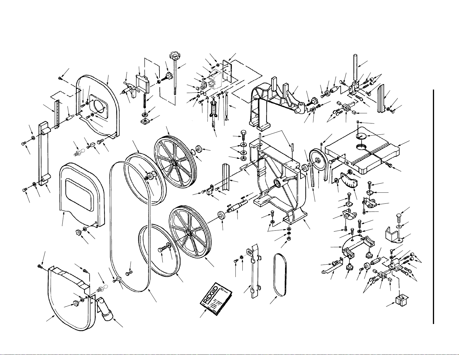
Parts List For RIDGID 14-inch Band Saw
Model No. BS14000
Figure 1
40
103
55
59
51
54
53
58
104
62
14
107
56
57
61
43
63
13
109
108
93
96
69
71
97
67
98
72
94
68
63
99
105
60
70
95
101
100
103
60
103
60
102
34
103
106
66
67
65
68
42
30
52
Repair Parts
7
45
3
17
46
4
9
8
15
10
11
12
13
15
26
27
24
13
14
23
31
32
33
34
35
10
9
6
6
21
22
25
28
29
30
5
37
36
6
5
4
1
20
50
3
2
18
17
51
64
19
44
48
47
41
40
27
28
39
16
49
13
25
26
43
38
80
111
79
Page 3

Parts List For RIDGID 14 Inch Band Saw
Model No. BS14000 Figure 1 - Drive Assembly Parts
Always Order By Part Number - Not By Key Number
Key
No.
10
11
12
13
14
15
16
17
18
19
20
21
22
23
24
25
26
27
28
29
30
31
32
33
34
35
36
37
38
39
40
41
42
43
44
45
46
47
48
49
50
51
52
53
54
55
56
* Standard hardware item. May be purchased locally.
Part No. Description
823545-1
1
826533
2
823746
3
820722-10
4
823574
5
823744-3
6
823575-2
7
823601
8
823954
9
823573
820249-4
823596
813307-3
823572
823745
823744-2
823743
823742
813249-76
823580
823559-1
823579
823769
823565
823586
823768
816755-10
823588
826538
823750-1
823779
826532
826626
813313-5
823587
818470-5
826664
817393-5
823585
817391-1
816782
817530
823741
821732-1
823756
*
*
*
*
*
*
*
*
*
*
*
Frame Upper Arm
Knob
Screw Pan Hd. Lock M6 x 1-12
Bearing Ball
Sleeve Upper Spacing
Screw Thumb M6-16
Post G uide
Bracket Support Post
Screw Soc Set M8 x 1.25-40
Nut Micro-Adjust
Screw hex Hd. M6 x 1.0-16
Guard Blade Upper
Washer M6
Screw Hex Hd. M6 x 1.0-10
Block Guide
Bracket Support Upper
Screw Thumb M6-12
Screw Soc. Cup M10 x 1.5-10
Spring
Ball Steel
Pin Spring
Insert Table
Table
Pin table
Screw Hex Hd. M10 x 1.5-55
Clamp Trunnion Shoe
Trunnion
Screw Hex Washer hd. M6 x 1-12
Screw Hex Hd. M8 x 1.25-80
Nut Hex M8
Screw Pan Cross M5 x 0.8-9
Lockwasher M5.5
Guard Blade Lower
Screw Hex Hd. M6 x 1.0-20
Bracket Lower Support Post
Guard Lower Wheel Blade
Bracket Support Lower
Knob Locking
Pointer
Screw Pan Hd. M5 x 0.8-6
Bracket Trunnion Support
Lockwasher M8
Screw Hex Hd. M8 x 1.25-35
Screw Flat Hd. Cross M5 x 0.8-15
Scale Bevel
Nut Hex M5 x 0.8
Belt V A40
Pulley
Screw Soc Set M6 x 1.0-10
Ring Retaining
Bearing Ball
Pin
Screw Hex Hd. M16 x 2.0-55
Washer M16
Nut M16
Stud
Key
No.
57
58
59
60
61
62
63
64
65
66
67
68
69
70
71
72
73
74
75
76
77
78
79
80
81
82
83
84
85
86
87
88
89
90
91
92
93
94
95
96
97
98
99
100
101
102
103
104
105
106
107
108
109
110
111
† Stock Item - May be secured through the Hardware
Department of most Home Depot Stores.
Part No. Description
823598
818470-3
823555
813313
819188
823584
*
823554-1
823556
823762
823761
823550
823763
823595
†
823753
823751
823583
817357
823558
826634
826536
823771
823552-1
816069
823760
823600
823597
*
823758-8
824283
823569
826537
823570
826535
826534
826627
826630
823755
AC1000
826123
*
826394
*
823546
63418
823563-1
823543-1
826628
826629
827589
SP6174
Hinge Lower
Screw Flat Hd. M5 x 0.8-10
Brush Wheel
Screw Pan Hd. M5 x 0.8-12
Key 5mm x 20mm
Shaft Lower Wheel
Washer M8
Base
Wheel Lower
Bearing Ball
Ring Retaining
Wheel Upper
Nut Hex M12 x 1.25
Tire
Blade 3/8 x 93-1/2
Screw Hex Hd. LH M8 x 1.25-25
Bolt M10 x 1.5-15 (Special)
Catch Door
Screw Pan Hd. M4 x 16-8
Chute Dust
Cover Lower Wheel
Knob Catch
Screw Pan Hd. Lock M6 x 1-8
Cover Upper Front
Screw Pan Hd. Ty “AB” #6 x 5/8
Washer
Guard Blade Rear
Hinge Upper
Washer M5
Cover Upper Back
Shaft/Hinge Upper Wheel
Pin
Bracket Sliding
Nut Wing
Knob Lock
Knob Blade Adjusting
Spring Coil
Indicator
Nut Square
†Key, Switch
Switch Locking
Screw Pan Hd. #6-32 x 3/8
Box Switch
Lockwasher M5
Plate Switch Backing
Clamp Cord
Cord w/Plug
Cord Power
Belt Sanding
Platen Sanding
Stud Latch
Owners Manual
29
Page 4

Parts List For RIDGID 14 Inch Band Saws
Model No. BS14000
Figure 2
Repair Parts
30
21
22
16
20
28
27
24
23
5
4
26
25
19
18
8
9
15
7
13
1
2
6
7
3
8
8
10
9
17
11
7
13
11
18
14
15
10
16
29
30
8
12
Page 5

Repair Parts
Parts List For RIDGID 14 Inch Band Saw
Model No. BS14000
Figure 2 - Base Components
Always order by Part Number - Not by Key Number
Key
No.
1
2
3
4
5
6
7
8
9
10
11
12
13
14
15
* Standard hardware item. May be purchased locally.
Part No. Description
823592-1
826530
*
*
*
*
*
823773-1
823590-1
823776
*
803835-1
*
*
*
Cover Pulley
Hanger Blade
Screw Pan Hd M4 x 0.7-10
Nut Hex M4 x 0.7
Washer 4mm
Screw Pan Hd. M5 x 0.8-12
Washer M5
Leg
Stiffener Long
Bolt Carriage M8 x 1.25-16
Nut Hex 3/8-16
Foot Leveling
Nut Hex M5
Nut Hex M8
Lockwasher M8
Key
No.
16
17
18
19
20
21
22
23
24
25
26
27
28
29
30
Part No. Description
*
823593-1
823589-1
823774-1
823747
823562
*
819188
817391-1
823740
823576
823591-1
*
813317-6
813317-8
Washer M8
Plate Support
Stiffener Short
Stand Top
Grommet Rubber
Motor
Screw Hex Hd. M8 x 1.25-35
Key 5mm x 20mm
Screw Set M6 x 1.0-10
Pulley Motor
Pad
Cover Pulley Inner
Screw Pan Hd. M4 x 16-8
Wrench Hex “L” 3mm
Wrench Hex “L” 5mm
31
Page 6

General
WARNING: For your own safety, turn switch “Off” and remove plug from power source outlet before trouble
shooting your band saw.
Trouble Probable Cause Remedy
Blade does not run in the
approximate center of the
upper wheel.
Band Saw slows down when
cutting
Blades braking 1. Too much tension on
Blade dulls too quickly. 1. Blade guides set too close
Band saw vibrates. 1. Too much tension on
1. Not tracking properly. 1. Adjust tracking, see Assembly Section, “Adjusting
1. Belt too loose.
2. Cutting too small a radius.
3. Dul l blade.
4. Overloading motor.
blade.
2. Kink in blade caused cutting too small a radius or
turning the material too
fast when cutting.
to teeth.
2. Cutting incorrect material
motor belt
Blade Tracking” section.
1. Adjust belt tension, see “Assembly” section, “Mounting the Motor”.
2. Stop feeding, and back up the material slightly, until
the band saw speeds up.
3. Replace blade.
4. Slow down, trying to cut too fast.
1. Adjust tension. See “Getting to Know Your Band
Saw”.
2. Use correct cutting technique. See “Basic Saw Operation” section.
1. Adjust upper and lower blades guides. See “Assembly” section “Installing the blade”.
1. Adjust according to “Mounting the Motor” section.
Wiring Diagram
Power Cord
To Switch
Black
Green
Switch
Switch
Green
WhiteWhite
Black
Motor
Motor
White
Green
Black
Pow er Co r d
Switch To Motor
Lead
Motor
Lead
Motor
27
 Loading...