

RIDGID 915 Operator's Manual
In Place
Roll Groover
OPERATOR’S
MANUAL
915
WARNING!
Read this Operator’s Manual
carefully before using this
tool. Failure to understand
and follow the contents of this
manual may result in serious
personal injury.
99 Washington Street
Melrose, MA 02176
Phone 781-665-1400
Toll Free 1-800-517-8431
Visit us at www.TestEquipmentDepot.com

915 In Place Roll Groover
manufacturer for your model. Ac cessories that may
be suitable for one tool may become hazardous when
used on another tool.
• Keep handles dry and clean; free from oil and
grease. Allows for better control of the tool.
Service
• Tool service must be performed only by qualified
repair personnel. Service or maintenance performed
by unqualified repair personnel could result in injury.
• When servicing a tool, use only identical replace-
ment parts. Follow instructions in the Maintenance
Section of this manual. Use of unauthorized parts or
failure to follow maintenance instructions may create a
risk of injury.
Specific Safety Information
WARNING
SAVE THESE INSTRUCTIONS!
Ridge Tool Company
2
General Safety Information
WARNING! Read and understand all instructions. Failure
to follow all instructions listed below may
result in serious personal injury.
SAVE THESE INSTRUCTIONS!
Work Area Safety
• Keep your work area clean and well lit. Cluttered
benches and dark areas invite accidents.
• Keep bystanders, children, and visitors away while
operating a tool. Distractions can cause you to lose
control.
• Keep floors dry and free of slippery materials
such as oil. Slippery floors invite accidents.
Personal Safety
• Stay alert, watch what you are doing and use common sense when operating a tool. Do not use tool
while tired or under the influence of drugs, alcohol,
or medications. A moment of inattention while oper-
ating tools may result in serious personal injury.
• Dress properly. Do not wear loose clothing or
jewelry. Contain long hair. Keep your hair, clothing,
and gloves away from moving parts. Loose clothes,
jewelry, or long hair can be caught in moving parts.
• Do not overreach. Keep proper footing and bal-
ance at all times. Proper footing and balance enables
better control of the tool in unexpected situations.
• Use safety equipment. Always wear eye protection.
Dust mask, non-skid safety shoes, hard hat, or hearing
protection must be used for appropriate conditions.
Tool Use and Care
• Do not force tool. Use the correct tool for your
application. The correct tool will do the job better
and safer at the rate for which it is designed.
• Store idle tools out of the reach of children and
other untrained persons. Tools are dangerous in
the hands of untrained users.
• Check for misalignment or binding of moving
parts, breakage of parts, and any other condition
that may affect the tool's operation. If damaged,
have the tool serviced before using. Many acci-
dents are caused by poorly maintained tools.
• Use only accessories that are recommended by the
Read this operator’s manual carefully before using
t
he 915 Roll Groover. Failure to understand and
follow the contents of this manual may result in
serious personal injury.
Roll Groover Safety
• Keep fingers away from rolls when grooving
pipe. Keep Sleeves and jackets buttoned. They
can become pinched resulting in serious injury.
• Do not wear loose fitting gloves. Can become
caught in rolls resulting in serious injury.
• Handle pipe carefully and have all burrs removed
from ends. Eliminates the risk of cuts to fingers and
hands.
• When working overhead, all personnel should
wear hard hats and be clear of the area below.
Prevents serious injuries if roll groover or workpiece
falls.
• Groover is designed to manually roll groove pipe
and tubing. Other uses may result in injury.
• Do not use power activated devices to aid in rotat-
ing the groover. Using a tool in a manner not intended can result in injury.
Ridge Tool Company
3
Description, Specifications
and Equipment
Description
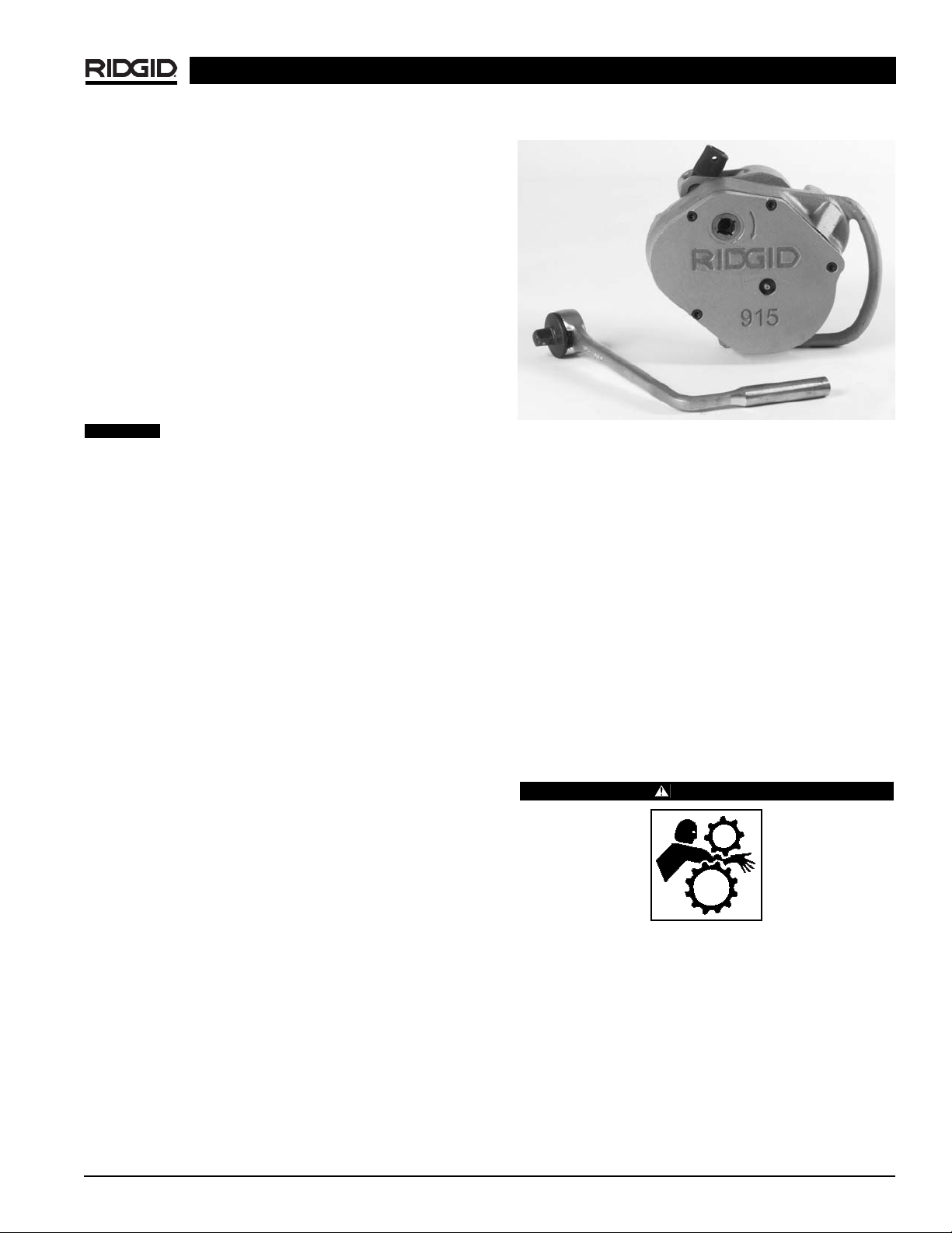
The RIDGID No. 915 Roll Groover is designed to manually form standard roll grooves on pipe or copper tube
that is installed. The 915 is lightweight, only 23 lbs., and
capable of grooving steel, stainless steel, PVC and aluminum pipe from 11/4″ to 12″ and 2″ to 8″ copper tube
(Type K, L, M, and DWV). The 1/2″ hand ratchet rotates
a feed screw that advances a groove roll into the
pipe/tube to form a groove that meets specifications
required for mechanical coupling systems, and also
drives the 915 around the pipe.
When properly used, the Model 915 Roll
Groover makes grooves that are dimensionally within the
specifications of AWWA C606-87. Selection of appropriate materials and joining methods is the responsibility of the system designer and/or installer. Before any
installation is attempted, careful evaluation of the specific
service environment, including chemical environment
and service temperature, should be completed.
Specifications
Capacity ........................Standard 2″ – 6″ Schedule 10
and 2″ – 31/2″ Schedule 40
Steel Pipe
Depth Adjustment..........Feed Screw with 1/2″ Female
Drive
Actuation........................Feed Screw with 1/2″ Ratchet
Wrench
Weight............................23 lbs.
With Roll Changes:
• 2″ – 8″ Copper Tube,
Type K, L, M, DWV
• 1
1
/4″ and 11/2Schedule 10 and 40 Steel/Stainless
Steel Pipe
• 4″ – 6″ Schedule 40
Steel/Stainless Steel Pipe
• 8″ – 12″ Schedule 10
Steel/Stainless Steel Pipe
(See Table II for Wall Thickness.)
Standard Equipment
Model 915......................Groove set for
2″ – 6″ Schedule 10 and
2″ – 31/2″ Schedule 40
1
/2″ Drive Ratchet w/button
release
Figure 1 – 915 Roll Groover
Accessories
• Groove set for 11/4″ to 11/2″ Schedule 10 & 40 pipe.
• Groove set for 4″ to 6″ Schedule 40 pipe.
• Groove set for 8″ – 12″ Schedule 10.
• Copper groove set for 2″ to 8″ Copper Tube
Type K, L, M, DWV.
• Carrying case for 915 and roll sets.
The 915 Roll Groover is a portable unit designed for occasional use on the jobsite and should not be used for high
volume work.
Roll Groover Inspection
WARNING
To prevent serious injury, inspect your Roll
Groover. The following inspection procedures
should be performed on a daily basis:
1. Inspect the Roll Groover for any broken, missing,
misarranged or binding parts as well as any other
conditions which may affect the safe and normal
operation of this equipment. If any of these conditions
are present, do not use the Roll Groover until any
problem has been repaired.
2. Lubricate the Roll Groover if necessary according
to the Maintenance Instructions.
915 In Place Roll Groover
CAUTION
Ridge Tool Company
4
3. Use groover rolls and accessories that are designed for
your Roll Groover and meet the needs of your application. The correct groover tools and accessories
allow you to do the job successfully and safely.
Accessories designed for use with other equipment
may be hazardous when used with this Roll Groover.
4. Clean any oil, grease or dirt from all handles and
controls. This reduces the risk of injury due to a tool or
control slipping from your grip.
5. Inspect the groove rolls to insure they are not damaged or worn. Worn groover rolls can lead to slippage
and poor quality grooves.
Roll Groover and
Work Area Set-Up
WARNING
To prevent serious injury,
proper set-up of the Groover and work area is
required. The following procedures should be followed to set-up the machine:
1. Insure work area has adequate lighting.
2. Clean up the work area prior to setting up any equipment. Always wipe up any oil that may be present.
3. Check the groove and drive rolls to insure they are the
correct size.
Use of roll sets on both carbon and stainless
steel pipe can lead to contamination of the stainless steel
material. This contamination could cause corrosion and
premature pipe failure. To prevent ferrous contamination, use roll sets dedicated for stainless steel grooving.
4. Make sure pipe/tube is secured and not free to rotate
prior to roll grooving.
• If pipe is not installed, use a bench vise or tristand
vise to secure the pipe. Pipe supports must be used
if pipe is greater than 36″ in length.
Failure to properly support the pipe can
result in the pipe falling.
Place vise and stands on a flat level surface. Be
sure the pipe, vise and stands are stable.
• If the pipe/tube is installed, care must be taken to
prevent pipe rotation or movement. Make sure that
the added weight and force required of the 915
can be supported by the pipe hangers and clamps.
Operating the 915 Roll Groover
WARNING
Do not wear loose clothing when operating a Roll
Groover. Keep sleeves and jackets buttoned.
Always wear eye protection to protect eyes from
dirt and other foreign objects. When working overhead, wear a hard hat and keep personnel clear of
area.
Keep hands away from grooving rolls. Do not wear
loose fitting gloves when operating groovers. Use
pipe stands to support pipe when using a pipe vise.
Unit to be hand driven only. Do not power with drill
or other types of units.
Pipe Preparation
1. Make sure pipe/tube end is cut square and free of
burrs. Do not attempt to groove pipe that has been cut
with a torch.
2. Pipe/tube out-of-roundness must not exceed the
total O.D. tolerances listed in the dimension specification
(Table 1).
NOTE! Determine out-of-roundness by measuring max-
imum and minimum outside dimensions at 90
degree increments. Compare minimum and
maximum numbers with pipe diameter column
in
Table 1
.
3. All internal or external weld beads, flash or seams
must be ground flush at least 2″ back from the pipe
end.
IMPORTANT! Do not grind flats on the pipe outside wall
where the coupling gasket seals (gasket
seat area).
4. The 915 Roll Groover will orbit around the pipe/tube.
Care must be taken that adequate space is provided
completely around material.
NOTE! The RIDGID 915 can roll groove pipe/tube with-
in 3
1
/2″ of a wall, ceiling or any other obstruction.
915 In Place Roll Groover
CAUTION
WARNING
Ridge Tool Company
5
915 Roll Groover Set-up
IMPORTANT! To confirm the proper groove depth, test
grooves should be performed and checked
with a Pi tape.
1. At a bench or on the ground, rotate the feed screw
counter clockwise to “open” the groove roll from
the drive roll
(Figure 2)
.
Figure 2 – “Open” Groove Roll from Drive Roll.
NOTE! Ensure that groove set specifications matches
pipe/tube capacity to be grooved. See drive roll
for capacity.
IMPORTANT! Do not attempt to groove copper tube with
the steel groove set. Also do not attempt to
groove steel with copper groove rolls.
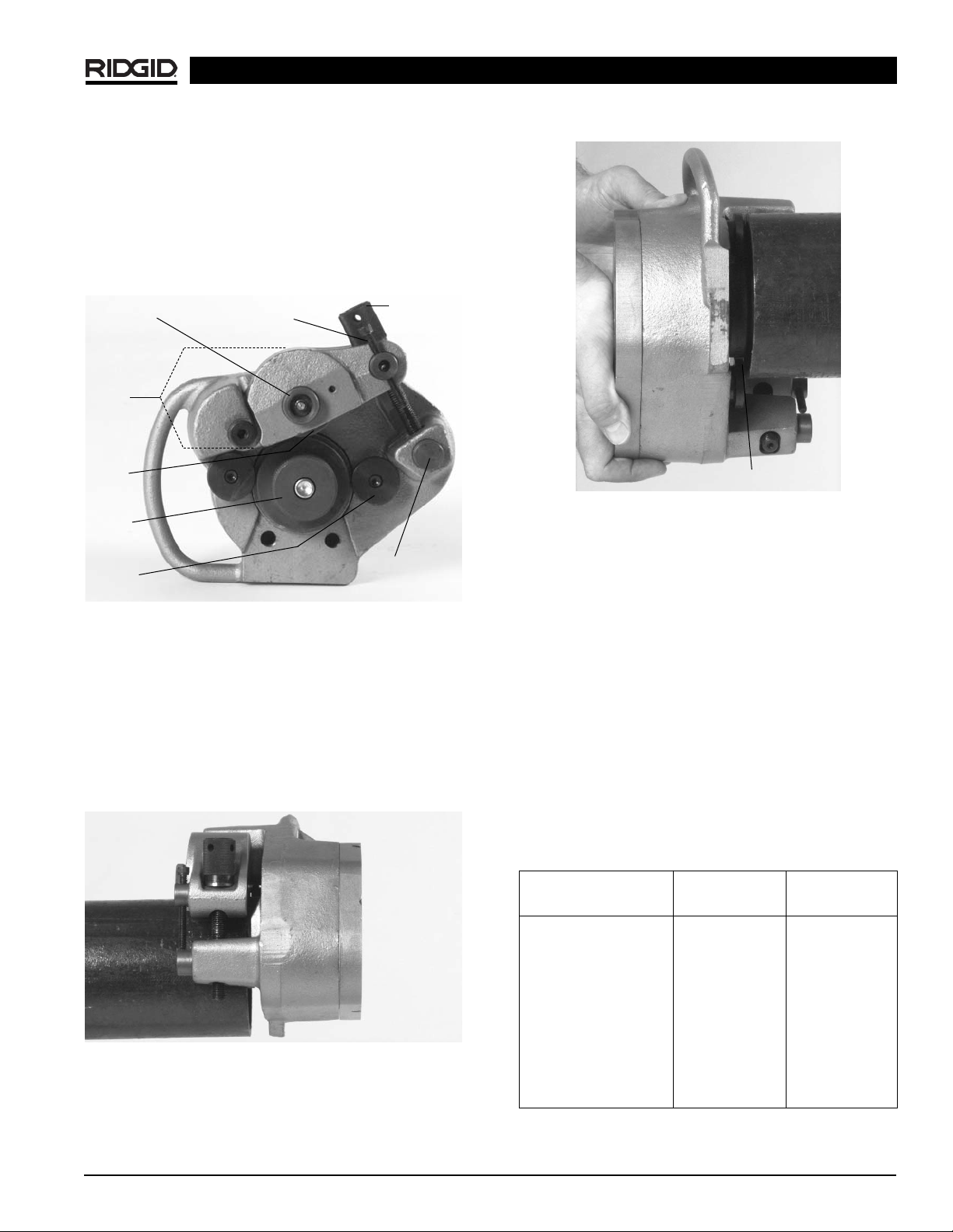
2. Place 915 onto pipe/tube with feedscrew accessible
(Figure 3)
.
Figure 3 – Placing Groover on Pipe
3. Push 915 into pipe/tube until fully engaged. End of
pipe should contact the drive roll flange
(Figure 4)
.
Figure 4 – Pipe Contact with Drive Roll Flange
4. Rotate the feed screw clockwise by hand until tight.
915 should now be held in position on the pipe/tube.
Adjusting for Groove Depth
NOTE! The groove depth must be adjusted for each
pipe/tube diameter and wall thickness.
1. With feedscrew handtight, run depth adjustment
screw down until it touches the pivot nut.
2. Back the depth adjustment screw off the number of
turns indicated in
Chart 1 (For Steel/Stainless Steel,
For Copper See Chart 2. These are approximate settings only).
NOTE! The distance between the depth adjustment
screw and the pivot nut equals roll groove depth.
Adjustments up or down, with test grooves, will
ensure proper groove depths for couplings.
Chart 1 – Depth Adjustment for Steel/Stainless Steel
915 In Place Roll Groover
Groove Roll
Shaft
Feedscrew
Reaction
Arm
Groove
Roll
Drive
Roll
Stabilizer
Pads
Pivot
Nut
Depth
Adjustment
Screw
Drive Roll Flange
Steel/Stainless Steel Sch. 10 Sch. 40
Pipe Diameter Turns Turns
11/4″ 33/
4
4
11/2″ 33/
4
4
2″ 33/
4
4
21/2″ 43/
8
53/
8
3″ 43/
8
55/
8
4″ 45/
8
67/
8
6″ 57
1
/
2
8″ 6N/A
10″ 61/
4
N/A
12″ 71/
2
N/A
 Loading...