

RIDGID 603, 604, 606, 605, 608 Instruction Sheet
...
600 Hand Tube Bender Instruction Sheet
WARNING
Read these instructions and the warnings and
instructions for all equipment being used before
using to reduce the risk of serious personal injury.
• Always use safety glasses to reduce the risk of
eye injury.
• Do not use handle extensions (such as a piece
of pipe). Han dle extensions can slip or come off and increase
the risk of serious injury.
Test
Equipment Depot - 800.517.8431
99 Washington Street, Melrose, MA 02176
TestEquipmentDepot.com
®
The RIDGID
materials such as copper, steel, stainless steel and other hard metal
tube to a maximum of 180°. Built-in rollers and a heavy-duty handle
design combine to produce high quality bends with greatly reduced
effort when compared to conventional benders.
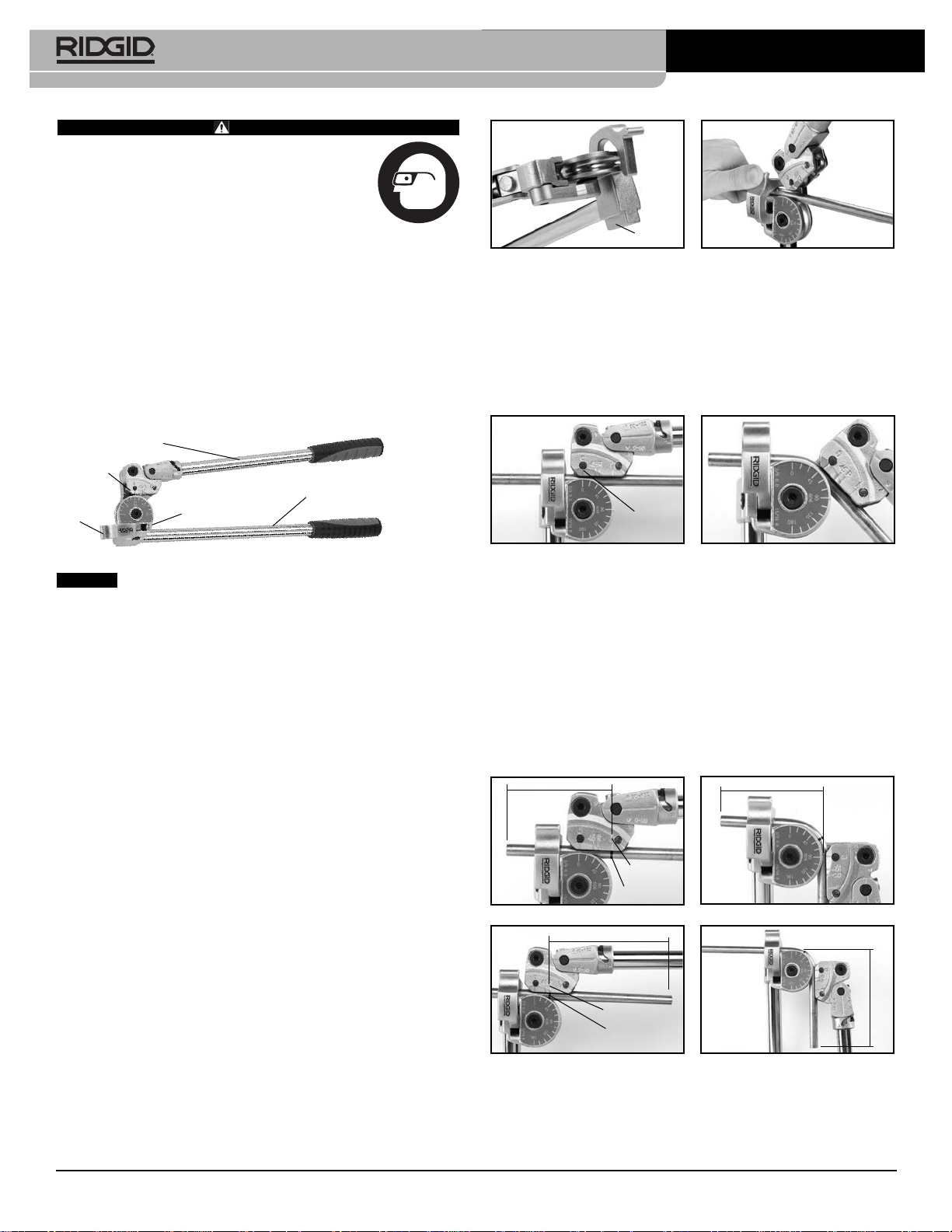
Carriage Handle
Carriage
Tube
Latch
600 series lever benders are designed to easily bend
Form Handle
Form
Grip In
Vise
Figure 2 – Vise Mounting Point Figure 3
2. Move Carriage Handle and Tube Latch away from Form.
3. Position tubing in Form groove and secure tubing in Form with
Latch (Figure 3).
4. Lower Carriage Handle until the “0” Line on the Carriage aligns with
the 0° designation on the Form (Figure 4).
5. Rotate the Carriage Handle around the Form until the “0” Line on the
Carriage aligns with the desired degree of bend on the Form (Figure
5).
0 Line
Figure 1 – 600 Series Bender
NOTICE
Selection of appropriate materials and installation, joining
and forming methods is the responsibility of the system designer and/or
installer. Selection of improper materials and methods could cause system failure.
Stainless steel and other corrosion resistant materials can be contaminated during installation, joining and forming. This contamination could
cause corrosion and premature failure. Careful evaluation of materials
and methods for the specific service conditions, including chemical and
temperature, should be completed before any installation is attempted.
Inspection/Maintenance
The bender should be inspected before each use for wear or damage
that could affect safe use. Clean as needed to aid inspection and to prevent handles and controls from slipping from your grip during use.
Make sure the bender is complete and properly assembled. If any problems are found, do not use until the problems are corrected. Lubricate
all moving parts/joints as needed with a light lubricating oil, and wipe
any excess oil from the bender.
Operation
The 600 Series Lever Benders can be used either hand held or with the
bender mounted in a vise. Vise mounting is especially useful when
bending hard or thick walled materials.
Spring Back
All tubing will exhibit spring back after a bend is completed. Softer tubing, such as copper, will have less spring back than harder tubing, such
as stainless steel. Experience will help you predict the amount of spring
back. Depending on tubing material and hardness, expect to overbend
approximately 1° to 3° to compensate for spring back.
General Operating Instruction
1. Grasp bender by the Form Handle or mount the bender in vise.
(Figure 2).
Figure 4 Figure 5
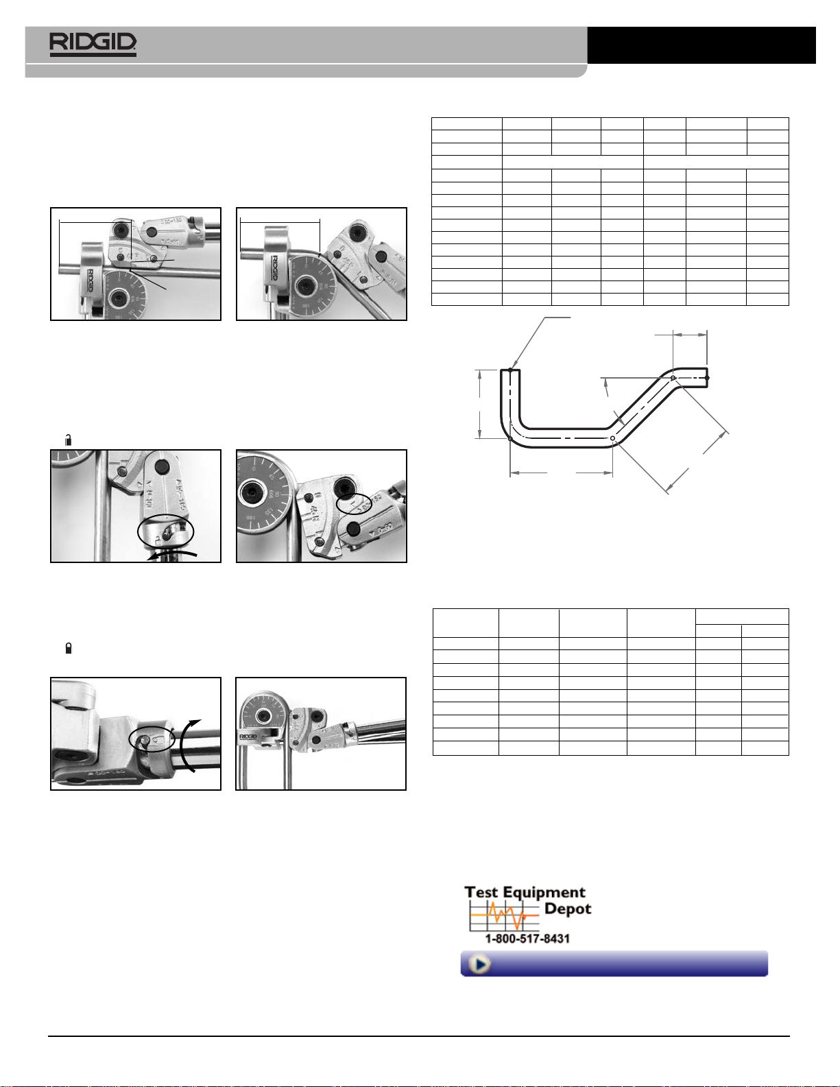
Measured Bends Relative to Other
Features (Tube ends, Bends, etc.)
For 90° Bends:
• Mark the tube at the desired distance (X) from the feature (end of
tube, bend, etc.). The center of the leg of the bend will be this distance from the feature.
• Place the tube in the bender as described in Steps 1-5 above.
• If the feature is to the LEFT of the mark (see Figure 6 – Before),
align the mark on the tube with the “L” line on the Carriage.
• If the feature is to the RIGHT of the mark (see Figure 8 – Before),
align the mark on the tube with the “R” line on the Carriage.
X
L Line
Mark On
Tube
Figure 6 – Before Figure 7 – After
X
R Line
Mark On
Tube
Figure 8 – Before Figure 9 – After
• With the mark on the tube appropriately aligned, move the Carriage
so that the “0” Line aligns with the 90 degree line on the Form. (See
Figures 7 and 9 – After).
X
X
Printed 12/15
EC38632
The Emerson logo and RIDGID logo are registered trademarks of Emerson Electric Co. or RIDGID, Inc. in the U.S. and other countries.
©2011, 2015, RIDGID, Inc.
All other trademarks belong to their respective holders.
999-999-403.10
REV. C
600 Hand Tube Bender Instruction Sheet
1.50
45°
2.00
3.00
1 .00
REFERENCE MARK
For 45° Bends:
• Mark the tube at the desired distance (X) from the feature (end of
tube, bend, etc.). The center of the arc segment will be this distance
from the feature.
• Place the tube in the bender as described in Steps 1-5 above.
• Align the mark on the tube with the 45° line on the Carriage (see
Figure 10).
X
45 Line
Mark On
Tube
X
Figure 10 – Before Figure 11 – After
• With the mark on the tube appropriately aligned, move the Carriage
Handle so that the “0” Line aligns with the 45 degree line on the Form.
Making Bends 90° to 180°
Follow the steps 1-5 for making 90° bends.
1. When the “0” Line on the Carriage reaches the 90° mark on the
Form, turn the carriage handle so that the pin moves the “unlock”
Position (Figure 12).
Figure 12 – UNLOCK Figure 13 – Rotate Handle
2. Rotate the handle around the Carriage until the 90~180° triangle
mark on the Handle aligns with the triangle mark on the Carriage
(Figure 13).
3. Turn the Carriage Handle so that the pin moves toward the “lock”
position. Make sure the Handle is secure to the Carriage. (Figure
14).
Figure 14 – LOCK Figure 15
4. Swing the Carriage Handle around the Form until the “0” Line on
the Carriage aligns with the desired bend angle (Figure 15). The
Handles will not cross.
Bend Adjustment Chart
Model No. 603/604 605/606 608 606M 608M/610M 612M
Tube OD
Bend Radius
Degree Bend Adjustment (Inches) Bend Adjustment (mm)
90 0.27 0.40 0.65 6.88 10.32 16.34
85 0.22 0.33 0.52 5.59 8.38 13.27
80 0.18 0.26 0.42 4.52 6.78 10.73
75 0.14 0.21 0.34 3.61 5.42 8.58
70 0.11 0.17 0.27 2.86 4.29 6.80
65 0.09 0.13 0.21 2.24 3.36 5.32
60 0.07 0.10 0.16 1.72 2.58 4.08
55 0.05 0.08 0.12 1.32 1.98 3.14
50 0.04 0.06 0.09 0.96 1.44 2.27
45 0.03 0.04 0.06 0.69 1.03 1.63
40 0.02 0.03 0.05 0.48 0.72 1.15
EXAMPLE:
TUBE SIZE = 3/8" Adjustment for 90° bend = 0.40 (x 1)
BEND RADIUS = 15/16" Adjustment for 45° bend = 0.04 (x 2)
ACTUAL TUBE = Sum of Centerline Dimensions - Adjustments for Bends
LENGTH REQUIRED = 2.00 + 3.00 + 1.50 + 1.00 - 0.40 - 0.04 - 0.04 =
3
/16", 1/4"5/16, 3/
5
8
/
8
15
16
/
(Values Found In Adjustment Chart)
= 7.02"
1
2
/
6mm 8mm, 10mm 12mm
11/216mm 24mm 38mm
Bender Specification
Catalog Model Capacity Bend Weight
No. No. (O.D.) Radius lbs. kgs.
38028 603
38033 604
38038 605
38043 606
38048 608
3
/16"
1
/4"
5
/16"
3
/8"
1
/2"1
5
/8" 1.68 0.76
5
/8" 1.68 0.76
15
/16" 4.1 1.84
15
/16" 4.1 1.84
1
/2" 6.1 2.76
38053 606M 6mm 16mm 1.68 0.76
38038 608M 8mm 24mm 4.1 1.84
38058 610M 10mm 24mm 4.1 1.84
38063 612M 12mm 38mm 6.1 2.76
Supporting Products Recommendation
Cat. No. 31803 65S Quick-Acting Tubing Cutter
Cat. No. 29963 35S Stainless Steel Tubing Cutter
Cat. No. 29993 227S Stainless Steel Inner-Outer Reamer
Cat. No. 29983 223S Stainless Steel Inner-Outer Reamer
Adjustment (Gain) Calculations
When determining tube bend locations, adjustment factors must be
considered to achieve proper layout. Adjustment (Gain) is the difference
in the length of tubing used in a radiused bend compared to the length
of tubing required in a sharp bend, when measured from one end to
another.
The distance around a radiused bend is always less than a sharp bend.
The adjustment factor is determined by the radius of the tube bender
and the number of degrees of the bend. See the following chart for ad justment factors. Adjustment factors are subtracted from the center line
distances (see the example).
99 Washington Street
Melrose, MA 02176
Phone 781-665-1400
Toll Free 1-800-517-8431
Visit us at www.TestEquipmentDepot.com
 Loading...