

RIDGID 300 Compact, 1233 User Manual

Threading MachinesManual
300 Compact/1233
No Foot Switch
300 Compact
1233
• Français – 21
• Castellano – pág. 43
• CN – pág. 65

300 Compact/1233 Threading Machines
Table of Contents
Recording Form For Machine Serial Number..................................................................................................................................1
Safety Symbols ..................................................................................................................................................................................2
General Power Tool Safety Warnings
Work Area Safety ............................................................................................................................................................................2
Electrical Safety ..............................................................................................................................................................................2
Personal Safety ..............................................................................................................................................................................3
Tool Use And Care..........................................................................................................................................................................3
Service ............................................................................................................................................................................................3
Specific Safety Information
Safety Instructions for Transportable Threading Machines ............................................................................................................4
Description, Specifications And Standard Equipment
Description ......................................................................................................................................................................................4
Specifications ..................................................................................................................................................................................5
Standard Equipment ......................................................................................................................................................................6
Machine Assembly
Mounting on Stands ........................................................................................................................................................................6
Mounting on Bench ........................................................................................................................................................................6
Mounting on Pipe Legs ..................................................................................................................................................................6
Pre-Operation Inspection ..................................................................................................................................................................7
Machine and Work Area Set-Up........................................................................................................................................................7
Die Head Set-Up and Use
Removing/Installing Die Head ........................................................................................................................................................9
Quick-Opening Die Heads ..............................................................................................................................................................9
Inserting/Changing the Dies ........................................................................................................................................................9
Adjusting Thread Size ..................................................................................................................................................................9
Opening the Die Head at the End of the Thread..........................................................................................................................9
Self-Opening Die Heads ..............................................................................................................................................................10
Inserting/Changing the Dies ......................................................................................................................................................10
Adjusting Thread Size ................................................................................................................................................................10
Trigger Slide Adjustment............................................................................................................................................................10
Opening the Die Head at the End of the Thread........................................................................................................................10
Receding Self-Opening Die Heads ..............................................................................................................................................11
Inserting/Changing the Dies ......................................................................................................................................................11
Adjusting Thread Size ................................................................................................................................................................11
Adjusting Thread Length ............................................................................................................................................................11
Preparing the Die Head to Thread ............................................................................................................................................12
Opening the Die Head at the End of the Thread........................................................................................................................12
Operating Instructions
Cutting ..........................................................................................................................................................................................13
Reaming........................................................................................................................................................................................13
Threading Pipe..............................................................................................................................................................................14
Threading Bar Stock/Bolt Threading ............................................................................................................................................14
Left Hand Threading ....................................................................................................................................................................14
Removing Pipe from the Machine ................................................................................................................................................15
Inspecting Threads........................................................................................................................................................................15
Preparing Machine for Transport ..................................................................................................................................................16
Maintenance Instructions
Cleaning ........................................................................................................................................................................................16
Lubrication ....................................................................................................................................................................................16
Oil System Maintenance ..............................................................................................................................................................16
Replacing Cutter Wheel ................................................................................................................................................................17
Replacing Jaw Inserts ..................................................................................................................................................................17
Replacing Carbon Brushes ..........................................................................................................................................................17
Optional Equipment ........................................................................................................................................................................18
Thread Cutting Oil Information ......................................................................................................................................................18
Machine Storage ..............................................................................................................................................................................18
Service And Repair ..........................................................................................................................................................................18
Disposal ............................................................................................................................................................................................18
Troubleshooting ..............................................................................................................................................................................19
Lifetime Warranty ..............................................................................................................................................................Back Cover
*Original Instructions - English
ii

Threading Machines
300 Compact/1233
WARNING!
Read this Operator’s Manual
carefully before using this tool.
Failure to understand and follow the contents of this manual
may result in electrical shock,
re and/or serious personal
injury.
300 Compact
1233
300 Compact/1233 Threading Machines
Record Serial Number below and retain product serial number which is located on name plate.
Serial
No.
300 Compact/1233 Threading Machines
Safety Symbols
In this operator’s manual and on the product, safety symbols and signal words are used to communicate important safety information. This section is provided to improve understanding of these signal words and symbols.
This is the safety alert symbol. It is used to alert you to potential personal injury hazards. Obey all safety messages that follow this
symbol to avoid possible injury or death.
DANGER
WARNING
CAUTION
NOTICE
NOTICE indicates information that relates to the protection of property.
This symbol means read the operator’s manual carefully before using the equipment. The operator’s manual contains important information on the safe and proper operation of the equipment.
This symbol means always wear safety glasses with side shields or goggles when handling or using this equipment to reduce
the risk of eye injury.
This symbol indicates the risk of fingers, hands, clothes and other objects catching on or between gears or other rotating parts
and causing crushing injuries.
This symbol indicates the risk of fingers, legs, clothes and other objects catching and/or wrapping on rotating shafts causing
crushing or striking injuries.
This symbol indicates the risk of electrical shock.
This symbol indicates the risk of machine tipping, causing striking or crushing injuries.
This symbol means do not wear gloves while operating this machine to reduce the risk of entanglement.
DANGER indicates a hazardous situation which, if not avoided, will result in death or serious injury.
WARNING indicates a hazardous situation which, if not avoided, could result in death or serious injury.
CAUTION indicates a hazardous situation which, if not avoided, could result in minor or moderate injury.
General Power Tool Safety
Warnings
• Keep children and by-standers away while operating a power. Distractions can cause you to lose control.
WARNING
Read all safety warnings, instructions, illustrations and specifications provided with this power
tool. Failure to follow all instructions listed below
may result in electric shock, fire and/or serious
injury.
SAVE ALL WARNINGS AND INSTRUCTIONS
FOR FUTURE REFERENCE!
The term "power tool" in the warnings refers to your
mains-operated (corded) power tool or battery-operated
(cordless) power tool.
Work Area Safety
• Keep work area clean and well lit. Cluttered or dark
areas invite accidents.
• Do not operate power tools in explosive atmo-
spheres, such as in the presence of flammable
liquids, gases, or dust. Power tools create sparks
which may ignite the dust or fumes.
2
Electrical Safety
• Power tool plugs must match the outlet. Never
mod ify the plug in any way. Do not use any adapter
plugs with earthed (grounded) power tools. Unmodi -
fied plugs and matching outlets will reduce risk of electric shock.
• Avoid body contact with earthed or grounded sur-
faces such as pipes, radiators, ranges and refrigerators. There is an increased risk of electrical shock
if your body is earthed or grounded.
• Do not expose power tools to rain or wet condi-
tions. Water entering a power tool will increase the risk
of electrical shock.
• Do not abuse the cord. Never use the cord for
carrying, pulling or unplugging the power tool.
Keep cord away from heat, oil, sharp edges or
moving parts. Damaged or entangled cords increase
the risk of electric shock.

300 Compact/1233 Threading Machines
• When operating a power tool outdoors, use an
extension cord suitable for outdoor use. Use of a
cord suitable for outdoor use reduces the risk of electric shock.
• If operating a power tool in a damp location is
unavoidable, use a ground fault circuit interrupter
(GFCI) protected supply. Use of a GFCI reduces
the risk of electric shock.
Personal Safety
• Stay alert, watch what you are doing and use common sense when operating a power tool. Do not
use a power tool while you are tired or under the
influence of drugs, alcohol, or medication. A mo -
ment of inattention while operating power tools may
result in serious personal injury.
• Use personal protective equipment. Always wear
eye protection. Protective equipment such as dust
mask, non-skid safety shoes, hard hat, or hearing
protection used for appropriate conditions will reduce
personal injuries.
• Prevent unintentional starting. Ensure the switch
is in the OFF-position before connecting to power
source and/or battery pack, picking up or carrying
the tool. Carrying power tools with your finger on the
switch or energizing power tools that have the switch
ON invites accidents.
• Remove any adjusting key or wrench before turn-
ing the power tool ON. A wrench or a key left
attached to a rotating part of the power tool may result
in personal injury.
• Do not overreach. Keep proper footing and bal-
ance at all times. This enables better control of the
power tool in unexpected situations.
• Dress properly. Do not wear loose clothing or
jewelry. Keep your hair, and clothing away from
moving parts. Loose clothes, jewelry, or long hair
can be caught in moving parts.
for your application. The correct power tool will do the
job better and safer at the rate for which it is designed.
• Do not use power tool if the switch does not turn it
ON and OFF. Any power tool that cannot be controlled with the switch is dangerous and must be
repaired.
• Disconnect the plug from the power source and/or
the battery pack, if detachable, from the power
tool before making any adjustments, changing
accessories, or storing power tools. Such preven-
tive safety measures reduce the risk of starting the
power tool accidentally.
• Store idle power tools out of the reach of children
and do not allow persons unfamiliar with the
power tool or these instructions to operate the
tool. Power tools are dangerous in the hands of
untrained users.
• Maintain power tools and accessories. Check for
misalignment or binding of moving parts, breakage
of parts and any other condition that may affect the
power tool’s op er ation. If damaged, have the power
tool repaired before use. Many accidents are caused
by poorly maintained power tools.
• Keep cutting tools sharp and clean. Properly main-
tained cutting tools with sharp cutting edges are less
likely to bind and are easier to control.
• Keep handles and grasping surfaces dry, clean
and free from oil and grease. Slippery handles and
grasping surfaces do not allow for safe handling and
control of the tool in unexpected situations.
• Use the power tool, accessories and tool bits etc. in
accordance with these instructions, taking into
account the working conditions and the work to be
performed. The use of the power tool for operations dif-
ferent from those intended could result in a hazardous
situation.
Service
• If devices are provided for the connection of dust
extraction and collection facilities, ensure these are
connected and properly used. Use of dust collection
can reduce dust-related hazards.
• Do not let familiarity gained from frequent use of
tools allow you to become complacent and ignore
tool safety principles. A careless action can cause
severe injury within a fraction of a second.
Power Tool Use and Care
• Do not force power tool. Use the correct power tool
• Have your power tool serviced by a qualified repair
person using only identical replacement parts.
This will ensure that the safety of the power tool is
maintained.
Specific Safety Information
WARNING
This section contains important safety information
that is specific to these tools.
Read these precautions carefully before using the
3

300 Compact/1233 Threading Machines
300 Compact/1233 Threading Machines to reduce
the risk of electrical shock or other serious injury.
SAVE THESE INSTRUCTIONS!
Keep this manual with machine for use by the operator.
Safety Instructions for Transportable
Threading Machines
This threading machine is not equipped with a foot switch.
Foot switches are required by standards in certain markets, such as the United States, Canada, Australia, the
European Union, Russia, Turkey and Saudi Arabia. Do not
use machines without foot switches if standards require
them. Foot switches improve operational convenience
and reduce risk. When foot switches are required, they
should be hardwired to the machine.
• Keep floor dry and free of slippery materials such as
oil. Slippery floors invite accidents.
• Restrict access or barricade the area when work
piece extends beyond machine to provide a minimum of one meter clearance from the work piece.
Restricting access or barricading the work area around
the work piece will reduce the risk of entanglement.
• Do not wear gloves. Gloves may be entangled by the
rotating pipe or machine parts leading to personal
injury.
• Do not use for other purposes such as drilling
holes or turning winches. Other uses or modifying this
machine for other applications may increase the risk of
serious injury.
a complete stop before touching the pipe. This
practice will reduce the chance of entanglement in
rotating parts.
• Do not use this machine to install or remove (make
or break) fittings, it is not an intended use of the
machine. This practice could lead to trapping, entan-
glement and loss of control.
• Keep covers in place. Do not operate the machine
with covers removed. Exposing moving parts increases the probability of entanglement.
• One person must control the work process and
ma chine operation. Only the operator should be in the
work area when the machine is running. This helps
reduce the risk of injury.
• Never reach into the machine front chuck or rear
centering head. This will reduce the risk of entanglement.
• Read and understand these instructions and the
instructions and warnings for all equipment and
materials being used before operating this tool to
reduce the risk of serious personal injury.
If you have any question concerning this RIDGID®product:
– Contact your local RIDGID®distributor.
– Visit www.RIDGID.com to find your local RIDGID
contact point.
– Contact Ridge Tool Technical Service Department
at rtctechservices@emerson.com, or in the U.S. and
Cana da call (800) 519-3456.
• This machine is used to cut, ream and thread pipe
per these instructions. Do not use with equipment
which require the use of a foot switch, such as geared
threaders or roll groovers.
• Secure machine to bench or stand. Support long
heavy pipe with pipe supports. This practice will
prevent tipping.
• Operate the machine from the operator control
(switch) side. Be sure you can control the switch at
all times. Operating the machine from the switch side
improves control and eliminates need to reach over the
machine. Switch control helps to reduce the risk of serious injury.
• Do not leave machine running unattended. Place
switch in OFF position when plugging in and not in use
to reduce the risk of entanglement.
• Keep hands away from rotating pipe and fittings.
Stop the machine before wiping pipe threads or
screwing on fittings. Allow the machine to come to
4
Description, Specifications
And Standard Equipment
Description
The RIDGID®Model 300 Compact and 1233 Threading
Machines are electric motor-driven machines that center
and chuck pipe, conduit and bolt stock and rotates it while
cutting, reaming and threading operations are performed.
Threading dies are mounted in a variety of available die
heads. An integral oiling system with adjustable flow rate
is provided to flood the work with thread cutting oil during
the threading operation.

300 Compact/1233 Threading Machines
Rear
Centering
Device
Motor
Cover
Cutter
Chuck Jaw
Handwheel
REV/OFF/FWD
(2/0/1)
Switch
Warning
Hand
Hold
Label
Chip Tray
Quick Opening
Die Head
Carriage
Handwheel
Figure 1 – 300 Compact Threading Machine
Specifications
Reamer
Carriage
Front
Hand
Hold
Oil
Drain
Rear
Centering
Device
Motor
Cover
(2/0/1)
Switch
Warning
Label
Chuck Jaw
Handwheel
Chip
Tray
REV/OFF/FWD
Figure 2 – 1233 Threading Machine
Carriage
No. 763
Cutter
Die
Head
No. 743
Reamer
Drain
Carriage
Handwheel
Oil
Parameter 300 Compact Threading Machine 1233 Threading Machine
Pipe Threading Capacity
1
/8to 2 inch (3 to 50 mm)
1
/8to 3 inch (3 to 80 mm)
(Nominal Pipe Size)
Bolt Threading Capacity
1
/4to 2 inch (6 to 50 mm)
3
/8to 2 inch (9,5 to 50 mm)
(Actual Stock Diameter)
Yes No
LH Threads (units with REV only)
Rated Motor Power (HP)
1
/2HP (0.37 kW)
1
/2HP (0.37 kW)
Motor Type Universal Motor, Single Phase Universal Motor, Single Phase
Electrical Information 36 RPM 52 RPM 115 V, 50/60 Hz, 15 AMP
115 V, 50/60 Hz, 12 AMP 115 V, 50/60 Hz, 18 AMP 230 V, 50/60 Hz, 8 AMP
230 V, 50/60 Hz, 8 AMP
1700 W 2100 W 1700 W
Operating Speed 36 RPM (52 RPM version available) 36 RPM
Rotary Type REV/OFF/FWD (2/0/1) switch Rotary Type REV/OFF/FWD (2/0/1) switch
Controls Some units use an OFF/ON Rocker Some units use an OFF/ON Rocker
Switch in place of the Rotary Switch. Switch in place of the Rotary Switch.
Front Chuck Hammer-Type with replaceable Hammer-Type with replaceable
Rocker-Action Jaw Inserts Rocker-Action Jaw Inserts
Rear Centering Device Scroll operated, rotates with Chuck Scroll operated, rotates with Chuck
Die Heads See RIDGID Catalog for available Die Heads See RIDGID Catalog for available Die Heads
1
Cutter Model 360,
/8" - 2" Full Floating, Model 763, 1⁄4" - 3",
Self Centering Cutter Self Centering Cutter
1
Reamer Model 344,
/8" - 2" Reamer Model 743, 1⁄4" - 3", 5-Fluted Reamer
Oil System Reservoir Capacity 3.2 qt (3 l), Reservoir Capacity 3.2 qt (3 l),
with integrated Gerotor Pump, with integrated Gerotor Pump,
adjustable flow rate adjustable flow rate
Weight (Unit with Oil and a Die Head) 147 lb (67 kg) 165 lb (75 kg)
5
300 Compact/1233 Threading Machines
Standard Equipment
Refer to the RIDGID catalog for details on equipment
supplied with specific machine catalog numbers.
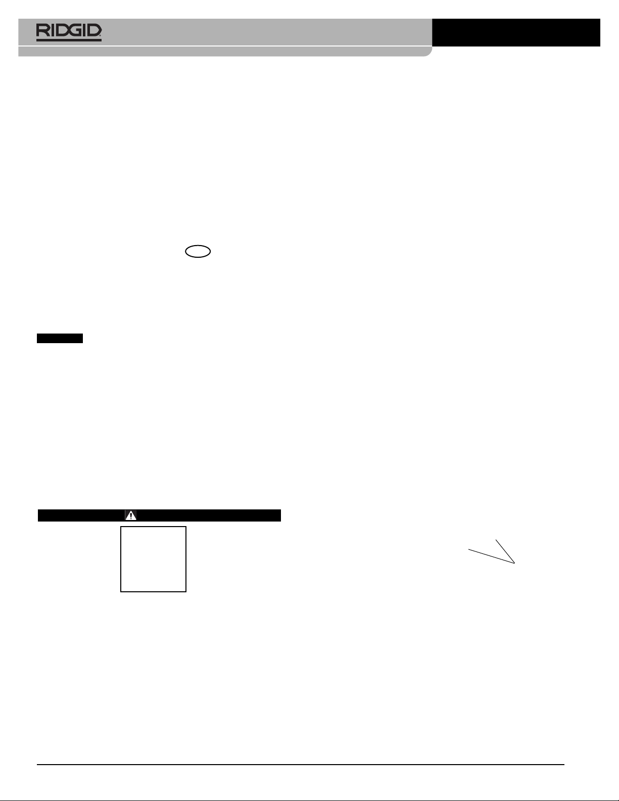
The Threading Machine serial number plate is located on
the end of the base or the back of the base. The last 4 digits indicate the month and year of the manufacture (06 =
June, 14 = 2014).
Figure 3 – Machine Serial Number
NOTICE
lation, joining and forming methods is the responsibility of
the system designer and/or installer. Selection of improper materials and methods could cause system failure.
Stainless steel and other corrosion resistant materials
can be contaminated during installation, joining and forming. This contamination could cause corrosion and premature failure. Careful evaluation of materials and methods
for the specific service conditions, including chemical and
temperature, should be completed before any installation
is attempted.
Selection of appropriate materials and instal-
Mounting on Stands
The Threading Machines can be mounted on various
RIDGID Threader Stands. Refer to RIDGID catalog for
stand information and to the respective Stand Instruction
Sheet for mounting instructions.
Mounting on Bench
The machines can be mounted on a level, stable bench.
To mount the unit on a bench, use four 1/4" - 20 UNC bolts
in holes provided at each corner of the machine base.
Base hole spacing is 12.25" × 18" (311 mm x 457 mm).
Tighten securely.
Mounting on Pipe Legs
Four equal lengths of 1" (25 mm) pipe can be used as a
stand for both the machines. Pipes cut to 33" (0.84 m)
length will place the machine rails approximately 36"
(0.91 m) off the ground. Fully insert the pipes into leg sockets provided on the underside of the base at the corners. Secure with four provided 10 mm hex bolts through
the base. See Figure 4.
Machine Assembly
WARNING
To reduce the risk of serious injury during use, follow these procedures for proper assembly.
Failure to mount the threading machine to a stable
stand or bench may result in tipping and serious
injury.
REV/OFF/FWD switch should be OFF and machine
unplugged before assembly.
Use proper lifting techniques. The RIDGID 300
Compact weighs 147 lb (67 kg) and the 1233 weighs
165 lb (75 kg).
6
Secure
Legs with
Hex Bolts
Figure 4 – Threading Machine Mounted On Pipe Legs

300 Compact/1233 Threading Machines
Pre-Operation Inspection
WARNING
Before each use, inspect your threading machine
and correct any problems to reduce the risk of
serious injury from electric shock, crushing injuries
and other causes, and to help prevent threading
machine damage.
1. Make sure that the threading machine is unplugged
and the REV/OFF/FWD switch is in OFF position.
2. Clean any oil, grease or dirt from the threading
machine, including the handles and controls. This
aids inspection and helps prevent the machine or
control from slipping from your grip. Clean and maintain the machine per the maintenance instructions.
3. Inspect the threading machines for the following:
• Condition of the cords and plug for damage or
modification.
• Proper assembly, maintenance and completeness.
• Any broken, worn, missing, misaligned or binding
parts or other damage.
• Confirm that the REV/OFF/FWD switch is in good
condition and cycles smoothly.
• Presence and readability of warning labels (Fi -
gures 1 & 2).
• Condition of the dies, cutter wheel and reamer cut-
ting edges. Dull or damaged cutting tools increase
required force, produce poor results and increase
the risk of injury.
• Any other condition which may prevent safe and
normal operation.
If any problems are found, do not use the threading
machine until the problems have been repaired.
4. Inspect and maintain any other equipment being
used per its instructions to make sure it is functioning
properly.
Machine and Work Area Set-Up
WARNING
Set up the Threading Machine and the work area
according to these procedures to reduce the risk of
injury from electric shock, machine tipping, entanglement, crushing and other causes, and to help prevent threading machine damage.
Restrict access or barricade the area when work
piece extends beyond machine to provide a minimum of one meter clearance from the work piece.
Restricting access or barricading the work area
around the work piece will reduce the risk of
entanglement.
Secure machine to stable stand or bench. Properly
support pipe. This will reduce the risk of falling
pipe, tipping and serious injury.
1. Check work area for:
• Adequate lighting.
• Flammable liquids, vapors or dust that may ignite.
If present, do not work in area until source is identified, removed or corrected, and area is completely
ventilated. The threading machine is not explosion
proof and can cause sparks.
• Clear, level, stable, dry location for all equipment
and operator.
• Good ventilation. Do not use extensively in small,
enclosed areas.
• Properly grounded electrical outlet of the correct
voltage. Check the machine serial plate for required
voltage. A three-prong or GFCI outlet may not be
properly grounded. If in doubt, have outlet inspected by a licensed electrician.
2. Inspect the pipe to be threaded and associated fittings. Determine the correct equipment for the job, see
specifications. Do not use to thread anything other
than straight stock. Do not thread pipe with fittings or
other attachments. This increases the risk of entanglement.
3. Transport equipment to work area. See Preparing
Machine for Transport for information.
4. Confirm equipment to be used has been properly
inspected and assembled.
5. Confirm that the REV/OFF/FWD switch is in the OFF
position.
7

300 Compact/1233 Threading Machines
6. Check that the correct dies are in the die head and
are properly set. If needed, install and/or adjust the
dies in the die head. See Die Head Set-Up and Use
section for details.
7. Swing the cutter, reamer and die head away up
away from the operator. Make sure they are stable
and will not fall in the work area.
8. If pipe will extend past the chip tray in the front of the
machine or more than 2' (0.6 m) out of the rear of the
machine, use pipe stands to support the pipe and prevent the pipe and threading machine from tipping or
falling. Place the pipe stands in line with machine
chucks, approximately 1/3of distance from end of the
pipe to the machine. Longer pipe may need more
than one pipe stand. Only use pipe stands designed
for this purpose. Improper pipe supports or supporting the pipe by hand can cause tipping or entanglement injuries.
9. Restrict access or set-up guards or barricades to
create a minimum of 3' (1 m) clearance around the
threading machine and pipe. This helps prevent nonoperators from contacting the machine or pipe and
reduces the risk of tipping or entanglement.
the switch to the OFF position. Repeat for REV
position – chuck should rotate clockwise. If the
threading machine does not rotate in the correct
direction do not use the machine until it has been
repaired.
• Move the switch to the FWD position. Inspect the
moving parts for misalignment, binding, odd noises
or any other unusual conditions. Move the switch to
the OFF position. If any unusual conditions are
found, do not use the machine until it has been
repaired.
• Place die head in the use position. Move the switch
to the FWD position. Check for oil flow through
the die head. Move the switch to the OFF position.
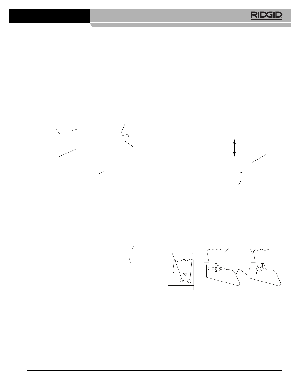
The oil flow can be adjusted with the control valve
on carriage (Figure 5). Clockwise rotation decreas-
es flow and counterclockwise increases flow. Do not
adjust while the machine is running.
-
+
10. Check the level of RIDGID Thread Cutting Oil. Re move the chip tray and oil pan liner; see that the filter
screen assembly is fully submerged in oil. See Oil
System Maintenance. If the machine is equipped
with the drip tray, make sure it properly placed to
direct oil dripping off the die head into the chip tray
(see Figure 5).
11. With the REV/OFF/FWD switch in OFF position, run
the cord along a clear path. With dry hands, plug
the power cord into the properly grounded outlet.
Keep all connections dry and off the ground. If the
power cord is not long enough use an extension
cord that:
• Is in good condition.
• Has a three-prong plug like on the threading
machine.
• Is rated for outdoor use and contains a W or W-A in
the cord designation (e.g. SOW).
• Has sufficient wire size. For extension cords up to
50' (15.2 m) long use 14 AWG (2.5 mm2) or heavier.
For extension cords 50'-100' (15.2 m - 30.5 m) long
use 12 AWG (2.5 mm2) or heavier.
12. Check the threading machine for proper operation.
With hands clear:
• Move the REV/OFF/FWD switch to the FWD posi-
tion. Chuck should rotate counter-clockwise when
viewed from the carriage end (see Figure 23). Move
Control
Control
Valve
Valve
Figure 5 – Adjusting Oil Flow
Drip Tray
13. Confirm the REV/OFF/FWD switch is in OFF position,
and with dry hands unplug the machine.
Die Head Set-Up and Use
The 300 Compact and 1233 Threading Machines can
be used with a variety of RIDGID Die Heads to cut pipe
and bolt threads. Information is included here for QuickOpening, Self-Opening and Receding Self-Opening Die
Heads (1233 only). See the RIDGID catalog for other
available die heads.
Die Heads using Universal Dies for pipe require one set of
dies for each of the following pipe size ranges: (1/8"), (1/4"
and 3/8"), (1/2" and 3/4") and (1" through 2"). NPT/NPSM dies
must be used in NPT die heads and BSPT/BSPP dies
must be used n BSPT die heads – The size bar is marked
for each.
8

300 Compact/1233 Threading Machines
Die heads using Mono or Bolt dies require a dedicated set
of dies for each specific thread size. High speed dies
are recommended for use on 52 rpm machines.
See the RIDGID catalog for dies available for your die
head.
Always cut a test thread to confirm proper thread size after
changing/adjusting the dies.
Removing/Installing Die Head
Insert/remove Die Head Post into mating hole in carriage. When fully inserted, the Die Head will be held in
place. When it is installed, the Die Head can be pivoted on
post to align it with pipe or it can be swung up and out of
the way to allow use of cutter or reamer.
Quick-Opening Die Heads
Quick opening die heads include Model 811A and 531/532
Bolt. Quick opening die heads are manually opened and
closed for user specified thread length.
Washer Tongue
Size Bar
Throwout Lever
Link
Clamp Lever (Hex Nut
on Mono Dies)
Post
3. Loosen clamp lever
(Hex nut on Mono die
Indicator
Line
heads) approximately
three turns.
4. Lift tongue of washer out of slot in size
Indicator
Line
bar. Move washer to
end of slot (Figure 8).
5. Remove dies from the
die head.
Figure 8 – Inserting Dies
6. Insert appropriate dies into the die head, numbered
edge up until the in di cator line is flush with the edge of
the die head (see Figure 8). Numbers on the dies
must correspond with those on the die head slots.
Always change dies as sets – do not mix dies from different sets.
7. Move link index mark to align with desired size mark
on size bar. Adjust die insertion as needed to allow
movement. Washer tongue should be in slot to left.
8. Tighten clamp lever (Hex nut on Mono die heads).
Adjusting Thread Size
1. Install the die head per the Threading Machine instructions and move the die head into threading position.
Dies
Hole for Locking Pin (LH Die Heads)
Figure 6 – Quick-Opening Die Head
Inserting/Changing the Dies
1. Place the die head with numbers facing up.
2. Move throwout lever to OPEN position (Figure 7).
Throwout
Lever
Open
Figure 7 – Open/Closed Lever Position
Throwout
Lever
Closed
2. Loosen clamp lever (Hex nut on Mono die heads).
3. Start with link index mark a ligned with desired size
mark on size bar. On Mono
and Bolt die heads, set link
mark at line in size bar. For
Link
Index
Mark
“Under”
bolt threads with Universal
die head, set all bolt dies at
BOLT line on size bar (Fi -
gure 9).
Size
4. If thread size needs to be ad justed, set the link index mark
Bar
“Over”
slightly off the mark on size
bar in the direction of OVER
(larger dia meter thread, less
Figure 9 – Adjusting
Thread Size
turns of fitting engagement) or UNDER (small er thread
diameter, more turns of fitting engagement) mark ings.
5. Tighten clamp lever.
Opening the Die Head at the End of the Thread
At the end of the thread:
• Pipe Threads – End of threaded pipe is flush with the
end of the number 1 die.
• Bolt Threads – Thread the desired length – watch
closely for any interference between the parts.
9

300 Compact/1233 Threading Machines
Move the throwout lever to the OPEN position, retracting
dies.
Self-Opening Die Heads
The Model 815A Die Heads are self-opening die heads.
For 1/2" through 2" pipe sizes, a trigger can be used to open
the die head when the thread is complete. For 1/8" to 3/8"
sizes, bolt and straight threads, and if desired for the
other sizes, the die head is manually opened when the
thread is complete.
Roll Pin
Index
Line
Lock
Screw
Throwout
Lever
Figure 10 – Universal Self-Opening Die Head
Inserting/Changing the Dies
1. Place the die head with numbers facing up.
2. Make sure the trigger assembly is released and die
head OPEN by pulling the trigger slide away from the
die head. Stay clear of the spring loaded Throwout
Lever while releasing trigger assembly.
Throwout
Lever
Open
Figure 11 – Open/Closed Position
3. Loosen clamp lever ap proximately six full turns.
4. Pull lock screw out of size bar slot so roll pin will
bypass slot. Position size bar so that the index line on
lock screw is a ligned with the RE MOVE DIES mark.
5. Remove dies from the die head.
6. Insert appropriate dies into the die head, numbered
edge up until the indicator line is flush with the edge of
the die head (see Fi gure 12). Num bers on the dies
must cor res pond with those on the die head slots.
Always change dies as sets – do not mix dies from different sets.
“Remove Dies” Mark
Size Bar
Trigger
Assembly
Clamp Lever
Throwout
Lever
Closed
Trigger
Slide
7. Move size bar so in dex
line on lock screw is a ligned with desired size
Indicator
Line
Indicator
Line
mark. Adjust die insertion
as needed to allow movement.
8. Make sure roll pin points
to ward REMOVE DIES
mark.
9. Tighten the clamp lever.
Indicator Line
Figure 12 – Inserting Dies
Adjusting Thread Size
1. Install the die head per the Thread ing Machine Instruc tions and move the die head into threading position.
2. Loosen clamp lever.
3. Position size bar so index line on lock screw is aligned
with desired size mark on size bar.
4. If thread size needs to be ad justed, set the lock screw index
line slightly off the mark on size
bar in the direction of OVER
Lock
Screw
Index
Line
“Over”
(larger dia meter thread, less
turns of fitting engagement) or
UNDER (smaller thread dia meter, more turns of fitting en gagement) markings.
5. Tighten clamp lever.
Size
Bar
Figure 13 – Adjusting
“Under”
Thread Size
Trigger Slide Adjustment
Position the Trigger Slide for the size of pipe being threaded (see Figure 14).
1
•
/2" and 3/4" – End of pipe should
hit foot of Trigger Slide.
1" thru 2"
pipe hit
this
surface
• 1" to 2" – End of pipe should hit
the shank of the Trigger Slide.
For
•1/8", ¼" and 3/8" pipe
• Longer or shorter threads
• Bolt threading
1
/2" and 3/4"
pipe hit this
surface
Figure 14 – Setting
Trigger
Slide
the
Trigger
Push trigger slide up and out of the way. Die head must be
opened manually.
Opening the Die Head at the End of the Thread
When using trigger it will contact the end of pipe, causing
the die head to automatically open. Stay clear of the
spring loaded Throwout Lever when it releases.
To open the die head manually (with trigger slide up), at
the end of the thread:
• Tapered Pipe Threads – End of pipe is flush with
the end of the number 1 die.
10
300 Compact/1233 Threading Machines
• Bolt and Straight Threads – Thread the desired
length – watch closely for any interference between
the parts.
Move the throwout lever to the OPEN position, retracting
dies.
Receding Self-Opening Die Heads
The Model 728 and 928 receding self-opening die heads
are used on 1233 threading machine for 21/2" and 3" pipe
sizes. A trigger is used to open the die head when the
thread is complete, and is adjustable to change thread
length.
Back
Size Bar
Adjustment
“Change
Ball
Ball
Detent
Detent
Nuts
Dies”
Arrow
Adjuster
Knob
Figure 15 – Receding Self-Opening Die Head
Front
Adjuster
Slide
Trigger
Cam Plate
Inserting/Changing the Dies
1. Place the die head with numbers facing up.
2. Pull back on adjuster knob on die head and fully
open die head by sliding cam plate in direction of
CHANGE DIES arrow on cam plate.
4. Pull back on adjuster knob and rotate cam plate to
desired size setting.
5. Engage adjuster knob into slot.
Adjusting Thread Size
1. Loosen the adjustment nut for the desired pipe size.
2. When setting for new dies, start with the adjusting
slide index line aligned with the size mark on the size
bar.
3. If thread size needs to be adjusted, set the index line
slightly off the mark on the size bar in the + direction
(larger thread diameter, less
turns of fitting engage ment)
or in the - direction (smaller
thread diameter, more turns
of fitting engagement) as
shown on the size bar.
4. Tighten the adjustment nut.
Adjusting Thread Length
1. Loosen the screw on bot-
+
-
Size
Bar
Adjustment
Slide Index
Line
tom trigger.
2. For short threads, shift the
bottom trigger towards the
machine spindle. For long
Adjustment
Nut
Figure 17 – Adjusting
Thread Size
threads, shift it away from the spindle (see Figure 18
– factory settings shown). Long threads are typically
preferred in Far East and short threads in Europe. Set
as desired.
3. Re-tighten the screw.
For Long
Threads
For Short
Threads
Top Trigger
Figure 16 – Inserting Dies
3. Remove dies from die head.
Insert appropriate dies into the die head, numbered
edge up. Numbers on the dies must correspond with
those on the die head slots (see Figure 16). The die
slots have a ball detent that engages with the groove
on dies when properly installed. Always change dies
as sets – do not mix dies from different sets.
Groove
Bottom
Trigger
Top Trigger Hole
Location
Figure 18 – Adjusting Thread Length
Short Threads Long Threads
11
300 Compact/1233 Threading Machines
Preparing the Die Head to Thread
Lower the die head down into the threading position.
Firmly push on adjusting slide to set/close the die head
(Figure 19).
Figure 19 – Closing the Receding Die Head
Opening the Die Head at the End of the Thread
The die head trigger will contact end of pipe causing the die
head to automatically open.
Operating Instructions
Do not use this machine to make or break (tighten
or loosen) fittings. This can cause striking or crushing injuries.
One person must control the work process and
machine operation. Only the operator should be in
the work area when the machine is running. This
helps reduce the risk of injury.
Follow operating instructions to reduce the risk of
injury from entanglement, striking, crushing and
other causes.
1. Make sure that machine and work area is properly set
up and that the work area is free of bystanders and
other distractions. The operator should be the only
person in the area while the machine is operated.
The cutter, reamer and die head should be up away
from the operator, do not place in the operating position. Make sure they are stable and will not fall. Fully
open the chucks of the threading machine.
2. Insert pipe shorter than 2' (0,6 m) from the front of the
machine. Insert longer pipes through either end so
that the longer section extends out beyond the rear of
the Threading Machine. Confirm that pipe stands
are properly placed.
3. If needed, mark the pipe. Place pipe so that the area
to be cut or end to be reamed or threaded is approximately 4" (100 mm) from the front of the chuck. If closer, the carriage may strike the machine during the
threading and damage the machine.
WARNING
Operate the machine from the operator control
(switch) side. Be sure you can control the switch at
all times. Operating the machine from the switch
side improves control and eliminates need to reach
over the machine. Switch control helps to reduce
the risk of serious injury.
Do not leave machine running unattended. Place
switch in OFF position when plugging in and not in
use to reduce the risk of entanglement.
Do not wear gloves or loose clothing. Keep sleeves
and jackets buttoned. Loose clothing can become
entangled in rotating parts and cause crushing and
striking injuries.
Keep hands away from rotating pipe and parts.
Stop the machine before wiping threads or screwing on fittings. Do not reach across the machine or
pipe. To prevent entanglement, crushing or striking
injuries, allow machine to come to a complete stop
before touching the pipe or machine chucks.
Do not wear gloves. Gloves may be entangled by
the rotating pipe or machine parts leading to personal injury.
4. Turn the rear centering device counterclockwise
(viewed from rear of machine) to close down onto
pipe. Make sure that the pipe is centered in the inserts.
This improves pipe support and gives better results.
Close
Figure 20 – Chucking Pipe
Open
5. Turn the front chuck handwheel counterclockwise
(viewed from front of machine) to close down onto
pipe. Make sure that the pipe is centered in the inserts.
12

300 Compact/1233 Threading Machines
Use repeated and forceful counterclockwise spins of
the handwheel to secure the pipe in front chuck.
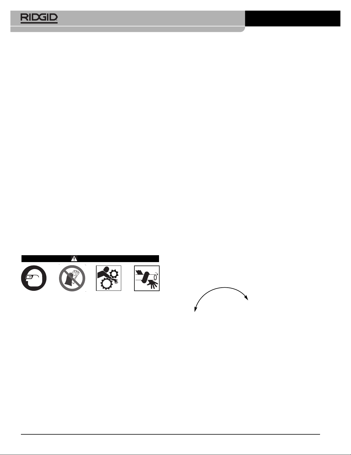
6. Assume a proper operating position to help maintain
control of the machine and pipe (See Figure 21).
• Stand on the REV/OFF/FWD switch side of the
machine with convenient access to the tools and
switch. Be sure you can control the switch at all
times. Do not turn the machine ON yet.
• Be sure that you have good balance and do not
have to overreach.
Cutting
1. Open cutter by turning the feed screw counterclockwise. Lower the cutter into cutting position over the
pipe. Use the carriage handwheel to move the cutter
over the area to be cut, and align the cutter wheel with
the mark on the pipe. Cutting threaded or damaged
sections of pipe can damage the cutter wheel.
2. Tighten the cutter feed screw handle to bring the
cutter wheel firmly in contact with the pipe while
keeping the cutter wheel aligned with the mark on the
pipe.
3. Move the REV/OFF/FWD switch to the FWD position.
4. With both hands, grasp the pipe cutter feed handle.
5. Tighten the feed screw handle one-half turn per rotation of the pipe until the pipe is cut. More aggressive
tightening of the handle reduces cutter wheel life
and increases pipe burr formation. Do not support the
pipe by hand. Let the cut off piece be supported by
the threading machine carriage and pipe stand.
Figure 21 – Operating Position
Figure 22 – Cutting Pipe with Cutter
6. Move the REV/OFF/FWD switch to the OFF position.
7. Raise cutter into position up away from operator.
Reaming
1. Move the reamer into reaming position. Make sure
that it is securely positioned to prevent it from moving
during use.
2. Move the REV/OFF/FWD switch to the FWD position.
3. With both hands, grasp the carriage handwheel.
4. Turn carriage handwheel to move the reamer to the
end of the pipe. Apply slight pressure to the handwheel to feed the reamer into pipe to remove the
burr as desired.
13

300 Compact/1233 Threading Machines
FWD (1) REV (2)REV (2)
handwheel to start the die head onto the pipe. Once
the die head starts threading the pipe, no more force
is required on the carriage handwheel.
6. Keep your hands away from the rotating pipe. Make
sure the carriage does not hit the machine. When the
thread is complete, open the die head. Do not run
machine in Reverse (REV) with dies engaged.
7. Move the REV/OFF/FWD switch to the OFF position.
8. Turn the carriage handwheel to move the die head
past the end of the pipe. Raise the die head into
position up away from the operator.
Figure 23 – Reaming Pipe with Reamer, Machine Rotation
5. Move the REV/OFF/FWD switch to the OFF position.
6. Move the reamer up away from the operator.
Threading Pipe
Due to differing pipe characteristics, a test thread should
always be performed before the first thread of the day or
when changing pipe size, schedule or material.
1. Lower the die head into the threading position. Con firm that the dies are correct for the pipe being threaded and properly set. See the “Die Head Set-Up and
Use” section for information on changing and adjusting dies.
9. Remove the pipe from the machine and inspect the
thread. Do not use the machine to tighten or loosen fittings on the thread.
Threading Bar Stock/Bolt Threading
Bolt threading is similar to the pipe threading process. The
stock diameter should never exceed the thread major
diameter.
When cutting bolt threads, the correct dies and die head
must be used. Bolt threads may be cut as long as needed, but make sure the carriage does not hit the machine.
If long threads are required:
1. At the end of carriage travel, leave the die head
closed, and move the REV/OFF/FWD switch to the
OFF position.
2. Open the chuck and move the carriage and workpiece
to the end of the machine.
3. Re-chuck the rod and continue threading.
Left Hand Threading
Cutting left hand threads is similar to the right hand
threading process. Left hand threading is possible with 300
Compact threading machine with REV/OFF/FWD switch
only. To cut left hand threads, left hand die heads and dies
are required.
Figure 24 – Threading Pipe (811-A Quick Opening Die
Head shown)
2. Close the die head.
3. Move the REV/OFF/FWD switch to the FWD position.
4. With both hands, grasp the carriage handwheel.
Confirm cutting oil flow through the die head.
5. Turn carriage handwheel to move the die head to the
end of the pipe (Figure 24). Apply slight force to the
14
1. Change the oil pump connections to allow oil flow
when the machine is run in reverse (REV). See Figure
25. Be sure to return the connections to their original
configuration when returning to right hand threading.
Always replace cover before use.

Pump In (REV)
From Filter
300 Compact/1233 Threading Machines
Pin
Holes
Holes
Pin
Pump Out (FWD)
To Carriage
Figure 25A – Oil Pump Connections for Left Hand
Threading (Switch in REV)
Pump Out (FWD)
From Filter
Pump In (REV)
To Carriage
Figure 25B – Oil Pump Connections for Right Hand
Threading (Switch in “FWD”)
Figure 25C – Cover in Place
2. Place a 5/16" pin 2" long through the holes in carriage
rest and left hand die head to retain in place (see
Figure 26).
Figure 26 – Retaining LH Die Head in Place
Removing Pipe from the Machine
1. With the REV/OFF/FWD switch in the OFF position
and the pipe stationary, use repeated and forceful
clockwise spins of the handwheel to loosen the pipe
in the chuck. Open the front chuck and the rear-centering device. Do not reach into chuck or centering
device.
2. Firmly grip the pipe and remove from the machine.
Carefully handle the pipe as the thread may still be hot
and there may be burrs or sharp edges.
Inspecting Threads
1. After removing the pipe from the machine, clean the
thread.
2. Visually inspect thread. Threads should be smooth
and complete, with good form. If issues such as
thread tearing, waviness, thin threads, or pipe out-ofroundness are found, the thread may not seal. Refer
to the Troubleshooting Chart for help in diagnosing
these issues.
3. Inspect the size of the thread.
• The preferred method of checking thread size is
with a ring gauge. There are various styles of ring
gauges, and their usage may differ from that shown
here.
• Screw ring gauge onto the thread hand tight.
• Look at how far the pipe end extends through the
ring gage. The end of the pipe should be flush with
the side of the gauge plus or minus one turn. If
thread does not gauge properly, cut off the thread,
adjust the die head and cut another thread. Using a
thread that does not gauge properly can cause
leaks.
Ring
Gauge
Flush
(Basic Size)
One Turn Large
(Maximum Size)
One Turn Small
(Minimum Size)
Figure 27 – Checking Thread Size
15

300 Compact/1233 Threading Machines
• If a ring gauge is not available to inspect thread
size, it is possible to use a new clean fitting representative of those used on the job to gauge thread
size. For 2" and under NPT threads, the threads
should be cut to obtain 4 to 5 turns to hand tight
engagement with the fitting and for BSPT it should
be 3 turns. For 21/2" to 3" NPT threads the hand tight
engagement should be 5.5 to 6 threads, and for
BSPT it should be 4 threads.
4. See “Adjusting Thread Size” under “Die Head Set-
Up and Use” heading to adjust thread size.
5. Test the piping system in accordance with local codes
and normal practice.
Preparing Machine for Transport
1. Make sure that the REV/OFF/FWD switch is in the
OFF position and the cord is unplugged from the
outlet.
2. Clean the chips and other debris from the chip tray.
Remove or secure all equipment and material from
the machine and stand prior to moving to prevent
falling or tipping. Clean up any oil or debris on the
floor.
If the jaw inserts do not grip and need to be cleaned, use
a wire brush to remove any build up of pipe scale, etc.
Lubrication
On a monthly basis (or more often if needed) lubricate all
exposed moving parts (such as carriage rails, cutter
wheels and rollers, cutter feed screw, jaw inserts and
pivot points) with a light lubricating oil. Wipe any excess oil
from exposed surfaces.
Clean the lubrication points to remove dirt and prevent
contamination of the oil or grease. Lubricate on a monthly basis.
300 Compact: Use a grease gun to add a Lithium EP
(Extreme Pressure) grease through the grease fittings in
the lubrication points.
1233: Fill the lubrication points with lubricating oil. Press
the ball in the lubrication point to allow the oil to reach
bearings.
3. Place the cutter, reamer and die head in the operating position.
4. Coil up the power cord.
5. If needed, remove the machine from the stand. Use
proper lifting techniques, be aware of the machine
weight. Machine is equipped with four hand grips at
corners. Use care in lifting and moving.
Maintenance Instructions
WARNING
Make sure that the REV/OFF/FWD switch is in the
OFF position and the machine is unplugged before
performing any maintenance or making any adjustments.
Always wear eye protection.
Maintain threading machine according to these
procedures to reduce the risk of injury from electrical shock, entanglement and other causes.
Cleaning
After each use, empty the threading chips from the chip
tray and wipe out any oil residue. Wipe oil off exposed surfaces, especially areas of relative motion like the carriage rails.
Lubrication Points
Figure 28 – Lubrication Points
Oil System Maintenance
Keep the oil filter screen clean for sufficient oil flow. Oil filter screen is located in the bottom of oil reservoir. Loosen
the screw that secures filter to base, remove filter from oil
line and clean. Do not operate machine with oil filter
screen removed.
Filter
Screen
Oil Drain
Chip Tray
Oil Pan
Liner
16
Figure 29 – Filter Screen Assembly

Replace thread cutting oil when it becomes dirty or contaminated. To drain the oil, position a container under drain
plug at end of reservoir and remove plug. Follow all local
laws and regulations when disposing of oil. Clean build up
from the bottom of the reservoir. Use RIDGID Thread Cut ting Oil for high quality threads and maximum die life. See
the Specification section for reservoir oil capacity.
The oil pump should self-prime if the system is clean. If it
does not, this indicates that the pump is worn and should
be serviced. Do not attempt to prime the pump.
Replacing Cutter Wheel
If the cutter wheel becomes dull or broken, push cutter
wheel pin out of frame and check for wear. Replace pin if
worn and install new Cutter Wheel (see catalog). Lubricate
pin with light lubricating oil.
Replacing Jaw Inserts
If Jaw inserts are worn out and do not grip pipe, they need
to be replaced.
300 Compact/1233 Threading Machines
Motor Cover
Brush Cap
1. Place screwdriver in insert slot and turn 90 degrees in
either direction. Remove insert (Figure 30).
2. Place insert sideways on locking pin and press down
as far as possible (Figure 30).
PRESS
DOWN
Screw Driver
Insert
To Remove
Figure 30 – Replacing Jaw Inserts
Locking
To Replace
Pin
‘
Teeth
3. Hold insert down firmly, and with screwdriver, turn so
teeth face up.
Replacing Carbon Brushes
Check motor brushes every 6 months. Replace when
worn to less than 1/2".
Figure 31 – Removing Motor Cover/Changing Brushes
3. Unscrew brush caps. Remove and inspect brushes.
Replace when worn to less than 1/2". Inspect the commutator for wear. If excessively worn, have machine
serviced.
4. Re-install brushes/install new brushes. Reassemble
unit. Install all covers before operating machine.
1. Unplug the machine from power source.
2. Loosen the two motor cover screws and remove
motor cover at rear of machine.
17

300 Compact/1233 Threading Machines
Optional Equipment
WARNING
To reduce the risk of serious injury, only use equipment specifically designed and recommended for
use with the RIDGID Threading Machines.
Catalog Model
No. No. Description
97075 815A 1/8" - 2" NPT, Self-Opening, RH Die Head
97065 811A 1/8" - 2" NPT, Quick-Opening, RH Die Head
97080 815A 1/8" - 2" BSPT, Self-Opening, RH Die Head
45322 815A 1/8" - 2" BSPT, Self-Opening, RH EUR. RT
97070 811A 1/8" - 2" BSPT, Quick-Opening, RH Die Head
97045 531 1/4" - 1" Bolt, Quick-Opening, RH/LH Die Head
97050 532 11/4" - 2" Bolt, Quick-Opening, RH/LH Die Head
67657 250 Folding Wheel Stand
58077 250 Folding Wheel Stand
92457 100A Universal Leg & Tray Stand
92462 150A Universal Wheel & Tray Stand
92467 200A Universal Wheel & Cabinet Stand
51005 819 Nipple Chuck, 1/2" - 2" NPT
68160 819 Nipple Chuck, 1/2" - 2" BSPT
For 300 Compact Only
84537 816 1/8" - 3/4" Semi-Automatic Die Head
84532 817 1" - 2" Semi-Automatic Die Head
67662 — 916 Groover Adapter Bracket
For 1233 Only
54437 728 21/2" - 3" NPT, Receding Self-Opening, RH Die Head
93562 928 21/2" - 3" BSPT, Receding Self-Opening, RH Die Head
— 419 Nipple Chuck
For a complete listing of RIDGID equipment available for the 300 Compact or 1233 Threading
Machine, see the Ridge Tool Catalog online at
www.RIDGID.com or call Ridge Tool Technical
Service Department (800) 519-3456, from the U.S.
and Canada.
Service And Repair
WARNING
Improper service or repair can make machine
unsafe to operate.
The Maintenance Instructions will take care of most of the
service needs of this machine. Any problems not ad dressed by this section should only be handled by an
authorized RIDGID service technician.
Tool should be taken to a RIDGID Independent Service
Center or returned to the factory. Only use RIDGID service
Parts.
For information on your nearest RIDGID Independent
Service Center or any service or repair questions:
• Contact your local RIDGID distributor.
• Visit www.RIDGID.com or to find your local RIDGID
contact point.
• Contact Ridge Tool Technical Service Department at
rtctechservices@emerson.com, or in the U.S. and
Canada call (800) 519-3456.
Disposal
Parts of the Threading Machine contain valuable materials and can be recycled. There are companies that
specialize in recycling that may be found locally. Dispose
of the components and any waste oil in compliance with
all applicable regulations. Contact your local waste management authority for more information.
Thread Cutting Oil Information
Read and follow all instructions on the threading oil label
and Safety Data Sheet (SDS). Specific information about
RIDGID Thread Cutting Oils, including Hazard Identi fi ca tion,
First Aid, Fire Fighting, Accidental Release Measures,
Handling and Storage, Per sonal Protective Equipment,
Disposal and Transportation, is included on the container
and SDS. SDS is available at www.RIDGID.com or by
contacting Ridge Tool Technical Service Department at
(800) 519-3456 in U.S. and Canada or rtctech servic es@em erson.com.
Machine Storage
WARNING
indoors or well covered in rainy weather. Store the machine
in a locked area that is out of reach of children and people
unfamiliar with threading machines. This machine can
cause serious injury in the hands of untrained users.
18
The Threading Machines must be kept

300 Compact/1233 Threading Machines
Troubleshooting
PROBLEM POSSIBLE REASONS SOLUTION
Torn threads.
Out-of-round or crushed
threads.
Thin threads.
No cutting oil flow.
Damaged, chipped or worn out dies.
Incorrect cutting oil.
Insufficient cutting oil.
Dirty or contaminated oil.
Die head not properly aligned with pipe.
Improper pipe.
Die head not properly set.
Carriage not moving freely on rails.
Die head set undersize.
Pipe wall thickness too thin.
Dies inserted into head in wrong order.
Forcing carriage feed handle during threading.
Die head cover plate screws are loose.
Low or no cutting oil.
Machine set up for Left Hand Threading.
Oil Screen Plugged.
Oil flow rate not properly set.
Die head not in the threading (DOWN) position.
Replace dies.
Only use RIDGID®Thread Cutting Oil.
Check oil flow rate and adjust as needed.
Replace the RIDGID®Thread Cutting Oil.
Clean chips, dirt or other foreign material from
between die head and carriage.
Recommend using with black or galvanized steel
pipe.
Pipe wall too thin – use schedule 40 or heavier
pipe.
Adjust die head to give proper size thread.
Clean and lubricate carriage rails.
Adjust die head to give proper size thread.
Use schedule 40 or heavier pipe.
Put dies in proper position in die head.
Once dies have started thread, do not force carriage feed handle. Allow carriage to self-feed.
Tighten screws.
Fill oil reservoir.
Reverse the oil pump hoses (see section on Left
Hand Threading).
Clean Screen.
Adjust oil flow rate.
Move die head to the threading position.
Machine will not run.
Pipe slips in jaws.
Motor brushes worn out.
Jaw inserts loaded with debris.
Jaws inserts worn out.
Pipe not properly centered in jaw inserts.
Chuck not tight on pipe.
Replace brushes.
Clean jaw inserts with wire brush.
Replace jaw inserts.
Make sure pipe is centered in jaw inserts, use the
rear centering device.
Use repeated and forceful counterclockwise spins of
the handwheel to secure the pipe in front chuck.
19

300 Compact/1233 Threading Machines
20

Fileteuses
300 Compact et 1233
AVERTISSEMENT
Familiarisez-vous avec le mode
d’emploi ci-présent avant d’utiliser
l’appareil. Tout manquement aux
consignes avancées dans ce ma nuel augmenterait les risques de
choc électrique, d’incendie et/ou
de blessure grave.
300 Compact
1233
Fileteuses 300 Compact et 1233
Enregistrez ici le numéro de série indiqué sur la plaque signalétique de l’appareil pour future référence
N° de
série

Fileteuses 300 Compact et 1233
Table des matières
Fiche d’enregistrement du numéro de série de la machine ........................................................................................................21
Symboles de sécurité ......................................................................................................................................................................23
Consignes de sécurité générales visant les appareils électriques
Sécurité des lieux..........................................................................................................................................................................23
Sécurité électrique ........................................................................................................................................................................23
Sécurité individuelle ......................................................................................................................................................................24
Utilisation et entretien des appareils ............................................................................................................................................24
Service après-vente ......................................................................................................................................................................25
Consignes de sécurité spécifiques
Sécurité des fileteuses transportables ..........................................................................................................................................25
Description, caractéristiques techniques et équipements de base
Description ....................................................................................................................................................................................26
Caractéristiques techniques..........................................................................................................................................................26
Equipements de base ..................................................................................................................................................................27
Montage des machines
Montage sur support ....................................................................................................................................................................27
Montage sur établi ........................................................................................................................................................................27
Montage sur jambages tubulaires ................................................................................................................................................27
Inspection préalable ........................................................................................................................................................................28
Préparation de la machine et du chantier......................................................................................................................................28
Préparation et utilisation des têtes de filière
Dépose et montage des têtes de filière ........................................................................................................................................30
Têtes de filière à ouverture rapide ................................................................................................................................................30
Installation et remplacement des filières ....................................................................................................................................31
Réglage du pas de filetage ........................................................................................................................................................31
Ouverture de la tête de filière en fin de filetage ........................................................................................................................30
Têtes de filière à ouverture automatique ......................................................................................................................................31
Installation et remplacement des filières ....................................................................................................................................31
Réglage du pas de filetage ........................................................................................................................................................32
Ouverture de la tête de filière en fin de filetage ........................................................................................................................32
Têtes de filière rétractables à ouverture automatique ..................................................................................................................32
Installation et remplacement des filières ....................................................................................................................................33
Réglage du pas de filetage ........................................................................................................................................................33
Réglage de la longueur de filetage ............................................................................................................................................33
Préparation de la tête de filière ..................................................................................................................................................33
Ouverture de la tête de filière en fin de filetage ........................................................................................................................34
Consignes d’utilisation
Coupe............................................................................................................................................................................................35
Alésage ........................................................................................................................................................................................35
Filetage des tuyaux ......................................................................................................................................................................36
Filetage des ronds et boulons ......................................................................................................................................................36
Filetage à gauche..........................................................................................................................................................................36
Retrait des tuyaux de la machine..................................................................................................................................................37
Contrôle des filetages ..................................................................................................................................................................37
Préparation de la machine au transport ........................................................................................................................................38
Consignes d’entretien
Nettoyage......................................................................................................................................................................................38
Lubrification ..................................................................................................................................................................................38
Entretien du système de lubrification ............................................................................................................................................38
Remplacement du galet de coupe ................................................................................................................................................39
Remplacement des mors de mandrinage ....................................................................................................................................39
Remplacement des balais ............................................................................................................................................................39
Accessoires......................................................................................................................................................................................40
Huile de coupe ................................................................................................................................................................................40
Stockage de la machine ..................................................................................................................................................................40
Révisions et réparations ................................................................................................................................................................40
Recyclage ........................................................................................................................................................................................40
Dépannage........................................................................................................................................................................................41
Garantie à vie ..............................................................................................................................................................Page de garde
*Traduction de la notice originale
22

Fileteuses 300 Compact et 1233
Symboles de sécurité
Les symboles et mots clés utilisés à la fois dans ce mode d’emploi et sur l’appareil lui-même servent à signaler
d’importants risques de sécurité. Ce qui suit permettra de mieux comprendre la signification de ces mots clés et symboles.
Ce symbole sert à vous avertir de risques d’accident potentiels. Le respect des consignes qui le suivent vous permettra d’éviter
les risques d’accident grave ou potentiellement mortel.
DANGER
AVERTISSEMENT
ATTENTION
AVIS IMPORTANT
Ce symbole indique la nécessité de bien se familiariser avec la notice d’emploi avant d’utiliser ce matériel. La notice
d’emploi renferme d’importantes consignes de sécurité et d’utilisation du matériel.
Ce symbole indique la nécessité du port systématique de lunettes de sécurité fermées ou avec oeillères lors de la manipulation ou de l’utilisation de ce matériel afin de limiter les risques de lésions oculaires.
Ce symbole signale un risque de blessure par l’enchevêtrement des doigts, des mains, des vêtements ou autres objets portés
dans les engrenages de l’appareil.
Le terme DANGER signifie une situation dangereuse qui, faute d’être évitée, provoquerait la mort ou de graves blessures
corporelles.
Le terme AVERTISSEMENT signifie une situation dangereuse potentielle qui, faute d’être évitée, serait susceptible d’entraîner la mort ou de graves blessures corporelles.
Le terme ATTENTION signifie une situation dangereuse potentielle qui, faute d’être évitée, serait susceptible d’entraîner des blessures corporelles légères ou modérées.
Le terme AVIS IMPORTANT indique des informations concernant la protection des biens.
Ce symbole signale un risque de blessure par l’enveloppement des doigts, des jambes, des vêtements ou autres objets portés
autour des arbres rotatifs du matériel.
Ce symbole signale un risque de choc électrique.
Ce symbole signale un risque de blessure en cas de renversement de l’appareil.
Ce symbole interdit le port de gants lors de l’utilisation de l’appareil afin de limiter les risques de blessure.
Consignes générales de sécurité
AVERTISSEMENT
Familiarisez-vous avec l’ensemble des consignes
de sécurité, consignes d’utilisation, illustrations et
caractéristiques techniques ci-présentes afin
d’éviter les risques de choc électrique, d’incendie
et/ou de grave blessure corporelle.
Conservez l’ensemble des consignes de
sécurité et d’utilisation pour future référence!
Le terme « appareil électrique » utilisé dans les consignes de sécurité vise à la fois les appareils électriques
sur secteur et les appareils à piles.
Sécurité du chantier
• Assurez-vous de la propreté et du bon éclairage
des lieux. Les chantiers encombrés ou mal éclairés
sont une invitation aux accidents.
• N’utilisez pas d’appareils électriques en présence
de substances volatiles telles que liquides, gaz ou
poussières combustibles. Ce type de matériel risque
de produire des étincelles susceptibles d’enflammer les
poussières et émanations combustibles.
• Eloignez les enfants et les curieux durant l’utili -
sation des appareils électriques. Les fiches et prises
électriques non modifiées limitent les risques de choc
électrique.
Sécurité électrique
• La fiche de l’appareil doit correspondre à la prise de
courant utilisée. Ne jamais tenter de modifier la
fiche d’une manière quelconque. Ne jamais utiliser
d’adaptateur de prise sur les appareils équipés
d’une fiche avec terre. Les fiches et prises électriques
non modifiées limitent les risques de choc électrique.
• Evitez tout contact avec des objets reliés à la terre
tels que canalisations, radiateurs, cuisinières et ré frigérateurs. Tout contact avec la terre augmenterait
les risques de choc électrique.
• N’exposez pas les appareils électriques aux intem-
péries. La moindre pénétration d’eau à l’intérieur de
ces appareils augmenterait les risques de choc électrique.
• Ne maltraitez pas le cordon d’alimentation de l’ap -
pareil. Ne jamais utiliser le cordon pour porter,
23

Fileteuses 300 Compact et 1233
tirer ou débrancher l’appareil. Eloignez le cordon
de la chaleur, des matières grasses, des objets
tranchants et des mécanismes. Les cordons d’ali -
men tation endommagés ou entortillés augmentent
les risques de choc électrique.
• Lors de l’utilisation de l’appareil à l’extérieur, pré -
voyez une rallonge électrique homologuée pour ce
type d’emploi. Ce type de rallonge limitera les risques
de choc électrique.
• S’il est inévitable d’utiliser l’appareil dans des
endroits humides, prévoyez une source d’alimen tation protégée par disjoncteur différentiel. La
présence d’un disjoncteur différentiel limitera les
risques de choc électrique.
Sécurité individuelle
• Soyez attentif, restez concentré et faites preuve
de bon sens lors de l’utilisation de ce type d’ap pareil. Ne jamais utiliser ce matériel lorsque vous
êtes fatigué ou sous l’influence de drogues, de
l’alcool ou de médicaments. Lors de l’utilisation d’un
appareil électrique, un instant d’inattention risque
d’entraîner de graves lésions corporelles.
• Prévoyez les équipements de protection indivi -
duelle appropriés. Portez systématiquement une
protection oculaire. Selon le cas, le port d’un masque
à poussière, de chaussures de sécurité antidérapantes, du casque ou d’une protection auriculaire
peut aider à limiter les risques de lésion corporelle.
• Evitez les risques de démarrage accidentel de
l’appareil. Assurez-vous que son interrupteur
marche/arrêt se trouve en position « arrêt » avant
de le brancher, d’y installer un bloc-piles ou de le
manipuler. Porter un appareil électrique avec son
doigt sur la gâchette, ou bien brancher un appareil
électrique lorsque son interrupteur est en position
« marche », serait une invitation aux accidents.
• Retirez toute clé ou dispositif de réglage éventuel
avant de mettre l’appareil en marche. Maintenez
une bonne assiette et un bon équilibre à tout
moment. Une clé ou tout autre dispositif de réglage
engagé sur un élément mécanique pourrait provoquer un accident.
• Ne vous mettez pas en porte-à-faux. Maintenez
une bonne assiette et un bon équilibre à tout
moment. Cela assurera un meilleur contrôle de
l’appareil en cas d’imprévu.
• Habillez-vous de manière appropriée. Ne portez
pas de vêtements trop amples ou de bijoux.
Eloignez vos cheveux et vos vêtements des mé -
canis mes lorsque l’appareil fonctionne. Les vête-
ments amples, les bijoux et les cheveux longs risquent
d’être entraînés par les mécanismes en rotation.
• Lorsque l’appareil est pourvu d’un système de
récupération de poussière, s’assurer que le système est correctement connecté et utilisé. Les
systèmes de récupération de poussière peuvent limiter
les risques associés à l’inhalation des poussières.
• Ne laissez pas votre familiarité avec un appareil se
développer en complaisance vis-à-vis des règles
de sécurité applicables. La moindre inattention peut
occasionner un accident grave en un clin d’œil.
Utilisation et entretien de l’appareil
• Ne pas forcer l’appareil. Prévoyez l’appareil le
mieux adapté aux travaux envisagés. Un appareil
adapté produira de meilleurs résultats et un meilleur
niveau de sécurité lorsqu’il fonctionne au régime prévu.
• Ne pas utiliser d’appareil dont l’interrupteur mar -
che/ arrêt ne fonctionne pas correctement. Tout
appareil qui ne peut pas être contrôlé par son interrupteur est considéré dangereux et doit être réparé.
• Débrancher l’appareil ou retirez son bloc-piles
avant tout réglage, remplacement d’outils ou stockage. De telles mesures préventives aideront à limiter
les risques de démarrage accidentel de l’appareil.
• Ranger tout appareil non utilisé hors de la portée
des enfants. L’utilisation de cet appareil doit être
strictement réservé à du personnel compétent
disposant d’une formation adéquate. Ce type
d’appareil peut devenir dangereux entre les mains
d’un novice.
• Assurer l’entretien approprié de l’appareil. S’as -
surer de l’absence d’éléments grippés ou endommagés, voire toute autre anomalie susceptible de
nuire au bon fonctionnement et à la sécurité de
l’appareil. Ne pas utiliser d’appareil endommage
avant sa réparation. De nombreux accidents sont
le résultat d’appareils mal entretenus.
• Assurer l’affutage et la propreté des outils de
coupe. Des outils de coupe correctement entretenus
et affutés sont moins susceptibles de se gripper et sont
plus faciles à contrôler.
• Assurer la parfaite propreté de toutes surfaces
manipulables. Lorsqu’ils sont encrassés, les leviers et
autres points de prise en main peuvent nuire à la
sécurité d’utilisation de l’appareil en cas d’imprévu.
• Utiliser l’appareil, ses accessoires et ses outils de
coupe selon les consignes ci-présentes, tout en
24

Fileteuses 300 Compact et 1233
tenant compte des conditions de travail et d’exé cution envisagées. Toute déviation de l’emploi prévu
pour cet appareil électrique augmenterait les risques
d’accident grave.
Service après-vente
• Confiez la révision de votre appareil électrique à un
réparateur qualifié utilisant exclusivement des
pièces de rechange identiques. Cela assurera la
sécurité opérationnelle de l’appareil.
Consignes de sécurité
spécifiques
AVERTISSEMENT
La section suivante contient d’importantes consignes de sécurité visant ce type d’appareil en
particulier.
Afin de limiter les risques de choc électrique et
autres lésions corporelles graves, familiarisezvous avec celles-ci avant d’utiliser les fileteuses
300 Compact et 1233.
CONSERVEZ CES CONSIGNES !
Gardez cette notice à portée de main de tout utilisateur
éventuel.
Sécurité des fileteuses transportables
Cette fileteuse n’est pas équipée de pédale de commande. La présence d’une pédale de commande est
obligatoire sur certains marchés, notamment ceux des
Etats-Unis, du Canada, de l’Australie, de l’Union
Européenne, de la Russie, de la Turquie et de l’Arabie
Saoudite. Ne jamais utiliser de machine sans pédale de
commande lorsque la présence de celle-ci fait partie des
normes en vigueur. Les pédales de commande assurent
non-seulement une meilleure fonctionnalité, mais aussi
une meilleure sécurité. Toute pédale de commande obligatoire doit être reliée directement à la machine.
• Nettoyez les sols de la zone de travail. Les sols glis-
sants sont une invitation aux accidents.
• Assurez un périmètre de sécurité d’un mètre au tour
de la zone de travail dès que l’ouvrage dépasse le
gabarit de la machine. Une barrière ou barricade
périmétrique positionnée au-delà de l’ouvrage limitera
les risques d’enchevêtrement.
• Ne portez pas de gants. Les gants risquent de
s’entortiller autour du tuyau ou des mécanismes et
provoquer de graves blessures.
• Ne pas l’utiliser cette machine à d’autres fins, tel
que pour le perçage de trous ou l’entraînement
de treuils. L’application non prévue ou la modification
de cette machine augmenterait les risques d’accident
grave.
• Cette machine est prévue pour effectuer la coupe,
l’alésage et le filetage des tuyaux selon les instructions ci-présentes. Elle ne doit pas être utilisée avec
des appareils nécessitant une pédale de commande,
tels que les fileteuses démultipliées et les rainureuses
à galets.
• Arrimez la machine à un banc ou support. Soute nez
les tuyaux de grande longueur à l’aide de portetubes. Cela limitera les risques de renversement de
l’ensemble.
• En cours d’opération, tenez-vous du côté de l’in -
terrup teur de la machine afin de pouvoir y accéder
à tout moment. Cela vous permettra de mieux con-
trôler l’opération et ce, sans avoir à vous pencher de
l’autre côté de la machine. L’interrupteur aide à limiter
les risques d’accident grave.
• Ne pas laisser la machine tourner sans supervi-
sion. Afin de limiter les risques d’enchevêtrement,
mettez son interrupteur en position « OFF » avant
de vous en éloigner.
• Eloignez vos mains des tuyaux et raccords en
rotation. Eteignez la machine avant d’essuyer ou
de visser les raccords. Attendez que la machine
soit complètement arrêtée avant de manipuler le
tuyau. Ceci limitera les risques d’enchevêtrement
dans les mécanismes rotatifs.
• Ne pas utiliser cette machine pour le montage ou
démontage forcé des raccords. Cette machine
n’est pas prévue pour ça. Une telle pratique pourrait
entraîner le blocage, l’enchevêtrement et la perte de
contrôle de la machine.
• Assurez-vous de la présence des carters de pro-
tection de la machine. Ne jamais utiliser cette
machine sans ses carters de protection. L’ex posi -
tion de ses mécanismes augmenterait la probabilité
d’enchevêtrement.
• Un seul individu doit se charger à la fois du fonc-
tionnement de la machine et du processus en
cours. Seul cet opérateur doit se trouver dans la zone
de travail lorsque la machine tourne. Cela aidera à
limiter les risques d’accident.
• Ne jamais mettre les mains dans le mandrin avant
ou le mandrin de centrage de la machine. Cela
augmenterait les risques d’enchevêtrement.
• Avant d’utiliser cet appareil, et afin de limiter les
risques d’accident grave, familiarisez-vous avec
25
 Loading...