

RIDGID 141, 161 Operator's Manual

Model 141/161
Operator’s Manual
Receding Geared Threaders
WARNING!
Read this Operator’s Manual
carefully before using this
tool. Failure to understand
and follow the contents of
this manual may result in
electrical shock, fire and/or
serious personal injury.
99 Washington Street
Melrose, MA 02176
Phone 781-665-1400
Toll Free 1-800-517-8431
Visit us at www.TestEquipmentDepot.com
2
Model 141/161 Receding Geared Threaders
General Safety Information
WARNING
Read all safety warnings and instructions. Failure
to follow the warnings and instructions may result
in electric shock, fire and/or serious injury.
SAVE ALL WARNINGS AND INSTRUCTIONS
FOR FUTURE REFERENCE!
Work Area Safety
• Keep your work area clean and well lit. Cluttered or
dark areas invite accidents.
• Do not operate tools in explosive atmospheres,
such as in the presence of flam mable liquids,
gases, or dust. Tools create sparks which may ignite
the dust or fumes.
• Keep children and by-standers away while oper-
ating a power tool. Distractions can cause you to lose
control.
Electrical Safety
• Power tool plugs must match the outlet. Never
modify the plug in any way. Do not use any adap ter plugs with earthed (grounded) power tools.
Un modified plugs and matching outlets will reduce
risk of electric shock.
• Avoid body contact with earthed or grounded sur-
faces such as pipes, radiators, ranges and refrigerators. There is an increased risk of electrical shock
if your body is earthed or grounded.
• Do not abuse the cord. Never use the cord for
carrying, pulling or unplugging the power tool.
Keep cord away from heat, oil, sharp edges or
moving parts. Damaged or entangled cords increase
the risk of electric shock.
• When operating a tool outdoors, use an exten-
sion cord suitable for outdoor use. Use of a cord
suitable for outdoor use reduces the risk of electric
shock.
• If operating a power tool in a damp location is
unavoidable, use a ground fault circuit interrupter
(GFCI) protected supply. Use of a GFCI reduces the
risk of electric shock.
Personal Safety
• Stay alert, watch what you are doing and use common sense when operating equipment. Do not use
a tool while you are tired or under the influence of
Safety Symbols
In this operator’s manual and on the product, safety symbols and signal words are used to communicate important safety information. This section is provided to improve understanding of these signal words and symbols.
This is the safety alert symbol. It is used to alert you to potential personal injury hazards. Obey all safety messages that follow this
symbol to avoid possible injury or death.
DANGER indicates a hazardous situation which, if not avoided, will result in death or serious injury.
WARNING indicates a hazardous situation which, if not avoided, could result in death or serious injury.
CAUTION indicates a hazardous situation which, if not avoided, could result in minor or moderate injury.
NOTICE indicates information that relates to the protection of property.
This symbol means read the operator’s manual carefully before using the equipment. The operator’s manual contains
important information on the safe and proper operation of the equipment.
This symbol indicates the risk of fingers, legs, clothes and other objects catching and/or wrapping on rotating shafts causing
crushing or striking injuries.
This symbol indicates the risk of machine tipping, causing striking or crushing injuries.
This symbol means do not wear gloves while operating this machine to reduce the risk of entanglement.
NOTICE
DANGER
WARNING
CAUTION
This symbol indicates the risk of fingers, hands, clothes and other objects catching on or between gears or other rotating parts
and causing crushing injuries.
This symbol indicates the risk of fingers, legs, clothes and other objects catching and/or wrapping on rotating shafts causing
crushing or striking injuries

3
drugs, alcohol, or medication. A mo ment of inattention while operating equipment may result in serious
personal injury.
• Dress properly. Do not wear loose clothing or
jewel ry. Keep your hair, clothing, and gloves away
from moving parts. Loose clothes, jewelry, or long
hair can be caught in moving parts.
• Remove any adjusting key or wrench before turn-
ing the power tool ON. A wrench or a key left
attached to a rotating part of the power tool may result
in personal injury.
• Do not overreach. Keep proper footing and bal-
ance at all times. This enables better control of the
equipment in unexpected situations.
• Use personal protective equipment. Always wear
eye protection. Protective equipment such as dust
mask, non-skid safety shoes, hard hat, or hearing
protection used for appropriate conditions will reduce
personal injuries.
Tool Use And Care
• Do not force the tool. Use the correct tool for your
application. The correct tool will do the job better
and safer at the rate for which it is designed.
• Do not use tool if the switch does not turn it ON
and OFF. Any tool that cannot be controlled with the
switch is dangerous and must be repaired.
• Disconnect the plug from the power source before
making any adjustments, changing accessories, or
storing the tool. Such preventive safety measures
reduce the risk of starting the tool accidentally.
• Store idle power tools out of the reach of children
and do not allow persons unfamiliar with the
power tool or these instructions to operate the
tool. Tools are dangerous in the hands of un trained
users.
• Maintain tools. Check for misalignment or binding
of moving parts, breakage of parts and any other
condition that may affect the power tool’s op er ation. If damaged, have the tool repaired before
use. Many accidents are caused by poorly maintained
power tools.
• Keep cutting tools sharp and clean. Properly main-
tained cutting tools with sharp cutting edges are less
likely to bind and are easier to control.
• Use only accessories that are recommended by
the manufacturer for your model. Accessories that
may be suitable for one tool may become hazardous
when used on another tool.
Model 141/161 Receding Geared Threaders
Service
• Tool service must be performed only by qualified
repair personnel. Service or maintenance performed
by unqualified personnel could result in a risk of injury.
• When servicing a tool, use only identical replace-
ment parts. Follow instructions in the Maintenance
section of this manual. Use of unauthorized parts or
failure to follow Maintenance Instructions may create a
risk of electrical shock or injury.
Specific Safety Information
WARNING
This section contains important safety information
that is specific to this tool.
Read these precautions carefully before using
Model 141/161 Receding Geared Threaders to
reduce the risk of electrical shock or other serious
injury.
SAVE THESE INSTRUCTIONS!
Keep this manual with machine for use by the operator.
Receding Geared Threaders Safety
• Do not wear gloves or loose clothing when operating machine. Keep sleeves and jackets buttoned.
Do not reach across the machine or pipe. Clothing can
be caught by the pipe or machine resulting in entanglement.
• Keep hands away from rotating pipe and fittings.
Stop the machine before wiping pipe threads or
screwing on fittings. Allow the machine to come to
a complete stop before touching the pipe. This
practice will reduce the chance of entanglement in
rotating parts.
• Guard or barricade minimum of one (1) meter a -
round the area when work piece extends beyond
machine. A guard or barricade that provides a clear-
ance around the work piece will reduce the risk of
entanglement.
• One person must control the work process, thread-
ing machine operation and foot switch. Only the
operator should be in the work area when the machine
is running. This helps reduce the risk of injury.
• Secure machine to bench or stand. Support long
heavy pipe with pipe supports. This practice will
reduce the risk of tipping.
• Keep floor dry and free of slippery materials such
as oil. Slippery floors invite accidents.

The 141 and 161 can be powered in a variety of ways,
including operation by hand or with various RIDGID
Threading Machines and Power Drives.
Figure 1 – Model 141 Receding Geared Threader
Figure 2 – Model 161 Receding Geared Threader
• Follow instructions on proper use of this machine.
Do not use for other purposes such as drilling
holes or turning winches. Other uses or modifying
this power drive for other applications may increase the
risk of serious injury.
• Read and understand the instructions and warn-
ings for all equipment being used including Thread ing Machines and Power Drives before operating
the Geared Threaders. Failure to follow all warnings
and instructions may result in property damage and/or
serious injury.
• Do not use this machine if the foot switch is bro-
ken or missing. Foot switch is a safety device that
provides better control by letting you shut off the motor
in various emergency situations by removing your
foot from the switch. For example: if clothing should
become caught in the machine, the high torque will
continue pulling you into the machine. The clothing
itself can bind around your arm or other body parts with
enough force to crush or break bones.
Description, Specifications and
Standard Equipment
Description
The RIDGID®Model 141 and 161 Receding Geared
Thread ers are designed to thread 21/2" to 4" and 4" to 6"
pipe, respectively. A cam type workholder is used to grip
the pipe while the die head cuts the threads. A clutch is
included to prevent jamming at the end of the thread.
The threaders can be used for both tapered and straight
right hand threads with a simple adjustment. See specifications for NPT and BSPT versions.
4
Model 141/161 Receding Geared Threaders
Model No. Thread Type Threads Per Inch
Nominal Capacity Weight
inch mm lb kg
141 NPT 8 2½ to 4 65 to 100 93 42.2
141 BSPT 11 2½ to 4 65 to 100 93 42.2
161 NPT 8 4 to 6 100 to 150 158 71.7
Die (Set of 5)
Thread
Size Marks
Guide
Post
Gear Case
Selector Plate
Die Head
Stop
Screw
Pinion
Sleeve
Guide
Post
Die
(Set of 5)
Drive Shaft
Clamp Screw
Cam Plate
Knob (2)
Thread Size
Marks )
Selector
Plate
Die Head
Stop
Screw
Work Holder Jaws (3)
Pinion
Sleeve
Grease
Fitting
Work Holder
Work Holder
Jaws (2)
Warning
Label
Guide
Post
Screw
Specifications
Drive Shaft
Work Holder
Guide
Post
Screw
Clamp
Screw
Warning
Label
Cam Plate
Knob (2)

6. Inspect and maintain any other equipment being
used per its instructions to make sure it is functioning
properly.
If using a threading machine or power drive, make
sure that the foot switch is attached to the machine
and that it and the cord are in good condition. Press
the foot switch pedal and confirm that it cycles
smoothly and does not stick.
Do not use threading machines or power drives that
do not function properly.
Adjusting the Geared Threaders
WARNING
Adjust the geared threaders according to these
procedures to reduce the risk of injury and to help
prevent equipment damage.
The Receding Geared Threaders can be adjusted for
different thread size and types. Model 141 Threader can
thread 21/2", 3", 31/2" and 4" pipes with NPT or BSPT
threads, while Model 161 Threader can thread 4", 41/2", 5"
and 6" NPT threads. The threaders can also be adjusted
for tapered or straight threads.
Always cut a test thread to confirm proper thread size after
adjusting the geared threaders.
Pipe Size Adjustment
1. Place the geared threader with drive shaft/die head up.
2. Pull out the cam plate knobs and rotate cam plate to
correct size for the application as marked on top of the
die head. Release knobs to lock in place.
Figure 3 – Geared Threader With Drive Shaft Up (Model
141 shown)
Standard Equipment
The Model 141/161 Receding Geared Threaders come
with the following items:
• One set of High Speed Dies
• Wrench for Workholder Clamp
• Operator’s Manual
Selection of appropriate materials and joining
methods is the responsibility of the system designer
and/or installer. Before any installation is attempted, careful evaluation of the specific service environment, including chemical environment and service temperature should
be completed.
Pre-Operation Inspection
WARNING
Before each use, inspect your geared threader and
correct any problems to reduce the risk of serious
injury from electrical shock, crushing injuries and
other causes and prevent machine damage.
1. If the geared threader is attached to a threading
machine or a power drive, make sure the equipment
is unplugged and the directional switch is set to OFF
position.
2. Clean any oil, grease or dirt from the geared threader, including the handles and controls. This aids
inspec tion and helps prevent the tool or control from
slipping from your grip. If necessary, clean the work holder jaws with a wire brush. Remove metal shavings
and chips from the die head.
3. Inspect the geared threaders for the following items:
• Proper assembly and completeness.
• Broken, damaged, missing, misarranged or binding
parts.
• Presence and readability of warning label
(see Fi -
gures 1 and 2)
.
• Any other condition that may prevent the safe and
normal operation
.
If any problems are found, do not use the geared
threader until the problems have been repaired.
4. Inspect the cutting edges of dies for deformation,
chips or other issues. Dull or damaged cutting tools
increase the amount of force required, produce poor
quality threads and increase the risk of injury.
5. If necessary, lubricate the geared threader per the
maintenance instructions. Wipe any excess lubricant
from the equipment.
5
Model 141/161 Receding Geared Threaders
NOTICE
Cam Plate
Knob (2)
Stop Screw
Drive Shaft
Size
Settings
Change Die
(CD) Mark
Guide Post
Die Head
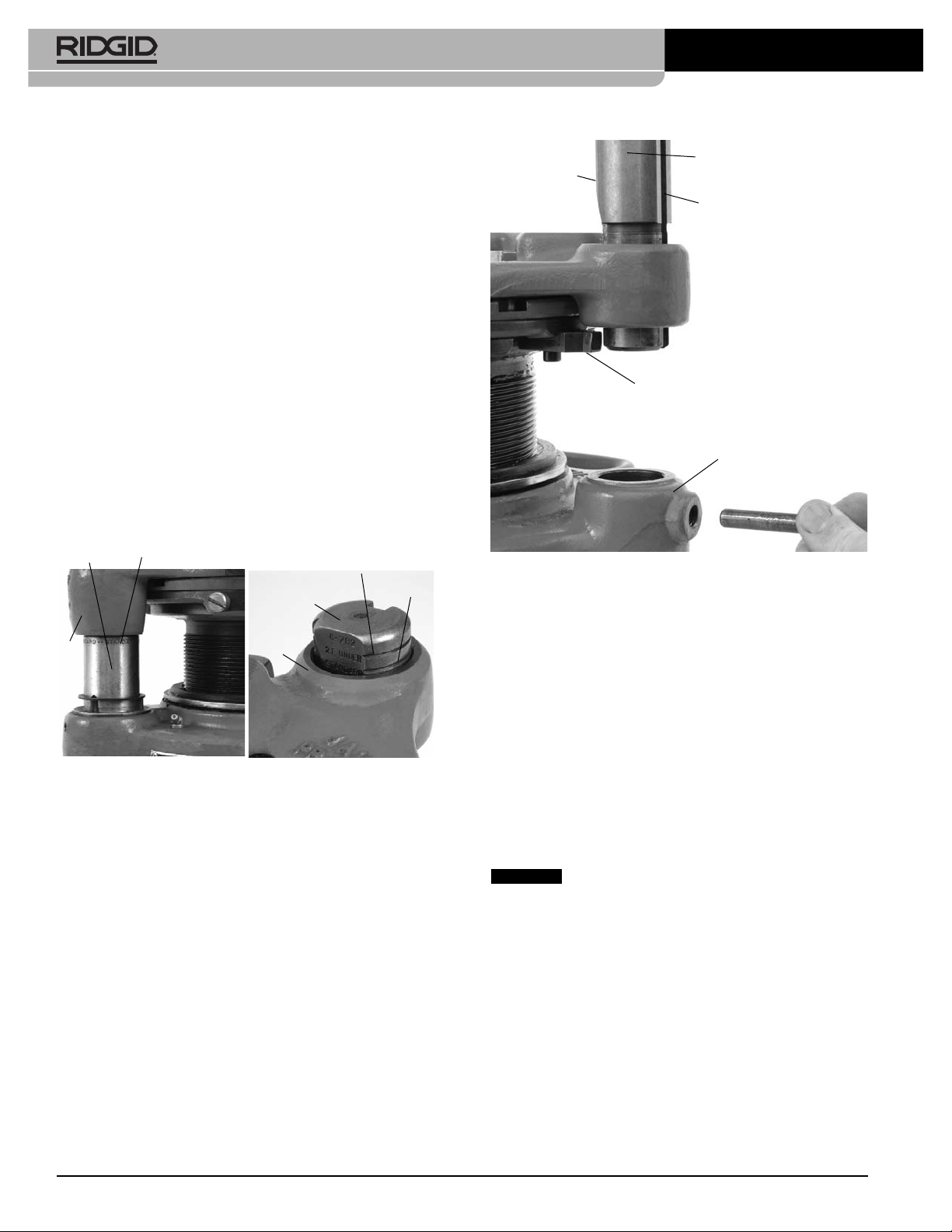
Figure 5 – Adjusting For Straight or Tapered Threads
4. Turn the guide post until appropriate slot (angled for
tapered threads, straight for straight threads) faces
inward and is aligned with the guide block.
5. Engage guide block in the guide post slot and push
the guide post down into the gear case.
6. Reinstall the screw in the gear case at the base of
guide post.
Changing Dies
Geared threaders are marked with the number of threads
per inch on the nameplate. The threaded barrel for an
NPT geared threader has 8 threads per inch, while a
BSPT geared threader has 11 threads per inch.
Do not use BSPT dies in NPT threader and
vice versa. This will cause incorrect threads and may
damage dies and/or geared threaders
1. Place the geared threader with drive shaft/die head
up.
2. Remove stop screw from the selector plate
(Figure 3)
.
3. Pull cam plate knobs out and rotate cam plate to
“CD” mark on top of the die head.
4. Remove the existing dies from the die head.
5. Insert correct dies for the application into the slots. The
numbers on the dies (1-5) must correspond with the
Thread Size Adjustment
With the drive shaft/die head of geared threader up, turn
the drive shaft or gear case by hand. Align the die head
with appropriate starting point marks on the guide post or
pinion sleeve
(see Figure 4)
. The thread size needs to be
set before every thread to insure proper thread size.
• Standard Size Thread – either set bottom of the die
head flush with the red standard line on the pinion
sleeve, or set the upper surface of die head flush
with the centerline on the guide post.
• Oversize thread (larger diameter, less turns of fitting
engagement) – set upper surface of the die head
flush with the bottom line on the guide post. That line
is marked “2T OVER”.
• Undersize thread (smaller diameter, more turns of fitting engagement) – set upper surface of the die head
flush with the top line on the guide post. That line is
marked “2T UNDER”.
Threader can be adjusted to any point in between as
desired.
Figure 4 – Thread Size Adjustment – Close-Ups of Pinion
Sleeve and Guide Post Markings
Adjusting for Straight or Tapered Threads
Geared threaders are factory set to make tapered threads
(NPT or BSPT), and can be adjusted to cut straight
threads (NPSM or BSPP). Tapered threads are made with
the guide block engaged in the angled slot in the guide
post. Straight threads are made with the guide block
engaged in the straight slot in the guide post.
1. Adjust the geared threader to cut a standard size
thread
(see above)
.
2. Remove screw from gear case at the base of guide
post.
3. Pull the guide post up until guide block (attached to
selector plate) is disengaged from the slot in the
guide post.
6
Model 141/161 Receding Geared Threaders
NOTICE
Pinion Sleeve Standard
Guide Post
2T Under
Standard
Die
Head
Die
Head
Angled Slot
Guide Post
Straight Slot
Gear Case
Guide Block
 Loading...