

Page 1

FIERY ZX
INSTALLATION AND SERVICE GUIDE
for Ricoh digital copiers
A guide for service technicians
Part Number: 10016326
Page 2

Page 3

Copyright © 1998 Electronics for Imaging, Inc. All rights reserved.
This publication is protected by copyright, and all rights are reserved. No part of it may be reproduced or transmitted in any form or by any means for any purpose without express prior
written consent from Electronics for Imaging, Inc., except as expressly permitted herein. Information in this document is subject to change without notice and does not represent a
commitment on the part of Electronics for Imaging, Inc.
The software described in this publication is furnished under license and may only be used or copied in accordance with the terms of such license.
Patents: 5,666,436; 5,553,200; 5,543,940; 5,537,516; 5,517,334; 5,506,946;5,424,754; 5,343,311; 5,212,546; 4,941,038; 4,837,722; 4,500,919
Trademarks
EFI, the EFI logo, Fiery, the Fiery logo, EFICOLOR, and Rip-While-Print are trademarks registered in the U.S. Patent and Trademark Office. Fiery ZX, Fiery LX, Fiery Driven, the Fiery
Driven logo, Command WorkStation, AutoCal, Starr Compression, Memory Multiplier, ColorWise, NetWise, and VisualCal are trademarks of Electronics for Imaging, Inc.
Adobe, the Adobe logo, Adobe Illustrator, PostScript, Adobe Photoshop, Adobe Separator, and Adobe PageMaker are trademarks of Adobe Systems Incorporated, registered in certain
jurisdictions. EPS (Encapsulated PostScript) is a trademark of Altsys Corporation. Apple, the Apple logo, AppleShare, AppleTalk, EtherTalk, LaserWriter, and Macintosh are registered
trademarks, and MultiFinder is a trademark of Apple Computer, Inc. Microsoft, MS, MS-DOS, and Windows are registered trademarks of Microsoft in the US and other countries.
QuarkXPress is a registered trademark of Quark, Inc. Times, Helvetica, and Palatino are trademarks of Linotype AG and/or its subsidiaries. ITC Avant Garde, ITC Bookman, ITC Zapf
Chancery, and ITC Z apf Dingbats ar e register ed trademarks of International Typeface Corporation. Ethernet is a registered trademark of Xero x Corporation. Farallon, PhoneNET PC, and
PhoneNET Talk are trademarks of Farallon Computing, Inc. COPS and COPSTalk are trademarks of CoOperative Printing Solutions, Inc. NetWare and Novell are r egistered trademarks
and Internetwork Packet Exchange (IPX) is a trademark of N ovell, Inc. S yQuest is a registered trademark, in the U nited States and certain other countries, of S yQuest Technology, I nc. UNIX
is a registered trademark of UNIX System Laboratories, a wholly owned subsidiary of Novell, Inc. PANTONE is a registered trademark of Pantone, Inc.
All other terms and product names may be trademarks or registered trademarks of their respective owners, and are hereby acknowledged.
Legal Notices
APPLE COMPUTER, INC. (“APPLE”) MAKES NO WARRANTIES, EXPRESS OR IMPLIED, INCLUDING WITHOUT LIMITATION THE IMPLIED WARRANTIES OF
MERCHANT ABILITY AND FITNESS FOR A P AR TICULAR PURPOSE, REGARDING THE APPLE SOFTWARE. APPLE DOES NOT W ARRANT, GUARANTEE, OR MAKE
ANY REPRESENTATIONS REGARDING THE USE OR THE RESULTS OF THE USE OF THE APPLE SOFTWARE IN TERMS OF ITS CORRECTNESS, ACCURACY,
RELIABILITY, CURRENTNESS, OR OTHER WISE. THE ENTIRE RISK AS TO THE RESULTS AND PERFORMANCE OF THE APPLE SOFTW ARE IS ASSUMED BY YOU.
THE EXCLUSION OF IMPLIED WARRANTIES IS NOT PERMITTED BY SOME STATES. THE ABOVE EXCLUSION MAY NOT APPLY TO YOU.
IN NO EVENT WILL APPLE, ITS DIRECTORS, OFFICERS, EMPL O YEES OR AGENTS BE LIABLE TO YOU FOR ANY CONSEQ UENTIAL, INCIDENT AL OR INDIRECT
DAMAGES (INCLUDING DAMAGES FOR LOSS OF BUSINESS PROFITS, BUSINESS INTERRUPTION, LOSS OF BUSINESS INFORMATION, AND THE LIKE)
ARISING OUT OF THE USE OR INABILITY TO USE THE APPLE SOFTWARE EVEN IF APPLE HAS BEEN ADVISED OF THE POSSIBILITY OF SUCH DAMAGES.
BECAUSE SOME STATES DO NOT ALLOW THE EXCLUSION OR LIMITATION OF LIABILITY FOR CONSEQUENTIAL OR INCIDENTAL DAMAGES, THE ABOVE
LIMITATIONS MAY NOT APPLY TO YOU. Apple’s liability to you for actual damages from any cause whatsoever, and regardless of the form of the action (whether in contract, tort
[including negligence], product liability or otherwise), will be limited to $50.
Restricted Rights Legends
For defense agencies: Restricted Rights Legend. Use, reproduction, or disclosure is subject to restrictions set forth in subparagraph (c)(1)(ii) of the Rights in Technical Data and Computer
Software clause at 252.227.7013.
For civilian agencies: Restricted Rights Legend. Use, reproduction, or disclosure is subject to restrictions set forth in subparagraph (a) through (d) of the commercial Computer Software
Restricted Rights clause at 52.227-19 and the limitations set forth in Electronics for Imaging, Inc.’s standard commercial agreement for this software. Unpublished rights reserved under the
copyright laws of the United States.
Printed in the United States of America on recycled paper.
FCC Information
WARNING: FCC Regulations state that any unauthorized changes or modifications to this equipment not expr essly approved b y the manufacturer could void the user’s authority to operate
this equipment.
NOTE: This equipment has been tested and found to comply with the limits for a Class A digital device, pursuant to P art 15 of the FCC Rules. These limits are designed to provide reasonable
protection against harmful interference when the equipment is operated in a commercial environment. This equipment generates, and uses, and can radiate radio frequency energy and, if
not installed and used in accordance with the instruction manual, may cause harmful interference to radio communications. Operation of this equipment in a residential area is likely to
cause interference in which case the user will be required to correct the interference at his own expense.
Industry Canada Class A Notice
This digital apparatus does not exceed the Class A limits for radio noise emissions from digital apparatus as set out in the interference-causing equipment standard entitled, “Digital
Apparatus” ICES-003 from Industry Canada.
Avis de Conformation Classe A d l’Industrie Canada
Le présent appareil numérique n’émet pas de bruits radioélectriques dépassant les limites applicables aux appareils numériques de la Classe A prescrites dans la norme sur le matériel brouilleur ,
“Appareils Numériques” NMB-003 édictée par l’Industrie Canada.
Certificate by Manufacturer/Importer
This is to certify that the FC07 is shielded against radio interference in accordance with the provisions of VFG 243/1991. The G erman Postal Services have been advised that this device is
being put on the market and that they have been given the right to inspect the series for compliance with the regulations.
Electronics for Imaging, Inc.
Page 4

Bescheinigung des Herstellers/Importeurs
Heirmit wird bescheinigt, dass der FC07 im Uebereinstimmung mit den Bestimmungen der VFG 243/1991 Funk-Entstort ist. Der Deutschen Bundespost wurde das Inverkehrbringen
dieses Geraetes angezeigt und die Berechtigung zur Ueberpruefung der Serie auf Einhaltung der Bestimmungen eingeraumt.
Electronics for Imaging, Inc.
RFI Compliance Notice
This equipment has been tested concerning compliance with the relevant RFI protection requirements both individually and on system level (to simulate normal operation conditions).
However , it is possible that these RFI R equir ements are not met under certain unfavorable conditions in other installations. It is the user who is responsible for compliance of his particular
installation.
Dieses Geraet wurde einzeln sowohl als auch in einer Anlage, die einen normalen Anwendungsfall nachbildet, auf die Einhaltung der Funk-entstoerbestimmungen geprueft. Es ist jedoch
moeglich, dass die Funk-enstoerbestimmungen unter unguenstigen Umstaenden bei anderen Geraetekombinationen nicht eingehalten werden. Fuer die Einhaltung der Funkentstoerbestimmungen seigner gesamten Anlage, in der dieses Geraet betrieben wird, ist der Betreiber verantwortlich.
Compliance with applicable regulations depends on the use of shielded cables. It is the user who is responsible for procuring the appropriate cables.
Einhaltung mit betreffenden Bestimmungen kommt darauf an, dass geschirmte Ausfuhrungen gebraucht werden. Fuer die beschaffung richtiger Ausfuhrungen ist der Betreiber
verantwortlich.
Software License Agreement
Before using the Software, please carefully read the following terms and conditions. BY USING THIS SOFTWARE, Y OU SIGNIFY THAT YOU HAVE A CCEPTED THE TERMS OF
THIS AGREEMENT. If you cannot or do not accept these terms, you may return the entire package within ten (10) days to the Distributor or Dealer from which you obtained them for
a full refund.
Electronics for Imaging, Inc. grants to you a non-exclusive, non-transferable license to use the software and accompanying documentation (“Software ”) included with the F iery ZX you have
purchased, including without limitation the PostScript
®
software provided by Adobe Systems Incorporated.
You may:
a. use the Software solely for your own customary business purposes and solely with Fiery ZX;
b. use the digitally-encoded machine-readable outline and bitmap programs (“Font P rograms ”) provided with F iery ZX in a special encrypted format (“Coded Font Programs ”) to r eproduce
and display designs, styles, weights, and versions of letters, numerals, characters and symbols (“Typefaces”) solely for your own customary business purposes on the display window of the
Fiery ZX or monitor used with Fiery ZX;
c. use the trademarks used by Electronics for Imaging to identify the Coded Font Programs and Typefaces reproduced therefrom (“Trademarks”); and
d. assign your rights under this Agreement to a transferee of all of your right, title and interest in and to Fiery ZX provided the transferee agrees to be bound by all of the terms and conditions
of this Agreement.
You may not:
a. make use of the Software, directly or indirectly, to print bitmap images with print resolutions of 600720 dots per inch or greater, or to generate fonts or typefaces for use other than with
Fiery ZX;
b. make or have made, or permit to be made, any copies of the Software, Coded Font Programs, accompanying documentation or portions thereof, except as necessary for use with the
Fiery ZX unit purchased by you; provided, however, that under no cir cumstances may you make or have made, or permit to be made, any copies of that certain portion of the Software which
has been included on the Fiery ZX hard disk drive. You may not copy the documentation;
c. attempt to alter, disassemble, decrypt or reverse engineer the Software, Coded Font Programs or accompanying documentation.
d. rent or lease the Software.
Proprietary Rights
You acknowledge that the Software, Coded Font Programs, Typefaces, Trademarks and accompanying documentation are proprietary to Electronics for Imaging and its suppliers and that
title and other intellectual property rights therein remain with Electronics for Imaging and its suppliers. Except as stated above, this Agreement does not grant you any right to patents,
copyrights, trade secrets, trademarks (whether registered or unregistered), or any other rights, franchises or licenses in respect of the Software, Coded Font Programs, T ypefaces, Trademarks
or accompanying documentation. You may not adapt or use any trademark or trade name which is likely to be similar to or confusing with that of Electronics for Imaging or any of its
suppliers or take any other action which impairs or reduces the trademark rights of Electronics for Imaging or its suppliers. The trademarks may only be used to identify printed output
produced by the Coded Font Programs. At the reasonable request of Electronics for Imaging, you must supply samples of any Typeface identified with a trademark.
Confidentiality
You agree to hold the Software and Coded Font Programs in confidence, disclosing the Software and Coded Font Programs only to authorized users having a need to use the Software and
Coded Font Programs as permitted by this Agreement and to take all reasonable precautions to prevent disclosure to other parties.
Remedies
Unauthorized use, copying or disclosure of the Software, Coded F ont Programs, Typefaces, Trademarks or accompanying documentation will result in automatic termination of this license
and will make available to Electronics for Imaging other legal remedies.
Limited Warranty And Disclaimer
Electronics for Imaging warrants that, for a period of ninety (90) days from the date of delivery to you, the Software under normal use will perform without significant errors that make it
unusable. Electronics for Imaging’s entire liability and your exclusive remedy under this warranty (which is subject to you returning Fiery ZX to Electronics for Imaging or an authorized
dealer) will be, at Electronics for Imaging’s option, to use reasonable commercial efforts to attempt to correct or work around errors, to replace the Software with functionally equivalent
software, or to refund the purchase price and terminate this Agreement. Some states do not allow limitations on duration of implied warranty, so the above limitation may not apply to you.
Except for the above express limited warranty, Electronics for Imaging makes and you receive no warranties or conditions on the Products, express, implied, or statutory, and E lectronics for
Imaging specifically disclaims any implied warranty or condition of merchantability or fitness for a particular purpose.
Page 5

For warranty service, please contact your authorized service/support center.
EXCEPT FOR THE ABOVE EXPRESS LIMITED WARRANTY, ELECTRONICS FOR IMAGING MAKES AND YOU RECEIVE NO WARRANTIES OR CONDITIONS ON
THE SOFTWARE OR CODED FONT PR OGRAMS, EXPRESS, IMPLIED, ST A TUTOR Y , OR IN ANY OTHER PR OVISION OF THIS AGREEMENT OR COMMUNICA TION
WITH YOU, AND ELECTRONICS FOR IMAGING SPECIFICALLY DISCLAIMS ANY IMPLIED WARRANTY OR CONDITION OF MERCHANTABILITY OR FITNESS
FOR A PARTICULAR PURPOSE. Electronics for I maging does not warrant that the operation of the software will be uninterrupted or error free or that the Software will meet your specific
requirements.
Limitation Of Liability
IN NO EVENT WILL ELECTRONICS FOR IMAGING OR ITS SUPPLIERS BE LIABLE FOR ANY DAMAGES, INCLUDING LOSS OF DATA, LOST PROFITS, COST OF
COVER OR OTHER SPECIAL, INCIDENTAL, CONSEQUENTIAL OR INDIRECT DAMAGES ARISING FROM THE USE OF THE SOFTWARE, CODED FONT
PROGRAMS OR ACCOMPANYING DOCUMENTATION, HOWEVER CAUSED AND ON ANY THEORY OF LIABILITY. THIS LIMITATION WILL APPLY EVEN IF
ELECTRONICS FOR IMAGING OR ANY AUTHORIZED DEALER HAS BEEN ADVISED OF THE POSSIBILITY OF SUCH DAMAGE. YOU ACKNOWLEDGE THAT THE
PRICE OF THE UNIT REFLECTS THIS ALLOCATION OF RISK. BECAUSE SOME STA TES/JURISDICTIONS DO NOT ALLOW THE EXCLUSION OR LIMITATION OF
LIABILITY FOR CONSEQUENTIAL OR INCIDENTAL DAMAGES, THE ABOVE LIMITATION MAY NOT APPLY TO YOU.
Export Controls
You agree that you will not export or re-export the Software or Coded Font Programs in any form without the appropriate United States and foreign government licenses. Your failure to
comply with this provision is a material breach of this Agreement.
Government Use
Use, duplication or disclosure of the Software by the U nited S tates Go vernment is subject to r estrictions as set forth in subdivision (c) (1) (ii) of the Rights in Technical Data and Computer
Software clause at DFARS 252.227-7013 or in subparagraphs (c) (1) and (2) of the Commercial Computer Software—Restricted Right Clause at 48 CFR 52.227-19, as applicable.
Third Party Beneficiary
You are hereby notified that Adobe Systems Incorporated, a California corporation located at 345 Park Avenue, San Jose, CA 95110-2704 (“Adobe”) is a third-party beneficiary to this
Agreement to the extent that this Agreement contains provisions which relate to your use of the Fonts, the Coded Font Programs, the Typefaces and the Trademarks licensed hereby. Such
provisions are made expressly for the benefit of Adobe and are enforceable by Adobe in addition to Electronics for Imaging.
General
This Agreement will be governed by the laws of the State of California.
This Agreement is the entire agreement held between us and supersedes any other communications or advertising with respect to the Software, Coded Font Programs and accompanying
documentation.
If any provision of this Agreement is held invalid, the remainder of this Agreement shall continue in full force and effect.
If you have any questions concerning this Agreement, please write to Electronics for Imaging, Inc., Attn: Licensing Dept. or see Electronics for Imaging’s web site at www.efi.com.
Electronics for Imaging, Inc.
2855 Campus Drive
San Mateo, CA 94403
Page 6

Page 7

Contents
Preface
About this guide
About the illustrations in this guide xi
Terminology and conventions xii
Precautions
Tools you will need
Chapter 1: Introduction
Features
How the Fiery ZX operates
Fiery ZX print options
User software
Fiery WebTools 1-5
Chapter 2: Preparing for Fiery ZX Installation
Installation sequence
Checking the customer site
Setting customer expectations 2-4
Unpacking the Fiery ZX
Fiery ZX panels
xi
xiii
xv
1-1
1-2
1-3
1-4
2-1
2-3
2-5
2-7
Chapter 3: Connecting the Fiery ZX
Preliminary checkout
Connecting to the copier
Verifying the connection
Printing the Fiery ZX Test Page 3-5
Checking scanning and printing 3-6
Installing additional options
Connecting to the network
Ethernet network connections 3-8
Connecting a PC-compatible to the Fiery ZX
Using the Control Panel
Activity light 3-14
Buttons 3-14
Control Panel screens and icons 3-15
Shutting down and restarting the Fiery ZX
3-1
3-3
3-5
3-7
3-7
3-11
3-13
3-20
vii
Page 8

Contents
Chapter 4: Service Procedures
Overview
System software service 4-1
Accessing Fiery ZX internal components
Accessing front panel components
Checking Fiery ZX internal connections
Restoring Fiery ZX functionality after service 4-11
Removing and replacing circuit boards
MXV board 4-13
Video interface board 4-15
STARR daughter card 4-17
User interface board 4-20
Motherboard
Removing the Fiery ZX motherboard 4-24
Replacing the motherboard 4-27
Replacing parts on the motherboard 4-28
Motherboard jumpers 4-32
HDD backplane board
Fans
Back panel fan 4-36
CPU fan 4-37
Power supply
Checking voltages 4-38
Removing and replacing the power supply 4-39
Hard disk drive
CD-ROM drive
Front panel components
Jewels 4-48
Buttons 4-48
Fiery ZX system software
4-1
4-3
4-6
4-8
4-13
4-23
4-34
4-36
4-37
4-40
4-45
4-47
4-49
viii
Page 9

Contents
Chapter 5: Troubleshooting
The troubleshooting process
Where problems occur
Before you go to the customer site
Preliminary on-site checkout
Checking the interface cables 5-5
Checking the internal components 5-6
Checking the Fiery ZX as a stand-alone unit
Isolating the Fiery ZX 5-8
Errors and beep codes during startup diagnostics 5-9
General Fiery ZX system error conditions 5-13
Viewing the diagnostic Info screen 5-15
Video interface board diagnostics 5-16
Checking the entire Fiery ZX system
Checking the copier interface 5-18
Checking network connections
Printing to the Fiery ZX 5-22
Appendix A: Specifications
Hardware features
Networking and connectivity
User software
Safety and emissions compliance
5-1
5-2
5-3
5-4
5-8
5-18
5-21
A-1
A-1
A-1
A-1
Index
ix
Page 10

Page 11

About this guide
Preface
The Installation and Service Guide is intended for certified Fiery ZX
™
and copier service
technicians installing or servicing a Fiery ZX Color Server. If you have not received
installation and service certification, you should not attempt to install or service a
Fiery ZX Color Server. E lectronics for I maging, Inc. does not warrant the performance if
installed or serviced by non-certified personnel.
About this guide
This guide covers the following topics:
• “Preface”
General information about this guide and about installing the Fiery ZX
• Chapter 1, “Introduction”
General information about the Fiery ZX
• Chapter 2, “Preparing for Fiery ZX Installation”
Unpacking and the steps you need to take before you install the unit
• Chapter 3, “Connecting the Fiery ZX”
How to connect the Fiery ZX to the copier and the network and verify that the system
is working correctly; overview of the Control Panel
• Chapter 4, “Service Procedures”
Removal and replacement procedures for Fiery ZX components
• Chapter 5, “Troubleshooting”
Common problems and ways of correcting them; startup error codes
• The Configuration Guide is also provided under separate cover at the back of this
manual. It provides information on the different network environments and how to
configure Fiery ZX Setup options.
OTE
N
:
Fiery ZX customers should not use the technical service documentation. Please
don ’t leave your copy of the Installation and Service Guide behind after you make a service
call.
About the illustrations in this guide
The illustrations in this guide reflect the current shipping version of the Fiery ZX at the
time of publication. Components shown in these illustrations are subject to change. To
receive information about any Fiery ZX components that do not match the illustrations
in this guide, contact your authorized service/support center.
xi
Page 12

Preface
Terminology and conventions
The term “Fiery ZX” is used throughout this manual to refer to both Fiery ZX3200 and
Fiery ZX3300. Fiery ZX3200 models have a standard memory configuration of 160MB;
Fiery ZX3300 models have a standard memory configuration of 256MB.
The term “ network administrator” refers to the person responsible for maintaining the
network at the customer site.
The term “Control Panel” refers to the area on the front of the Fiery ZX including the
green/red activity light, the display window (LCD—liquid crystal display), and the
buttons to the right of and below the display window.
The term “system software” refers to the software installed on the Fiery ZX hard disk
drive.
The term “PC-compatible” refers to any device that may be connected to the Fiery ZX
for parallel printing.
The term “100BaseT” is used throughout this manual to refer to 100BaseTX.
References to other Fiery ZX manuals, such as the Configuration Guide, are displayed in
italics.
OTE
N
:
The note format highlights important messages and additional information.
The caution icon indicates a need for special care and safety when handling the
!
equipment.
Fiery ZX Control Panel screen messages and commands referred to in the text of this
manual appear in the
Officina Sans
typeface.
xii
Page 13

Precautions
Precautions
Always observe the following general precautions when installing and servicing the
Fiery ZX:
1. Report any shipping damage.
If there is any evidence of shipping or handling damage to the Fiery ZX packing boxes or
their contents, save the damaged boxes and parts, call the shipper immediately to file a
claim, and notify your authorized service/support center.
2. Never alter an existing network without permission.
The Fiery ZX will probably be connected to an existing Local Area Network (LAN)
based on Ethernet hardware. The network is the link between the customer’s computer,
existing laser printers, and other prepress equipment. Never disturb the LAN by breaking
or making a network connection, altering termination, installing or removing
networking hardware or software, or shutting down networked devices without the
knowledge and express permission of the system or network administrator or the shop
supervisor.
3. Never enter an IP address in Fiery ZX Network Setup.
Only the network administrator should enter an IP address on a network device.
Assigning the Fiery ZX an incorrect IP address may cause unpredictable errors on any or
all devices connected to the network.
4. Always disconnect power before opening the Fiery ZX.
Although Fiery ZX circuitry operates on 5V DC and 12V DC, 115V AC is present when
the cover is removed. Before you service the Fiery ZX, shut it down completely and
unplug the AC power cable from the back of the Fiery ZX.
5. Handle the Fiery ZX Control Panel display window with care.
The Fiery ZX display window is made of glass. If the glass breaks and the liquid crystal
inside leaks out, avoid contact with it. If you do come in contact with the liquid crystal,
wash it off with soap and water immediately.
6. Avoid pressing the surface of the display window.
Applying pressure to the display window will cause it to change color.
7. Use a soft cloth moistened with isopropyl or ethyl alcohol to clean the surface of the
Fiery ZX display window.
Other solvents, such as water, may damage the polarizer on the display window.
xiii
Page 14

Preface
8. Use care when handling parts of the Fiery ZX as some edges on the unit may be sharp.
For example, be careful when:
• Accessing the CD-ROM drive (keep the drive door closed when not in use)
• Plugging in cables at the back of the unit
• Using the power switch to power on/off the unit
9. Follow standard ESD (electrostatic discharge) precautions while working on the internal
components of the Fiery ZX.
Static is always a concern when servicing electronic devices. It is highly unlikely that the
area around the copier and the Fiery ZX is static-free. Carpeting, leather-soled shoes,
synthetic clothing fibers, silks, and plastics may generate a static charge of more than
10,000 volts. Static discharge is capable of destroying the circuits etched in silicon
microchips, or dramatically shortening their life span. By observing standard precautions,
you may avoid extra service calls and save the cost of a new board.
When possible, work on a ground-connected antistatic mat. Wear an antistatic
grounding strap, grounded at the same place as the antistatic mat. If that is not possible:
• Attach a grounding strap to your wrist. Attach the other end to a good ground.
• When you unpack the Fiery ZX from the carton for the first time, touch a metal area
of the copier to discharge the static on your body.
• Before you remove the Fiery ZX side panel and before you handle internal
components, touch a metal part of the Fiery ZX.
• Leave new electronic components inside their antistatic bags until you are ready to
install them. When you remove components from an antistatic bag, place them on a
grounded antistatic surface, component-side up.
• When you remove an electronic component, place it into an antistatic bag
immediately. Do not walk across a carpet or vinyl floor while carrying an unprotected
board.
10. Handle printed circuit boards by their edges only, but avoid touching the contacts on the
edge of the board.
11. Never set a cup of coffee—or any liquid—on or near the Fiery ZX or the copier.
xiv
Page 15

Tools you will need
Tools you will need
To install or service the Fiery ZX, you should bring the following tools and parts:
• ESD wrist grounding strap and antistatic mat
• Wire cutters
• #0 and #1 Phillips head screwdrivers (non-magnetic)
• 3/16" hex nut driver
• Flashlight
You should also bring this guide and any technical notes for the Fiery ZX.
xv
Page 16

Page 17
Features
Chapter 1:
Introduction
1
The Fiery ZX Color Server adds computer connectivity and highly efficient Adobe
PostScript 3 color printing capacity to color copiers. It is optimized for high-speed
network communications, processing, rasterization, and printing of continuous tone
color and monochrome pages.
Features
The Fiery ZX, as an integral part of a color printing system, enables users of PCcompatibles, Mac OS computers, and UNIX workstations to:
• Send images over AppleTalk, TCP/IP, and Novell networks to print on Fiery ZX
supported devices.
• Spool print jobs and select a printing priority for each job. Users can control spooled
print jobs sent to the Fiery ZX with remote utility software running on networked PCcompatible and Mac OS computers.
• Print files, in color, grayscale, and black and white.
• Use the copier as a high-resolution color scanner with Fiery Scan software.
• Use 136 resident fonts (117 Adobe Type 1 PostScript, and 19 TrueType), plus two
Adobe Multiple Master fonts used for font substitution when printing PDF files.
The Fiery Downloader or any third-party LaserWriter downloader, such as the Adobe
Font Downloader, can be used to download additional fonts.
• Use built-in ColorWise
Copier
™
color management and NetWise
™
network features.
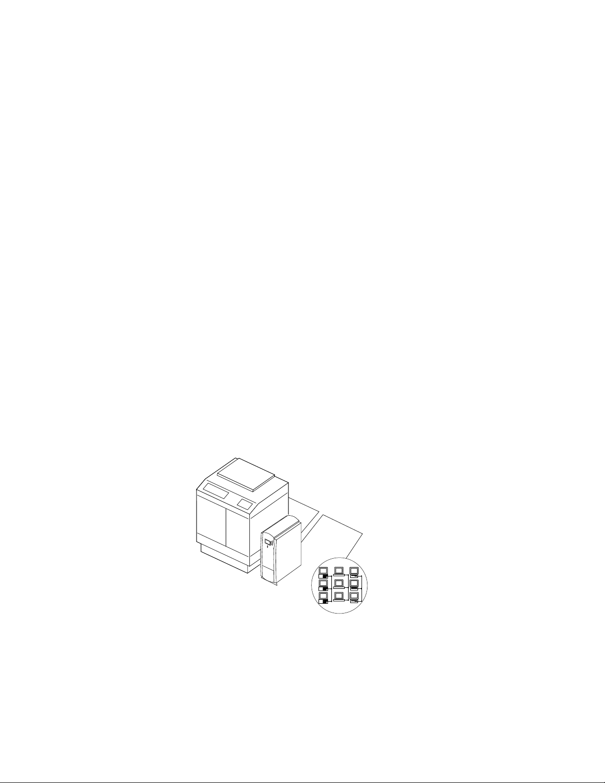
Fiery ZX
Networked computers
or workstations
F
1-1
IGURE
The Fiery ZX is one of several imaging products engineered and manufactured by
Electronics for Imaging, Inc.
Fiery ZX printing system
1-1
Page 18

Introduction
1
How the Fiery ZX operates
The Fiery ZX enables the customer to use a color copier as a printer and scanner. Users
can print to the Fiery ZX from networked PC-compatibles running Microsoft Windows,
from networked Mac OS computers, and from networked UNIX workstations running
TCP/IP. In addition, the Fiery ZX parallel port can be used to print directly from a PCcompatible.
The Fiery ZX custom-designed boards and system software are responsible for efficient
image processing and printing controls. The main functions of Fiery ZX components
and software are described below.
The Fiery ZX uses specialized circuit boards, the motherboard and the video interface
board, to process image data for printing and scanning images.
The motherboard includes an Alpha 21164 533MHz CPU chip which controls the
image data transfer to and from the video interface board and runs the PostScript
interpreter. The PostScript interpreter rasterizes the PostScript page description file and
then compresses the image pattern into memory using compression technology.
The PostScript interpreter outputs compressed raster data through the image frame
buffer memory to the Fiery ZX STARR daughter card installed on the video interface
board. The STARR daughter card decompresses the image data and sends it to the copier
through the video interface board and the copier interface cable. The raster data supplied
to the laser in the copier charges the drum and renders the final image on paper at full
copier engine speed.
High-speed DIMMs (dual in-line memory modules) on the motherboard hold the image
data during printing. The Fiery ZX is configured with 160MB or 256MB of memory.
™
When Fiery Scan
and blue) image data from the copier, stores it in memory, and transmits it to the
computer that requested the scan.
uses the copier as a scanner, the Fiery ZX acquires RGB (red, green,
1-2
Page 19
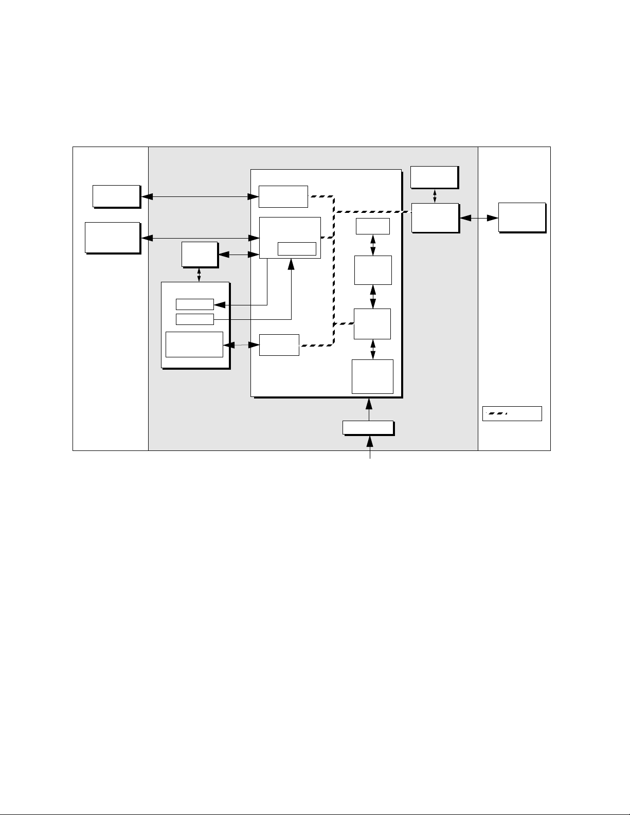
Fiery ZX print options
1
External Devices CopierFiery ZX
Networked
computers
Parallel Devices
(Input/Output)
User
interface
board
HDD backplane
Speaker
Reset
Hard disk drive
and
CD-ROM drive
Network
interface
I/O Control
Flash ROM
SCSI
interface
Motherboard
Cache
CPU
PCI/
Memory
Controller
Memory
PostScript
interpreter
MXV
board
Video
interface
board
&
Print/Scan
Copier
PCI Bus
Power supply
AC power
IGURE 1-2 Fiery ZX functional diagram
F
+3.3/+5/±12VDC
Fiery ZX print options
The Fiery ZX’s efficient capabilities allow users to use a variety of applications to create
and print pages of text and/or images. The Fiery ZX operates over a network or through
the parallel port.
Printing over a network allows Fiery ZX users to print documents directly from
applications in which they were created. In addition, the F iery ZX offers an efficient way
to print files that have been saved in PostScript, EPS (Encapsulated PostScript), or PDF
(Portable Document Format). These files can be downloaded directly to the Fiery ZX
using the Fiery Downloader™, one of the remote utilities for use with the Fiery ZX.
In addition, customers can print documents directly from applications running on a PCcompatible connected to the Fiery ZX parallel port. PostScript files can also be printed to
the parallel port from Windows, including the MS-DOS window.
1-3
Page 20

Introduction
1
User software
Fiery ZX user software is provided on the User Software CD and the Command
WorkStation CD. Some of the software can also be installed from the Fiery WebTools
Installer (see Getting Started for more information on WebTools). The network
administrator or user at the customer site is responsible for installing software onto
computers that will use the Fiery ZX over the network.
The following user software is included:
Adobe PS Printer Driver Enables users to print to the Fiery ZX from
PC-compatible and Mac OS computers; also
supports special Fiery ZX print features and
PostScript 3 features.
PostScript Printer Description
file (PPD)
PostScript Screen Fonts Screen fonts for the 136 PostScript printer fonts
Fiery Downloader
Fiery Print Calibrator
™
™
File for use with the PS printer driver that allows the
Fiery ZX to appear in popular applications’ Print and
Page Setup dialog boxes. The PPD provides
information about the Fiery ZX and the particular
copier model to the application and printer driver
being used.
installed on the Fiery ZX (117 Adobe Type 1 and 19
TrueType). See the Printing Guide for a complete list.
Enables users to print PostScript files, EPS
(Encapsulated PostScript) files, and PDF (Portable
Document Format) files directly to the Fiery ZX
without opening the application in which they were
created. The Fiery Downloader also enables users to
manage the printer fonts installed on the Fiery ZX.
Fiery Downloader is also installed with the
Command W or kS tation software.
Enables users to calibrate the Fiery ZX remotely from
their computer. Proper calibration keeps color
consistent across time and from job to job.
1-4
Fiery Print Calibrator is also installed with the
Command W or kS tation software.
Page 21

User software
1
Fiery Spooler
Fiery Scan™ Plug-in A TWAIN plug-in module for Photoshop that
For Fiery ZX3300,
Command W or kS tation (on
Command W or kS tation CD)
Color management files ColorSync and ICM color management files that
Color reference files Reference pages that users can print to view the range
Fiery WebTools
The Fiery ZX can support Internet or intranet access with Fiery WebTools, which
include Status, WebSpooler, Installer, and W ebLink. For mor e information on WebT ools,
see the Configuration Guide and Getting Started.
™
Enables users to view the order and priority of print
jobs, customize printer settings for jobs, delete jobs,
and move jobs between queues. Users can also view
job accounting information.
enables users to scan images from the copier directly
into Photoshop.
Enables users to run the Command WorkStation
application from a remote workstation. For more
information on using the Command WorkStation,
see the Job Management Guide.
enable users to maintain consistent color from the
original artwork to the colors displayed on the
monitor to the printed output.
of colors available on the Fiery ZX.
1-5
Page 22

Page 23

Installation sequence
Chapter 2:
Preparing for
Fiery ZX
Installation
2
This chapter includes the following information:
• Summary of the installation sequence
• Checking the customer site
• Unpacking the Fiery ZX
• Fiery ZX front and back overview
Installation sequence
Familiarize yourself with Chapters 2 and 3 of this guide before you attempt an
installation. The installation sequence described in this chapter is designed to make your
job as easy as possible. Installation problems are easier to avoid and diagnose if you
proceed from the component to the system level and verify functionality at each stage.
Figure 2-1 on page 2-2 outlines the recommended installation procedure for connecting
the Fiery ZX to the copier.
Because the Fiery ZX is a node on the customer’s computer network, make sure that you
coordinate your scheduled installation with the network administrator at the customer
site. Refer the network administrator to the Configuration Guide for network setup
information.
2-1
Page 24
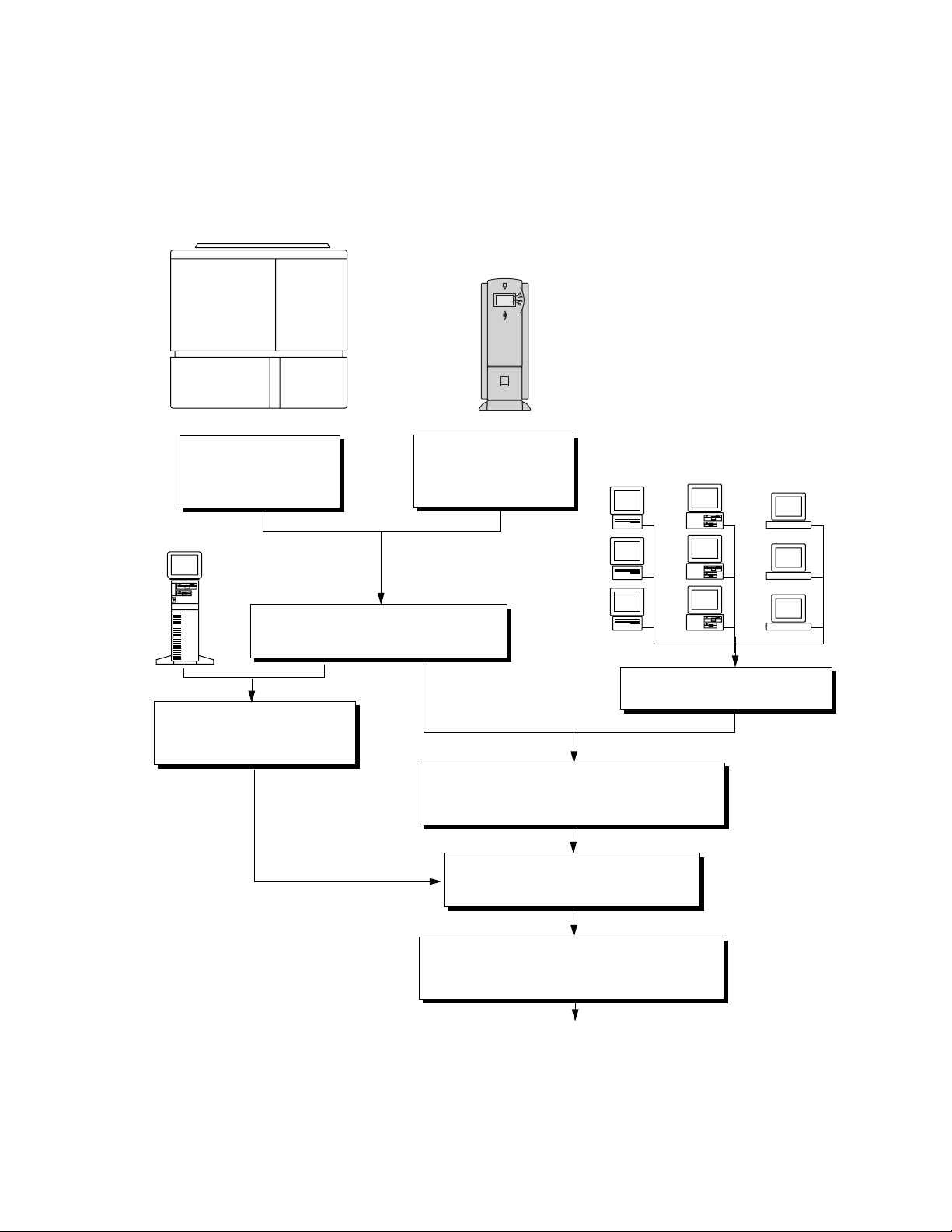
2
Copier
Preparing for Fiery ZX Installation
Fiery ZX
Check installation
requirements and verify site
conditions, page 2-3
compatible
PC
-
Connect copier interface cable, page 3-3
Connect PC-compatible to the
parallel port of the Fiery ZX,
page 3-11
Unpack the Fiery ZX,
Initial startup, page 3-1
Print a Fiery ZX Test Page, page 3-5
Network administrator connects the Fiery ZX to the
network and verifies the connection (see page 3-7 and
page 2-5
Configuration Guide )
the
Network administrator configures Setup
options (see the
Configuration Guide )
Mac OS
computers
Verify network operation with out the
PC-compatible
computers
Fiery ZX connected.
workstations
UNIX
2-2
Network administrator installs Fiery ZX user software
on networked computers that print to the Fiery ZX (see
Getting Started )
Full Fiery ZX functionality
IGURE 2-1 Recommended installation steps and references
F
Page 25

2
❑
❑
❑
Checking the customer site
Checking the customer site
Before you install the Fiery ZX, check site conditions and inform the customer of any
installation requirements.
Copier model
What copier model is installed?
Is there space near the copier for the Fiery ZX?
Make sure that there is space for the Fiery ZX. You may need to move the copier out
from the wall for easier access to the connectors.
Does the copier require service or adjustments?
Copy the copier color test page before you install the Fiery ZX.
If the copied image indicates that the copier needs adjustment, inform the customer.
After getting approval, complete the copier service needed.
Power
❑
Is there a dedicated grounded electrical outlet near the copier for the Fiery ZX?
Locate the grounded electrical outlet that will supply power to the Fiery ZX. You should
not run the Fiery ZX and the copier on the same circuit. Use a surge suppressor for the
Fiery ZX.
• Do not use a 3-prong adapter in a 2-hole ungrounded outlet.
• Do not use an extension cord.
• Do not plug the Fiery ZX into a circuit with heating or refrigeration equipment
(including water coolers).
• Do not plug the Fiery ZX into a switchable wall outlet. This can result in the Fiery ZX
being turned off accidentally.
Network
❑
What is the network cable and connection type?
• Thinnet (10Base2)—Is an Ethernet transceiver available?
• Thicknet (10Base5)
• Unshielded twisted pair (10BaseT/100BaseT)
• Did the customer order the Token Ring network option?
2-3
Page 26

Preparing for Fiery ZX Installation
2
❑
Is the network connection ready and tested for Fiery ZX installation?
To verify that the network is functioning before you attach the Fiery ZX:
• Ask the network administrator to print a document on a shared printer over the
• Ask the network administrator to verify the computer and network requirements as
Parallel port
❑
Is there room for both the Fiery ZX and the PC-compatible that will be connected to the
Fiery ZX?
System contact person
Will the person responsible for the computers and the network be available at the time
❑
set for installation? Get a name as a contact.
network.
specified in Getting Started .
Setting customer expectations
If the site is ready, installation takes about one hour. The customer should be informed of
the following:
• The network may be unavailable for up to one hour.
• The equipment may be unavailable for up to one hour.
• The network administrator needs to be available during the installation for network
connectivity.
Equipment downtime and impact on the network can be minimized if the network
administrator installs a network connector for the Fiery ZX and confirms network
functionality with the connector in place before the date scheduled for the Fiery ZX
installation.
• The network administrator should have a networked computer available during the
installation. The appropriate software should already be installed. Documentation for
the networked computer and the network operating software should be available.
• The network administrator should install the user software shipped with the Fiery ZX
(user documentation is also included) onto networked PC-compatible and Mac OS
computers that will print to the Fiery ZX.
N
:
OTE
This guide covers Fiery ZX hardware installation and service. It provides general
information on connecting the Fiery ZX to the customer’s network. Network setup and
configuration information goes beyond the scope of this guide. For network setup and
configuration information, the network administrator should use the Configuration
Guide .
2-4
Page 27

2
O
UNPACK
T
Unpacking the Fiery ZX
Unpacking the Fiery ZX
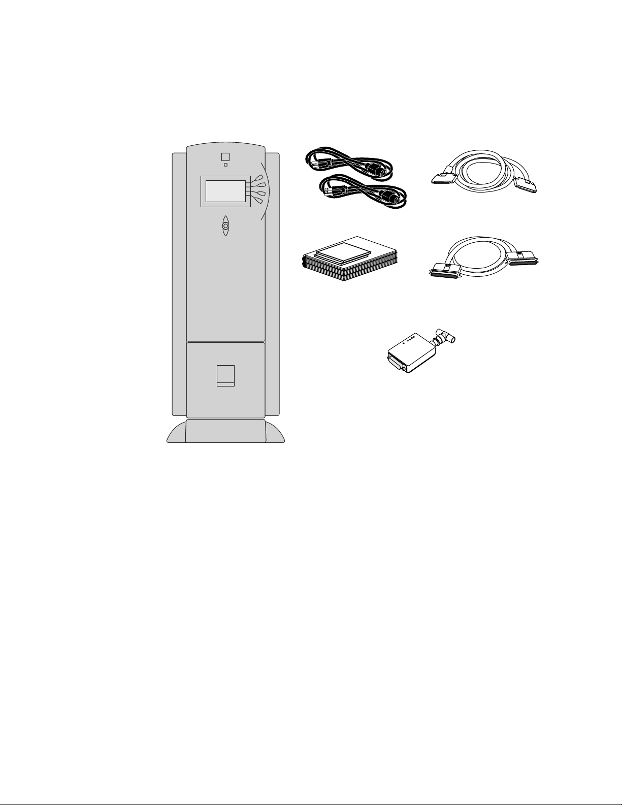
The Fiery ZX is assembled and shipped from the factory in a box that includes all
necessary cables and documentation, as shown in Figure 2-2 on page 2-6.
THE
IERY
F
Save the original boxes and packing materials. If you need to transport the Fiery ZX at a
later date, the original box and packing material will ensure safe shipment.
1. Open the Fiery ZX Color Server box and remove the packing material.
2. Remove the contents from the top container. Inspect the contents for visible damage.
The top container should include the following items:
• Bags containing the copier interface cable (16' long with 100-pin D connectors),
parallel cable, and two AC power cables (US and Europe).
ZX
• AUI to BNC Ethernet Transceiver
• Media package (includes a package of user documentation, and the User Softwar e CD)
Fiery ZX3300 systems also include the Command WorkStation CD.
OTE
A service kit containing the System Software CD is provided separately.
N
:
3. Give the media package to the customer or the network administrator.
Let the customer or network administrator know that in order to take full advantage of
the Fiery ZX, the user software must be installed on computers that will print to the
Fiery ZX.
4. Set aside the remaining components from the top container.
5. Remove the top container and any packing materials. Set aside the packing material in
case you need to reship the unit.
6. Carefully lift the Fiery ZX out of the box.
If you notice shipping damage to any Fiery ZX component, be sure to save the shipping
container in case the carrier needs to see it. Call the carrier immediately to report the
damage and file a claim, then call your authorized service/support center. Be ready to
furnish the serial number, printed on the back of the Fiery ZX.
2-5
Page 28
Preparing for Fiery ZX Installation
2
IGURE
F
Fiery ZX
2-2
Fiery ZX power cables
Media Package
Ethernet transceiver
Contents of Fiery ZX shipping box
Copier interface cable (100-pin)
Parallel cable (25-pin)
2-6
Page 29
Fiery ZX panels
2
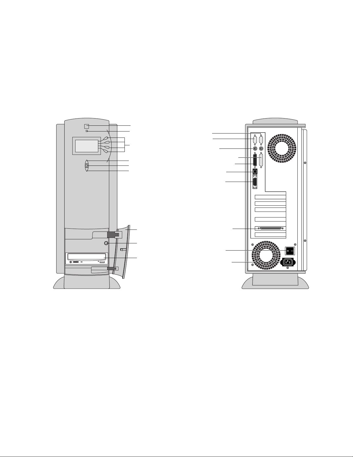
Fiery ZX panels
Once you have unpacked the Fiery ZX, you can familiarize yourself with the front and
back of the Fiery ZX before you install it.
Jewel
Activity light
Line selection
buttons
Up button
Menu button
Down button
Drive door
Reset button
CD-ROM drive
Serial ports:
COM1
COM2
Not used
Parallel port (LPT1)
Future use (LPT0)
10/100BaseT
AUI Ethernet
Copier interface
connector
Power switch
Power connector
Front panel
F
IGURE
Front and back of the Fiery ZX
2-3
Back panel
2-7
Page 30

Page 31

O
Chapter 3:
Connecting the
Fiery ZX
T
CONNECT
Preliminary checkout
3
When you have just unpacked or serviced a Fiery ZX, power it up before you connect it
to the copier and the network. Diagnostics are run automatically during startup; the
Fiery ZX is checked for internal problems.
Preliminary checkout
The following procedure describes how to connect power to the Fiery ZX.
POWER
AND
START
THE
1. Connect the recessed end of the Fiery ZX power cable to the pow er connector at the back
of the Fiery ZX (see Figure 3-1).
2. Make sure the Fiery ZX power switch is in the off position (press 0), and then connect
the other end of the Fiery ZX power cable to a wall outlet.
IERY
F
ZX
F
IGURE
3-1
Power switch
Power connector
Fiery ZX power
3-1
Page 32

Connecting the Fiery ZX
3
3. Power on the Fiery ZX using the switch at the back of the Fiery ZX. The power supply
automatically senses the correct voltage.
4. To confirm that the Fiery ZX is operating properly allow Fiery ZX startup to proceed
without interruption while you watch the Control P anel. Do not pr ess an y b uttons on the
Control Panel.
The Control Panel displays the Fiery ZX startup diagnostics. During the startup
diagnostics the activity light on the Control Panel flashes green and then red to verify
functionality.
If an error occurs during startup, the red activity light remains on at the end of the tests
(see “Errors and beep codes during startup diagnostics” on page 5-9).
5. If the Select Language screen is displayed, select the language for the Control Panel.
The language screen is displayed the first time you start the Fiery ZX after unpacking it
and after installing system software.
To select a language different from the one initially highlighted on the Control Panel, use
the up and down buttons to scroll through the list and select OK when the desired
language is highlighted. After the Fiery ZX reboots, messages in the language you
selected will appear on the Control Panel.
6. If the Setup screen is displayed, select Printer, Server, Network, and then Exit Setup.
To exit Setup, you must first enter Printer Setup, Server Setup, and Network Setup, and
save changes. To skip through the Setup options, press the menu key to access the Save
Changes screen and select Yes which configures each Setup with the default
configuration. At this stage the default settings are adequate although they may not be
optimal. After the Fiery ZX is connected to the network, the customer can reset options
according to the network and user environment. For more information, see the
Configuration Guide.
7. Allow the system to proceed to Idle to confirm that the Fiery ZX is operating correctly.
Once the Fiery ZX reaches the idle state, you are ready to connect it to the copier and the
network. Setup options should be configured after making this connection.
Server Name
Idle
3744MB X.0
Info
3-2
Page 33

Connecting to the copier
3
Connecting to the copier
After completing the preliminary checkout, connect the Fiery ZX to the copier. The
Fiery ZX communicates with the copier through a cable from the video interface board
to the copier interface port.
TO CONNECT THE FIERY ZX TO THE COPIER
1. Power off the Fiery ZX and the copier.
You may need to get permission from the network administrator or supervisor to power
off the copier.
If the system has just finished processing, wait 5 seconds after the system reaches the idle
state before using the power switch to shut down the unit.
2. Make sure the Fiery ZX is near the copier.
3. Locate the Fiery ZX copier interface cable and connect one end of the cable to the copier
interface port on the copier.
Be sure to tighten the screws completely.
4. Connect the other end of the cable to the Fiery ZX copier interface connector in slot 5
(see Figure 3-2 on page 3-4).
Be sure to tighten the screws completely.
3-3
Page 34

3
Slot 1
Slot 2
Slot 3
Slot 4
Slot 5
Slot 6
Connecting the Fiery ZX
To copier interface
connector
Fiery ZX back panel
F
IGURE 3-2 Copier interface cable connection
Copier interface cable
To copier
3-4
Page 35

Verifying the connection
3
Verifying the connection
After you connect the Fiery ZX to the copier, print a Test Page and perform the Test
Scan/Print function to verify that the connection between the F iery ZX and the copier is
good.
Printing the Fiery ZX Test Page
TO PRINT A TEST PAGE FROM THE CONTROL PANEL
1. Power on the copier and allow it to warm up.
2. Power on the Fiery ZX from the power switch on the back panel.
Messages appear on the Control Panel as the Fiery ZX runs through its startup
diagnostics.
3. Before proceeding, make sure that the copier is not in use.
The Fiery ZX Info screen should read Idle.
4. At the Idle screen, press the menu button once (see “Using the Control Panel” on
page 3-13).
The Functions menu is shown below:
Print Pages
Suspend Printing
Resume Printing
Run Diagnostics
Functions
Reboot Server
Functions
FIGURE 3-3 Functions menu
5. Press the line selection button to the right of Print Pages and then select Test Page.
The Fiery ZX sends the Test Page, a color PostScript file that is resident on the Fiery ZX
hard disk drive, to the copier and displays the RIP and Print status screens so you can
monitor the job.
6. Examine the quality of the Test Page from the copier.
The Test Page confirms that the Fiery ZX print engine is functional and that the
connection between the Fiery ZX and the copier is good. The next step is to check the
Fiery ZX Test Scan/Print function.
Use the up and down buttons to
scroll through these options. Use
the line selection buttons to the
right to select Print Pages.
3-5
Page 36

Connecting the Fiery ZX
3
Checking scanning and printing
The Test Scan/Print function scans whatever is placed on the copier glass and prints it to
the copier. This test can be used to check the scanning capabilities of the Fiery ZX. You
can compare the original with the output to make sure the connection between the
Fiery ZX and the copier is working properly.
TO RUN TEST SCAN/PRINT
1. Place the document that you want to scan on the copier glass.
2. At the Idle screen, press the menu button once to display the Functions menu.
Print Pages
Suspend Printing
Resume Printing
Run Diagnostics
Functions
Use the line selection
button to the right to
select Run Diagnostics.
Reboot Server
Functions
F
IGURE 3-4 Run Diagnostics command in the Functions menu
3. Select Run Diagnostics from the Functions menu.
4. Select Test Scan/Print.
The message Scanning from copier and printing.... is displayed.
Test Scan/Print
Video Diagnostics
Diagnostics
FIGURE 3-5 Test Scan/Print option
5. When the Fiery ZX is finished printing, compare the output from the copier to the
original.
Select Test Scan/Print
3-6
Page 37

Installing additional options
3
Installing additional options
If the customer has purchased additional Fiery ZX options, install those before
connecting the Fiery ZX to the network. For installation instructions, see the
documentation included in each option kit.
After installing options, print a Test Page to verify that the system is operating properly.
Checking the installation at each stage makes it easier for you to pinpoint the cause of
problems should they occur.
NOTE: If the customer has purchased the Command Workstation hardware option, you
can install it after you complete the Fiery ZX installation. For information on installing
the Command WorkStation application from the CD, see the notes that came with the
Fiery ZX.
Connecting to the network
The Ethernet network adapter chip built into the Fiery ZX motherboard provides
connectivity to Ethernet networks. Supported Ethernet cabling includes: thinnet,
thicknet, and twisted pair.
Other Fiery ZX connectivity includes a high-speed parallel port which enables the
Fiery ZX to connect directly to the parallel port of a PC-compatible (see “Connecting a
PC-compatible to the Fiery ZX” on page 3-11).
Token Ring compatibility is available with the optional Token Ring kit (see the
documentation included with that kit for more information).
3-7
Page 38

3
RJ-45 connector for 10BaseT/
100BaseT twisted pair Ethernet
AUI connector for thinnet
or thicknet
Connecting the Fiery ZX
Ethernet network connections
The motherboard in the Fiery ZX has two external Ethernet network connectors: an AUI
(Attachment Unit Interface) connector for a thin Ethernet cable (thinnet) or a thick
Ethernet cable (thicknet), as well as a 10BaseT/100BaseT connector for twisted pair (see
Figure 3-6). For network configuration information, see the Configuration Guide.
NOTE: Only one Ethernet connection should be made to the Fiery ZX at a time.
3-8
FIGURE 3-6 Fiery ZX network connectors
Page 39

Connecting to the network
3
TO CONNECT A THINNET OR THICKNET CABLE TO THE FIERY ZX
Thinnet (thin coaxial Ethernet cable or 10Base2) connections require an external
Ethernet transceiver attached directly to the AUI connector on the back of the Fiery ZX.
An Ethernet transceiver is provided.
Thicknet (thick coaxial Ethernet cable or 10Base5) connections require an external
Ethernet transceiver with an AUI drop cable connected to the AUI connector on the
back of the Fiery ZX.
1. Power off the Fiery ZX before connecting it to any network device.
2. With the AUI slide latch in the down position, connect the network cable to the AUI
connector on the back of the Fiery ZX. Slide the latch up to lock the connector in place.
• To connect a thinnet cable to the Fiery ZX, an external Ethernet transceiver must be
installed on the Fiery ZX AUI connector . The thinnet cable then connects to the BNC
connector on the Ethernet transceiver.
If the Ethernet transceiver has an SQE switch, make sure the switch is set to Off.
• To connect a thicknet cable to the Fiery ZX, connect the AUI drop cable directly to
the AUI connector on the back of the Fiery ZX.
NOTE: If you power on the Fiery ZX without connecting the network cable to the
attached Ethernet transceiver, a Fiery ZX error may occur. Make sure the network
cable is connected to the Ethernet transceiver before you power on the Fiery ZX.
3. Configure Setup options.
It is the network administrator’s responsibility to configure Setup according to the
network and user environment. Default settings in Setup are adequate although they may
not be optimal for the user’s environment. Refer the network administrator to the
Configuration Guide for Setup information.
4. After configuring Setup options, verify the network connection.
Once the network connection has been made and the Fiery ZX has the correct Setup
configuration, the Fiery ZX should be available on the network.
The network administrator should perform any additional network setup, verify the
network connection, verify that the Fiery ZX appears on the list of printers, and print a
few test documents from a networked computer that will use the Fiery ZX. (See the
Configuration Guide for more information.)
3-9
Page 40

Connecting the Fiery ZX
3
TO CONNECT A TWISTED PAIR CABLE TO THE FIERY ZX
Twisted pair (unshielded twisted pair cable or 10BaseT/100BaseT) uses an 8-pin, RJ-45
connector that connects to the back of the Fiery ZX (see Figure 3-6 on page 3-8).
1. Power off the Fiery ZX before connecting it to any network device.
2. Connect the network cable to the RJ-45 connector on the back of the Fiery ZX.
A Category 5 unshielded twisted pair cable (UTP) network cable must be used for
100BaseT.
3. Configure Setup options.
It is the network administrator’s responsibility to configure Setup according to the
network and user environment. Default settings in Setup are adequate although they may
not be optimal for the user’s environment. Refer the network administrator to the
Configuration Guide for Setup information.
4. After configuring Setup options, verify the network connection.
Once the network connection has been made and the Fiery ZX has the correct Setup
configuration, the Fiery ZX should be available on the network.
The network administrator should perform any additional network setup, verify the
network connection, verify that the Fiery ZX appears in the list of printers, and print a
few test documents from a networked computer that will use the Fiery ZX. (See the
Configuration Guide for more information.)
3-10
Page 41

Connecting a PC-compatible to the Fiery ZX
3
Connecting a PC-compatible to the Fiery ZX
The parallel connector on the back of the Fiery ZX provides a high-speed interface port
that allows the Fiery ZX to connect directly to the parallel port of a PC-compatible.
Although there are a number of PC-based devices that may be connected to the Fiery ZX
for parallel printing, the procedure for connecting each of these device types is relatively
similar.
The Fiery ZX connects to the parallel port of a PC-compatible through the parallel cable
(10' long, with a female 25-pin D-sub connector on one end, and a 25-pin male D-sub
connector on the other end). The parallel cable is shipped with the Fiery ZX.
TO CONNECT THE FIERY ZX TO A PC-COMPATIBLE
1. Power off the Fiery ZX.
2. With the network administrator’s permission, power off the PC-compatible.
3. Connect the male 25-pin connector on the cable to the parallel port of the
PC-compatible.
If there is more than one parallel port connector on the back of the PC-compatible, ask
the network administrator to indicate the preferred parallel port to use for the Fiery ZX.
4. Connect the female 25-pin connector on the cable to the parallel port (labeled LPT1) on
the back of the Fiery ZX (see Figure 3-7 on page 3-12).
3-11
Page 42

Connecting the Fiery ZX
3
Parallel port (LPT1)
3-12
F
IGURE 3-7 Parallel port (LPT1)
5. Power on the PC-compatible and the Fiery ZX.
6. Configure Setup options.
It is the network administrator’s responsibility to configure Setup according to the
network and user environment. Refer the network administrator to the Configuration
Guide for Setup information.
7. After configuring Setup options, verify the connection.
Once the parallel port connection has been made and the Fiery ZX has the correct Setup
configuration and has reached Idle, the network administrator should print a few test
documents from the PC-compatible with the parallel (lpt) port connected to the
Fiery ZX. (See the Configuration Guide for more information.)
Page 43

Activity light
Using the Control Panel
3
Using the Control Panel
This section describes the Control Panel on the front of the Fiery ZX. Once you install
the Fiery ZX and verify that it powers up correctly, you can use the Control Panel to
access and monitor different functions of the Fiery ZX.
The current status of the Fiery ZX and Setup information are displayed in the Fiery ZX
display window. Fiery ZX activity can be monitored in the display window, and
functions of the Fiery ZX (such as printing a Test P age and installing or updating system
software) can be controlled using the buttons on the Control Panel.
Display window
Menu button
Line selection buttons
Up button
Down button
FIGURE 3-8 The Fiery ZX Control Panel
3-13
Page 44

Connecting the Fiery ZX
3
Activity light
The activity light indicates current Fiery ZX activity. If the light is:
Solid red There is an error causing printing to be disabled.
Flashing red There is an error causing printing to be disabled, but the
Solid green The Fiery ZX is idle.
Flashing green The Fiery ZX is processing or printing a job, or
No light The Fiery ZX is off or starting up.
Buttons
Line selection
buttons
Up and down
buttons
Menu button Press this button to view other display screens. There are
Fiery ZX is still processing. The light changes to solid red
when it is finished processing.
communicating with a remote computer—for example,
through Fiery Spooler.
There are four line selection buttons on the right side of the
Control Panel. Use these buttons to select the command
displayed on the corresponding line of the display window. A
special character (>) appears in the display window next to a
button when it is available.
Use these buttons to scroll to different screens in multi-screen
lists, to select Setup options from a list, and to select
alphanumeric characters.
several different display screens, showing different types of
information about the Fiery ZX.
3-14
Page 45

Using the Control Panel
3
Control Panel screens and icons
When the Fiery ZX is in Print mode, pressing the menu button cycles among four
screens: three status screens (Info, RIP, and Print) and the Functions menu (see
Figure 3-9). When the Fiery ZX is idle, pressing the menu button cycles between the Info
screen and the Functions menu.
The bottom line of the screen displays the name of the current screen with the icon for
that screen highlighted. Icons for other active screens are also displayed but are not
highlighted.
The Fiery ZX screens display the following information:
Cancel Job >
Cancel Job >
Job name
doc.eps
User name
Jack D.
Processed: bytes
Busy #####K
RIP
RIP
Server Name
Idle
3744MB X.0
Info
FIGURE 3-9 Control Panel screens during printing
If an error occurs, the Alert screen is displayed with a message describing the error.
Load LTR paper in
tray
Cancel Job >
Jane D.
Copies: 1/100
Print
Print Pages
Suspend Printing
Resume Printing
Run Diagnostics
Functions
Alert
FIGURE 3-10 Alert screen
3-15
Page 46

Connecting the Fiery ZX
3
The display window screens and icons are:
Alert Status If there is a problem during printing or processing, the
Alert Status screen is activated, displaying an error message.
For information on error messages, see the Printing Guide.
Print Status When the Fiery ZX is printing, the Print Status screen is
activated. This screen displays the following:
Cancel Job—Press the top line selection button to cancel
the job currently printing.
User name—The name of the user who sent the job that is
currently being processed.
Pages/Total—The number of copies of the current page
that have been printed so far, and the total number of
copies of this page that were requested.
RIP Status When the Fiery ZX is processing a job, the RIP Status
screen is activated. This screen displays the following:
Cancel Job—Press the top line selection button to cancel
the job currently processing. The Fiery ZX cancels the job
before printing begins.
Document name—The name of the document currently
processing.
User name—The name of the user who sent the job that is
currently being processed.
Kilobytes—The amount in kilobytes of the job that has
been processed so far.
3-16
Page 47

Using the Control Panel
3
Info Status The Info Status screen displays information about the
server’s current activity, and software version. This screen is
always active, and it appears in the display window when no
other screen is selected. It displays the following
information:
Server Name—The Fiery ZX name as it is configured in
Setup.
Status—The current status of the Fiery ZX. The Fiery ZX
status can be: Idle, Initializing, Busy, Processing, or
Printing.
Number of MB—The space in megabytes available on the
Fiery ZX hard disk.
Version—The system software version running on the
Fiery ZX.
Functions The Functions screen also is always active, but it appears in
the display window only when the user has pressed the
Menu button to select it. Use the up and down buttons to
scroll through the list of menu command options. Press the
line selection button to the right of a command to select it.
Network The Network icon appears in the bottom left corner of the
display window when the Fiery ZX is communicating over
the network. The Network icon can appear while any
screen is displayed.
3-17
Page 48

Connecting the Fiery ZX
3
Functions menu
The Functions menu allows you to perform a variety of administrative functions that do
not affect print jobs of other users. Use the up and down buttons to scroll through the list
of options. Press the line selection button next to the option you want to select.
The following options are available from the Functions menu:
Print Pages—Enables you to print special pages from the Fiery ZX. You can print the
following pages from the submenu that appears:
• Test Page—Prints a F iery ZX Test Page to the current print device. This enables
you to confirm that the Fiery ZX is properly connected to the copier and to
view information about color and grayscale to troubleshoot the Fiery ZX. The
following information also displays: Fiery ZX server name, printer model,
calibration information, date printed, default simulation, RGB source,
rendering style, color mode, and compression information.
Configuration—Prints the current server and device configuration. This includes
•
information about all current Setup settings, calibration profile, and the
Ethernet address of the Fiery ZX.
• Job Log—Prints the log of the last 55 jobs by default. For more information
about the job log, see the Printing Guide.
• Control Panel Map—Prints the Setup screen help pages. These pages are useful
when navigating through the different Setup screens.
• Color Charts—Prints the color reference charts. These pages include swatches of
the RGB, CMY, and PANTONE colors available from the Fiery ZX.
• Font List—Prints a list of all the fonts resident on the Fiery ZX hard disk drive.
3-18
Page 49

Using the Control Panel
3
Suspend Printing—Disconnects the Fiery ZX from the copier. This option interrupts the
current print job so that you can use the copier to make copies; after you make the copies
you can select Resume Printing and the copier continues processing and printing jobs.
Resume Printing—Connects the copier to the Fiery ZX so that you can resume printing
after interrupting the print job to make copies (used with Suspend Printing).
Run Diagnostics—When you select this option, you can choose one of the following
options:
Select the diagnostic test you want to run and press the line selection button next to
OK. For more information, see Chapter 5 “Troubleshooting.”
• Test Scan/Print—Scans whatever is on the copier glass and prints out the image
on letter size paper.
• Video Diagnostics—Runs diagnostics on the Fiery ZX video interface board.
Reboot Server—Shuts down all Fiery ZX activity properly and then restarts. You can also
reboot the Fiery ZX using the reset button on the front panel.
3-19
Page 50

Connecting the Fiery ZX
3
Shutting down and restarting the Fiery ZX
The Fiery ZX will generally be left on all the time at the customer site. Remember that
when the Fiery ZX is powered off, network access to the copier is interrupted.
You should power off the Fiery ZX when you need to service it or the copier, and before
you remove or attach any cables to the Fiery ZX. Power off the Fiery ZX when changing
the copier’s toner in order to prevent the fan from drawing toner into the Fiery ZX.
TO SHUT DOWN THE FIERY ZX
1. Make sure that the Fiery ZX Info screen reads Idle.
When Printing or Ripping appears on the Control Panel the Fiery ZX is currently
processing. Idle appears in the Info screen when the Fiery ZX is finished processing the
job.
2. Power off the Fiery ZX using the power switch on the back panel (press 0).
If the system has just finished processing, wait 5 seconds after the system reaches the idle
state before using the power switch to shut down the unit.
NOTE: When you power off the Fiery ZX, make sure you also power off the copier or
disconnect the copier interface cable that connects the Fiery ZX to the copier. Leaving
the copier powered on and connected to the Fiery ZX while the Fiery ZX is powered off
can lead to excessive drain on the Fiery ZX motherboard battery.
TO RESTART THE FIERY ZX
1. If the Fiery ZX is already on, ensure that it is not receiving, processing, or printing a
document.
If Printing or Ripping appears on the Fiery ZX Control Panel, the Fiery ZX is currently
processing a print job. Wait until the job is complete and Idle appears in the Info screen.
2. Press the menu button once, then select Reboot Server from the Functions menu.
Otherwise, power on the Fiery ZX using the power switch on the back panel.
3-20
Page 51

Overview
Chapter 4:
Service
Procedures
4
Generally , the F iery ZX requires no regular service or maintenance. Use the procedures in
this chapter to inspect, remove, reseat, and replace major hardwar e components as well as
to install system software.
Overview
This chapter includes information on servicing the following components:
• Circuit boards
• Cables
• DIMMs (dual in-line memory modules)
• Battery
• Fans
• Power supply
• HDD (hard disk drive)
• CD-ROM drive
• Front panel components
See Figure 4-1 on page 4-2 for an overview of components. Replacement parts are
available from your authorized service representative.
When performing the service procedures described in this chapter, follow the pr ecautions
listed in “Precautions” on page xiii.
NOTE: The tools required to service the system are listed in “Tools you will need” on
page xv.
System software service
Fiery ZX system software is installed on the HDD at the factory . U se the system software
service kit when you need to:
• Replace the HDD
• Replace the motherboard
• Upgrade to a more recent version of the system software
For information on how to install system software, see “Fiery ZX system software” on
page 4-49.
4-1
Page 52

4
15
Service Procedures
17
16
18
12
13
20
19
14
i
Key
1. Front panel
2. Drive door
3. User interface board
4. UIB enclosure
5. Cover
6. CD-ROM drive
7. Drive bracket
8. Tray
9. Side panel
10. Power supply
11. Fan
12. SCSI cable (CD-ROM drive)
13. HDD backplane board
14. UIB cable
15. Motherboard
16. Video interface board
17. MXV board
18. DIMMs
19. HDD bracket
20. HDD (hard disk drive)
10
7
11
8
6
9
5
4
3
2
1
4-2
F
IGURE 4-1 Exploded view of Fiery ZX components
Page 53

Accessing Fiery ZX internal components
4
Accessing Fiery ZX internal components
Always use the procedure below when opening the Fiery ZX for inspection or service. If
the Fiery ZX is powered on, shut down the system.
TO SHUT DOWN THE FIERY ZX
Always verify that the Fiery ZX is not being used before you power off or restart it. Make
sure that the Fiery ZX is not ripping or printing a job.
1. Make sure the Fiery ZX Info screen reads Idle.
2. Power off the Fiery ZX using the power switch on the back.
If the system has just finished processing, wait 5 seconds after the system reaches the idle
state before using the power switch to shut down the unit.
3. Disconnect all cables from the back of the Fiery ZX.
Always obtain permission from the network administrator before you take the Fiery ZX
off the network.
TO OPEN THE FIERY ZX
1. Make sure you have shut down the Fiery ZX and removed all the cables from the back.
2. Loosen the two screws on the back of the Fiery ZX that secure the side panel to the tray.
3. Lift off the side panel (see Figure 4-2 on page 4-4).
4-3
Page 54

Side panel screws
Service Procedures
4
Side panel
4-4
IGURE 4-2 Removing the Fiery ZX side panel
F
4. The Fiery ZX internal components are now accessible. Attach an ESD wrist strap before
handling internal parts.
The Fiery ZX is shipped from the factory with a standard board configuration, as shown
in Figure 4-3 on page 4-5. If optional components have been installed, see the
documentation that came with the specific kit.
NOTE: To service components inside the tray, position the F iery ZX so that it is resting on
its side and the components inside the tray are facing up.
Page 55

Accessing Fiery ZX internal components
4
Serial ports:
COM1
COM2
Not used
Parallel port (lpt1)
Future use (lpt0)
10/100BaseT
AUI Ethernet
Copier interface
connector
Power switch
Power connector
Slot 1
Slot 2
Slot 3
Slot 4
Slot 5
Slot 6
J19
J20
J26
J29
J35
J36
EMI shield
Power supply
Motherboard
Hard disk drive
0
HDD backplane
board
CD-ROM drive
Back panel view Side view
Motherboard connectors:
J19—Empty
J20—Empty
J26—Empty
J29—MXV board
J35—Video interface board
J36—Empty
F
IGURE 4-3 Fiery ZX side view and back panel view
4-5
Page 56

Service Procedures
4
Accessing front panel components
The following procedure describes how to remove the front panel in order to access the
user interface board, the Control Panel buttons, HDD bracket screws, and the top front
panel jewel. You do not need to remove the front panel in order to access components
inside the tray.
TO REMOVE THE FRONT PANEL
1. Remove the Fiery ZX side panel as described in “To open the Fiery ZX” on page 4-3.
2. Remove the UIB cable from the HDD backplane board.
The other end of the UIB cable is connected to the user interface board inside the front
panel.
3. On the inside front of the tray, squeeze the tabs that secure the front panel to the tray.
4. As you squeeze the tabs, gently rotate the front panel to the right to release the hooks
from the tray.
5. Thread the UIB cable connector through the opening in the front of the cover to
completely remove the front panel.
The front panel components are now accessible.
4-6
Page 57

4
Cover
Accessing Fiery ZX internal components
Indicates the 3 hooks
Tab slot
Opening in cover
for UIB cable
Inside of tray
Tab slot
F
IGURE 4-4 Removing the front panel
Tab
UIB cable
UIB enclosure
Front panel
Tab
TO REPLACE THE FRONT PANEL
1. Make sure the UIB enclosure and all front panel components are installed correctly.
2. Thread the end of the UIB cable that connects to the HDD backplane board through the
opening in the front of the cover.
The other end of the cable should already be securely connected to the user interface
board.
3. Connect the UIB cable to connector J6 on the HDD backplane board.
When you connect the cable, be sure to snap the levers together to ensure that the
connector is securely fastened.
4. Angle the front panel so that the three hooks on the edge of the fr ont panel line up with
the cutouts on the front of the cover (see Figure 4-4).
5. Rotate the front panel into the cover until you hear it snap into place.
4-7
Page 58

Service Procedures
4
Checking Fiery ZX internal connections
The most common causes of hardware problems are faulty and loose connections. Before
you conclude that any board or component has failed, remove, inspect, and reseat all
appropriate connections, and then verify that the problem still occurs.
TO CHECK BOARD AND CABLE CONNECTIONS
1. Before you touch any parts inside the Fiery ZX, attach a grounding wrist strap. Touching
the metal part of the power supply case inside the Fiery ZX also discharges static
electricity.
2. Position the Fiery ZX so it is resting on its side and the internal components of the
Fiery ZX are facing up.
3. Inspect the Fiery ZX boards for secure insertion into the motherboard. Press do wn firmly
on each board to make sure it is securely installed.
Looking into the tray from the top, the standard board configuration includes the
following (from top to bottom):
Connector J19—Empty
Connector J20—Empty
Connector J26—Empty
Connector J29—MXV board
Connector J35—Video interface board
Connector J36—Empty
4-8
4. Inspect the HDD for secure insertion into the HDD backplane board.
5. Inspect the motherboard connection to the HDD backplane board.
6. Inspect ribbon cables to see if they are intact.
Faulty ribbon cables are easily overlooked. Check the contact point between the cable
and the connector to ensure that they have not separated. If a ribbon cable is suspect,
substitute it with a tested cable.
7. Make sure that all Fiery ZX ribbon cables and power cables ar e seated on connectors . See
Figure 4-5 on page 4-9.
Cable connectors are keyed to fit only when properly oriented.
8. Check the back panel fan and the CPU fan connections to the motherboard.
9. Make sure motherboard jumpers have the correct jumper configuration (see
“Motherboard jumpers” on page 4-32).
10. After tightening connections, if one or more Fiery ZX components are still not getting
power, see “Checking voltages” on page 4-38.
Page 59

Accessing Fiery ZX internal components
4
7
Power supply
1a
2a
1b
Fan
CPU
3
2b
4
HDD backplane board
5
Motherboard
6
User interface board
Cable key From To
1. Power supply cable Power supply (4-pin large connector with
a small 4-pin cable connector)
2. SCSI cable SCSI connector on the HDD backplane board (J1) a. CD-ROM drive
3. Power supply cable Power supply (20-pin cable connector) Power connector on the motherboard (J3)
4. Power supply cable Power supply (4-pin large cable connector) Power connector on the HDD backplane
5. CPU fan cable CPU fan Fan connector on the motherboard (J21)
6. UIB cable UIB connector on the HDD backplane board (J6) User interface board (J1)
F
IGURE 4-5 Cable connections in the Fiery ZX
a. 4-pin large connector—CD-ROM drive
b. 4-pin small connector—future options
b. Future options
board (J2)
4-9
Page 60

Service Procedures
4
TO CHECK MOTHERBOARD DIMM CONNECTIONS
1. Check that all DIMMs are locked. If any DIMMs have come loose, release and reseat them.
The DIMMs (dual in-line memory modules) on the Fiery ZX motherboard are held in
place by levers at each end. Sockets J44-J47 on the motherboard hold the DIMMs.
2. To release a DIMM, push outward on the levers on each side of the DIMM.
F
IGURE 4-6 Releasing the DIMM levers
3. Slide the DIMM straight out of the socket.
4. To replace a DIMM, gently slide the DIMM str aight into the sock et and close the le v er s at
each side to lock it into place.
Make sure that the levers close securely around the ends of the DIMM and that each
DIMM is fully seated in its socket.
If you removed the DIMMs completely, note that DIMMs fit the socket only one way.
The notches on the bottom of the DIMM should line up with the notches in the socket.
4-10
Page 61

Accessing Fiery ZX internal components
4
Restoring Fiery ZX functionality after service
TO REASSEMBLE THE FIERY ZX
1. Reseat all boards, cables, connectors, and other parts loosened during inspection or
service.
2. Place the Fiery ZX in its standard operating position.
3. If you removed the front panel, replace it (see “To replace the front panel” on
page 4-7).
4. Place the side panel onto the Fiery ZX so the grooves on the edge of the side panel fit
into the grooves in the tray (see Figure 4-7).
Be careful not to damage any ribbon cables; fold the ribbon cables inside the tray before
replacing the side panel.
Side panel screws
Side panel
FIGURE 4-7 Replacing the side panel
4-11
Page 62

Service Procedures
4
5. Tighten the two screws that secure the side panel to the cover.
OTE: Do not leave the Fiery ZX side panel off after servicing. An airflow channel is
N
created by the side panel and the fan. Leaving the Fiery ZX open for extended periods of
time could reduce the operational life expectancy of internal Fiery ZX components.
6. Connect any cables removed during service to the back of the Fiery ZX.
7. Before you leave the customer site, verify Fiery ZX operation as outlined in Figure 4-8.
Power up and check startup. See “To
connect power and start the Fiery ZX”
on page 3-1.
Connect the Fiery ZX to the copier.
See “Connecting to the copier” on
page 3-3.
Print the Fiery ZX Test Page. See
“Printing the Fiery ZX Test Page” on
page 3-5.
Connect the Fiery ZX to the network.
See “Connecting to the network” on
page 3-7 and the Configuration Guide.
Check the Setup options. See the
Configuration Guide.
F
IGURE 4-8 Fiery ZX connection verification steps
4-12
Page 63

Accessing Fiery ZX internal components
4
Removing and replacing circuit boards
This section includes procedures for removing and replacing the following cir cuit boar ds:
• MXV board
• Video interface board
• STARR daughter card
• User interface board
• Motherboard
• HDD backplane board
For information on installing option boards, see the separate installation instructions that
came with that board.
MXV board
The MXV board in the Fiery ZX (see Figure 4-9) is installed in connector J29 on the
motherboard.
Mounting bracket
Connector to
motherboard (J29)
FIGURE 4-9 Diagram of the MXV board
4-13
Page 64

Service Procedures
4
TO REMOVE THE MXV BOARD
1. Shut down and open the Fiery ZX as described in “To shut down the Fiery ZX” on
page 4-3 and “To open the Fiery ZX” on page 4-3.
2. Remove the mounting bracket screw from slot 4.
3. If a tie wrap is attached to the edge of the MXV board and the board guide , cut it. The tie
wrap is included for stability during shipping and does not need to be replaced.
4. Remove the MXV board from motherboard connector J29.
N
OTE: You may need to angle the MXV board or remove the video interface board in
order to remove the MXV board from the tray.
Grasp the board at the front and back edge. Gently rock the boar d backward and forward
as you pull on it, until it releases from the motherboard.
5. Place the board in an antistatic bag.
TO REPLACE THE MXV BOARD
1. Slide the MXV board into connector J29 on the motherboard so that the right edge of the
board fits in the board guide on the tray and the left edge fits in slot 4. The component
side of the board faces down in the direction of the power supply.
The MXV board connector is keyed to fit only one way when properly oriented.
NOTE: You may need to angle the board in order to fit it into the tray.
2. Attach the board mounting bracket screw to the MXV board bracket in slot 4.
3. Reassemble the Fiery ZX and verify its functionality (see the connection verification
steps described in “Restoring Fiery ZX functionality after service” on page 4-11).
4-14
Page 65

Accessing Fiery ZX internal components
4
Video interface board
The video interface board in the Fiery ZX (see Figure 4-10) provides the interface
between the Fiery ZX and the copier.
The copier interface connector on one side of the board (slot 5 on the back panel of the
Fiery ZX tray) connects to a cable that plugs into the copier. The other connector on the
video interface board attaches to the motherboard connector at J35.
STARR daughter card
Video interface connector
to motherboard (J35)
Mounting bracket
100-pin copier
interface connector
FIGURE 4-10 Diagram of the video interface board
4-15
Page 66

Service Procedures
4
TO REMOVE THE VIDEO INTERFACE BOARD
1. Shut down and open the Fiery ZX as described in “To shut down the Fiery ZX” on
page 4-3 and “To open the Fiery ZX” on page 4-3.
2. Make sure the copier interface cable connected to the back of the Fiery ZX is removed.
3. Remove the video interface board mounting bracket screw from slot 5.
4. Remove the video interface board from motherboard connector J35.
Grasp the board at the front and back edge. Gently rock the boar d backward and forward
as you pull on it, until it releases from the motherboard.
5. Place the board in an antistatic bag.
TO REPLACE THE VIDEO INTERFACE BOARD
1. Reseat the video interface board in connector J35 on the motherboard with the
components facing up.
The video interface board connector is keyed to fit only one way when properly oriented.
Make sure that none of the connector pins are bent. Gently straighten any bent pins with
a pair of needlenose pliers.
2. Attach the board mounting bracket screw to the video interface board bracket in slot 5.
3. Reassemble the Fiery ZX and verify its functionality (see the connection verification
steps described in “Restoring Fiery ZX functionality after service” on page 4-11).
4. Make sure to attach the copier interface cable.
4-16
Page 67

Accessing Fiery ZX internal components
4
STARR daughter card
The STARR daughter card is installed in connector J3 on the video interface board. It is
responsible for decompressing the image data as it is sent from the Fiery ZX to the copier.
Connector (to J3 on video interface board)
FIGURE 4-11 Diagram of the STARR daughter card
TO REMOVE THE STARR DAUGHTER CARD
1. Shut down and open the Fiery ZX as described in “To shut down the Fiery ZX” and “To
open the Fiery ZX” on page 4-3.
2. Gently, pull out the clips on the video interface board around the edges of the STARR
daughter card (see Figure 4-12 on page 4-18).
3. Slide the STARR daughter card out of connector J3 at a 45-degree angle.
4-17
Page 68

Clip
Service Procedures
4
STARR daughter card
Video interface
board connector J3
Clip
IGURE 4-12 Removing the STARR daughter card
F
4-18
Page 69

Accessing Fiery ZX internal components
4
TO REPLACE THE STARR DAUGHTER CARD
1. Slide the STARR daughter card into connector J3 on the video interface board at a 45degree angle (see Figure 4-13).
Clip
STARR daughter card
Video interface
board connector J3
Video interface board
FIGURE 4-13 Installing the STARR daughter card
2. Push the STARR daughter card down to lock it into place.
Make sure that the daughter card snaps into the connector clips and that the connector
clips close securely around the card.
3. Reassemble the Fiery ZX and verify its functionality (see the connection verification
steps described in “Restoring Fiery ZX functionality after service” on page 4-11).
4. Make sure to attach any cables that may have been removed during installation.
Clip
4-19
Page 70

Service Procedures
4
User interface board
The user interface board installed in the front panel of the Fiery ZX (see Figure 4-14)
provides an interface between the Fiery ZX server and the user. The front of the user
interface board contains circuitry for the following:
• Activity lights (1 green and 1 red LED) at the top of the board
• Display window (LCD)
• Four line selection buttons
• Up and down buttons
• Menu button between the up and down buttons
A cable connector on the back of the board connects the user interface board to the
HDD backplane board.
User interface
board connector
(cable goes to
HDD backplane
board)
Back
FIGURE 4-14 Diagram of the user interface board (back and front)
Front
Activity lights
(LEDs)
Line selection
button pads
Display window
Up button pad
Menu button pad
Down button pad
4-20
Page 71

Accessing Fiery ZX internal components
4
TO REMOVE THE USER INTERFACE BOARD
1. Shut down the Fiery ZX as described in “To shut down the Fiery ZX” on page 4-3.
2. Remove the front panel from the Fiery ZX cover as described in “To remove the front
panel” on page 4-6.
Make sure the UIB cable is disconnected from the HDD backplane board.
3. Remove the two screws that secure the UIB enclosure to the front panel.
UIB cable
UIB enclosure
F
IGURE 4-15 Removing the UIB enclosure
4. Carefully lift off the UIB enclosure. Thread the disconnected end of the UIB cable
through the slot in the enclosure.
5. Disconnect the UIB cable from the connector on the user interface board and set the
cable aside.
Press outward on the connector levers on each side of the connector (see Figure 4-16),
then pull the connector free. Avoid pulling on the cable itself.
Connector lever
FIGURE 4-16 Detail of ribbon cable connector
6. Gently push outward on the snap tabs that secure the user interface board to the inside
of the front panel.
4-21
Page 72

Service Procedures
4
7. While pushing outward on the snap tabs, lift up one side of the user interf ace boar d and
slide it out of the hooks (see Figure 4-17). Place the board in an antistatic bag.
User interface board
Front panel
F
IGURE 4-17 Removing the user interface board
TO REPLACE THE USER INTERFACE BOARD
1. Place the user interface board in the front panel at an angle so that the edge of the
board fits under the front panel hooks (see Figure 4-17).
The board should be positioned so that the button pads on the front of the board line up
with the buttons installed in the front panel.
2. Gently push the board into the snap tabs until it is securely seated in the front panel.
3. Attach the UIB cable to connector J1 on the user interface board.
When you connect the cable, be sure to snap the levers together to ensure that the
connector is securely fastened.
4. Thread the UIB cable through the slot in the UIB enclosure.
5. Place the UIB enclosure over the user interface board and secure it with the two screws
(see Figure 4-15 on page 4-21).
The edges of the UIB enclosure should fit inside the grooves in the front panel.
6. Replace the front panel as described in “To replace the front panel” on page 4-7.
7. Reassemble the Fiery ZX and verify its functionality (see the connection verification
steps described in “Restoring Fiery ZX functionality after service” on page 4-11).
4-22
Page 73

Motherboard
4
Service Procedures 4
Motherboard
The custom Fiery ZX motherboard has an Alpha 21164 533MHz CPU chip that
controls the image data transferred to and from the video interface board. The
motherboard also controls HDD functions and the communication between the
Fiery ZX and external devices. The motherboard has 4 DIMM sockets that hold 16, 64,
or 128MB DIMMs (see page 4-29). The motherboard also includes:
• Two 32-bit PCI connectors (5 volt)
• Two 64-bit PCI connectors (3.3 volt)
• Two video DIN connectors
i
Key
1. Serial port connectors
2. Not used
3. Parallel port connectors
4. 10/100BaseT connector (J1)
5. AUI connector
6. DIMMs (J44-J47)
7. 533MHz CPU and fan
8. CPU fan connector
9. Empty 32-bit PCI connector (J19)
10. Empty 32-bit PCI connector (J20)
11. Empty 64-bit PCI connector (J26)
12. MXV board connector (J29)
13. Video interface board connector (J35)
14. Empty video DIN connector (J36)
15. Battery
16. 20-pin power connector (J3)
17. Fan connector (J2)
MS—Mounting screws (5 screws)
Note: The HDD backplane connector is
located on the back of the motherboard.
17
1
2
3
4
5
15
10
MS
6
7
MS
9
11
12
MS
13
14
MS
16
MS
8
FIGURE 4-18 Diagram of the Fiery ZX motherboard
4-23
Page 74

Service Procedures
4
Removing the Fiery ZX motherboard
The motherboard attaches to the side of the Fiery ZX tray above the power supply.
Before you remove the motherboard, you must remove:
• All circuit boards installed on the motherboard
• Power and fan cable connectors to the motherboard
• Mounting hardware on back panel motherboard connectors
Instructions are included in this section for each of the procedures listed above. This
section also includes information on replacing the battery, and DIMMs on the
motherboard, as well as information on motherboard jumper configurations.
Take ESD precautions and be very careful when handling the Fiery ZX circuit boards.
TO REMOVE THE CIRCUIT BOARDS
1. Shut down the Fiery ZX and remove the side panel as described on page 4-3.
2. Remove the board mounting bracket screw in slot 5 for the video interface board.
3. Remove the video interface board from connector J35 on the motherboard.
Place the board on a static-free surface.
4. Remove the board mounting bracket screw in slot 4 for the MXV board.
5. Remove the MXV board from connector J29 on the motherboard.
Place the board on a static-free surface.
If a tie wrap is attached to the edge of the MXV board and the board guide, cut it. The tie
wrap is included for stability during shipping and does not need to be replaced.
6. Remove the mounting bracket screws and any boards installed in connectors J19, J20,
J26, or J36 on the motherboard.
Grasp the board at the top front and rear edges. Rock the boar d forward and backward as
you pull on it until it lifts free. Place the boards on a static-free surface.
TO REMOVE MOTHERBOARD CABLES
1. Remove the 20-pin power connector at J3 on the motherboard (near the bottom of the
motherboard).
4-24
2. Remove the fan cable connected to motherboard fan connector J2.
Page 75

Motherboard
4
TO REMOVE THE MOTHERBOARD
1. Using a hex nut driver, remove the standoffs on the two serial port connectors and the
two parallel port connectors on the back of the Fiery ZX.
Set the standoffs aside so they can be replaced later.
2. Remove the two screws and the latch on the AUI connector. Note the orientation of the
latch so it can be replaced correctly later (see Figure 4-19).
To remove the screws, push the latch up to access the top screw and down to access the
bottom screw.
Serial port connectors
Parallel port connectors
Screw
AUI latch
Screw
AUI connector
FIGURE 4-19 Motherboard back panel mounting hardware
3. Remove the five mounting screws on the motherboard (see Figure 4-18 on page 4-23 for
locations).
If the plastic standoffs around the motherboard mounting holes come loose, be sure to
set them aside so they can be replaced later (not included in later models).
4-25
Page 76

Service Procedures
4
4. Push outward on one of the tray clips around the edge of the motherboard and then
gently lift up that edge of the motherboard to release it (see Figure 4-20).
The two tray clips around the edges of the motherboard secure the motherboard to the
tray. Note that three smaller tray clips are located on the tray near the back panel
connectors.
5. Push outward on the other motherboard tray clip and then lift up that edge of the
motherboard to release it (see Figure 4-20).
6. Lift up the edge of the motherboard opposite the back panel connectors to completely
release the motherboard from the HDD backplane board.
The HDD connector on the back of the motherboard is connected to the HDD
backplane board at connector P1.
7. Gently slide the motherboard out of the Fiery ZX tray (see Figure 4-20).
Make sure the back panel connectors on the motherboard clear the tray as you remove
the board. Be careful to avoid handling contacts and avoid using excessive force.
Lift edge of motherboard
up and then slide it out to
remove
Motherboard back panel
connectors (EMI shield
not pictured)
Power Supply
Tray clip location
FIGURE 4-20 Removing the motherboard
Guide pins
Fan
P1 HDD backplane
connector
Tray clip location
HDD
HDD backplane board
4-26
Page 77

Motherboard
4
Replacing the motherboard
This section includes the procedures required to replace the Fiery ZX motherboard.
TO REPLACE THE MOTHERBOARD
1. Make sure the plastic standoffs are in place on the motherboard mounting holes at the
base of the Fiery ZX tray (some models do not include the plastic standoffs).
2. Loosen the four screws that attach the HDD bracket to the HDD backplane board.
This allows some flexibility when aligning the motherboard HDD backplane connector
with the connector P1 on the HDD backplane board.
3. Angle the motherboard so that the back panel connectors on the motherboard fit into
the cutouts in the back of the tray, and the edge of the motherboard fits underneath the
three tray clips. See Figure 4-20 on page 4-26.
4. Align the guide holes in the motherboard with the guide pins located on either side of
connector P1 on the HDD backplane board (see Figure 4-20 on page 4-26).
5. Once the guide holes in the motherboard are aligned over the guide pins, gently push
the motherboard down to connect it to the HDD backplane board.
As you connect the motherboard to the HDD backplane board, the two tray clips close
around the edge of the motherboard.
NOTE: Misalignment of these connectors could damage the power supply. If you suspect
that the connectors are not aligned properly, connect the power cable to the motherboard
and use a multimeter to check the blue and black wires on the connector. If the
multimeter indicates a short, disconnect the motherboard from the HDD backplane and
try again.
6. Insert the five motherboard mounting screws to attach the motherboard to the tray but
do not tighten them completely (see Figure 4-18 on page 4-23 for screw locations).
7. Replace the standoffs in the serial and parallel connectors on the back of the Fiery ZX.
8. Replace the top screw in the AUI connector and tighten it completely.
9. Place the latch over the AUI connector and replace the second screw.
Make sure the latch is oriented as shown in Figure 4-19 on page 4-25. Push the latch up
to secure the bottom screw.
10. Tighten the five motherboard mounting screws.
4-27
Page 78

Service Procedures
4
TO REPLACE CIRCUIT BOARDS
1. Reseat the MXV board in connector J29 on the motherboard.
2. Reseat the video interface board in connector J35 on the motherboard.
Slide the board straight into the board guide. As you plug the board into the connector
on the motherboard, make sure that the board connector is properly aligned with the
connector on the motherboard. The video interface board is key ed to fit only one way on
the motherboard so that it cannot be plugged in wrong.
3. Reseat any boards installed in connectors J19, J20, J26, or J36 on the motherboard.
TO REPLACE THE MOTHERBOARD CABLES
1. Connect the 20-pin power cable to connector J3 on the motherboard (at the bottom of
the motherboard).
2. Connect the fan cable to the motherboard fan connector at J2.
The board fan connector is keyed to fit only when properly oriented.
TO COMPLETE AND VERIFY MOTHERBOARD INSTALLATION
1. Attach the board mounting bracket screws for boards installed in slots J19, J20, J26,
J29, J35, and J36. Press down firmly on the top of the board as you insert each screw.
N
OTE: Make sure unused slots have slot covers installed. Uncovered slots reduce air flow
and could cause the Fiery ZX to overheat.
2. Press down on each cable connector and verify that all cables are attached properly.
3. Make sure the motherboard is securely connected to the HDD backplane board and that
the connectors are properly aligned.
4. Check motherboard jumper settings for J30. See “Motherboard jumpers” on page 4-32.
5. Reassemble the Fiery ZX and verify functionality (see the connection verification steps
described in “Restoring Fiery ZX functionality after service” on page 4-11).
6. Install system software (see “Fiery ZX system software” on page 4-49).
Replacing parts on the motherboard
This section describes how to remove and replace DIMMs and the battery on the
motherboard. Before performing any of these procedures, you must first shut down the
Fiery ZX as described in “To shut down the Fiery ZX” on page 4-3, and remove the side
panel as described in “To open the Fiery ZX” on page 4-3.
4-28
For information on replacing the fan on the CPU, see “CPU fan” on page 4-37.
Page 79

Motherboard
4
DIMMs
The Fiery ZX motherboard has four DIMM sockets (J44-J47) which are configured in
two banks (banks 0 and 1). Bank 0 consists of DIMM sockets J44 and J45; bank 1
consists DIMM sockets J46 and J47. Currently the Fiery ZX is configured for 160MB or
256MB. For 160MB configurations, two 64MB DIMMs are installed in bank 0 and two
16MB DIMMs are installed in bank 1. For 256MB configurations, two 128MB DIMMs
are installed in bank 0.
When replacing or upgrading memory, fill bank 0 first and then bank 1. Within a bank
each socket must contain the same capacity DIMM. For example, if you install a 128MB
DIMM in socket J44, J45 must also contain a 128MB DIMM. Approved DIMMs are
available from your service representative.
DIMM sockets
Bank 1
Bank 0
J46
J47
FIGURE 4-21 Motherboard DIMM sockets
J44
J45
4-29
Page 80

Service Procedures
4
TO REPLACE A DIMM
1. To release a DIMM, push outward on the levers on each side of the DIMM. (See
Figure 4-22.)
DIMM
Lever
Socket notches
F
IGURE 4-22 Releasing a DIMM
2. Slide the DIMM straight out of the socket.
3. To replace a DIMM, slide it straight into the socket and close the levers on each side to
lock it into place.
Make sure that the levers close securely around the ends of the DIMM and that each
DIMM is fully seated in its socket.
NOTE: DIMMs fit the socket only one way. The two notches on the bottom of each
DIMM should line up with the notches in the socket.
4. See “Restoring Fiery ZX functionality after service” on page 4-11.
Lever
4-30
Page 81

Motherboard
4
Motherboard battery
The battery on the motherboard is located at BT1. The battery provides support for the
realtime clock chip on the motherboard.
NOTE: Leaving the copier powered on and connected to the Fiery ZX while the F iery ZX
is powered off can lead to excessive drain on the Fiery ZX motherboard battery.
TO REPLACE THE MOTHERBOARD BATTERY
1. Locate the battery on the motherboard (see Figure 4-18 on page 4-23, key location 15).
2. Carefully lift up the clip that holds the battery.
Use caution when lifting up the clip; excessive force could cause the clip to lose its
tension.
Clip
+
Battery
Socket
FIGURE 4-23 Motherboard battery
3. Pull the battery out of its socket and release the clip.
4. To insert a new battery, slide the battery into the socket under the clip with the positive
(+) side facing up.
Make sure the clip holds the battery securely in the socket.
5. See “Restoring Fiery ZX functionality after service” on page 4-11.
NOTE: When you power on the Fiery ZX, let the startup diagnostics complete, then
power off and on again to reinitialize the realtime clock.
4-31
Page 82

Service Procedures
4
Motherboard jumpers
The following section describes the locations and settings for the four jumper blocks on
the motherboard.
NOTE: The jumper area in the table below shows the current shipping configuration.
Jumper Jumper area
(shipping configuration)
J30 • SP3-SP0
SP3
SP2
SP1
SP0
CF0
CF1
CF2
CF3
CF4
J31 • Flash enable
J52 • Allows programming of the Altera chip. No
321
CF5
CF6
CF7
NC
Description
CPU speed. The setting must correspond to
the CPU installed on the motherboard. In the
default configuration jumpers on SP2-SP0
configure the bank for 533MHz.
• CF0
For factory diagnostics. No jumper is installed.
• CF1-CF2
Cache size. Jumper installed on CF1
configures 1Mbyte cache. All other jumper
configurations are reserved for future use.
• CF4
For factory diagnostics. No jumper is installed.
• CF5-CF7
For factory use only. No jumper installed in
the default configuration.
Allows the flash on the motherboard to be
updated. Jumper is installed on pins 2 and 3 to
enable flash updates.
jumpers are installed.
4-32
1
J22 • A jumper must be installed on pins 2 and 3.
321
Page 83

Motherboard
4
J22
J52
J31
FIGURE 4-24 Motherboard jumper locations
J30
4-33
Page 84

Service Procedures
4
HDD backplane board
The HDD backplane board is installed above the CD-ROM drive and provides the
connection for the HDD. It also provides connections for the user interface board and
the motherboard.
UIB cable
connector (J6)
Mounting holes for
HDD bracket
HDD connectors
J3 J4 J5
Guide pins
Cable connector(J1)
to CD-ROM drive
FIGURE 4-25 HDD backplane board
Mounting holes for
HDD bracket
Motherboard connector (P1)
Speaker
(indicates startup errors
with beep codes)
Power connector (J2)
Reset button
4-34
Page 85

Motherboard
4
TO REMOVE THE HDD BACKPLANE BOARD
1. Shut down and open the Fiery ZX as described in “To shut down the Fiery ZX” on
page 4-3 and “To open the Fiery ZX” on page 4-3.
2. Remove the HDD and the HDD bracket (see “To remove the HDD” on page 4-41 and “To
remove the HDD bracket” on page 4-43).
The four screws that secure the HDD bracket also secure the HDD backplane board to
the tray.
You will remove the front panel and disconnect the UIB cable from the HDD backplane
board when you remove the HDD bracket.
3. Remove the motherboard (see “Removing the Fiery ZX motherboard” on page 4-24).
4. Disconnect the SCSI cable that attaches to the HDD backplane board at connector J1.
5. Disconnect the power supply cable that attaches to the HDD backplane board at
connector J2.
6. Gently lift the board out of the tray and place the board in an antistatic bag.
If the plastic standoffs around the mounting holes at the base of the tray come loose, be
sure to set them aside so they can be replaced later (not included in later models).
TO REPLACE THE HDD BACKPLANE BOARD
1. Make sure the plastic standoffs are in place around the mounting holes at the base of
the Fiery ZX tray (plastic standoffs are not included in later models).
2. Angle the HDD backplane board into the tray so that the reset switch fits through the
slot cutout in the front of the cover.
Also align the board with the mounting holes in the base of the tray.
3. Connect the large 4-pin power supply cable to the HDD backplane board at J2.
4. Connect the SCSI cable from the CD-ROM drive to connector J1 on the
HDD backplane board.
5. Replace the motherboard as described in “To replace the motherboard” on page 4-27.
6. Replace the HDD bracket and HDD (see “To replace the HDD bracket” on page 4-44 and
“To replace the HDD” on page 4-42).
The four screws that secure the HDD bracket also secure the HDD backplane board to
the tray.
The front panel and the UIB cable are replaced when you replace the HDD bracket.
7. See “Restoring Fiery ZX functionality after service” on page 4-11.
4-35
Page 86

Service Procedures
4
Fans
A fan on the back panel of the Fiery ZX, and a fan on the motherboard CPU run
continuously when the system is on. You should hear the fans start as soon as you power
on the Fiery ZX. If you don’t hear the fans or a fan error message is displayed on the
Control Panel, the most likely problem is a faulty pow er connection (see “T o check boar d
and cable connections” on page 4-8).
Back panel fan
The following steps describe the procedure required in order to replace the fan installed
on the back panel of the Fiery ZX.
TO REMOVE THE BACK PANEL FAN
1. Shut down and open the Fiery ZX, as described in “To shut down the Fiery ZX” on
page 4-3 and “To open the Fiery ZX” on page 4-3.
2. Unplug the 3-pin fan connector from motherboard connector J2.
3. Pull on one edge of the fan to release it from the mounting bracket.
Pull edge to remove
Mounting bracket
Fan
4-36
F
IGURE 4-26 Removing the fan
4. Remove the fan from the tray.
Page 87

Power supply
4
TO REPLACE THE BACK PANEL FAN
1. Angle one edge of the fan into the mounting bracket on the back panel of the Fiery ZX
and snap the fan into the clips on the bracket (see Figure 4-26 on page 4-36).
An arrow on the side of the fan indicates the airflow direction. Make sure the fan is
positioned so that the arrow is at the top of the tray and points out toward the back
panel.
2. Plug the 3-pin fan connector into motherboard connector J2. See Figure 4-18 on
page 4-23.
3. Reassemble the Fiery ZX and verify functionality (see the steps described in “Restoring
Fiery ZX functionality after service” on page 4-11).
4. Check the fan vent on the Fiery ZX back panel to make sure air is coming out the back. If
the air is not coming out the back, the fan is installed incorrectly.
CPU fan
The following steps describe the procedure required in order to replace the fan installed
on the CPU.
TO REMOVE THE CPU FAN
1. Remove the CPU fan cable from connector J21 on the motherboard.
2. Remove the four screws on top of the CPU and remove the fan.
Four spacers are installed between the heatsink and the fan. Make sur e you set them aside
so they can be replaced later.
TO REPLACE THE CPU FAN
1. Align the four spacers on top of the mounting holes on the CPU heatsink.
2. Carefully place the fan over the spacers and insert the screws through the spacers.
An arrow on the side of the CPU fan indicates the airflow direction. Make sure the CPU
fan is positioned so that the arrow is pointing down in the direction of the CPU.
3. Tighten the four screws that secure the fan to the heatsink.
4. Connect the CPU fan cable to connector J21 on the motherboard.
Power supply
The fan-cooled 239 watt power supply used in the Fiery ZX has an automatic input
voltage selection circuit. The input voltages are 90-135VAC and 180-265VAC.
4-37
Page 88

Service Procedures
4
Checking voltages
You can check power supply functionality using a voltmeter at the following locations:
• Connector that supplies power to the motherboard
• Connector that supplies power to the HDD backplane board
• Connector that supplies power to the CD-ROM drive
• Connector for future options
Test voltages on the cable connectors on the power supply, not on the board connectors.
Table 4-1 describes the Fiery ZX power connectors.
TABLE 4-1 Fiery ZX power connector
Connector Pins Voltage
1, 2, 11 3.3V
3, 5, 7, 13, 15, 16, 17 common
18 -5V (not connected)
4, 6, 19, 20 +5V
10 +12V
12 -12V
20-pin Motherboard
Large 4-pin HDD
backplane board
14 Power on
8 Supply Power ok
9 not connected
1 +12V
2 common
3 common
4 +5V
4-38
Large 4-pin
CD-ROM drive
Small 4-pin for
future options
1 +12V
2 common
3 common
4 +5V
1 +12V
2 common
3 common
4 +5V
Page 89

Power supply
4
Removing and replacing the power supply
This section describes how to remove and replace the power supply and all cables.
TO REMOVE THE POWER SUPPLY
1. Shut down and open the Fiery ZX as described in “To shut down the Fiery ZX” on
page 4-3 and “To open the Fiery ZX” on page 4-3.
2. Disconnect the 20-pin power cable at connector J3 on the motherboard.
3. Disconnect the large 4-pin power cable at connector J2 on the HDD backplane board (see
Figure 4-5 on page 4-9).
4. Cut the tie wraps on the side of the drive bracket that hold the large 4-pin power cable
to the HDD backplane board in place.
5. Disconnect the large 4-pin power cable that is connected to the CD-ROM drive.
6. Remove the four screws on the back panel of the Fiery ZX
to the tray.
Set the screws aside so they can be replaced later.
7. Slide the power supply out of the tray.
TO REPLACE THE POWER SUPPLY
1. Set the new power supply inside the bottom left corner of the tr ay and attach it from the
outside with four screws.
2. Connect the 20-pin power cable to the motherboard power connector (J3).
3. Replace the tie wraps that hold the HDD backplane power supply cable on the side of the
drive bracket.
The cable is routed through the tie wraps on the drive bracket and connects to the HDD
backplane board.
4. Connect the large 4-pin power cable to the HDD backplane board (J2).
5. Connect the large 4-pin power cable to the power connector on the CD-ROM drive.
6. Reassemble the Fiery ZX
functionality after service” on page 4-11).
If you cut any tie wraps, make sure you replace them.
that attach the power supply
and verify its functionality (see “Restoring Fiery ZX
4-39
Page 90

Service Procedures
4
Hard disk drive
The factory-installed HDD (hard disk drive) in the Fiery ZX is formatted and loaded
with Fiery ZX system software, including the network drivers and Fiery ZX Adobe
printer fonts. The HDD is also used to store spooled print jobs. Available space on the
HDD is displayed in the Control Panel.
HDD (SCSI ID 0)—stores Fiery ZX
system software
Motherboard
Front panel
Back panel
HDD backplane
board
Power Supply
FIGURE 4-27 Fiery ZX HDD (hard disk drive)
The HDD is installed in connector J3 on the HDD backplane board; connectors J4 and
J5 are available for future HDD support.
Fiery ZX system software and installation instructions are made available to service
technicians for field replacement.
4-40
Page 91

Power supply
4
If you are replacing a Fiery ZX HDD, you will need:
• The appropriate Fiery ZX system software including documentation for the Fiery ZX
you are servicing
• Compatible version of the user software for networked computers that will be printing
to the Fiery ZX
TO REMOVE THE HDD
1. Shut down and open the Fiery ZX, as described in “To shut down the Fiery ZX” on
page 4-3 and “To open the Fiery ZX” on page 4-3.
2. Loosen the two screws on the outside of the HDD bracket (see Figure 4-28).
HDD
HDD bracket
HDD screw
F
IGURE 4-28 Removing and replacing the HDD
3. Gently lift out the HDD.
Do not unscrew the six screws on the rounded side of the HDD. Loosening these HDD
screws will break the seal and void the HDD warranty.
Do not touch the drive with magnetic objects (such as magnetic screwdrivers) and avoid
placing items such as credit cards and employee ID cards that are sensitive to magnets
near the HDD.
4. Place the HDD in an antistatic bag.
HDD screw
4-41
Page 92

Service Procedures
4
Replacement hard disk drives are not shipped with any Fiery ZX software pre-installed.
After installing the drive, you need to install the appropriate Fiery ZX system software as
described in the instructions included with the System Software CD.
TO REPLACE THE HDD
1. If you are installing a new HDD, unpack the drive.
Do not touch the HDD with magnetic objects or place objects sensitive to magnets near
the drive.
2. Insert the drive into the slot in the HDD bracket so that it is aligned with connector J3
on the HDD backplane board.
3. Once the HDD is securely installed in the connector on the HDD backplane board, tighten
the two screws on the outside of the HDD bracket (see Figure 4-28 on page 4-41).
If the HDD and the HDD bracket screw holes do not line up, the drive may not be
correctly aligned in the bracket. Remove the HDD and try again.
4. Reassemble the Fiery ZX (see “Restoring Fiery ZX functionality after service” on
page 4-11).
5. Re-establish the connections at the back of the Fiery ZX.
6. If you replaced the HDD with a new drive , install Fiery ZX
system software” on page 4-49).
If a startup error appears on the Control Panel when you turn on the F iery ZX, check the
Fiery ZX connections. If a startup error still appears, call your authorized service/support
center.
system softwar e (see “Fiery ZX
4-42
Page 93

Power supply
4
TO REMOVE THE HDD BRACKET
1. Shut down and open the Fiery ZX, as described in “To shut down the Fiery ZX” on
page 4-3 and “To open the Fiery ZX” on page 4-3.
2. Remove the front panel so you can access the two HDD bracket screws on the front (see
“To remove the front panel” on page 4-6).
Make sure the UIB cable is disconnected from J6 on the HDD backplane board.
3. Remove the two HDD bracket screws on the front of the cover.
UIB cable
HDD bracket screws
Front panel
Front cover
IGURE 4-29 Removing HDD bracket screws from the front cover
F
4. Remove the HDD installed in the bracket (see “To remove the HDD” on page 4-41).
4-43
Page 94

Service Procedures
4
5. Remove the four screws that attach the bracket to the HDD backplane board.
HDD backplane
board
F
IGURE 4-30 Removing the HDD backplane screws
TO REPLACE THE HDD BRACKET
1. Place the bracket on top of the HDD backplane board so that the mounting holes in the
bracket line up with the holes in the HDD backplane board.
2. Insert the four screws that secure the bracket to the HDD backplane board and the tray.
3. With the front panel removed, replace the two HDD bracket screws in the front of the
cover (see Figure 4-29 on page 4-43).
4. Replace the front panel (see “To replace the front panel” on page 4-7).
5. Replace the HDD (see “To replace the HDD” on page 4-42).
6. See “Restoring Fiery ZX functionality after service” on page 4-11.
4-44
Page 95

Power supply
4
CD-ROM drive
The CD-ROM drive is located behind the drive door at the bottom of the front panel. I t
is used to install Fiery ZX system software.
CD-ROM drive
Drive door
FIGURE 4-31 CD-ROM drive location
TO REMOVE THE CD-ROM DRIVE
1. Shut down and open the Fiery ZX, as described in “To shut down the Fiery ZX” on
page 4-3 and “To open the Fiery ZX” on page 4-3.
2. Remove any cables connected to the back of the CD-ROM drive.
In order to remove the CD-ROM drive you need to remove the bracket that encloses it.
3. Cut the tie wraps that hold the power supply cable on the side of the drive bracket.
4. Remove the screw on the back edge of the drive bracket. This screw secures the bracket
to the tray.
5. Pull the bracket with the CD-ROM drive installed out of the tray. Be careful not to
damage any components when removing the bracket.
4-45
Page 96

Drive bracket
mounting hole
(connects to base of tray)
Service Procedures
4
6. Remove the four screws that secure the CD-ROM drive to the bracket and slide the drive
out of the bracket.
Drive bracket
F
IGURE 4-32 CD-ROM drive bracket
TO REPLACE THE CD-ROM DRIVE
1. With the drive bracket removed, slide the replacement CD-ROM drive into the bracket in
the bottom slot.
2. Attach the four screws that secure the CD-ROM drive to the bracket (see Figure 4-32).
3. Slide the bracket into the tray and push it forw ar d until the driv e fits secur ely into fr ont
cover cutout.
4. Replace the screw that secures the bracket to the base of the tray.
5. Replace the tie wraps that hold the power supply cable on the side of the drive bracket.
The power supply cable is routed through the tie wraps on the drive bracket and connects
to the HDD backplane board.
Empty slot
CD-ROM drive
4-46
6. Re-establish cable connections to the back of the CD-ROM drive and reassemble the
Fiery ZX (“Restoring Fiery ZX functionality after service” on page 4-11).
Page 97

Power supply
4
Front panel components
The front panel holds jewels, the user interface board, and buttons. This section describes
replacing jewels and buttons on the front panel. For information on replacing the user
interface board, see “User interface board” on page 4-20.
Top jewel
Line selection
buttons
Menu button
Up button
Down button
Drive door jewels
FIGURE 4-33 Front panel jewels and buttons
4-47
Page 98

Service Procedures
4
Jewels
Some upgrades or product modifications may require you to replace a jewel on the front
panel of the Fiery ZX. The following procedure describes how to replace a jewel.
TO REPLACE FRONT PANEL JEWELS
1. If you are replacing the top jew el, r emov e the front panel as described in “To remove the
front panel” on page 4-6. To replace the jewels on the drive door, open the drive door.
Now you have access to the tabs on the back side of the jewel.
2. Remove the jewel from the front panel.
Squeeze the tabs on the back side of the jewel while pushing it out of its slot.
3. Insert the new jewel into the empty slot.
Push the jewel into the slot from the front panel until it snaps into place.
4. If necessary, reassemble the Fiery ZX (see “Restoring Fiery ZX functionality after
service” on page 4-11).
Buttons
The Control Panel buttons are located in cutouts in the front panel and are designed to
fit only one way. In position the buttons make contact with the button pads on the front
of the user interface board and provide users with manual status/control capability from
the Control Panel.
TO REPLACE FRONT PANEL BUTTONS
1. Remove the front panel (see “To remove the front panel” on page 4-6).
2. Remove the user interface board (see “To remove the user interface board” on
page 4-21).
3. Place the front panel buttons in the appropriate cutouts; notice the buttons fit only one
way in the cutouts.
4. Reassemble the Fiery ZX (see “Restoring Fiery ZX functionality after service” on
page 4-11).
4-48
Page 99

Fiery ZX system software
4
Fiery ZX system software
The Fiery ZX system software kit enables you to install the Fiery ZX system software on
the HDD.
Use this kit when:
• You replace the Fiery ZX HDD with a new or optional HDD
• You replace the motherboard
• You upgrade to a more current version of the system software
Installing system software deletes the list of jobs in the Job Log and any jobs in the
queues. The customer can save a current list of jobs (not the actual job) fr om the J ob Log
using Fiery Spooler.
Also, installing system software deletes all fonts installed on the Fiery ZX. Resident fonts
will be restored during system software installation, however any additional fonts that the
customer may have downloaded will need to be reinstalled after system software
installation. To determine if any additional fonts were downloaded to the Fiery ZX, print
the Font List before beginning the following procedure and again after installing system
software. Any fonts not listed after installation will need to be reinstalled using Fiery
Downloader. See the Printing Guide for more information.
TO INSTALL FIERY ZX SYSTEM SOFTWARE
1. If you have not done so already, print the Configuration page from the Functions menu
(if possible) to record the customer’s Setup Configuration.
Setup settings are reset to the default configuration when system software is installed.
2. Print the Font List from the Functions menu.
The Font List details what fonts are resident on the F iery ZX HDD. Along with the fonts
provided on the System Software CD, the customer may have installed additional fonts
that will be deleted when system software is installed.
3. Press the eject button on the CD-ROM drive and insert the System Software CD.
4. Restart the Fiery ZX using Reboot Server from the Functions menu.
4-49
Page 100

Service Procedures
4
5. While the Fiery ZX is running the startup diagnostics, hold down the fourth line
selection button on the Control Panel to access the Installation & Info screen.
N
OTE: Do not press the second line selection button during the startup diagnostics.
Doing so accesses screens that are for factory use only and may cause undesirable results
that may require you to return the system to Electronics for Imaging, Inc. for repair.
Hold down line selection button to
access Installation & Info screen
If you do not press the fourth line selection button before the end of the diagnostics, the
Fiery ZX continues the startup process and you must restart the system and try again.
The following screen is displayed.
Install Software
Info
Exit
Installation & Info
6. Select Install Software.
Messages are displayed on the Control Panel as the HDD is reformatted, the flash ROM
is updated, and the installation files are copied to the HDD.
If the installation is successful, the screen indicates that the installation is done.
7. Remove the System Software CD and press any button on the Control Panel to reboot.
The Fiery ZX runs through its startup diagnostics.
8. When the Select Language screen is displayed, select the language you want to appear in
the Control Panel.
To select a language different from the one initially highlighted on the Control Panel, use
the up and down buttons to scroll through the list and select OK when the desired
language is highlighted. After the Fiery ZX reboots, the language you selected appears in
the Control Panel.
9. At the Setup screen, configure the customer’s settings from the Configuration page you
printed earlier.
4-50
 Loading...