

Page 1

Model Z-P2
Machine Codes: M257
Field Service Manual
April, 2015
Page 2

Page 3

Important Safety Notices
Responsibilities of the Customer Engineer
Customer Engineer
Maintenance shall be done only by trained customer engineers who have completed service training for
the machine and all optional devices designed for use with the machine.
Reference Material for Maintenance
• Maintenance shall be done using the special tools and procedures prescribed for maintenance of
the machine described in the reference materials (service manuals, technical bulletins, operating
instructions, and safety guidelines for customer engineers).
• In regard to other safety issues not described in this document, all customer engineers shall strictly
obey procedures and recommendations described the "CE Safety Guide".
• Use only consumable supplies and replacement parts designed for use of the machine.
Before Installation, Maintenance
Shipping and Moving the Machine
• Work carefully when lifting or moving the machine. If the machine is heavy, two or more customer
engineers may be required to prevent injuries (muscle strains, spinal injuries, etc.) or damage to the
machine if it is dropped or tipped over.
• Personnel moving or working around the machine should always wear proper clothing and
footwear. Never wear loose fitting clothing or accessories (neckties, loose sweaters, bracelets,
etc.) or casual footwear (slippers, sandals, etc.) when lifting or moving the machine.
• Always unplug the power cord from the power source before you move the product. Before you
move the product, arrange the power cord so it will not fall under the product.
Power
• Always disconnect the power plug before doing any maintenance procedure. After switching off
the machine, power is still supplied to the main machine and other devices. To prevent electrical
1
Page 4
shock, switch the machine off, wait for a few seconds, then unplug the machine from the power
source.
• Before you do any checks or adjustments after turning the machine off, work carefully to avoid
injury. After removing covers or opening the machine to do checks or adjustments, never touch
electrical components or moving parts (gears, timing belts, etc.).
• After turning the machine on with any cover removed, keep your hands away from electrical
components and moving parts. Never touch the cover of the fusing unit, gears, timing belts, etc.
Installation, Disassembly, and Adjustments
• After installation, maintenance, or adjustment, always check the operation of the machine to make
sure that it is operating normally. This ensures that all shipping materials, protective materials, wires
and tags, metal brackets, etc., removed for installation, have been removed and that no tools
remain inside the machine. This also ensures that all release interlock switches have been restored
to normal operation.
• Never use your fingers to check moving parts causing spurious noise. Never use your fingers to
lubricate moving parts while the machine is operating.
Special Tools
• Use only standard tools approved for machine maintenance.
• For special adjustments, use only the special tools and lubricants described in the service manual.
Using tools incorrectly, or using tools that could damage parts, could damage the machine or
cause injuries.
During Maintenance
General
• Before you begin a maintenance procedure:
1) Switch the machine off,
2) Disconnect the power plug from the power source,
3) Allow the machine to cool for at least 10 minutes.
• Avoid touching the components inside the machine that are labeled as hot surfaces.
2
Page 5

Safety Devices
• Never remove any safety device unless it requires replacement. Always replace safety devices
immediately.
• Never do any procedure that defeats the function of any safety device. Modification or removal of
a safety device (fuse, switch, etc.) could lead to a fire and personal injury. Always test the
operation of the machine to ensure that it is operating normally and safely after removal and
replacement of any safety device.
• For replacements use only the correct fuses or circuit breakers rated for use with the machine. Using
replacement devices not designed for use with the machine could lead to a fire and personal
injuries.
Organic Cleaners
• During preventive maintenance, never use any organic cleaners (alcohol, etc.) other than those
described in the service manual.
• Make sure the room is well ventilated before using any organic cleaner. Use organic solvents in
small amounts to avoid breathing the fumes and becoming nauseous.
• Switch the machine off, unplug it, and allow it to cool before doing preventive maintenance. To
avoid fire or explosion, never use an organic cleaner near any part that generates heat.
• Wash your hands thoroughly after cleaning parts with an organic cleaner to contamination of
food, drinks, etc. which could cause illness.
• Clean the floor completely after accidental spillage of silicone oil or other materials to prevent
slippery surfaces that could cause accidents leading to hand or leg injuries. Use "My Ace" Silicone
Oil Remover (or dry rags) to soak up spills. For more details, please refer to Technical Bulletin
"Silicone Oil Removal" (A024-50).
Lithium Batteries
• Always replace a lithium battery on a PCB with the same type of battery prescribed for use on that
board. Replacing a lithium battery with any type other than the one prescribed for use on the board
could lead to an explosion or damage to the PCB.
• Never discard used batteries by mixing them with other trash. Remove them from the work site and
dispose of them in accordance with local laws and regulations regarding the disposal of such
items.
3
Page 6

Power Plug and Power Cord
• Before serving the machine (especially when responding to a service call), always make sure that
the power plug has been inserted completely into the power source. A partially inserted plug could
lead to heat generation (due to a power surge caused by high resistance) and cause a fire or other
problems.
• Always check the power plug and make sure that it is free of dust and lint. Clean it if necessary. A
dirty plug can generate heat which could cause a fire.
• Inspect the length of the power cord for cuts or other damage. Replace the power cord if
necessary. A frayed or otherwise damaged power cord can cause a short circuit which could lead
to a fire or personal injury from electrical shock.
• Check the length of the power cord between the machine and power supply. Make sure the power
cord is not coiled or wrapped around any object such as a table leg. Coiling the power cord can
cause excessive heat to build up and could cause a fire.
• Make sure that the area around the power source is free of obstacles so the power cord can be
removed quickly in case of an emergency.
• Make sure that the power cord is grounded (earthed) at the power source with the ground wire on
the plug.
• Connect the power cord directly into the power source. Never use an extension cord.
• When you disconnect the power plug from the power source, always pull on the plug, not the
cable.
After Installation, Servicing
Disposal of Used Items
• Never incinerate used toner or toner cartridges.
• Toner or toner cartridges thrown into a fire can ignite or explode and cause serious injury. At the
work site always carefully wrap used toner and toner cartridges with plastic bags to avoid spillage
before disposal or removal.
• Always dispose of used items (developer, toner, toner cartridges, OPC drums, etc.) in accordance
with the local laws and regulations regarding the disposal of such items.
4
Page 7

• To protect the environment, never dispose of this product or any kind of waste from consumables at
a household waste collection point. Dispose of these items at one of our dealers or at an
authorized collection site.
• Return used selenium drums to the service center for handling in accordance with company policy
regarding the recycling or disposal of such items.
Points to Confirm with Operators
At the end of installation or a service call, instruct the user about use of the machine. Emphasize the
following points.
• Show operators how to remove jammed paper and troubleshoot other minor problems by
following the procedures described in the operating instructions.
• Point out the parts inside the machine that they should never touch or attempt to remove.
• Confirm that operators know how to store and dispose of consumables.
• Make sure that all operators have access to an operating instruction manual for the machine.
• Confirm that operators have read and understand all the safety instructions described in the
operating instructions.
• Demonstrate how to turn off the power and disconnect the power plug (by pulling the plug, not the
cord) if any of the following events occur: 1) something has spilled into the product, 2) service or
repair of the product is necessary, 3) the product cover has been damaged.
• Caution operators about removing paper fasteners around the machine. They should never allow
paper clips, staples, or any other small metallic objects to fall into the machine.
Special Safety Instructions for Toner
Accidental Physical Exposure
• Work carefully when removing paper jams or replacing toner bottles or cartridges to avoid spilling
toner on clothing or the hands.
• If toner is inhaled, immediately gargle with large amounts of cold water and move to a well
ventilated location. If there are signs of irritation or other problems, seek medical attention.
• If toner gets on the skin, wash immediately with soap and cold running water.
• If toner gets into the eyes, flush the eyes with cold running water or eye wash. If there are signs of
irritation or other problems, seek medical attention.
• If toner is swallowed, drink a large amount of cold water to dilute the ingested toner. If there are
signs of any problem, seek medical attention.
5
Page 8

• If toner spills on clothing, wash the affected area immediately with soap and cold water. Never use
hot water! Hot water can cause toner to set and permanently stain fabric.
Handling and Storing Toner
• Toner, used toner, and developer are extremely flammable.
• Never store toner, developer, toner cartridges, or toner bottles (including empty toner bottles or
cartridges) in a location where they will be exposed to high temperature or an open flame.
• Always store toner and developer supplies such as toner and developer packages, cartridges, and
bottles (including used toner and empty bottles and cartridges) out of the reach of children.
• Always store fresh toner supplies or empty bottles or cartridges in a cool, dry location that is not
exposed to direct sunlight.
Toner Disposal
• Never attempt to incinerate toner, used toner, or empty toner containers (bottles or cartridges).
Burning toner can explode and scatter, causing serious burns.
• Always wrap used toner and empty toner bottles and cartridges in plastic bags to avoid spillage.
Follow the local laws and regulations regarding the disposal of such items.
• Dispose of used toner and toner cartridges at one of our dealers or at an authorized collection site.
Always dispose of used toner cartridges and toner bottles in accordance with the local laws and
regulations regarding the disposal of such items.
Safety Instructions for this Machine
Prevention of Physical Injury
1. Before disassembling or assembling parts of the machine and peripherals, make sure that the
machine and peripheral power cords are unplugged.
2. The plug should be near the machine and easily accessible.
3. Note that some components of the machine and the paper tray unit are supplied with electrical
voltage even if the main power switch is turned off.
4. If any adjustment or operation check has to be made with exterior covers off or open while the
main switch is turned on, keep hands away from electrified or mechanically driven components.
6
Page 9

5. If the [Start] key is pressed before the machine completes the warm-up period (the [Start] key starts
blinking red and green ), keep hands away from the mechanical and the electrical components as
the machine starts making copies as soon as the warm-up period is completed.
6. The inside and the metal parts of the fusing unit become extremely hot while the machine is
operating. Be careful to avoid touching those components with your bare hands.
7. To prevent a fire or explosion, keep the machine away from flammable liquids, gases, and
aerosols.
Health Safety Conditions
1. Always replace the ozone filters with the specified types at the proper intervals.
2. Toner and developer are non-toxic, but if you get either of them in your eyes by accident, it may
cause temporary eye discomfort. Try to remove with eye drops or flush with water as first aid. If
unsuccessful, get medical attention.
Observance of Electrical Safety Standards
1. The machine and its peripherals must be installed and maintained by a customer service
representative who has completed the training course on those models.
2. The NVRAM on the system control board has a lithium battery which can explode if replaced
incorrectly. Replace the NVRAM only with an identical one. The manufacturer recommends
replacing the entire NVRAM. Do not recharge or burn this battery. Used NVRAM must be handled
in accordance with local regulations.
Safety and Ecological Notes for Disposal
1. Do not incinerate toner bottles or used toner. Toner dust may ignite suddenly when exposed to an
open flame.
2. Dispose of used toner, developer, and organic photoconductors in accordance with local
regulations. (These are non-toxic supplies.)
3. Dispose of replaced parts in accordance with local regulations.
4. When keeping used lithium batteries in order to dispose of them later, do not put more than 100
batteries per sealed box. Storing larger numbers or not sealing them apart may lead to chemical
reactions and heat build-up.
• The danger of explosion exists if a battery of this type is incorrectly replaced.
• Replace only with the same or an equivalent type recommended by the manufacturer. Discard used
batteries in accordance with the manufacturer's instructions.
7
Page 10

Laser Safety
The Center for Devices and Radiological Health (CDRH) prohibits the repair of laser-based optical units
in the field. The optical housing unit can only be repaired in a factory or at a location with the requisite
equipment. The laser subsystem is replaceable in the field by a qualified Customer Engineer. The laser
chassis is not repairable in the field. Customer engineers are therefore directed to return all chassis and
laser subsystems to the factory or service depot when replacement of the optical subsystem is required.
• Use of controls, or adjustment, or performance of procedures other than those specified in this
manual may result in hazardous radiation exposure.
• WARNING: Turn off the main switch before attempting any of the procedures in the Laser Optics
Housing Unit section. Laser beams can seriously damage your eyes.
• CAUTION MARKING:
8
Page 11
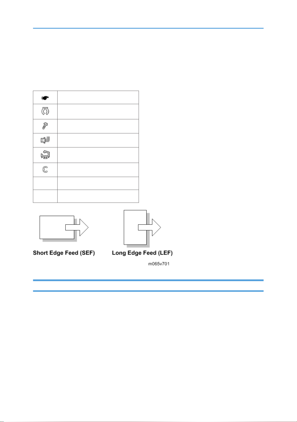
Symbols, Abbreviations and Trademarks
This manual uses several symbols and abbreviations. The meaning of those symbols and abbreviations
are as follows:
See or Refer to
Clip ring
Screw
Connector
Clamp
E-ring
SEF Short Edge Feed
LEF Long Edge Feed
Trademarks
Microsoft®, Windows®, and MS-DOS® are registered trademarks of Microsoft Corporation in the
United States and /or other countries.
PostScript® is a registered trademark of Adobe Systems, Incorporated.
PCL® is a registered trademark of Hewlett-Packard Company.
Ethernet® is a registered trademark of Xerox Corporation.
PowerPC® is a registered trademark of International Business Machines Corporation.
Other product names used herein are for identification purposes only and may be trademarks of their
respective companies. We disclaim any and all rights involved with those marks.
9
Page 12

TABLE OF CONTENTS
Important Safety Notices................................................................................................................................... 1
Responsibilities of the Customer Engineer.................................................................................................... 1
Customer Engineer................................................................................................................................ 1
Reference Material for Maintenance...................................................................................................1
Before Installation, Maintenance..................................................................................................................1
Shipping and Moving the Machine..................................................................................................... 1
Power......................................................................................................................................................1
Installation, Disassembly, and Adjustments.........................................................................................2
Special Tools..........................................................................................................................................2
During Maintenance...................................................................................................................................... 2
General.................................................................................................................................................. 2
Safety Devices........................................................................................................................................3
Organic Cleaners..................................................................................................................................3
Lithium Batteries......................................................................................................................................3
Power Plug and Power Cord................................................................................................................ 4
After Installation, Servicing............................................................................................................................4
Disposal of Used Items..........................................................................................................................4
Points to Confirm with Operators......................................................................................................... 5
Special Safety Instructions for Toner.............................................................................................................5
Accidental Physical Exposure...............................................................................................................5
Handling and Storing Toner................................................................................................................. 6
Toner Disposal....................................................................................................................................... 6
Safety Instructions for this Machine...............................................................................................................6
Prevention of Physical Injury................................................................................................................. 6
Health Safety Conditions...................................................................................................................... 7
Observance of Electrical Safety Standards.........................................................................................7
Safety and Ecological Notes for Disposal...........................................................................................7
Laser Safety.....................................................................................................................................................8
Symbols, Abbreviations and Trademarks.........................................................................................................9
Trademarks..................................................................................................................................................... 9
1. Product Information
Specifications....................................................................................................................................................21
Machine Configuration....................................................................................................................................22
10
Page 13

Machine Configuration............................................................................................................................... 22
Guidance for Those Familiar with Predecessor Products.............................................................................. 23
Different Points from Previous Products...................................................................................................... 23
Overview.......................................................................................................................................................... 24
Mechanical Component Layout................................................................................................................. 24
Paper Path.................................................................................................................................................... 25
Drive Layout..................................................................................................................................................26
2. Installation
Installation Requirements................................................................................................................................. 29
Environment..................................................................................................................................................29
Machine Level..............................................................................................................................................30
Machine Space Requirements....................................................................................................................30
Power Requirements.................................................................................................................................... 31
Optional Unit Combinations............................................................................................................................32
Machine Options.........................................................................................................................................32
Controller Options....................................................................................................................................... 32
Printer Installation............................................................................................................................................. 33
Installation Procedure..................................................................................................................................33
Unpacking........................................................................................................................................... 33
Installing the toner............................................................................................................................... 37
Loading Paper..................................................................................................................................... 38
Turning Power On............................................................................................................................... 40
Selecting the Panel Display Language.............................................................................................. 41
Printing the Test Page.......................................................................................................................... 42
Settings Relevant to the Service Contract..........................................................................................42
Meter Click Charge..................................................................................................................................... 42
Moving the Machine................................................................................................................................... 45
Transporting the Machine........................................................................................................................... 45
Paper Feed Unit (M384).................................................................................................................................46
Caster Table (M393).......................................................................................................................................48
Accessory Check..........................................................................................................................................48
Installation Procedure..................................................................................................................................49
For Installing the Caster Table (M393) Only................................................................................... 49
11
Page 14

For Installing with the Paper Feed Unit (M384)............................................................................... 53
Tray Heater.......................................................................................................................................................57
Component Check.......................................................................................................................................57
Tray Heater (Mainframe)............................................................................................................................ 58
Tray Heater (Optional Unit)........................................................................................................................62
Component Check.............................................................................................................................. 62
For Installing the Tray Heater in M384.............................................................................................63
For Installing the Securing Bracket.....................................................................................................69
Controller Options............................................................................................................................................72
Overview...................................................................................................................................................... 72
I/F Card Slots......................................................................................................................................72
SD Card Slots...................................................................................................................................... 73
Installation Procedure for USB Device Server Option Type M12........................................................... 73
Component Check.............................................................................................................................. 73
Interface Board Surface......................................................................................................................74
Installation Procedure......................................................................................................................... 74
What Do the LED Indications Mean?................................................................................................ 78
IP Address Setting................................................................................................................................79
SD Card Appli Move...................................................................................................................................80
Overview............................................................................................................................................. 80
Outline of SD Card Appli Move........................................................................................................ 80
Move Exec...........................................................................................................................................81
Undo Exec........................................................................................................................................... 82
3. Preventive Maintenance
Maintenance Tables........................................................................................................................................ 83
4. Replacement and Adjustment
Notes on the Main Power Switch................................................................................................................... 85
Push Switch...................................................................................................................................................85
Characteristics of the Push Switch (DC Switch).................................................................................85
Shutdown Method...............................................................................................................................86
Forced Shutdown................................................................................................................................ 86
Before You Start............................................................................................................................................... 87
Special Tools.................................................................................................................................................... 88
12
Page 15

Tools..............................................................................................................................................................88
Exterior Covers................................................................................................................................................. 89
Left Cover......................................................................................................................................................89
Right Cover...................................................................................................................................................90
Rear Cover................................................................................................................................................... 91
When Reinstalling the Rear Cover.....................................................................................................91
Top Cover.....................................................................................................................................................92
When Reinstalling the Top Cover...................................................................................................... 93
Operation Panel...........................................................................................................................................93
Inner Left Upper Cover................................................................................................................................ 94
Inner Left Front Cover.................................................................................................................................. 95
Inner Left Rear Cover................................................................................................................................... 96
Inner Left Lower Cover.................................................................................................................................96
Inner Right Front Cover................................................................................................................................97
Inner Right Rear Cover................................................................................................................................ 99
Laser Optics....................................................................................................................................................100
Caution Decal Locations...........................................................................................................................100
Laser Unit....................................................................................................................................................100
Before removing the old laser unit...................................................................................................100
Recovery procedure for no replacement preparation of laser unit.............................................. 101
Removing the laser unit.................................................................................................................... 101
After installing a new laser unit........................................................................................................102
Laser Unit Fan............................................................................................................................................ 104
When installing the laser unit fan.................................................................................................... 104
LDU Shutter Motor.....................................................................................................................................105
Image Creation..............................................................................................................................................106
PCDU (Photo Conductor and Development Unit)...................................................................................106
When installing a new PCDU.......................................................................................................... 107
Waste Toner Bottle....................................................................................................................................110
Toner Supply Tube.................................................................................................................................... 111
Toner Supply Motor.................................................................................................................................. 117
Toner Collection Motor.............................................................................................................................118
Waste Toner Bottle Full Sensor.................................................................................................................120
13
Page 16

Waste Toner Bottle Set Sensor.................................................................................................................120
RFID CPU Board........................................................................................................................................121
RFID Board.................................................................................................................................................122
Development Fan...................................................................................................................................... 123
When installing the development fan..............................................................................................124
Image Transfer............................................................................................................................................... 125
ITB (Image Transfer Belt) Unit...................................................................................................................125
Image Transfer Belt....................................................................................................................................127
When Installing the Image Transfer Belt......................................................................................... 132
ITB Contact Motor.....................................................................................................................................133
ITB Contact Sensor....................................................................................................................................134
ID Sensor Board........................................................................................................................................ 136
After installing a new ID sensor board............................................................................................138
Paper Transfer................................................................................................................................................140
PTR (Paper Transfer Roller) Unit............................................................................................................... 140
When Installing the PTR Unit............................................................................................................140
PTR Contact Motor.................................................................................................................................... 141
PTR Contact Sensor................................................................................................................................... 142
Temperature/Humidity Sensor.................................................................................................................143
Drive Unit........................................................................................................................................................145
Gear Unit................................................................................................................................................... 145
When installing the gear unit........................................................................................................... 151
Toner Supply Fan...................................................................................................................................... 151
When installing the toner supply fan...............................................................................................152
Toner Supply Fan Base.................................................................................................................... 152
Drum Motor: CMY.................................................................................................................................... 152
Development Motor: CMY....................................................................................................................... 153
ITB Unit/ Drum-K/ Development-K Motor............................................................................................. 154
Development Clutch: K............................................................................................................................. 154
Fusing/Paper Exit Motor.......................................................................................................................... 155
Front Door Sensor..................................................................................................................................... 155
Motors with Bracket.................................................................................................................................. 156
Registration Motor.....................................................................................................................................158
14
Page 17

Paper Feed Motor..................................................................................................................................... 159
Vertical Transport Motor...........................................................................................................................160
Drum Phase Sensor: CMY........................................................................................................................ 161
Drum Phase Sensor: K...............................................................................................................................161
Drive Unit Fan............................................................................................................................................ 162
When installing the drive unit fan.................................................................................................... 163
Fusing..............................................................................................................................................................164
Fusing Unit..................................................................................................................................................164
When installing the fusing unit......................................................................................................... 164
Cleaning Unit.............................................................................................................................................164
Pressure Roller Fusing Lamp......................................................................................................................165
Pressure Roller............................................................................................................................................168
When Reinstalling the Pressure Roller.............................................................................................170
Heating Roller Fusing Lamp......................................................................................................................170
Fusing Belt.................................................................................................................................................. 175
Fusing, Heating and Tension Roller......................................................................................................... 177
When Reinstalling the Fusing Roller................................................................................................ 177
Heating Roller Thermostat.........................................................................................................................178
Heating Roller Thermistor..........................................................................................................................179
Pressure Roller Thermistor......................................................................................................................... 180
Pressure Roller Thermostat........................................................................................................................ 181
Thermopile................................................................................................................................................. 181
Paper Feed..................................................................................................................................................... 183
Separation Roller.......................................................................................................................................183
Pick-up and Paper Feed Rollers............................................................................................................... 183
Paper Feed Unit.........................................................................................................................................184
Registration Sensor....................................................................................................................................186
Vertical Transport Sensor..........................................................................................................................187
Paper Height Sensor 1..............................................................................................................................188
Paper Height Sensor 2..............................................................................................................................189
Paper Lift Sensor........................................................................................................................................ 190
Paper End Sensor...................................................................................................................................... 191
Paper Feed Sensor.................................................................................................................................... 192
15
Page 18

Tray Lift Motor............................................................................................................................................194
Tray 1 Set Sensor...................................................................................................................................... 195
Paper Size Sensor Board..........................................................................................................................197
Cleaning the Paper Dust Container......................................................................................................... 197
Paper Exit........................................................................................................................................................198
Paper Exit Unit........................................................................................................................................... 198
Paper Exit Sensor.......................................................................................................................................200
Inverter Sensor...........................................................................................................................................203
Paper Overflow Sensor.............................................................................................................................204
Fusing Exit Sensor......................................................................................................................................205
Inverter Motor............................................................................................................................................206
Fusing Cooling Fan....................................................................................................................................206
When installing the fusing cooling fan............................................................................................207
Upper Cover Sensor................................................................................................................................. 207
Duplex Unit.....................................................................................................................................................208
Duplex Unit................................................................................................................................................ 208
By-pass Tray Unit.......................................................................................................................................210
Duplex Entrance Sensor............................................................................................................................212
Duplex Exit Sensor.................................................................................................................................... 214
Fusing Entrance Sensor.............................................................................................................................215
Duplex/By-pass Motor.............................................................................................................................216
By-pass Paper End Sensor........................................................................................................................220
By-pass Feed Roller, Friction Pad.............................................................................................................221
HVPS: D......................................................................................................................................................224
Fusing Fan.................................................................................................................................................. 225
When installing the fusing fan..........................................................................................................226
Electrical Components...................................................................................................................................227
Boards........................................................................................................................................................ 227
HDD (Option)............................................................................................................................................ 229
Disposal of HDD Units......................................................................................................................230
Reinstallation..................................................................................................................................... 231
Controller Board........................................................................................................................................231
When installing the new controller board...................................................................................... 232
16
Page 19

Bridge Board............................................................................................................................................. 233
PSU............................................................................................................................................................. 234
Controller Box............................................................................................................................................235
BCU............................................................................................................................................................ 238
When installing the new BCU..........................................................................................................239
Removing the BCU with bracket......................................................................................................240
HVPS: T1T2 Board.................................................................................................................................... 241
HVPS: CB Board........................................................................................................................................242
DC Switch Board.......................................................................................................................................244
NVRAM Replacement Procedure............................................................................................................ 245
NVRAM on the BCU........................................................................................................................ 245
NVRAM on the Controller................................................................................................................246
Adjustments.................................................................................................................................................... 248
Gamma Adjustment...................................................................................................................................248
Summary............................................................................................................................................248
Adjustment Procedure.......................................................................................................................250
5. System Maintenance Reference
Service Program Mode.................................................................................................................................253
Service Mode Operation......................................................................................................................... 253
Accessing the Required Program.................................................................................................... 253
Inputting a Value or Setting for a Service Program....................................................................... 253
Exiting Service Mode....................................................................................................................... 253
Remarks......................................................................................................................................................254
Display on the Control Panel Screen.............................................................................................. 254
Bit Switch Programming............................................................................................................................ 256
Service SP Mode Tables............................................................................................................................... 258
SP1-XXX (Service Mode)..........................................................................................................................258
Engine SP Mode Tables: SP1000................................................................................................................271
SP1-XXX (Feed)......................................................................................................................................... 271
Engine SP Mode Tables - SP2000...............................................................................................................297
SP2-XXX (Drum).........................................................................................................................................297
Engine SP Mode Tables - SP3000...............................................................................................................397
SP3-XXX (Process)..................................................................................................................................... 397
17
Page 20

Engine SP Mode Tables - SP4000...............................................................................................................419
Engine SP Mode Tables - SP5000...............................................................................................................420
SP5-XXX (Mode)....................................................................................................................................... 420
Engine SP Mode Tables - SP6000...............................................................................................................472
Engine SP Mode Tables - SP7000...............................................................................................................473
SP7-XXX (Data Log).................................................................................................................................. 473
Engine SP Mode Tables - SP8000...............................................................................................................504
SP8-xxx: Data Log2.................................................................................................................................. 504
Input Check/ Output Check......................................................................................................................... 531
Input Check Table..................................................................................................................................... 531
Printer.................................................................................................................................................531
Table 1: Paper Size Switch (Tray 1)............................................................................................... 534
Table 2: Paper Height Sensor..........................................................................................................535
Output Check Table.................................................................................................................................. 535
Printer.................................................................................................................................................535
Test Pattern Printing........................................................................................................................................542
Test Pattern Printing....................................................................................................................................542
Firmware Update...........................................................................................................................................544
Type of Firmware.......................................................................................................................................544
SD Card Firmware Updating....................................................................................................................544
Before You Begin..............................................................................................................................544
File Arrangement.............................................................................................................................. 545
Update Procedure............................................................................................................................ 546
Error Handling.................................................................................................................................. 547
Power Failure.................................................................................................................................... 548
Handling Firmware Update Errors...........................................................................................................548
Error Message Table........................................................................................................................548
NVRAM Data Upload/Download.............................................................................................................. 550
Uploading NVRAM Data......................................................................................................................... 550
Downloading NVRAM Data.................................................................................................................... 551
Address Book Upload/Download.............................................................................................................. 552
Information List...........................................................................................................................................552
Download.................................................................................................................................................. 552
18
Page 21

Upload....................................................................................................................................................... 553
Capturing the Debug Logs............................................................................................................................ 554
Overview....................................................................................................................................................554
Types of debug logs that can be saved..........................................................................................554
Operation Log Security.................................................................................................................... 555
Storing the Debug Logs with SD Card.....................................................................................................556
Retrieving Debug Logs.............................................................................................................................. 556
Procedure for Retrieving the Debug Log.........................................................................................556
SP Text Mode (Saving SMC List to SD Card)..............................................................................................558
Overview....................................................................................................................................................558
SP Text Mode....................................................................................................................................558
Procedure...................................................................................................................................................558
File Names of the Saved SMC Lists......................................................................................................... 559
Error Messages..........................................................................................................................................560
DIP Switches...................................................................................................................................................561
Controller Board........................................................................................................................................561
6. Troubleshooting
SC Tables....................................................................................................................................................... 563
Service Call Conditions.............................................................................................................................563
Summary............................................................................................................................................563
SC1xx: Scanning.......................................................................................................................................564
SC 2xx: Exposure......................................................................................................................................564
SC3xx: Image Processing – 1..................................................................................................................571
SC4xx: Image Processing - 2...................................................................................................................576
SC5xx: Paper Feed and Fusing................................................................................................................581
SC6xx: Device Communication............................................................................................................... 595
SC8xx: Overall System.............................................................................................................................599
SC9xx: Miscellaneous.............................................................................................................................. 609
Process Control Results..................................................................................................................................612
Developer Initialization Result.................................................................................................................. 612
Process Control Self-Check Result............................................................................................................613
Vsg Adjustment Result.......................................................................................................................615
Line Position Adjustment Result................................................................................................................. 615
19
Page 22

Troubleshooting Guide..................................................................................................................................617
Blank Print...................................................................................................................................................617
All-black Print.............................................................................................................................................617
Missing CMY Color...................................................................................................................................618
Light Print.................................................................................................................................................... 618
Repeated Spots or Lines on Prints............................................................................................................ 618
Dark Vertical Line on Prints....................................................................................................................... 620
White Horizontal Lines or Bands..............................................................................................................620
Missing Parts of Images............................................................................................................................ 621
Dirty Background.......................................................................................................................................621
Partial CMY Color Dots............................................................................................................................ 621
Dark Irregular Streaks on Prints................................................................................................................621
CMY Color Irregular Streaks....................................................................................................................622
Ghosting.....................................................................................................................................................622
Unfused or Partially Fused Prints.............................................................................................................. 622
Image Skew............................................................................................................................................... 623
Background Stain......................................................................................................................................623
No Printing on Paper Edge.......................................................................................................................624
Image not centered when it should be.................................................................................................... 624
Jam Detection.................................................................................................................................................625
Paper Jam Display.....................................................................................................................................625
Jam Codes and Display Codes................................................................................................................625
Paper Size Code...............................................................................................................................627
Electrical Component Defects.......................................................................................................................628
Sensors....................................................................................................................................................... 628
Optional Paper Feed Unit................................................................................................................632
Blown Fuse Conditions..............................................................................................................................633
Power Supply Unit............................................................................................................................ 633
LEDs............................................................................................................................................................ 634
INDEX...........................................................................................................................................................635
20
Page 23

1. Product Information
Specifications
See "Appendices" for the following information:
• "General Specifications"
• "Supported Paper Sizes"
• "Software Accessories"
• "Optional Equipment"
21
Page 24

1. Product Information
Machine Configuration
Machine Configuration
Item Machine Code Remarks
SP C440DN M257
Paper Feed Unit PB1020 M384
Caster Table Type C M393 Common with Z-P1 (M065/ M066)
Hard Disk Drive Option Type P7 M479-00
IEEE802.11 Interface unit Type
O
IEEE1284 Interface Board Type
A
USB Device Server Option Type
M12
Camera Direct Print Card Type
P7
VM CARD Type P7 M479-08
IPDS Unit Type P7 M479-01, -02, -03
Direct Print Option Type P7 M479-05, -06, -07
M417
B679-17
D3A7
M479-04
Up to three tray units can be installed.
Common with Z-P1 (M065/ M066)
Common with Z-P1 (M065/ M066)
22
SD CARD SET FOR FONT TYPE
D FOR MFP
D641-54
Page 25

Guidance for Those Familiar with Predecessor Products
Guidance for Those Familiar with Predecessor
Products
The Z-P2b (M257) is similar to the Z-P1a (M065) and P1b (M066) models.
If you have experience with those products, the following information will be of help when you read this
manual.
Different Points from Previous Products
New Predecessor Models
M257 M065 M066
PPM
Controller Type GW+ GW
Power Switch DC Switch AC Switch
Light Detection Sensor Available Not available
HDD Option Option Standard
Additional network
interface port
ELP-NX Option Option Standard
Data Overwrite
Security Unit and HDD
Encryption Unit
Log-storing function Available Not available
LT: 42 ppm,
A4: 40 ppm
Option Not available
On board SD card SD card
LT: 37 ppm,
A4: 35 ppm
LT: 42 ppm,
A4: 40 ppm
23
Page 26
1. Product Information
Overview
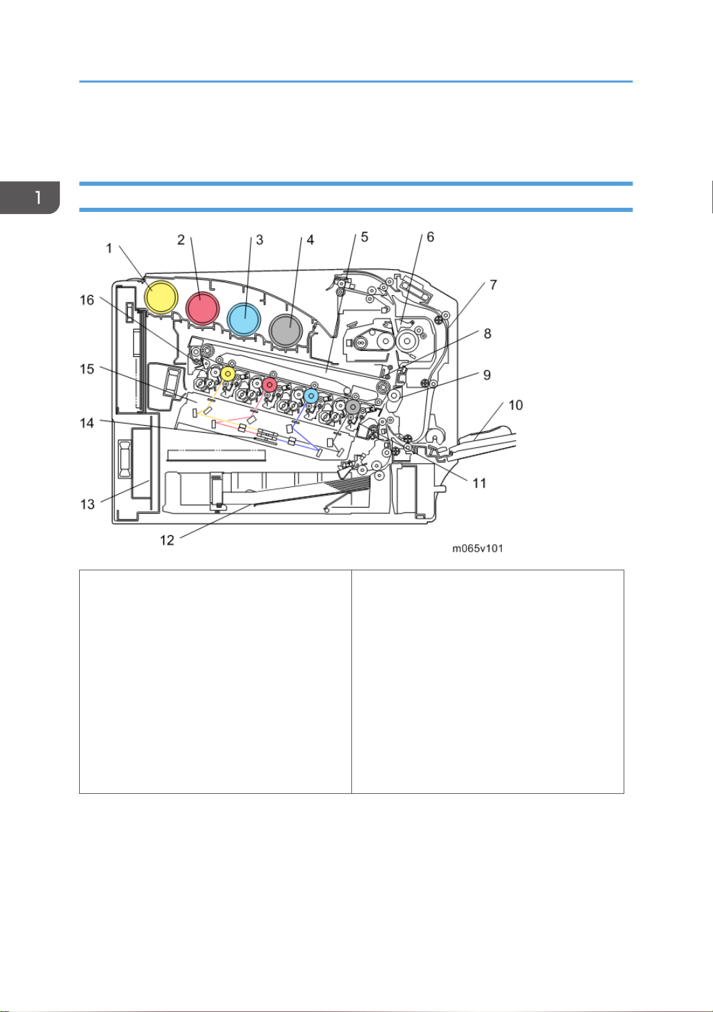
Mechanical Component Layout
24
1. Toner Bottle [Y]
2. Toner Bottle [M]
3. Toner Bottle [C]
4. Toner Bottle [K]
5. ITB (Image Transfer Belt) Unit
6. Fusing Unit
7. Duplex Unit
8. ID Sensor
9. PTR (Paper Transfer Roller)
10. By-pass Tray
11. PCDU (Photo Conductor Development Unit)
12. Standard Paper Feed Tray (Tray 1)
13. PSU (Power Supply Unit)
14. Polygon Mirror Motor
15. LDU
16. ITB (Image Transfer Belt) Cleaning Unit
Page 27
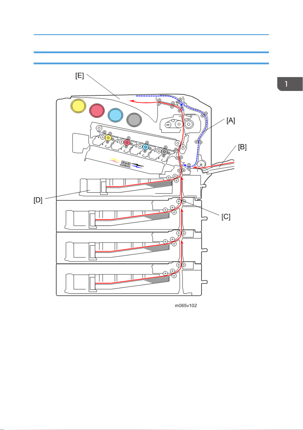
Paper Path
Overview
[A]: Duplex Unit
[B]: By-pass Tray
[C]: Optional Paper Feed Trays (Trays 2, 3, and 4)
[D]: Standard Paper Feed Tray (Tray 1)
[E]: Standard Paper Exit Tray
25
Page 28
1. Product Information
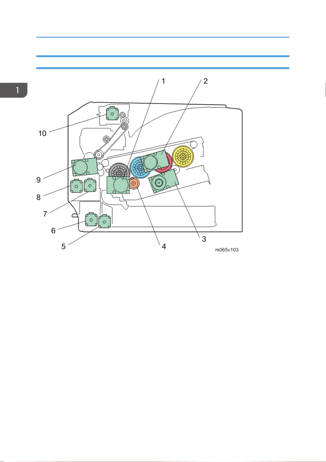
Drive Layout
26
1. ITB Unit/ Drum-K/ Development-K Motor:
This controls the OPC for black, development unit for black, and ITB unit.
2. Drum Motor: CMY:
This controls the OPCs for cyan, magenta, and yellow.
3. Development Motor: CMY:
This controls the color development units (cyan/ magenta/ yellow).
4. Development Clutch: K:
This controls the drive power to the development unit for black.
5. Paper Feed Motor:
This controls the paper feed mechanisms (tray 1).
6. Vertical Transport Motor:
This controls the vertical transport roller.
7. Registration Motor:
This controls the registration rollers.
8. Duplex/By-pass Motor:
Page 29

This controls the duplex entrance, relay, exit, and by-pass feed rollers.
9. Fusing/ Paper Exit Motor:
This controls the fusing unit and paper exit rollers.
10. Inverter Motor:
This controls the inverter roller.
Overview
27
Page 30

1. Product Information
28
Page 31

2. Installation
Installation Requirements
Environment
1. Temperature Range: 10°C to 32°C (50°F to 89.6°F)
2. Humidity Range: 15% to 80% RH
3. Ambient Illumination: Less than 1500 lux (do not expose to direct sunlight)
4. Ventilation: 3 times/hr/person or more
5. Do not let the machine get exposed to the following:
1) Cool air from an air conditioner
2) Heat from a heater
6. Do not install the machine in areas that are exposed to corrosive gas.
7. Install the machine at locations lower than 2,000 m (6,500 ft.) above sea level.
8. Install the machine on a strong, level base. (Inclination on any side must be no more than 5 mm.)
9. Do not install the machine in areas that get strong vibrations.
29
Page 32

2. Installation
Machine Level
Front to back: Within 5 mm (0.2")
Right to left: Within 5 mm (0.2")
Machine Space Requirements
• This machine, which uses high voltage power sources, can generate ozone gas. High ozone
density is harmful to human health. Therefore, the machine must be installed in a well-ventilated
room.
A: Over 500 mm (19.7")
B: Over 20 mm (0.8")
C: Over 100 mm (4.0")
D: Over 700 mm (27.6")
Above the machine: Over 350 mm (13.8")
Put the machine near the power source with the clearance.
30
Page 33

Power Requirements
• Insert the plug firmly in the outlet.
• Do not use an outlet extension plug or cord.
• Ground the machine.
1. Input voltage level:
120 V to 127 V, 60 Hz: More than 12 A
220 V to 240 V, 50 Hz/60 Hz: More than 8 A
2. Permissible voltage fluctuation: NA: ±8.66 %/ EU: ±10 %
3. Do not put things on the power cord.
Installation Requirements
31
Page 34

2. Installation
Optional Unit Combinations
Machine Options
U: User installation, C: CE installation
No. Options Remarks
1 Paper Feed Unit PB1020 (M384) U/C Up to x 3
User: For installing on the
table
CE: For installing on the
floor
2 Caster Table Type C (M393) C Install the caster table if
the machine is on the
floor.
Controller Options
U: User installation, C: CE installation
No. Options Remarks
1 Hard Disk Drive Option Type P7 (M479) U -
2 IEEE1284 Interface Board Type A (B679-17) U
4 USB Device Server Option Type M12 C
5 Camera Direct Print Card Type P7 U
6 VM CARD Type P7 U
7 IPDS Unit Type P7 U
8 XPS Direct Print Option Type P7 U
9 SD CARD SET FOR FONT TYPE D FOR MFP(D641-54) U
I/F slot3 IEEE802.11 Interface unit Type O (M417) U
SD slot 1
32
Page 35

Printer Installation
Printer Installation
Installation Procedure
• Keep the shipping retainers after you install the machine. You may need them in the future if you
transport the machine to another location.
Unpacking
• When lifting the machine, use the inside grips on both sides of the machine.
• If not, the machine could be dropped. This may cause an injury and may damage the machine.
• Place no objects on the left cover or on the inner cover.
1. Remove the plastic bag.
2. Lift the machine with four people by using the inset grips on both sides of the machine.
• Do not hold the machine at the front and rear bottom corners when lifting.
• Grips must be used only for moving the machine without caster table and paper feed unit. If
these items are also installed when you move the machine, do not use the grips.
• Do not remove the tapes before placing the machine.
• Lower the machine slowly and carefully, so as not to pinch your hands.
3. Remove the tape from the printer.
33
Page 36

2. Installation
4. Open the left cover [A].
5. Turn the green lever counterclockwise ( ), and then slowly open the inner cover ( ).
34
6. Remove the securing pin, as shown, from the transfer unit. Pinch it ( ), and then pull it
out ( - ).
Page 37

Printer Installation
7. Turn the green lever of the transfer unit counterclockwise to unlock the unit ( ). Remove
the protective sheet, as shown. Pinch the orange tape ( ), and then pull it out ( ).
8. Turn the green lever clockwise to lock the unit.
9. Close the inner cover.
35
Page 38

2. Installation
10. Lock the inner cover by pushing on both ends ( ), and then turning the green lever
clockwise ( ).
11. Close the left cover.
• Using both hands, push the left cover firmly, until it clicks into place.
36
Page 39

12. Put labels "1" on the front of the paper tray.
Installing the toner
1. Open the upper cover.
2. Shake the toner bottles up and down seven or eight times.
Printer Installation
37
Page 40

2. Installation
3. Install the yellow toner bottle first. Holding the toner bottle horizontally with the label
facing up, align the label with the position of the triangular mark.
• Be sure to set the toner bottles so that they are straight and flat.
• Carefully align the label on each toner bottle with the triangular mark on the receiving side.
Loading Paper
38
4. Push in the toner bottle until you hear a clicking sound.
• Do not repeatedly insert and remove toner bottles. This causes toner leakage.
5. Close the upper cover.
1. Pull out the paper tray until it stops.
Page 41

Printer Installation
2. Lift it slightly, and then pull it out.
3. Pinch the green clips on the side guide and the end guide, and then adjust the guides to
the paper size being loaded.
4. Load the new paper stack print side up, making sure the paper is flush against the paper
guides.
39
Page 42

2. Installation
5. Adjust the paper guides to close any gaps.
• Do not move paper loaded in the tray more than a few millimeters. Excessive movement of
loaded paper can cause edges of sheets to snag on the openings of the tray's lifting plate,
resulting in sheets being folded or becoming jammed.
• When adjusting the paper width, use the right side guide only, with the green clip. Do not
hold the left side guide at this time, or skew will occur.
6. Lift the front of the paper tray, and slowly slide the paper tray back until it stops. Make
sure that the paper tray is fully inserted to prevent paper jams.
Turning Power On
• Turn off the power switch whenever you plug in and unplug the power cord.
40
Page 43

1. Plug in the machine.
2. Turn on the power switch.
Printer Installation
• Do not turn off the power switch until initialization is completed ("Ready" appears on the
display when initialization is completed). Otherwise, the machine may malfunction.
Selecting the Panel Display Language
• You can select one of these languages (the default is English): English, German, French, Italian,
Dutch, Swedish, Norwegian, Danish, Spanish, Finnish, Portuguese, Czech, Polish or Hungarian.
• You do not have to do this procedure if you use English. Do this procedure if you want to use a
different language.
41
Page 44

2. Installation
1. Turn on the power switch of the printer.
• "Ready" shows on the panel display after the machine warms up.
2. Press the "Menu" key.
3. Press the " " or " " key to select "Language."
4. Press the "OK" key.
5. Press the " " or " " key to select the language you want.
6. Press the "OK" key.
7. Press the "Menu" key to return to the initial screen.
Printing the Test Page
You can check if the printer works correctly by printing a test page such as the configuration page.
However, you cannot check the connection between the printer and the computer by printing the test
page.
1. Turn on the power switch of the printer.
• "Ready" shows on the panel display after the machine warms up.
2. Press the "Menu" key.
3. Press the " " or " " key to select "List/Test Print".
4. Press the "OK" key.
5. Press the " " or " " key to select "Config. Page".
6. Press the "OK" key.
7. The test printing starts shortly after.
8. Press the "Menu" key to return to the initial screen.
9. Turn off the power switch of the printer.
Settings Relevant to the Service Contract
Change the necessary settings depending on the each customer's service contract. For details, refer to
"Meter Click Charge" following this section.
Meter Click Charge
Basically, there are two ways to set up this function.
42
Page 45

Printer Installation
Meter click charge enabled (SP 5-930-001 set to "1 (enabled)"): The counter can be displayed and
printed by the customer. The technician can then call the customer and ask them to read the counter.
Meter click charge disabled (SP 5-930-001 set to "0 (disabled)"; this is the default setting): The counter
cannot be displayed or printed by the customer. To check the counter, the technician must print the SMC
report (SP 5-990).
• You must select one of the counter methods (developments/prints) in accordance with the contract
(See “SP5-045-001”.).
• If the setting of SP5-930-001 is set to "1 (enabled)", the settings of SP5-930-010, -014 and -016
must be adjusted.
43
Page 46

2. Installation
Item SP No. Function Default
Meter Click
Charge
Meter Click
Charge:
PCDU
Meter Click
Charge:
Image
Transfer Belt
Unit
SP5-930-001 Enables or disables Meter Click Charge.
When enabled:
• The counter menu shows
immediately after you push the
"Menu" key. The "Counter Method"
(SP5-045) sets the type of the
counter.
• You can print the counter from the
counter menu.
When disabled:
• The counter menu does not show.
SP5-930-010 Enables or disables the PM alert for the
PCDUs.
If this SP is enabled, an alert message is
displayed when the PCDUs need to be
replaced.
SP5-930-014 Enables or disables the PM alert for the
image transfer belt unit.
If this SP is enabled, an alert message is
displayed when the image transfer belt
unit needs to be replaced.
"0": OFF
"1": No alert
"1": No alert
44
Meter Click
Charge:
Fusing Unit
Counter
method
SP5-930-016 Enables or disables the PM alert for the
fusing unit.
If this SP is enabled, an alert message is
displayed when the fusing unit needs to
be replaced.
SP5-045-001 Specifies if the counting method used in
meter charge mode is based on
developments or prints.
"1": No alert
"1": Prints
Page 47

Printer Installation
Item SP No. Function Default
Service Tel:
Telephone /
Facsimile
SP5-812-001 and
-002
-001: shows or sets the telephone
number of the service representative.
-002: shows or sets the fax number of
the service station. The number is printed
on the counter list when the "Meter Click
Charge" is enabled. User can send a fax
message with the counter list.
-
Moving the Machine
This section shows you how to manually move the machine from one floor to another floor. See the
section "Transporting the Machine" if you have to pack the machine and move it a longer distance.
• Remove all trays from the optional paper feed unit.
Transporting the Machine
1. Make sure there is no paper left in the paper trays. Then fix down the bottom plates with
a sheet of paper and tape.
2. Do one of the following:
• Attach shipping tape to the covers and doors.
• Shrink-wrap the machine tightly.
• After you move the machine, make sure you do the "Auto Color Registration" as follows. This
optimizes color registration.
• 1) Do the "Forced Line Position Adj. Mode c" (SP2-111-3).
• 2) Then do the "Forced Line Position Adj. Mode a" (SP2-111-1).
• To check if SP 2-111-1 was successful, watch the screen during the process. A message is
displayed at the end. Also, you can check the result with SP 2-194-10 to -12.
45
Page 48

2. Installation
Paper Feed Unit (M384)
For details, refer to the "Hardware Guide" for this machine.
• Install the caster table and securing bracket if the machine is installed on the floor (page 48
"Caster Table (M393)").
1. Remove the tape from the paper feed unit.
2. Lift the machine with four people by using the inset grips on both sides of the machine.
46
Page 49

Paper Feed Unit (M384)
3. Align the machine with the two upright pins on the paper feed unit and then lower the
machine slowly.
• When installing two or three units, first connect the units to each other (using the same
procedure as described above), and then connect them as a single unit to the machine.
47
Page 50

2. Installation
Caster Table (M393)
Accessory Check
Check the quantity and condition of the accessories against the following list.
No. Description Q'ty
1 Screws (M3 x 8) 3
2 Spring washer screws 13
3 Washers 3
4 Spring washers 3
5 Securing pins 2
6 Securing brackets (left) 3
7 Securing holders 3
8 Securing brackets (right rear) 3
9 Table joint bracket (left) 1
10 Table joint brackets (right front) 1
11 Table joint bracket (right rear) 1
• Some of these accessories may not be used. It differs depending on how many optional trays are
installed in the machine.
48
Page 51

Installation Procedure
Caster Table (M393)
• Handles must be used only for moving the machine without caster table and paper feed unit. If
either or both of these items are installed when you move the machine, do not use the handles.
For Installing the Caster Table (M393) Only
1. Open the left cover.
2. Inner left lower cover ( x 3)
49
Page 52

2. Installation
3. Push the holder [A] down.
4. Remove the holder [A].
50
5. Reinstall the inner left lower cover ( x 3).
6. Close the left cover.
Page 53

7. Install the two pins [A] in the screw holes.
8. Lift the machine and install it on the caster table.
• Hold the handle and grips of the machine when you lift and move the machine.
9. Open the duplex unit.
10. Right cover [A] ( x 1)
Caster Table (M393)
51
Page 54

2. Installation
11. Install the two table joint brackets [A] at the right side ( x 5).
12. Reinstall the right cover ( x 1).
13. Install the table joint bracket [A] at the left side ( x 2).
14. Close the front door.
52
Page 55

15. Adjust the plate [A] until it is level by rotating each screw.
For Installing with the Paper Feed Unit (M384)
1. Remove all tapes from the paper feed unit.
Caster Table (M393)
2. Lift the paper feed unit, and then install it on the caster table.
3. Lift the machine and install it on the paper feed unit.
• Hold the handle and grips of the machine when you lift and move the machine.
4. Open the front door.
5. Right cover (page 49)
6. Remove the right cover [A] of the paper feed unit ( x 2).
53
Page 56

2. Installation
7. Install the securing bracket [A] ( x 2).
• If two or three optional paper feed units are to be installed, install the securing bracket [A] at
the right side of the optional paper feed units in a similar location to that shown below to
secure them ( x 2).
8. Install the joint table brackets [B] ( x 5).
9. Install the securing holder [C].
54
10.
Reinstall the right cover and the right cover of the paper feed unit ( x 2).
Page 57

11. Remove the left cover [A] of the paper feed unit ( x 2).
12. Remove the screw shown above.
Caster Table (M393)
13. Install the table joint bracket [A] ( x 2).
14. Install the securing bracket [B] ( x 1 (M3x8) [C], spring washer x 1 [D], washer x 1 [E]).
• If two or three optional paper feed units are to be installed, install the securing bracket [B] at
the left side of the optional paper feed units in a similar location to that shown above to secure
them ( x 1 (M3x8) [C], spring washer x 1 [D], washer x 1 [E]).
55
Page 58

2. Installation
15. Reinstall the right cover of the paper feed unit ( x 2).
16. Close the front door.
17. Adjust the plate until it is level by rotating each screw (page 49).
56
Page 59

Tray Heater
Component Check
Check the quantity and condition of the accessories against the following list.
No. Description Q'ty
1 Heater cover 1
2 Tray heater 1
3 Heater bracket 1
4 On-standby decal 1
5 Harness bracket 1
6 Harness 1
Tray Heater
7 Clamp 2
8 Screw (M3 x 6) 7
57
Page 60

2. Installation
Tray Heater (Mainframe)
• Before installing, make sure that the power source rating of the tray heater is same as the machine.
1. Assemble the tray heater ( x 3).
58
• Before installing the tray heater, check if the destination is correct.
• [A]; 120V 9W: NA, 230V 9W: EU/AA
2. Rear cover (page 91)
3. Right cover (page 90)
4. Controller box (page 235)
5. Inner left lower cover (page 96)
6. HVPS: CB bracket (page 242 "HVPS: CB Board")
Page 61

7. Install the heater [A] on the bracket ( x 2).
8. Remove the two clamps [A].
Tray Heater
9. Attach the two clamps [A] (removed in step 8) to the bracket [B].
59
Page 62

2. Installation
10. Route the harnesses as shown below ( x 2).
11. Install the bracket [A] ( x 2).
12. Reinstall the HVPS: CB bracket.
60
Page 63

Tray Heater
13. Pass the heater harness [A] through the hole [B] in the controller box (shown in the red
circle).
14. Reinstall the controller box.
15. Attach the two clamps [A] to the controller box.
16. Connect the relay harness [A] to CN906 [B] ( x 2).
61
Page 64

2. Installation
17. Connect the relay harness [A] to the heater harness [C] ( x 2).
18. Reassemble the machine.
Tray Heater (Optional Unit)
1. Unplug the machine power cord before starting the following procedure.
2. Do the following procedure not to damage any harnesses.
3. Check that no harnesses are damaged or pinched after installation.
Component Check
Check the quantity and condition of the accessories against the following list.
No. Description Q'ty
1 Tray heater 1
2 Securing bracket (right rear) 1
3 Securing holder 1
4 Securing bracket (left) 1
5 On-standby decal 1
6 Edge clamp 1
7 Clamp 6
62
Page 65

No. Description Q'ty
8 Screw (M4 x 8) 3
9 Screw (M3 x 8) 2
10 Spring washer ( 4) 3
11 Spring washer ( 3) 2
12 Washer ( 4) 3
13 Washer ( 3) 2
14 Harness 1
Tray Heater
For Installing the Tray Heater in M384
1. Pull out the tray [A] from the optional paper tray.
63
Page 66

2. Installation
2. Put the tray heater [B] into the optional paper feed unit.
3. Pass the heater harness [A] through the square hole [B].
64
Page 67

Tray Heater
4. Position the tray heater [A] (3 hooks)
5. Install the tray heater [A] in the machine ( x 1 (M4x8) [B], spring washer x 1 ( 4) [C],
washer x 1 ( 4) [D]).
65
Page 68

2. Installation
6. Install the edge clamp [A] and the six clamps.
7. Connect the relay harness [A] to the heater harness [B] ( x 4).
66
8. Route the relay harness [A] as shown above ( x 3).
• Make sure that the connector [B] is placed securely as shown above.
Page 69

Tray Heater
9. If you do not install another optional paper feed unit, replace the screw [A] with the
screw [B] ( x 1 (M3x8) [C], spring washer x 1 ( 3) [D], washer x 1 ( 3) [E]).
Do steps 10 and 11 if you install another optional paper feed unit below M384. If not, go to step
12.
67
Page 70

2. Installation
10. Bracket [A] ( x 1)
11. Install the relay harness [A] as shown above.
• Repeat steps from 1 to 11 if two or three optional paper feed units are to be installed.
12. Rear cover [A] ( x 1)
68
Page 71

13. Bracket [A] ( x 1)
14. Connect the relay harness to the relay harness of the mainframe.
Tray Heater
15. Reassemble the machine.
For Installing the Securing Bracket
• The securing bracket must be installed when the tray heater is installed in the machine with the
paper feed unit (M384).
1. Remove the holder (page 48 "Caster Table (M393)").
2. Reinstall the inner left lower cover ( x 3).
3. Close the left cover.
4. Remove the left cover of the paper feed unit (page 48 "Caster Table (M393)").
69
Page 72

2. Installation
5. Remove the screw.
6. Install the securing bracket [A] ( x 1 (M3x8) [B], spring washer x 1 ( 3) [C], washer x 1
( 3) [D]).
70
7. Remove the right cover of the paper feed unit (page 48 "Caster Table (M393)").
8. Install the securing bracket [A] ( x 2 (M4x8) [B], spring washer x 2 ( 4) [C], washer x 2
( 4) [D]).
Page 73

9. Install the securing holder [E].
Tray Heater
10. Reassemble the machine.
71
Page 74

2. Installation
Controller Options
The following options are available for this machine; refer to the "Hardware Guide" about the
installation procedure for each option except “USB Device Server Option Type M12”. Only “USB
Device Server Option Type M12” should be installed by a customer engineer.
• Hard Disk Drive
• IEEE1284 Interface Board Type A
• IEEE802.11 Interface unit Type O
• USB Device Server Option Type M12
• Camera Direct Print Card Type P7
• IPDS Unit Type P7
• XPS Direct Print Option Type P7
• SD CARD SET FOR FONT TYPE D FOR MFP
• VM CARD Type P7
Overview
This machine has I/F card slot for optional I/F connections and SD card slots applications.
After you install an option, check that the machine can recognize it.
I/F Card Slots
72
• Slot [A] is used for one of the optional I/F connections (only one can be installed): IEEE1284,
IEEE802.11a/b/g/n, USB Device Server Option Type M12
Page 75

Controller Options
SD Card Slots
• Slot 1 [1] is used for “Camera Direct Print Card Type P7”, “IPDS Unit Type P7”, “XPS Direct Print
Option Type P7”, “SD CARD SET FOR FONT TYPE D FOR MFP” or “VM CARD Type P7”.
• Slot 2 [2] is used for installing one of the optional applications for service only (for example,
updating the firmware).
Installation Procedure for USB Device Server Option Type M12
Component Check
No Items Q’ty Remark
1 Interface Board 1
2 USB Cable 1
3 Ferrite Core 4
- Band 2 NA only
• An Ethernet cable is not packed with this option.
73
Page 76

2. Installation
Interface Board Surface
No. Item Description
1 Switch Used to reset to the factory settings.
2 Ethernet port Used to connect the Ethernet cable.
3 USB port
Used to connect this option to the main machine.
Do not use this port with other options.
Installation Procedure
• Turn off the main power and disconnect the power supply cord.
• When you install this option on the main machine for the first time, the interface board must be
connected directly to your PC to set up the IP address and other network settings.
1. Turn off the main power of the machine, and unplug the power cord from the wall socket.
2. Remove the interface slot cover [A] ( x 2).
74
Page 77

3. Install the interface board in the interface slot [B] ( x 2).
4. Insert the USB cable into the USB port on this option.
Controller Options
5. Insert the other side of the USB cable into the USB port B on the main machine.
• The machine shape and/or USB port location differs depending on the machine.
75
Page 78

2. Installation
6. Attach the ferrite cores to the Ethernet cable, while looping the cable at 3 cm (approx. 1.2
inch) [A] from the each end of the cable.
76
Page 79

Controller Options
RTB 14
Note added
RTB 14
Modified
7. Only for installing this option in North America, bind the both cores with two bands [A] as
shown below.
8. Insert the Ethernet cable into the Ethernet port on this option.
9. Insert the other end of the Ethernet cable to a PC for network setting.
10. Plug the power cord into the wall socket and turn on the main power of the machine.
• Do not unplug the USB cable while the machine is recognizing this option. It may take
between 30 seconds to 1 minute to finish recognizing it (the LEDs on the Ethernet port of this
option light up after recognizing this option; see below). If unplugged, connect the cable
again.
11. Access the option’s IP address from a computer browser, and then check to see if the
option is detected correctly.
77
Page 80

2. Installation
• The installation status of this option cannot be checked in the “Configuration Page”.
What Do the LED Indications Mean?
When this option is properly installed and recognized by the main machine, the LED indicators light up
under the following conditions.
No. Light Color Lights Up When:
1 Green and Yellow 1000BASE-T operates
2 Green 10BASE-T operates
3 Yellow 100BASE-TX operates
[Notes for Energy Save Mode Setting]
If the machine which has this option enters into the energy save mode, you cannot print because there
will be a communication error. Follow the instructions below to disable the machine’s entering into the
energy save mode.
1. Press [Menu] on the operation panel.
2. Select [System], and then press [OK].
3. Select [Engy Sv Md to Dsbl Prt Srv], and then press [OK].
4. Select [Disable Mode], and then press [OK].
5. Press [Escape] to go back to the main menu.
78
Page 81

Controller Options
IP Address Setting
This section describes how to set an IP address on this option manually. Note that you can set an IP
address which is not only on the same network segment but also on a different network segment to share
a single printer with devices in multiple networks.
• You cannot change the IP address for this option from the operation panel of the main machine.
The setting must be done from a web browser on your PC.
• The network setting of this option is initially assigned as follows:
IP address: 192.168.100.100 / Subnet mask: 255.255.255.0
• The network setting of your PC must be in the same network segment to change the network setting
of this option.
1. Make a note of the current network settings of your computer.
2. Change the IP address on your PC to [192.168.100.xxx (*0 - 255)].
3. Change the subnet mask on your PC to [255.255.255.0].
4. Open a web browser.
5. Type [http://192.168.100.100/] in the address bar.
6. Press the “Enter” key.
• The setting screen for this option appears.
7. Click [Network Setting].
8. Type [root] in the user name textbox and click [OK].
79
Page 82

2. Installation
9. Input [IP Address], [Subnet Mask] and [Default Gateway].
10. Set other items if needed.
11. Press [Set].
12. Close the web browser.
13. Disconnect the Ethernet cable from the computer.
14. Connect the Ethernet cable to a network device (e.g. switching hub).
15. Set the IP address of this option in the printer driver which you use.
SD Card Appli Move
Overview
The service program "SD Card Appli Move" (SP5-873) lets you copy application programs from one
SD card to another SD card.
You cannot run application programs from Slot 2. However you can move application programs from
Slot 2 to Slot 1 with the following procedure.
Consider the following limitations when you try to merge SD cards.
• The destination SD card should have the largest memory size of all the application SD cards.
Outline of SD Card Appli Move
1. Choose an SD card with enough space.
• Do not use an SD card if it has been used on a computer or other device such as a copier,
printer, or camera. Normal operation is not guaranteed when such an SD card is used.
80
Page 83

Controller Options
2. Enter SP5873 "SD Card Appli Move". Then move the application from the SD card in slot 2
to the card in slot 1.
3. Exit the SP mode.
4. Use caution when you do the SD Card Appli Move procedure:
• The necessary data for authentication is transferred with the application program from an SD
card to another SD card. Authentication fails if you try to use the SD card after you copy the
application program from one card to another card.
5. Pull out the paper feed tray.
6. Keep the SD card in the location [A] after you have copied the application program from
one card to another card.
This is done for the following reasons:
• 1) The SD card can be the only proof that the user is licensed to use the application program.
• 2) You may need to check the SD card and its data to solve a problem in the future.
Move Exec
The menu "Move Exec" (SP5-873-001) lets you copy application programs from the original SD card to
another SD card.
• Do not turn ON the write protect switch of an application SD card on the machine. If the write
protect switch is ON, a download error (e.g. Error Code 44) occurs during a firmware upgrade or
application merge.
1. Turn the main switch off.
2. Make sure that an SD card is in SD card slot 1. The application program is copied to this
SD card.
81
Page 84

2. Installation
3. Insert the SD card (having stored the application program) in SD card slot 2. The
application program is copied from this SD card.
4. Turn the main switch on.
5. Start the SP mode.
6. Select SP5-873-001 "Move Exec".
7. Follow the messages shown on the operation panel.
8. Turn the main switch off.
9. Remove the SD card from SD card slot 2.
10. Turn the main switch on.
11. Check that the application programs run normally.
Undo Exec
The menu "Undo Exec" (SP5-873-002) lets you copy back application programs from an SD card to
the original SD card. You can use this program when, for example, you have mistakenly copied some
programs by using Move Exec (SP5-873-001).
• Do not turn ON the write protect switch of an application SD card on the machine. If the write
protect switch is ON, a download error (e.g. Error Code 44) occurs during a firmware upgrade or
application merge.
1. Turn the main switch off.
2. Insert the original SD card in SD card slot 2. The application program is copied back into
this card.
3. Insert the SD card (having stored the application program) in SD card slot 1. The
application program is copied back from this SD card.
4. Turn the main switch on.
5. Start the SP mode.
6. Select SP5-873-002 "Undo Exec".
7. Follow the messages shown on the operation panel.
8. Turn the main switch off.
9. Remove the SD card from SD card slot 2.
• This step assumes that the application programs in the SD card are used by the machine.
10. Turn the main switch on.
11. Check that the application programs run normally.
82
Page 85

3. Preventive Maintenance
Maintenance Tables
See "Appendices" for the following information:
• "Maintenance Tables"
83
Page 86

3. Preventive Maintenance
84
Page 87

4. Replacement and Adjustment
Notes on the Main Power Switch
Push Switch
The main power button of this machine has been changed to a push-button switch (push button) from the
conventional rocker switch. The push switch has characteristics and specifications different from the
rocker switch. Care must be taken when replacing and adjusting parts.
Characteristics of the Push Switch (DC Switch)
Power is supplied to the machine even when the main power switch is turned OFF.
The push switch in this machine uses DC (direct current). Therefore, if the AC power cord is
connected to an electrical outlet, power is supplied to the controller board, the operation unit and
other modules even when the main power is turned OFF. When replacing the controller board and
the operation unit in this state, not only these boards, it will damage other electrical components.
In 100V models, only one of the AC lines for the fusing unit is shut off when you turn off the main
power; the other line carries current even when you turn off the main power switch.
So, when performing maintenance work such as replacing parts, in addition to turning off the main
power with the push switch, always unplug the AC power cord.
When you disconnect the power cord from the AC wall outlet, inside the machine there is still
residual charge.
When you disconnect the power cord from the AC wall outlet, inside the machine for a while there
is still residual charge. Therefore, if you remove boards in this state, it can cause a blown fuse or
memory failure.
• How to remove the residual charge inside the machine
After you unplug the power cord from the AC wall outlet, in order to remove the residual
charge from inside the machine, be sure to press the main power switch. Thus, the charge
remaining in the machine is released, and it is possible to remove boards.
When you reconnect the AC power cord into an AC wall outlet, the machine will start
automatically.
In order to remove the residual charge, push the main power switch while you disconnect the AC
power cord. At that time, the power ON flag inside the machine is set. Therefore, after you finish
work on the machine and reconnect the power cord to the AC, even if you do not press the main
power switch, the machine will start automatically and the moving parts will begin to move. When
working on moving parts, be careful that fingers or clothes do not get caught.
85
Page 88

4. Replacement and Adjustment
• Automatic restart deals with cases when you accidentally unplugged the AC power cord or
unexpected power outages. By keeping the power flag ON, after the resumption of power,
the machine will start up automatically.
In rare cases, when you reconnect the AC power cord to a power outlet, the machine does not
start automatically. In this case, the machine has not failed. The cause is due to the timing of
releasing the residual charge. If you press the main power switch while the residual charge was
already released, the power ON flag will not be set. At this time, start the machine manually by
pressing the main power switch.
Shutdown Method
1. Press the main power switch on the left side of the machine.
2. Take out the power cord
3. Wait 3 minutes (this is the time required if you will remove the rear cover and access the interior of
the machine, to take out the controller board for example).
• If some LEDs on any of the boards are blinking or lit, current is still flowing. After the shutdown
process, the main power is turned off automatically.
When the shutdown is complete
Main power LED: Off
Operation panel LED: Off
• How to start from shutdown
• To start the machine, press the main power switch. However, if you press the main power switch
between the beginning and the end of a shutdown, the machine will not start.
Forced Shutdown
In case normal shutdown does not complete for some reason, the machine has a forced shutdown
function.
To make a forced shutdown, press and hold the main power switch for 6 seconds.
In general, do not use the forced shutdown.
• Forced shutdown may damage the hard disk and memory, and can cause damage to the machine.
Use a forced shutdown only if it is unavoidable.
86
Page 89

Before You Start
• Turn off the main power switch and unplug the machine before you do the procedures in this
section.
Before You Start
87
Page 90

4. Replacement and Adjustment
Special Tools
Tools
Item Part Number Description Q'ty
1 B6455010 SD Card 128MB for Firmware Update 1
2 B6455020 SD Card 1GB for Firmware Update 1
3 B6455030 SD Card 2GB for Firmware Update 1
4 B6455040 SD Card 8GB for Log Storing 1
5 B6456705 PCMCIA Card Adapter 1
6 B6456820 USB Reader/Writer 1
7 VSSM9000 Digital Multimeter – FLUKE87 1
8 C4019503 20X Magnification Scope 1
9 A2579300 Grease Barrierta – S552R 1
10 52039502 Silicon Grease G-501 1
11 D0159500 G104 YELLOW TONER 1
88
Page 91

Exterior Covers
Left Cover
1. Open the left cover.
2. Remove the waste toner bottle.
3. Release the belt [A].
Exterior Covers
4. Remove the two brackets [A] ( x 2).
89
Page 92

4. Replacement and Adjustment
5. Left cover [B]
90
Right Cover
1. Open the duplex unit [A].
Page 93

2. Right cover [A] ( x 1)
Exterior Covers
Rear Cover
1. Rear cover [A] ( x 1)
When Reinstalling the Rear Cover
• Make sure that these hinge covers [A] can be moved smoothly (up and down) after installing the
rear cover. If these hinge covers do not move smoothly, try installing the rear cover again.
91
Page 94

4. Replacement and Adjustment
Top Cover
1. Right cover (page 90)
2. Rear cover (page 91)
3. Open the upper cover [A].
92
Page 95

4. Top cover [A] ( x 3)
When Reinstalling the Top Cover
Exterior Covers
• Make sure that the hook [A] is installed in the hole [B] when reinstalling the top cover.
Operation Panel
1. Open the duplex unit (page 90 "Right Cover").
93
Page 96

4. Replacement and Adjustment
2. Remove the four screws.
3. Operation panel [A] ( x 1, x 1)
Inner Left Upper Cover
1. Right cover (page 90)
94
Page 97

2. Top cover (page 92)
3. Open the left cover.
4. Inner left upper cover [A] ( x 2)
Inner Left Front Cover
Exterior Covers
1. Left cover (page 89)
2. Inner left upper cover (page 94)
3. Inner left lower cover (page 96)
4. Turn the lock lever [A] counterclockwise, and then open the drum securing plate [B].
95
Page 98

4. Replacement and Adjustment
5. Inner left front cover [A] ( x 3)
Inner Left Rear Cover
1. Left cover (page 89)
2. Rear cover (page 91)
3. Inner left rear cover [A] ( x 2)
Inner Left Lower Cover
96
1. Open the left cover.
2. Waste toner bottle (page 110)
Page 99

3. Inner left lower cover [A] ( x 3)
Inner Right Front Cover
Exterior Covers
1. Right cover (page 90)
2. Top cover (page 92)
3. Connector cover [A] (hook)
97
Page 100

4. Replacement and Adjustment
4. Disconnect the six harnesses [A] ( x 1).
5. Release the inner right front cover [A] ( x 2).
98
 Loading...