

Page 1

Interactive Whiteboard Options
Machine Code:Y406, Y407
Field Service Manual
December, 2015
Page 2

Page 3
Symbols, Abbreviations and Trademarks
Symbols, Abbreviations
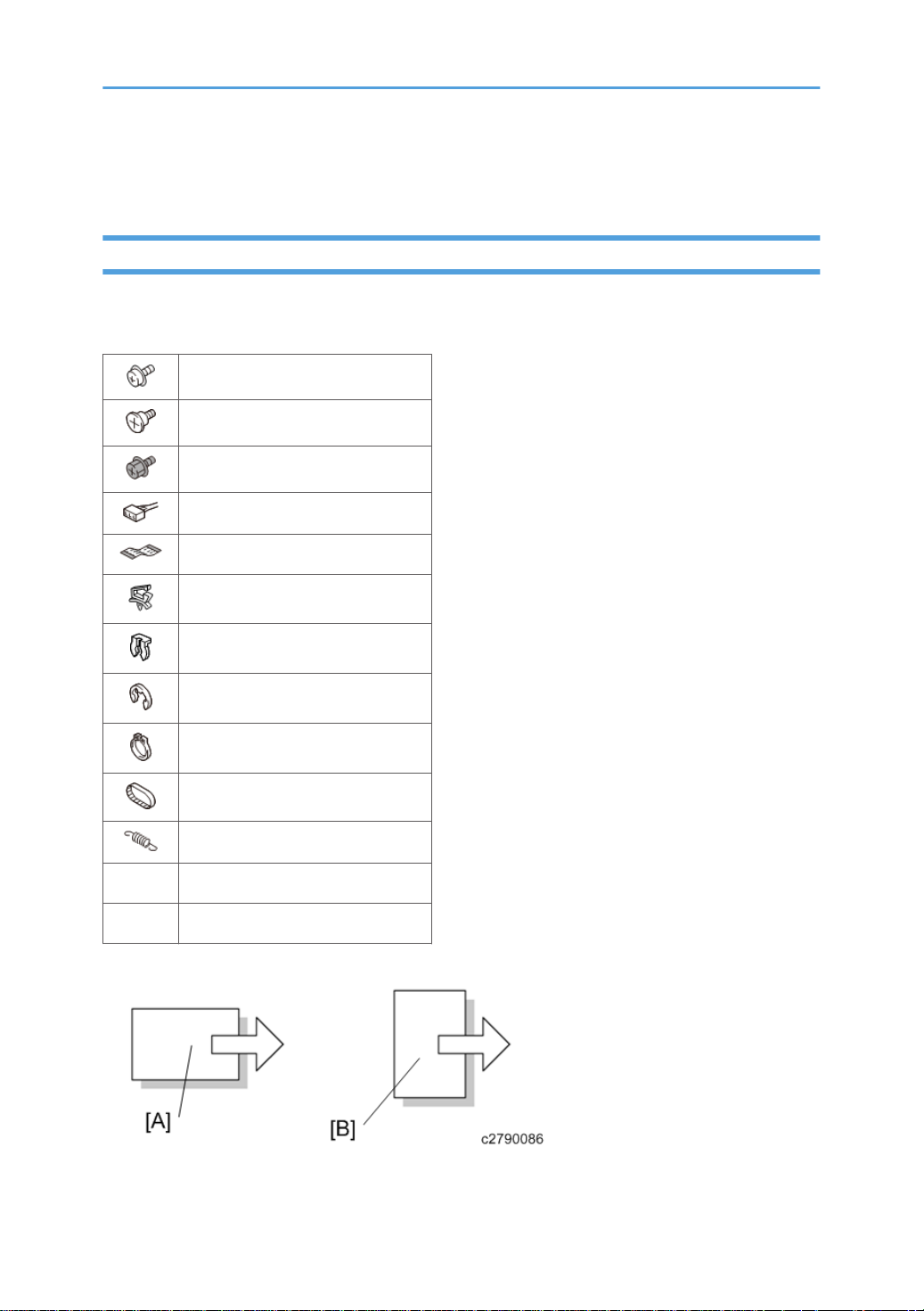
This manual uses several symbols and abbreviations. The meaning of those symbols and abbreviations
are as follows:
Screw
Shoulder screw
Black screw (TCRU)
Connector
FFC (Flat Film Connector)
Harness clamp
Clip
E-ring
C-ring
Timing belt
Spring
SEF Short Edge Feed
LEF Long Edge Feed
[A] Short Edge Feed (SEF)
1
Page 4

[B] Long Edge Feed (LEF)
Trademarks
Intel and Core are trademarks of Intel Corporation in the U.S. and / or other countries.
Google Chrome and Android are trademarks of Google Inc.
iOS® is a registered trademark or trademark of Cisco Systems, Inc. and/or its affiliates in the United
States and certain other countries.
iPhone, iPad, Mac OS, and Safari are trademarks or registered trademarks of Apple Inc., in the United
States and other countries.
Firefox is a registered trademark of the Mozilla Foundation.
Oracle and Java are registered trademarks of Oracle and/or its affiliates. Other names may be
trademarks of their respective owners.
DisplayPort and VESA are registered trademarks of Video Electronics Standards Association in the U.S.
and/or other jurisdictions.
VGA is a trademark of International Business Machines Corporation in the United States, other
countries, or both.
Crestron and RoomView are trademarks or registered trademarks of Crestron Electronics, Inc.
Microsoft, Windows, Internet Explorer, Excel, and PowerPoint are either registered trademarks or
trademarks of Microsoft Corporation in the United States and / or other countries.
The proper name of Internet Explorer 8 is Windows® Internet Explorer® 8.
The proper names of the Windows operating systems are as follows:
• The product names of Windows 7 are as follows:
Microsoft® Windows® 7 Home Premium
Microsoft® Windows® 7 Professional
Microsoft® Windows® 7 Ultimate
Microsoft® Windows® 7 Enterprise
• The product names of Windows 8 are as follows:
Microsoft® Windows® 8
Microsoft® Windows® 8 Pro
Microsoft® Windows® 8 Enterprise
• The product names of Windows 8.1 are as follows:
Microsoft® Windows® 8.1
Microsoft® Windows® 8.1 Pro
Microsoft® Windows® 8.1 Enterprise
2
Page 5

Microsoft product screen shots reprinted with permission from Microsoft Corporation.
Other product names are the trademarks or registered trademarks of each company.
3
Page 6

TABLE OF CONTENTS
Symbols, Abbreviations and Trademarks.........................................................................................................1
Symbols, Abbreviations................................................................................................................................. 1
Trademarks..................................................................................................................................................... 2
1. Product Information
Product Overview............................................................................................................................................... 7
Controller........................................................................................................................................................ 7
Controller Box........................................................................................................................................7
Capture Box...........................................................................................................................................8
Pen Sensor Kit................................................................................................................................................. 9
Pen Sensor..............................................................................................................................................9
Electronic Pen.........................................................................................................................................9
Points Changed from the Previous Model (Controller Not Mounted)......................................................... 10
Differences from When the D6500 is Used Alone................................................................................... 10
Machine Codes and Peripherals Configuration............................................................................................11
Product List....................................................................................................................................................11
Main Unit............................................................................................................................................. 11
Option..................................................................................................................................................11
2. Installation
Installation Requirements................................................................................................................................. 13
Main Unit Installation.......................................................................................................................................14
3. Replacement and Adjustment
Special Tools.................................................................................................................................................... 15
Controller.......................................................................................................................................................... 16
Controller Box.............................................................................................................................................. 16
SSD............................................................................................................................................................... 17
Reconfiguring the Language Settings................................................................................................ 19
Capture Box................................................................................................................................................. 22
Capture Board............................................................................................................................................. 23
Pen Sensor Kit...................................................................................................................................................26
Receiving Module........................................................................................................................................26
USB Cable....................................................................................................................................................26
4. System Maintenance
System Update................................................................................................................................................. 29
4
Page 7

System Update Procedure...........................................................................................................................29
Export/Import of Application Settings............................................................................................................30
Items Subject to Export/Import...................................................................................................................30
File Type........................................................................................................................................................31
Export Procedure......................................................................................................................................... 31
Import Procedure......................................................................................................................................... 33
Breaking the SSD............................................................................................................................................. 36
Service Mode................................................................................................................................................... 39
Service Mode...............................................................................................................................................39
Points Changed on the Service Settings Menu................................................................................. 39
Outline..................................................................................................................................................40
How to Enter the Service Mode.........................................................................................................40
Device Manager..........................................................................................................................................42
Display Color Patterns................................................................................................................................. 43
Display Touch Keyboard.............................................................................................................................44
Simple CAN Bus.......................................................................................................................................... 44
Initialize Administrator Password................................................................................................................45
Windows Activation.................................................................................................................................... 46
License Activation via the Internet......................................................................................................46
License Activation by Phone...............................................................................................................47
5. Troubleshooting
Error Messages................................................................................................................................................ 51
Error Messages during the System Startup................................................................................................51
Error Messages Related to Drawing Strokes.............................................................................................52
Error Messages Related to Sharing the Screen.........................................................................................53
Error Messages When Saving a PDF File.................................................................................................. 54
Error Messages Related to Configuration..................................................................................................58
Error Messages Related to Web Pages.....................................................................................................60
Error Messages When Using the Device as a Monitor............................................................................ 61
Error Messages Related to File Reading....................................................................................................62
Error Messages Related to Remote Whiteboard Sharing........................................................................ 65
Error Messages Related to Network.......................................................................................................... 67
Error Messages Related to RICOH e-Sharing Box................................................................................... 69
5
Page 8

Error Messages Related to Remote Desktop Software............................................................................. 71
Other Error Messages................................................................................................................................. 73
Error Messages for iPad Application......................................................................................................... 77
Troubleshooting................................................................................................................................................78
Defects in the Display Manual Operation Buttons....................................................................................78
Defects in the Display.................................................................................................................................. 78
Defects in the Capture Board......................................................................................................................78
Defects in the Electronic Pen....................................................................................................................... 79
If the System Cannot Start Up......................................................................................................................... 81
IWB Network Environment Check Tool..........................................................................................................82
Outline.......................................................................................................................................................... 82
Diagnostic Content...................................................................................................................................... 82
How to Use the Tool.................................................................................................................................... 83
Beforehand.......................................................................................................................................... 83
Operation on the Server Side............................................................................................................ 83
Operation on the Client Side............................................................................................................. 86
6
Page 9
1. Product Information
Product Overview
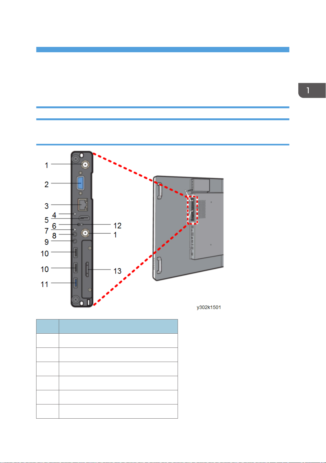
Controller
Controller Box
No. Name
1 WiFi antenna
2 RS232C
3 Ethernet (10/100/1000 Mbps)
4 POWER indicator
5 HDMI
6 RESET button
7
Page 10
1. Product Information
No. Name
7 HDD indicator
8 Audio output (line)
9 Audio output (mic)
10 USB2.0
11 USB3.0
12 Power button
13 2.5” SATA HDD tray
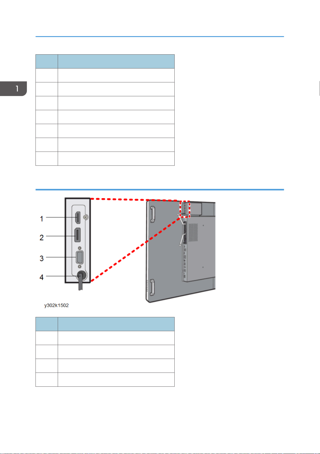
Capture Box
No. Name
1 HDMI input
2 Display Port input
3 VGA input
4 USB3.0 output cable
8
Page 11
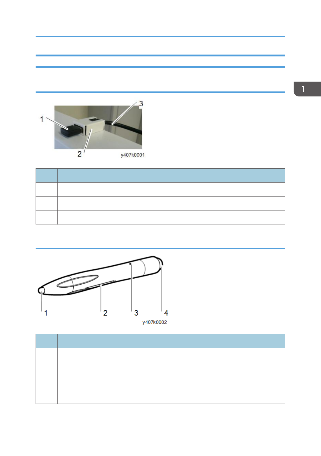
Pen Sensor Kit
Pen Sensor
No. Name
1 Receiving module
2 Receiving module bracket
Product Overview
3 USB cable
Electronic Pen
No. Name
1 Pen nib
2 Battery cover
3 Power indicator
4 Pen bottom
9
Page 12

1. Product Information
Points Changed from the Previous Model (Controller Not Mounted)
Differences from When the D6500 is Used Alone
• When the controller is mounted, the network settings on the main unit (remote settings of the OSD
menu) cannot be used.
If the controller box is mounted, the control setting is automatically from RS-232C; therefore,
control via LAN is disabled (the LAN port on the main unit cannot be used.)
• Touch-panel operation of a computer through the USB cable is disabled.
10
Page 13
Machine Codes and Peripherals Configuration
Machine Codes and Peripherals Configuration
Product List
Main Unit
Brand name Product code
Ricoh Interactive Whiteboard D6500 North America/Latin America: Y302-17
Europe/Asia: Y302-27
Ricoh Interactive Whiteboard D8400 North America/Latin America: Y303-17
Europe/Asia: Y303-27
Option
Brand name Product code
Ricoh Interactive Whiteboard Stand Type 3 Y408-17, 18
Ricoh Interactive Whiteboard Controller
Type 1
Ricoh Interactive Whiteboard Controller
Custom-build Type 1 for Windows
Ricoh Interactive Whiteboard Pen Sensor Kit
Type 2
Ricoh Interactive Whiteboard Remote License
Type 1
North America/Latin America: Y406-17
Europe/Asia: Y406-27
North America/Latin America: Y406-67
Europe/Asia: Y406-57
Y407-17
Y401-17
11
Page 14

1. Product Information
12
Page 15

2. Installation
Installation Requirements
See the installation procedures in the service manual for the main unit for details (Main).
13
Page 16

2. Installation
Main Unit Installation
See the installation procedures in the service manual for the main unit for details (Main).
14
Page 17
3. Replacement and Adjustment
Special Tools
The following tools are required.
No. Item Note
1 USB flash drive For system update
2 Nutdriver For replacing the capture box
3 Phillips screwdriver No. 0 For replacing the SSD
15
Page 18
3. Replacement and Adjustment
Controller
• Turn OFF the main power switch before disassembly.
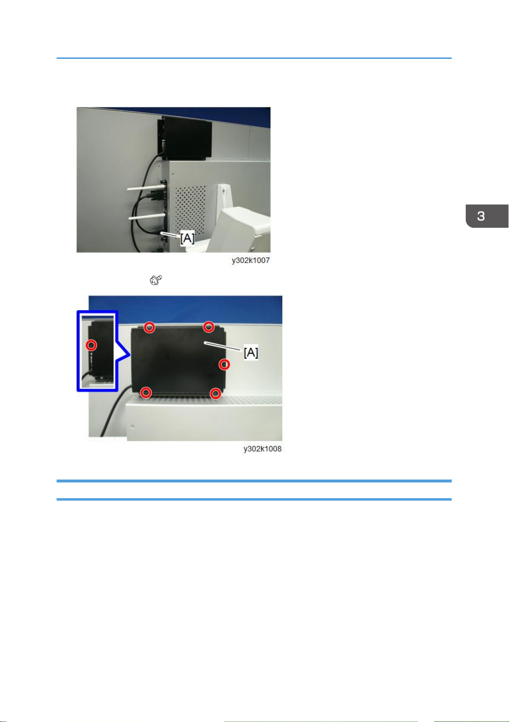
Controller Box
• This part can be removed without removing the optional stand.
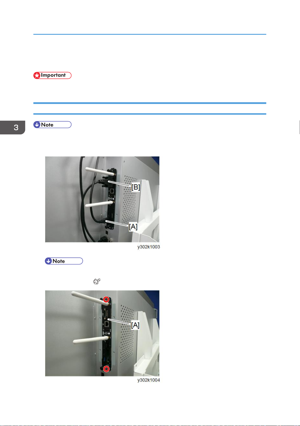
1. USB cable [A] and RS-232C cable [B].
16
• RS-232C cable is only for D6500.
2. Controller box [A] ( x2).
Page 19
Controller
• When installing the new controller box, be sure to perform Windows activation (p.46) in Service
mode.
SSD
• If the SSD is replaced, the system language will be automatically changed to Japanese. See
"Reconfiguring the Language Settings" (p.19).
• When you will replace the SSD and must return the settings to their previous values, make a note of
the following settings before you remove the SSD. If you did not change the default settings, this
step is not necessary.
• Administrator password
• Network settings
• Time settings
• Language settings
• Remote license registration
• E-mail transmission server settings
• E-mail address book registration
• This part can be removed without removing the optional stand.
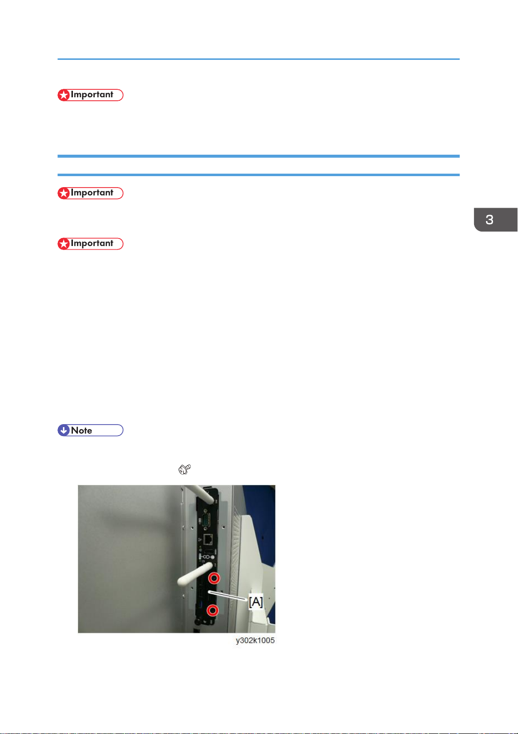
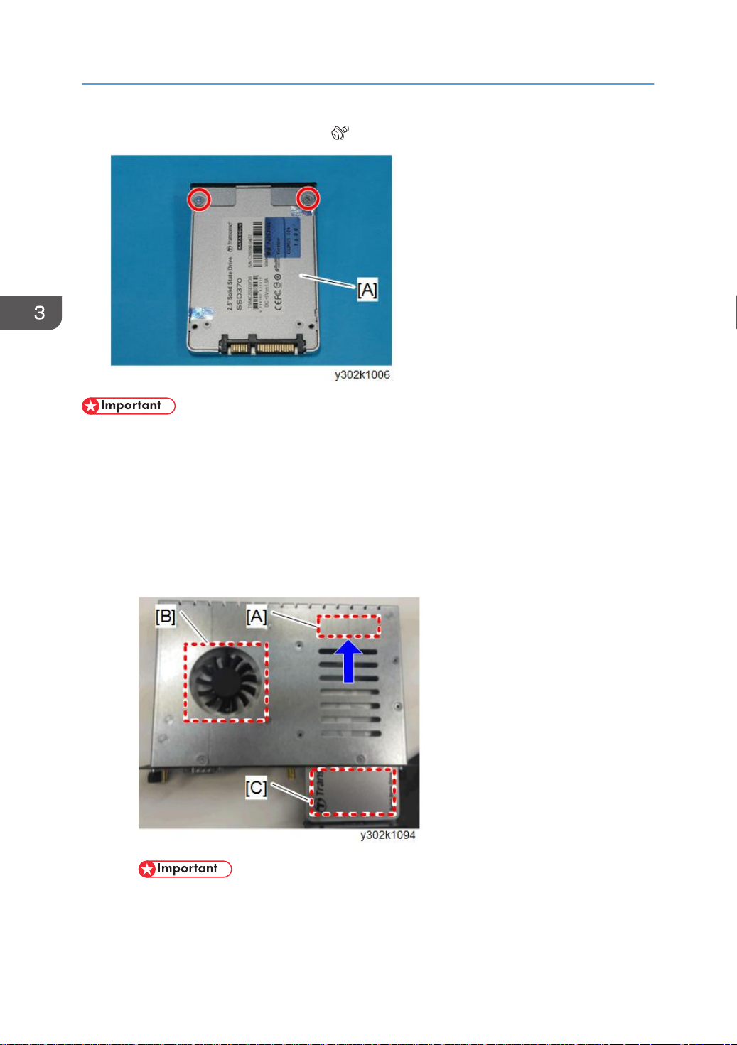
1. SSD with the cover [A] ( x2).
17
Page 20
3. Replacement and Adjustment
2. Remove the SSD [A] from the cover ( x2).
• After replacing, be sure to perform Windows activation (p.46) in Service mode.
Connecting the SSD Firmly
Loose connection of the SSD with the controller box may cause unusual startup of the machine.
Insert the SSD so that the SATA connector [A] is connected firmly, as shown below.
1. Place the controller box facing the fan [B] upward.
2. Slide and insert the SSD with the surface of the SSD [C] facing up, along with the
inside plate, in the direction of the arrow.
18
• If something doesn’t feel right when the SSD being inserted, remove and reinsert the
SSD.
• If the SSD is forcibly inserted, the connector of the controller box may be damaged.
Page 21
Controller
RTB 5
Changed
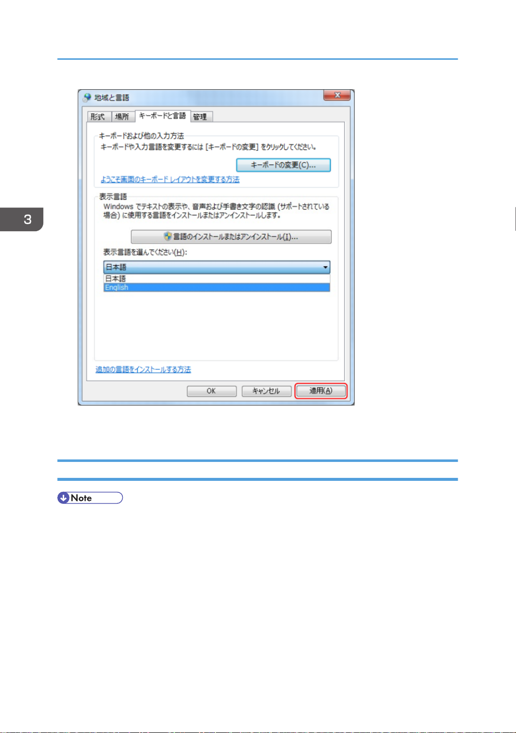
Reconfiguring the Language Settings
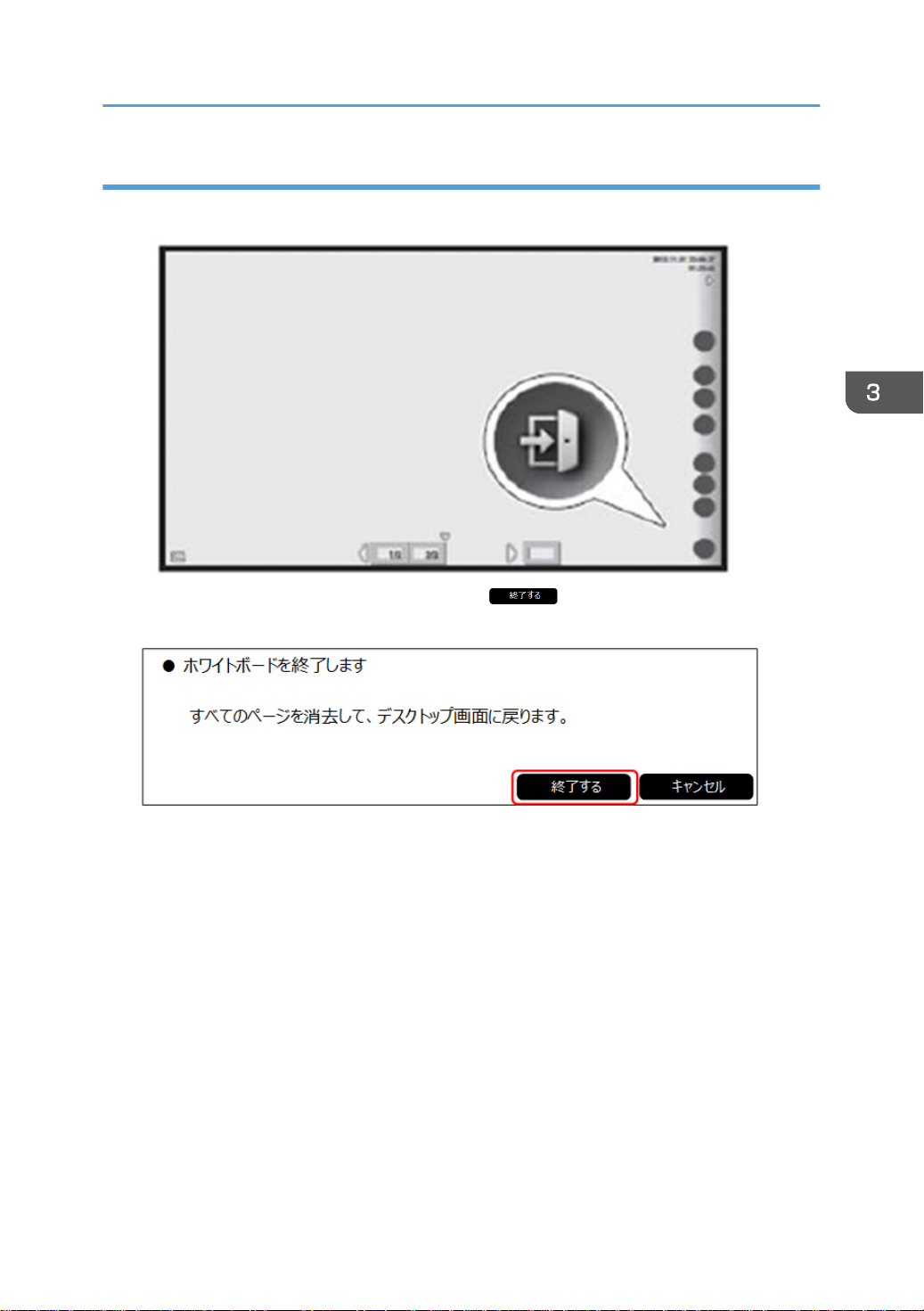
1. Tap and hold the [Close] icon for a few seconds with the tip of the pen.
2. When the following dialog box appears, tap [ ]. The interactive whiteboard will
close.
3. Double-tap the [Administrator Settings] icon. A login dialog box for the Administrator
Settings will appear.
19
Page 22
3. Replacement and Adjustment
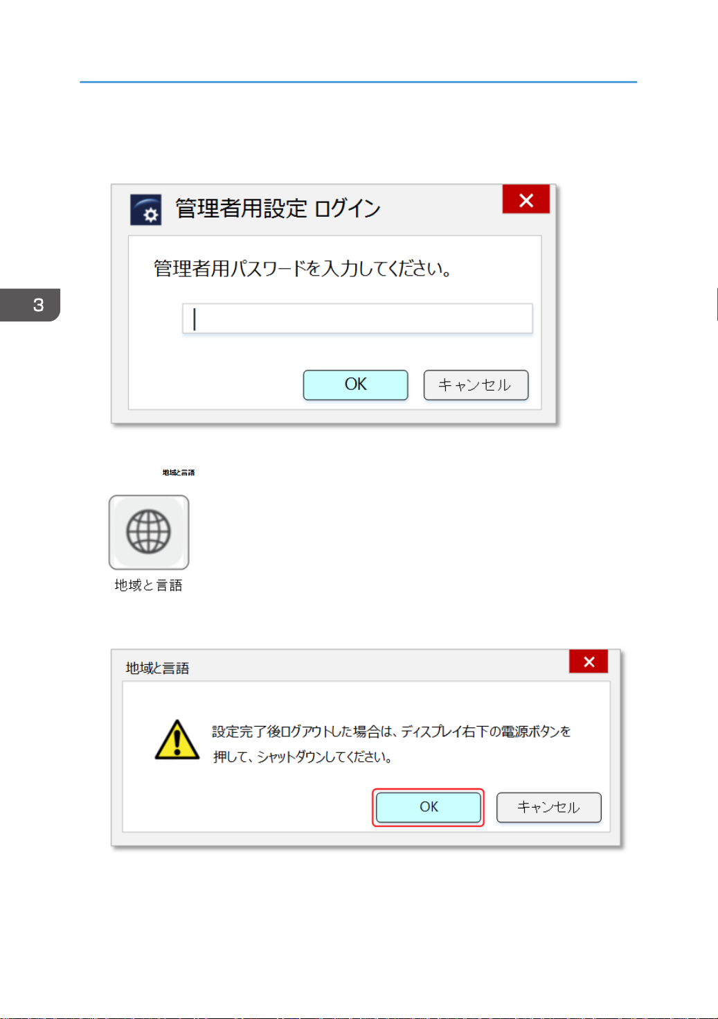
4. Tap the password field to make the touch keyboard appear. Then, input the administrator
password.
5. Tap [OK]. The Administrator Settings dialog will appear.
6. Tap the [ ] icon. (means "Region and Language")
7. The following dialog box will appear. Tap [OK].
20
Page 23
Controller
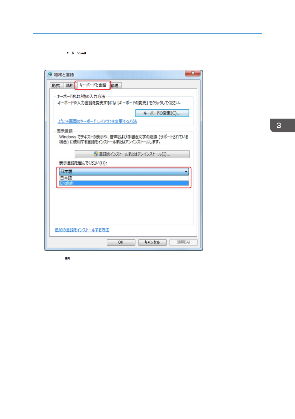
8. Tap the [ ] tab (means "Keyboard and Languages") and choose the preferred
display language from the dropdown list.
Tap the [ ] button. (means "Apply") Then, reboot the IWB.
21
Page 24
3. Replacement and Adjustment
22
9. Confirm that the display language has been changed to the language that was selected.
Then, change other settings as necessary.
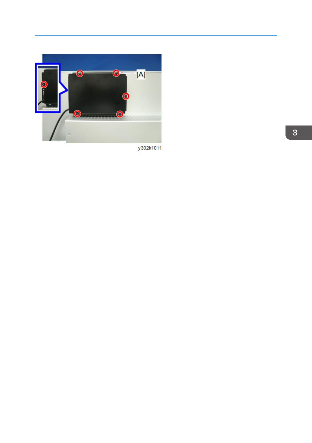
Capture Box
• This part can be removed without removing the optional stand.
Page 25
1. Remove the USB cable [A] from the controller box.
2. Capture box [A] ( x6).
Controller
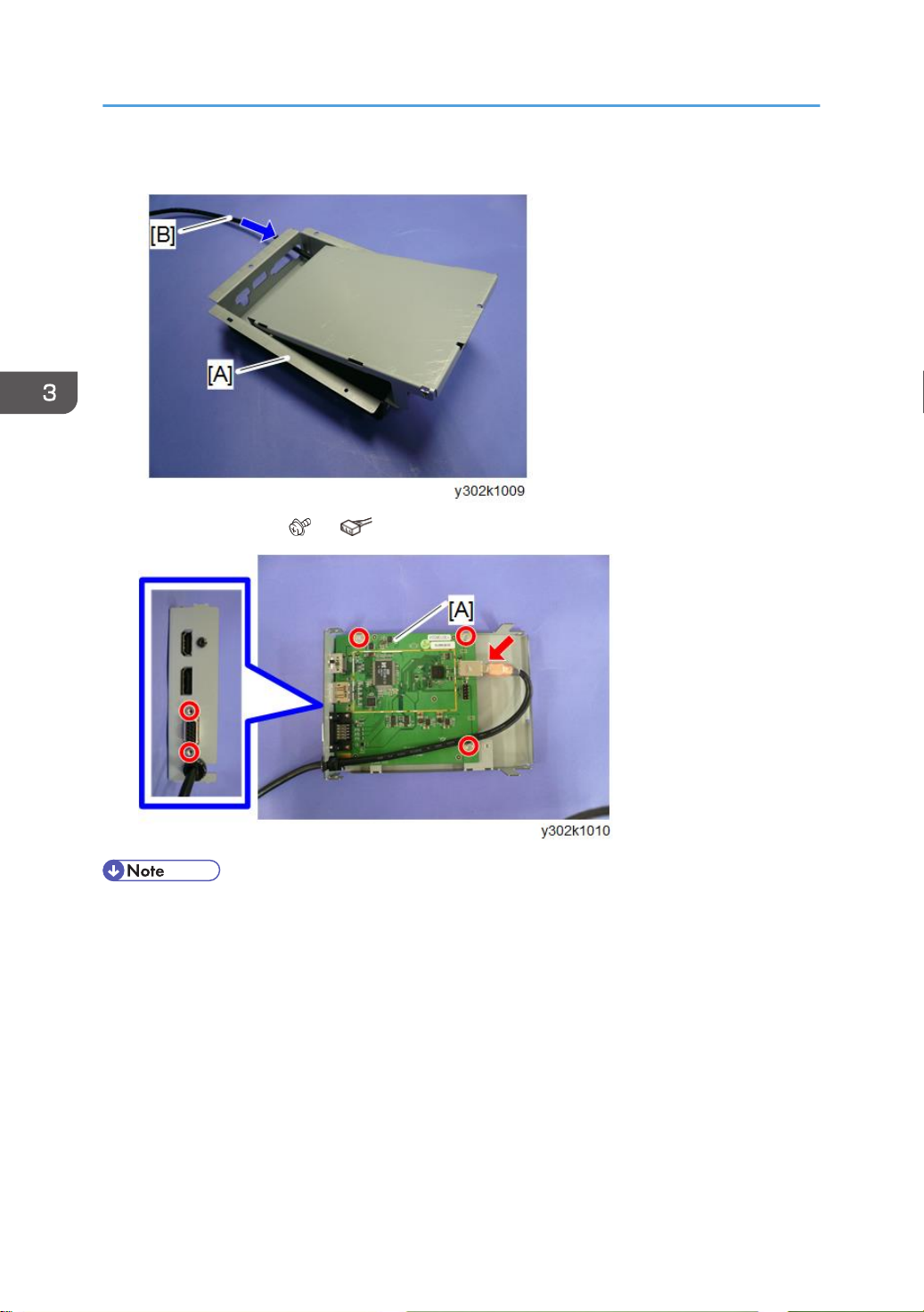
Capture Board
1. Capture box (p.22).
23
Page 26
3. Replacement and Adjustment
2. Pull the USB cable [B] out from the box [A] and remove the cover.
3. Capture board [A] ( x5, x1).
24
• To attach the capture box, fasten the screw [A] first.
Page 27
Controller
25
Page 28

3. Replacement and Adjustment
Pen Sensor Kit
• Turn OFF the main power switch then perform the procedure below.
Receiving Module
• The electronic pen and receiving module are paired. If the receiving module is changed, also
change the electronic pen.
1. Remove the receiving module [B] from the connector [A] of the USB cable.
26
USB Cable
• If the receiving module is attached to the main unit with the magnet, the procedure below is not
required.
1. Remove the receiving module. (p.26)
Page 29

2. Remove the USB cable [A] ( x2).
3. Remove the receiving module bracket [A] ( x2).
Pen Sensor Kit
27
Page 30

3. Replacement and Adjustment
4. Remove the USB cable [B] from the receiving module bracket [A].
28
Page 31

4. System Maintenance
System Update
System Update Procedure
1. Download and unzip the update file (RICOH_Iwb_D6500.zip).
2. Save the file generated in step 1 (RIWB_1.*.**.zip) into the root directory on a USB flash
drive and connect the USB flash drive to the D6500.
3. Execute the system update for administrator setting application on the D6500.
4. Select the target update file on the list of files available to update.
5. Press [OK] to start the update process.
6. When the update is done, the system automatically reboots and the white board
application starts up.
• Automatic updating is enabled via the network.
29
Page 32

4. System Maintenance
Export/Import of Application Settings
This machine can import/export the device setting information using a USB flash drive.
Since the contents of the exported/imported file are encrypted, they cannot be checked.
Items Subject to Export/Import
You can back up the settings and recover the former settings with the backup file.
The following items can be exported to a USB flash drive:
• Network Settings
• Time settings
• Region and language settings
• SMTP Server Settings
• Email Address Book settings *1
• Contact List settings *1
• Shared Folder List settings
• System Settings
• Security Settings
• Print Settings
• Version Information
• Wireless Network Settings
*1 No history can be backed up.
The following setting information can be excluded from importing or exporting.
• Display color profile
• System Settings
• Whiteboard Location Name
• Network Settings
• Network Auto Settings
• IP Address
• Subnet Mask
• Default Gateway
• Preferred DNS server setting
30
• Alternate DNS server setting
• Use Synchronous Function on Device Configuration
Page 33

Export/Import of Application Settings
The following setting information that is specific to each device cannot be synchronized:
• Remote License
• Administrator Password
File Type
The ZIP file named "iwb-settings-system version-YYYYMMDD-hhmmss.zip" is stored in the root directory
on the USB flash drive.
YYYYMMDD-hhmmss: Export execution date (local time)
Export Procedure
1. Tap [Export Device Configuration] on the Administrator Settings menu.
2. Insert a USB flash drive into the USB port of the main unit
3. Tap [OK] when the following screen comes up.
Export is started.
31
Page 34

4. System Maintenance
4. The following screen is displayed when export completed successfully. Tap [OK].
One of the following screens is displayed when export failed.
32
Page 35

Import Procedure
Export/Import of Application Settings
1. Copy the exported data (ZIP file) to the root of the USB flash drive.
2. Tap [Import Device Configuration] on the Administrator Settings menu.
3. Insert the USB flash drive into the USB port of the main unit.
4. Tap [OK] when the following screen comes up.
33
Page 36

4. System Maintenance
• Check “The following device unique setting value(s) will not be imported” to avoid overwriting
the device’s unique setting value(s).
5. When the following screen is displayed, tap [OK] after selecting the setting file to import.
When [OK] is tapped in the setting file selection screen, it will change to the following screen.
The following screen is displayed when there is no setting file in the root of the USB flash drive. If
[OK] is tapped, it will return to the Administrator Settings menu.
6. When import is completed normally, a dialog to request rebooting is displayed. Tap [OK]
to reboot the main unit.
34
Page 37

Export/Import of Application Settings
7. One of the following screens is displayed when import is failed. If [OK] is tapped, it will
return to the Administrator Settings menu.
35
Page 38

4. System Maintenance
Breaking the SSD
1. Remove the SSD (p.17).
2. Remove the cover from the SSD ( ×4).
3. Remove the board ( ×2).
36
Page 39

4. Break the SATA connectors, using pliers.
• Be sure to break both the left and right connectors.
5. Break the internal board using pliers.
Breaking the SSD
6. Remove the flash IC [A] and break the board further.
37
Page 40

4. System Maintenance
7. Break the flash IC [A], using large nippers.
38
Page 41

Service Mode
Service Mode
Points Changed on the Service Settings Menu
Service Mode
Item D5510
Device Manager Settings Yes Yes
Display Color settings
Yes No
Advanced Sensor Adjustment
Yes No
Advanced Position Adjustment
Yes No
Finger Drawing Mode
Change Electronic Pen ID
Display Color Patterns Yes Yes
Yes No
Yes No
D6500
D8400
Remarks
As the color profile settings for the D6500/
D8400 are made on the main unit, this
function is omitted.
The sensor mechanism is not necessary for
the D6500/D8400, because it is different
from that on the D5510.
The sensor mechanism is not necessary for
the D6500/D8400, because it is different
from that on the D5510.
This mode is omitted, because the pen is
optional for the D6500/D8400.
This function is not required on the D6500/
D8400.
Display Touch Keyboard Yes Yes
Simple CAN Bus Yes Yes
Function Settings Yes Yes
Initialize Administrator Password Yes Yes
Windows Activation No Yes On the D6500/D8400, the OS is changed.
39
Page 42

4. System Maintenance
Outline
The following functions are only for service. They can be set up and checked in the setting window for
services.
Item Contents Purpose of use
Device Manager Settings Checks the hardware
operating state
Display Color Patterns Two or more color patterns
are displayed on the screen.
Display Touch Keyboard Keyboard is displayed. Enter characters on the screen.
Simple CAN Bus You can write lines on the
screen with a finger.
Function Settings Custom-order setting items Not for servicing items
Initialize Administrator
Password
Windows Activation For Windows license
Returns the administrator’s
password to the factory
setting.
activation.
Condition check on the position
sensor, capture board, etc.
Check for display abnormality in the
LCD panel
This is used to isolate defects in the
position sensor.
When the customer has lost his/her
password.
When the SSD is replaced, perform
after replacement.
How to Enter the Service Mode
1. Touch and hold the [Close] icon.
40
Page 43

2. Tap [Close].
3. Double-tap the [Settings] icon.
4. Touch and hold [Version Information] for five seconds.
Service Mode
5. Tap the [Search] icon.
41
Page 44

4. System Maintenance
6. Tap the [ServiceSettings] icon.
7. Enter the password for service "y300kb" in the dialog box and tap [OK].
8. The Service Setting Menu is displayed.
Device Manager
1. Tap [Device Manager Settings] on the Service Settings Menu.
42
Page 45

Service Mode
2. The hardware operation confirmation screen shown below is displayed, on which the
status of each device can be checked.
Display Color Patterns
1. Connect a USB keyboard to the USB terminal of the main unit.
2. Tap [Display Color Patterns] on the Service Settings Menu.
3. Change the color pattern, using the F1 to F7 keys on the USB keyboard.
4. Press the ESC key to finish the display color pattern check.
43
Page 46

4. System Maintenance
Display Touch Keyboard
1. Tap [Display Touch Keyboard] on the Service Settings Menu.
Simple CAN Bus
1. Tap [Simple CAN Bus] on the Service Settings Menu.
2. Make sure that you can draw a line with your finger.
44
Page 47

Initialize Administrator Password
1. Tap [Initialize Administrator Password] on the Service Settings Menu.
2. Tap [Initialize].
Service Mode
45
Page 48

4. System Maintenance
Windows Activation
License Activation via the Internet
1. Tap [Window Activation] on the Service Settings Menu.
2. Tap [Activate].
3. Tap [Close] to finish the activation.
46
Page 49

4. Tap [Close].
If activation failed, the screen below is displayed.
Service Mode
If error code 80072EE7 is displayed, check the connection with the Internet and perform license
activation again.
For any error code other than above, refer the URL below to take the appropriate
countermeasures.
URL: http://windows.microsoft.com/en-us/windows-8/activation-errors
License Activation by Phone
1. Tap [Windows Activation] on the Service Settings Menu.
47
Page 50

4. System Maintenance
2. Tap [Activate by Phone].
3. Select the nearest location, and then tap [Next].
48
4. Call the phone number displayed.
5. Enter the installation ID listed on the screen into phone’s keypad.
• Write down the confirmation ID given by the phone guidance.
Page 51

6. Enter the confirmation ID on the screen, and then click [Next].
7. Tap [Close] to finish the activation.
Service Mode
8. Tap [Close].
49
Page 52

4. System Maintenance
If activation failed, the screen below is displayed.
Enter the confirmation number again.
50
Page 53

5. Troubleshooting
Error Messages
Error Messages during the System Startup
Message Error Code Cause Solution
Instead of pressing the
power button normally, one
of the following actions was
performed to force the
machine to shut down the
last time it was running:
A fatal error has occurred. -
• Pressing and holding
down the power
button.
• Turning off the main
power.
• Disconnecting the
power cable.
• Quickly press and
release the power
button on the front
of the display.
When the machine
shuts down, press
the power button
again to restart the
machine.
• If the message
appears again,
retrieve logs and
system settings.
(Logs and system settings
can be retrieved through
[Log Collection] in
“Administrator Settings”.
Send the retrieved data
to the service support
desk to analyze the
machine status.)
51
Page 54

5. Troubleshooting
Error Messages Related to Drawing Strokes
Message Error Code Cause Solution
The number of handwritten
entries exceeds the limit.
Page [xxx] and after will be
imported as images.
Nothing more can be
entered because the total
number of entries on the
whiteboard has reached the
limit.
Nothing more can be
entered because the total
number of entries on the
whiteboard has reached the
limit. Reduce the total
number of entries by
deleting handwritten
entries/texts/lines/
graphics/pages.
1004-1005
2014-2001
1014-2002
Handwritten pages/entries
exceed the upper limit.
• The total number of
entries on the page
exceeds the limit entry
count per one page.
• 3000 strokes/texts/
shapes have been
written in the pages
being shown on the
screen.
• The total number of
entries (strokes/texts/
shapes) in all pages
reaches 9000.
• Delete unnecessary
pages containing
strokes.
• Delete unnecessary
strokes.
Delete unnecessary
pages containing
handwritten, and delete
again.
• Delete unnecessary
stroke in the page
displayed, or add a
new page.
• Delete a page itself
or strokes in the
page.
52
Page 55

Error Messages Related to Sharing the Screen
Message Error Code Cause Solution
Cannot connect because
the software version is
different. Update the host
terminal and the
participating terminals to
the latest version.
Cannot continue remote
whiteboard.
A communication error has
occurred. Restart the remote
whiteboard.
-
-
The version of the host
whiteboard does not match
the version system of
participating whiteboard.
No response from the client
terminal even when it takes
30 seconds.
Error Messages
• Update the system.
For details about
how to update the
system, refer to the
operating
instructions.
• Use compatible
mode.
Restart the remote
whiteboard.
A communication failure
has occurred.
Save the created page and
restart the application.
A communication timeout
has occurred.
Possible causes may be as
follows.
- Not connected to the
network
- A failure has occurred on
the host terminal
• A timeout occurred
while you were
opening a whiteboard
-
-
session.
• An internal error
occurred while you
were using remote
whiteboard.
The network cable is not
connected or is broken.
Save the page as
needed. Next, quickly
press and release the
power button on the front
of the display. When the
machine shuts down,
press the power button
again to restart the
machine.
Check that the network
cable is connected or is
not broken.
53
Page 56

5. Troubleshooting
Message Error Code Cause Solution
• The network cable is
Cannot continue remote
whiteboard because of a
communication error
Cannot delete the page. Try
again later.
Cannot add the page(s). -
-
-
• The IP address is not
• No IP address can be
The file that you want to
delete is being
downloaded.
A network failure may
occur on a device using
remote white board.
Error Messages When Saving a PDF File
Message Error Code Cause Solution
No captured page is
There is no data to save.
Either add a page or make
a handwritten entry and
then try again.
1012-2007
created.
No handwritten stroke
exists.
No input image from PC
exists.
not connected.
set.
obtained over DHCP
Check the network status
and re-open the session.
For details about how to
configure the Network
Settings, refer to the
operating instructions.
Wait for a while and then
try to delete the page
again.
Wait for a while and then
try to add the page
again.
Save a data after doing
the following.
• Create a captured
page.
• Draw a stroke on
the screen page.
• Display an image
from a computer on
the screen page.
54
Cannot save temporarily
saved file.
The number of temporarily
saved files has reached the
limit.
Contact your administrator.
1012-2008
The number of temporarily
saved files reaches the limit
(1000 files).
Ask the whiteboard’s
administrators for
deleting some
temporarily saved files
through “Administrator
Settings”.
Page 57

Error Messages
Message Error Code Cause Solution
Cannot save temporarily
saved files. Insufficient free
space in the temporary save
folder.
Contact your administrator.
You do not have the
authority to write to the
mounted USB memory
Failed to send the email
because the size of the
attached file is too large.
Use the [Save in USB
Memory] function.
1012-2009
-
-
The temporarily saved file
size reaches the upper limit
(10GB).
You do not have the
authority to write to the USB
flash memory device.
The attempt to send the email failed because the size
of the attached file exceeds
the set limit.
Ask the whiteboard’s
administrators for
deleting some
temporarily saved files
through “Administrator
Settings”.
Configure the USB flash
memory device
properties to allow
information to be written.
• Reduce the file size
by deleting
unnecessary files
from the whiteboard
pages.
• Save temporarily or
save it onto a USB
flash drive.
55
Page 58

5. Troubleshooting
Message Error Code Cause Solution
Failed to send the email.
The following are possible
causes.
Failed to connect to the
SMTP server.
Failed to authenticate with
the SMTP server.
The operation to connect to
the SMTP server has timed
out.
• Check whether the
network cable is
connected, or the
cable is broken.
• The network cable is
not connected, or the
cable is broken.
• There is an error in the
Network Settings (such
as the DNS).
• There is an error in the
SMTP Server Settings
-
(IP address, host
name, or port
number).
• There is an error in the
authentication settings
for the SMTP server
(authentication,
account, or
password).
• Access
Administrator
Settings and check
the Network
Settings. For details
about how to
configure the
Network Settings,
see Configuring
Network Settings.
• Access
Administrator
Settings and check
the SMTP Server
Settings. For details
about how to
configure the SMTP
Server Settings,
refer to the
operating
instructions.
56
Failed to create the PDF file.
Please call service.
Retrieve logs and system
settings.
(Logs and system settings
• Insufficient memory
-
available.
• A system error occurs.
can be retrieved through
[Log Collection] in
“Administrator Settings”.
Send the retrieved data
to the service support
desk to analyze the
machine status.)
Page 59

Error Messages
Message Error Code Cause Solution
The meeting code is
incorrect.
Enter the correct meeting
code.
Cannot save.
Try again after checking the
USB memory mount, the
free space and if it has write
authorization.
Change the file name.
Try again after changing
the file name or deleting the
file with the same name.
Failed to save the file. Try
again after checking the
USB memory connection,
free disk space, the
presence of write protect
etc.
-
-
1012-2011
-
Incorrect meeting code is
entered.
• Disconnecting the USB
flash drive during
saving.
• No available capacity
in the USB flash drive.
• No permission to write
to the USB flash drive.
Cannot save the specified
file name because the file
name has already been
used from the branch
number 1 to 100.
The USB flash drive is
disconnected during
reading.
Enter the meeting code
that has been entered
when saving temporarily.
• Allocate sufficient
space for the USB
flash drive.
• Add permission to
write to the USB
flash drive.
Delete unnecessary
branch number of file(s),
or change the file(s) to
other file name. Save the
file to other location.
Do not disconnect USB
flash drive during
reading
57
Page 60

5. Troubleshooting
Error Messages Related to Configuration
Message Error Code Cause Solution
Cannot import because the
email address format is
incorrect.
Use the correct email
address format.
-
The format of the e-mail
address is invalid.
Check whether any of the
following apply:
• The e-mail address
is left blank.
• More than 64
characters are used
for the local block
of the email
address.
• More than 255
characters are used
for the domain of
the e-mail address.
• More than 256
characters are used
for the e-mail
address.
58
Page 61

Message Error Code Cause Solution
Cannot import because the
IP address format is
incorrect.
Use the correct IP address
format.
Error Messages
Check whether any of the
following apply:
The IP address is left
blank.
The IP address is not
composed of four parts,
each separated by a
period, which contain
three or fewer single-byte
The file to be imported
-
contains an IP address with
an invalid format.
digits.
The four parts of the IP
address, each separated
by a period, contain
three or fewer single-byte
digits with an invalid
value.
Cannot import because the
IP address format is
incompatible.
Check the IP address and
reset it.
More than 256 digits are
used.
Digits that start with 0 or
00 are used
The file to be imported
contains an IP address with
-
an invalid value.
Check whether the file
contains an IP address
(such as 0.0.0.0 or
127.0.0.1) configured
for a specific purpose.
59
Page 62

5. Troubleshooting
Message Error Code Cause Solution
Instead of pressing the
power button normally, one
of the following actions was
Returned to factory defaults.
Make the settings again on
administrator settings.
The configuration file may
be corrupted if the main
power was forcibly
switched off.
-
performed to force the
machine to shut down the
last time it was running:
Error Messages Related to Web Pages
Message Error Code Cause Solution
The number of simultaneous
connections exceeds the
limit.
Try again later.
-
The number of devices
accessing the Web page
and viewing remote
whiteboard has already
exceeded the limit.
• Pressing and holding
down the power
button.
• Turning off the main
power.
• Disconnecting the
power cable.
Open “Administrator
Settings” and reconfigure
the machine settings. For
details about
“Administrator Settings”,
see Operating
Instructions.
Wait until one of the
devices finishes viewing
remote whiteboard, and
then try to connect to the
remote whiteboard.
60
The passcode is not correct. -
Incorrect passcode is
entered.
Enter the correct
passcode shown on the
left/right upper part of
the host whiteboard.
Page 63

Error Messages
Message Error Code Cause Solution
The meeting code is
incorrect
Enter the correct meeting
code.
• The specified meeting
code is incorrect.
• There is no temporarily
saved file associated
with the specified
meeting code.
-
• Reboot the video
conferencing
device.
• Reconnect the USB
cable for the video
conference device
and your computer.
• If the message
appears again,
retrieve logs and
system settings.
(Logs and system
settings can be
retrieved through
[Log Collection] in
“Administrator
Settings”. Send the
retrieved data to the
service support desk
to analyze the
machine status.)
Error Messages When Using the Device as a Monitor
Message Error Code Cause Solution
• The resolution of the
Cannot display the
externally inputted image.
An error has occurred on
the captured device.
Reconnect the cable.
Cannot display the
externally inputted image.
Change the resolution or
the refresh rate.
1002-2003
1002-2004
computer which you
are attempting to
display is
unsupported.
• A VGA cable does not
connect firmly.
The resolution of the
computer which you are
attempting to display is
unsupported.
• Change the
computer’s
resolution to a
supported one.
• Reconnect the
display cable.
Change the computer’s
resolution to a supported
one.
61
Page 64

5. Troubleshooting
Message Error Code Cause Solution
Cannot display because of
copyright protected (HDCP)
contents. Cannot display
copyright protected
contents on HDMI Input 1.
Connect to the external
input terminal: HDMI Input
2 and click [Enter/Input].
*Cannot use whiteboard
function on HDMI Input 2.
Cannot display because of
copyright protected (HDCP)
contents. Cannot display
copyright protected
contents on DisplayPort
Input Connect to the
external input terminal:
HDMI Input 2and click
[Enter/Input] .
1002-2007
1002-2007
The attempt to open a
copyright protected
contents failed.
Display a content that is
not copyright protected.
* Cannot use whiteboard
function on HDMI Input 2
Error Messages Related to File Reading
Message Error Code Cause Solution
Cannot add all the pages.
Unable to add all the
pages because the page
limit ([xxx] pages) has
been reached while
reading. [xxx] page(s) has
been added.
Do you want to continue?
1004-1001
Some pages cannot be
added because the page
count of the PDF exceeds
the page count that can be
added.
Select [Yes] to read, or
select [No] to select other
PDF.
62
Page 65

Message Error Code Cause Solution
Cannot add all of the
pages
Set a page size from 100 x
148 mm to A0.
Error Messages
A file import failure
-
occurred because the
page size is inappropriate.
Delete unnecessary pages
of the file before it is
converted to an image.
Cannot add all the pages,
added [xxx] pages
Cannot access the file
You do not have
permission to read the file.
Set read permission on the
file and then try again.
Cannot import the file.
Only file sizes up to xxxMB
can be imported. Select a
file under xxxMB.
Cannot import the file
The file may be corrupted.
Check the file and then try
again.
Cannot import the file.
The following are possible
causes.
- The file format is not
PowerPoint.
- The file is corrupted.
- A password is set on it.
Check the PowerPoint file
and then try again.
1004-1002
1004-2006
1004-2008
1004-2015
1004-2016
Since the file is corrupt, an
error occurs during
reading.
The file to be imported has
no permission to read.
The file to be imported
exceeds the upper limit of
file size (100MB).
Since the file is corrupt, an
error occurs during
reading.
• The file format is not
PPT. (ex.: A file that
merely changed the
file extension to .ppt
will be failed to open)
• The PPT file has
password protection.
• The PPT file is corrupt.
Delete unnecessary pages
of the file before it is
converted to an image.
Grant the whiteboard the
permission to read.
Change the file to be
imported to 100MB or
less.
Make sure that the PDF
can open in your PC, and
then try it in the whiteboard
again.
Make sure that the PPT file
can open in your PC, and
try loading the file in the
whiteboard again.
Cannot access the folder.
Access control is set on the
folder. Cancel access
control on the folder and
try again.
1019-2002
• No permission to
access the folder.
• No ownership of the
folder.
Cancel the restriction
applied to the folder, and
then try again.
63
Page 66

5. Troubleshooting
Message Error Code Cause Solution
Cannot access the USB
memory.
The following are possible
causes.
- The USB memory has
been removed.
- The USB memory is
corrupted. Check the USB
memory and then try
again.
1019-2003
• The USB flash drive is
broken.
• The USB flash drive is
not connected.
• Access control is
applied to the USB
flash drive.
• The USB flash drive is
disconnected during
the process.
• The USB flash drive is
broken during the
process
• Replace a new USB
flash drive and then
try again.
• Make sure that the
USB flash drive
connects firmly.
Cannot access the shared
folder.
Cannot access to the
network. Try again later. If
there is no improvement
contact your administrator.
Cannot find the folder.
The following are possible
causes.
- The folder has been
deleted.
- The folder has been
moved.
1019-2005
1019-2006
• Cannot access the
shared folder through
the network.
• The network is busy.
• Access control is
applied to the shared
folder.
• The protocol
providing shared
access is not CIFS
(SMB).
• SMB communication
is restricted in the
network.
• Folder is deleted.
• No folder in the
specified directory.
• Make sure that the
whiteboard connects
to the network, an IP
address is set
properly, and other
computer can access
the shared folder.
• Wait for a while the
whiteboard may be
obtaining the system
information.
• Cancel the restriction
applied to the folder,
and then try again.
• Add a new folder.
• Move to a directory
where folder to be set
exists
64
Select another folder.
Page 67

Message Error Code Cause Solution
Cannot add the page(s).
Error Messages
The number of pages has
reached the limit (100
pages). Delete some pages
and try again.
Cannot import. Try again
after checking the file
format.
1019-2008
-
The number of pages has
reached the upper limit.
• Unusable character is
used in the domain
name.
• The domain name is
null, or has 256
characters or more.
Error Messages Related to Remote Whiteboard Sharing
Message Error Code Cause Solution
Cannot start remote
whiteboard.
A communication error has
occurred. Try again later or
contact your administrator.
-
The Remote whiteboard is
terminated.
Delete pages and try
reading again.
Specify the correct domain
name in the domain list
Start the remote
whiteboard.
Cannot participate in
remote whiteboard because
the passcode is incorrect.
The passcode is incorrect.
Enter the correct passcode.
Remote whiteboard is not
started on the whiteboard's
main unit.
Enter the correct
-
-
Incorrect passcode is
entered.
The remote whiteboard is
not started.
passcode shown on the
left/right upper part of
the host whiteboard.
Start the remote
whiteboard.
65
Page 68

5. Troubleshooting
Message Error Code Cause Solution
Cannot start remote
whiteboard.
The following are possible
causes.
- The network settings are
incorrect
- The network cable is not
connected.
Check the network status
and then try again.
The number of simultaneous
connections exceeds the
limit. Only up to 20
computers can connect to
the whiteboard at the same
time.
Cannot start [xxx] screen
sharing
• The network cable is
not connected.
-
• The IP address is not
set.
• No IP address can be
obtained over DHCP
Only up to 20 computers
-
can connect to the
whiteboard at the same
time.
Check the network status
and re-open the session.
For details about how to
configure the Network
Settings, refer to the
Operating Instructions
Wait until the computer
can connect to the
whiteboard.
The whiteboard has
recognized that a UCS
connects to the whiteboard
through an USB cable, but
the any of the following
• Reboot the UCS.
• Connect the USB
cable again.
occurs:
• If these problems
• The UCS's screen
sharing application
fails to start the screen
-
sharing, and it cannot
be recovered by
restarting the
application or the USB
port for the UCS.
• The UCS’s screen
sharing application
cannot start through
the UCS drive because
persist, retrieve the
log/settings. (Logs
and system settings
can be retrieved
through [Log
Collection] in
“Administrator
Settings”. Send the
retrieved data to the
service support desk
to analyze the
machine status.)
the USB cannot be
recognized.
66
Page 69

Message Error Code Cause Solution
Cannot import the contact
list.
Error Messages
Check the contents of the
file. The last allowed
character of a column and
the first of the next column
must be separated with a
tab character.
-
Error Messages Related to Network
Message Error Code Cause Solution
Cannot continue sending
the email because of a
communication error.
The following are possible
causes.
• The network settings
are incorrect
• The network cable is
not connected Check
the network status and
then try again.
1006-2003
The number of data items
for host whiteboard address
is incorrect.
• The network cable is
not connected.
• The IP address is not
set.
• No IP address can be
obtained over DHCP
Modify the contents of
the contact list file.
• Connect the
network cable to the
whiteboard.
• Assign an available
IP address to the
whiteboard
manually.
No captured page is
There is no data to send.
Either add a page or make
a handwritten entry and
then try again.
Check the proxy settings. - Incorrect proxy setting
1006-2003
created.
No handwritten stroke
exists.
No input image from PC
exists.
• Create a captured
page.
• Draw a stroke on
the screen page.
• Display an image
from a computer on
the screen page.
Configure the proxy
setting properly
67
Page 70

5. Troubleshooting
Message Error Code Cause Solution
Cannot confirm the latest
version. Check the network
status.
Cannot use the host name
because the DNS server is
not set.
Go to network settings in
administrator settings to set
the DNS server.
-
The whiteboard is not
connected to the network.
1001-2509 DNS server is not set.
• Make sure the
network connection.
• Make sure that the
network cable is
connected properly.
Configure the DNS
setting through
“Administrator Settings >
Network Setting”.
Go to network settings in
administrator settings to set
the DNS server.
Cannot access the shared
folder.
The following are possible
causes.
- The network cable is not
connected
- The IP address is not set\r
\n- Cannot obtain the IP
address from DHCP.
Check the network status
and then try again.
1001-2510
1004-2002
The hostname cannot be
resolved from the IP
address.
The whiteboard has an
incorrect network setting.
Enter the correct
hostname.
Make sure the network
setting on the
whiteboard, and then try
again.
68
Page 71

Message Error Code Cause Solution
Cannot access the shared
folder.
The following are possible
causes.
- The settings for the shared
folder are wrong.
- Cannot access the
network.
Try again later.
If there is no improvement
contact your administrator.
1019-2004
• The shared folder does
not work properly.
• The server that
provides folder
sharing does not
connect to the network
properly.
• The protocol providing
shared access is not
CIFS (SMB).
• Incorrect file path to
the shared folder.
• Incorrect username or
password.
• The network cable is
not connected to the
whiteboard properly.
• No IP address assign
to the whiteboard.
• No DNS server is set
to the whiteboard.
Error Messages
• Make sure the
shared folder setting
of the whiteboard.
• Make sure that you
can access the
shared folder
through your PC,
and then try again.
• IP packets cannot
reach to the shared
folder due to a
different subnet.
• SMB communication is
restricted in the
network.
Error Messages Related to RICOH e-Sharing Box
Message Error Code Cause Solution
Cannot import the file.
PDF files from version 1.3 to
1.7 can be imported.\r
\nSelect another PDF file.
1004-2009
The PDF file version you are
importing to the whiteboard
is not from 1.3 to 1.7.
Change the import PDF
file version from 1.3 to
1.7.
69
Page 72

5. Troubleshooting
Message Error Code Cause Solution
Cannot import the file.
Set a page size from 100 x
148 mm to A0.
Cannot import the file.
A password is set on this file
to open the document.
Select another PDF file.
Cannot import the file.
Copying the contents of this
file is not allowed.
Cannot import the file.
Security is set on this file.\r
\nSelect another PDF file.
Cannot import the file. The
file may be corrupted.
Select another PDF file.
1004-2010
1004-2011
1004-2012
1004-2013
1004-2014
The PDF page size you are
importing to the whiteboard
is not in between 100 x
148 mm to A0.
The PDF file you are
importing to the whiteboard
is set a password.
The PDF file you are
importing to the whiteboard
is set a copy protection.
The PDF file you are
importing to the whiteboard
is set a security or print
protection.
• The PDF file you are
importing to the
whiteboard is broken.
• File extension has
been changed to
“.pdf”.
Change the import PDF
page size from 100 x
148 mm to A0.
Disable the PDF file
password that you are
importing to the
whiteboard.
Go PDF document
properties and disable
the copy protection.
Disable the security
setting and (if needed)
permit printing of PDF file
you are importing to the
white board.
Check the PDF document
can be opened and
viewed on other PCs.
70
Cannot add all the pages,
added [xxx] pages
1004-1004
The file you are importing to
the whiteboard has been
corrupted in some part.
Check the PDF document
can be opened and
viewed on other PCs, and
then import the file.
Page 73

Error Messages Related to Remote Desktop Software
Message Error Code Cause Solution
Error Messages
Cannot start remote PC
operation.
The passcode is wrong.
Check the passcode that is
displayed on the top of the
whiteboard's main unit and
then try again.
The latest version has been
found.
Connect with the web
browser to the IP address of
the whiteboard's main unit,
then click [Download] from
[Download Software].
Download Setup.exe and
run it, then perform
installation following the
screen instructions. A
shortcut for the remote PC
operation software will be
created on the desktop.
http://xxx.xxx.xxx.xxx/
download_software.xhtml
2001-00001The wrong passcode is
entered.
2001-00002The remote desktop
software is not latest
version.
Enter the correct
passcode that is
displayed on the top of
the whiteboard's main
unit.
Download and install the
latest version via the
whiteboard.
1. Connect with the
web browser to the
IP address of the
whiteboard's main
unit. (http://
xx.xx.xx.xx)
2. Click [Download]
from [Download
Software] and
download
Setup.exe.
3. Run Setup.exe and
perform installation
following the screen
instructions.
71
Page 74

5. Troubleshooting
Message Error Code Cause Solution
Cannot start remote PC
operation.
Cannot access the network.
Check the network settings
of this PC and then try
again.
2001-1005
1
2001-1006
5
• This PC is not
connected to the
network.
• The Whiteboard is not
connected to the
network, or using IP
address is wrong.
• Network setting of this
PC is disabled.
• Network setting of
whiteboard is
disabled.
• LAN cable connected
to the whiteboard is
disconnected.
• Check if this PC is
connected to the
network, and set
correct settings.
• Make sure the LAN
cable is connected
to the whiteboard
and check the IP
address. Check the
whiteboard is
connected to the
network and try
again.
• Set the correct IP
address to the
whiteboard and try
again.
• Set the correct
network setting and
start the remote
desktop again.
72
Page 75

Error Messages
Message Error Code Cause Solution
Cannot start remote PC
operation.
The following are possible
causes.
- The IP address is wrong.\r
\n- This PC is not
connected to the network.
-The whiteboard has not
been started or is on
standby.
Check the IP address, this
PC's network settings, and
that the whiteboard is
started, then try again.
2001-1100
4
2001-1006
1
• The whiteboard IP
address you are
connecting is wrong.
• The IP address is not
set to the whiteboard
you are connecting.
• The LAN cable is not
connected to the
whiteboard you are
connecting.
• The whiteboard you
are connecting has not
been started or is on
standby.
• Enter the IP address
and connect to the
whiteboard which
has been started or
is on standby.
• Enter the correct IP
address of the
whiteboard that you
are connecting.
• Check the IP
address is set to the
whiteboard you are
connecting.
• Make sure the LAN
cable is connected
to the whiteboard
you are connecting.
• Turn on the
whiteboard you are
connecting and try
again.
Other Error Messages
Message Error Code Cause Solution
Cannot import the email
address book.
Check the contents of the
file. The last allowed
character of a column and
the first of the next column
must be separated with a
tab character.
• The number of data
items for email
address is incorrect.
-
• Each data item of the
email address does
not meet the
requirement.
Modify the contents of the
file.
73
Page 76

5. Troubleshooting
Message Error Code Cause Solution
Cannot import the shared
folder list.
Check the contents of the
file. The last allowed
character of a column and
the first of the next column
must be separated with a
tab character.
The sender's email address
is incorrect.
Check the sender's email
address and try again.
The file is corrupted. Check
the file and try again.
Another user is using
administrator settings.
Please re-enter later.
• The number of data
items for folder sharing
is incorrect.
-
• Each data item of
Modify the contents of the
folder sharing setting file.
folder sharing does
not meet the
requirement.
• The sender’s email
address is not set.
-
• The sender’s email
Set the correct sender
email address.
address is set, but
incorrect format.
-
Fails to finish downloading
the system firmware
Download the system file,
and apply it again.
• Another computer
operates the
“administrator
-
settings”.
• “Administrator
Wait for a while and try
to access again.
Settings” application is
running on the
whiteboard.
74
Applications on the desktop
cannot be double started.
You are attempting to open
two of the following at the
same time: the main screen,
-
“General Settings”, or
“Administrator Settings”.
The main screen,
“General Settings”, or
“Administrator Settings”
are already running. Stop
the currently running
application, and then
start the other
application.
Page 77

Error Messages
Message Error Code Cause Solution
• Restart the video
conferencing
device.
• Reconnect the
computer to the
video conferencing
device using the
USB cable.
Cannot start RICOH UCS
screen sharing.
There is a problem in the
-
USB connection between
the video conferencing
device and the computer.
• If these problems
persist, retrieve the
log/settings. (Logs
and system settings
can be retrieved
through [Log
Collection] in
“Administrator
Settings”. Send the
retrieved data to the
service support desk
to analyze the
machine status.)
75
Page 78

5. Troubleshooting
Message Error Code Cause Solution
• The synchronization
source device does
not respond
• The synchronization
source does not
correspond to the
device configuration
synchronization
• The system version is
different from that of
the synchronization
source
• The administrator
password settings for
the synchronization
source whiteboard are
incorrect.
• Cannot obtain/reflect
the device
configuration of the
synchronization
source.
• The source device is
turned off, or it is not a
whiteboard.
• RICOH Whiteboard is
specified as the source
device, but it does not
support the sync
function.
• The source
whiteboard supports
the sync function, but
the version of the
-
whiteboard software
does not match that of
the source
whiteboard.
• The password does
not match the one
specified in
[Administrator
Settings] > [Change
Administrator
Password] on the
source whiteboard.
• The source file is
corrupted.
• Turn on the power of
the source
whiteboard, or
change the IP
address.
• Update the system
of the source device
to the version that
supports the sync
function.
• Update the system
to the same version
as the source
device.
• Enter the password
specified in
[Administrator
Settings] >[Change
Administrator
Password] on the
source whiteboard.
• The network may
have been
disconnected
temporarily. Check
the network
environment.
76
Page 79

Error Messages for iPad Application
Message Error Code Cause
Error Messages
Failed to connect
The passcode is wrong
Not Connected to the
Network
• The entered IP address
is incorrect.
• The DNS sever is not
configured.
• The IP address of the
specified host name
cannot be resolved.
• The remote
whiteboard license for
the main unit of the
whiteboard is not
registered, and a
remote whiteboard
cannot be
communicated with.
The entered passcode is
incorrect.
• The iPad is not
connected to the
network.
• Enter the correct IP address or host
name.
• Contact the administrator to check
that the following settings are
correctly configures:
• The network connection
• The DNS server
• Whether the IP address of the
specified host name is
registered on the DNS server
• The gateway
• Enter the correct host name.
• Register the remote whiteboard
license for the main unit of the
whiteboard.
Enter the correct passcode.
• Check the network status of the
iPad, and move to a location where
a connection with an access point
can be confirmed.
• Check the settings for the connected
access point.
Reach the connection limit
The maximum number of
remote whiteboards
connected to RICOH
Interactive Whiteboard
Client has been reached.
Disconnect the iPad that is connected to
a remote whiteboard
77
Page 80

5. Troubleshooting
Troubleshooting
Defects in the Display Manual Operation Buttons
See the service manual for the main unit for details.
Defects in the Display
See the service manual for the main unit for details.
Defects in the Capture Board
Problem Cause Solution
There is no display of "RICOH
Capture Driver" directly under
"Sound, video, and game
controller" in the Device
Manager of the service mode.
Indication of error occurrence
appears in the whiteboard
application after the main unit is
started up.
The capture board is not
recognized.
• Check the wiring of the
capture board.
• Replace the capture board.
78
Page 81

Defects in the Electronic Pen
Problem Cause Solution
Troubleshooting
• Writing is interrupted in
progress.
• Writing is disabled.
• The frame of the
display unit is dirty.
• Dead battery in the
electronic pen
• Defective cable
• Defective receiving
module
• Defective electronic
pen and receiving
module
• Pairing of the electronic
pen and receiving
module is not correct.
• Defective touch sensor
of the display unit
• Check that nothing is placed
on the frame of the display
unit and that the frame is not
dirty.
• Replace the battery of the
electronic pen.
• Connect the receiving module
directly to the USB connector
on the controller box. If the
problem is solved, replace the
USB cable.
If the problem is not solved,
replace both the receiving
module and the electronic
pen.
• If menu operations with a
finger cannot be performed,
the touch sensor of the display
unit is defective. If so, replace
the display module.
• Two HID keyboard devices
are not displayed beneath
"Keyboard" on the Device
Manager screen of Service
mode.
Correct display:
• The USB connector or
USB cable is
disconnected.
• Defective USB cable
• Defective receiving
module
• Disconnect and reconnect the
receiving module.
• Check the connection of the
USB cable.
Connect the receiving module
directly to the USB connector.
• If the problem is not solved,
replace both the receiving
module and the electronic
pen.
79
Page 82

5. Troubleshooting
Problem Cause Solution
• The LED does not light up
when pushing the pen nib
or pen bottom.
• It is possible to write in the
finger mode.
• It is hard to write because
the pen nib is crushed.
• The pen nib is crushed and
does not move smoothly,
and the switch of the pen
nib does not turn on (when
pushing, the LED does not
light up).
• Dead battery in the
electronic pen
• Defective electronic
pen
• The pen nib is worn
out.
• Replace the battery of the
electronic pen.
• Replace both the receiving
module and the electronic
pen.
• Replace the pen nib.
80
Page 83

If the System Cannot Start Up
Error display Cause
If the System Cannot Start Up
• After the power is turned ON, a beep is
output while the Ricoh logo screen is
displayed or the screen freezes up and goes
black.
• After the power is turned ON, the Ricoh
logo screen is displayed, a beep is output,
and the password entry screen is displayed
but freezes up.
• After the power is turned on, the Ricoh logo
screen is displayed but freezes up.
• After the power is turned ON, the Ricoh
logo screen is displayed then the screen
freezes up and goes black.
• After the power is turned ON, the OS
startup screen is displayed but the startup
operation does not complete. This may be
caused by a hardware failure or OS
(including a driver) trouble.
Controller box defective
• Change the controller box. (The SSD in the
defective controller box can be used with
the new controller box.)
Loose connection of the SSD and controller box.
• Turn the power OFF, and then remove and
reinsert the SSD. (The SATA connector must
be connected firmly.)
• If the problem is not solved, change the
controller box.
Hardware defective
Controller box defective or OS trouble
81
Page 84

5. Troubleshooting
IWB Network Environment Check Tool
Outline
• Application for Windows for checking the state of a network connection
• The tool is started with two computers connected to the same LAN as the device (IWB/remote
viewer), the IP address of the remote location is input, and diagnosis is started.
• Port opening, delay, and band are displayed as diagnostic results.
• The verification result can be saved in a file (CSV format).
• Language: Only English
• OS: Windows 7, Windows 8, 8.1
• Obtain the tool from the support page.
Diagnostic Content
The following items can be checked with the network diagnostic tool.
Diagnostic content Diagnosis item Check point
Existence of port
opening
Delay Average value,
Band Downstream (local
61616 (ActiveMQ),
50000, 50001, and
50002
maximum, and
minimum
remote)
Upstream (remote
local)
They should all be OK
In the case of NG, check whether the port is blocked
by the PC’s windows firewall, anti-virus software,
settings of a router on the network, etc.
The maximum is 100 ms or less.
Both downstream and upstream are 200K bps or more
(minimum guarantee).
Both downstream and upstream are 500K bps or more
(recommendation).
82
Page 85

IWB Network Environment Check Tool
How to Use the Tool
Beforehand
This tool diagnoses the network environment between two computers. Decide in advance which is to be
the server or the client.
Operation on the Server Side
1. When the Caution dialog is displayed, press [OK].
83
Page 86

5. Troubleshooting
2. Start up the IWB Network Environment Check Tool. When the Starting screen is
displayed, press [Next].
3. When the Site selection picture is displayed, click [Server Computer] (originating side).
84
Page 87

IWB Network Environment Check Tool
4. When the server's (originating side) IP address is displayed, inform the IP address to the
partner (client computer side).
5. The partner (client computer side) inputs the server's (originating side) IP address, and
presses [verification start].
6. Verification is started.
85
Page 88

5. Troubleshooting
7. The result screen is displayed. Push [Exit]. If needed, press [Show Detailed Logs], and
obtain information by pressing [Save a Diagnostic Report].
Operation on the Client Side
1. Start up the network diagnostic tool. When the Starting screen is displayed, press [Next].
86
Page 89

IWB Network Environment Check Tool
2. When the Site selection picture is displayed, click [Client Computer] (receiving side).
3. Input the IP address informed from the server side, and press [Start Diagnosis].
87
Page 90

5. Troubleshooting
4. Verification is started.
5. The result screen is displayed. Push [Exit]. If needed, press [Show Detailed Logs], and
obtain information by pressing [Save a Diagnostic Report].
88 GB
 Loading...