

Page 1
PRIPORT VT3600
Operating Instructions
-——~— —..——.
Page 2
For good print quality, Ricoh recommends that you use genuine Ricoh master
and ink.
#
I
Ricoh shall not be responsible for any damage or expense that may result from
the use of parts other than genuine Ricoh parts in your Ricoh office product.
Power Source: 120V , 60Hz , more than 4.1A
Please make sure to connect the power cord to a power source as above. For
s about power connection, see page 6.
Power Comsuption: Master Making : 374W
Note: Some of the illustrations may be slightly different from your machine,
I
Printing : 372W
1
,
..—..——————
_—.—
@ Copyright 1994
Ricoh Co., Ltd.
——------
Page 3
Safety During Operation
INTRODUCTION
INTRODUCTION
This manual contains detailed instructions on the operation and care of this
machine. To get the maximum versatility from this machine, all operators should
read and follow the instructions in this manual. Please keep this manual in a
handy place near the machine.
SAFETY INFORMATION
When using your machine, the following safety precautions should always be
followed.
Safety During Operation
In this manual, all safety messages are identified by
“Caution”. These words mean the following:
the words “WARNING” and
WARNING:
Important information to alert you to a situation
injury and damage to your property if instructions
Caution:
Important information on how to
avoid a situation that might cause
-
WARNING -
prevent damage to
minor injuty.
that might cause
are not followed.
your equipment, or how to
serious
IJ Do not modify or replace any parts other than the ones specified in this
manual.
Since some parts of the machine are supplied with high voltage, touch
CJ
on/y the parts specified in this manual.
IJ Do not operate the machine without covers. You might get your fingers
caught in the machine, or the machine might be damaged because of
something, such as dust, getting inside it.
IJ Since some parts of the machine are sharp and might cause injury,
touch only the parts
Caution –
–
I_JWhile copying, do not
CIWhile copying, do not
specified in this manual.
turn off the main switch.
open the door.
i
Page 4
SAFETY INFORMATION
IJ While copying, do not unplug the power cord.
~ While copying, do not move the machine.
CJKeep corrosive liquids, such as acid, off the machine.
CJDo not allow paper clips, staples, or other small objects to fall inside the
machine.
#Open and close the door and covers softly.
fJ Do not put anything except originals or command sheets on the machine.
n Do not spill liquid on the machine.
~ When you open or close the door or cover, don’t let go of them.
~ When you open or close the platen cover or optional document feeder, be
careful not to pinch your fingers between the platen cover or document feeder
and the back cover.
IJ If you clean rubber parts with benzine, wipe them with a dry cloth afterwards.
General Safety Information
General Safety Information
~ Always turn the machine off when you have finished printing for the day.
u When the machine will
cord.
CI If the machine must be transported by vehicle, please contact your service
representative.
not be used for long periods, disconnect the power
..
Page 5

Chapter I
.
Page 6
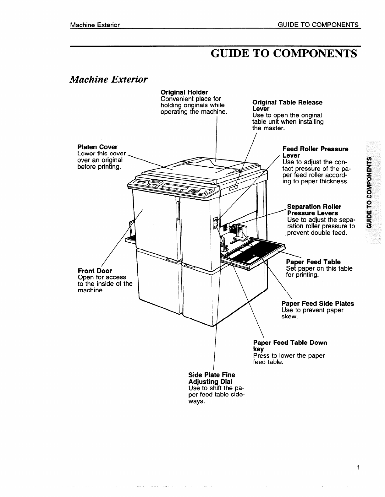
Machine Exterior
Machine Exterior
GUIDE TO COMPONENTS
Original Holder
Convenient place for
holding originals
operating the machine.
while
I
GUIDE TO COMPONENTS
Original Table Release
Lever
Use to open the original
table unit when installing
the master.
Platen Cover
Lower this cover
over an original
before printing.
Front Door
Open for access
too::i$eside of the
.
Feed Roller Pressure
Lever
Use to adjust the con-
/
tact pressure of the pa-
per feed roller according to paper thickness.
Separation Roller
= Pressure Levers
Use to adjust the separation roller pressure to
,prevent double feed.
r Feed Table
aper on this table
..
W \ !1 \ ‘orpr’nt’ng”
I
1
I
\
Paper Feed Side Plates
Use to prevent paper
skew.
/
Side Plate Fine
Adjusting Dial
Use to shift the paper feed table sideways.
Paper Feed Table Down
key
Press to lower the paper
feed table.
Page 7
GUIDE TO COMPONENTS Operation Panel
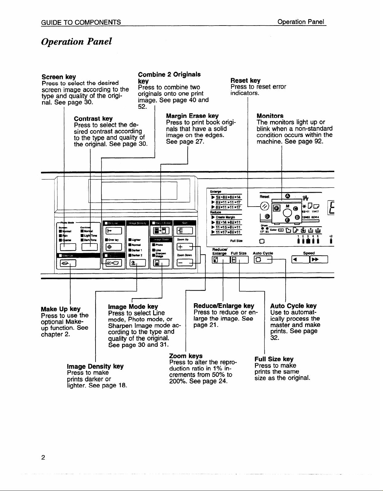
Operation Panel
Screen key
Press to select the desired
screen image according to the
type and quality of the origi-
nal. See page 30.
Contrast key
Press to select the desired contrast according
to the type and quality of
the original. See page 30.
Combine 2 Originals
key
Press to combine two
originals onto one print
image. See page
co
ad.
Margin Erase key
Press to print book originals that have a solid
image on the edges.
See page 27.
40 and
Reset key
Press to reset error
indicators.
Enhrge
wx8xmAJd4
p
p 8XXll ➤11 x~
➤ 84Jfll ➤11 X17
Reduce
➤ Create M8rgln
➤ 8XX14 ➤8XX11
P 11 X15*%X11
➤ 11 X17 MMX11
Full Slzo
Monitors
The monitors light up or
blink when a non-standard
condition occurs within the
machine. See page 92.
E
+2
i
I
I
Make Up key
Press to use the
optional Makeup function. See
chapter 2.
Image Density key
Press to make
prints darker or
lighter. See page 18.
I
I
r
Image Mode key
Press to select Line
mode, Photo mode, or
Sharpen Image mode according to the type and
aualitv of the original.
See page 30 and 31.
I
w
I
I
Zoom keys
Press to alter the reproduction ratio in 1940increments from
200?40.See page 24.
I
Reduce/Enlarge key
Press to reduce or enlarge the image. See
page 21.
50’%0to
El
1
Auto Cycle key
Use to automatically process the
master and make
prints. See page
32.
Size key
Full
Press to make
prints the same
size as the original.
db
Page 8
TROUBLESHOOTING
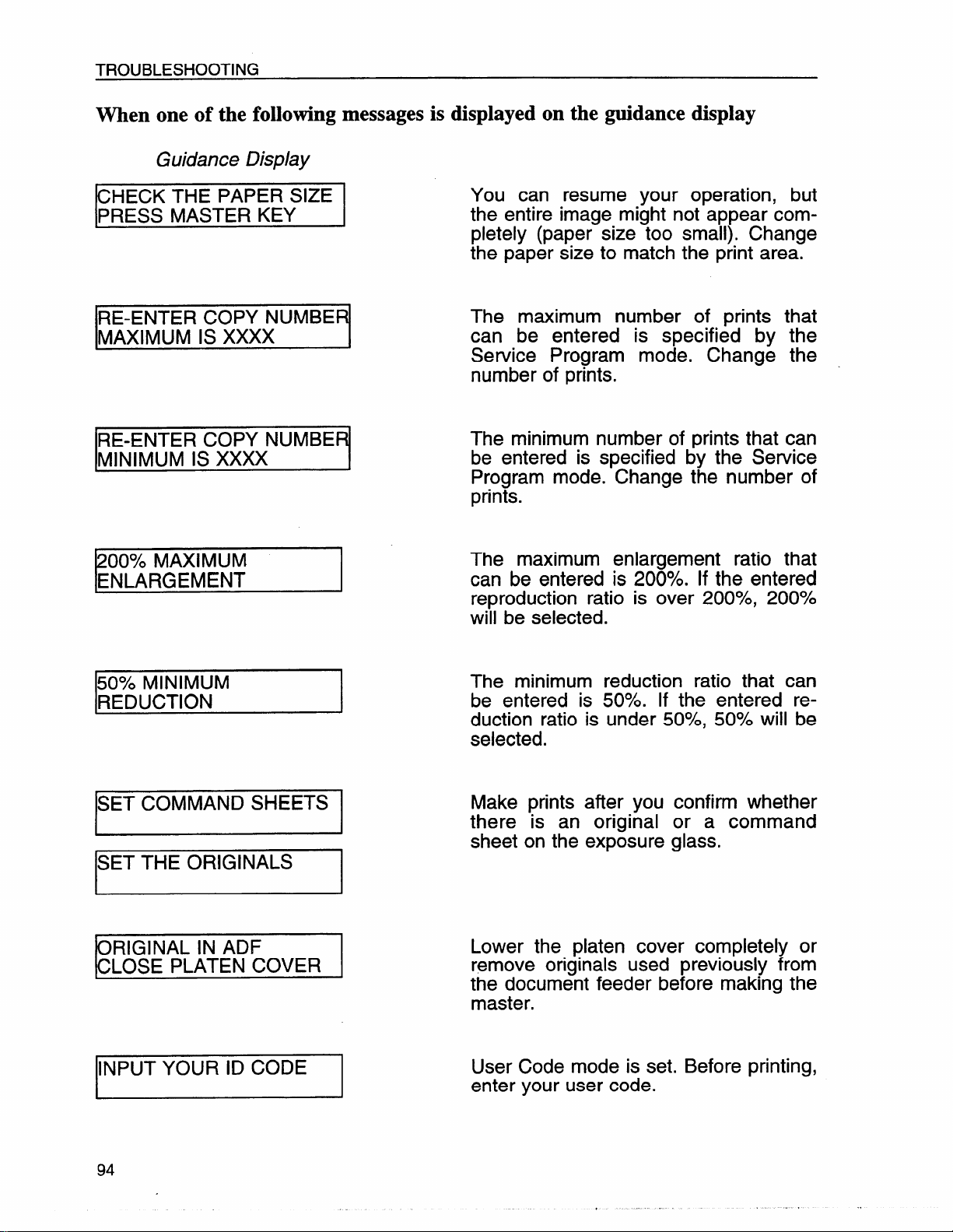
When one of the following messages is displayed on the guidance display
Guidance Display
CHECK THE PAPER SIZE
PRESS MASTER KEY
RE-ENTER COPY NUMBER
MAXIMUM IS XXXX
IRE-ENTER
lMINIMUM IS xxxx
200% MAXIMUM
ENLARGEMENT
cow NumERl
You can resume your operation, but
the entire image might not appear completely (paper size too small). Change
the paper size to match the print area.
The maximum number of prints that
can be entered is specified by the
Service Program mode. Change the
number of prints.
The minimum number of prints that can
I
be entered is specified by the Service
Program mode. Change the number of
prints.
The maximum enlargement ratio that
can be entered is 200940. If the entered
reproduction ratio is over 200?4, 200%
will be selected.
50?40 MINIMUM
REDUCTION
ISET COMMAND SHEETS I
SET THE ORIGINALS
ORIGINAL IN ADF
CLOSE PLATEN COVER
INPUT YOUR ID CODE
I
The minimum reduction ratio that can
be entered is 50?40. If the entered reduction ratio is under 50?4, 50?40will be
selected.
Make prints after you confirm whether
there is an original or a command
sheet on the exposure glass.
Lower the platen cover completely or
remove originals used previously from
the document feeder before making the
master.
User Code mode is set. Before printing,
enter your user code.
94
Page 9
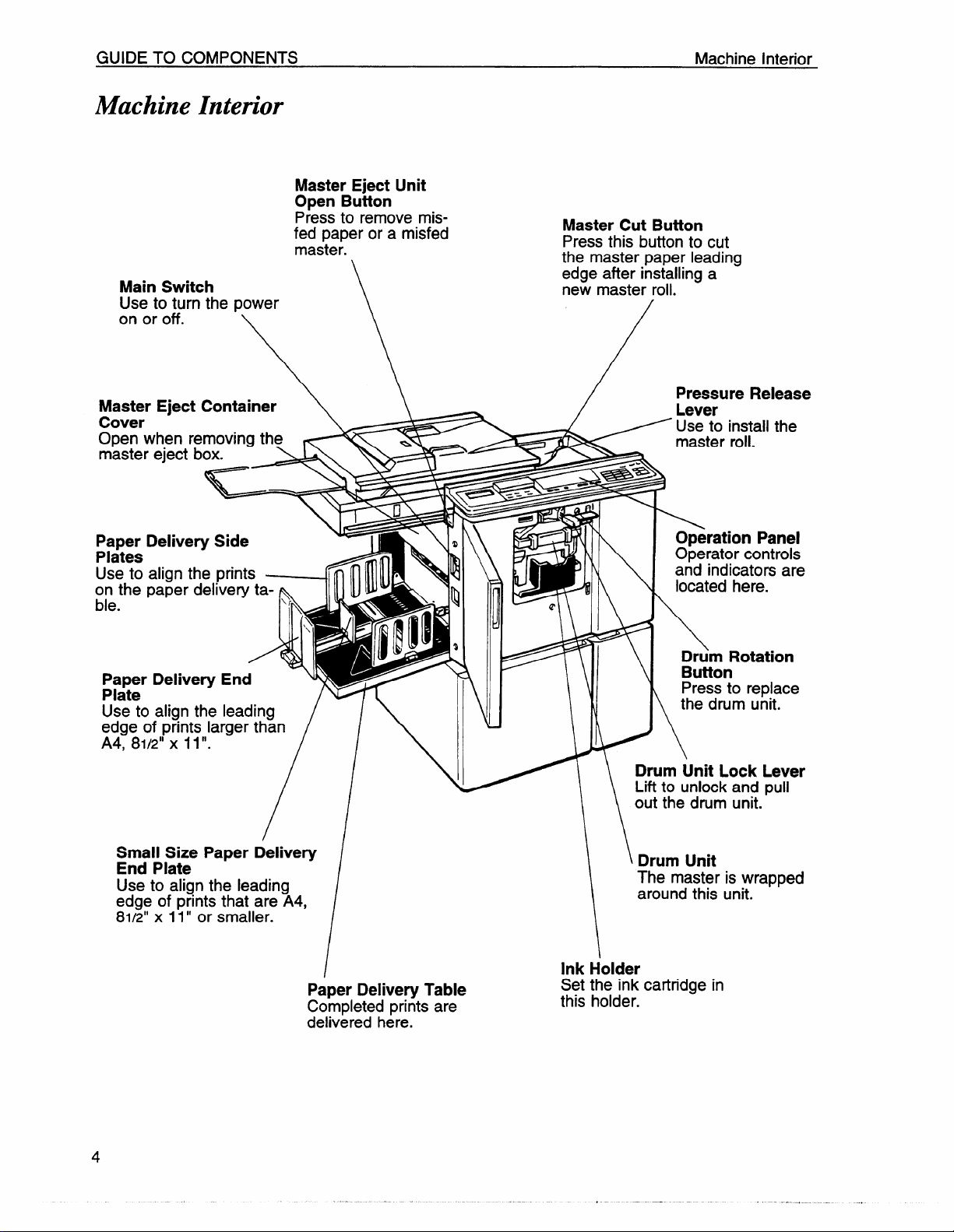
GUIDE TO COMPONENTS
Machine Interior
Main Switch
Use to turn the power
on or off.
Master Eject Unit
Open Button
P~essto remove misfed paper or a misfed
master.
\
Machine Interior
Master Cut Button
Press this button to cut
the master paper leading
edge after installing a
new master roil.
Master Eject Container
\\
Cover
Open when removing the
master eject box.
Paper Delivery Side
Plates
Use to align the prints
on the paper delivery ta-
ble.
Paper Delivery End
Plate
Use to align the leading
edge of prints larger than
A4, 81/2” x 11”.
Small Size Paper Delivery
End Plate
Use to align the leading
edge of prints that are A4,
81/2” x 11” or smaller.
*’
T&
\r
4
ll
//
70!
IN
/
m> q ‘$ ‘ \
‘
~\
/ ,njo,?,nzrapped
!JI”k‘N
Pressure Release
Lever
Use to install the
master roll.
Operation Panel
111’d’
Operator controls
and indicators are
located here.
\
Drum Rotation
Button
Press to replace
the drum unit.
Drum Unit Lock Lever
Lift to unlock and pull
out the drum unit.
Paper Delivery Table
Completed prints are
delivered here.
Set the ink cartridge in
this holder.
Page 10
INSTALLATION REQUIREMENTS
Power Connection
Power Connection
IJ Connect the power cord to an appropriate power source (as described inside
of the front cover).
n Make sure the plug is firmly inserted in the outlet.
CI
Avoid multiwiring.
~ Do
CI Make sure that the wall-outlet is near the machine and easily accessible,
not pinch the power cord.
Page 11
Printing Paper OPERATION
OPERATION
Printing Paper
fJ
The following types of print paper are not recommended for this machine.
●
Paper smaller than 90 mm x 148 mm, 3.6” x 5.9”
●
Paper larger than 325 mm x 447 mm, 12.7” x 17.5”
●
Paper heavier than 209.3 g/m2, 55.6 lb
●
Paper lighter than 47.1 g/m2, 12.5 lb
●
Roughly-cut paper
●
Paper of different thickness in the same stack
●
Buckled or curled paper
●
Short grain paper
●
Low stiffness paper
n Maximum print area is as follows:
.
290 x412 mm, 11.4” x 16.2” with A3 drum.
290 x 204 mm, 11.4” x 8.0” with optional A4 drum.
A3 (297 x 420 mm), 11” x 17“, originals or printing paper can be used,
but the maximum print area is 290 x412 mm, 11.4” x 16.2” at 23°C,
73°F/65YoRH. Select Reduction mode to print the entire image of an A3,
11” x 17“ original.
IJ Correct curls in the paper before setting it in the machine. When you cannot
correct the paper curl, stack the paper with the curl face down. Otherwise the
paper might wrap around the drum or stains might appear.
IJ Store paper where it will not curl or absorb moisture. Use paper soon after it
is unpacked.
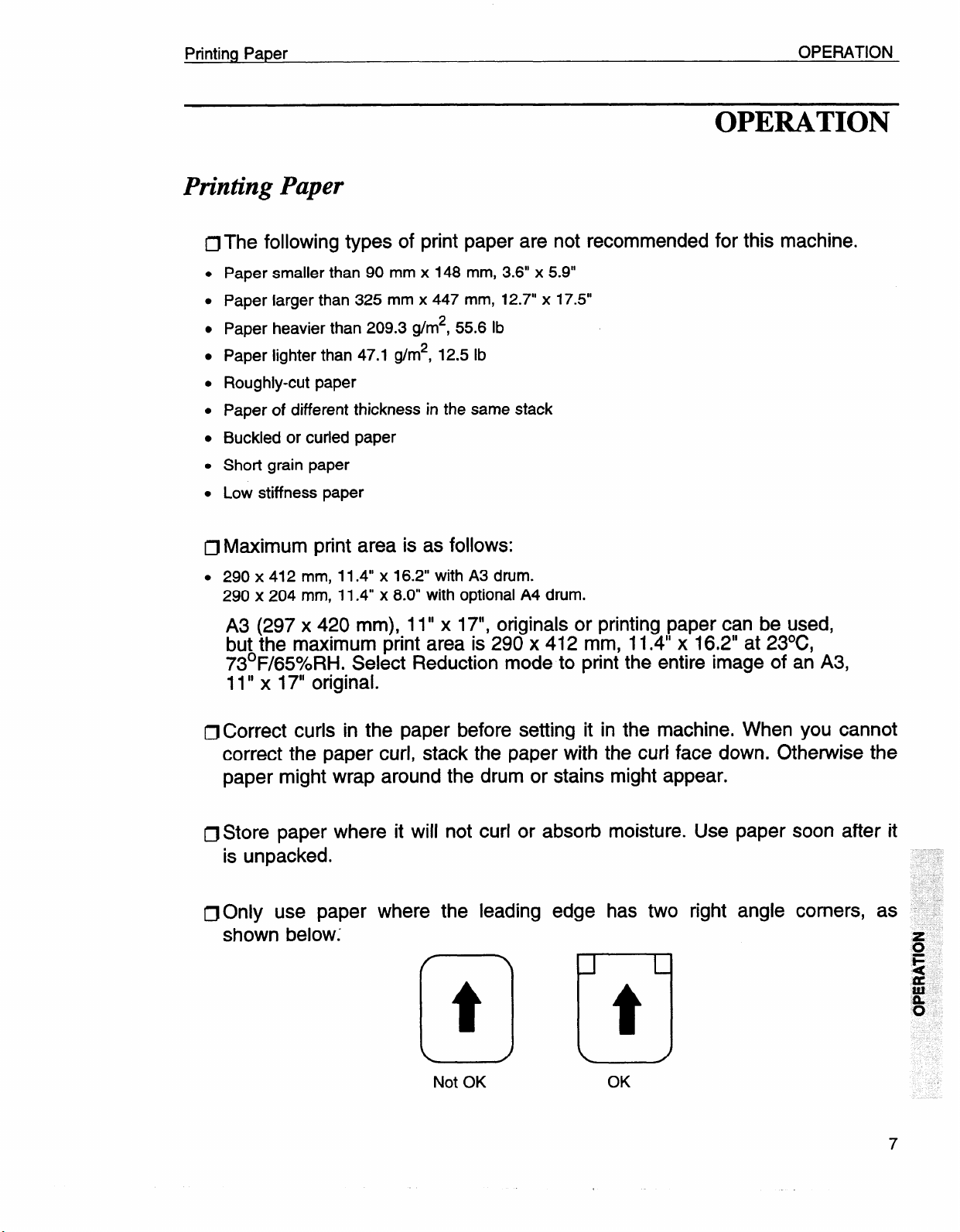
n Only use paper
shown below;
where the leading
edge has two
right angle comers,
Not OK
t
El
OK
Page 12
OPERATION
Originals
Originals
~
Under the following conditions, the machine might not detect the original on
the exposure glass. If you press the Master Making key again, the machine
will start making master anyway.
●
When you set a dark original on the exposure glass.
●
When the original is not centered according to the size marks on the left scale.
●
If you do not open the platen cover at an angle of more than 25 degrees with the exposure
glass when you replace originals.
The maximum original size you can set on the exposure glass is 307 x 432
n
mm, 12” x 17”.
~ If you use paste-up originals, make sure the pasted parts hold firmly to the
base sheet. If the thickness of the paste-up original is more than 0.2
2/250”,
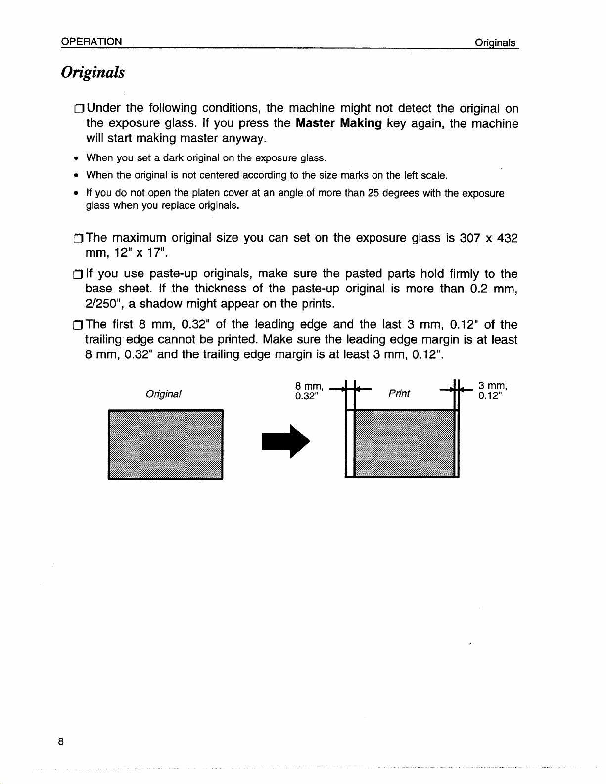
IJ The first 8 mm, 0.32” of the leading edge and the last 3 mm, 0.12“ of the
trailing edge cannot be printed. Make sure the leading edge margin is
8 mm, 0.32” and the trailing edge margin is at least 3 mm, 0.1 2“.
a shadow might appear on the prints.
at least
mm,
Original
8 mm,
0.32”
*
Print
*
3 mm,
0.12”
Page 13
Preparation For Printing
Preparation For Printing
OPERATION
. See page 61 when you load paper in the
Loading paper
w
)
P~
:s .....
.. .
. .+
.:: .
. ..
..
m
-00
e
-- . *3
● B4
Q
D
optional
paper cassette.
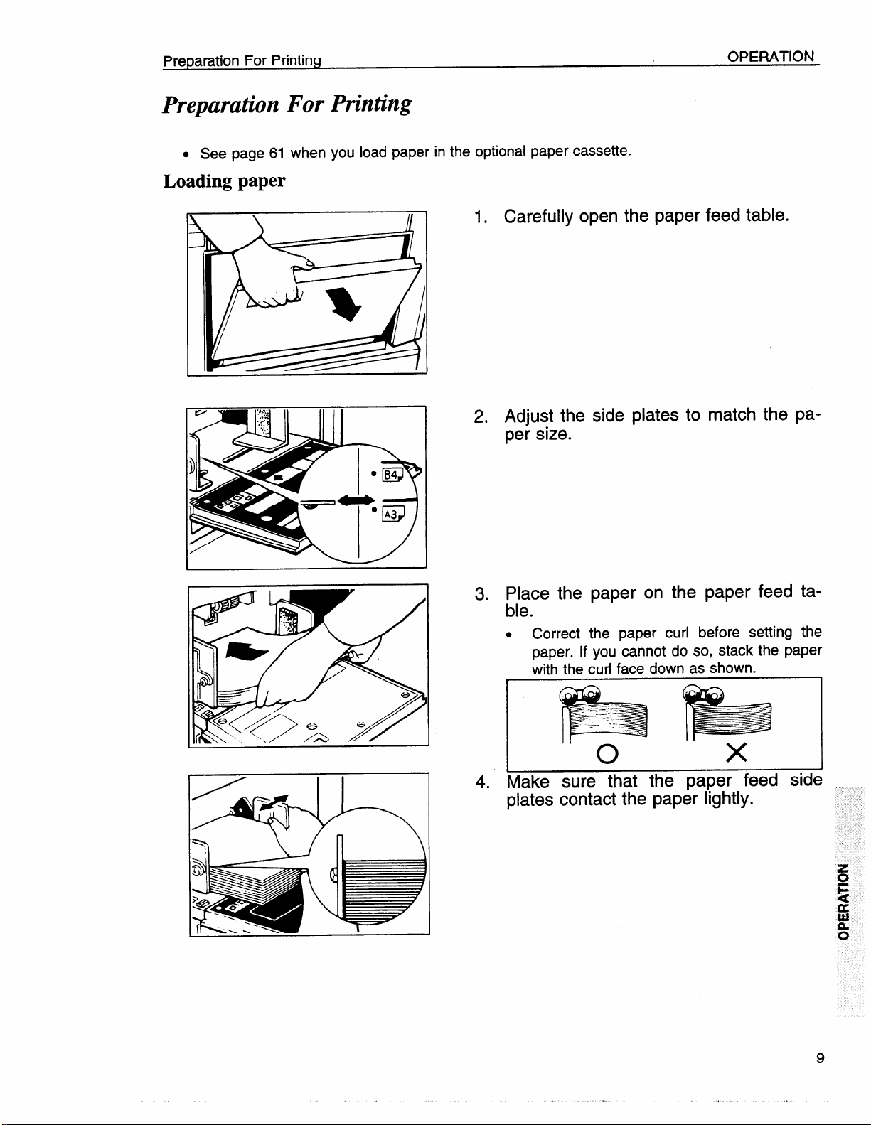
1. Carefully open the paper feed table.
2. Adjust the side plates to match the paper size.
3. Place the paper on the paper feed ta-
ble.
.
Correct the paper curl before setting the
paper. If you cannot do so, stack the paper
with the curl face down as shown.
&q
Make sure that the paper feed side
4.
plates contact the paper lightly.
z
u
F
4
&
a.
o
Page 14
OPERATION
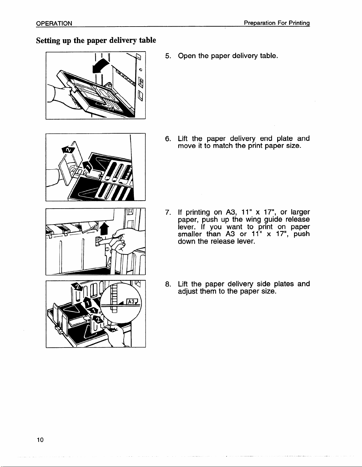
Setting up the paper delivery table
Preparation For Printing
5. Open the paper delivery table.
6. Lift the paper delivery end plate and
move it to match the print paper size.
I WI I
7. If printing on A3, 11” x 17“, or larger
paper, push up the wing guide release
lever. If you want to print on paper
smaller than A3 or 11” x 17“, push
down the release lever.
8. Lift the paper delivery side plates and
adjust them to the paper size.
Page 15
Preparation For Printing
OPERATION
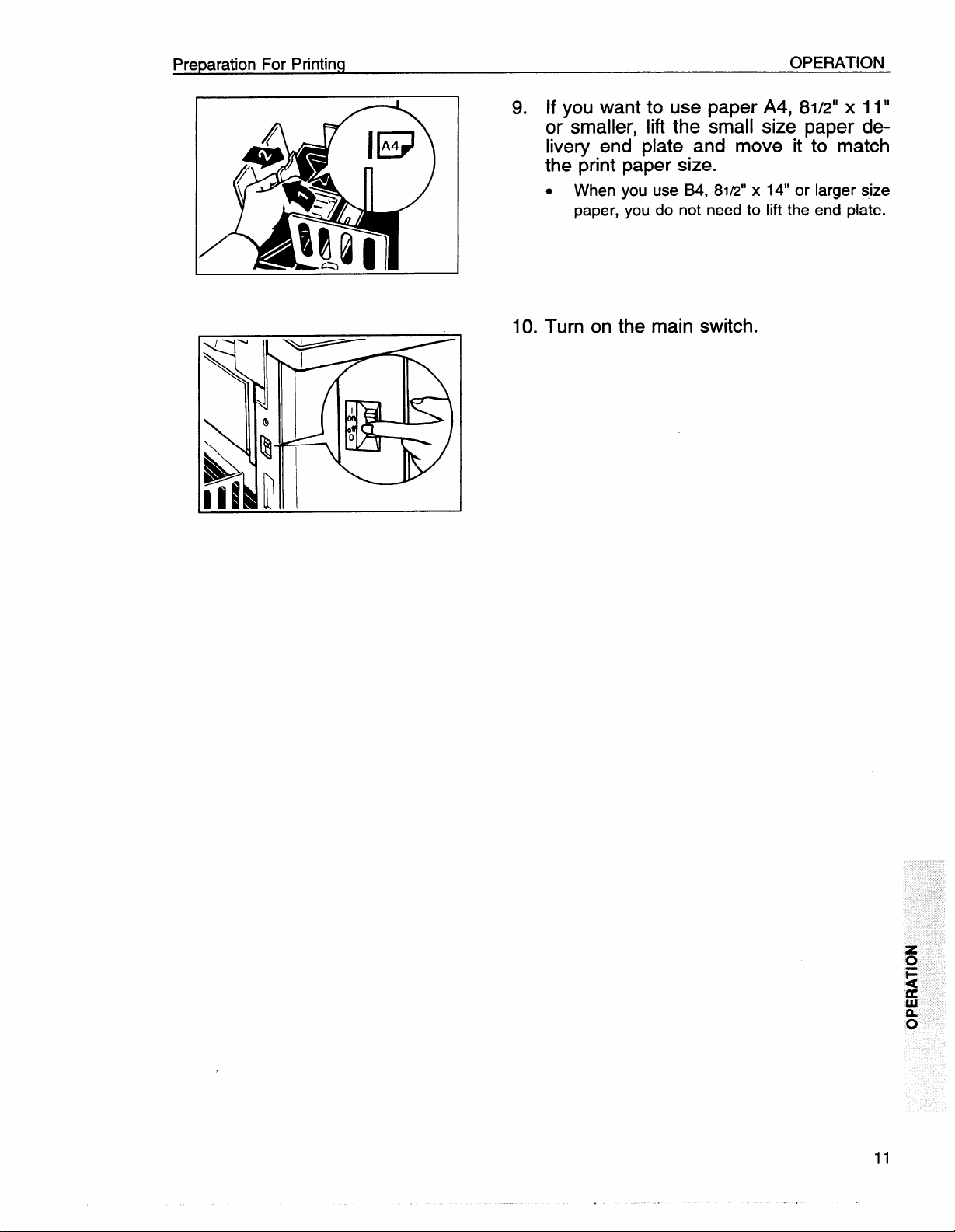
9. If you want to use paper A4, 8112”x 11”
or smaller, lift the small size paper de-
livery end plate and move it to match
the print
.
When
paper,
paper size.
you use B4, 8112”x 14“ or
you do not need to lift the
larger size
end plate.
10. Turn on the main switch.
Page 16
OPERATION
Standard Printing
Standard Printing
1
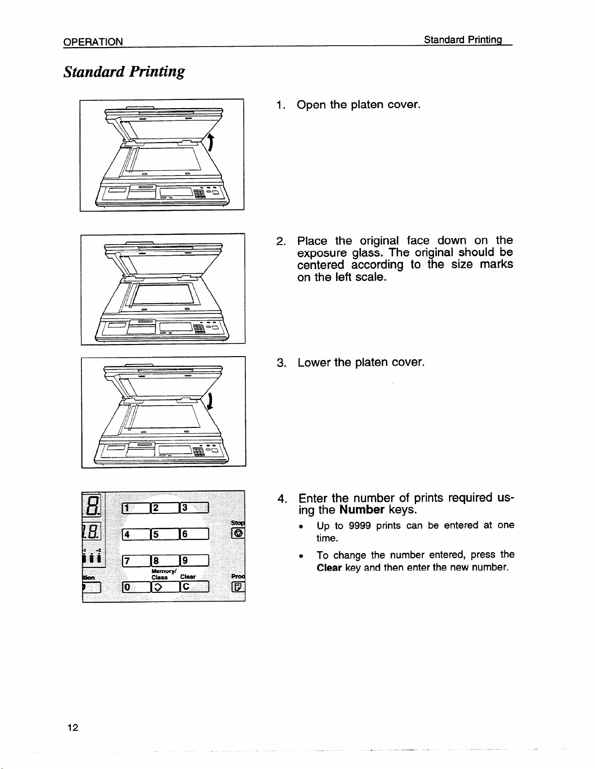
1. Open the platen cover.
2. Place the original face down on the
exposure
glass. The original should be
centered according to the size marks
on the left scale.
3.
Lower the platen cover.
4. Enter the number of prints required using the Number keys.
. Up to 9999 prints can be entered at one
time.
. To change the number entered, press the
Clear key and then enter the new number.
Page 17
Standard Printing
OPERATION
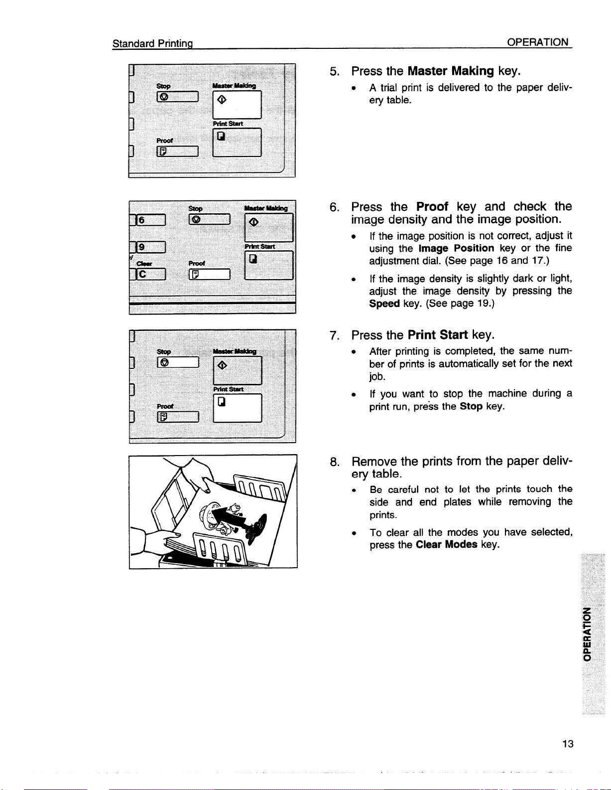
5. Press the Master Making key.
. A trial print is delivered to the paper deliv-
ery table.
6. Press the Proof key and check the
image density and the image position.
● Ifthe image position is not correct, adjust it
using the
adjustment dial. (See page 16 and 17.)
. If the image density is slightly dark or light,
adjust the image density by pressing the
Speed key. (See page 19.)
Image Position key or the fine
7. Press the Print Start key.
● After printing is completed, the same num-
ber of prints is automatically set for the next
job.
you want to stop the machine during a
. If
print run, press the
Stop key.
8. Remove the prints from the paper delivery table.
. Be careful not to let the prints touch the
side and end plates while removing the
prints.
. To clear all the modes you have selected,
press the
Clear Modes key.
13
,,
Page 18
OPERATION
Restoring Paper Feed And Paper Delivery Tables
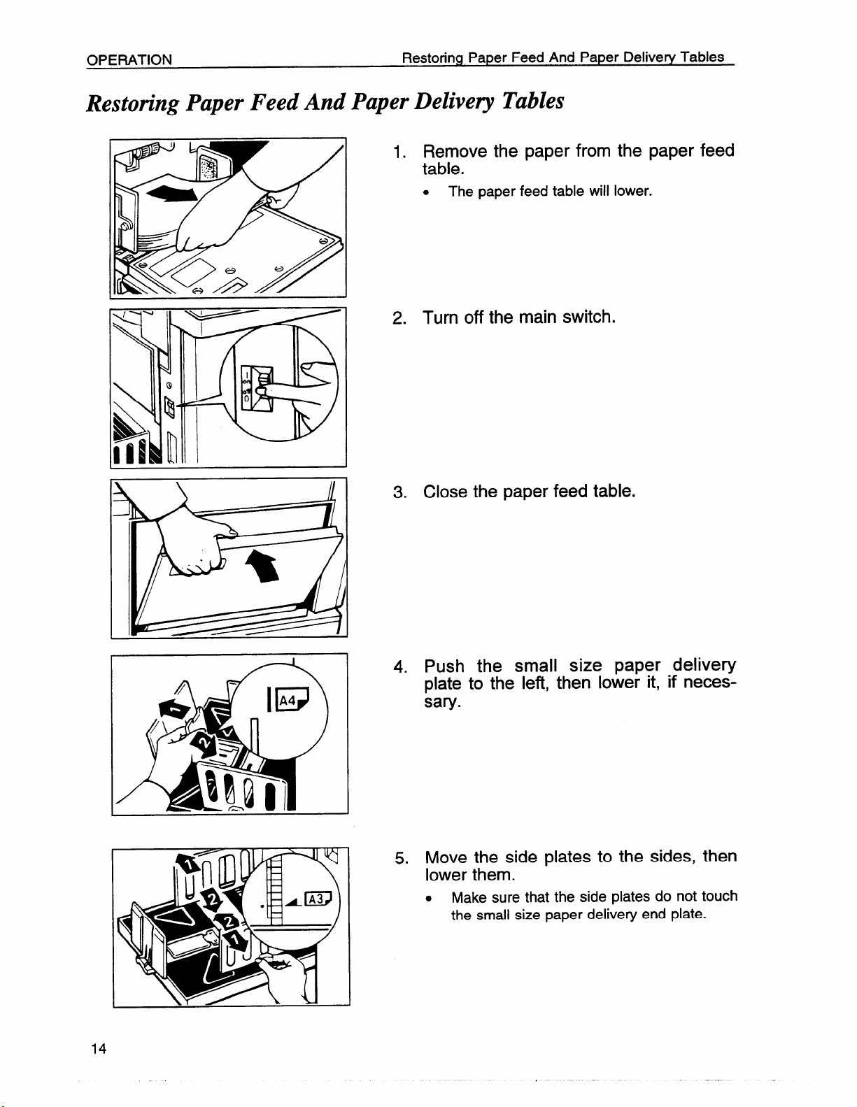
Restoring Paper Feed And Paper Delivery Tables
1. Remove the paper from the paper feed
table.
.
The paper feed table will lower.
2. Turn off the main switch.
3. Close the paper feed table.
4. Push the small size paper delivery
plate to the left, then lower it, if necessary.
5. Move the side plates to the sides, then
lower them.
.
Make sure that the side plates do not touch
the small size paper delivery end plate.
Page 19
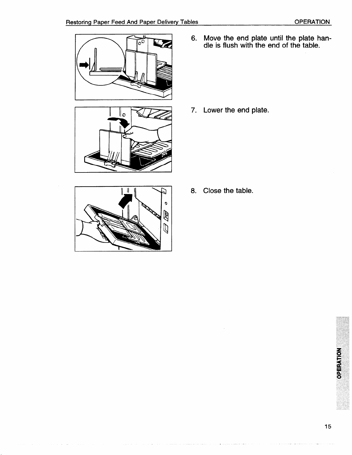
Restoring Paper Feed And Paper Delivery Tables
6. Move the end plate until the plate han-
I
7. Lower the end plate.
OPERATION
dle is flush with the end of the table.
8. Close the table.
Page 20
OPERATION
Adjusting The Image Position
A&usting
If the image
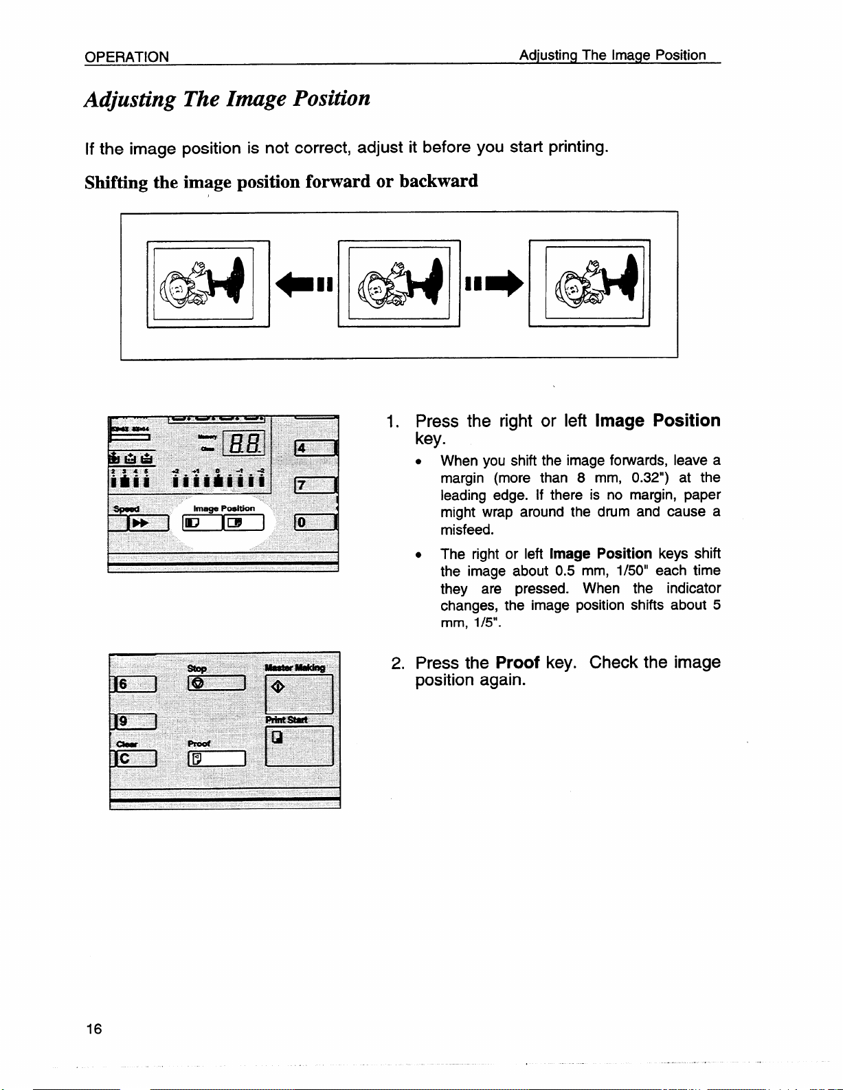
Shifting the
The Image Position
position is not correct, adjust it before you start printing.
image position forward or backward
1. Press the right or left Image Position
key.
. When you shift the image forwards, leave a
margin (more than 8 mm, 0.32”) at the
leading edge. If there is no margin, paper
might wrap around the drum and cause a
misfeed.
. The right or left
the image about 0.5 mm, 1/50” each time
they are pressed.
changes, the image position shifts about 5
mm, 1/5”.
Image Position keys shift
When the indicator
2. Press the Proof key. Check the image
position again.
Page 21
Adjusting The Image Position
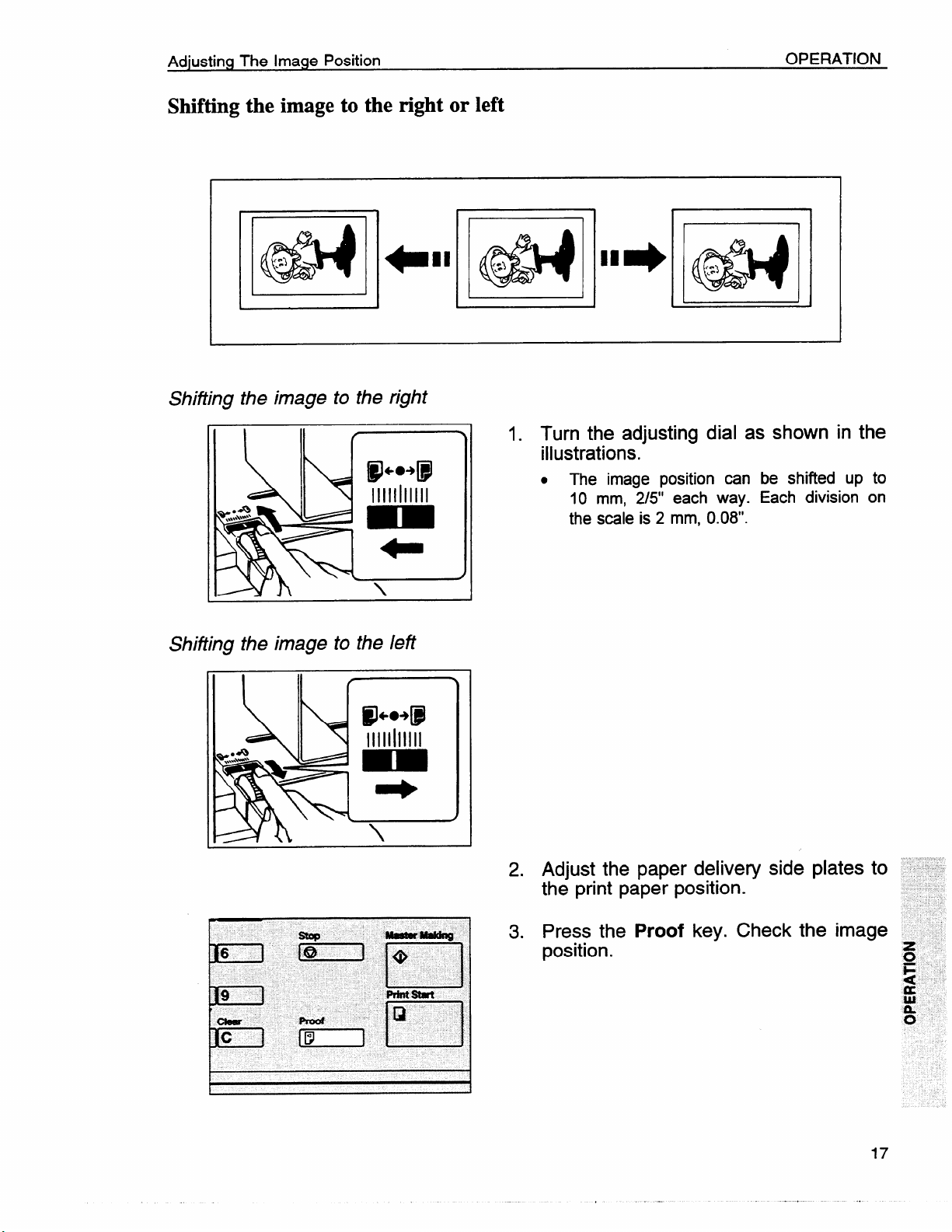
Shifting the image to the right or left
OPERATION
I
Shiiting the image to the right
@J+.+@
11111111111
L
Shifting the image to the left
IP-49
11111111111
d
1. Turn the adjusting dial as
illustrations.
. The image position can be shifted up to
10 mm, 2/5” each way. Each division on
the scale is 2 mm, 0.08”.
1
in the
Adjust the paper delivery side plates to
2.
the print paper position.
3.
Press the
Proof key. Check
position.
Page 22

OPERATION
Adjusting The Image Density
Before making a master
Adjusting The Image Density
B
ti
mvawe
13E2 ::R’, :s”
IziEEl [’1 gz’-l
iDDnl
u
■ LigMtn
gDarkw2
After making a master
Use the Image Density key before
pressing the
m
n
a=
Press the
Master Making key.
Speed keys. To increase the
speed, press the ‘*~” key. To reduce
the speed, press the “4” key.
. The faster the printing speed becomes, the
lighter the printing density is. If you want
darker prints, decrease the printing speed.
Page 23
Changing The Printing Speed
Changing The Printing Speed
OPERATION
Use the Speed keys
and printing paper.
to adjust the speed of the machine with the image density
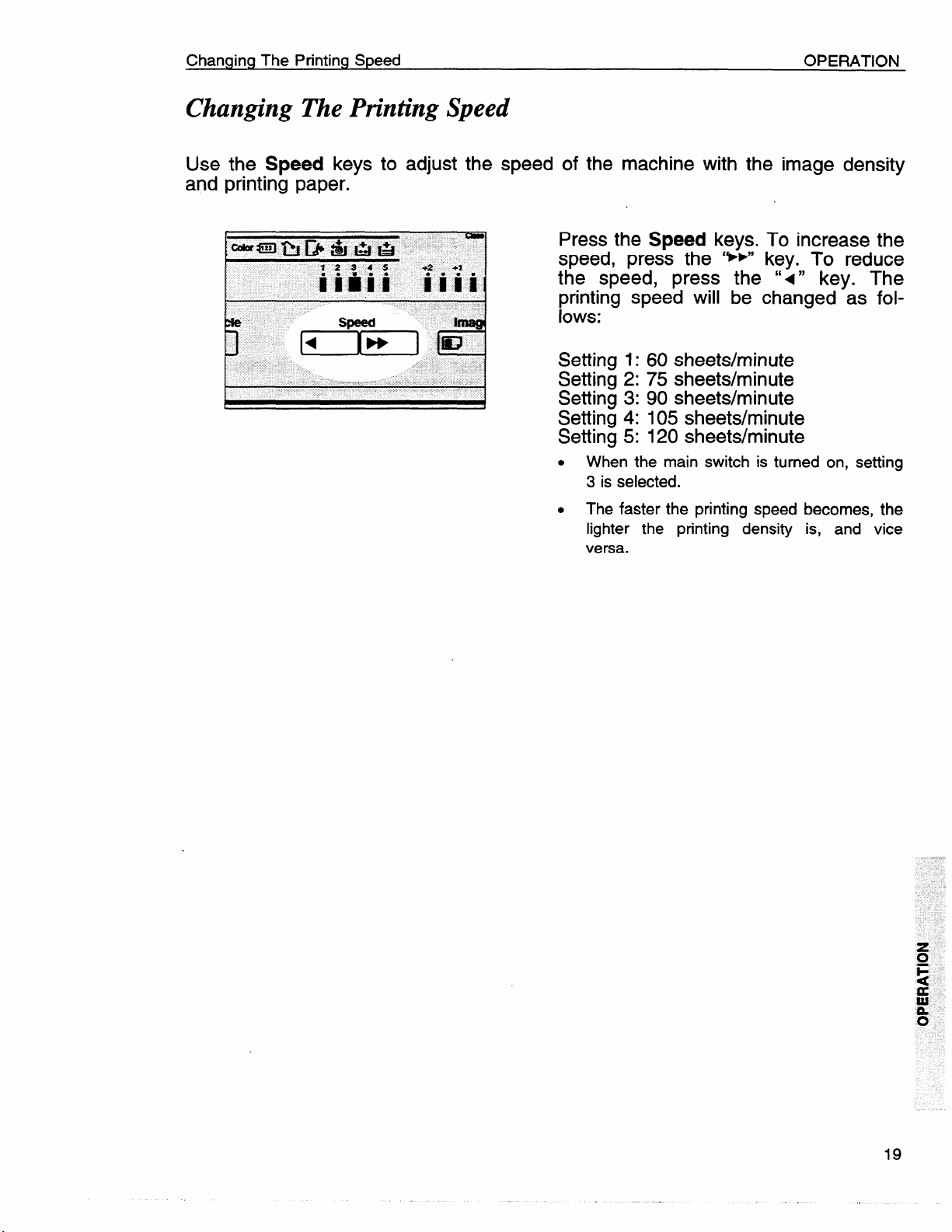
Press the
Speed keys. To increase the
speed, press the ‘**” key. To reduce
the speed, press the “<” key. The
printing speed will be changed as follows:
Setting 1:60 sheets/minute
Setting 2:75 sheets/minute
Setting 3:90 sheets/minute
Setting 4:105 sheets/minute
Setting 5:120 sheets/minute
. When the main switch is turned on, setting
3 is selected.
. The faster the printing speed
lighter the printing density
versa.
becomes, the
is, and vice
Page 24
OPERATION
Stopping The Machine During A Printing Run
Stopping The Machine During A Printing Run
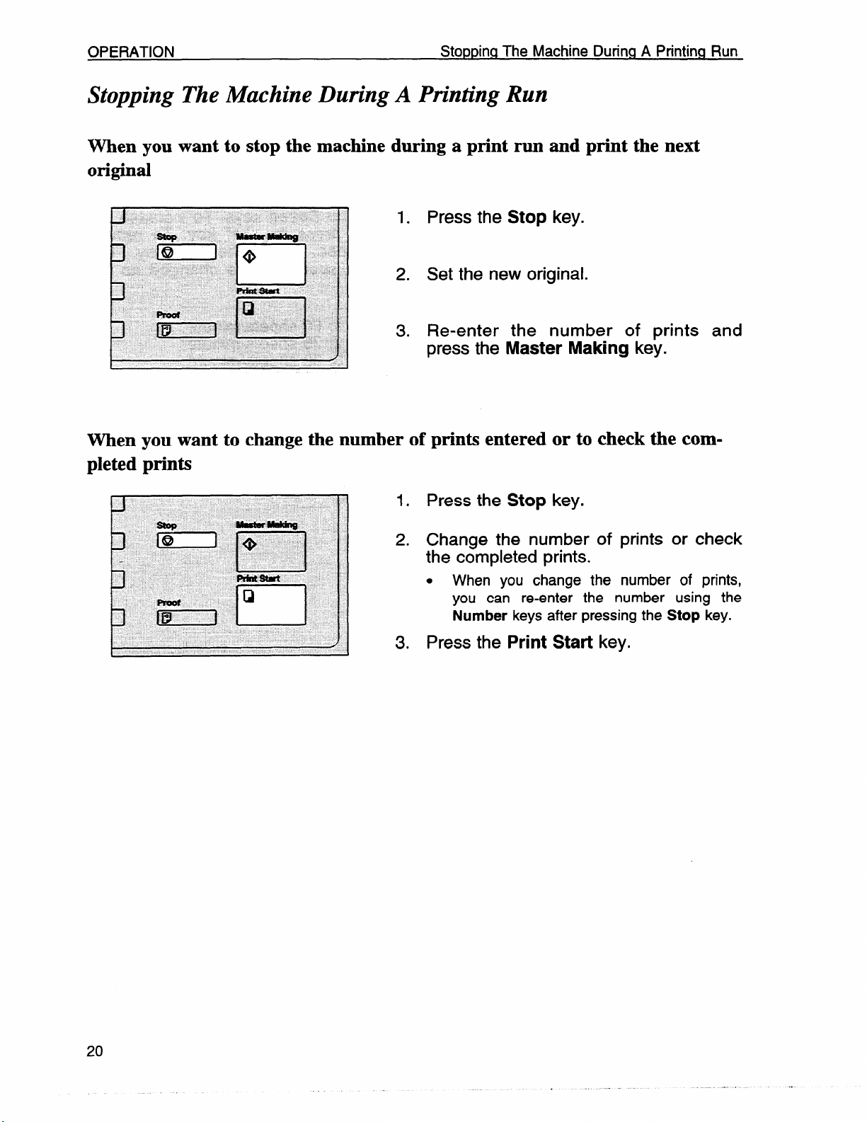
When you want to stop the machine during a print run and print the next
original
1. Press the Stop key.
2. Set the new original.
3. Re-enter
press the
the number of prints and
Master Making key.
When you want to change the number of prints entered or to check the completed prints
1. Press the Stop key.
2. Change the number
the completed prints.
.
When you change the number of prints,
you can re-enter the number using the
Number keys after pressing the Stop key.
Press the Print Start key.
3.
of prints or check
Page 25
Reduce/Enlarge Printing
Reduce/Enlarge Printing
OPERATION
● The
with
center and the
this function.
leading
edge of the print image do lot shift when a print image is made
Print
t
A
Full siz,
Ro8uctm
R
P8fmr
Feed
Chmction
0
-L
Consmnt
~
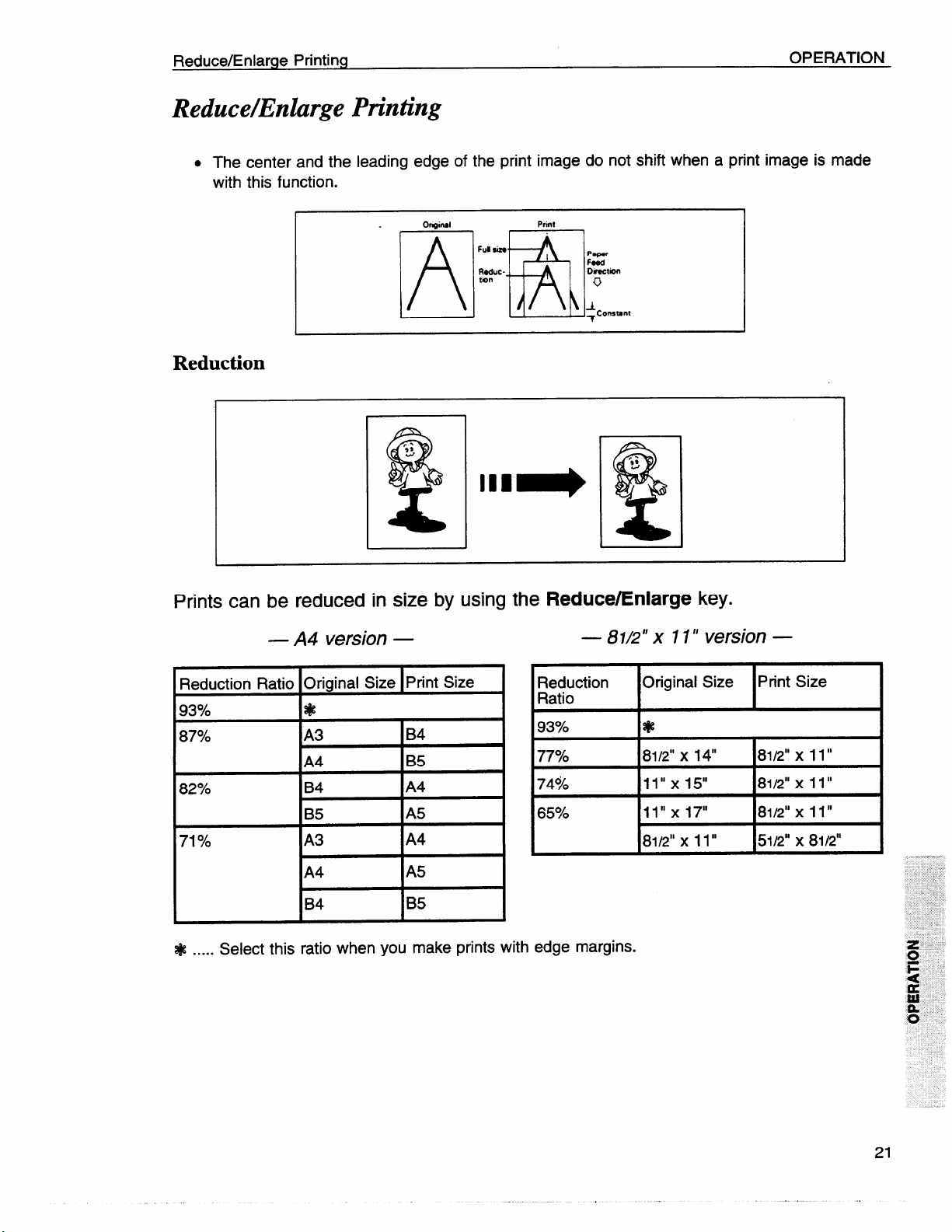
Reduction
Prints can be reduced in size by using the Reduce/Enlarge key.
— A4 version —
Reduction Ratio
93%
87940
I
i?--E--
82%
71%fO
Select this ratio when you make prints with edge margins.
.....
*
B4
A4
B4
IA4
A5
I
IB5
— 81/2” x 11” version —
Reduction Original Size
Ratio
93%
7770
7490 11’’ XI5° 8112”x 11”
65?40
*
X 14“
81/2”
11” x 17” 8112”x 11”
L
8112”x 11” 51/2” x 81/2t’
Print Size
81/2” X 11“
Page 26
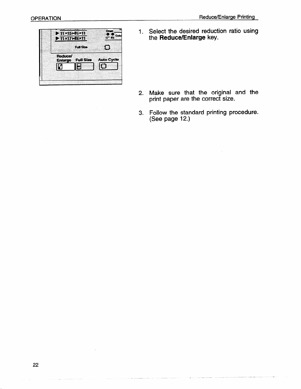
Reduce/Enlarge Printing
1. Select the desired reduction ratio using
the
Reduce/Enlarge key.
2. Make sure that the original and the
print paper are the correct size.
3. Follow the standard printing procedure.
(See page 12.)
Page 27
Reduce/Enlarge Printing
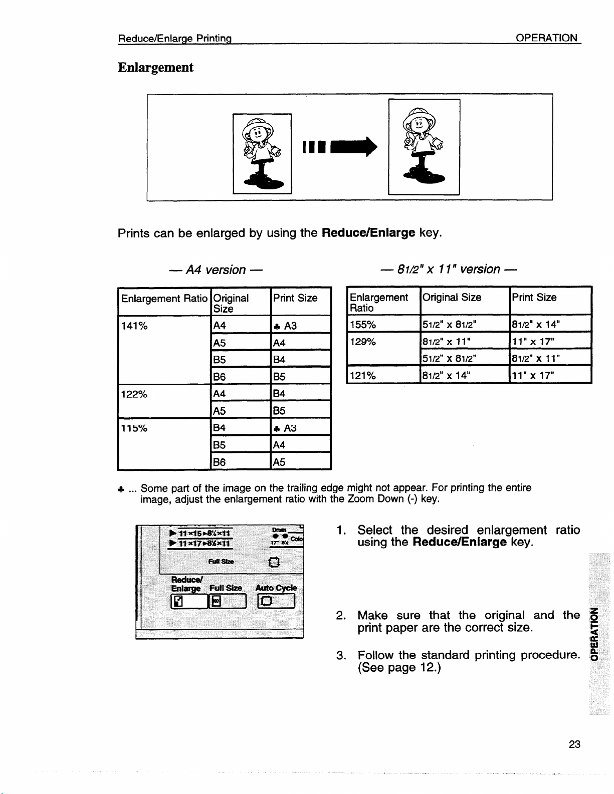
Enlargement
Prints can be enlarged by using the Reduce/Enlarge key.
OPERATION
— A4 version —
Enlargement Ratio O&inal
I
141Yo
122%-0
115?40
...
Some patt of the image on the trailing ed! Ie might not appear. For printing the entire
+
image, -adjust the enlargement ratio
IA4
tA5 1A4
B5
B6
A4
A5
IB4
IB5
IB6
Print Size
I
B4
B5
B4
B5
k A3
IA4
with 1
~a~igement Original Size
155?40 51/2” x 8112”
129% 81/2”
121?40 81/2” x 14“
]e Zoom Down (-) key.
— 81L?”x 11” version —
x 11” 11’’ XI7°
51/2” x 81/2”
1. Select the desired enlargement ratio
using the
ReduceEnlarge key.
Print Size
8112”x 14“
8112”x 11”
11’’ X17°
2. Make sure that the original and the S
print paper are the correct size.
3. Follow the standard printing procedure. ~
(See page 12.)
F
s
Page 28
OPERATION
Zoom
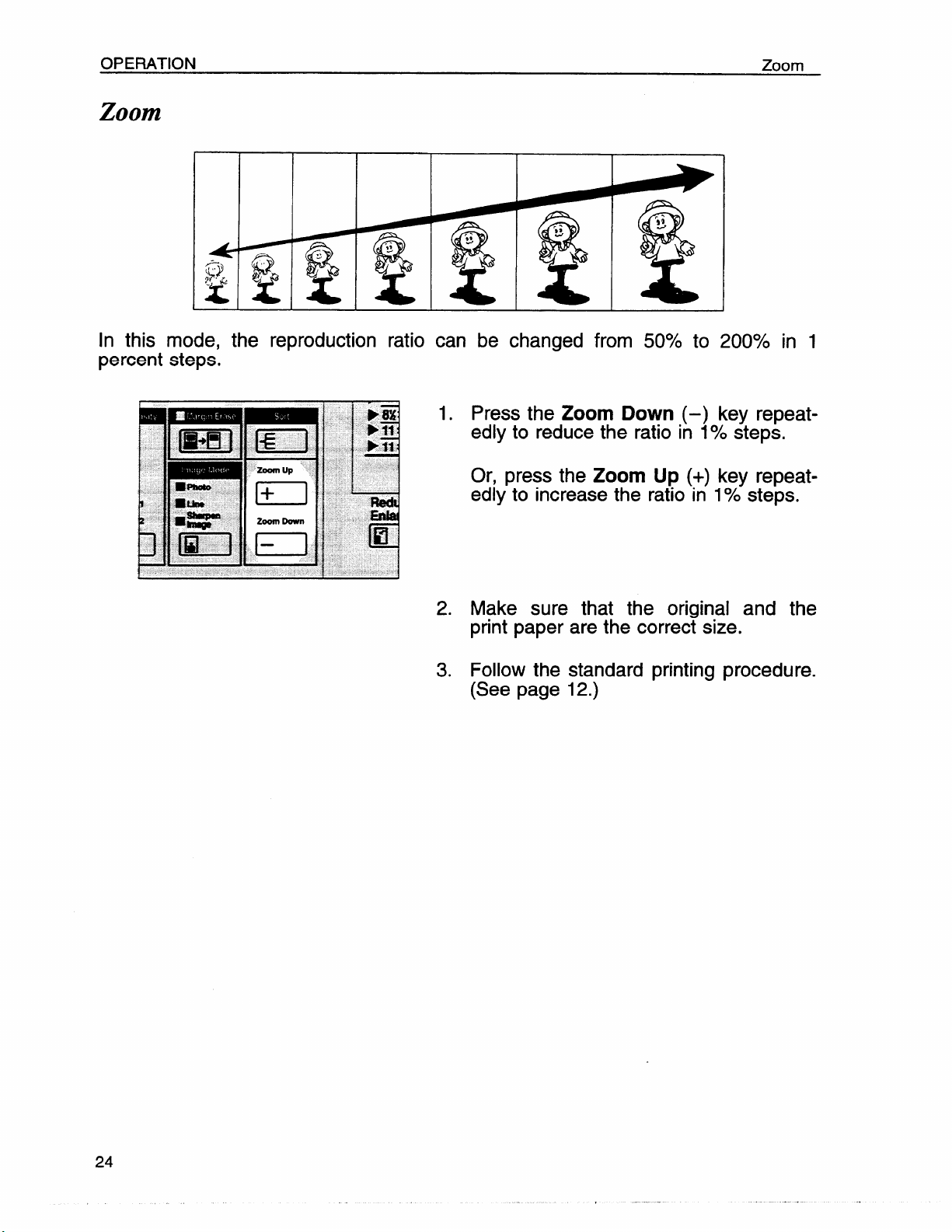
Zoom
In this mode, the reproduction ratio can be changed from 50% to 200’XO in 1
percent steps.
1. Press the Zoom Down
edly to reduce the ratio
Or, press the
edly to increase the ratio in
2.3.Make sure that the original and the
print paper are the correct size.
Follow the standard printing procedure.
(See page 12.)
Zoom Up (+)
(–) key repeat-
in 10/0steps.
key repeat-
1?40steps.
Page 29
Erasing Center And Edge Margins
OPERATION
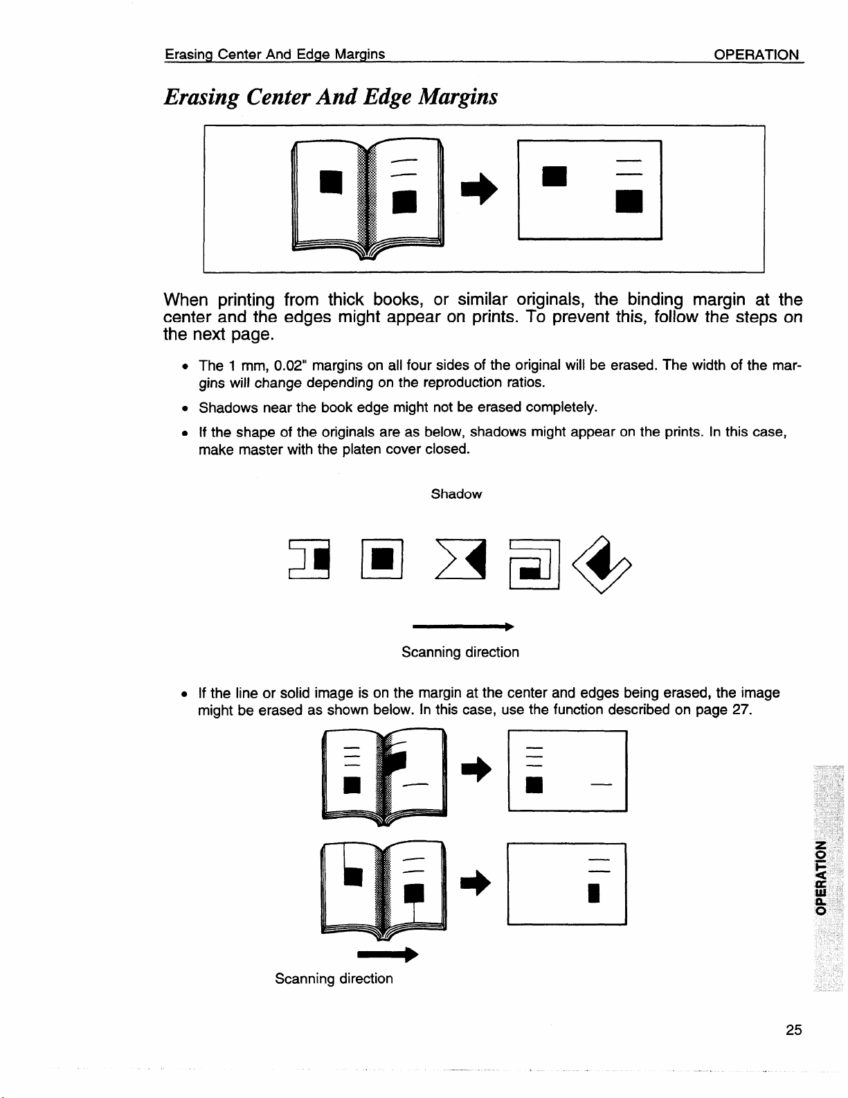
Erasing Center And Edge Margins
I
When printing from thick books, or similar originals, the binding margin at the
center and the edges might appear on prints. To prevent this, follow the steps on
the next page.
.
The 1 mm, 0.02” margins on all four sides of the original will be erased. The width of the margins will change depending on the reproduction ratios.
. Shadows near the book edge might not be erased completely.
. If the shape of the originals are as
make master with the platen cover
L
. If the line or solid image is on the margin at the center and edges being erased, the image
might be erased as shown below. In this case, use the function described on page 27.
1
J
below, shadows might appear on the prints. In this case,
closed.
Shadow
J
~F=l@
Scanning direction
t 1
b
—
El
Scanning direction
Page 30
OPERATION
●
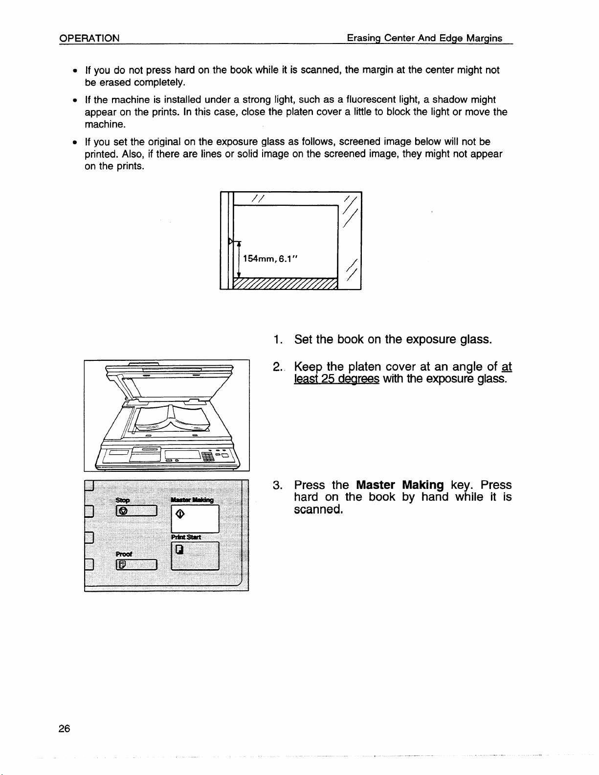
If you do not press hard on the book while it is scanned, the margin at the center might not
Erasing Center And Edge Margins
be erased completely.
●
If the machine is installed under a strong light, such as a fluorescent light, a shadow might
appear on the prints. In this case, close the platen cover a little to block the light or move the
machine.
●
If you set the original on the exposure glass as follows, screened image below will not be
printed. Also, if there are lines or solid image on the screened image, they might not appear
on the prints.
I
1.
Set the book on the exposure glass.
Keep the platen cover at an angle of ~
2.
least 25 dearees
Press the
3.
with the exposure glass.
Master Making key. Press
hard on the book by hand while it is
scanned,
Page 31

Erasing Center And Edge Margins
OPERATION
If you reproduce originals that have solid images at the edges, erasing the binding
and edge shadows will also erase solid images at the edge. To reproduce the
solid image, follow the steps below.
1. Set the original on the exposure glass.
4. The following message will appear on
the display. The paper size and direction will be changed by pressing the
Zoom key.
SCROLL BY ZOOM KEY
(YYY x XXXmm)
5. When you reach the desired paper size
and direction, press the
Then, make the master.
Enter key.
27
Page 32

OPERATION
Printing On Thick Or Thin Paper
Printing On Thick Or Thin Paper
When you make prints on
to 52.3 g/m2, 12.5 to 13.9
Printing on thick paper
thick (127.9 to 209.3 g/m2, 34.0 to 55.6 lb) or thin (47.1
lb) paper, do the following steps.
1. Push the pressure lever (A) down.
.
In the case of paper smaller than B5, 51/2”
x 81/2” and heavier than 127.9 g/m2 (34.0
lb), move the feed roller pressure lever to
the standard position.
2, Push the pressure levers (B) down.
.
There are two pressure levers (B). Make
sure that both levers are down.
● If dog-eared or wrinkled prints are deliv-
ered, push the levers up.
I VW
3. Pull the release lever up.
Page 33

Printing On Thick Or Thin Paper
Printing on thin paper
OPERATION
1. Set the side pads (move the side pad
levers to the right).
2. Pull the pressure lever (A) up.
I Ilfwl
3. Push the pressure levers
●
If dog-eared or wrinkled
ered, push the levers up.
. There are two pressure levers (B). Make
sure that both
4. Set the wing
match the print
levers are down.
guide release lever to
paper size.
(B) down.
prints are deiiv-
29
.,
Page 34

OPERATION
Photo Mode Printing
Photo Mode Printing
Original
Photo mode
Line mode
When printing a photograph or a color original, select Photo mode.
●
Moire patterns may occur when screened originals are printed.
●
When printing originals with letters and photos using Photo mode, the image of the letters
will be light. Select Line mode for letter areas and Photo mode for photo areas in the op-
1. Press the Image Mode key to select
Photo mode.
2. Press the
Image Density key to adjust
the image density.
3. Adjust the screen image by pressing
the
Screen key, if necessary.
Adjust the contrast by pressing the
Contrast key, if necessary.
4. Follow the standard printing procedure.
(See page 12.)
Page 35

Sharpen Image Mode Printing
OPERATION
Sharpen Image Mode Printing
When the original is mostly made up of bold lines and characters, this mode
keeps the image sharp.
Press the Image Mode key to select
1.
Sharpen Image mode.
111=11 I
Press the
2.
the image
3. Follow the standard printing procedure.
(See page 12.)
Image Density key to adjust
density.
31
Page 36

OPERATION
Printing From Several Originals At Once
Printing From Several Originals At Once
the Auto Cycle key to process masters and make prints at one stroke.
Use
●
When you use the optional document feeder, it is not necessary to place originals one by
one. AHoriginals are fed and prints are completed after you press the Master Making key.
●
If you use the optional tape dispenser, the tape dispenser drops a strip of paper onto the top
of the paper stack after the last page of each printing set is fed out to the paper delivery table. This marks the end of each printing group.
1. Set the original face down on the exposure glass.
.
You can set up to 20 originals into the optional document feeder.
2. Enter the number of prints required using the
3. Press the
Number keys.
Master Making key. Check
the image position on the trial print.
4. Press the Auto Cycle key.
s
The Auto Cycle indicator will light.
●
If you press the Auto Cycle key, you cannot make trial prints by pressing the Proof
key.
Page 37

Printing From Several Originals At Once
OPERATION
f%?’
5. If you use the optional tape dispenser,
turn on the power switch of the tape
dispenser.
Press the
6.
. If you set originals into the document
feeder, originals are fed and prints are
completed automatically.
7. Repeat steps 1 to 3 until all originals
are printed.
. After the last page of each set is fed out to
the paper delivery table, the optional tape
dispenser drops a strip of paper on the top
of the paper stack. The next cycle begins.
Print Start key.
33
Page 38

OPERATION
Group Printing From The Same Original (Class Mode)
Group Printing From The Same Original (Class Mode)
Use the Memory/Class key to make sets of prints from the same original. The
same number of prints is made for each set.
●
The optional tape dispenser automatically feeds out strips
ing groups on the paper delivery table.
●
Up to 20 sets of prints can be selected for one original.
1. Press the Memory/Class key to light
the Class indicator.
2. Set the original face down on the exposure glass.
of paper which
separate the print-
3. With the
Number keys, enter the num-
ber of prints for each set to be made
from the original.
Page 39

Group Printing From The Same Original (Class Mode)
4. Press the Enter key.
OPERATION
5. With the
Number keys, enter the de-
sired number of sets.
. The maximum number of sets that can be
made is 20.
6. Turn on the power switch of the optional tape dispenser.
7. Press the
Master Making key. Check
the image position by making prints
with the
. If the image position is not correct, adjust it
Proof key.
using the image Position key (See page
16) or the side plate fine adjusting dial.
(See page 17.)
35
.,
Page 40

OPERATION
Group Printing From The Same Original (Class Mode)
Press the Print Start key.
8.
. After the last page of each printing set is
fed out to the paper delivery table, the tape
dispenser drops a strip of paper on the top
of the paper stack.
●
If the power switch of the optional tape dispenser is turned off or the tape dispenser is
not installed in your machine, the group
printing cycle stops after each set is delivered. Remove the set of prints from the paper delivery table and press the Print Start
key to start the next group printing cycle.
Page 41

Group Printing From Different Originals (Memory Mode)
OPERATION
Group Printing From Dijjferent Originals (Memory Mode)
Use the Memory/Class key .to make sets of prints from different originals.
With the optional document feeder, you can set several originals and make prints of all of
them at once. For detail, see page 53.
The optional tape dispenser automatically feeds out strips of paper which separate the printing groups on the paper delivery table.
1. Press the Memory/Class key to light
the Memory indicator.
2. With the
Number keys, enter the de-
sired number of prints for the first origi-
nal.
3. Press the
Enter key. This stores the
number of prints to be made for the
first original in memory 1.
. When the number of prints in each set is
the same, it is not necessary to input the
number of prints for each group in memory.
Simply select the Auto Cycle mode and enter the desired number of prints once.
37
,,
Page 42

OPERATION Group Printing From Different Originals (Memory Mode)
4. With the Number keys, enter the num-
ber of prints for the second original.
5. Press the
number of prints
second original in
6. Repeat steps 4 and 5 for each
.
The number of prints can be
memory for 1 to 15 originals.
Enter
key. This stores the
to be made for the
memory 2.
original.
stored in
7. Press the Enter key again. The mem-
o~ returns to memory 1.
●
If you store the number of prints for 15
originals, the memory number returns to 1.
It is not necessary to press the Enter key.
8. Set the first original face down on the
exposure glass.
.
Set originals one sheet at a time in order
that you store in memory.
38
—a.
[
/
c
9. Press the
the image
(See page
Master Making key. Check
position on the trial prints.
12).
Page 43

Group Printing From Different Originals (Memory Mode)
10.
Turn on the power switch of the optional tape dispenser.
OPERATION
11.
Press the
c
If you press the Auto Cycle key, you cannot make trial prints by pressing the Proof
key.
Press the Print Start key.
12.
.
After the first set is fed to the paper deliv-
ery table, the tape dispenser drops a strip
of paper on the top of the paper stack.
After the first set is completed, set the
13.
Auto Cycle key.
second original on the exposure glass
and press the
Master Making key.
14.
Repeat step 13 until you have finished
printing.
.,
39
Page 44

OPERATION
Combine 2 Originals
Combine 2 Originals
You can print 2 separate originals on a single sheet of paper. The following tables
list the combinations that can be used when combining two originals.
A4 version —
Paper Size
Y
A3 lengthwise
B4 lengthwise
A4 lengthwise
B5 lengthwise
A5 lengthwise
— BI\z” x 11” version
Paper Size
11” x 17“ lengthwise
81/2”x 14“lengthwise
8112° x 11” lengthwise
51/2” x 81/2”lengthwise
A4
sideways
100?40 I 11570
87% I 1OOYO
71 ‘%0
6170 I 71%
50% I 57?40
Original Size 8112”x 11”
B5
sideways
I
I 82%
I 50?40 I 65%
A5
sideways sideways
B6
I
141% I 163?40
12270 1 14170
100%
sideways sideways
100?40 129?40
77?40
I 115%
5112”x 8112”
100?40
A6
sideways
200?40
173%
141%
122!!40
100?40
Page 45

Combine 2 Originals
OPERATION
D If the first original is wider than the maximum allowable width for combined
prints, the Combine 2 Originals mode will be canceled automatically after the
first original is on the master. The following table gives the maximum aHow-
able combined print width for each print paper size.
Maximum allowable original width for
combining
1210mm
I 182 mm
I 148 mm
I 105 mm
I 178 mm, 7.0”
140 mm, 5.5”
108 mm, 4.3”
prints
actual original width x magnification ratio
I
I
I
I
I
I
I
Maximum
Print paper size
A3
B4
A4 lengthwise
B5 Iermthwise I 128 mm
A5 Ienathwise
11’’XI7° I 216 mm, 8.5”
81I2”x 14”
81/2”x 11” length-
wise
51/2” x 81/2” length-
wise
allowable original width =
~Any image closer than 8 mm, 0.32” to the leading edge of the first original will
not be printed. Also, any image closer than 4 mm, 0.16” to the leading edge
of the second original will not be printed. When the image is too close to the
leading edge, use a copy of the original with the image shifted at least 8 mm,
0.32” for the first original (4 mm, 0.16” for the second original) from the leading edge.
~You can select a different kind of image settings for the first and second
original.
~ When you use the optional document feeder with this function, see page 52.
,,
41
Page 46

OPERATION
Combine 2 Originals
1. Set the
the top
first original face down and with
toward the operating side.
. The first original will be printed on the lead-
ing part of print.
,
2. Enter the number of prints using the
Number keys.
L
.“l
3. Check the print paper size and the reproduction ratio.
4.
Press the Combine 2 Originals key.
.
The Combine 2 Originals indicator will
light.
5. Press the Master Making key.
Page 47

Combine 2 Originals
OPERATION
6. The beeper sounds after the first oriainal is on the master. Set the
original face down and with
seco;d
the top
toward the operating side.
7. Press the
Making key.
8. Check the image position of trial prints
and press the
Print Start key.
43
.,
Page 48

OPERATION
User Program
User Program
This User Program function allows you to
job setups. -
How to input a user program
1.
2.
3.
store and recall
up to 5 frequently used
Select and enter the job settings you
want to store
Press the Program key.
.
Numbers already containing a program are
displayed on the guidance display.
in memory.
Enter “O”using the Number keys.
4.
Press the
●
The program numbers (1-5) will be dis-
played in the guidance display.
s
If a user program has been protected, that
program number will not appear in the display. For changing a protected user program, see page 46.
●
If all the user programs have been protected, the machine returns to the ready
condition.
Enter key.
Page 49

User Program
OPERATION
5. Enter one of the program numbers displayed on the guidance display using
the
Number keys.
. Make sure that the previous job setup
stored under the selected program number
are overwritten.
6. Press the Enter key.
45
Page 50

OPERATION
User Program
How to protect a program
If you want to prevent someone from writing over your program, do the following
procedure.
1. While pressing the
Reset key and Stop
key simultaneously, press the Program
key.
2. Enter “1” using the
3. Press the
●
The numbers of the programs which are
not protected will be displayed in the guidance display.
Enter key.
Number keys.
“,,”C-..?.—?.-?--”---- ,’——
.———-j
i
Iielm
4. using the Number keys, enter the
number of the program that you wish to
protect.
5. Press the
Enter key.
Page 51

User Program
How to remove user program protection
1. While pressing the Reset key and Stop
2.
OPERATION
key simultaneously, press the Program
key.
Enter “O”using the
Number keys.
3.
Press the Enter key.
●
If no program number is protected, the ma-
chine returns to the ready condition.
4.
Using the Number keys, enter the
number of the program that you
remove protection from.
5.
Press the
Enter key.
wish to
47
,!
Page 52

How to access a user program
User Program
1. Press the Program key.
.
Numbers already containing a program are
displayed on the guidance display.
2. Using the Number keys, enter the
number of the program that you wish to
access.
3. Press the
.
All stored job settings are recalled.
Enter key.
Page 53

Printing Using The Optional Document Feeder
OPTIONAL FUNCTIONS
OPTIONAL FUNCTIONS
Printing Using The Optional
Guide to document feeder component
ADF Unit Open Lever
Use to open the ADF unit.
Original Tray
Originals used to make
masters are delivered
the master “making =
position.
\ ‘hrna’scorrect’y”
#
e!!
Document Feeder
Original Guides
Adjus! these guides to position
I
I
I
I
49
.,
Page 54

OPTIONAL FUNCTIONS
Printing Using The Optional Document Feeder
Originals
D The following types of originals are not recommended for use with the docu-
ment feeder. Set the originals on the exposure glass.
●
Originals heavier than 127.9 g/m2, 34 lb
●
Originals lighter than 40.7 g/m2, 10.8 lb
●
Carbon coated originals
●
Damaged originals
●
Originals with glue on them
●
Originals with perforated for ring binders
●
Book originals
●
Originals written with a pencil or ball-point pen
●
Originals smaller than 90 mm x 140 mm, 3.6” x 5.6”
●
Originals larger than 307 mm x 432 mm, 12.0” x 17.0”
●
Folded, curled, creased originals
●
Bound, stapled, or clipped originals
n If you use paste-up originals, make
sure the pasted parts hold firmly to the
base sheet. If the thickness of the paste-up original is more than 0.2 mm,
1/1 25”, a shadow might appear on the prints.
~ The first 8 mm, 0.32”, of the leading edge and the last 2 mm, 0.08”, of the
trailing edge cannot be printed. Make sure the leading edge margin is at least
8 mm, 0.32”, and the trailing edge margin is at least 2 mm, 0.08”.
Original
8 mm, -
0.32”
Print
t- it-
2 mm,
0.08”
Page 55

Printing Using The Optional Document Feeder
OPTIONAL FUNCTIONS
Setting originals into the document feeder
.
If you set one original into the document feeder while another original is still on the exposure
glass, the original set into the document feeder will be scanned first.
1. Set the original tray.
2. Adjust the original
guides to the size of
the originals.
Insert the originals face down in the
3.
document feeder until it stops.
● Do not insert different size originals at the
same time.
. Approximately 20 originals can be inserted
at one time.
● The guides must fit snugly against both
sides of the stack.
4. Set the required image settings and
press the Master Making key.
●
If the next original has been set in the
document feeder before the machine stops,
that original is fed automatically and a trial
print is delivered to the paper delivery table
after the print of the first original is completed. Check the image position of the trial
print of the next original. (See page 16.)
51
,,
..
Page 56

OPTIONAL FUNCTIONS Printing Using The Optional Document Feeder
Combine 2 originals with the document feeder
.
Refer to page 40 for details about the Combine 2 originals funtion.
1. Insert the 2 originals face down and
with the top toward the operation side.
.
The first original fed will be printed on the
leading part of print.
2*
Enter the number of prints using the
Number keys.
3. Check the print paper size and the reproduction ratio.
4. Press the
5. Press the
.
After the first original is on the master, the
second original is fed.
. If you set only one original, the beeper
sounds after the first original is on the master. Set the second original and press the
Master Making key.
●
If you set only 2 originals, the Combine 2
Originals mode will be canceled after the
second original is on the master.
Combine 2 Originals key.
Master Making key.
Page 57

Printing Using The Optional Document Feeder
OPTIONAL FUNCTIONS
Group printing from different originals with the document feeder (Memory
mode)
.
To prevent original misfeed, do not set originals of different sizes.
. Do not set more than 15 originals at one time.
1. Follow steps 1 to 7 of page 37 and 38. *
2. Set the originals face down into the ~
document feeder.
● The originals are fed from the bottom of the
stack. Make sure that the originals are set
in the correct sequence with the first original on the bottom.
3. Press the Master Making key. Check
the image position on the trial prints.
(See page 16.)
m
z
o
i=
o
z
z
o
o
4. Turn on the power switch of the optional tape dispenser.
5. Press the
.
The Auto Cycle indicator will light.
. In Auto Cycle mode, printing starts auto-
matically after a trial print is delivered.
Auto Cycle key.
53
,,
Page 58

OPTIONAL FUNCTIONS
Printing Using The Optional Document Feeder
6. Press the Print Start key.
● After the last page of each set is
the paper delivery table, the tape
drops a strip of paper on the top
per stack. The next cycle begins.
fed out to
dispenser
of the pa-
Page 59

Color Printing Using The Optional Color Drum
OPTIONAL FUNCTIONS
Color Printing Using The Optional Color Drum
I
Color drum units (red, blue, green, and brown) are available as options in addition
to the standard black unit. For making color prints, a separate drum unit is
necessary for each color.
How to make color mints
*
Changing the drum unit for color
1. Make sure
lights.
2. Follow the
(See page
that the Color Print indicator
standard printing procedure.
12.)
printing
1. Open the front door.
NI& “1
2. Make sure that the lamp of the drum
rotation button is green. If this lamp is
red, press the drum rotation button until
the beeper sounds and the lamp turns
green.
55
Page 60

OPTIONAL FUNCTIONS
Color Printing Using The Optional Color Drum
3. Lift the lock lever until it locks in position.
4. Pull out the drum unit handle while
pressing the release bar inside the
green handle.
. If you cannot pull out the drum unit even
when the lamp of the drum rotation button
is green, push the drum unit handle, then
pull out the drum unit.
5. Hold the rail on the drum and slide out
the drum while pulling the release towards you.
6. Remove the drum unit from the machine while holding the upper drum
stay.
Caution: Be careful not to let the drum
unit fall.
Page 61

Color Printing Using The Optional Color Drum
OPTIONAL FUNCTIONS
7. Insert
guide
8. Slide
the color drum unit along the
rail.
in the drum unit until
unit locks in position.
9. Lower the drum unit lock lever.
the drum
10. Close the front door.
.
Make sure that the Cover Open indicator
turns off, and the Color Drum indicator
lights.
57
,,
Page 62

OPTIONAL FUNCTIONS
Color Printing Using The Optional Color Drum
Printing in two colors
After printing in one color, you can print in another color on the same side of the
print.
.
You cannot print in two colors at one time.
. Leave the printsfor a while before printing on them again. This lets the ink dry.
1. Prepare the two originals. Set the first
original on the exposure glass.
FI+H”+J
L
I 1 I I I
2. Enter the number of prints using the
Number keys.
3. Press the Master Making key.
● The original is fed, and the trial print is de-
livered to the paper delivery table. Check
image position. (See page 16.)
the
4. Press
the Print Start key.
5. Remove the prints from the paper delivery table and set them on the paper
feed table again as shown in the illustration.
Page 63

Color Printing Using The Optional Color Drum
OPTIONAL FUNCTIONS
6. Exchange the drum unit. (See page
---
7. Set the second original and press the
Master Making key. Check the image
position. (See page 16.)
8. Press the Print
Start key.
59
.
Page 64

OPTIONAL FUNCTIONS
Changing The Drum Size
Changing The Drum Size
To save costs on master rolls, you can shorten the length of each master by
changing to an optional smaller drum.
Printing area (at 23°C/730F, 65 % RH):
Max. 290 x 412 mm (1 1.4” x 16.2”) with A3 drum
Max. 290 x 204 mm (1 1.4” x 8.0”) with an optional A4 drum
Master cut length:
A3 drum
Optional A4 drum 11::
n To change the drum unit, follow the same procedure as “Changing the drum
unit for color printing”. (See page 55.)
320 mm x 540 mm, 12.5” x 21.2”, 225 masters/roll
320 mm x 332 mm, 12.5” x 13“, 370 masterslroll
Page 65

Printing Using The Optional Paper Cassette
OPTIONAL FUNCTIONS
Printing Using The Optional Paper Cassette
#The
If you always use 2 or more paper sizes, it is easy to change the paper size by ~
using the paper cassette. Set the paper you use most on the paper feed table and ~
set other paper in the cassette. You can use B4, A3,
paper in the A3 cassette, and B5, A4, or 81/2” x
Replenishing paper
The Load Paper indicator (l&J)lights when the paper cassette runs out of paper.
optional paper cassettes are not sold in some areas.
81/2”x 14“, or 11” x 17“ +
11” paper in the A4 cassette.
1. To remove the cassette cover, raise
both sections of the cover to the verti-
cal position, then pull the cover up and
out from its holders.
m
z
Q
z
o
&
~
2. Insert paper into the cassette,
care to align the sheets.
3. To replace the cover, fold both
sections toaether and insert the
as shown i;to the holders on the sides
of the cassette.
taking
cover
cover
61
Page 66

OPTIONAL FUNCTIONS
Printing Using The Optional Paper Cassette
4. Remove the paper from the paper feed
table.
.
The paper feed table will lower.
5. Adjust the feed roller pressure lever,
separation roller pressure levers and
wing guide release lever according to
the type of the paper. (See page 28.)
6. Adjust the side plates to the paper cassette size.
7. Using both hands, insert the cassette in
the machine and open the front section
of the cover, as shown.
8. Push the cassette forward until it stops.
Re-adjust the guide plates to the cas-
sette size.
●
If the side pads are positioned right, move
them to the left.
Page 67

Printing Using The Optional Paper Cassette
Removing the paper cassette
OPTIONAL FUNCTIONS
1. Press the Paper Feed Table Down ~
key. Pull out the cassette to the middle Q
of the paper feed
table and close the
cassette cover.
. To prevent paper
keep the cassette
ing the cassette.
from falling out, always
cover closed when mov-
63
Page 68

OPTIONAL FUNCTIONS Printing Using The Optional Paper Cassette
Changing the paper size
1. To remove the cassette cover, lift both
sections to the vertical position and pull
the cover up and out from its holders.
2. Turn the cassette upside down.
3. Loosen the 6 screws fixing the guide
plate at the right, left, and rear sides.
4. Slide the guide plates to the desired
position and tighten the screws.
Page 69

Printing Using The Optional Paper Cassette
A3 size paper cassette
OPTIONAL FUNCTIONS
5. Insert the sensor actuator in the slot
that corresponds to the cassette setting
(refer to the cassette size decal).
Examp/e: A3 printing
A4 size paper cassette
t
Example: A4 lengthwise printing
. If only one sensor actuator is required, be careful not to lose the other one.
65
Page 70

CHANGING DEFAULT SEVING,S
CHANGING DEFAULT SETTINGS
Printing needs may vary. To suit your application, you can adjust the setting for
certain functions. Functions that can be adjusted are as follows:
L
Minimum print quantity setting (SP # 10)
Specifies the minimum number of prints (O to 9999) that can be input with the
Number keys.
Example:
If
you specify 20 as the minimum number of prints,
runs of 20 or more copies will be accepted,
runs of less than 20 copies will not be accepted.
2.
Maximum print quantity setting (# 11)
Specifies the maximum number of prints (O to 9999) that can be input with the
Number keys.
3.
Fixed magnification ratio adjustment (#12 to # 19)
Adjusts any of the 8 fixed magnification ratios. The new fixed magnification
ratio is displayed on the guidance display by pressing the Reduce/Enlarge
key on the control panel.
4.
Beeper ON/OI?I?setting (# 20)
Turns the key beeper on or off.
5.
Optional key counter adjustment (# 21)
The key counter (option) usually counts the number of copies made regardless
of the number of masters used. For accounting purposes, it is possible for the
key counter to be incremented by a value between O and 50 whenever a new
master is used.
Example:
The key counter is adjusted to increase by 20 for each master fed. If 100
copies have
increase by 120.
been made and the master is replaced, the key counter will
Page 71

CHANGING DEFAULT SEITINGS
6.
Default mode selection
Specifies settings to which the machine defaults at power on. This can be done
for the following:
Image mode (3 possible settings) —
Image density level (4 possible settings)
Auto cycle mode (selects or deselects) —
Memory or Class mode (specifies one or the other) — #44
Make-up mode background pattern selection (# 46)
7.
This function can be used only when you have the optional Make-up function,
Specifies the default make-up mode background pattern that is selected
when the Make-up key is pressed.
8.
Skip paper feed setting (# 82)
If you find the back of prints are dirty, you can increase the time between
two prints. This gives you the chance to remove prints one by one from the
paper delivery table or insert one sheet of paper between two prints. With
the default setting, one sheet of paper is fed while the drum rotates once.
However, you can change the setting so that one sheet of paper is fed
each time the drum rotates two to five times. If you set the drum to rotate
two or five times each time one sheet of paper is fed, you can use 590 mm,
23.2”, or shorter paper.
The maximum length of paper is 447 mm, 17.5”. If you use paper longer than
447 mm, 17.5”, completed prints will not be delivered to the paper delivery
table properly, so receive them by hands.
#40
—# 41
# 43
9.
Auto Reset mode setting (# 83)
Sets the auto reset time (3 or 5 minutes). The machine automatically returns to
the default settings if no keys are pressed during this time period. This mode
can also be turned off.
10.
Auto combine 2 originals mode selection (# 84)
Select the Combine 2 originals mode as the default setting.
11.
Adding the master compression process at power on (# 85)
The master is always compressed after it is ejected into the master eject box, in
order to get a few more masters in the box. With this function, it takes 6 or 7
seconds for the machine to become ready when you turn on the main switch.
12.
Resettable total counter display/reset
Displays the total number of masters and copies —
Clears the resettable total counter —# 114
#113
67
Page 72

CHANGING DEFAULT SETTINGS
13.
Paper size detection selection (# 142)
The machine determines the print area size according to the reproduction ratio
and the size of paper set on the paper feed table. If you are making prints on
non-standard paper and the original image does not entirely appear on the
print, then set paper size detection not work. You can turn width or length
detection off separately.
14.
Original width detection selection (# 143)
The machine determines the print area size according to the size of the
original. If you are making prints using originals of a non-standard size and the
image does not entirely appear on the print, then set original detection not
work.
Erase margins adjustment area (# 160 to # 170)
15.
Margins erased by pressing the Margin Erase key can be adjusted.
Page 73

How To Access Setvice Programs
CHANGING DEFAULT
SET17NGS
How To Access Service Programs
The items described in the previous pages can be set by following this procedure.
1.
Press the keys on the operation panel
in the following order:
Clear Modes key
(1)
(2) Clear key
(3) Enter key.
● The sp-mode display appears on the guid-
ance display.
2.
Using the Number keys, enter the de-
sired sewice program number (listed
the service program table – see page
71).
in
When you leave the Service Program
3.
mode, press the Clear Modes key.
69
Page 74

CHANGING DEFAULT SEITINGS
How To Change Adjustment Values Or Modes
How To Change Adjustment Values Or Modes
1. After entering the desired setvice program number, press the Enter key.
The value or mode set at the factory
will be displayed at the end of the second line on the guidance display.
2. Enter the desired value or mode using
the Number keys.
3. Press the Enter key to store the desired value or mode.
4. When you leave the Setvice
mode, press the Clear Modes
Program
key.
Page 75

Service Program Table
Service Program Table
CHANGING DEFAULT SEITINGS
v: A4 version
SP No.
10.
11.
Minimum Print
Quantity
Maximum Print
Quantity
12.
13.
Fixed
Magnification
14.
‘
Ratio
Adjustment
15.
16.
17.
Mode
+; 8f~” x 11” version
Function
Sets the minimum print
quantity that can be
entered.
Sets the maximum print
quantity that can be
entered.
Adjusts a fixed
magnification ratio.
A4 version:
from A4 to A3
81n” x 11“
from
x 14“
Adjusts a fixed
magnification ratio.
A4 version:
from A4 to B4
84/2” x 11“ version:
from 8@’ x ll”to ll”X
17“
Adjusts a fixed
magnification
version:
A4
from B4 to A3
81/2” x 11” version:
from 81/2”x 14” to 11“ x
17“
Adjusts the full size
magnification ratio.
Adjusts the create
margin magnification
ratio.
Adjusts a fixed
magnification ratio.
version:
A4
from
81/2”x 11” version:
from 81/2”x 14” to 81/2”
x 11”
version:
51n” x 81/2”to 81/2”
ratio.
A3 to B4
Adjustment
Value
oto 9999
oto 9999
50 to 200%
50 to 200%
50 to 200%
50 to 200%
50 to 200!40
50 to 200%
0
9999
v: 141!40
+: 155%
v: 122’XO
●: 129%
v: 115?40
+: 121!40
100?40
93!!40
V: 87’XO
+: 77°h
Reference
Page 66-1
Page 66-2
Page 66-3
71
Page 76

CHANGING DEFAULT SEITINGS
Service Proaram Table
SP No.
18.
19.
20.
21.
40.
41.
43.
44.
46.
82.
83.
84.
85.
113.
Mode Function
Adjusts a fixed
magnification ratio. 4: 74?40
A4 version:
from B4 to A4
81/2” x 11” version:
Fixed
from 11“ x 15” to 81/2”x
Adjustment
Value
50 to 200%
Magnification 11”
Ratio
Adjustment
Beeper
Adjusts a fixed
magnification ratio.
A4 version:
from A3 to A4
81/2” x 11” version:
from 11“ x 17” to 81/2” x
,,,,
Turns the beeper ON or
OFF. 1: Yes
Prints/Master Adjusts the ratio of
cost
Image Mode
masters to prints for
accounting
purposes.
Specifies the image
Default Setting mode at power on.
50 to 200?40 v: 71°h
O:No
oto 50
O: Photo
1: Line
2: Sharpen
Image Density Specifies the image O:Light
Default Setting density at
Auto Cycle
Mode Default Cycle mode is selected 1: Yes
Memory/Class Specifies Memory or
Mode Default Class mode at power on.
Setting
Make-Up Specifies which make-up 1 to 40
Background background pattern is
Pattern Default selected when the Make-
Setting Up key is pressed.
Skip Feed Selects the feed interval. 1: Normal
Interval
Auto Reset
Time
Auto Combine Selects the auto
2 combine mode.
Adding the Sets the used masters to
master be compressed at power 1: Yes
compression on.
Resettable Used to display the total
Total Master/ number of masters and
Copy Counter copies. (This counter can
Specifies whether Auto
at power on.
Specifies the auto reset
time.
be reset.)
power on.
1: Standard
2: Dark
3: Darker
O:No
O: Class
1: Memory
51 to 90
101 to 140
150to 190
O: No back-
ground
pattern
1 sheet
fed every 1
t05 drum
rotations
O: No
1:3 min.
2:5 min.
O: No
1: Yes
O: No.
v: 82’!!40
+ : 65%
o
0
1
1
o
1
0
1
o
o
o
o
Page 66-3
Page 66-4
Page 66-5
Page 67-6
Page 67-6
Page 67-6
Page 67-6
Page 67-7
Page 67-8
Page 67-9
Page 67-10
Page 67-11
Page 67-12
Page 77

Service Program Table CHANGING DEFAULT SEITINGS
SP No. Mode
114.
120.
121.
122.
123.
124.
142.
143.
Clear
Resettable total masterlcopy counter.
Total
Master/Copy
Counter
User Code
Mode
User Code
Count
Clear User
Code Count
Total User Displays the total
Code Count
Clear Total
Code code counter.
User
Count
Paper Size Selects paper size O: Yes
Detection detection. 1: Width
Original Size Specifies whether O: No
Detection
Function
Clears the resettable
Selects user
Displays the number of
masters and copies
made in each
Clear each user code
counter. 1: Yes
number of masters and
copies
codes.
Clears the total user O: No
original size detection is
done.
code mode. O:No
user code.
for all the 20 user
Adjustment
Value
O:No
1: Yes
1: Yes
O:No
1: Yes
detection
2: Length
detection
3: No
detection
1: Yes
~e:
o
o
1
o
o
o
o
o
~eferen~e
Page 67-12
Page 75
Page 78
Page 79
Page 80
Page 81
Page 68-13
Page 68-14
73
.,
Page 78

CHANGING DEFAULT SETTINGS
Semite Program Table
SP
No.
160.
161.
162.
163.
164.
165.
166.
167.
168.
169.
170.
Mode Function Adjustment
Value
Erase
Margins
Adjustment
Area
Adjust the erase center
and edges area for an A3,
11” x 17“ oriqinal.
Adjust the erase center
and edges area for a B4,
81/2”x 14“ original.
Adjust the erase center
and edges area for an A4
lengthwise, 81/2” x 11”
lengthwise oriainal.
Adjust the erase center
and edges area for an A4,
81/2” x 11” original.
Adjust the erase center
and edges area for a 65
lengthwise, 51/2”x 81/2:’
Ienqthwise original.
Adjust the erase center
and edges area for a B5,
51/2” x 81/2” original.
Adjust the erase center
and edges area for an A5
lengthwise ori~inal.
Adjust{the erase center
and edges area for an A5
Driqinal.
Adjust the erase center
and edges area for an A6
Ienqthwise ori~inal.
Adjust the erase center
and edges area for an A6
ori~inal.
Adjust the erase center
and edges area for a
~maller than A6 original.
(50 -307
(50 -432
mm) x
mm)
Factorv
Settinti
v:289
+ :271
V :249 X 360
+ :208
V :202
+ :208
V:289 X 206
+ :271
v:174 X 253
+:132x212
v:249 X 178
+ :208 X 136
v:140 X 206
* :50 x 50
V:202 x 144
0:50 x 50
V:97 X144
$:50 x 50
V:140 x 101
0:50 x 50
v:92 X 144
0:50 x 50
X 416
X 428
X 352
X 293
X 275
X 212
Reference
Page 68-14
Page 79

User Code
CHANGING DEFAULT SEITINGS
User Code
With the user code function, operators must input an authorized code before the
machine will operate. The machine
under each code. In this
mode, the following 20 user codes (fixed) can be used to
keeps track of the number of prints made
access the machine:
382, 191, 182, 173, 164, 155, 146, 137, 128, 119,
482, 291, 282, 273, 264, 255, 246, 237, 228, 219
~ To prevent unauthorized users from accessing the machine, note down these
codes and then black out the codes from this manual.
How to enable user code mode (# 120)
The following procedure explains how to enable user code mode. This must be
done before a user code can be input.
1.
Press the keys in the following order:
(1) Clear Modes key
(2) Clear key
(3) Enter key.
Enter “120” using the Number
2.
and press the Enter key.
Enter “1” (Yes) using the Number keys
3.
and press the Enter key.
keys
75
Page 80

4. Specify the Auto Reset time.
Enter “1” (3 minutes) or “2” (5 minutes)
using the Number keys and
press the
Enter key.
5. Press the Clear Modes key to leave
SeNice Program mode.
76
Page 81

User Code
How to use user code mode
CHANGING DEFAULT SEITINGS
1. Input your assigned 3-digit user code
using the Number keys, then press the
Enter key.
2. Make your prints.
3. After you have finished, press the Stop
key while pressing the Clear Modes
key.
.
This prevents others from using your user
code to make prints.
● If you do not follow this step, the machine
will returns to the condition that you should
input your user code before making prints
after auto reset time.
77
.,
.,
Page 82

CHANGING DEFAULT SETTINGS
How to check the user code counter (# 121)
1. Press the keys in the following order:
(1)
(2) Clear key
(3) Enter key.
2. Enter “121” using the Number keys
and
The number of masters and prints
made under the
displayed in the guidance display.
User Code
Clear Modes key
press the Enter key.
user code “382” will be
3. Continue pressing the Enter key to display the number of masters and prints
made under your user codes.
4. Press the Clear Modes key to leave
Service Program
mode.
Page 83

User Code
How to clear the user code counter (# 122)
.
lfyouwant toclear every user code counter, seepage 81.
1.
2.
CHANGING DEFAULT SEl17NGS
Press the keys in the following order:
(1) Clear Modes key
(2) Clear key
(3) Enter key.
Enter “122”
using the Number
and press the Enter key.
keys
3. Keep pressing the Enter key until the %
desired user code is displayed.
4. Enter “1” using the Number keys and
press the Enter key.
5. Press the Clear Modes key to leave
Service Program mode.
g
s
o
79
Page 84

CHANGING DEFAULT SETTINGS
User Code
How to check the total number of masters and prints made under all user
codes (# 123)
1.
Press the keys in the following order:
(1) Clear Modes key
(2) Clear key
(3) Enter key.
2. Enter “123” using the Number keys
,
and press the Enter key.
● The total number of masters and prints
made under all user codes will be displayed
in the guidance display.
3. Press the Clear Modes key to leave
Service Program mode.
Page 85

User Code
How to clear the user code total counter (# 124)
1. Press the keys in the following order:
Clear Modes key
(1)
(2) Clear key
(3) Enter key.
2. Enter “124” using the Number keys
and
press the Enter key.
CHANGING DEFAULT SETHNGS
m
a
~
E
%
~
3
g
M
3. Enter “1” using the Number keys and ~
press the Enter key.
4. Press the Clear Modes key to leave
Service Program mode.
:
z
2
u
81
.
Page 86

REPLENISHING SUPPLIES
Loading Paper
On The Paper Feed Table
REPLENISHING SUPPLIES
Loading Paper On The Paper Feed Table
The Load Paper indicator (I&l) lights when the paper feed table runs out of paper.
1. Press the Stop key.
.
This step is necessary
pause a print run to replenish paper.
only if you want to
2. Press the Lower Paper Feed Table
key.
.
The paper feed table will lower without the
key being pressed when the printing paper
runs out.
. The top sheet might remain between the
feed rollers. In this case, remove the top
sheet.
3. Load paper on the paper feed table.
.
Release the pads of the feed side plates
before loading paper. Reset the pads after
paper is set.
. Correct the paper curl before setting the
paper.
4. Press the Print Start key to resume
printing.
82
Page 87

Loading Paper On The Paper Feed Table
Changing the paper size
REPLENISHING SUPPLIES
1. Remove the paper from the paper feed
table.
.
The paper feed tray will lower.
2. Adjust the paper feed side plates to
match the paper size.
3. Place the paper on the paper feed
ble.
.
Correct any paper curl before setting
paper.
. Make sure that the side plates contact
paper lightly.
4. Adjust the side plates
plate and if necessary,
and the end
the small size
end plate at paper delivery.
. Make sure that the wing guide release lever
positionscorrectly to match the paper size.
ta-
the
the
83
Page 88

REPLENISHING SUPPLIES Supplying Ink
Supplying Ink
The Add Ink indicator (@) lights when it is
1.
NF&”
2. Lower the ink holder and remove the
3. Remove the cap of the new ink car-
time to supply ink.
Open the front door.
used ink cartridge.
tridge.
4. Insert the new cartridge into the ink
holder. Return the ink holder to its original position until it clicks.
. Always supply ink of the same color.
Page 89

Supplying Ink
REPLENISHING SUPPLIES
5. Close the front door.
6. Press the Reset key.
.
The machine will start idling to supply ink to
the drum. It will then stop when the correct
amount of ink reaches the drum.
85
Page 90

REPLENISHING SUPPLIES
Master Roll Replacement
Master Roll Replacement
1. Open the original table.
.
Lift the original table release lever and slide
the original table all the way to the left.
2. Lift the pressure release lever in the
direction of the arrow to release the
feed roller pressure.
3. Remove the used master roll and pull
out both spools. Then, insert both
spools into a new master roll.
. When the Master End indicator lights, it is
necessary to replace the master roll even if
some master remains on the old roll.
4. The new master roll must be positioned
as shown in the illustration.
Page 91

Master Roll Replacement
REPLENISHING SUPPLIES
Insert the master from its roll under the
5.
arrow mark (1) until the leading edge
comes out the other side of the steel
cover.
Return the Pressure release
6.
lever to its
original position.(2)
.
Rotate the spools backward to take up any
slack in the master.
Press the master cut button to cut the
7.
leading edge of the master roll.
After the beeper sounds, remove the
8.
cut-off portion of the master roll.
. Remove the cut-off master completely to
prevent master misfeed.
Return the original table to its original
9.
position.
87
Page 92

REPLENISHING SUPPLIES
Placing A New Roll Of Tape In The Tape Dispenser (Option)
Pkzcing A New Roll Of Tape In The Tape Dispenser (Option)
#
Make sure that the main switch is turned on and the tape power switch is off.
1. Open the cover of the tape dispenser.
2. As shown,
.
Make sure that the tape is installed in the
proper direction. If it is
direction, the tape dispenser will not work
correctly.
put the roll in the dispenser.
not in the correct
3. Feed the leading edge of the roll in the
dispensing slot until it stops.
. Push the tape as far as possible through
the slot.
4. Turn on the power switch of the tape
dispenser.
Page 93

Placing A New Roll Of Tape In The Tape Dispenser (Option)
5. Press the manual cut button to trim off
the leading edge of the tape.
REPLENISHING SUPPLIES
89
Page 94

DAILY MAINTENANCE
Exposure Glass
DAILY MAINTENANCE
To maintain high print quality, clean the following parts and units regularly.
Exposure Gkms
Clean the exposure glass with a damp
cloth and wipe it with a dry cloth.
●
If you do not clean the exposure glass,
marks ontheglass will be printed.
Platen Cover
Clean the platen cover with a damp
cloth and wipe it with a dry cloth.
●
If you do not clean the platen cover, marks
on the cover will be printed.
Separation Roller (Optional Document Feeder)
Clean the separation roller with a damp
cloth and wipe it with a dry cloth.
. If you do not clean the separation roller,
original misfeeds tend to occur.
-m-i’
90
Page 95

Sheet (Optional Document Feeder) DAILY MAINTENANCE
Sheet (Optional Document Feeder)
Clean the sheet with a damp cloth and
wipe it with a dry cloth.
●
If you do not clean the sheet, marks on the
sheet will be printed.
Paper Size Detection Sensors
(Paper Feed Table)
Wipe off the paper dust on the paper
size detection sensors with a dry cloth.
● If you do not clean the paper size detection
Paper End Sensor (Paper Feed Table)
Wipe off the paper dust on the paper
end sensor with a dry cloth.
. If you do not clean the paper end sensor,
sensors, parts of the image will not be
printed.
the Load Paper indicator might not light
when paper runs out.
Paper Feed Roller (Paper Feed Table)
Wipe off the paper dust on the paper
feed roller with a damp cloth, then wipe
it with a dry cloth.
. If you do not clean the paper feed roller,
paper misfeeds tend to occur.
91
Page 96

TROUBLESHOOTING
TROUBLESHOOTING
If a malfunction or a misfeed occurs within the machine, the following indicators
will blink or light and troubleshooting information will be displayed on the guidance
display.
Monitors
Reset
00
When the misfeed indicator (~) blinks
I
Monitor
~
+
8+B
+
g
+
~~+
8+E+B
+
~+F
+
g+G
+
+-A
+C
E
!
ORIGINAL JAM
REMOVE ORIGINAL
PAPER FEED JAM
REMOVE JAMMED PAPER
MASTER FEED JAM
REMOVE JAMMED MASTER
PAPER WRAP JAM
REMOVE JAMMED PAPER
PAPER WRAP JAM
REMOVE JAMMED PAPER
MASTER EJECT JAM
REMOVE JAMMED MASTER
DELlVERY JAM
REMOVE JAMMED PAPER
Guidance Diwiav
12345
IA
!
Paae
97
99
101
102
104
106
108
Warning:
D Be careful not to cut yourself on any sharp edge when you reach
the machine to remove misfed sheets of paper or masters.
Caution:
D Remaining bits of misfed paper or masters will cause more
eventually cause a serious failure. If you tear the paper
make sure to remove all the torn pieces.
.
misfeeds and may
when removing it,
inside
Page 97

TROUBLESHOOTING
When the open cover/unit indicator
Monitor
CLOSE THE COVER
CLOSE THE ADF COVER
OPEN THE PAPER
,FEED TABLE
SET THE DRUM
,COMPLETELY
OPENTHE PAPER
DELIVERY TABLE
~) blinks
Guidance Display
When the supply/exchange indicators blinks
Monitor
*
=
u
+
● 0
u
+
0
Q
b
LOAD
MORE PAPER
LOAD
NEW INK CARTRIDGE
LOAD
NEW MASTER ROLL
EMPTY MASTER
EJECT BOX
SET THE MASTER
EJECT BOX
Guidance Display
Paae
109
109
110
110
110
Page
111
111
111
111
111
When other indicators blink
Monitor
M
m
Color
MASTER NOT WRAPPED
SETTHE KEY COUNTER
Guidance Displav
Pacye
113
113
113
93
Page 98

TROUBLESHOOTING
When one of the following messages is displayed on the guidance display
Guidance Display
CHECK THE PAPER SIZE
PRESS MASTER KEY
RE-ENTER COPY NUMBER
MAXIMUM IS XXXX
RE-ENTER COPY NUMBER
MINIMUM IS XXXX
200?40MAXIMUM
ENLARGEMENT
You can resume your operation, but
the entire image might not appear com-
pletely (paper size too small). Change
the paper size to match the print area.
The maximum number of prints that
can be entered is specified by the
Service Program mode. Change the
number of prints.
The minimum number of prints that can
be entered is specified by the Service
Program mode. Change the number of
prints.
The maximum enlargement ratio that
can be entered is 200%. If the entered
reproduction ratio is over 200Y0, 200!!40
will be selected.
50’?40MINIMUM
I
REDUCTION
SET COMMAND SHEETS
SET THE ORIGINALS
I
ORIGINAL IN ADF
CLOSE PLATEN COVER
INPUT YOUR ID
CODE
The minimum reduction ratio that can
be entered is 50?40. If the entered reduction ratio is under 50?40,50% will be
selected.
Make prints after you confirm whether
there is an original or a command
sheet on the exposure glass.
I
I
Lower the platen cover completely or
remove originals used previously from
the document feeder before making the
master.
User Code mode is set. Before printing,
enter your user code.
94
Page 99

TROUBLESHOOTING
When a service code (E-XX) is displayed in the counter
Turn the main switch off and on. If a sewice code appears again, contact your ~
service representative.
Caution:
If a service code appears on the guidance display after you turn the k
main switch off and on a few times, do not repeat turning it on and ~
off. Leave the machine off.
C5
8
x
u)
m
=
*
95
Page 100

TROUBLESHOOTING
When The Misfeedlndicator(8 )Blinks
When The Misfeed Indicator (8!r) Blinks
After clearing misfeeds
Press the Reset key to reset error indica-
tors.
. Do not turn off the main switch when re-
moving misfeeds.
+
96
 Loading...