

Page 1

IMPORTANT SAFETY NOTICES
PREVENTION OF PHYS ICAL INJURY
1. Before disassembling or asse mblin g pa rts of the print er and pe riph erals,
make sure that the power co rd is unp lug ge d.
2. The wall outlet should be near the copier an d easily accessible.
3. If any adjustment or operat ion check ha s to be made with exterior covers
off or open while the main switch is turned on, keep han ds awa y from
electrified or mechanically driven components.
HEALTH SAFETY CONDITIONS
1. If you get ink in your eyes by accident, try to remove it with eye drop s or
flush with water as first aid. If unsuccessful, get medical attention.
2. If you ingest ink by accident, induce vomiting by sticking a finger down
your throat or by giving soapy or strong salty water to drink.
OBSERVANCE OF ELECTRICAL SAFETY STANDARDS
1. The printer and its peripherals must be installed and mainta ine d by a
customer service represent at ive who has completed the training course
on those models.
CAUTION
I
The RAM board has a lithium battery which can explode if handle d
incorrectly. Replace only with the same type of RAM boar d. Do not
recharge or burn this battery. Use d RAM boards must be handled in
accordance with local re gulations.
SAFETY AND ECOLOGICAL NOTES FOR DISP OS AL
1. Dispose of replaced parts in acco rda nce with local regulations.
2. Used ink and masters should be disp ose d of in an envionmentally safe
manner and in accordance with local regulations.
3. When keeping used lithium bat te ries (fro m t he ma in con tro l boa rds) in
order to dispose of them late r, do not store more than 100 batteries (from
the main control boards) per sealed box. Sto ring larger numbers or not
sealing them apart may lead to chemica l react ions and heat build-up.
Page 2

SECTION 1
OVERALL MACHINE
INFORMATION
Page 3

15 July 1995 SPECIFICATIONS
1. SPECIFICATIONS
Configuration: Table-top
Master Processing: Digital
Printing Process: Fully automatic one-drum stencil syste m
Original Type: Sheet /B oo k
Original Size: Maximum 307 mm x 432 mm (12.0" x 17.0")
Reproduction Ratios: LT version 93%, 77%, 74%, 65%
A4 version 93%, 87%, 82%, 71%
Image Mode: Line, Photo, Line/Photo
Color Printing: Drum unit replacement system
(Red, Blue, Green, Bro wn, Yello w, Pu rple ,
Navy, and Maroon)
Master Feed/Eject: Roll master, automatic feed/eject
Leading Edge Margin: 5 mm (0.2")
Trailing Edge Margin: 3 mm (0.12")
Printer Paper Size: Maximum 297 mm x 432 mm (11.6" x 17.0")
Minimum 90 mm x 148 mm (3.6" x 5.8")
Printing Area: Maximum 250 mm x 355 mm (9.8" x 14.0") at
23°C/65%RH
Print Paper Weight: 47.1 g/m2 to 209.3 g/m2 (12.5 lb to 55.6 lb)
Printing Speed: 60, 75, 90, 105, 120 sheets/minute (5 steps)
First Copy Time
(Trial Print):
Second Copy Time
(First Printout):
Paper Feed Table Capacity: 1,000 sheets (80g/m2, 20 lb)
Paper Delivery Table
Capacity:
Power Source: 120 V, 50/60 Hz, 3.6 A (for N. America)
Less than 20 s (B4, 81/2 x 14")
17 ± 1 s (A4, 81/2" x 14")
Less than 22 s (B4, 81/2" x 14")
19 ± 1s (A4, 81/2" x 14")
1,000 sheets (66.3 g/m2, 17.6 lb)
840 sheets (80g/m2, 20lb)
220/240 V, 50/6 0 Hz, 1.6 A (for Europe, Asia )
1-1
Page 4

SPECIFICATIONS 15 July 1995
Power Consumption: 120 V, 50/60 Hz, 380 W (for N. America)
220/240 V, 50/60 Hz, 360 W (for Europe, Asia)
Weight: 120 V version: 121 kg (266.5 lb)
220/240 V version: 121 kg (266.5 lb)
Cabinet: 23.5 kg (51.8 lb)
Dimensions (W x D x H): Trays closed: 719 x 698 x 644 mm
(28.3" x 27.5" x 25.4")
Trays open: 1331 x 698 x 666 mm
(52.4" x 27.5" x 26.2")
Cabinet: 719 x 630 x 426 mm
(28.3" x 24.8" x 16.8")
Original Scanning Time: 2.5 ms/line
Pixel Density: 300 dpi
Master Eject Box Capacity: More than 50 masters under low temp era tu re
More than 60 masters at 23 °C, 73°F
More than 60 masters under high temperature
Paper Separation: Friction roller/center separation system
Feed Table Side Plate
88 mm to 336 mm (3.46" to 13.2")
Movement:
Side Registration:
Vertical Registration:
±10 mm
±20 mm
Ink Supply: Automatic ink supply system
Paper Delivery: Air knife/vacuum delivery
Print Counter: 7 digits
Master Counter: 6 digits
Supplies: Master Thermal master 280 mm width
Master roll 257 masters/roll
(VT-II M master)
Master length 480 mm/1 master
Max run length 2000 prints
Ink 1000 cc ink pack (black)
600 cc ink pack
(Red, Blue, Green, Bro wn, Yello w,
Purple, Navy, Maroon)
1-2
Page 5
15 July 1995 GUIDE TO COMPONENTS
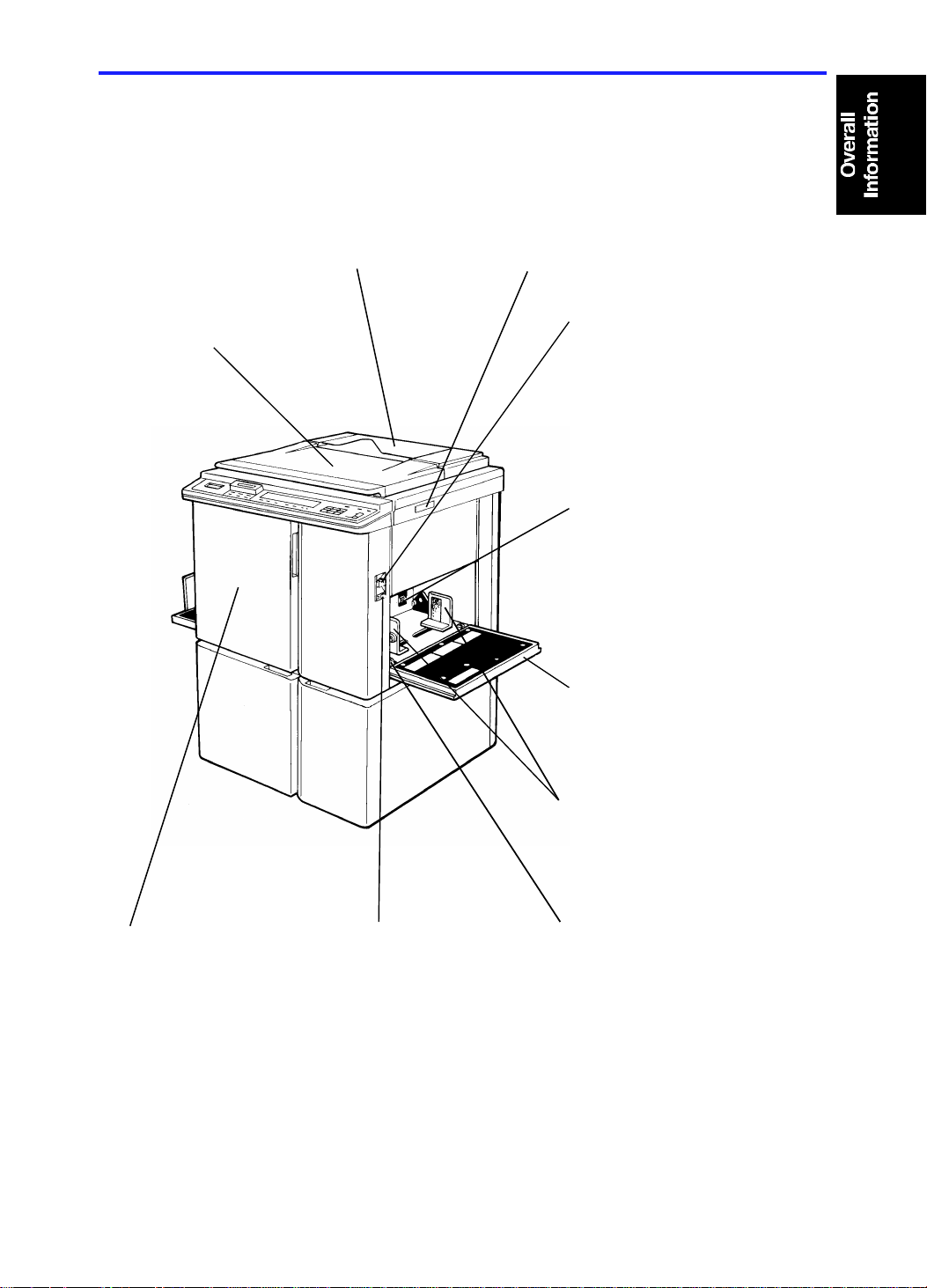
2. GUIDE TO COMPONENTS
Original Holder
A convenient place for
holding originals while
operating the mach ine.
Platen Cover
Lower this cover over
an original before
printing.
Original Table Release Lever
Use to open the original tab le
unit when installing the master.
Feed Roller Pressure
Lever
Use to adjust the contact
pressure of the paper fe ed
roller according to paper
thickness.
Separation Roller
Pressure Lev er s
Use to adjust the
separation roller
pressure to prevent
double fe ed.
Front Door
Open for access to
the inside of the
machine.
Paper Feed Table
Down Key
Press to lower the
paper feed table.
Paper Feed Table
Set blank paper o n th is
table for printing.
Paper Feed Side
Plates
Use to prevent paper
skew.
C222V501.img
Side Plate Fine
Adjustment Dial
Use to shift the
paper feed table
sideways
1-3
Page 6
GUIDE TO COMPONENTS 15 July 1995
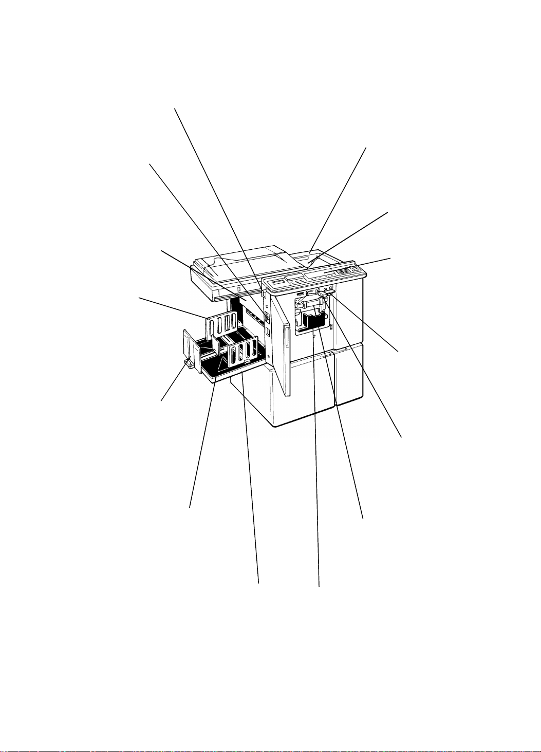
Master Eject Unit Open
Button
Press to remove misfed
paper or a misfed master.
Master Cut Button
Press this button to cut
the master paper
leading ed ge after
Main Switch
Use to turn the
power on or off.
Master Eject
Container Cover
Open when
installing a new master
roll.
Pressure Release
Lever
Use to install the
master roll.
removing the
master eject box.
Operation Panel
Operator controls
Paper Deliver y
Side Plates
and indicators are
located here.
Use to align the
prints on the
paper delivery
table.
Drum Rotation
Button
Press to replace
the drum.
Paper Deliver y En d
Plate
Use to align the
leading edges of
prints larger than A4,
81/2" x 11".
Small Size Paper Delivery
End Plate
Use to align the leading
edges of prints that are A4 ,
81/2" x 11" or smaller.
C222V502.img
Drum Unit
The master is wrapped
around this unit.
Drum Unit Lock
Lever
Lift to unlock and
pull out the drum
unit.
Paper Deliver y Tabl e
Completed prints are
delivered here.
1-4
Ink Holder
Set the ink cartridge in
this holder.
Page 7
5
6
13
7
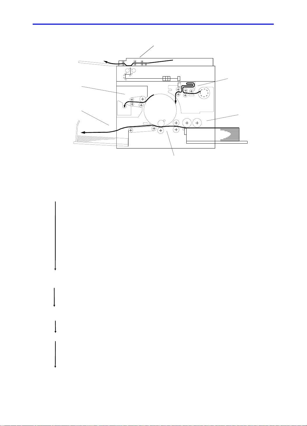
15 July 1995 MECHANICAL COMPONENT LAYOUT
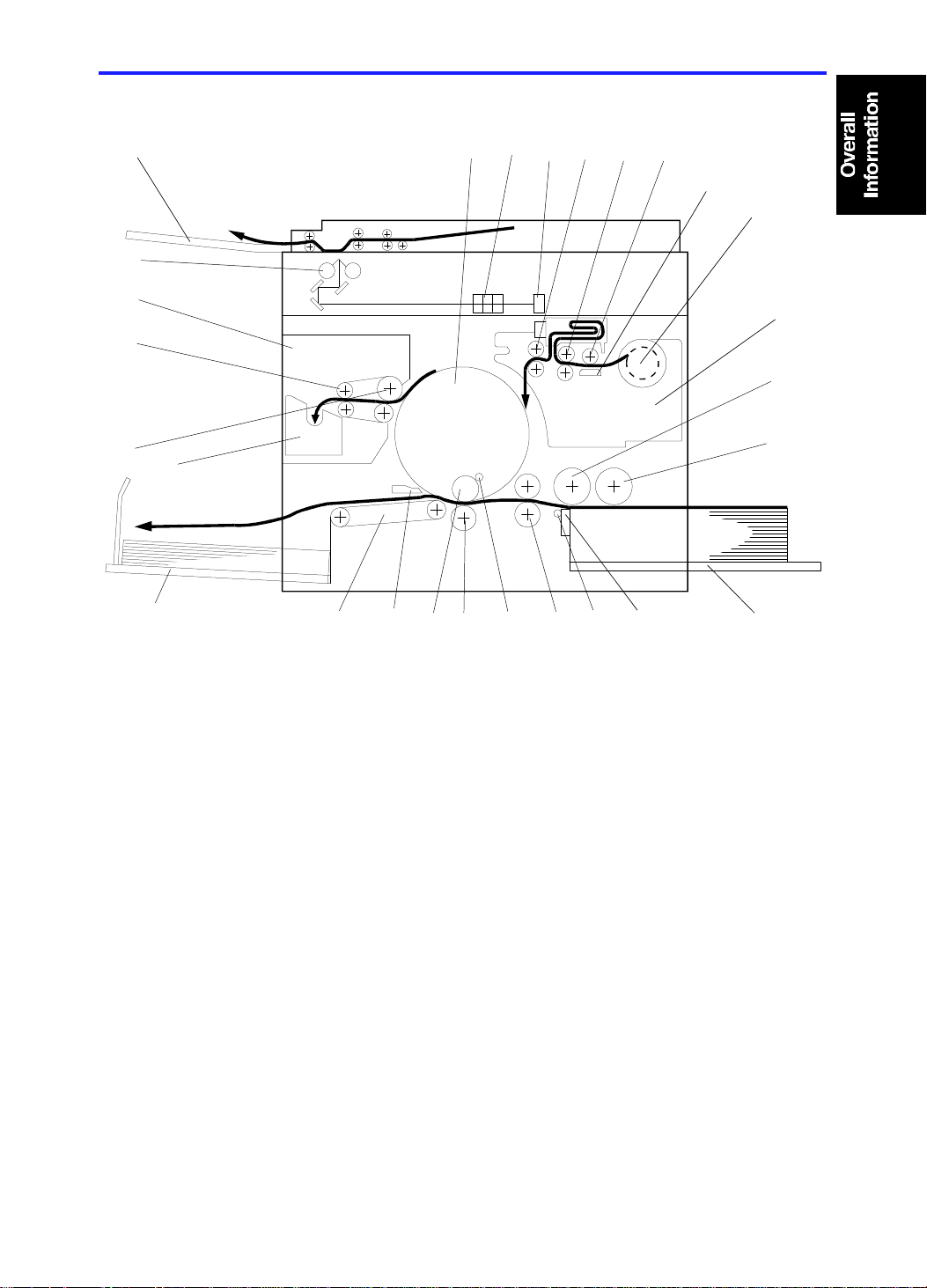
3. MECHANICAL COMPONENT LAYOUT
26
25
24
23
27
21
22
19
1234
1820
17
8
9
10
11
141516
12
1. Drum Unit
2. Lens
3. CCD
4. Reverse Roller
5. Master Feed Roller
6. Platen Roller
7. Thermal Head
8. Master Roll
9. Master Making Unit
10. Upper Separation Roller
11. Paper Feed Roller
12. Paper Table
13. Separation Pla te
14. Lower Separation Roller
C222V500-1.wmf
15. 2nd Feed Roller
16. Doctor Roller
17. Press Roller
18. Ink Roller
19. Paper Exit Pawl
20. Transport Unit
21. Paper Delivery Table
22. Master Eject Box
23. 1st Eject Roller
24. 2nd Eject Roller
25. Master Eject Unit
26. Exposure Lamps
27. Original Exit Tray
1-5
Page 8
DRIVE LAYOUT 15 July 1995
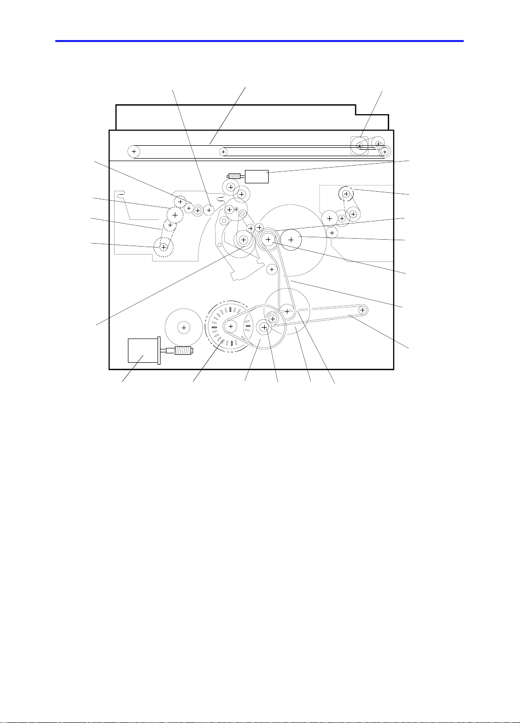
4. DRIVE LAYOUT
21
1
20
19
18
17
2
3
4
5
6
7
8
16
9
15 14
1. Scanner Belt
2. Scanner Motor
3. Image Position Motor
4. Master Eject Motor
5. Drum Drive Gear
6. Drum Unit Gear
7. Drum Drive Pulley
8. Main Drive Belt
9. Transport Belt
10. Printing Pressure Pulle y
11. Printing Pressure Gear
13
C222V504.wmf
12
11 10
12. Idle Gear
13. Idle Pulley
14. Main Motor
15. Paper Table Drive Motor
16. Paper Feed Cam Gea r
17. Master Feed Motor
18. Timing Belt
19. Platen Roller Gear
20. Master Transport Roller Gear
21. Reverse Roller Gear
1-6
Page 9

15 July 1995 ELECTRICAL COMPONENT DESCRIPTIONS
5. ELECTRICAL COMPONENT DESCRIPTIONS
INDEX
No.
Motors
15 Vacuum Fan Motor Provides suction so that paper is held firmly on the
35 Main Motor Drives paper feed, drum printing, and paper delivery
38 Paper Table Drive Motor Raises and lowers the paper feed table.
44 Image Positioning Motor Changing the relative timing of the paper feed roller
49 Master Feed Motor Feeds the master to the drum.
51 Master Buffer Fan Motor Provides suction so that the master is stored in the
52 Pressure Plate Motor Raises and lowers the pressure plate in the master
58 Air Knife Motor Drives the fan to separate the paper’s leading edge
60 Master Eject Motor Sends the used master into the master eject box.
62 Cutter Motor Drives the mechanism that cuts the master.
68 Scanner Motor Drives the 1st and 2nd scanners.
Solenoids
29 Ink Supply Solenoid Releases the spring clutch to activate the ink supply
30 Master Press Sheet Solenoid Inserts the mylar sheet between the press roller and
34 Printing Pressure Solenoid Engages the pressure on/off lever when a paper
37 Paper Feed Solenoid Releases the sector gears to feed the paper.
40 Detection Pin Release
Solenoid
45 Master Feed Clamper
Solenoid
46 Drum Lock Solenoid Prevents the drum unit from being removed during a
47
Master Eject Clamper Solenoid Open the master clamper to eject the master.
57 Master Eject Solenoid Presses the lower master eject roller against the
NAME FUNCTION
transport belt.
unit components.
and the drum to adjust the vertical image position.
master box during the master eject operation.
eject mechanism.
from the drum.
pump.
the drum during a quality start operation.
misfeed occurs.
Releases the detection pin arm to apply printing
pressure during a quality start operation.
Open the master clamper to catch the master during
master feed.
printing run.
drum surface.
Switches
1 Scanner Unit Safety Switch Cuts off the power line of the main and paper table
drive motors when the scanner unit is open.
2 Paper Table Down Button Instructs the CPU to turn on the paper table drive
motor to lower the paper table.
5 Paper Table Open Switch Checks whether the paper table is opened or not.
1-7
Page 10

ELECTRICAL COMPONENT DESCRIPTIONS 15 July 1995
INDEX
No.
7 Paper Table Safety Switch Stops lowering the paper feed table to prevent users
12 Front Door Safety Switch Informs the CPU when the front door is open, and
18 Test Switch Disables the front door, paper table, master eject
20 Main Switch Turns the power on or off.
21 Air Knife Motor Safety Switch Cuts off the power line of the air knife motor when
26 Drum Rotation Button Instructs the CPU to rotate the drum at 10 rpm.
27 Drum Unit Safety Switch Checks whether the drum unit is set correctly or not.
28 Master Eject Unit Safety
Switch
43 Master Cut Button Instructs the CPU to feed a short strip of master
50 Left Cutter Switch Detects when the cutter position is at the far left
59 Master Eject Box Switch Checks whether the master eject box is set properly.
64 Right Cutter Switch Detects when the cutter position is at the far right
74 ADF Set Switch Detects if the optional document feeder is closed.
NAME FUNCTION
from catching their fingers under it, by cutting the ac
power. It also closes when the paper feed table is
closed.
cuts off the power line to the paper table drive motor.
unit, and scanner unit safety switches.
the master eject unit is open.
Cuts off the power line when the master eject unit is
open.
paper and cut the master paper.
(operation side).
(non-operation side).
Sensors
3 Paper End Sensor Informs the CPU if there is paper on the paper table.
4 Paper Width Sensors Informs the CPU of the printer paper width.
6 Paper Length Sensor Informs the CPU of the printer paper length.
8 Paper Table Height Sensor Informs the CPU if the paper table is at the paper
feed position.
11 Paper Table Lower Limit
Sensor
13 Printing Pressure Sensor Informs the CPU if printing pressure is applied. Also,
14 1st Paper Exit Sensor Detects paper misfeeds.
17 2nd Paper Exit Sensor Detects paper misfeeds.
31 2nd Drum Position Sensor Checks the position of the drum.
33 1st Drum Position Sensor Checks the position of the drum.
36 Drum Rotation Sensor Supplies timing pulses to the CPU based on the
48 Drum Master Sensor Informs the CPU if there is a master on the drum.
53 Lower Pressure Plate Sensor Informs the CPU if the pressure plate in the master
54 Upper Pressure Plate Sensor Informs the CPU if the pressure plate in the master
55 Full Master Box Sensor Informs the CPU whether the master eject box is full
Informs the CPU if the paper table is at the lowest
position.
detects paper misfeeds.
main motor speed.
eject mechanism is at the lower limit position.
eject mechanism is at the upper limit position.
of masters or not.
1-8
Page 11

15 July 1995 ELECTRICAL COMPONENT DESCRIPTIONS
INDEX
NAME FUNCTION
No.
56 Master Eject Sensor Detects used master misfeeds.
63 Master End Sensor Informs the CPU when the master roll in the master
making unit runs out.
65 Master Buckle Sensor Informs the CPU if the master is buckling.
70 Platen Cover Position Sensor Detects when the platen cover or the optional
document feeder is opened more than 25 degrees
above the exposure glass.
73 Original Sensor Detects if an original is placed on the exposure glass.
75
Scanner Home Position Sensor Informs the CPU when the 1st scanner is at home
position.
Printed Circuit Boards
9 Main Control PCB Controls all machine functions both directly and
through other boards.
41 AC Drive PCB Controls the ac components using relays.
42 Ink Detection PCB Informs whether ink is present in the drum.
69 CCD PCB Converts light intensity into an electrical signal.
72 A/D Conversion PCB Converts analog signals into digital signals.
Counters
22 Master Counter Keeps track of the total number of masters made.
23 Total Counter Keeps track of the total number of prints made.
Others
10 Transformer Steps down the wall voltage.
16 Power Supply Unit Provides power for all dc components.
19 Circuit Breaker Cuts the ac line off.
24 Operation Panel Interfaces the CPU and the operator.
25 Drum Rotation LED Turns to green from red when the drum stops at the
home position.
32 Noise Filter Filters out electrical noise from the ac power input
line.
39 Paper Table Drive Motor
Protects the ac drive PCB from induced current.
Capacitor
61 Reverse Roller Clutch Transfers drive to the reverse roller.
65 Thermal Head Creates the master using heat.
67 Xenon Lamp Illuminates the original.
71 Xenon Lamp Stabilizer Stabilizes the power supplied to the xenon lamp.
1-9
Page 12
Master
Making/
Master
Feed
PRINTING PROCESS 15 July 1995
6. PRINTING PROCESS
Master
Ejection
Paper
Delivery
1. Master Ejection/
Scanning/
Master Making:
At the start of the print ing run, the machine
ejects the used master wrapped around the
drum into the master eject box.
Scanning
Printing
Shown with
optional ADF
attached
Paper
Feed
C222V500.wmf
At the same time, the machine scans the
original on the exposure glass (reflected light
goes to the CCD via the mirrors and the lens.
The scanned image is tran sfe rred to the master
using a thermal head.
While the old master is still being ejected, the
new master is stored in a box.
2. Master Feed: After the old master has been eject ed , th e ne w
master is fed to the drum and wrapped around
it. At the same time, the master is cut of f fro m
the roll.
3. Paper Feed: I nd ividu al she et s of pa per are fe d to the drum.
4. Printing: The paper fed from the paper fee d mech anism
is pressed onto the drum. This transfers ink to
the printer paper through the drum screen and
the master.
5. Paper Delivery: The exit pawl and air knife peel off the printout,
and the printout is ejected onto the paper
delivery table.
1-10
Page 13

SECTION 2
DETAILED SECTION
DESCRIPTIONS
Page 14
15 July 1995 MASTER EJECT
1.
MASTER EJECT
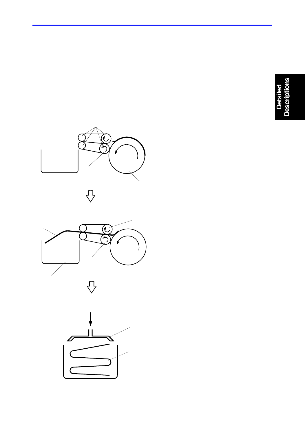
1.1 OVERALL
At the end of the printing cycle, the use d master remains wrapped around the
drum to prevent the ink on th e drum surface from drying. Whe n th e Master
Making key is pressed to make a new master, the used master is ejected
from the drum.
The master is pulled off the drum, then it goes through the eje ct rolle rs and
into the master eject box. A pressure plate then compacts the used master.
[D]
[G]
[C]
[A]
[F]
[B]
C222D505.wmf
[E]
Drum
•
The drum [B] rotates in reverse
(opposite to the printing direction).
•
The master eject rollers [A] rotate.
•
The lower eject roller [C] is
pressed against the drum.
•
The trailing edge of the master,
which curls up from the drum,
passes between the upper [E] and
lower [F] eject rollers, and the
master [D] is peeled off th e dru m
and dumped into the mast er eje ct
box [G].
C222D506.wmf
C222D507.wmf
[H]
[I]
•
The pressure plate [H] compa cts
the ejected master [I].
2-1
Page 15

MASTER EJECT 15 July 1995
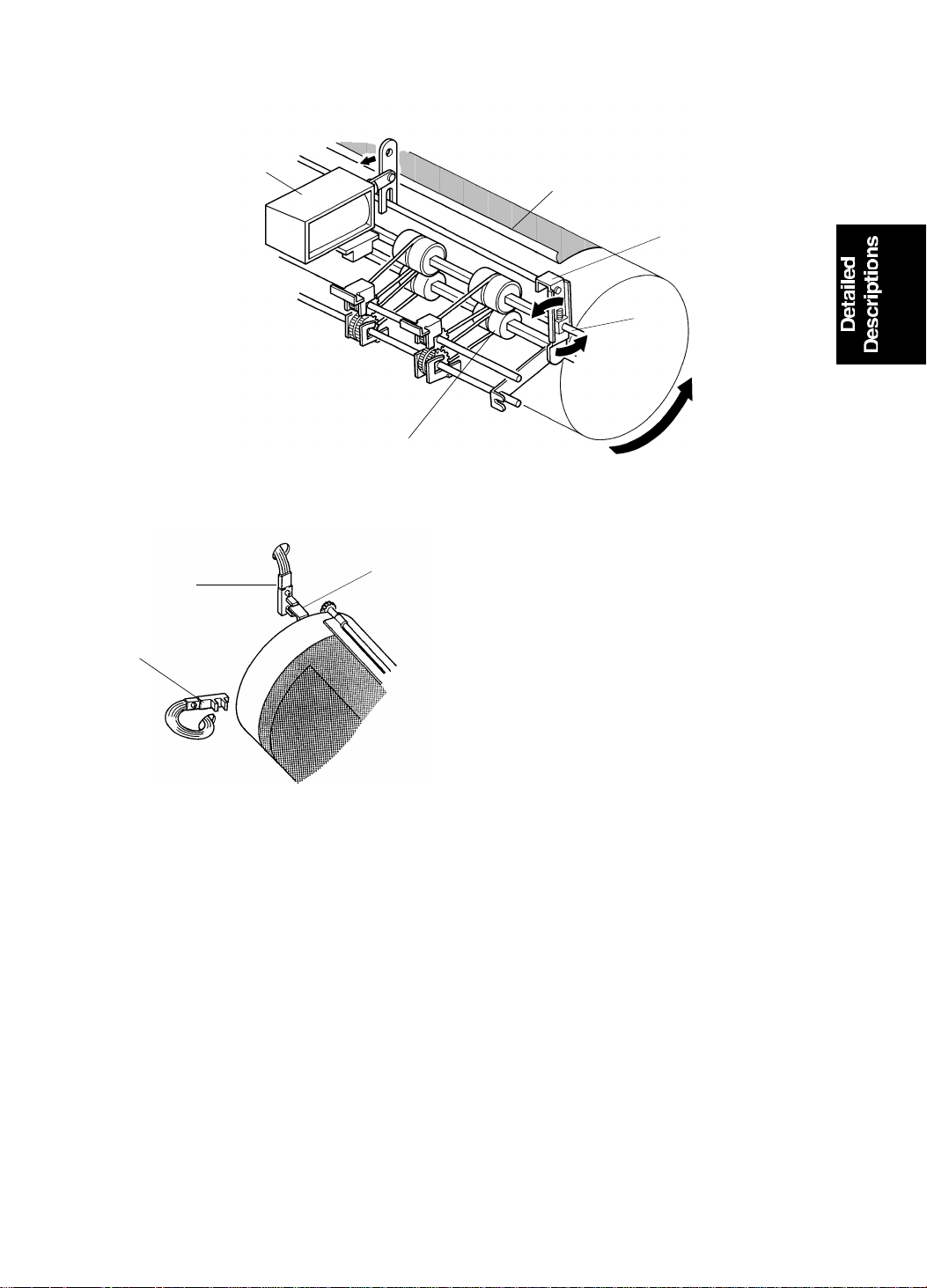
1.2 MAS TER E JE CT ROLLE R ROTATI O N MECHANIS M
[I]
[J]
[H]
[G]
[A]
[B]
[E]
[F]
[B]
[C]
[D]
[E]
[F]
C222D511.img
When an original is in place and the Mast er Making key is pressed, the main
motor starts turning at 20 rpm in re verse . As a resu lt, the drum also turns in
reverse (compared with the rotation direct ion for prin ting).
At this time, if the drum master sensor detects a master on the drum, the
master eject motor [A] starts rotating. Drive is transmitted to gear [E] and to
the upper first eject rollers [G] through the timing belt [B] and gears [C] and
[D]. Gear [F] drives the lower first eject rollers [H] . The belts [I] transmit drive
from the first eject rollers to the upper and lower second eject rolle rs [ J].
(If the drum master sensor det ect s no mast er on the drum whe n th e Mast er
Making key is pressed, the machine skips the master eject process and goes
directly to the master making process.)
After the master eject process is completed, the drum returns to its home
position. The master eject rollers then stop rotating.
This model has four rollers on each eject roller shaft.
2-2
Page 16
[D]
15 July 1995 MASTER EJECT
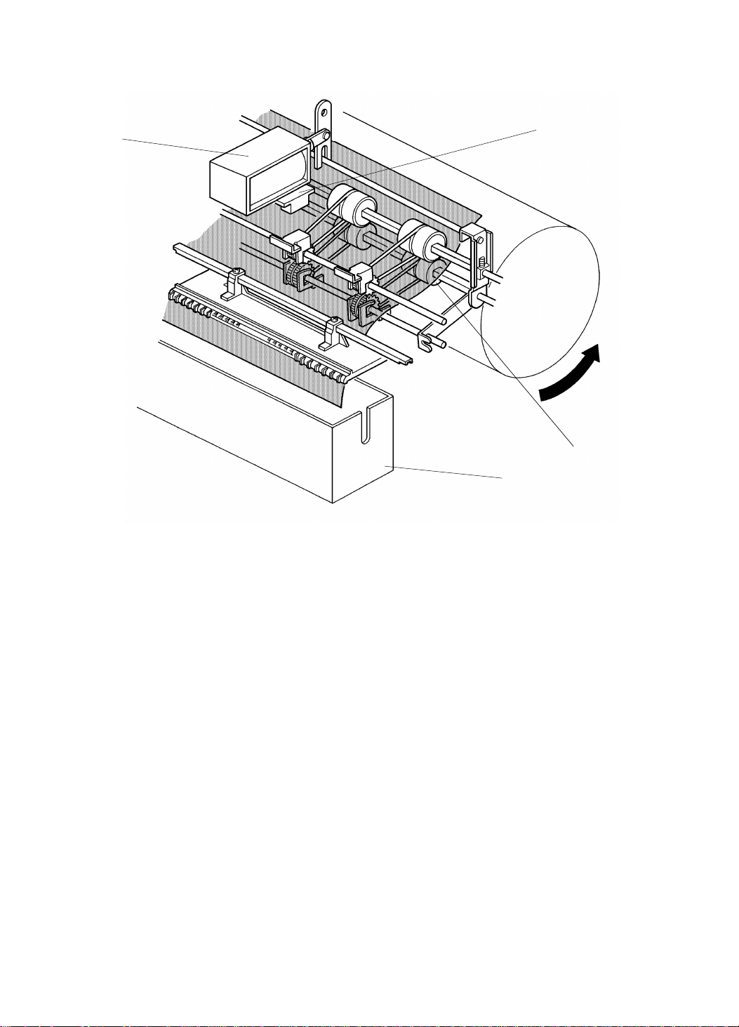
1.3 MASTER EJECT ROLLER DRIVE MECHANISM
[H]
[G]
[A]
[B]
[C]
[E]
C222D508.img
[F]
C222D510-1.img
The drum position is detected by th e first [G] and secon d [H] drum position
sensors. When the drum reach es its ho me position, the first drum position
sensor [G] is activated by the interrupter [F] on the rear side of th e drum.
To eject the master, the drum turns in reverse (opposite to the printing
direction). When the drum is 22° past the 2nd drum position sen sor, the
master eject solenoid [A] turns on and the suppo rte r [C] rotates
counterclockwise on the upper eject roller shaft [D]. This forces the lower first
eject roller [E] against the dru m.
As the drum turns, the curled trailing edge of the master [B] passes be twe en
the upper and lower first eject rollers. The first eje ct rolle rs the n peel the
master from the drum.
2-3
Page 17
[B]
[D]
MASTER EJECT 15 July 1995
[A]
[C]
C222D509.img
When the drum is 63° past the 2nd drum posit ion se nso r, the master eject
solenoid [A] turns off , sep ara ting the lower first eject rollers [C] from the drum.
Shortly after the lead ing edge of the ejected master h as passed between the
upper and lower first eject rollers, the master eje ct sen sor [B ] is a ctiva ted.
The master is then dumped into th e mast er eject box [D].
2-4
Page 18
15 July 1995 MASTER EJECT
Master Eject Misfeed Dete ction
The misfeed indicator for the master eject mechanism blinks in the fo llowing
cases:
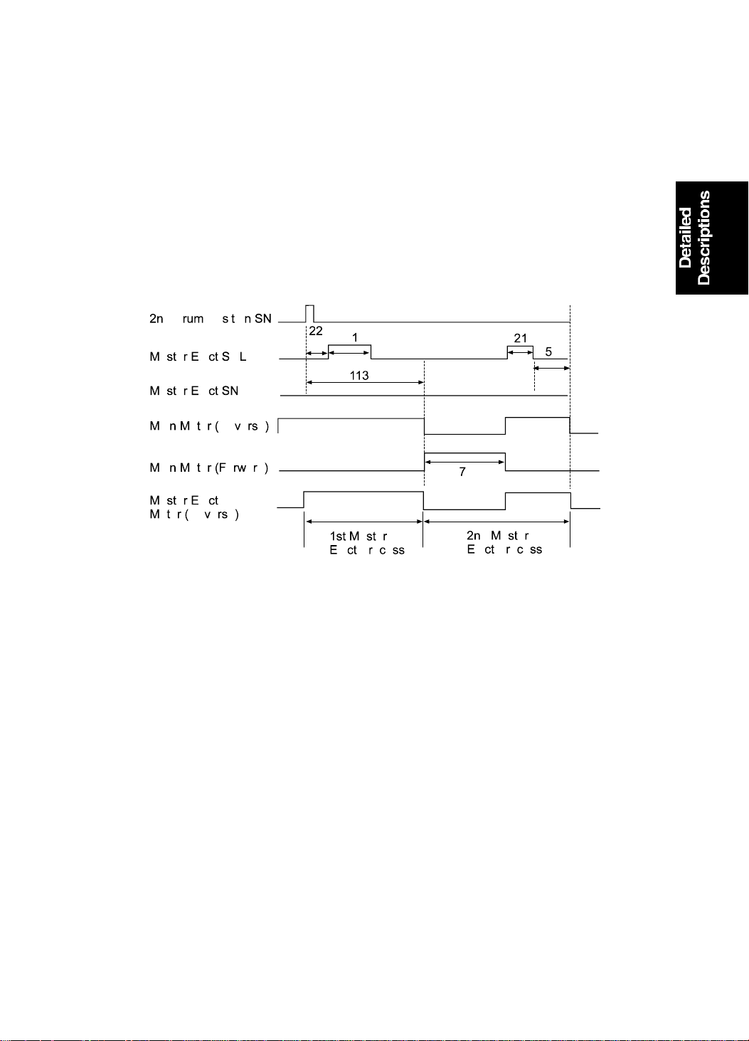
Case 1: The drum has turned 11 3 de gre es past the 2nd drum position
sensor, and the master eject sen sor is still n ot activa te d. The CPU
determines that the eject rollers ha ve fa iled to cat ch th e master. So
the drum returns 70 degrees (in the printing dire ctio n) to repeat the
master eject process. The master eject solenoid is again energized
while the drum turns another 21 deg ree s to try to catch the master.
C222D512.wmf
If the master eject sensor once again fails to detect the master,
then the drum returns to its home position and the misfee d
indicator blinks.
Case 2: The drum finishes its rotation for the master ejecting pro cess an d
returns to the home position, but the master eject sensor does not
turn off. This means that the master is still in between the master
eject rollers, and the misfeed indicator blin ks.
2-5
Page 19
[G]
MASTER EJECT 15 July 1995
1.4 MAS TER E JE CT CLAMPE R MECHANI S M
[F]
[B]
[A]
[E]
[C]
[D]
C222D513.img
When the drum has rotate d 21 4 de gre es (in reverse) past the 2nd drum
position sensor, the mast er eject clamper solenoid [A] turns on and lever [B ]
moves counterclockwise a short way as shown. This moves the cam [D]
inside the drum. Drum rotatio n brings the clamper sector gear [E] against the
cam [D]. Gear [F] turns count erclo ckwise as it en ga ges the clamper sector
gear, thus opening the maste r clampe r [G] . This rele ases the master from the
drum.
The drum keeps on turning until the interrupter at the rear of the drum has
gone 17 degrees past the first drum position sensor. Then, the main mot or
turns off. Half a second later, the master eject clamper solenoid [A] turns off
and spring [C] pulls cam [D] back to its initia l posit ion . The drum then rotates
forward to its home position .
2-6
Page 20
[A]
[C]
[D]
[E]
[F]
[G]
15 July 1995 MASTER EJECT
1.5 P RESSURE PLATE UP/DOWN MECHANISM
[B]
[M]
[L]
[K]
[I]
[H]
[J]
Pressure Plate Down
C222D514.img
When the interrupter at the rear of the drum interrupts the first drum position
sensor (this happens at th e en d of the master eject process), th e pre ssure
plate motor [B] starts. This drives gear [H] clockwise by mea ns of gears [C],
[D], [E], and [F].
Pin [I] on gear [H] moves link [G] down until the link interrupter [L] interrupts
the lower pressure plate sensor [J] . Sp ring [M] pulls down on the pressure
plate and the ejecte d master in the master eject box is compresse d by the
pressure plate [A].
If the master box full sensor [K] does not turn on when the pressu re plate
goes down, it means the master eje ct box is fille d with eject ed masters. In
this case, the master eject bo x full ind icator blinks, and the machine stop s
after a new master is wrapped around the drum.
The indicator goes out after t he master eject box switch has been turned off
and on. Then the maste r box fu ll se nso r is che cked aga in af ter one master
has been fed. This is to prevent the indicator from being reset without
removing the ejected masters from the box. When the indicato r is blin king ,
the Master Making key does not work, but the Print Start key and Proof key
work so that the master curre nt ly o n th e dru m ca n be used for printing.
2-7
Page 21
[B]
[D]
MASTER EJECT 15 July 1995
[A]
[G]
[C]
[F]
[E]
C222D515.img
Pressure Plate Up
When the master has been wrapped around the drum in the master making
process and the master cutter leaves the home position to cu t th e master, the
pressure plate moto r [B] starts rotating to raise th e pressure plate.
When the pressure plate motor [B] turns, the gear [C] is driven through the
relay gears. The pin [F] on the gear inserted into the link [D] rises and lift s the
left end of the link, thus raising the pressure plate.
The gear [C] continues turnin g until th e int erru pt er [G ] at the fron t en d of the
pressure plate blocks the upper pressu re pla te senso r [ A] . At this time , th e
master eject motor [B] stop s and the pressu re pla te is held in th e up pe r
position.
Pressure Plate Motor Lock Detection
To prevent the pressure plate motor from locking, "E-12" light s up on the
operation display panel under the following conditions:
1. When the lower pressure plate sen sor [E ] is not activa te d with in 8
seconds after the pressure plate motor starts to lower th e pressure plate.
2. When the upper pressure plat e sensor [A] is not activated with in 4
seconds after the pressure plate motor starts to raise th e pressure plate.
2-8
Page 22
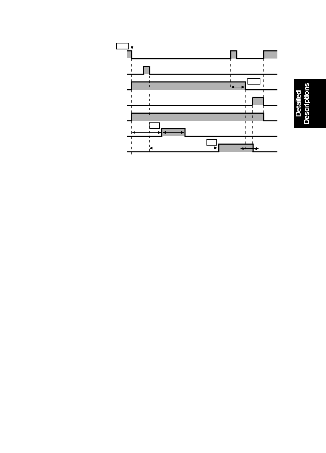
22 rpm
15 July 1995 MASTER EJECT
1.6 E LECTRI CAL TI MI NG
T1
First Drum Position Sensor
Second Drum Position Sensor
Main Motor (Reverse)
Main Motor (Forward)
Master Eject Motor
Master Eject Solenoid
Master Eject Clamper Solenoid
22 rpm 17°
T2
22°
41°
214°
T3
T4
500 ms
C222D516.wmf
T1: When the Master Making key is p resse d, the main mot or an d mast er
eject motor start. At the same time, the paper table drive motor starts to
lift the paper table to the paper feed position.
T2: When the drum has rotated 22 degrees past the 2n d dru m posit ion
sensor actuation position, the master eject solenoid is energ ized . This
presses the lower eject rollers against th e dru m surface. The master eject
solenoid is de-energized when the drum has rotated 41 degrees more.
T3: When the drum has rotated 214 degree s past the 2nd drum position
sensor, the master eject clamper solenoid is energized.
T4: When the drum has rotated 17 degrees past the drum home position, the
drum stops rotating.
500 milliseconds later (the drum complet ely stops during this period), the
master eject clamper solenoid is de-e ne rgize d an d th e drum starts
rotating forward. The dru m the n ret urn s to its home po sitio n. The mast er
eject process is now over.
Soon after this, the mach ine starts feeding a new maste r t o th e dru m f rom
the new master storage box, and the drum starts rotating in reverse to
open the clamper and begin the mast er makin g process.
2-9
Page 23
SCANNER 15 July 1995
2.
SCANNER
2.1 OVERALL
A book type scanner is used for the #C222 model. There are two mod es for
scanning originals.
Platen Cover Mode: The original is placed on the exposure glass, and the
scanner motor drives the scanner to scan the original.
ADF Mode: When an optional Documen t Fee de r is installed, the original is
fed onto the exposure gla ss. The scann er move s 22 mm away from the CCD
and remains still as it scans the original. The scanner comes back to the
home position when the scanning is finished.
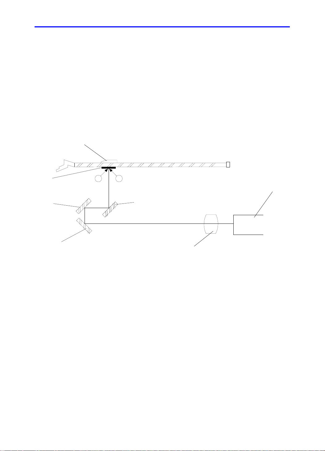
[G]
[F]
[E]
The light from the xenon lamps [A] is reflected from the orig ina l by the first
[B], second [F], and third [E] mirrors t hro ug h th e lens [D] to the CCD [C].
[I]
[A]
[A]
[B]
[D]
[C]
C222D517.wmf
In the Platen Cover Mo de , th e CCD re ad s the white plate [G] on the back of
the original scale [I] each time be fo re scanning to obtain a standa rd white
level. The standard white data are used to corre ct dist ortion. The scanner is
at its home position when it rea ds th e white level.
In the ADF mode, as the scanner move s 22 mm, th e CCD read s the wh ite
plate installed on the ADF.
2-10
Page 24
15 July 1995 SCANNER
2.2 S CANNER ME CHANI SM
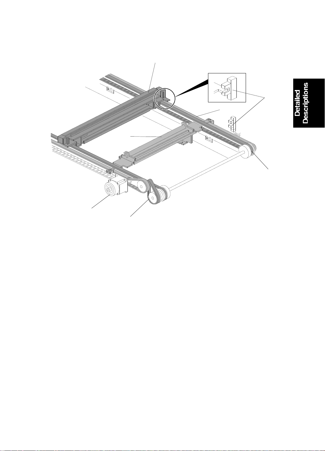
[B]
Front Side
[E]
[D]
[C]
[F]
Rear Side
[A]
[G]
C222D518.wmf
The scanner motor [A] (a stepper motor) drives the scanners. The first
scanner [B], which consists of the expo sure lamp an d th e first mirror, is
driven by the first scanner belt [F]. The seco nd scann er [C] , which consists of
the second and third mirrors, is drive n by th e second scanner belt [D]. Both
scanners move along the gu ide rails.
The timing belt [G] moves t he secon d scanner at half the speed of th e first
scanner. This is to maintain the focal distance between th e orig inal and the
lens during scanning.
The scanner home position is detected by the scanne r home position sensor
[E]. In the Platen Cover Mod e, the scann er scan s the origin al on the
exposure glass for the full A3 leng th, then returns until the scanner home
position sensor is activated . In the ADF Mode , th e scan ne r moves 22 mm
backwards (away from the CCD), to scan the original which is fed by the
ADF. When the master making process is finished and the ADF motor st ops,
the scann e r goes back to th e home positi on.
2-11
Page 25
SCANNER 15 July 1995
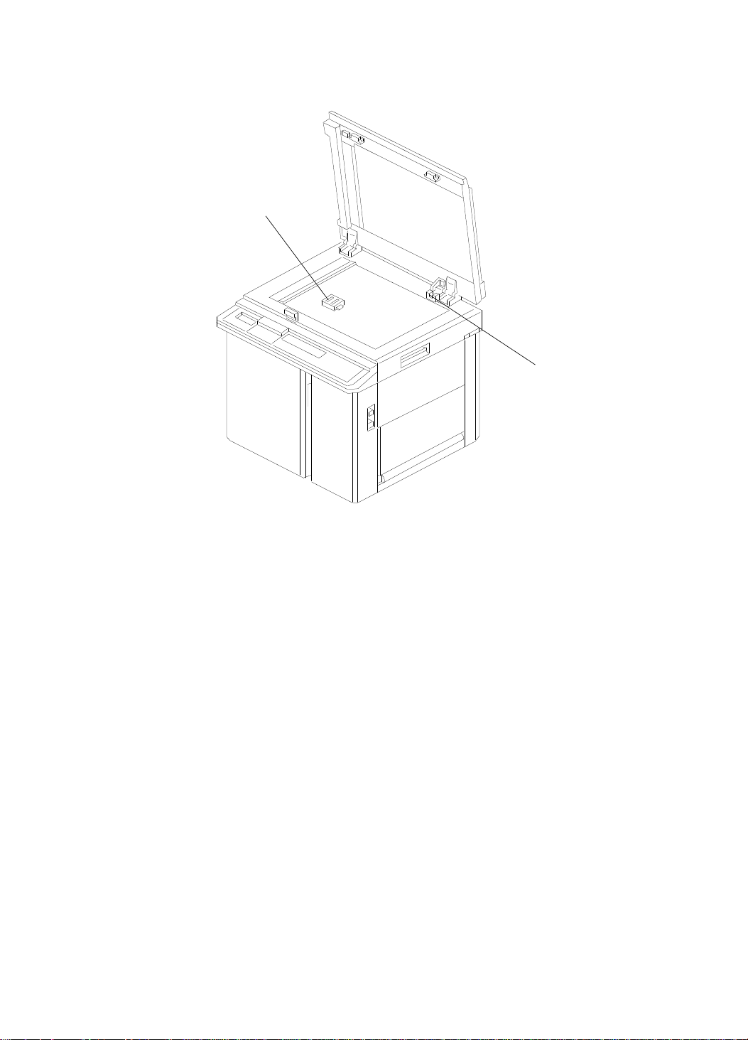
2.3 P LATEN CO VER POSITION DETECTION
[B]
[A]
C222D519.wmf
When the platen cover is opene d ab ou t 25 deg rees, the platen cover posit ion
sensor [A] is deactivat ed . Whe n this sensor is deactivated, th e original sensor
[B] is able to detect the original on the exposure glass.
If no original is detected, th e Mast er Makin g key will b e deact ivated. This is to
prevent wasting of the maste r tha t wou ld occur when a master is made
without an original.
When an original is placed on th e exposure glass and the Master Ma king ke y
is pressed with the platen cover opened more than 25 degrees (as the platen
cover position sensor is deactivate d), the shadow erase function is enabled.
2-12
Page 26
15 July 1995 SCANNER
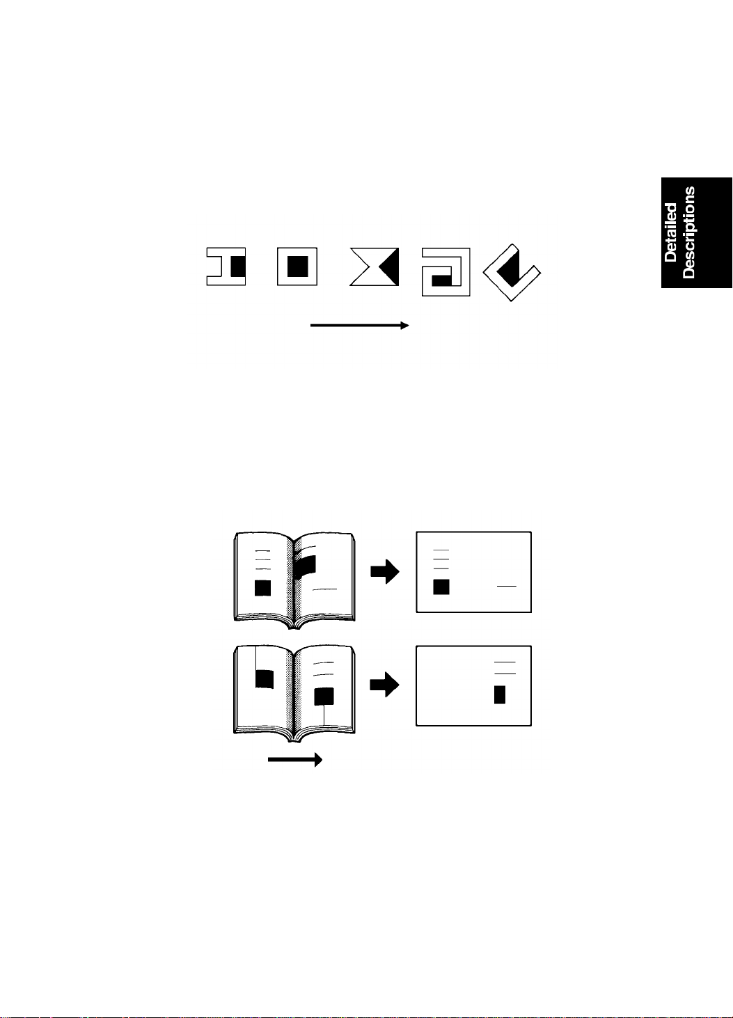
Notes regarding the shadow erase function
•
Margins of 1 mm [0.02"] on all four side s of th e orig ina l will be erase d. Th e
width of the margins will change depending on the rep rod uction ratios.
•
Shadows near the edge of a book might not be erased completely.
•
If the shape of the orig inal is as shown below, shadows might appe ar on
the prints. In this case, make the master with the platen cover closed.
Shadow
Scanning directio n
C222D520.img
•
If there is a line or solid image on the margin at the center or at the ed ge s
being erased, parts of the image might be erased as shown be low.
Scanning directio n
C222D521.img
2-13
Page 27
SCANNER 15 July 1995
2.4 E LECTRI CAL TI MI NG
2.4.1 Platen Mode
2-14
C222D522.wmf
Page 28

15 July 1995 SCANNER
Master Feed Lengths
a: 20 mm
b: 1 mm
c: 7.5 mm
d: 18.9 mm
e: 355 mm
f: 62.5 mm
g: 40 mm
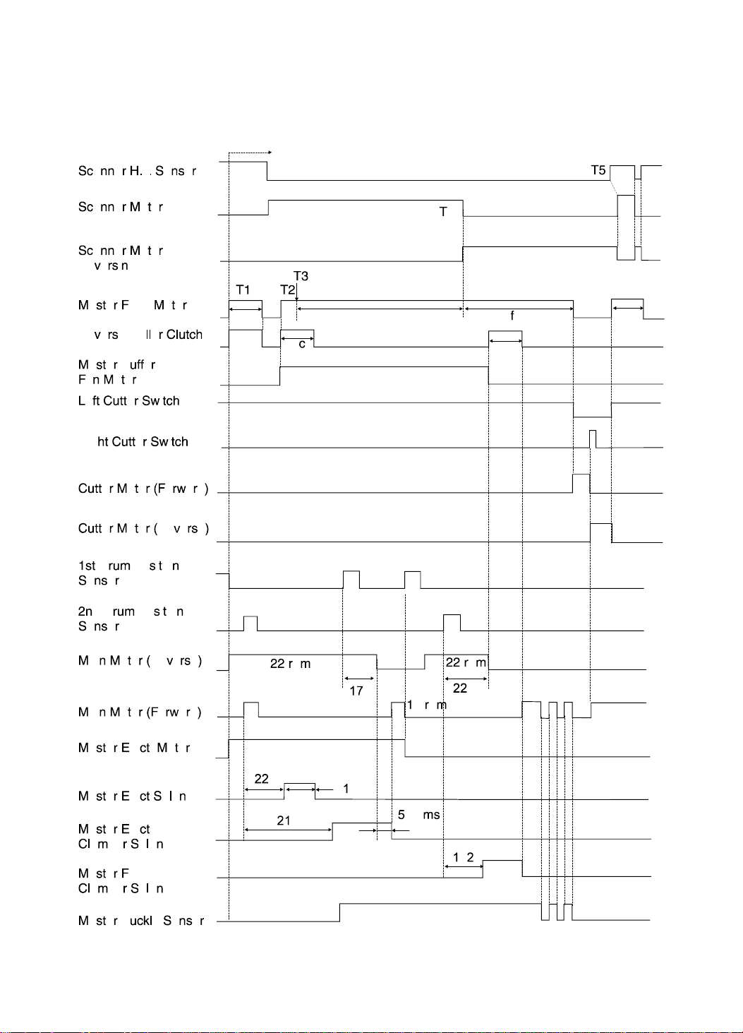
The timing chart shows how scan ning takes place at the same time as
master ejection and master making.
T1: When the master making key is p resse d, the main mot or starts reverse
rotation at 22 rpm. At the same time , the mast er fe ed moto r and the
reverse roller clutch turn on to feed th e master 20 mm. Then they switch
off, and the scanner motor tu rns on shortly afterwards.
T2: When the scanner h as move d 17 mm fro m the home position, the master
feed motor, master buckle fan motor, and the reverse roller clut ch tu rn on.
T3: The thermal head starts to make the new mast er whe n the master has
been transported 1mm.
T4: When 355 mm (the maximum scan length) has been scanned the
scanner motor starts reversing to return the scanne r t o th e ho me position.
T5: After the scanner home position sensor has been actuated, the scanner
motor rotates forward the n reve rses to stop the sca nner at the correct
home position.
2-15
Page 29
SCANNER 15 July 1995
2.4.2 ADF Mode
C222D611.wmf
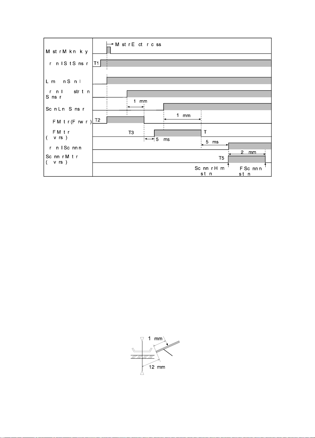
The above timing chart shows scan ne r timing when an optio na l ADF has
been installed.
T1: When originals are inse rte d in th e ADF un it, the origin al set senso r is
activated.
T2: When the Master Makin g key is pressed, the ADF motor rotates the
pickup roller and the feed roller to feed the bot to m origin al into the ADF.
T3: The ADF motor stops rotating clockwise when the origin al has bee n fed
14.0 millimeters after the original registration sensor was activated. After
50 milliseconds, the ADF motor starts rotating counterclockwise to rotate
the 1st original transport roller.
T4: The ADF motor stops again when th e orig ina l has be en fed 18 millimeters
after the scan line sensor wa s activa te d. The ADF motor waits until the
master eject process is finished.
Scan Line Sensor On
Original
ADF Scanning Position
C222D610.wmf
T5: 50 miliseconds later, the ADF motor starts reversing to bring the scanner
to the ADF scanning position.
2-16
Page 30
15 July 1995 MASTER FEED
3.
MASTER FEED
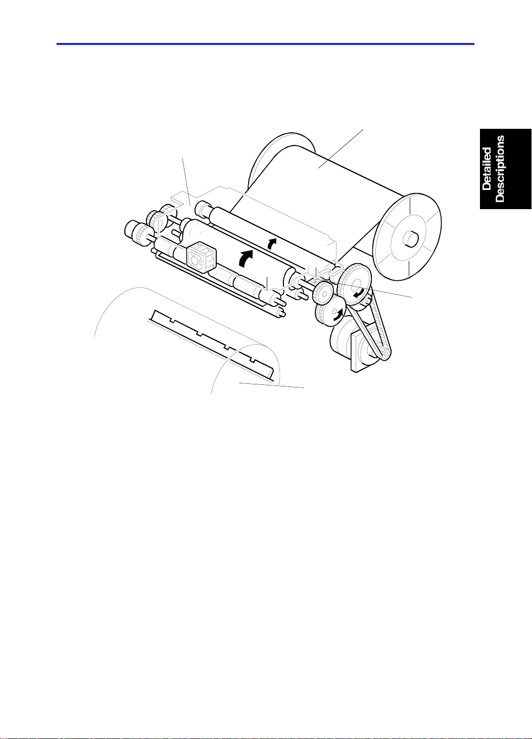
3.1 OVERALL
[A]
[D]
[B]
[C]
C222D500-1.wmf
The thermal head [B] burns the imag e (scan ned by th e CCD) onto th e mast er
[A] as it is being fed to the dru m [ C]. Th e use d master is ejected at the same
time that the new master is printed, and the new master is stored in the
master box [D] until the old master ha s bee n comp let ely eje cted. The master
is then clamped to and wrapped around the drum.
The master box mechanism reduce s the amou nt of time neede d to ma ke a
new master, because the new mast er can be mad e at the same time tha t the
old one is fed out.
2-17
Page 31

MASTER FEED 15 July 1995
3.2 MASTER FEED CLAMPER OPENING MECHANISM
[A]
[B]
[C]
C222D512-2.img
[G]
[F]
[H]
[D]
[E]
C222D526.img
After the master eject pro cess is finished and the interrupter [A] is positio ned
in the first drum position senso r [B] , th e main moto r turns on and the drum
starts rotating (22 rpm) in reverse (opposite to the printing direction).
When the drum has turned 162 degrees past the actuation position of the
second drum position senso r [C], the master feed clamper solenoid [D] turn s
on, and the cam [H] moves inside the drum.
When the drum has turned another 58 degrees, the sector gear [F] rotate s
upwards as it contacts the cam [H] . This en ga ges the secto r gea r wit h gear
[E], which turns counterclockwise to open the clamper [G]. At the same time,
the drum stops and the clamper remains open to cat ch and clamp the
master’s leading edge.
2-18
Page 32

[A]
15 July 1995 MASTER FEED
3.3 MASTER FEED MECHANISM
[D]
[B]
[C]
[E]
C222D500-2.wmf
C222D501.wmf
To minimize the first print time, the maste r ma king proce ss starts just after
the master making key is pressed.
When the master making key is pressed , th e drum starts rotating in reverse
to eject the master that is wrapped aro und th e dru m. At the same time , th e
master feed motor [A] sta rts tu rning and the reverse roller clutch [B] is
energized.
When the master has been transported 20 mm, the master feed roller and the
reverse roller clutch stop. They sta rt ag ain just af ter original scanning starts.
When the master has been transported a further 7.5 mm (when the leading
edge is 6 mm past the reverse roller [C]), the reverse roller clutch is turned off
but the master feed mot or continues to rotate. As a re sult , the master leading
edge stays at 6 mm past the reverse roller, and the ma ste r buckles up behind
the reverse roller. Until the drum comes to the maste r fee d positio n, the new
2-19
Page 33

MASTER FEED 15 July 1995
master fed by the master feed motor during the eject process is stored in the
master box [D]. The suction provided by the master buffer fan motor [E] helps
to bring the master into the box.
The main results of this mechanism are:
•
A much greater length of new mast er can be made be fore it starts to be
wrapped around the drum.
•
The new master can start to be mad e much earlier during the machine ’s
operation cycle, saving time.
The master buffer fan mot or tu rns on when maste r ma king starts, and it stays
on until the reverse roller starts feeding the master again to be caught by the
master clamp on the drum.
2-20
Page 34

15 July 1995 MASTER FEED
3.4 MASTER WRAPPING MECHANISM
[B]
[A]
[B]
[E]
[C]
[D]
C222D502.wmf
[C]
[D]
C222D503.wmf
When the drum stops at the master feed position (at this time , th e mast er
clamper is open), the reverse rolle r clutch [A] turns on again. When the
master has been transported 18.9 mm and the master leading edge has
reached the master clampe r, th e reverse roller clutch and the master feed
clamper solenoids turn off . The maste r le ad ing edg e is clampe d by th e
master clamper.
After the master clamper catches the master leading edge, the drum rot at es
at 22 rpm while the master buckle sensor [B ] is o n. The mast er fe ed motor
continues to feed the master at this sta ge . The drum pulls t he master faster
than the master feed motor feeds it, so the maste r b uckle senso r will
deactivate eventually. When this happen s, the main moto r stops unt il the
sensor is activated by the maste r buckle again. In this way, the master is
wrapped around the drum keeping a buckle between the reverse ro ller [C]
and the master feed roller [D]. This buckle prevents the master that is still
2-21
Page 35

MASTER FEED 15 July 1995
under the thermal hea d fro m being pulled; if a long master is bein g made, this
will adversely affect copy quality.
When the new master is finished, th e mast er fe ed spee d incre ase s (t o 4
times the master making speed) and the maste r cutter cuts the master when
the appropriate length of ma ste r has be en transported.
Even if a master eject jam occurs, the master making operation continues.
When a master eject jam is detecte d, the machin e stops after master making
and cutting is done (during th is period, the new master is stored in the master
box [E]). When the reset key is pressed after the jammed master is remove d,
the reverse roller clutch turns on to tra nsp ort the maste r t o the mast er
clamper, and the master clamp er clamp s t he lead ing edg e. The drum rotates
at 22 rpm to wrap the master.
2-22
Page 36

15 July 1995 MASTER FEED
3.5 CUTTER MECHANISM
[A]
[E]
[C]
[D]
[A]
[B]
[B]
C222D527.img
[F]
[G]
C222D528.img
After the master makin g pro cess is finished, the master feed mo to r turns off
and the cutter motor [A] sta rts tu rnin g.
The cutter motor [A] starts turning in reverse (see the arrows) when the cutter
holder [B] pushes the left cutt er switch at th e front (o peration side) end of the
cutter rail; this is the cutter holder home position. This drives the cutt er ho lde r
[B] toward the rea r (non -operation side) by means of the gear/pulley [C] and
the wire [D] on which the cutter h old er [B ] is f ixed .
When the cutter holder reaches the rear end of the cutter rail and pushes the
right cutter switch, the cutter moto r [A] changes its rota tio n dire ctio n, and the
cutter holder [B] start s mo ving toward the front. The cutt er motor [A] stops
turning when the cutter ho lde r [B] is back at its home po sitio n an d pu she s the
left cutter switch. The ma ste r cutting process is now finished.
While the cutter hold er [B] is traveling to the rear, th e roller [E] in the cutter
holder is turning clockwise because it to uch es th e cut te r rail. The roller [E]
rotates the cutter blade [F] as ind icat ed by the arrow. Th e master is b et wee n
the blade and blade plat e [G] and as the cutter moves, it cuts th e master. The
blade plate also serves as a lower guide plat e for the master.
After the master cuttin g process is finished, the master is fed anoth er 40
millimeters and the master feed process is finished.
2-23
Page 37

MASTER FEED 15 July 1995
3.6 ELECTRICAL TIMING
2-24
C222D609.wmf
Page 38

15 July 1995 MASTER FEED
Master Feed Lengths
a: 20 mm
b: 1 mm
c: 7.5 mm
d: 18.9 mm
e: 355 mm
f: 62.5 mm
g: 40 mm
– Master Feed –
T1: When the master making key is p resse d, the main mot or starts reverse
rotation at 22 rpm. At the same time , the mast er fe ed moto r and the
reverse roller clutch turn on to feed th e master 20 mm. Then they switch
off, and the scanner motor tu rns on shortly afterwards.
T2: When the scanner mo to r h as move d 17 mm fro m the home position, the
master feed motor, master buffer fan mot or, and the reverse roller clutch
turn on.
T3: The thermal head starts when the maste r h as been tran spo rted 1 mm.
T4: When the master has b een transported 479.5 mm, the maste r f ee d mot or
stops. At the same time, the cutter motor starts rotating to cut the ma ste r.
When the right cutter switch is actuated, th e cutte r moto r start s reversing.
When the left cutter switch is actuat ed , th e cut te r moto r stop s.
T5: When the left cutter switch is actuated, the master feed motor start s
again to feed the master 40 mm.
– Master Wrapping –
T6: After the master eject operation is finished, the ma in mot or rot at es in
reverse at 22 rpm. The main motor stop s when the drum has ro ta te d 22 0
degrees.
T7: When the drum has rotated 162 degree s past the 2nd drum position
sensor, the master feed clamper solenoid turns on.
T8: When the drum stop s at the master feed position, the master buffer
fan motor turns off. At the same time the reverse roller clutch is
de-energized. When the master has been transport ed 18. 9 mm, th e
reverse roller clutch and the master f eed clamp er solenoid turn off.
T9: When the master has b een clamped, the main motor start s ro ta ting to
wrap the master around the drum. The motor rotat es at 22 rpm only when
the master buckle sensor is activate d.
2-25
Page 39

PAPER FEED 15 July 1995
4. PAPER FEED
4.1 OVERALL
[A]
[B]
[F]
[C]
[D]
[E]
C222D602.img
This mechanism uses a center separation system, which consists of the
separation plate [F], up per se paration roller [B], and lower separa tio n rolle r
[E]. Because of the sepa rat ion system, if a few sheets of pape r are picke d up
from the paper stack (on the paper ta ble) by the paper feed roller [A], only
one sheet of paper is transported to the second upper feed rolle r [C] and
second lower feed roller [D].
2-26
Page 40

15 July 1995 PAPER FEED
4.2 PAPER FEED ROLLER/UPP ER SEPARATION ROLLER
MECHANISM
[A]
[C]
[B]
[M]
[L]
[K]
[D]
[E]
[F]
[J]
Viewed from the
non-operation side
[I]
[H]
[G]
C222D603.img
The main motor drives the pape r fee d roller ca m [C], wh ich move s the secto r
gear back and forth. The secto r gea r [J] rotates the paper feed roller [M] an d
the upper separation rolle r [A] . A on e-wa y clutch inside gear [H] prevents the
rollers from rotating in reve rse during the return half of the sector gea r
movement cycle. The cam ro ta tes once per sheet of paper.
When the paper feed solenoid [G] turn s on, it pulls th e link [F] away fro m the
sector gear to allow it to rotate. When the cam roller [D] is at the widest part
of the paper feed roller cam [C], the sector stopper [E] drops away in a
counterclockwise direction as a cleara nce is formed between the stopper and
pin [I]. Then, the cam roller [D] on the sector gear is able to move along the
surface of the cam [C]. The solenoid [G] stays on during the copy cycle.
When the narrowest part of the paper feed roller cam [C] is rotating away
from the cam roller [D] and the wide st pa rt is app roa chin g, the sector gear [J]
turns clockwise and the gear [H] is turned counterclockwise. The rotation of
the gear [H] is transmitted to the uppe r sepa rat ion ro ller sha ft [B] , an d the
upper separation roller [A] turns coun terclockwise. At the same time, the
pulley [K] on the upper separation roller shaft [B] turns, and the belt [L]
rotates the paper feed roller [M] counterclockwise to feed the print ing paper.
When the narrowest part of the paper feed roller cam [C] appro ach es th e
cam roller [D] again, the sector gear [J] turns cou nt erclo ckwise and the gear
[H] is turned clockwise. However, a one-wa y clutch inside the gear [ H]
prevents the upper separa tio n [A] and paper feed rollers [M] from turn ing .
2-27
Page 41

PAPER FEED 15 July 1995
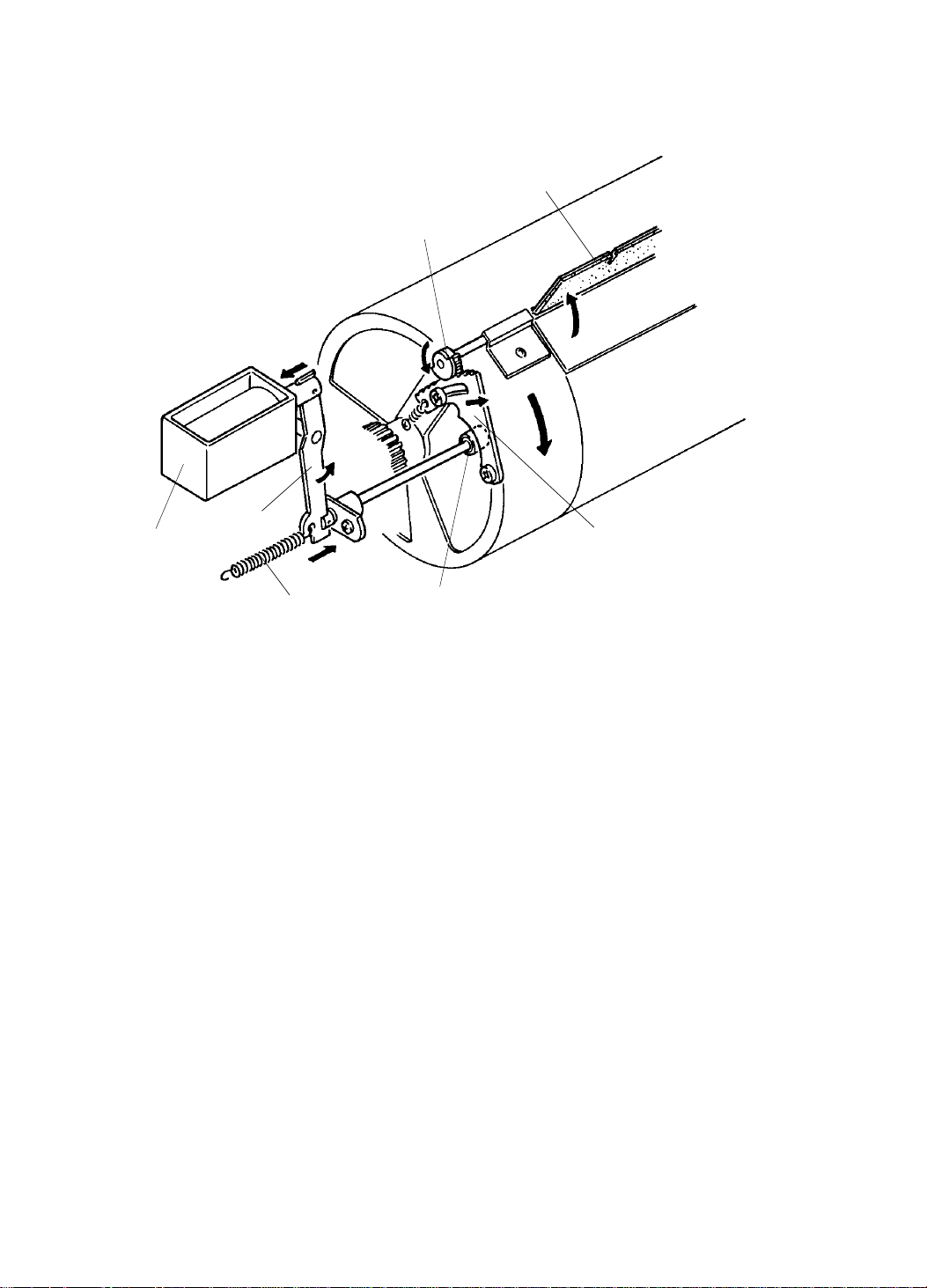
4.3 FEED ROLLER PRESSURE MECHANISM
[B]
[C]
[A]
C222D606.wmf
The feed roller assembly rot at es freely around its shaft, and th e weight of the
feed roller assembly [C] presses the paper feed roller down on the paper
stacked on the pap er table.
The spring [A] pulls the feed roller assembly upwards. When the feed
pressure lever [B] is moved up , th e tension in spring [A] increase s,
weakening the feed roller pre ssure .
The paper feed pressure can be chan ge d, and has th ree possible settings
(this is a user-level adjustment). In a new machin e, the feed pre ssure lever is
in the middle position. Whe n th ick p aper is used and paper is often not fed,
push down the feed pressure lever. The feed roller pressure will increase.
When thin paper is used and paper multi-feed often occurs, push up the lever
to decrease the feed roller pre ssure .
2-28
Page 42

[C]
15 July 1995 PAPER FEED
4.4 PAPER SEPARATION MECHANI SM
[A]
[B]
[D]
[A]
[C]
[E]
[G]
[F]
[D]
C222D604.img
Pressure from spring [F] ho lds th e separation plate [G] aga inst the upp er
separation roller. A rubber pa d on top of the sep ara tio n pla te allows only a
few sheets of paper to reach the lowe r sepa rat ion roller. If too many sheets of
paper are fed to the lower separation roller at the same time , th e lowe r
separation roller may not be able to separate the sheets; it can separate only
two or three sheets of pap er.
Springs pull lever [A] and this push es up the lower separation roller [E]. Then
this roller presses the sheets to be fed again st th e uppe r sepa rat ion roller [B].
Also, the lower separation roller does not turn in the paper feeding direction.
(It turns in the opposite direction due to the one-way clutch bearings [D]
provided on both right and left sepa rat ion le vers [A ]. ) Wh en two or more
sheets of paper are fed, a brake force is applied to the lowe r shee ts of pap er
due to the friction between the paper and the lower separatio n rolle r. The n,
the sheets are sepa rated and one sheet of pap er is f ed to the second feed
rollers.
The pressure between the upper and lower sep aration rollers can be
adjusted by changing the right and left separation pressure adjusting levers
[C] as follows (this is a user-level adjustment):
Levers Up: Separation pressure decreases.
Levers Down: Standard position.
When dog-eared or wrinkled prints are delivered, the separation pressure
should be decreased.
2-29
Page 43

PAPER FEED 15 July 1995
Fig. 2
"E"
Fig. 1
[C]
[A]
[B]
[A]
[C]
[D]
View from "E"
C222D523.img
[F]
[G]
C222D524.img
The lower separation roller [C] turn s slight ly (see the arrow in Fig. 2) due to
the one-way clutch bearings when pa pe r passe s through the roller. The lower
separation roller [C] and its shaf t [D] are pushed down slightly by the paper
[B] when the upper separatio n rolle r [ A] is feeding the paper (Fig.1). Just
when the paper is fed out from the rollers, the lower separation roller [C] and
its shaft [D] spring back again st rolle r [ A] (Fig. 2). This ro ta tes the lower
separation roller and ensure s tha t it will wear eve nly.
Four paper guide rollers [G] are th ere to red uce curl in the paper’s leading
edge, and to feed the pap er smoo thly to the guide plates. Th ere are four
marks on the bracket [F] correspo nd ing to th e roller positions as shown in the
lower diagram.
2-30
Page 44

15 July 1995 PAPER FEED
[A]
[B]
C222D529.img
[C]
C222D530.img
The side pads [A] in the fron t an d rear paper side guides preven t multiple
feed. These are especia lly u sef ul when thin paper is used. After ad justing the
paper side plates to the prop er pa pe r width (so that they touch the pap er
lightly), move the front and rea r sid e pad levers to the right (as viewed from
the operation side of the machine). Normally, the pressure from the side pads
should be released by moving the levers to the left.
The separation plate pressure can be adjust ed to mat ch the type of paper
being used. The plate which sup po rts the pre ssure plate spring [B] can be
moved up or down by turning th e eccentric cam shaft [C] (this is a
service-level adjustment only).
If multiple paper feed freq ue ntly occurs, the plate should be move d up .
If paper misfeeds frequently, the plat e should be moved down.
2-31
Page 45

PAPER FEED 15 July 1995
4.5 SEPARATION ROLLER PRESSURE RELEASE
MECHANISM
[A]
[B]
[C]
[D]
[E]
C222D605.img
When printing is finished or a misfe ed occurs, the paper table drive motor
rotates for 500 milliseconds to lower the paper ta ble . The paper on the paper
table moves down from the pape r fee d roller [ D] and the paper feed bracket
[A] is pulled down by its own weight.
At this time, the shaft [B] pushes down the left separation lever [C] and this
moves the lower separation roller [E] slightly downward.
This mechanism makes it easier to remo ve pape r caug ht bet wee n th e up pe r
and lower separation rollers.
2-32
Page 46

15 July 1995 PAPER FEED
4.6 SECOND FEED ROLLER MECHANIS M
[A]
[J]
[B]
[I]
[H]
[C]
[D]
[E]
[G]
[F]
[K]
C222D531.img
Drive Mechanism
The main motor drives the lowe r secon d feed roller cam [A], which moves the
sector gear [C] back and fort h. The sect or ge ar [C] ro ta te s the lower second
feed roller [I]. A one-way clutch inside the feed roller gear [E] prevents the
roller from rotating in reve rse during the return half of the sector gea r
movement cycle. The cam ro ta tes once per sheet of paper.
When the paper feed solenoid [G] turn s on, it pulls link [F] , th e 1st paper fe ed
roller sector gear stopper [H], an d th e 2n d fe ed roller sector gear stopper [K].
The bearing [J] on the sect or ge ar moves along the cam surface. Whe n the
widest part of the cam come s to th e be arin g [J], the stopper [B] is relea sed
from the sector gear as a clearance is formed between the pin of the secto r
gear [D] and th e stopper [K].
When the feed roller gear turns counterclockwise, its rot at ion is not
transmitted to the lower second feed roller due to the one-way clut ch bearing
in the gear.
When the narrowest part of the second feed roller cam moves away from the
bearing [J], the sector gear turns counterclockwise and the feed roller gear
turns clockwise. As the rotation of the feed roller gear is tra nsmit ted to the
lower second feed roller, the lowe r second feed roller turns clockwise to feed
the paper to the drum.
2-33
Page 47

PAPER FEED 15 July 1995
[B]
[A]
[C]
[G]
[H]
[F]
[A]
[D]
[E]
C222D542.img
Release Mechanism
This mechanism releases the uppe r seco nd feed rolle rs [B] from the lower
one [G] after the press roller and the drum catch the paper leading edge.
The mechanism is made up of several parts. First , a cam which tran smits
motion to a sector gea r [ F]; the n another cam [E] that is part of th e sect or
gear. This cam pushes a bearing [D], which causes the lever [H] attached to
this bearing to turn the upper feed ro ller sha ft [C] so th at the upper rolle rs
contact the lower rollers.
At the beginning of each cycle the upper and lower rollers are away fro m
each other. They come tog et he r halfway through the cycle and at th e en d of
the cycle they separate again.
At first, the rollers are sep arate, and the sector gear [F] is ready to start
moving clockwise. The bearing [D] on th e leve r [ H] is in cont act with the cam
[E] on the sector gear. As the gear turn s clo ckwise, it causes the cam to turn
the lever in the same direction (clockwise).
The lever then lowers the upper rolle r [B] . It doe s this by tu rnin g the roller’s
eccentric shaft [C]. The sha ft is a little off center, so when the shaft turns the
roller, the roller moves up or down.
2-34
Page 48

15 July 1995 PAPER FEED
When the cycle is halfway through, the sector gear has reached its maximum
clockwise position. Now the upper roller touche s the lower one and a pair of
springs [A] apply tension at each en d of the upp er rolle r. Until now the lower
roller has not turned.
At this point, the paper arrives from the first paper feed rollers. The lea din g
edge hits the two rollers and the paper buckles slightly. This ensu res th at the
paper will go into the rollers straight.
The lower roller now begins turnin g and feeds the paper to the drum section.
The sector gear is now turning cou nterclockwise, raising the upper roller. The
gear returns to its original position and the cycle is now over.
Service Note
The paper buckles slightly as the leading edge of the paper arrives from the
first paper feed rollers before the second paper feed rolle rs start to turn. The
second feed roller start timing can be adjust ed to cha nge th e leading edge
margin. See "Removal and Adju stme nt : Se cond Feed Roller Start Timing".
2-35
Page 49

PAPER FEED 15 July 1995
4.7 PAPER TABLE SIDE ADJUSTMENT MECHANIS M
[B]
[A]
[C]
[G]
[D]
[F]
[E]
C222D532.img
The shaft [D] of the fine adjustment dial [F] is threa de d. The inside of the
sleeve [E] is also thread ed . The sleeve is fixed to the paper table stay [B ]
through a bracket [A].
The paper table bracket [C] mounted under the table is fixe d to bot h en ds of
the adjustment dial shaft . Whe n th e adjust ment dial is turned clockwise, the
feed table bracket [C] and the paper table move to the right.
The indicator [G] fixe d to the bracket [A] shows how much the pap er table
has moved.
2-36
Page 50

15 July 1995 PAPER FEED
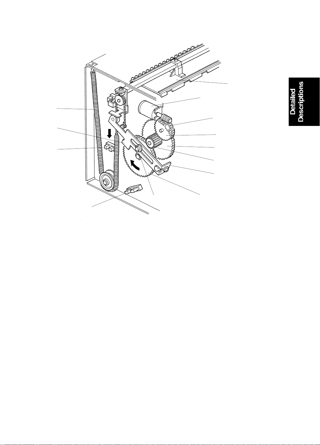
4.8 PAPER TABLE UP/DOWN MECHANISM
There are diagrams of this mecha nism on the following page.
The paper table is raised and lowere d by th e pa per t able drive motor.
The paper end sensor [E] (a reflective photosensor) is actuated when the
paper is placed on the paper ta ble. When the Print Start key is pre ssed , the
paper table drive motor [H] starts turning clockwise an d the worm gear [G ]
also turns. The worm wheel [F] turns clockwise and both gears [D] tu rn to
raise the racks [C].
As the paper table rises, the paper pushes against the paper feed roller [I] .
This raises the lever [J] which is mount ed on the pa per f eed bra cket . This
activates the paper table height sensor [K] (the phototransistor detects the
light from the photocoupler, which up to now was cut off by the lever), and
that causes the paper t ab le mot or [H] to turn off and stop raising the paper
table.
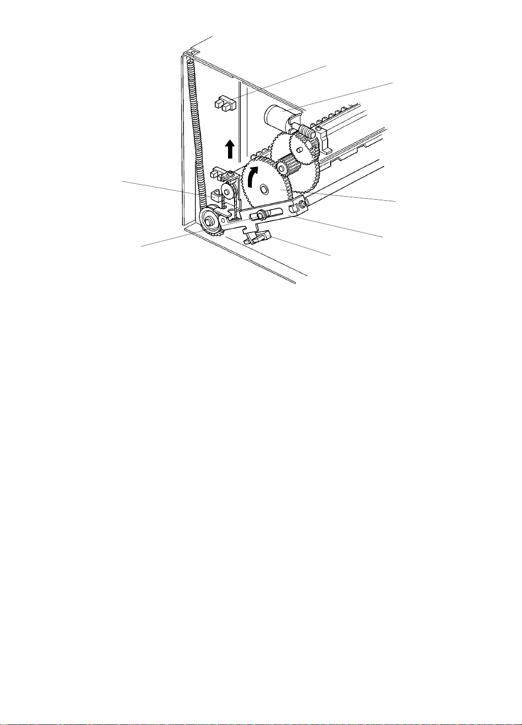
As printing proceeds and the paper level runs down, the lever [J] cuts off th e
light path in the photocoupler and the motor [H] turn s clockwise until th e
phototransistor is react ivat ed . As a resu lt, the top of th e pa per st ack is
constantly kept at the correct heig ht .
When no paper is present, the pap er en d sensor [E] is not activated and the
motor [H] turns counterclockwise to lower th e paper table. The paper table is
lowered until the actuator [A] (fixed to the front rack) interrupts the lower limit
sensor [B].
When a misfeed occurs or printing is finished, the paper table motor [H] turns
counterclockwise for 500 milliseconds, slightly lowe ring the paper ta ble .
2-37
Page 51

[J]
[K]
PAPER FEED 15 July 1995
[C]
[D]
[A]
[E]
[C]
[D]
[B]
[F]
[G]
[H]
C222D533.img
[I]
C222D534.img
2-38
Page 52

15 July 1995 PAPER FEED
4.9 PAPER SIZE DETECTION
The machine determines the printing area of the ma ste r based on the
detected paper size and th e original length (which is detected during the
original scanning process). If th e original size is different from the paper size,
the machine compares the lengths of the original and the paper. The
master’s length will be the shorter of the two. Th e printing width of the master
is determined by the paper width.
Note: The determined master printing area is not changed if the paper on
the paper table is replaced with another size of paper during the
master making process.
The printing area of the maste r for ea ch dete cte d pa per size is as follows:
Paper Size Printing Area of the Master
Width (mm) Length (mm)
A3
B4
A4
A4-S
B5
B5-S
A5
DLT
LG
LT
LT-S
HLT
292
256
208
292
180
256
146
278
214
214
278
138
407
351
284
197
244
169
197
407
343
266
203
203
S: Sideways feed
The machine can only distingu ish sta nd ard sizes. If a non-standard paper
size or original size is used, the mach ine will dete rmine a stan dard size for
the non-standard sized paper or original. If the actua l paper size, the
non-standard sized paper, or the original is larg er than the determin ed paper
size, the excess area will not be tran sferred to the master. In such a case,
paper size detection can be can cele d using SP mode (no. 2-14) in orde r t o
obtain the entire image of the origin al. However, the press roller may become
contaminated with ink if the paper is smaller than the image on the maste r.
The ink will be transferred to the back side of th e prints when the next printin g
is done with larger paper.
2-39
Page 53

PAPER FEED 15 July 1995
Paper Size Detection for the Pape r Tabl e
[B]
[B]
[A]
[A]
[G]
C222D566.wmf
[F]
[E]
[D]
[C]
C222D536.img
The paper width det ection plate [A] behin d the front paper side guid e [B] has
several interrupters.
The front and rear paper sid e gu ide s ar e adjusted to the paper width.
Depending on which paper width sen sors ([C] [D] [E ] [F]; 4 photointerrupters)
are interrupted and whet he r t he pape r len gth sensor [G] (a reflective
photosensor) is activated, the machine determines the paper size as shown
in the table below.
Paper Size A4-S LT-S B5-S LT A4 B5 A5 HLT A3 DLT B4 LG
Paper Width Sensor-0 [C] o x o x x x o x x o o x o x
Paper Width Sensor-1 [D] x o o x x x o o o o x o o x
Paper Width Sensor-2 [E] x x o o o o o x x x x x o o
Paper Width Sensor-3 [F] x x x x x o o o o o x x x x
Paper Length Sensor [G] x x x x x x x x x x o o o o
x: Not blocked or Not activated, o: Blocked or Activat ed
S: Sideways feed
2-40
Page 54

Counter Reset
15 July 1995 PAPER FEED
4.10 ELECTRICAL TIMING
Stop key ON
30 ms
C222D537.wmf
500 ms
Paper Table Height Sensor
Paper Table Up Relay
(Table up)
Paper Table Brake Relay
First Drum Position Sensor
Second Drum Position Sensor
Paper Feed Solenoid
Vacuum Fan Motor
Air Knife Motor
Main Motor (Forward)
Paper Table Down Relay
Print key ON
15 ms
50 ms
T1: When paper is placed on th e pa pe r tab le an d the Print key is pressed, the
paper table moves up unt il the pap er ta ble height sensor is activated . 15
milliseconds after the height senso r is act ivat ed , th e paper t able brake
signal turns on for 50 milliseconds to apply bra king force to the paper
table drive motor to prevent th e pape r tab le fro m o verru nn ing .
T2: When the height sensor is activated, the vacuu m f an motor and air knife
motor turn on. At the same time, the drum (main moto r) starts turning
forward (this is the printin g dire ctio n).
T3: The paper feed solen oid is energized when the interrupter at the rear side
of the drum activate s the second drum position sensor.
T4: After the paper is fed, the top of the paper stack is a little lower and the
height sensor is de-activat ed . Whe n th e second drum position sensor is
activated, the paper table drive motor sta rts rot ating. This lifts the paper
table until the height sensor is re-activat ed (app roxima te ly 30
milliseconds after the motor starts). Whe n the heigh t sensor is
re-activated, the motor stops rotating.
T5: After the Stop key is pressed, the paper feed solen oid is de-energized the
next time that the second drum position sensor is activated. The coun te r
on the operation panel will be reset at this time.
T6: When the second drum positio n sen sor is aga in act ivated after one more
drum rotation, the vacuum fan motor and air knife mot or tu rn off. Then,
the drum rotates once more and stops at the first drum position act uatio n
position (the drum home position).
2-41
Page 55

[A]
[C]
PRINTING 15 July 1995
5. PRINTING
5.1 OVERALL
[B]
C222D538-1.img
In standby mode, the printing pressure roller is held away from the drum by
two devices, a solenoid (the printing pressure solenoid), and a mechanical
arm (activated by the paper detect ion feeler [A]).
At the start of printing, the printing pressure solenoid releases its hold on the
printing mechanism at poin t [C], and the paper feed soleno id turns on to
transfer drive from the main mot or to the paper fe ed mecha nism.
Soon after the paper has reached the second paper feed rolle r, the paper
detection feeler [A] is pushed down by the paper, which completely releases
the printing mechanism.
Printing pressure is then applie d (th e press ro ller [B ] to uch es th e dru m) to
transfer the ink from the master to the printer pa per.
If the machine is not used for more than 8 hours, a drum stroke ope rat ion is
done before the master wrapped around the drum is removed. This operation
minimizes the wasted prints before the image is stabilize d.
2-42
Page 56

15 July 1995 PRINTING
5.2 PAPER DETECTION AND PRINTING PRESSURE ON/OFF
MECHANISM
Rear View
[F]
Front View
[F]
[E]
[D]
[H]
[C]
[B]
[G]
[A]
C222D538-2.img
C222D540.img
During the printing process, the main motor turns the gear [A] and pressure
cam [B] clockwise.
When the widest part of th e pressure cam [B] reaches the be aring on the
pressure on/off lever [C], th e pape r det ect ion arm [D] separates from the
pressure on/off lever [C] . At this mome nt, if paper is being fed, the paper
presses down the paper detection feeler [E]. The n, the pap er de te ction arm
[D] turns clockwise to release the pressu re on/o ff le ver. As a result , th e
pressure on/off bea ring continues moving along the pressu re cam an d the
press roller [F] moves against the drum to apply p rint ing pressu re.
The printing pressure can be adju sted with the pressure spring [G].
The printing pressure sensor feeler [H] is away from the sensor while printing
pressure is applied.
2-43
Page 57

[E]
PRINTING 15 July 1995
5.3 PRINTING PRESSURE RELEASE MECHANISM
[A]
[B]
[G]
[H]
[C]
[D]
C222D538-3.img
[F]
[D]
C222D539.img
During normal operation , th e printing pressure solenoid [G] ene rgize s to
release the pressure on/ of f leve r [D] at the same time as the paper feed
solenoid energizes.
If a jammed sheet of paper in the printing sectio n pre sses do wn on the paper
detection feeler [A], the pressu re on/off lever [D] remains disengage d fro m
the paper detection arm [C]. Printing pre ssure will keep on bein g applie d to
the drum. If this printing pressure is still applied when an opera to r slides out
the drum unit to remove the jammed sheet, the drum surface and the press
roller could be damaged.
To prevent this, printing pressure is released from the drum if a paper
misfeed is detected. When a misfeed is detected, the print ing pressu re
solenoid [G] is de-en erg ized. Then, the drum rotates to the home position.
While the drum returns to the home position, the wide st pa rt of the pressure
cam [F] approach the bearing [E] . This move s the pressu re on/off lever [D]
clockwise, then the stopp er [H] eng ag es th e lever [D] (because the stopp er
[H] is pressed down by spring tensio n fro m the solen oid ). Thus, printing
pressure is released since th e leve r [D] is co nnected to the press roller [B].
2-44
Page 58

[B]
15 July 1995 PRINTING
5.4 QUALITY START OPERATION
[D]
[E]
C222D557.wmf
[C]
[C]
D222D558.wmf
If the main motor has been kept off for more than 8 hours, a drum stroke
operation is done before the master wrapped around the drum is removed.
This operation removes the dried ink with the ejected master to minimize th e
waste prints before the print image is stabilized.
[A]
When the master making key is pressed , th e master press sheet solenoid [A]
is energized. The master press she et mylar [B] is inserted between the drum
and the press roller [C]. At the same time, the det ect ion arm release solenoid
[D] is energized to relea se th e pa pe r detection arm [E]. Then, the ma in mot or
turns on and the press roller presses the mylar she et to stro ke the dru m
surface. The drum rotate s five times to stroke the master around the drum.
Then the master press sheet solenoid and the detection pin release solenoid
are de-energized and the master eject operation starts.
There is no paper in the paper path at this time to rele ase the paper detection
arm [E] so that printing pressure can be applied to the master press sheet
mylar [B], so the extra soleno id [D] was add ed to the mechanism.
2-45
Page 59

PRINTING 15 July 1995
5.5 ELECTRICAL TIMING
C222D556.wmf
T1: The main motor starts. At th e same time, the print ing pressu re sole no id
and the detection arm release solenoid turn on.
T2: When the drum has rotated 198 degree s f rom the ho me position, the
master press sheet solen oid turns on. The solenoid tu rns of f when the
drum has rotated a further 40 degrees.
T3: When the printin g pressure sensor turns on afte r t he master press sheet
solenoid has been energized (n-1) times, the printing pressure solenoid
and the detection arm release solenoid turn off.
The value of n depends on SP 3-7.
2-46
Page 60

[B]
15 July 1995 DRUM
6. DRUM
6.1 OVERALL
[C]
[A]
[F]
[E]
[D]
C222D541.wmf
[A]: Doctor Roller
[B]: Ink
[C]: Ink Roller
[D]: Press Roller
[E]: Pa per
[F]: Drum
Ink is supplied from the ink cartridge and is applied to the ink roller unif ormly.
The ink is then transferred to the print ing paper th rough the holes in the
master.
2-47
Page 61

[H]
DRUM 15 July 1995
6.2 DRUM ROTATION MECHANISM
[B]
[A]
[C]
[D]
[B]
[B]
[A]
[A]
[E]
[F]
[K]
[K]
C222D574.img
[J]
[I]
[G]
C222D575.img
The main motor (a dc moto r) [J], located under the rear side plate, turns the
drum either clockwise or counterclockwise throu gh belt [G] , then thro ugh
gears [F] and [E], then belt [D] , and pu lley [C] . The drive mechanism uses
helical gears because they turn more quietly.
Notice gear [A], th e last gea r of the drive, and gear [B] at the rear en d of the
drum: they each have a part cut out of the flange [K]. When the drum is in the
home position, the cutout pa rts mee t, and the drum unit can be pulled out.
Pulse disk [I] and sensor [H] on the main motor shaft monitor the dru m
rotation speed.
2-48
Page 62

15 July 1995 DRUM
6.3 DRUM LOCK MECHANISM 1
[E]
[C]
[A]
[B]
[C]
Fig. 3
[B]
[B]
[D]
[B]
[C]
[C]
C222D544.img
[D]
Fig. 1
[D]
Fig. 2
C222D543.img
When the drum unit is placed in th e mach ine, the arm [B] is pushed by the
lock pin [D] until the top of the arm [B ] is locked by the stoppe r [C]. This
completely locks the drum unit in th e mach ine (Fig . 1). At th e same time, the
top of the right stopper [C] turn s on the dru m d etection switch [E]. The switch
[E] tells the machine that the drum unit is in place (Fig. 3).
Pulling the lever [A] to th e operation side turns the stopper [C] clockwise and
disengages the arm [B]. Theref ore, the lock pin [D] of the main body is also
released from the arm [B ] du e to sp ring ten sion (Fig . 2).
2-49
Page 63

DRUM 15 July 1995
6.4 DRUM LOCK MECHANISM 2
[B]
[C]
[B]
[A]
[A]
C222D545.img
To prevent the drum from ro ta ting when the drum unit is slid out, the drum
stopper [A] drops into the drum lock [B]. This secures the drum [D].
[D]
When the drum unit is put back, the front side plate of the main body [C]
holds the drum stopper [A] out of the drum lock.
2-50
Page 64

[A]
[B]
15 July 1995 DRUM
6.5 DRUM LOCK MECHANISM 3
[B]
[C]
[D]
C222D546.img
C222D547.img
When the drum is pulled out, the drum sto pp er [B ] drops into the hole (see
the above diagram). This stops th e drum u nit from be ing pulle d out an y
further. Now, if the operat or pulls h andle [A], the drum unit won’t fall ou t.
When the operator pulls stopper release [D] in the direction of the arrow, the
drum stopper [B] is pushed up to the level of the drum rail cover [C]. This
allows the drum to be remove d.
2-51
Page 65

[E]
DRUM 15 July 1995
6.6 DRUM CONNECTION MECHANISM/DRUM LOCK
MECHANISM 4
[D]
[A]
[C]
[B]
[F]
C222D548.img
[D]
[H]
[G]
C222D549.img
When the drum release lever [A] in fro nt of th e mach ine is raised, the
connector [B] is push ed away fro m t he drum by th e bra cket [C] through the
link [D], and is disconnected. The bracke t [C] also pu she s the drum lock leve r
[F] to release the dru m lock allowing the drum to be removed. Wh ile th e drum
is away from its home position, the drum lock solenoid [G] is energized and
the stopper [H] locks the link [D] to preven t th e dru m from be ing pulle d out
during a print cycle. The sole no id is de-energized when the dru m stop s at the
home position (when the 1st drum position sensor is actuated).
2-52
Page 66

15 July 1995 DRUM
6.7 INK SUPPLY MECHANISM
[H]
[F]
[I]
[C]
[J]
[G]
[E]
[B]
[D]
C222D550.img
Ink is supplied from the ink cartridge [A ] to the ink ro ller by the ink pu mp [B ]
through four holes in th e drum shaft [C].
[K]
[A]
Drum rotation is transmitt ed thro ug h gear [D] to gear [E]. However, rotation is
not transmitted to gear [F] due to the sprin g clut ch [G].
When the amount of ink on the ink roller decrea ses an d th e ink de te ctor turns
on (see Ink Detection), the ink supply solenoid [H] turn s on and the ink supply
stopper [I] releases fro m the clutch sle eve allowin g th e ge ars [F] and [J] to
turn.
The pin [K] moves the pump shaft up and down as gear [J] rota te s.
Therefore, ink from th e ink cartridge is sucked into the pump . The pump then
pushes the ink out onto the ink roller throu gh the four holes in the drum shaft
[C].
One stroke of the ink pump occu rs fo r eve ry t wo rot ations of the drum.
2-53
Page 67

DRUM 15 July 1995
6.8 INK KNEADING MECHANISM
[C]
[A]
[D]
[A]
[E]
[B]
[C]
0.08 mm
[B]
[F]
C222D551.img
The ink kneading mechanism con sists of the ink roller [C] and the doctor
roller [B]. The ink roller [C] rotates with the drum and the docto r ro ller [B ]
ensures that the ink goes evenly to th e ink rolle r.
The ink roller [C] rotates with the drum this way: the dru m turn s a gear [A] ,
the gear [A] turns an idle gear [E], and the idle gear [E] turn s the roller ge ar
[D]. The gear [D] is mounted on the ink roller.
The doctor roller is adjusted to give a distance of 0.08 millimet er betwe en
itself and the ink roller. It rotates to create an even thickn ess of ink.
The ink roller does not touch the scree n [F] wh en the machin e is n ot print ing.
However, during the printing proce ss, the ink on the ink roller goes to the
paper through holes in the screen and the master. This happens while the
drum screen is held against the master by the pressure roller located under
the drum.
During the master eject process, the drum rotates in the reverse direction but
the ink roller does not rotate at all; the gear [D] has a one-way clutch to
prevent that.
2-54
Page 68

15 July 1995 DRUM
6.9 DRUM MASTER DETECTION
[A]
[B]
[B]
[C]
C222D552.img
The drum master sensor [A] is mounted on the drum rail and it detects
whether a master is on the drum.
When there is a master on the drum, the black patch [B] is covered and the
sensor detects the light reflected from the master [C]. Printing starts when the
Print Start key is pressed.
When there is no master on the drum, the black sea l is exposed. The black
seal does not reflect light back to the senso r. The "M" indicator on the display
panel blinks and printing does not start when the Print Sta rt key or th e Proof
key is pressed.
2-55
Page 69

THRESHOLD
TRIGGER2
THRESHOLD2
T0
T2
DRUM 15 July 1995
6.10 INK DETECTION
OUTPUT1
OUTPUT2
Main PCB
[B]
Ink Detection PCB
[C]
Ink Detection Circuit
[A]
(1) Standard Pulse
(2) Detection Pulse
(3) Output of CN902-2
C222D553.wmf
Ink is present No ink is present
T0
T1
C222D554.wmf
The detecting pin [B] works like the elect rod e of a capacito r. The capacitance
between this pin and the ink roller [C] depe nds on th e pre sen ce or ab sen ce
of ink, and it affects the dut y cycle of th e de tection pulse generated by the ink
detection PCB. The de tection pulse is compared to a stand ard pulse to
detect whether there is ink in the drum or not.
(1) The standard pulse is output from OUTPUT 1. The pulse length (T0) can
be adjusted by adjusting VR901.
(2) OUTPUT 2 is the detection pulse. The duty cycle is determined by C908
and the electrostatic capacity between the detect ion pin and the ink roller
[C] or doctor roller [A] (ground). The detection pulse is triggered by the
falling edge of the sta nd ard pulse tha t is in put from TRIGGER 2.
When ink is present, the electrostatic capacity increases and the pulse
length (T1) becomes longer. On the other hand, when ink is not pre sent,
the pulse length (T2) becomes shorter as the electrostatic capacity
decreases.
(3) The pulse length (T1 or T2) is compared wit h th e standard pulse (T0).
When the pulse length is shorter than the standard pulse (T0), the output
of CN902-2 goes low, indicating that there is no ink.
2-56
Page 70

15 July 1995 DRUM
20 drum rotations
2nd Drum Position Sensor
T1
No Ink Signal (CN902-2)
Ink Supply Solenoid
T2
No Ink Indicator
C222D555.wmf
Ink Detection Timing
T1: When there is no ink left on th e ink rolle r and the no ink signal (ou tp ut of
CN902-2) is low (indicating that there is no ink), the ink supply solenoid
turns on at the next rising ed ge of th e second drum position sensor
signal. The ink supply solenoid turns off when CN902-2 goes high.
T2: If the no ink signal remains low whe n the drum has made 20 rotatio ns
since the ink supply solenoid turned on, the No Ink indica to r b links.
When this happens and when the "Rese t" key is pre ssed , the drum turns
40 times to supply ink; this is the user’s proced ure for sup plying new ink.
(When the "0" key is pressed while pressing the "Rese t" key, the drum
turns 40 times even when the No Ink ind icat or is n ot blinkin g: this is a
technician’s test pro ced ure.)
When the No Ink Signal goes high durin g the 40 drum rot ations, the
indicator goes off and the ink supply solenoid is de-energized.
2-57
Page 71

[D]
[E]
DELIVERY 15 July 1995
7. DELIVERY
7.1 OVERALL
[A]
[B]
[C]
[H]
[G]
[F]
C222D601.wmf
[D]: Belt
[F]: Vacuum Fan
[G]: Press Roller
[H]: Paper
The exit pawl [C] and the air knife [B] separate the paper from the dru m [A]
and the vacuum fan [F] in th e tra nsport unit [E] pulls the pape r aga inst the
belt [D] as the belt moves the paper to the delivery table.
2-58
Page 72

15 July 1995 DELIVERY
7.2 EXIT PAWL DRIVE MECHANI SM
[A]
[B]
[C]
[D]
[H]
[G]
[E]
[F]
C222D607.wmf
The exit pawl [B], located in the cent er of the drum, guid es th e cen te r of th e
printing paper. As the master clamper [A] approaches the exit pawl, the exit
pawl moves away from the drum.
When printing pressure is applied to the drum, th e narrowe st part of the
pressure cam [G] comes to the bearing on the pressure on/off lever [H] , and
the lever [H] turns counterclockwise. The exit pawl drive cam [F] is connected
to the pressure on/off leve r [H] an d so th e cam [F] moves up. The exit pawl
lever [E] then turns clo ckwise as it move s along the surface of the exit pawl
drive cam [F]. Therefore, th e exit pawl also comes near the drum until the
stopper [D] contacts the adjusting screw [C]. This keeps a small clearance
between the exit pawl and the drum surface to ensure the prin tin g paper will
be fed to the vacuu m unit.
As the press roller moves away from the dru m (t he widest part of the cam [G]
comes to the bearing on the pressure on/off lever [H]), the exit pawl drive
cam [F] moves down and the exit pawl lever [E ] tu rns counterclockwise. This
causes the exit pawl [B] to separa te from the dru m.
The exit pawl [B] is held away from the drum whe n printing pressure is not
applied.
2-59
Page 73

DELIVERY 15 July 1995
7.3 VACUUM UNIT DRIVE MECHANISM
[A]
[F]
[B]
[D]
[C]
[E]
C222D608.wmf
The vacuum fan (below th e transport belts) holds the pape r ag ain st the
transport belts [D]. The tran spo rt be lts move the paper to the delive ry tab le.
Wing guides [C] at each end of the vacuum unit he lp keep the back side of
the printing paper clean.
When the main motor turns on , th e ge ar [F] mounted on the main motor shaft
drives a drive shaft [E] through gea rs and belt s. This drive shaf t tu rns th e
transport belts.
The first and second paper exit sensors [A ] an d [B ] che ck for pa per ja ms.
The paper exit jam check is done when printing pressure is applied and the
printing pressure sensor is interrup te d.
Jam Condition Sensor Status
Delivery Misfeed The 2nd paper exit sensor is still on when the 2nd drum position
sensor turns on.
Paper Wrap The 1st paper exit sensor fails to turn on even though the drum has
rotated 20° after activating the 2nd drum position sensor.
Paper Wrap The 2nd paper exit sensor fails to turn on even though the drum has
rotated 25° after activating the 1st drum position sensor.
2-60
Page 74

15 July 1995 DELIVERY
7.4 EXIT PAWL AIR PUMP MECHANI S M
[A]
[C]
[A]
[D]
[B]
[C]
C222D609.img
Main motor drive is transmitted to the pump gear [A] thro ugh gears and a
timing belt [B]. The gear [A] rotates and drives th e piston [C] back and fort h.
The piston moves forward and pushes a jet of air out through the nozzle [D].
This jet of air helps to separate the pap er fro m t he drum.
2-61
Page 75

[D]
DELIVERY 15 July 1995
7.5 PAPER DELIVERY TABLE
7.5.1 Master Eject Unit Lock Mechanism
[E]
[A]
[D]
C222D578.img
[B]
C222D559.img
The master eject open but to n [A ] locks whe n the paper delivery table is
closed. This prevents the pa pe r delive ry t able from opening suddenly when
the user presses the master eje ct op en but to n.
This lock mechanism functions as follows:
• As the paper delivery ta ble is close d, the pin [B ] located on the front of the
paper delivery table, pushes down on lever [C] which raises arm [D]. When
arm [D] is in the upper position, leve r [E] cann ot move forward.
• When the delivery table is ope ned, arm [D] is pulled down by the tension
spring [F] and lever [E] can move forward .
[F]
[C]
2-62
Page 76

15 July 1995 DELIVERY
7.5.2 Paper Deliver y Tabl e Angle
[B]
[B]
[C]
[A]
[C]
[A]
[A]
Fig. 1: Closed
[C]
Fig. 3: LevelFig. 2: 10° slant
C222D560.img
There are two paper delivery table open positions.
As the paper delivery table is lowered from the closed position (fig . 1), the pin
[A] fixed to the table side frame moves forward and pu she s t he st op per [ B]
forward. This disengages the lever [C] from the stopper (fig. 2) with a audible
click and the table stops at a 10° downward slant when the pin rea che s t he
end of the slot cut in the side frame.
When the delivery table is slightly raised up from the 10° downward slant
position, spring te nsio n pu lls the le ver downward and the pin engages th e
lever. This stops the table at the level position.
Normally, the table should be at a 10° downwa rd slan t. This prevents the
leading edge of each sheet from rubbing against the other sheets on the
table as the sheet is fed out, and ensures that the le ad ing edg e of the sheet
being fed out will not smear the ink on the top print out th at is on the pape r
delivery table. However, small she et s of pa per sh eets may pa ss over th e en d
fence if the table is at the 10° do wnward slant position. If this hap pe ns, the
user should raise the ta ble to th e level position.
2-63
Page 77

Counter "0"
DELIVERY 15 July 1995
7.6 ELECTRICAL TIMING
Stop Key
Cutter Motor ON Print Key ON
1st Drum Position Sensor
2nd Drum Position Sensor
Cutter Motor
T1 T2
Vacuum Fan Motor
Air Knife Motor
Paper Feed Solenoid
ON
T3
T4
Printing Pressure Sensor
Main Motor
Paper Table Height Sensor
Paper Table Drive Motor
C222D561.wmf
T1: The cutter motor, vacuum fan motor, air knife motor, and main mot or tu rn
on.
T2: The vacuum fan motor and the air knife motor turn off the next time the
2nd drum position sensor is deactivated after the print ing pressu re sen sor
turns off.
T3: After the Print Start key is p resse d, the vacuu m f an mo to r and the ai r
knife motor turn on whe n the paper table height sen sor is activated.
T4: When the count er indicates "0" and the 2nd drum position sensor is
activated, the vacuum fan motor and air knife motor turn off.
2-64
Page 78

[A]
[F]
[G]
[B]
15 July 1995 IMAGE POSITIONING
8. IMAGE POSITIONING
8.1 OVERALL
In image positioning mode, the image can be shifted 20 mm (5 mm steps) up
or down on the page by pressing the forward or backwa rd Ima ge Posit ion key
on the operation panel. This rotates the first and secon d paper fee d roller
cam a small distance to change the pape r fee d timin g in rela tio n to the drum
rotation timing.
8.2 IMAGE POSITIONING MECHANI S M
[C]
[H]
C222D562.img
Continued on the next page
2-65
Page 79

IMAGE POSITIONING 15 July 1995
[C]
[D]
[E]
[G]
C222D563.img
When the forward Image Posit ion key on the operation pane l is pressed, the
image positioning motor [A] turn s and drives cam gear [B ] clockwise a short
way through gears.
The cam gear has a spiral track along which the lever [C] mo ves. When the
cam gear turns clockwise a short way, the pin on the lever [C] moves towards
the outside of the cam gear and th e leve r turns clockwise a short way.
The lever [C] drives gear [E] clo ckwise a sho rt way th rough gear [D] and the
first paper feed roller and the second paper feed roller cams [F] mou nt ed of
the shaft on gear [G] turn clockwise a sho rt dist an ce.
As a result, the paper feed start timin g is dela yed in relat ion to th e dru m
rotation timing and the image position is moved in the forwa rd dire ctio n.
(Refer to the Paper Feed section for details on the cam mechanism. )
The image position is detected by the image position senso r [H] which is
located behind the cam gear [B].
2-66
Page 80

15 July 1995 IMAGE POSITIONING
8.3 CIRCUIT
Main PCB
Image
Position
Image Position
Motor
C222D564.wmf
When the forward Image Position key is pressed, CN114-B6 goes to 22 V
and CN103-1 goes to 0 V, and the image positionin g mot or tu rns to adva nce
the paper feed timing.
Sensor
When the backward Image Position key is pressed, CN114-B5 goes to 22 V
and CN114-B6 goes to 0 V, and the image positioning motor turns to move
back the paper feed timing.
The main PCB detects the image position by means of a four-bit sig nal
received from the image position sensor. The image positioning motor turns
off when the image is at the selected position.
Nine different imag e po sitio n settings can be selected by pre ssing the Image
Position key.
COM
Shaft
b4
(+) (+)
12345678910111213141516
01326754CDFEAB98
b10110011001100110
b20011110000111100
b30000111111110000
b40000000011111110
Not Used
b3
b2
b1
Image Position Area
0
1 = Switch is on
0 = Switch is off
C222D600.wmf
2-67
Page 81

IMAGE PROCESSING 15 July 1995
9. IMAGE PROCESSING
9.1 OVERVIEW
Thermal Head
CCD PCB
Thermal Head
Drive PCB
Analog Signal
A/D Conversion
PCB
6-bit
Binary
Processing
Circuit
CPU
Image Settings
Operation Panel
Main
Control
PCB
C222D579.wmf
The light reflected from the orig ina l goe s to the CCD, which converts the light
signal into an analog electrical signa l. The ana log signa l is sent to the A/D
conversion PCB, where it is changed to 6-b it dig ital data. The 6-bit data is
changed to 1-bit data in the binary pro cessin g circuit in the main con trol PCB,
and the main control PCB drives the thermal he ad to make an imag e on the
master with the 1-bit data.
The 6-bit to 1-bit conve rsion procedure depends on the image set tings on the
operation panel.
2-68
Page 82

15 July 1995 IMAGE PROCESSING
9.2 CCD (CHARGE COUPLED DEVICE)
The light reflected from the orig ina l re ach es th e CCD (Charg e Cou ple d
Device). The CCD reads one complete scan line at a time.
The basic circuit of each CCD element is shown belo w. The light reflected
from the original is detected by a photod iod e. A capacitor stores the resulting
electrical charge, which depen ds on the light inte nsit y. The CCD used in this
model has 3724 sets of such ph ot od iod es an d capacitors in series. The
electrical charges from the CCD eleme nt s are sen t to the A/D con versio n
PCB one after the other (this is the OS signa l). To incre ase the scanning
speed, the odd and even pixel data are handled separately.
The CCD consists of 3724 elements. The first 64 elements are dummy
elements which are not used for image data. The following 3648 pixels are
effective elements. All the data fo r one scan line across th e original image
are converted into electrical cha rges and stored in the capacitors of these
elements. After the eff ect ive ele ments, there are 12 more dummy elements.
2-69
C222D580.wmf
Page 83

IMAGE PROCESSING 15 July 1995
9.3 A/D CONVERSION
A/D Conversion PCB
C222D581.wmf
The analog signal gene rat ed from the CCD is inverted and amplified in th e
A/D conversion PCB. The analog signa l is converted into 6-bit digital data
which is sent to the main control PCB. The original backgro un d and the
distortion of the light path are monitored to obtain accurate image data.
2-70
Page 84

15 July 1995 IMAGE PROCESSING
9.3.1 Inversion and Amplification
c222d582.wmf
The analog signal (OS) f rom th e CCD is output to the A/D conversion PCB. It
is sent as a negative signal in relation to the dc bias voltage (which is
approximately 4.8 V). In the A/D conversion PCB, th e negative sig nal is
inverted and amplified before being converted to digital.
9.3.2 A/D Converter
The inverted and amplified CCD output is sent to the A/ D converter. The A/D
converter can produ ce 64 gray scale step s. To make the 64 steps, the
difference in voltage between the high reference voltage (+REF) and the low
reference voltage (-REF) is divided into 64. The amplified CCD output voltage
is digitized based on these steps. If the amplif ied CCD outp ut volta ge is
higher (the image pixel is lighter), a higher value is the result.
The digitized image data are sent seria lly t o the main cont rol PCB .
2-71
C222D583.wmf
Page 85

IMAGE PROCESSING 15 July 1995
9.3.3 Shading Distortion Correction
The image data from one main sca n line sent from the CCD does not exactly
represent the line from the orig ina l ima ge, be cau se of the follo wing re aso ns:
1) Loss of brightness to ward s the end s of th e exposure lamp and the
edges of the lens.
2) Variations in sensitivity among elements of the CCD
3) Distortions of the light path
Such distortions in the image data are corre cted when they are converted
into digital data.
Before scanning the docu ment, the scanner reads the white plate on the
back of the original scale. The out pu t of each CCD ele men t is ch an ged to a
6-bit digital value and stored in the shading distortion memory.
To change the analog shad ing distortion signals to digital data, a scale of 64
steps is made between the white st leve l when the white plate is scanned and
50% of the whitest level. Usin g th is scale, the analog sig nal is cha nged to
6-bit digital data.
While an original is scanned, the 6-b it sha ding distortion value for each pixe l
is serially sent from memory to the D/A conve rte r, synchronizing with the
image signal being sent to the A/D con verter. The D/A converter change s the
distortion value to elect rical curre nt. The current is converted to the voltage to
be used as high reference data for A/D conversion. In th is way, the high
reference voltage fo r A/D conversion is changed serially for each pixel
depending on the shading disto rtio n data for th at pixel.
C222D584.wmf
2-72
Page 86

15 July 1995 IMAGE PROCESSING
9.3.4 Original Background Corre ction
When an original is scanned, the whitest level of the original backg rou nd is
stored, and that leve l is used as the white peak level for A/D conve rsion. The
gray scale is made based on the whit e pe ak leve l of the original. As a result,
dark background does not appear on the print ou t.
If the original backgrou nd correct ion is disabled, the whitest level when the
white plate is scanned is used for the high reference volt ag e.
C222D585.wmf
9.3.5 Peak Hold
The peak hold circuit holds the volta ge for the white peak level. Before
scanning an original, it ho lds th e white peak voltage from the white plate to
make shading distortion dat a. When the origin al is scann ed , it sto res th e
white peak level of the original for the original backgro un d correctio n.
9.3.6 Black Level
The black level circuit always outputs a const ant voltage which is used as the
low reference value for A/D conversion. The black level is a dju stable, and it
should be the same as the output from the CCD dummy ele ments (optical
black level).
9.3.7 White Peak Limit Circuit
There is a protection circuit which limits the white peak voltag e to 3.7 V. This
is to prevent dark printout s resulting from an abnormally high reference
voltage caused by stro ng lig ht in tru ding into the scanner.
2-73
Page 87

IMAGE PROCESSING 15 July 1995
9.4 Binary Processing
The 6-bit digital image data is sent from the A/ D co nve rsion PCB to the ma in
control PCB. The digit al da ta are inverted to match the bina ry processing
circuit of the main control PCB. Therefore, the white peak level becomes 0,
and the black level becomes 63. Then the 6-bit data is convert ed in to 1-bit
data (black or white pixels) in the binary processing circuit . The bina ry
process for the line mode is diffe rent from that for the photo mode.
1) Line Mode: MTF (Modulation Transfer Function) Correction
2) Photo Mode: Error Diffusion or Dither Processing
CCD
PCB
A/D
Conversion
PCB
Margin Erase
Data
Compensation
Shadow
Detection and
Erase
Main-scan
Direction Image
Position
Adjustment
Margin Erase
Selector Circuit
Line/Photo Selection
MTF Correction
or Error Diffusion
Image
Reduction
On Line Interface
Board
Overlay Circuit
Main Board
Thermal Head
Drive Circuit
Thermal Head
C222D586.wmf
2-74
Page 88

15 July 1995 IMAGE PROCESSING
9.4.1 Data Compensation Processing
In this process, the 6-b it da ta are converted based on a compensa tion curve
(γ curve) which corresponds to sele cte d image settings. For example, if a
darker image is selected, a compe nsa tion curve which converts each pixel
value to a higher number is se lect ed . The output data is also 6-bit.
Input
6-bit data from
the A/D conversion
PCB
Gamma curve
selection signal
Data
Compensation
Circuit
Darker Image Setting
Normal Image Setting
Output
6-bit data
C222D587.wmf
2-75
C222D588.wmf
Page 89

IMAGE PROCESSING 15 July 1995
9.4.2 MTF Correction
When the original image is converte d to elect rical signals by the CCD, the
contrast is reduced. This is becau se neighboring black and white parts of the
image influence each other as a result of lens characteristics. This symptom
is typical when the width and spacing between black and wh ite area s a re
narrow. MTF correction counters this sympt om and emp hasizes imag e deta il.
The value of a target pixel is modified depending on the value of surrounding
pixels. The modified data are comp are d with a thre sho ld level. This
determines if the pixel is to be black or white .
The value [E] of the target pixel [e] is calculated with the following formula:
E = e +2
a+b+c+d+f+g+h+i8
e –
C222D589.wmf
After the MTF correction is done, the corrected data are compare d with the
black or white threshold level. If a pixe l va lue is above the threshold level, it is
set to black. If the pixe l value is equal or below the thresho ld leve l, it is se t to
white. The thresho ld level depends on the selected density setting.
Image Density Setting Threshold Level for Line
Mode
Lighter 27 36
Normal 19 38
Darker 1 14 38
Darker 2 10 40
Threshold Level for Line
Areas in Line/Photo Mode
2-76
Page 90

15 July 1995 IMAGE PROCESSING
9.4.3 Error Diffusion
Normally (except when Fine or Coarse is selected in the Scree n mode), Error
Diffusion processing is used to reproduce halftone imag es in ph ot o mode.
Before a 6-bit image signal is converted into a single-bit signal based on the
threshold level, there is a difference between the image signa l value and the
complete black value (63 for a 6-b it signal) or white value (0). With the Erro r
Diffusion process, th e dif ference is distributed amon g th e surrounding pixels.
(The MTF process simply erases these differences.)
For example, when considerin g a on e dime nsional Error Diffusion, the 6-bit
data shown in the example below produces white and black data out pu t as
shown below.
Image data from one scan line
7 11132130384144
2-77
C222D590.wmf
Page 91

IMAGE PROCESSING 15 July 1995
9.4.4 Dither Processing
Dither processing is used whe n Fine or Coarse is selected in the Scre en
mode.
A dither matrix contains various threshold levels for locatio ns which
corresponds to pixels of the origin al imag e. Each pixel value (En) of the
scanned image is compared with the corresponding fixed threshold level
(VTH) in the dither matrix. Then each pixel valu e is converted to either black
or white depending on whether the image data is greater or less than the
threshold level.
En > VTH....................Black
En < VTH....................White
In this model, an 8 x 8 dither matrix is used to convert 6-bit image data into
single-bit data. There are two type s of dit he r matrix to allow for t he fine and
coarse screen modes. When a unifo rm g ray are a of an orig ina l is scanne d,
the area is reproduced like [A] in Fine mode, and like [B] in the Coarse mode.
The following diagra m sh ows th e principle, using a 4 x 4 dither matrix.
1 Dither Matrix
Shaded pixels show
black dots.
1 Pixel
Sub
Scan
Main Scan
Image Data 4 x 4 Dither Matrix Image Reappearance
All pixel values from
the data are at 5.
(Gray Image)
The number shows
the threshold level
for each pixel.
C222D591.wmf
2-78
C222D592.wmf
Page 92

15 July 1995 IMAGE PROCESSING
9.4.5 Image Reduction
Image reduction in the sub-scan direction is done by varying th e orig inal
transport speed during scanning.
Image reduction in the main-sca n direction is done by discarding some pixel
data.
If a 73% magnification ratio is selected, 2 of every 7 pixels are removed and
discarded.
If an 82% magnification rat io is select ed , 2 of every 11 pixels are re move d
and discarded.
C222D593.wmf
9.4.6 Main-scan Direction Image Position Adjustment
To adjust the image positio n of the origin al acro ss the print out, the image can
be shifted ± 5 mm in the ma in-sca n dire ction using SP mode No. 9-2 (platen
mode) or No. 9-52 (ADF mode).
The image shift in the main-scan direct ion is done by chan gin g the
relationship betwee n th e original scanning start timing and the maste r ma king
start timing. Data for one main-scan line are sto red in a line memory. Whe n
the data is output from memory, the output timing is changed to shift the
image.
C222D595.wmf
2-79
Page 93

IMAGE PROCESSING 15 July 1995
9.4.7 Binary Processing in Line/Photo Mode
In the Line/Phot o mode, the machine checks each pixel of the original to see
if the pixel is in a line area or in a photo are a. To recognize a line area in a
photo original, the CPU does the following calculation on the 6-bit pixel data.
C222D595.wmf
x = | (c + f + i) - (a + d + g) |
y = | (g + h + i) - (a + b + c) |
If x or y is greater than 10, the mach ine recognizes that pixel e is in a line
area of the image and use s the MTF pro cess to convert the 6-bit value to
1-bit.
If the calculated number is 10 or less, the pixel is conve rted to 1-bit using the
Error Diffusion or dither proce ss dep ending on whether the Screen mode is
selected or not.
To emphasize characters in a photo original when using Line/Photo mode, a
data compensation curve ( γ curve ) is used to make a darker imag e.
9.4.8 Margin Erase
The margin erase selector circu it sup erimposes opaque white margins over
the image data in accorda nce with the settings input by the operator.
9.4.9 On Line Interface Board
This optional third party PCB allows the user to connect th e mach ine to a
computer, and overlay da ta from the computer onto the scann ed ima ge using
the Overlay key on the operation pane l. The overla y circuit on the main board
merges the data fro m t he computer with the scanne d da ta.
2-80
Page 94

15 July 1995 IMAGE PROCESSING
9.4.10 Shadow Detection in Platen Mode
In platen mode, to de te ct which part of the scanned area is the origin al, and
which parts are shadows, the machin e comp ares each 6-bit pixel value of
scanned area with a threshold level. This is done before the MTF correction.
If the data within a certa in are a are greater than the threshold level, and the
area is not surrounded by whit e are as, the machine recognizes that the area
is not part of the original and th e area is erased.
1) Shadow Erase Threshold in Line Mode
Image Density Setting Threshold Level
Lighter 27
Normal 19
Darker 1 14
Darker 2 10
2) Shadow Erase Threshold in Photo Mode
Contrast Image Density Threshold Level
Lighter 23
Normal
Light Tone
Dark Tone
Normal 17
Darker 1 11
Darker 2 6
Lighter 31
Normal 27
Darker 1 20
Darker 2 12
Lighter 12
Normal 9
Darker 1 6
Darker 2 2
Exceptions
If the shape of the orig inals are as shown below, the black areas cannot be
recognized as shadows.
Shadow
Scanning directio n
2-81
C222D596.img
Page 95

IMAGE PROCESSING 15 July 1995
9.5 MASTER MAKING
9.5.1 Thermal Head
A thin-film type thermal heatin g ele men t is used in the thermal head. The
thermal heating element s melt the over-coating and polyester film layers of
the master in response to imag e sign als for each pixel. The specifications
are as follows:
Maximum Master Making Width: 260.2 mm
Number of Thermal 3072 dots
Heating Elements
Density of Thermal 300 dpi
Heating Elements
The power supply PCB applies power (VHD) to the thermal heating eleme nt s
through the thermal head drive PCB. The power source (VHD) varie s from
one head to another since the average resistance of the ele men ts varies.
Therefore, when the thermal he ad or powe r supp ly PCB is replaced, it is
necessary to readjust the applied voltage to the particular value indicat ed on
each thermal head (see Replace men t and Ad just ment: Thermal Head
Voltage Adjustment).
Thermistor
H:ENL1
H:ENL2
H:ENL3
H:ENL4
Thermal Head
702-8
702-14
702-4
Power
Supply PCB
Decoder
Thermal Head
Drive PCB
VHD
701
1-5
-A7
-A8
-A14
102
-B9
-B8
-B2
+5V
+
+
+
Main PCB
ENL
Pulse
Generator
PLOT
C222D597.wmf
2-82
Page 96

15 July 1995 IMAGE PROCESSING
9.5.2 Thermal Head Control
The energy applied to the thermal h eating elements is determined by the
length of time (t) for which power is applied.
The time depends on the thermal head temp era tu re which is dete cte d by the
thermistor on the thermal head. If the temperat ure is higher, th e time (t) will
be shorter.
C222D598.wmf
The time (t) is determined when the Master Making key is pressed, and it is
kept constant until th e current master is finished.
Each thermal element receives da ta twice to make one pixel.
Main Scan Direction
Black
Previous Line
Image
Current Line
Image
1st Output
2nd Output
White
C222D599.wmf
1) The 1st datum depends on whe ther the previous pixel was black or
white. If the previou s pixel was black, the 1st output for the next pixel is
white. If the previou s pixel was white, the 1st output for th e ne xt pixe l is
black. This is to counterbala nce the effect of the previou s hea ting
element’s condition on th e ne xt pixe l.
2) The 2nd datum is the actua l ima ge dat um fo r t ha t pixe l.
2-83
Page 97

IMAGE PROCESSING 15 July 1995
9.5.3 Thermal Head Protection
The thermistor on the thermal head and a thermal guard (a thermostat ) on
the PSU are used for thermal hea d pro te ctio n. This p reve nt s the the rmal
head and power supply unit from overh eating when continuously processin g
a solid image.
The CPU detects an abnormal conditio n when the Master Making key is
pressed, and indicate s a n SC cod e on the ope ration panel under the
following conditions:
Detecting Component Conditions SC Code
Thermistor
Over 54°C (CN102-B8 is
under 1.17V)
Under –20°C
(Thermistor Open)
E-04
E-09
2-84
Page 98

15 July 1995 OTHERS
10. OTHERS
10.1 TEST SWITCH
[A]
[B]
C222D565.img
Pull out the actuato r [A] of the test switch [B] locat ed inside of the inner cover
to disable the front door, paper ta ble, master eject unit, and scanner unit
safety switches. The safety swit che s remain deactivated as long as the
actuator is pulled out.
2-85
Page 99

OTHERS 15 July 1995
10.2 MASTER MAKING AND PRINTING AREA
Items Standard Note
LENGTH
Original
Master
Screen
Paper
(Image Position ±0)
91.5
B4 (=364 mm)
5
Master Making Length
Master Length (480)
3
Screen Mesh Length (381)
Image Area Length (=355)
5
(359)
Printing Pressure
C222D567.wmf
1) The master making
area changes with
paper size.
2) In enlarge or reduce
mode, the 5 mm margin
is not enlarged or
reduced.
3) If the image and the
paper are the same
size, the last 3 mm of
the image will not be
printed.
WIDTH
Original
Master
Screen
Paper
B4 (=257 mm)
In enlarge or reduce
Master Making Width (256)
mode, the center of
the image does not
12.5
Master Width (280)
3
3.5
Screen Mesh Width (262)
Image Width (=250)
B4 (= 257)
C222D569.wmf
shift.
2-86
Page 100

[a] B+ Z
[c] B + E + Z
[d] E + Z
15 July 1995 OTHERS
10.3 PAPER MISFEED DETECTION
2nd Drum Position Sensor
Paper Feed SOL
Printing Pressure Sensor
[b] G + Z
2nd Paper Exit Sensor
C222D572.wmf
[a] When the 2nd drum position sensor turns on, the main PCB detects a
paper misfeed at jam location B if th e prin tin g pressure sensor is still off.
[b] When the 2nd drum position sensor turns on, the main PCB detects a
paper misfeed at jam location C if the 2nd pap er exit sensor remains on.
2nd Drum Position Sensor
1st Drum Position Sensor
Paper Feed SOL
Printing Pressure Sensor
1st Paper Exit Sensor
2nd Paper Exit Sensor
θ1
θ2
C222D573.wmf
[c] When the drum has rotated 20° (θ1) after activating the 2nd drum p osit ion
sensor, the main PCB detects a paper misfee d at ja m locat ions B and E if
the 1st paper exit sensor is still OFF.
[d] When the drum has rotated 25° (θ2) a ft er act ivating the 1st drum position
sensor, if the 2nd paper exit sensor is still OFF, the main PCB detects a
paper misfeed.
2-87
 Loading...