

Page 1
Technical Bulletin No. RTB-001
SUBJECT: Black Ink Cartridge Seal DATE: Sep. 30,’91
PAGE: 1 of 1
PREPARED BY: S.Asai
CHECKED BY:
CLASSIFICATION:
Action Required
Troubleshooting
Retrofit Information
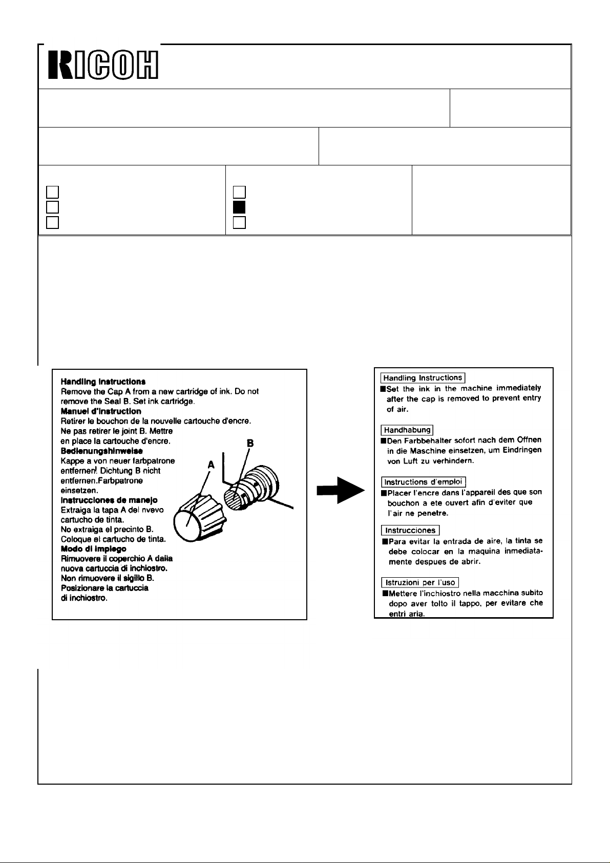
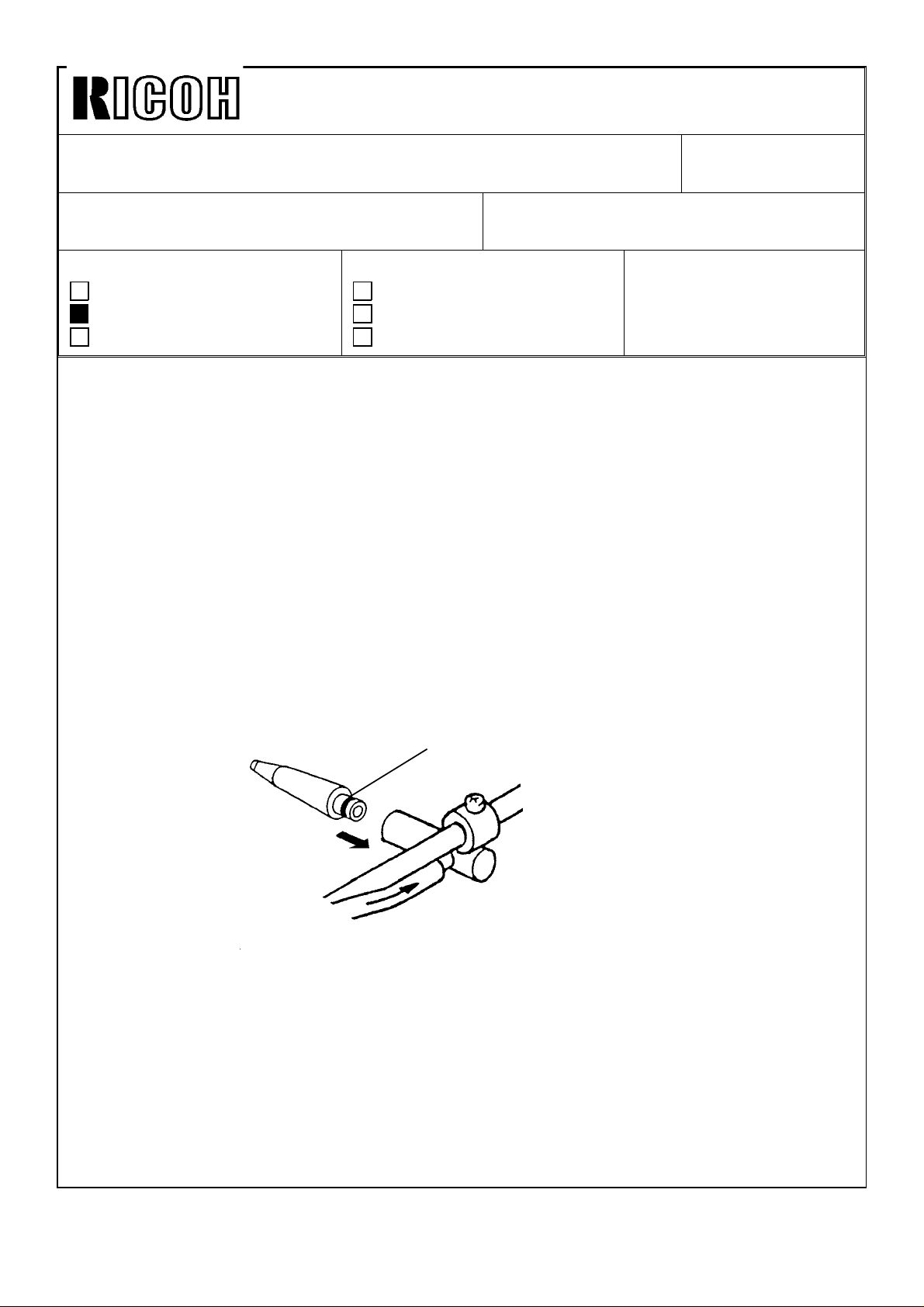
To increase ink production, the transparent seal will be removed from the exit of the black
ink cartridge (500cc and 800cc ink). For the color inks, the transparent seal remains
because the color inks are more fluid than the black ink.
Due to this change, the instructions printed on the black ink cartridge will be changed as
shown below.
OLD
Revision of service manual
Information only
Other
FROM: Copier Technical Support Section
MODEL:
VT3500
Ges 5375/Rex 1280
NSA CP375
NEW
This modification will be implemented from the October ’91 production run for the 500cc
ink cartridge and November ’91 production run for 800cc ink cartridge.
Page 2

Technical Bulletin No. RTB-000
SUBJECT: DATE:
PAGE: 2 of
Page 3

Technical Bulletin No. RTB-002
SUBJECT: ROM Change
( B jam with A4/LT drum/Jam detection in Skip Feed mode )
PREPARED BY: S. Asai
CHECKED BY:
CLASSIFICATION:
Action Required
Troubleshooting
Retrofit Information
[ Contents of ROM Modification ]:
The ROM on the main control board has been modified due to the following reasons:
Reason 1:
There has been reports in the field of the B jam with the A4/LT optional drum because the
paper feed solenoid does not turn on at correct timing. This problem only occurs in proof
mode (trial print) when the optional A4/LT drum is installed. Therefore, when the proof
print number is set to zero with SP mode 81, the problem ( B jam ) disappears. Please
note that this problem does not happen very often. One circumstance when this occurs is
when the drum rotation is delayed due to an overload.
Revision of service manual
Information only
Other
FROM: Copier Technical Support Section
MODEL:
VT3500
Ges 5375/Rex 1280
NSA CP375
DATE: Nov.15,’91
PAGE: 1 of 5
On the A3 drum, the paper feed solenoid turns on when the master making process is
completed. However, this ON timing is too early for the A4/LT drum. Therefore, on the
A4/LT drum. the paper feed solenoid turns on when the 2nd drum position sensor turns
on.( Normally, the 2nd drum position sensor turns on while the cutter returns to the home
position. Then, the process proceeds to the master wrapping process.) But, if the drum
rotation is delayed due to an overload, a paper jam is detected during the master
wrapping process because the 2nd drum position sensor ON timing is delayed. Normally,
the 2nd drum position sensor should be OFF at this time. (See the attached flow chart A.)
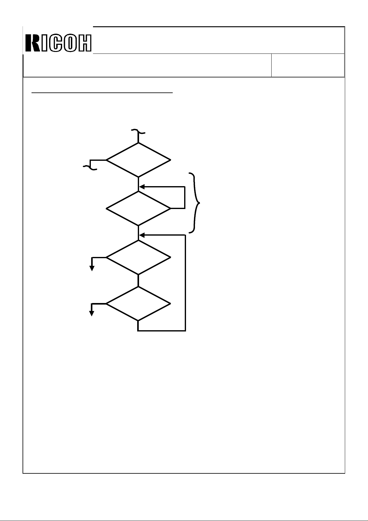
To prevent the above problem, the ROM program relating to the master wrapping process
has been modified. During master wrapping process, the paper misfeed is detected after
the 2nd drum position sensor turns off. (See the attached flow chart B.)
Page 4
Technical Bulletin No. RTB-002
SUBJECT: ROM Change DATE: Nov.15,’91
PAGE: 2 of 5
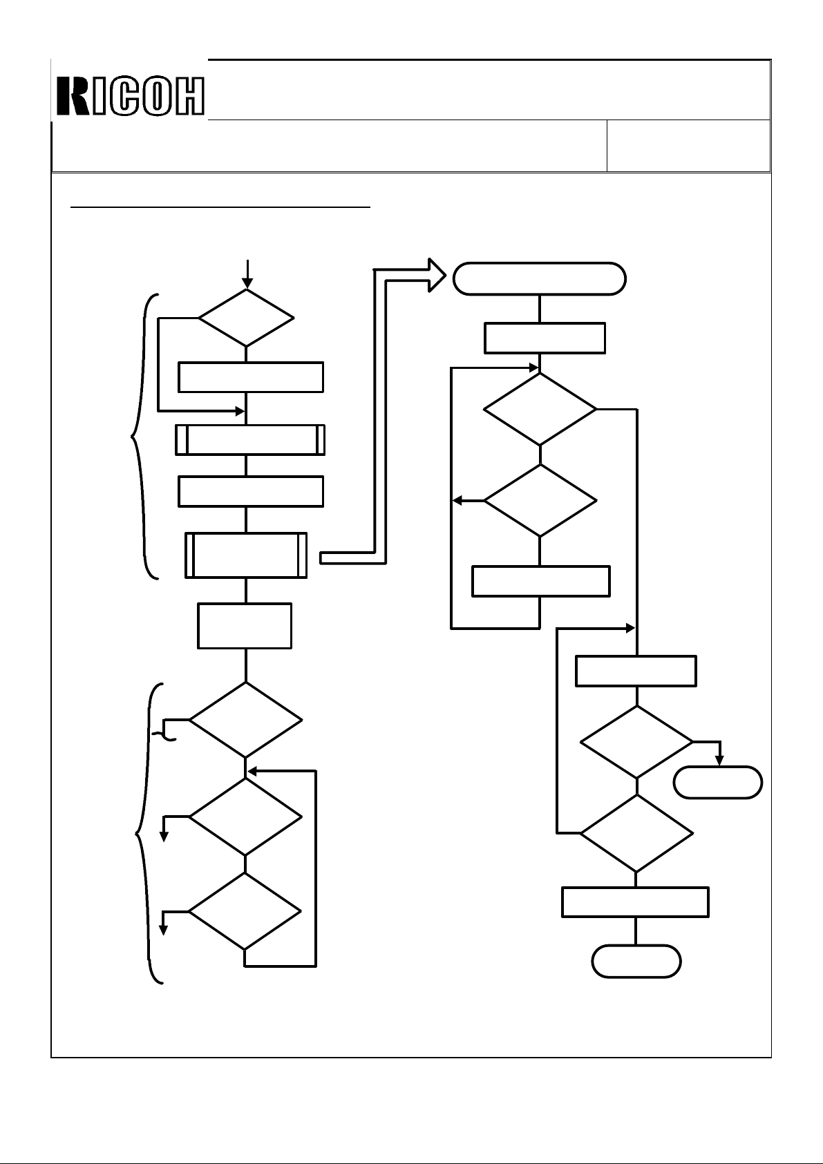
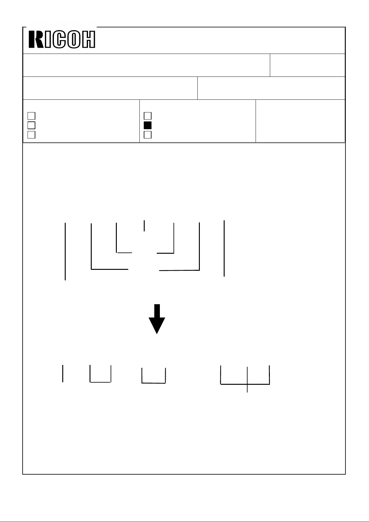
Current ROM Program (Flow Chart A)
Master Making Process is completed
Cutter Return Process
Master
Cut
Process
Yes
A4 Drum
?
No
Paper Feed SOL ON
Cutter ON Process
Drum starts rotating
Cutter Return
Process
Master is fed
40 mm
Cutter Motor ON
Front Cutter
SW ON ?
No
No
2nd Drum
Position SN
ON ?
Yes
Paper Feed SOL ON
Yes
Cutter Motor OFF
Master
Wrapping
Process
Yes
Yes
OK
Yes
B Jam
Proof Print
No. "0" ?
No
Printing
Pressure
ON ?
No
2nd Drum
Position SN
ON ?
No
Paper Feed
SOL ON ?
No
No
2nd Drum
Position SN
ON ?
Yes
Paper Feed SOL ON
Return
Yes
Return
Page 5
Technical Bulletin No. RTB-002
SUBJECT: ROM Change DATE: Nov.15,’91
PAGE: 3 of 5
Modified ROM Program ( Flow Chart B)
Master Wrapping Process
Yes
Yes
OK
Yes
B Jam
Proof Print
No. "0" ?
No
2nd Drum
Position SN
OFF ?
Yes
Printing
Pressure
ON ?
No
2nd Drum
Position SN
ON ?
No
No
Additional Flow (Program)
Page 6
Technical Bulletin No. RTB-002
SUBJECT: ROM Change DATE: Nov.15,’91
PAGE: 4 of 5
Reason 2:
In order to enable a long sheet paper feeding (more than A3/DLT size) without misfeed
detection, an additional subroutine has been added to SP 82 (Skip Feed mode) as follows:
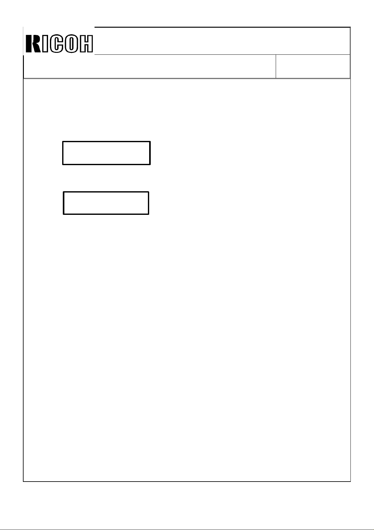
When SP 82 is selected, LCD is displayed as follows:
Skip Feed No.
1- 1 - 5 1
If 2 or more is set as a Skip Feed No. and then the Enter key is pressed, the following
LCD is displayed. The additional routine asks if the sheets used are longer than A3 or DLT
size.
Long Sheet ?
0: No 1: Yes 0
On the above display, if "0"(No) is selected, paper feed detection is normal mode.
However, if "1"(Yes) is selected, ignore the paper exit jam detection so that a long sheet
paper can be fed without misfeed detection.
Note: 1. The Maximum length of a long sheet paper is 600 mm.
2. The A4 optional drum cannot be used with this new mode (long sheet paper
feeding).
3. When the paper length is 450 or more, printing sheet may be stained by the
master trailing edge. Also, when the paper length is 477 or more, printing sheet
may be stained by the rubber pads used for turning the pressure roller.
4. Pull the paper delivery end plate down if the paper length is long. Hold the
printing sheets delivered from the machine. Otherwise, printing sheets drop from
the paper delivery table.
[P/N and S/N Information]:
The ROM part number for each language remains the same. However, a suffix (9th
character) has been changed as follows:
Old P/N New P/N
C2108626A C2108626B (Europe version in English) Total Sum Check "0100"
C2108452 C2108452A (Europe version in French) Total Sum Check "2800"
C2108457 C2108457A (Europe version in Italian) Total Sum Check "2A00"
C2108455 C2108455A (Europe version in Spanish) Total Sum Check "0700"
C2108450 C2108450A (Europe version in German) Total Sum Check "0D00"
C2108621A C2108621B (American version in English) Total Sum Check "0600"
C2108459 C2108459A (American version in French) Total Sum Check "2D00"
C2108461 C2108461A (American version in Spanish) Total Sum Check "0C00"
Page 7

Technical Bulletin No. RTB-002
SUBJECT: ROM Change DATE: Nov.15,’91
PAGE: 5 of 5
The new ROM has been implemented since the October ’91 production. The cut-in serial
numbers are as follows:
Ges 5375 (NA version): S/N 50621100001Ges 5375 (Eu version): S/N 50611100001Rex 1280: S/N 50611100141NSA CP375: S/N 50611100161-
VT3500: S/N C2791100001Note: On the VT3500 (S/N C279110****) produced in October ’91, the new ROM has
not been implemented on machines with serial numbers (last 4 digits) listed below:
0031, 0048, 0050, 0096, 0105, 0106, and 0108.
Page 8
Technical Bulletin No. RTB-003
SUBJECT: Paper Exit Pawl DATE: Feb. 15, ’92
PAGE: 1 of 1
PREPARED BY: S. Asai
CHECKED BY:
CLASSIFICATION:
Action Required
Troubleshooting
Retrofit Information
[Phenomenon]:
During the printing run, the paper exit pawl slightly comes off and it contacts the drum
screen. This causes a black line on copies. In the worst case, the exit pawl contacts the
master clamper and the clamper may be damaged.
[Countermeasure]:
1. Check whether the exit pawl comes off or not.
2. Make sure that the exit pawl does not come off by pulling it out with light force ( with
fingers).
3. If it comes off, apply super glue one turn around the joint area and insert it as shown.
Note: Before applying super glue, place a sheet of paper on the vacuum unit to prevent
glue from dropping on the vacuum belt.
Revision of service manual
Information only
Other
FROM: Copier Technical Support Section
MODEL:
VT3500
Ges 5375/Rex 1280
NSA CP375
Super Glue
[Causes]:
Variation of amount of glue
The amount of glue has been controlled since December ’91 production. The cut-in serial
number for each model is as follows:
VT3500: S/N C2791120001-
Ges5375/Rex 1280/NSA CP305: USA version: S/N 50621120001-
Europe/Asia version: S/N 50611120001 Taiwan version: S/N 50631120001-
Page 9
Technical Bulletin No. RTB-004
SUBJECT: Pressure On/Off Lever Breakage DATE: June 15, ’92
PAGE: 1 of 1
PREPARED BY: H. Kokubo
CHECKED BY:
CLASSIFICATION:
Action Required
Troubleshooting
Retrofit Information
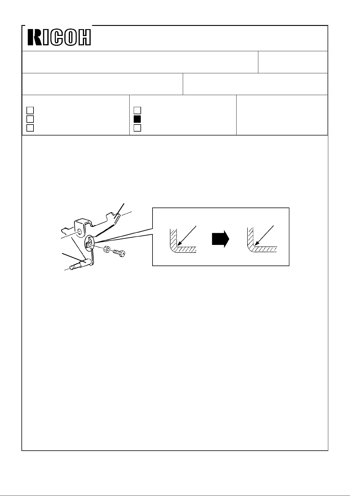
It was reported that the adjusting screw tab of the pressure on/off lever is sometimes
broken.
The pressure on/off lever (part number: C200 5566) is commonly used for all the series
models, but this problem is typical only on this model. This is because the pressure
roller’s pressure of this model is higher than that of the other models due to the A3 size
printing.
C2005566: Pressure On/Off Lever
Shaft
Revision of service manual
Information only
Other
FROM: Copier Technical Support Section
MODEL:
VT3500
Ges 5375/Rex 1280
NSA CP375
R0.5
R2
To increase the durability of the lever, the angle has been rounded as shown in the
illustration. This will reduce the stress on the adjusting screw tab. The new type lever has
been applied since the May ’92 production. The cut-in serial numbers are as follows:
C210-12 (Ges 115V version): 50622050001
C210-13 (Ges TWN version): From next production
C210-14 (Rex TWN version); From next production
C210-15 (Rex 115V version): From next production
C210-16 (NSA 115V version): From next production
C210-19 (Ricoh TWN version):From next production
C210-22 (Ges Eu. version): 50612050001
C210-24 (Rex Eu. version): 50612050217
C210-25 (NSA Eu. version): 50612050274
C210-27 (Ricoh Eu. version): C2792050001
C201-29 (Ricoh 220V version):C2792050201
The new lever has also been applied for all the other series models from May ’92
production due to part standardization.
Note: Although the part number (C200 5566) is still the same, the shaft on the lever is
marked with white paint. All spare parts which have been delivered from our SPC
since May ’92 are the new type only. Please note that the old type lever can still
be used for the other series models.
Page 10
Technical Bulletin No. RTB-005
SUBJECT: Priport Ink Lot Number DATE: Aug. 15, ’92
PAGE: 1 of 2
PREPARED BY: J. Mochizuki
CHECKED BY:
CLASSIFICATION:
Action Required
Troubleshooting
Retrofit Information
To clarify the ink production dating, the method of lot numbering has been changed as
follows:
Revision of service manual
Information only
Other
FROM: Copier Technical Support Section
MODEL:
VT3500
Ges 5375/Rex1280
NSA CP375
Old method
.
1912762
Year
Date
Month
Internal use only
Internal use only
New method
20617–121
Year Month
The above lot number means that the ink is produced on June 17, ’92
Date
Internal use only
Page 11
Technical Bulletin No. RTB-005
SUBJECT: Priport Ink Lot Number DATE: Aug. 15, ’92
PAGE: 2 of 2
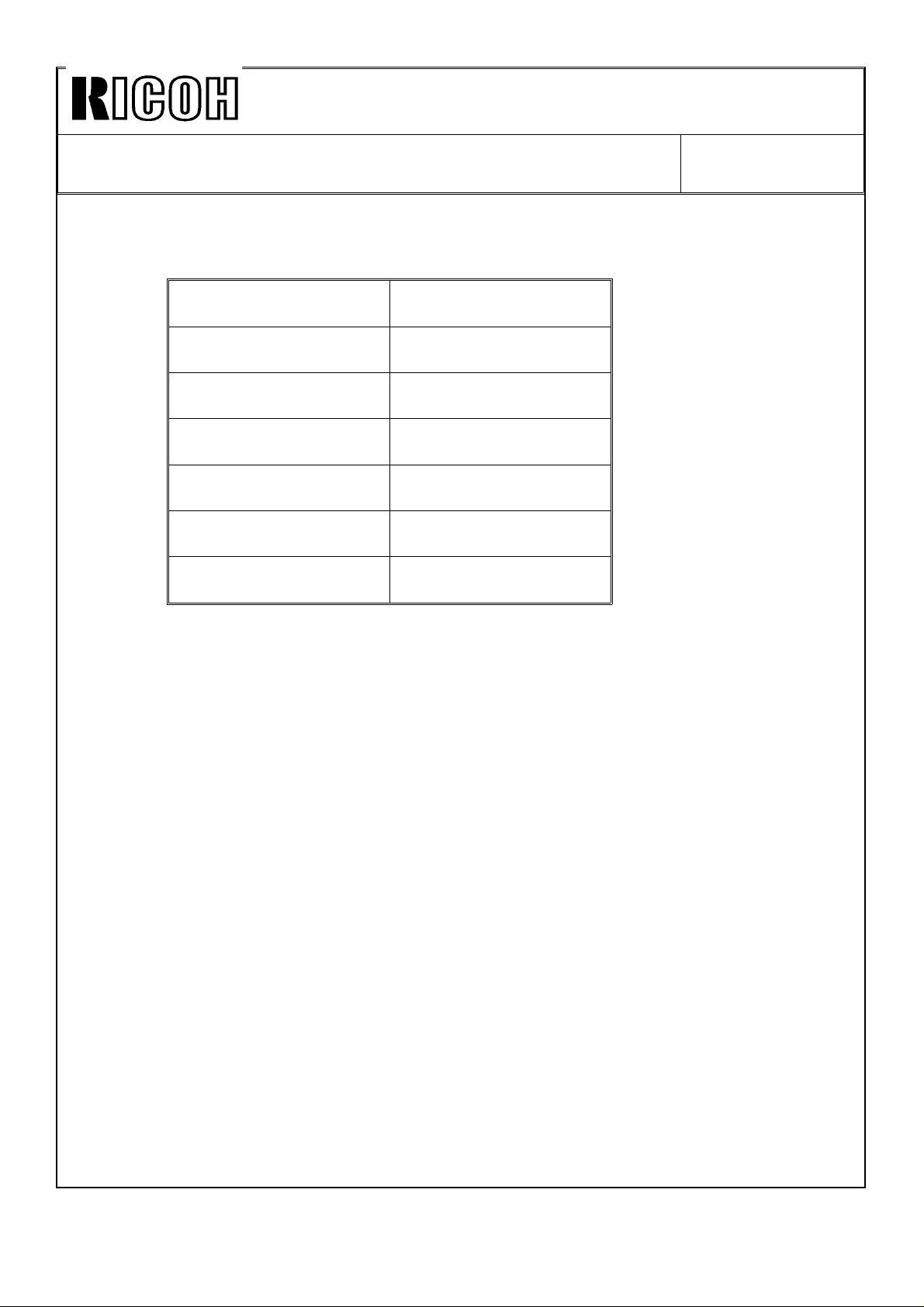
The table below shows the new lot numbering start date.
Type of ink New lot numbering
start date
Black 800cc July 13, ’92
Black 500cc July 13, ’92
Color Red 500cc July 13, ’92
Color Blue 500cc July 16, ’92
Color Green 500cc J uly 14, ’92
Color Brown 500cc July 16, ’92
Page 12
NmmMl
Technical Bulletin
No.
RTB-006
SUBJECT: Damage of Optional A4 Drum
PREPARED BY: H.
CHECKED BY:
CLASSIFICATION:
■ Action Required
❑ Troubleshooting
❑ Retrofit Information
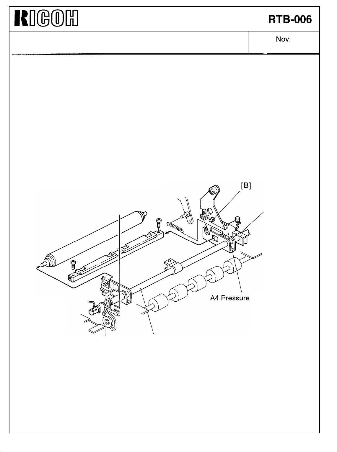
When the optional A4 drum is used, the pressure of the press roller is released from the
drum by the cam installed in the drum itself, unlike the A3 drum, which is originally
installed in the machine. The cam applies strong force to the A4 pressure on/off lever that
is connected with the press roller shaft in order to drive it and release the press roller
pressure,
It was reported that the bolt (M5x14 hexagonal hole head bolt) that secures the A4
pressure on/off lever on the press roller shaft breaks. This will cause the exit
the drum surface because the exit
Kokubo
❑ Revision of service manual
❑ Information only
❑ Other
pawl
drive cam is fixed with the A4 pressure on/off lever.
FROM: Copier Technical Support Section
MODEL:
Priport
Ges 5375/Rex 1280/
Nsa
DATE:
PAGE: 1 of 2
VT3500/
CP375
.
pawl
NOV.
to hit
30, ’92
Since August 1992, the torque to tighten the bolt has been reduced and controlled to 40
to 50
there was possibility of the bolt breaking while using the optional A4 drum. The cut-in
serial numbers are as follows:
C210-12 (Ges U.S.A.): 50622080001
C210-13 (Ges Taiwan): 50632080001
C210-22 (Ges Europe): 50612090001
C210-24 (Rex Europe): 50612080001
C210-25 (Nsa Europe): 50612080016
C210-27
C210-29
Note:
kgfcm
on the production line. In the past, it was around 100
(Ricoh
(Ricoh Asia, etc.): C2792080108
Even if the bolt is tightened manually with a hexagon key, if a engineer tightens as
much as he can, the torque will be about 70
Europe): C2792080001
kgfcm.
kgfcm.
It was found that
Page 13
WImMl
Technical Bulletin
No.
RTB-006
SUBJECT: Damage of Optional A4 Drum
[Action Required]
When the optional A4 drum is installed for a machine produced before the cut-in serial
numbers listed in the preceding page, perform the following:
1. Replace the bolt [A] with a new one (P/N: 05950140E).
2. Be sure that the bolt [B] (M4x6 hexagonal hole head bolt) is firmly tightened. If this is
loose, the A4 pressure on/off lever does not operate properly.
DATE:
PAGE: 2 of 2
.
[A]
NOV.
30, ’92
ON/OFF Lever
II
Press Roller Shaft
Page 14

WImMl
Technical Bulletin No. RTB-007
SUBJECT: A4 Pressure On/Off Lever Damage
PREPARED BY: H. Kokubo
CHECKED BY:
CLASSIFICATION:
❑
Action Required
■
Troubleshooting
❑
Retrofit Information
It was reported that the bolt (P/N: 05950140E) securing the A4 pressure on/off lever
sometimes breaks (see RTB
At worst, you may have to replace the A4 pressure on/off lever together with the press
roller shaft if the head of the bolt is broken and the lever cannot be removed from the
press roller shaft.
To cope with such situation, we have registered the press roller shaft kit (P/N: C210
9505)
as a service part. (See page 8 of 9.) This bulletin is to give the installation procedure
for the kit.
/W%e
no.
❑
Revision of service manual Priport
❑
Information only
❑
Other
6).
FROM: Copier Technical Support Section
MODEL:
Ges 5375/Rex 1280/
Nsa CP375
DATE:
PAGE: 1 of 9
.
VT3500/
NOV.
30, ’92
Follow the procedure below only when you cannot remove the broken bolt from the
press roller shaft and you have to replace the press roller shaft with new one.
1. Make sure that the paper feed table is in its lowest position and the drum is in its home
position, Then, turn off the main switch and disconnect the power cord.
2. Remove the front and rear covers.
3. Remove the drum unit.
4.
Remove the plotter unit. (Refer to page 5-18 in the service manual.)
5. Remove the A3 printing pressure cam. (Refer to page 5-69 in the service manual.)
(Continued)
Page 15
Km(ml
Technical Bulletin
No.
RTB-007
SUBJECT: A4 Pressure On/Off Lever Damage
[D] —__
DATE:
PAGE: 2 of 9
.
A]
NOV.
30, ’92
/
[c]
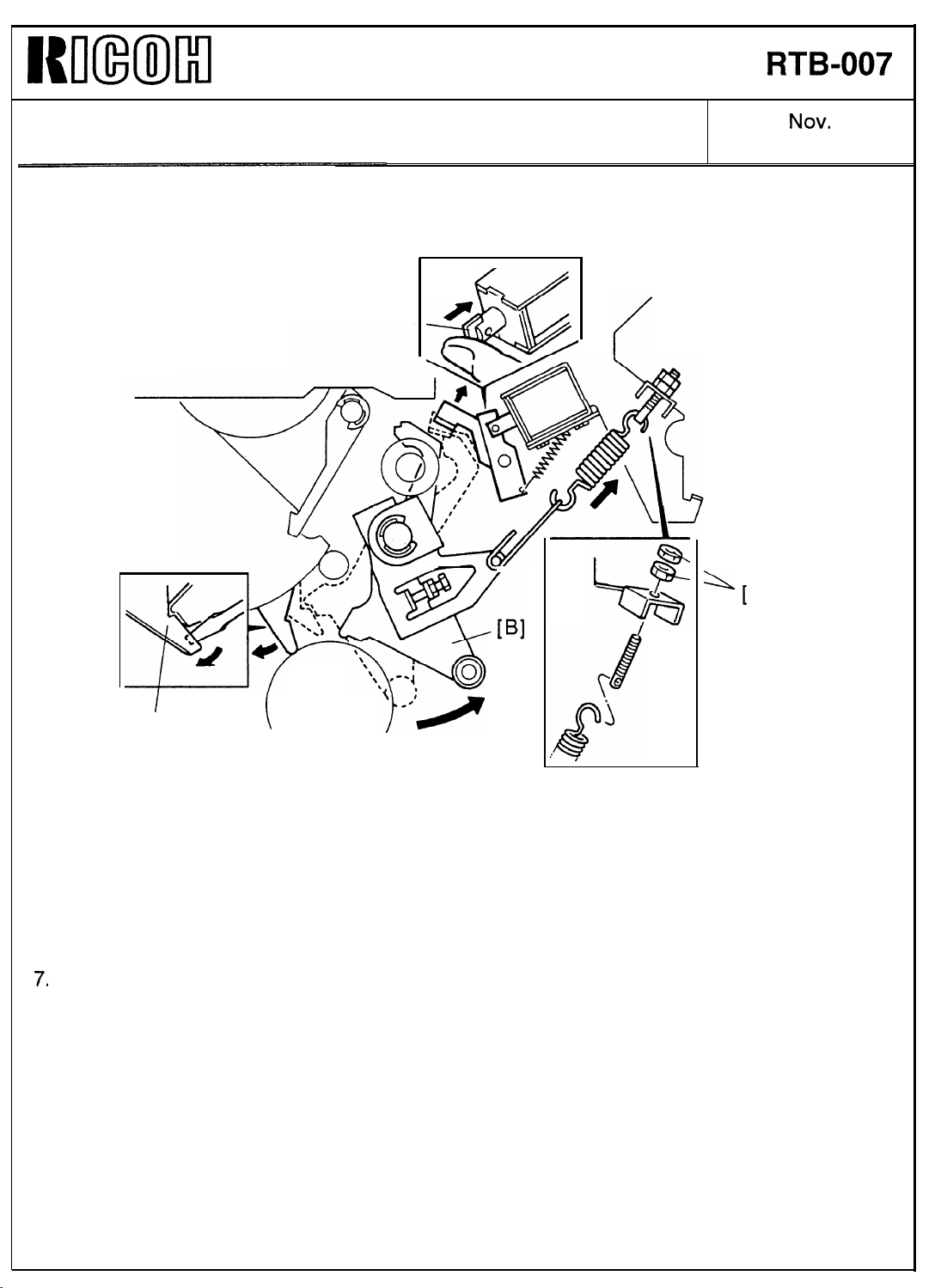
6. While pressing the plunger of the pressure release solenoid [D], disengage the paper
detection arm [C] from the A3 pressure on/off lever [B]. Using a spanner, turn the drum
shaft manually until the printing pressure is applied.
7.
While the printing pressure is applied, remove the printing pressure spring by loosening
the two nuts [A].
(Continued)
Page 16

Kmml
Technical Bulletin
No.
RTB-007
SUBJECT: A4 Pressure On/Off Lever Damage
B
DATE:
PAGE: 3 of 9
NOV.
30, ’92
8.
Note: The lever and arm are securely held on the shaft with a spring pin [A]. Before pull
(Continued)
the A3 pressure on/off lever [B] with the pressure spring arm [C] as shown.
them out of the shaft, apply a sufficient amount of spray grease or equivalent.
After that, insert two screwdrivers behind the pressure on/off lever and gradually
moves the screwdrivers to take the lever and arm out the spring pin. Finally, pull
them out using pliers.
Page 17

I{lnmm
Technical Bulletin
No.
RTB-007
SUBJECT: A4 Pressure On/Off Lever Damage
DATE:
PAGE: 4 of 9
NOV.
30, ’92
.
—
[D]
9. Remove the upper second feed roller [B] (2 springs), then remove the upper and lower
paper guide plates [C] (2 screws),
Note:
10.
(Continued)
* You do not have to remove the upper second feed roller completely to remove
the paper guide plates.
* When reassembling the paper guide plates, make sure that the guide plates do
not touch the lower second feed roller,
Remove the sensor actuator [A] on the front of the press roller shaft (1 screw), and
remove an E-ring and the bushing [D].
[c]
Page 18

WmMl
Technical Bulletin
No. RTB-007
SUBJECT: A4 Pressure On/Off Lever Damage
DATE:
PAGE: 5 of 9
Nov.
30, ’92
.
11. Remove the press roller [B] and press roller guide [A] (2 screws).
12. Remove the spring [C].
(Continued)
Page 19

I{u(IixmI
Technical Bulletin
No. RTB-O07
SUBJECT: A4 Pressure On/Off Lever Damage
[B]
II
DATE:
PAGE: 6 of 9
[B]
NOV.
30, ’92
13. Slide the A4 pressure on/off lever to the front, so that you can remove the press roller
shaft.
If the head of the bolt breaks and you cannot slide the A4 pressure on/off lever to
the front, follow the steps below:
1)
Remove the A4 cam follower bracket [A] (1 bolt).
2) Bend the A4 pressure on/off lever [B] as shown using pliers. Grasp the front end of
the press roller shaft and bend it more by pressing the lever against the rear frame.
(Continued)
Page 20

MmmIl
SUBJECT: A4 Pressure On/Off Lever Damage
Technical Bulletin
No. RTB-007
NOV.
DATE:
PAGE: 7 of 9
.
30, ’92
3) Remove the press roller shaft through the cutout of the rear frame as shown.
(Continued)
Page 21

NmmIKl
Technical Bulletin
No.
RTB-007
SUBJECT: A4 Pressure On/Off Lever Damage
[G]
DATE:
PAGE: 8 of 9
NOV.
30, ’92
.
[F]
[E]
14. Remove all parts from the press roller shaft. Then, replace the defective parts with new
ones. If you use the press roller shaft kit (see Note below), remove the front press
roller arm [A] and two bolts with the nuts [G] from the old press roller shaft, and add
them to the kit.
Note: To replace the A4 pressure on/off lever, you have to remove the spring pin [F] on
the rear of the press roller shaft. However, It is difficult to remove it because the
spring pin is firmly fitted in the hole of the shaft. Also, it may be difficult to remove
the bolt from the shaft if it has broken.
To cope with such a situation, we have registered the press roller shaft kit (P/N:
C210 9505)
parts (not assembled). Please order it from our SPC as usual.
* Press roller shaft
* Rear press roller arm (C2095553) [C]
* A4 pressure on/off lever
* Exit pawl drive cam
* Bushing
* Spring pin - 4x22 (08044060) [F]
* Hexagon bolt - M5x14 (05950140E)
(Continued)
as a service part. The kit is composed of one each of the following
(C2095505)
(C2036004) [D]
(C2005526) [E]
[B]
(C2095570) [H]
Page 22

Iwlmmil
Technical Bulletin
No.
RTB-007
SUBJECT: A4 Pressure On/Off Lever Damage
[B]
DATE:
PAGE: 9 of 9
NOV. 30, ’92
15. Assemble the press roller shaft and install it in the machine,
Note: *
16.
Reassemble all the removed parts.
Check the following:
17.
* Press roller position (Page 5-50 and 5-51 in the service manual)
* Printing pressure timing (Page 5-52)
* Printing pressure (Page 5-53)
* Clearance of exit
* Exit pawl timing (Page 5-76)
Do not secure the A4 pressure on/off lever first. Slide the A4 pressure on/off lever
to the front when you install the press roller shaft. Then, slide-it to the rear and
secure with the bolt [A].
* Position the spring pin [B] in the hole of the press roller shaft so that the A3
pressure on/off lever and pressure spring arm can be installed,
pawl
(Page 5-75)
Page 23

Technical Bulletin No. RTB-008
SUBJECT: Ink Set-off on Prints or Master Damage When Using the
VT-II Master
PREPARED BY: H. Kokubo
CHECKED BY: S. Hamano
CLASSIFICATION:
Action Required
Troubleshooting
Retrofit Information
There are two types of the master for the NA2. They are the VT-II master (RICOH VT-II-L,
NRG CPMT10, ABDICK 60-6725) and VT master (RICOH VT-L, NRG CPMT6, no
equivalent for ABDICK). The VT-II master is slightly more sensitive to the heat of the
thermal head than the old VT master. (The VT-II master has started being used instead of
the old VT master.) When the VT-II master is used, the following symptom might occur:
Revision of service manual
Information only
Other
FROM: 2nd Technical Support Section
MODEL: Priport NA2
(Ricoh VT3500/
Ges 5375/Rex 1280/
Nsa CP375/ABDICK 6720)
DATE: Dec. 15, ’94
PAGE: 1 of 2
SYMPTOM
- Amount of ink transferred on prints increases due to larger holes made by the thermal
head on the master than those of the old VT master. As a result, ink set-off on the
reverse side of prints will increase.
- The thermal head makes too large holes on the master and some parts of the
master surface (the polyester film layer) are peeled off during printing. The damaged
parts will appear as black patches on prints.
SOLUTION
Reduce the thermal head energy using the SP mode as follows:
1. Access the SP mode. (Press the Clear Modes key, Clear key, Combine 2 Originals key,
then Enter (#) key in this order.)
2. Select SP 35 "Head Energy Adjust." (Input "35", then press Enter key.)
3. Input "15", then press Enter key to set it at -15%. (The default setting is -5%.)
4. Press the Clear Modes key to leave the SP mode.
NOTE:
1) The thermal head energy can also be reduced by reducing the input voltage with the
potentiometer in the power supply unit (see service manual page 5-17 "ADJUSTING
THE THERMAL HEAD VOLTAGE"). However, this is not effective against the above
symptom and the above solution must be used. SP 35 enables the adjustment of the
pulse length which determines the period that voltage is applied to the thermal head.
Page 24

Technical Bulletin No. RTB-008
SUBJECT: Ink Set-off on Prints or Master Damage When Using the
VT-II Master
2) If you also reduce the press roller pressure (the printing pressure) to reduce the ink
set-off, turn the adjusting bolt until the clearance becomes 8 mm. (See service manual
page 5-53 "ADJUSTING THE PRINTING PRESSURE." The standard setting for the
clearance is 4 mm.) However, this will give just a little improvement against the ink
set-off and the following side effects are expected:
- Since the ink is not transferred quickly enough from the ink roller to paper at the
beginning of a printing run, images with insufficient ink will appear on the first few
prints.
- The image density will be slightly lighter.
- When printing is made on A3 or 11" x 17" (the full size) paper, images on both edges
might become faint because of insufficient printing pressure.
3) When you reduce the thermal head energy with the SP mode, tiny white spots tend to
be more visible in solid-fill image areas. This is just like the images made with the old
VT master. The density of the solid-fill images looks slightly lighter. (Therefore, you
should not reduce the thermal head energy more than -15% as indicated in the above
procedure.) You can reduce the tiny white spots if the 2 thermal head springs
(P/N-C209 4033) and the platen roller (P/N-C209 4047) are replaced with those for the
NA3 model (RICOH VT3600, Gestetner 5380, RexRotary 1285, nashuatec CP380,
ABDICK 6770).
DATE: Dec. 15, ’94
PAGE: 2 of 2
- Thermal Head Spring: P/N-C218 4034 (2 springs are needed.)
- Platen Roller: P/N-C218 4045
These parts can apply more platen roller pressure against the master during master
making and improve the tiny white spots in solid-fill images.
4) If the fences on the paper delivery table are not adjusted exactly to the paper size, ink
set-off on the reverse side of prints will increase. Instruct the operator if he is not
familiar with this.
Page 25

Technical Bulletin No. RTB-009
SUBJECT: Ink Pump Improvement (For the NA2/NA3/NB2 Only) DATE: Nov. 15, ’95
PAGE: 1 of 2
PREPARED BY: H. Kokubo
CHECKED BY:
CLASSIFICATION:
Action Required
Troubleshooting
Retrofit Information
NA2: Ricoh VT3500/Gestetner 5375/RexRotary 1280/nashuatec CP375/ABDICK 6720
NA3: Ricoh VT3600/Gestetner 5380/RexRotary 1285/nashuatec CP380/ABDICK 6770
NB2: Ricoh VT2600/VT2630/Gestetner 5360/RexRotary 1270/nashuatec CP360
RN925: Ricoh VT2400/Gestetner 5340/RexRotary 1255/nashuatec CP340/ABDICK 6550
Information for the NA3/NB2/RN925 starts from this bulletin. RTB numbers 1 to 8
are for the NA2 only.
To ensure that all ink in the cartridge is supplied,
a spring has been added inside the ink
pump as shown to the right. The spring
ensures that the small ball, which is used as a
valve, is pushed back properly.
Revision of service manual
Information only
Other
FROM: 2nd Technical Support Section
MODEL:
Priport
NA2/NA3/NB2/RN925
This modification has been applied from the
September 1995 production runs of all
Priport series. The part numbers of
the ink pump assemblies remain the same.
(Note that the N850 and RN925 have been
using the new type from the first mass
production.)
There are three types of ink pump. They
are the NA/NB type that can hold the
1000 cc ink cartridge, the N type that can
hold the 600 cc ink cartridge only, and the
N810 type that is for the N810 and N810-II
only. See the following table for the
applicable models.
TYPE OF
INK PUMP
NA/NB NA-2, NA-3, NB-2
N N865, N860, N915, N935, N955, and all SS series models.
N810 N810, N810-II
APPLICABLE MODELS
Packing
Valve
Newly Added
Spring
Socket
[Section Plan of the Bottom Part
of the Ink Pump]
Page 26

Technical Bulletin No. RTB-009
SUBJECT: Ink Pump Improvement (For the NA2/NA3/NB2 Only) DATE: Nov. 15, ’95
PAGE: 2 of 2
There are two types of spring for these three types of the ink pump. The part numbers are:
C222 4710 (Pump Spring - 21 mm) : For the NA/NB type ink pump.
C224 4715 (Pump Spring - 13 mm) : For the N and N810 type ink pumps.
SOLUTION IN THE FIELD
For the field machines, you can install the spring after removing the socket (with two
screws). (It takes longer to replace the whole pump assembly.)
CAUTION: When you remove the socket, ink will leak. Be sure to place absorbent
material to prevent ink from getting on the floor.
NOTE: 1. There is a packing between the socket and housing (see the illustration on the
previous page). If it is damaged, you may have to replace the packing at the same
time. (Normally, this is not required.) The part number is:
C200 4827 (Packing - Pump Socket)
2. A rubber packing is used as shown below in order to ensure that the nozzle of
the ink cartridge tightly contacts the pump socket. Check if this part is dislocated.
The rubber packing used in the N810, the N865, and the other later models is
adhered with glue, but it is not adhered for the other older models.
C200 4826
(Pump Rubber)
Page 27

Technical Bulletin No. RTB-010
SUBJECT: Master Eject Belt Modification DATE: Mar. 31, ’96
PAGE: 1 of 2
PREPARED BY: H. Kokubo
CHECKED BY: M. Iwasa
CLASSIFICATION:
Action Required
Troubleshooting
Retrofit Information
NA2: Ricoh VT3500/Gestetner 5375/RexRotary 1280/nashuatec CP375/ABDICK 6720
NA3: Ricoh VT3600/Gestetner 5380/RexRotary 1285/nashuatec CP380/ABDICK 6770
NB2: Ricoh VT2600/VT2630/Gestetner 5360/RexRotary 1270/nashuatec CP360
RN925: Ricoh VT2400/Gestetner 5340/RexRotary 1255/nashuatec CP340/ABDICK 6550
Revision of service manual
Information only
Other
FROM: Technical Support Section
MODEL:
Priport
NA2/NA3/NB2/RN925
PROBLEM
Master eject jams frequently occur. In the worst case, the upper or lower master eject belts
slip off the rollers.
CAUSE
At the March 1995 production of all PRIPORT models, the vendor who produced the upper
and lower master eject belts was changed. (The part numbers were not changed because
there was no change in configuration.) Since then, all PRIPORT models have been using
the belts manufactured by the new vendor.
Recently it was found that some of these parts tend to stretch and can cause the problem,
as stated above, due to part variation. (The occurrence of the problem varies from one lot
to another.)
Page 28

Technical Bulletin No. RTB-010
SUBJECT: Master Eject Belt Modification DATE: Mar. 31, ’96
PAGE: 2 of 2
SOLUTION
The upper and lower master eject belts will be modified as follows:
Inter-
Old P/N New P/N Description Q’ty used
C219 3545 C219 3605 Upper Belt
C219 3546 C219 3606 Lower Belt
4 → 4
* (5 → 5)
4 → 4
* (5 → 5)
changeability
x/o
x/o
Applicable Models
NB2, N850, RN925, NA33
* : The number of both
parts used for the NA33
is 5.
C200 3545 C219 3605 Upper Belt
C200 3546 C219 3606 Lower Belt
NOTE: There are two types of old part numbers as shown in the table. Both these types
will be changed into a new type of upper and lower belt.
The new upper and lower belts will be implemented into the production from April 1996.
For the service parts, the SPC will have the new parts in stock soon.
4 → 4
* (5 → 5)
4 → 4
* (5 → 5)
x/o
x/o
NA3, NA2, N865, and
other older models.
* : The number of both
parts used for the NA3
and NA2 is 5.
Page 29

Technical Bulletin No. RTB-011
SUBJECT: Worn Main Drive Gear (NA3/NB2 Only) DATE: June 15, ’96
PAGE: 1 of 2
PREPARED BY: H. Kokubo FROM: Priport Service Planning Section
CLASSIFICATION:
Action Required
Troubleshooting
Retrofit Information
NA2: Ricoh VT3500/Gestetner 5375/RexRotary 1280/nashuatec CP375/ABDICK 6720
NA3: Ricoh VT3600/Gestetner 5380/RexRotary 1285/nashuatec CP380/ABDICK 6770
NA33: Ricoh VT3800/Gestetner 5385/RexRotary 1290/nashuatec CP385/ABDICK 6790
NB2: Ricoh VT2600/VT2630/Gestetner 5360/RexRotary 1270/nashuatec CP360
RN925: Ricoh VT2400/Gestetner 5340/RexRotary 1255/nashuatec CP340/ABDICK 6550
Information for the NA33 starts from this bulletin. RTBs 1 to 10 are for the
NA2/NA3/NB2/RN925 only.
It was found that gears C2032215 and C2032326 (see the illustration on the next page)
can rapidly wear out if they are not greased. In particular, gear C2032215 wears out faster
(after abo ut 30,000 to 50,0 00 copies) .
Revision of service manual
Information only
Other
MODEL:
Priport
NA2/NA3/NA33/
NB2/RN925
It was also found on the production lines that some machines which were manufactured
during the period from the end of 1994 to May 1995 have a lack of greasing for these
gears. From April 1995, an inspection process was added to check the greasing of these
gears.
NOTE: The models NA2, RN925 and NA33 do not have this problem. The RN925 and NA33
started manufacture after May 1995, and there was no production of the NA2 during that
period. Therefore, it is only possible for the NA3 and NB2 to have this problem.
Page 30

Technical Bulletin No. RTB-011
SUBJECT: Worn Main Drive Gear (NA3/NB2 Only) DATE: June 15, ’96
PAGE: 2 of 2
RECOMMENDATIONS
Grease the gears (evenly on the surface of the gear C2032215) in the following cases:
1. For the machines detailed above (the NA3 and NB2 manufactured between the end
of 1994 and May 1995), check if grease is properly applied and grease if necessary.
2. Grease the gears every time when they are replaced.
3. Grease at yearly PM intervals (as mentioned in the service manual).
Gear: C203 2215
Gear: C203 2326
Page 31

PAGE: 1 OF 4
Technical Bulletin No. RTB-012
SUBJECT: New Paper Delivery Table ISSUED ON: July 15, 1996
CLASSIFICATION:
Action Required
Troubleshooting
Retrofit Information
Revision of service manual
Information only
Other
ISSUED BY:
H. Kokubo,
Priport Service Planning Section
MODEL: PRIPORT
NA2: Ricoh VT3500/Gestetner 5375/RexRotary 1280/nashuatec CP375/ABDICK 6720
NA3: Ricoh VT3600/Gestetner 5380/RexRotary 1285/nashuatec CP380/ABDICK 6770
NA33: Ricoh VT3800/Gestetner 5385/RexRotary 1290/nashuatec CP385/ABDICK 6790
NB2: Ricoh VT2600/VT2630/Gestetner 5360/RexRotary 1270/nashuatec CP360
RN925: Ricoh VT2400/Gestetner 5340/RexRotary 1255/nashuatec CP340/ABDICK 6550
This bulletin is to inform you that the new paper delivery table has been used from the
June 1996 production for the NB2, RN925, and NA33 models. (The NA2 and NA3 models
were discontinued. For the cut-in serial numbers, refer to the Modification Bulletins for
each model.)
The features of the new table are as follows:
Upper Guide Plate
Lower Guide Plate
1. Thanks to the newly added small guide plates on the upper of each front and rear side
fences, the copies are more evenly stacked on the table. Both edges of the copy are
guided by the small guide plates as the copy is fed out. Then, the copy is correctly
directed to the end plate for stacking.
------ Continued ----------------------------------------------------------------------------------------------------
Page 32

PAGE: 2 OF 4
Technical Bulletin No. RTB-012
The end plate is also new. The material and configuration of the cushion have been
changed. The new end plate better receives the copies for stacking. (The 2nd end
plate, which is for the smaller sized paper, remains the same.)
The other small guide plates, which are also provided on the bottom of each side
fence, can hold the copies in the center of the table while the copies are stacked on
the bottom.
This feature is more beneficial when thinner paper is used.
2. To prevent the side fences and end fence of the paper delivery table from being
pushed and spread outwards while the copies are stacked, the springs that hold those
fences straight-up have been strengthened. This also helps the copies to stack evenly.
REMARKS for using the new paper delivery table
1. It is recommended to use the upper small guide plates when thin or normal paper (80
g/m2 or 20 lbs and thinner paper) is used. For thicker paper, close the guide plates. If
paper is too thick, the paper tends to be caught by the upper guide plates. (Thick
paper can be stacked evenly even without using the upper guide plates.)
2. The paper stack capacity of the table reduces to around 750 sheets (this varies
depending on paper type) when the upper small guide plates are used. Close the
guide plates to achieve the maximum paper stack capacity.
3. When you store the paper delivery table, you must first close the upper small guide
plates.
4. The optional Tape Marker can be used for up to 500 sheets (this varies depending on
paper type). When the old paper delivery table is used, the Tape Marker’s capacity
was around 750 sheets. This is because the position of the Tape Marker has been
slightly lowered to prevent the dispensed tape from touching the added guide plate.
Tape Marker
Page 33

PAGE: 3 OF 4
Technical Bulletin No. RTB-012
5. Because of the new paper delivery table, the position of the Tape Marker has been
slightly lowered (as mentioned above). The tape marker bracket has been changed
from the June 1996 production of the Tape Marker as follows:
Q’ty
Old P/N New P/N Description
C532 2004 C532 2111 Tape Marker Bracket
To use the old type Tape Marker with the new paper delivery table, a new bracket is
necessary. The new bracket has an additional screw hole. Install the Tape Marker
using the holes [A] as shown below:
Used
1 → 1
Interchangeability
X/O 31-3
[A]
Location on
Parts Catalog
(Index-Page)
Page 34

PAGE: 4 OF 4
Technical Bulletin No. RTB-012
6. Since freshly printed sheets are stacked on the bottom of the delivery table, the ink on
the top copy of the stack tends to be transferred to the reverse side of the next fed-out
copy (this is called "ink set-off"). Especially with the new paper delivery table, this is
likely on the middle part (the reverse side) of copy.
When the added small guide plates are used, both edges of the copy are guided by
the guide plates, as mentioned before. Due to this, the copy tends to buckle downward
and the middle part of the copy first reaches and smears the bottom of the delivery
table. (The ink set-off is not so visible when there is not a large solid-fill image in the
middle of the copy.)
In June 1996 production for the NB2, RN925, and NA33 models, the new paper
delivery table has been implemented. At the same time, the software of each model
has been changed to reduce ink set-off, as follows:
Applicable
Models
NA33 C223 8045D C223 8059
RN925 C2228045H C222 8049
For the NA33, the default of the SP mode setting (SP35-1: Head Energy Adjust for
Normal Mode) has been changed from -7% to -17%. For the RN925, the thermal head
energy has been reduced to -17% just like the NA33, however the SP mode is not
available in this model. ( Since there is little production for the NB2 model, the software
was not changed. The default setting remains -7%. If there is production after June
1996, the SP mode setting: SP35 Head Energy Adjust, will be manually changed to
-17% on the production line.)
For the field units, carry out the following actions if the ink set-off level is not
acceptable for the user.
Old P/N of the
ROM
C223 8047 C223 8061
New P/N of the
ROM
(Check Sum:423H)
(Check Sum:EFDH)
(Check Sum:81AH)
Notes
The suffix has been advanced for the
main control board. (C2238042G → H)
There are two ROMs on the main
control board, and the old and new
ones are interchangeable as a set only.
The suffix has been advanced for the
MPU board. (C2228042M → N)
Applicable
Models
NA33, NB2 Reduce the thermal head energy using SP35. Set it at -17%.
RN925 Replace the ROM with the new one.
Required Actions
Page 35

PAGE: 1 OF 1
Technical Bulletin No. RTB-013
SUBJECT: Paper Feed Jams (NA33 Only) ISSUED ON: July 31, 1996
CLASSIFICATION:
Action Required
Troubleshooting
Retrofit Information
Revision of service manual
Information only
Other
ISSUED BY:
H. Kokubo,
Priport Service Planning Section
MODEL: PRIPORT
NA2: Ricoh VT3500/Gestetner 5375/RexRotary 1280/nashuatec CP375/ABDICK 6720
NA3: Ricoh VT3600/Gestetner 5380/RexRotary 1285/nashuatec CP380/ABDICK 6770
NA33: Ricoh VT3800/Gestetner 5385/RexRotary 1290/nashuatec CP385/ABDICK 6790
NB2: Ricoh VT2600/VT2630/Gestetner 5360/RexRotary 1270/nashuatec CP360
RN925: Ricoh VT2400/Gestetner 5340/RexRotary 1255/nashuatec CP340/ABDICK 6550
SYMPTOM:
Paper does not reach the second feed roller and jams. This is especially likely for the first
sheet fed or the trial print that is always made after making a new master.
CAUSE:
The paper feed roller pressure is too low. It was found that on the production line the
adjustment was performed improperly, for some units. Therefore, this problem can occur
in the NA33 model only.
SOLUTION:
From June 1996, the adjustment has been corrected on the production line. If the above
problem occurs in the field, re-adjust the paper feed roller pressure as follows:
1. Check the original position first, then loosen the screw [A] while holding the lower
adjustment plate [B].
2. Shift the lower adjustment plate [B] up by one notch to increase the paper feed roller
pressure. Then, re-tighten the screw [A].
[B]
[A]
Page 36

PAGE: 1 OF 2
Technical Bulletin No. RTB-014
SUBJECT: Paper Table Drive Error E-02
ISSUED ON: July 31, 1996
(N850 and NA33 Only)
CLASSIFICATION:
Action Required
Troubleshooting
Retrofit Information
Revision of service manual
Information only
Other
ISSUED BY:
H. Kokubo,
Priport Service Planning Section
MODEL: PRIPORT
NA2: Ricoh VT3500/Gestetner 5375/RexRotary 1280/nashuatec CP375/ABDICK 6720
NA3: Ricoh VT3600/Gestetner 5380/RexRotary 1285/nashuatec CP380/ABDICK 6770
NA33: Ricoh VT3800/Gestetner 5385/RexRotary 1290/nashuatec CP385/ABDICK 6790
NB2: Ricoh VT2600/VT2630/Gestetner 5360/RexRotary 1270/nashuatec CP360
RN925: Ricoh VT2400/Gestetner 5340/RexRotary 1255/nashuatec CP340/ABDICK 6550
SYMPTOM:
The paper feed table is not driven. Service call status code E-02: paper table drive error
is displayed.
CAUSE:
The dc motor that drives the table occasionally generates electrical noise when it starts
rotating. This electrical noise is input into the ac drive board and damages IC301 on the
board.
Electrical noise tends to be generated especially when the motor is still new. While the
motor turns, the brushes inside are not yet worn in and this can cause electrical noise to
occur.
Since a dc motor of this type is used in the N850 (Ricoh VT2200/Gestetner 5327/
RexRotary 1252/nashuatec CP327/ABDICK 6530) and NA33 (Ricoh VT3800/ Gestetner
5385/RexRotary 1290/nashuatec CP385/ABDICK 6790) models only, this problem does
not occur in the other PRIPORT models.
SOLUTION:
To prevent the electrical noise from being generated, a harness which contains two
capacitors will be installed between the ac drive board and dc motor from the August
1996 production.
-------- Continued --------------------------------------------------------------------------------------------------
Page 37

Technical Bulletin No. RTB-014
For the field units, the following part has been registered as a service part:
Motor Relay Harness Kit: P/N-C223 8131
NOTE: The above part includes:
- One Relay Harness (includes the capacitors)
- One Ty-wrap
- One Grounding Screw (M4 x 6)
In the field, install the kit as shown below:
NOTE:
For N850
- The layout of the dc motor is slightly different between the N850 and NA33 models as
shown. To prevent the relay harness from being caught by the gears, firmly secure it with
the Ty-wrap as shown in the illustrations for each model.
- Since the Ty-wrap is too long for the N850 model, cut off the excess, as shown.
Cut off the excess
PAGE: 2 OF 2
Ty-wrap
Grounding
Screw
Blue
Connector
of Relay
Harness
DC Motor
Ty-wrap
White
Connector
of Relay
Harness
For NA33
White
Connector
of Relay
Harness
Blue
Connector
of Relay
Harness
Grounding
Screw
Page 38

PAGE: 1 OF 6
Technical Bulletin No. RTB-015
SUBJECT: Paper Leading Edge Dirty with Ink ISSUED ON: August 31, 1996
CLASSIFICATION:
Action Required
Troubleshooting
Retrofit Information
Revision of service manual
Information only
Other
ISSUED BY:
H. Kokubo,
Priport Service Planning Section
MODEL: PRIPORT
NA2: Ricoh VT3500/Gestetner 5375/RexRotary 1280/nashuatec CP375/ABDICK 6720
NA3: Ricoh VT3600/Gestetner 5380/RexRotary 1285/nashuatec CP380/ABDICK 6770
NA33: Ricoh VT3800/Gestetner 5385/RexRotary 1290/nashuatec CP385/ABDICK 6790/SVN3300DNP
NB2: Ricoh VT2600/VT2630/Gestetner 5360/RexRotary 1270/nashuatec CP360
RN925: Ricoh VT2400/Gestetner 5340/RexRotary 1255/nashuatec CP340/ABDICK 6550
SYMPTOM:
During a long printing run, unwanted ink appears at the leading edge of copies. At first, it
is very hard to see, but it becomes more visible as the printing continues.
CAUSE:
Due to rough edges of the paper, the master wrapped around the drum becomes
damaged.
Just when the leading edge of paper reaches under the drum, it is pressed against the
drum surface, so that the master is wrapped around by the press roller. Due to this
repeating action, the master’s surface is gradually torn where the paper leading edge
contacts it.
Also, if paper generates a lot of paper dust, this is accumulated on the press roller
surface and damages the master in the same manner.
Normally, even if the master is damaged, there is no ink around the area beneath the
master where the paper leading edge contacts it (there are no holes in the metal screen).
However, after a long printing run, ink leaks onto this area and is transferred to the paper
through the damaged part of the master.
SOLUTION:
1. Change the paper type. Re-setting the paper on the paper feed table upside-down (so
that the rough edge of the paper faces downward) may also solve the problem.
2. Change the image position on paper slightly using the IMAGE SHIFTING key before
the leading edge of the paper becomes dirty with ink.
-------- Continued --------------------------------------------------------------------------------------------------
Page 39

PAGE: 2 OF 6
Technical Bulletin No. RTB-015
3. Cover the leading edge part of the cloth screen on the drum with tape, so that ink does
not leak even when the master is damaged.
Instructions and remarks for installing the tape for each PRIPORT model are as follows:
Remarks general to all models:
• It is recommended to use:
Teflon Tape - 19 mm: P/N-A012 9112
• The position of the tape for each model has been determined to maintain the
specified leading edge blank margin for copies. (The specification is 10 mm for the
NA2/N915/935/955 models, 8 mm for the NA3 model, and 5 mm for the other
models.)
• Even after installing the tape, the same problem may occur if the leading edge
registration of copies is not adjusted properly (if the paper feed timing is delayed). At
first, check that the leading edge registration of copies is OK. If it is out of
specification, follow the "SECOND FEED ROLLER START TIMING" adjustment
procedure in the service manual. (For the N810 and N810-II models, follow the
"LEADING EDGE REGISTRATION ADJUSTMENT" procedure.)
• For each model, strip(s) of sandpaper are used on the leading edge part of the cloth
screen. This prevents the master wrapped around the drum from slipping out of the
master clamper due to the repeating press roller on/off action. Avoid covering all the
sandpaper when you install the tape. (To adhere the tape firmly, some area of the
sandpaper should be covered. Details are in the instructions for each model on the
following pages.)
• Even if the sandpaper is not used on the cloth screen (the old type cloth screen),
install the tape at the same position by measuring the distance from the edge of the
cloth screen. (Refer to the distance between the edge of the screen and the sand
paper, which is shown in the following illustrations for each model.)
Page 40

PAGE: 3 OF 6
Technical Bulletin No. RTB-015
For NA33 model
NA33: Ricoh VT3800/Gestetner 5385/RexRotary 1290/nashuatec CP385/ABDICK 6790/SVN3300DNP
Cut tape here.
Sandpaper
63.5 ~ 64.5 mm
Cut tape here.
19 mm
12.5 ~ 13.5 mm
Tape
REMARKS:
• Cut the tape where it covers the upper strip of sandpaper as shown. Be careful not
to damage the cloth screen surface.
• Cut both edges of the tape at the edge of the
over the drum flanges.
metal screen. Do not let the tape ride
Page 41

Technical Bulletin No. RTB-015
For NA3 and NA2 Models
NA2: Ricoh VT3500/Gestetner 5375/RexRotary 1280/nashuatec CP375/ABDICK 6720
NA3: Ricoh VT3600/Gestetner 5380/RexRotary 1285/nashuatec CP380/ABDICK 6770
Sandpaper
PAGE: 4 OF 6
66.5 ~ 67.5 mm
13.5 ~ 14.5 mm
19 mm
Tape
REMARKS:
• The position of the tape is slightly different from that for the NA33 model since the
specification of the leading edge blank margin is different. (The position of the
sandpaper is also different.) The upper edge of the tape should meet between the
two strips of sandpaper. You do not have to cut the tape (unlike in the case of the
NA33 model).
• Cut both edges of the tape at the edge of the
over the drum flanges.
• Even if the sandpaper is not used on the cloth screen (the old type cloth screen),
install the tape at the same position by measuring the distance from the edge of the
cloth screen to the lower edge of the tape (between 66.5 and 67.5 mm).
• Since the specification of the leading edge blank margin for the NA2 model is 10
mm (8 mm for the NA3 model), it is permissible to install the tape
the position indicated above (NA2 only).
metal screen. Do not let the tape ride
2 mm lower than
Page 42

PAGE: 5 OF 6
Technical Bulletin No. RTB-015
For RN925, NB2, N850, N860, N865, N915, N935, and N955 Models
RN925: Ricoh VT2400/Gestetner 5340/RexRotary 1255/nashuatec CP340/ABDICK 6550
NB2: Ricoh VT2600/VT2630/Gestetner 5360/RexRotary 1270/nashuatec CP360
N850: Ricoh VT2200/Gestetner 5327/RexRotary 1252/nashuatec CP327/ABDICK 6530/SVN3200DNP
N860: Ricoh VT2005/Gestetner 5323/RexRotary 1245/nashuatec CP323
N865: Ricoh VT2105/Gestetner 5325/RexRotary 1250/nashuatec CP325/ABDICK 6520
N915: Ricoh VT2100/VT2130/VT2150/Gestetner 5310/5315/5320/RexRotary 1240/1241/1242/
nashuatec CP310/CP315
N935: Ricoh VT2300/Gestetner 5330/RexRotary 1260/nashuatec CP330
N955: Ricoh VT2500
Sandpaper
25 mm
63 ~ 64 mm
5 mm
19 mm
10 ~ 11 mm
25 mm
Tape
REMARKS:
• Cut the tape where it covers the sandpaper as shown.
left as shown to hold the tape on the screen firmly.) Be careful not to damage the
cloth screen surface.
• Cut both edges of the tape as indicated.
(The indicated area must be
• Even if the sandpaper is not used on the cloth screen (the old type cloth screen),
install tape at the same position by measuring the distance from the edge of the
cloth screen to the lower edge of the tape (between 63 and 64 mm).
• Since the specification of the leading edge blank margin for the N915/935/955 model
is 10 mm (5 mm for the other models), it is permissible to install the tape
5 mm
lower than the position indicated above.
Page 43

PAGE: 6 OF 6
Technical Bulletin No. RTB-015
For N810 and N810-II Models
N810: Ricoh VT1730/Gestetner 5303/RexRotary 1220/nashuatec CP303/ABDICK 6120
N810-II: Ricoh VT1800/Gestetner 5304/RexRotary 1222/nashuatec CP304/ABDICK 6130/SVN3100DNP
Sandpaper
5 mm
Black Patch
4 mm
Tape
Black Patch
5 mm
19 mm
8.5 ~ 9.5 mm
REMARKS:
• Cut the tape where it covers the sandpaper as shown.
(The indicated area must be
left as shown to hold the tape on the screen firmly.) Be careful not to damage the
cloth screen surface.
• Also, cut the tape where it covers the black patches (for the drum master
detection sensor) as shown. It they are covered, drum master detection does
not work properly.
• Cut both edges of the tape at the edge of the
metal screen. Do not let the tape ride
over the drum flanges.
• Even if the sandpaper is not used on the cloth screen (the old type cloth screen),
install tape at the same position by measuring the distance from the edge of the
black patch to the lower edge of the tape (between 8.5 and 9.5 mm).
Page 44

PAGE: 1 OF 2
Technical Bulletin No. RTB-016
SUBJECT: Add Ink Indicator (Software Modification)
ISSUED ON: August 31, 1996
- N850 and RN925 Only -
CLASSIFICATION:
Action Required
Troubleshooting
Retrofit Information
Revision of service manual
Information only
Other
ISSUED BY:
H. Kokubo,
Priport Service Planning Section
MODEL: PRIPORT
NA2: Ricoh VT3500/Gestetner 5375/RexRotary 1280/nashuatec CP375/ABDICK 6720
NA3: Ricoh VT3600/Gestetner 5380/RexRotary 1285/nashuatec CP380/ABDICK 6770
NA33: Ricoh VT3800/Gestetner 5385/RexRotary 1290/nashuatec CP385/ABDICK 6790/SVN3300DNP
NB2: Ricoh VT2600/VT2630/Gestetner 5360/RexRotary 1270/nashuatec CP360
RN925: Ricoh VT2400/Gestetner 5340/RexRotary 1255/nashuatec CP340/ABDICK 6550
Problems of Current Software:
1. N850 and RN925 Only
At installation of a new machine, the ADD INK INDICATOR is not reset even after an
ink cartridge is installed and the drum idling procedure is carried out.
2. RN925 Only
When a paper jam occurs at the sorter exit (the sorter bin) during a copy run with the
sorting mode in combination with the auto cycle mode, you would clear the
jammed paper and press the Reset key to clear the jam condition. Then, normally the
copy run should be continued by pressing the Start key again.
However, when the Start key is pressed again in this case, the paper delivery table
(the proof tray) lowers to the non-sort position and all copies are fed to the paper
delivery table, NOT to the sorter bins, due to a software problem. After all copies are
fed-out, all keys on the operation panel are locked out. The main switch must be
turned off then on to reset this condition.
This problem occurs only when the optional sorter is installed.
CAUSE:
1. At installation, to start rotating the drum and to supply ink to the drum, the drum idling
procedure: "While holding down the "0" key on the operation panel, press the
Reset key", is used.
In the other Priport models, if sufficient ink is detected after performing the above drum
idling procedure, the ADD INK INDICATOR is reset (disappears) even without
depressing the RESET key. However, in the N850 and RN925 models, the ADD INK
INDICATOR is NOT reset by the drum idling procedure even if there is enough ink. (
is reset by depressing the RESET key.)
--------- Continued ------------------------------------------------------------------------------------------------------------------------
It
Page 45

PAGE: 2 OF 2
Technical Bulletin No. RTB-016
This problem does not occur if you do not use the drum idling procedure. When the
ADD INK INDICATOR is displayed during the normal printing procedure, it can be reset
properly by depressing the RESET key.
2. An error in the software.
SOLUTION:
The software has been changed from the August 1996 production.
The ADD INK INDICATOR is reset if sufficient ink is detected after performing the drum
idling procedure, just like in the other Priport models. Even if a paper jam occurs at the
sorter bin, the copy run can continue properly.
The part numbers (or the suffixes) of the ROMs and boards have been changed as
follows:
RN925
Old P/N New P/N Description Note
C222 8049 C222 8049A IC124 - M27C512-15F1 New Check Sum: E75H
C222 8042N C222 8042P MPU Board
N850
Old P/N New P/N Description Note
C224 8045C C224 8075A IC134 - M27C512-15F1 New Check Sum: 95FH
C224 8042H C224 8042J MPU Board
Page 46

RICOH Technical Bulletin
Model: PRIPORT NA2/NA3/NA33/NB2/RN925 Date: 30-Jun-97
PAGE: 1/3
No: 017
Subject:
Classification:
Master Eject Belt Slip-off
Troubleshooting
Mechanical
Paper path
Other ( )
Prepared by:
H. Kokubo,
Priport Service Planning Section
Part information
Electrical
Transmit/receive
Action required
Service manual revision
Retrofit information
Model Name:
NA2:
Ricoh VT3500, Gestetner 5375, RexRotary 1280, nashuatec CP375, ABDICK 6720
NA3:
Ricoh VT3600, Gestetner 5380, RexRotary 1285, nashuatec CP380, ABDICK 6770
NA33:
RN925:
Ricoh VT3800, Gestetner 5385, RexRotary 1290, nashuatec CP385, ABDICK 6790, SVN 3300DNP
NB2:
Ricoh VT2600/VT2630, Gestetner 5360, RexRotary 1270, nashuatec CP360
Ricoh VT2400, Gestetner 5340, RexRotary 1255, nashuatec CP340, ABDICK 6550
PROBLEM
We found that the master eject belt may slip off in the following situation:
Even when the Full Master Box indicator (the Empty Master Eject Box indicator) lights, it can
be reset once an operator turns the machine off then on (without removing the used
masters). If this occurs, the used masters fully stacked in the box can interfere with the
master eject belts, resulting in the slip-off problem.
SOLUTION 1
To minimize this problem, the recent series models have the Initial Compression mode in
which full master box detection is carried out each time the machine is switched on. For each
model, this mode can be set as follows:
• GOLD: Set SP No. 85 to “1”
• N850: Set DPS103-3 on the main board to ON
• N865/N860: Set DPS101-8 on the main board to ON
• RN925: Set SP No. 2-11 to ON
• NA33: Set SP No. 85 to “1”
• NA3: Set SP No. 85 to “1”
• NB2: Set SP No. 85 to “1”
NOTE: An instruction to the operator is also required, to instruct them to empty the
master eject box when it is full.
Page 47

RICOH Technical Bulletin
Model: PRIPORT NA2/NA3/NA33/NB2/RN925 Date: 30-Jun-97
No: 017
SOLUTION 2
The latest models; i.e. the Gold, N850, and RN925, use a master eject mechanism that is
slightly different from the older models. This enables a higher capacity for the master eject
box.
Due to this, for these models, the ejected masters tend to interfere more with the master eject
belts when the box is full, compared with the older models. To minimize the occurrence of the
belt slip-off problem, the capacity of the master eject box has been reduced slightly by using
a new actuator for the full master box sensor. (The master eject box capacity is still within the
current specification.)
Old Part Number New Part Number Description Interchangeability
C209 3533
C227 3533 Pressure Plate Arm X/O
PAGE: 2/3
The new part has a narrower actuation plate as shown below. This means that the full master
condition will be detected earlier than before.
If “SOLUTION 1” is not good enough, install the new part on the operation side of the master
eject unit (see below).
Pressure Plate Arm
Old Pressure
Plate Arm
Full Master Box Sensor
VIEW FROM OPERATION SIDE
New
New Actuator
Page 48

RICOH Technical Bulletin
Model: PRIPORT NA2/NA3/NA33/NB2/RN925 Date: 30-Jun-97
The new part has been implemented from the May 1997 production. The new actuator can
also be used for the NA33, NA3, NB2, and NA2 models, but this is for the field
countermeasure only. This is because the specification of the master eject box capacity
cannot be maintained if the new actuator is used for these models.
NOTE: On the production line, two of the same new part are used both on the operation
and non-operation sides for part standardization purposes. For the field solution,
you do not have to replace the non-operation side part.
No: 017
PAGE: 3/3
Page 49

Technical Bulletin
PAGE: 1/2
Model:
Subject:
PRIPORT NA2/NA3/NA33/NB2/RN925/NA6
Master Feed Jam or Error
- NA6 Only -
Classification:
Model Name:
NA2:
Ricoh VT3500, Gestetner 5375, RexRotary 1280, nashuatec CP375, ABDICK 6720
NA3:
Ricoh VT3600, Gestetner 5380, RexRotary 1285, nashuatec CP380, ABDICK 6770
NA33:
RN925:
Ricoh VT3800, Gestetner 5385, RexRotary 1290, nashuatec CP385, ABDICK 6790, SVN 3300DNP
NB2:
Ricoh VT2600/VT2630, Gestetner 5360, RexRotary 1270, nashuatec CP360
Ricoh VT2400, Gestetner 5340, RexRotary 1255, nashuatec CP340, ABDICK 6550
NA6:
Ricoh VT6000, Gestetner 5390, RexRotary 1295, nashuatec CP390, SVN 3400DNP
• Information for the NA6 begins with this bulletin. RTB number 1 to 17 are for
the other models only.
• Note that this issue is related to the NA6 only.
Troubleshooting
Mechanical
Paper path
Other ( )
Date:
Prepared by:
H. Kokubo,
Priport Service Planning Section
Part information
Electrical
Transmit/receive
31-Mar-98
Action required
Service manual revision
Retrofit information
No: 18
PROBLEM
The following symptoms occurred on the production line:
1. Master feed jam (location C jam).
2. The length of the master that wraps around the drum is shorter than normal. This causes a
master eject jam during the next master making process. This is because the master eject
rollers cannot catch the trailing edge of the master on the drum.
CAUSE
[A]
There is a torque limiter [A] built into the gear on
the upper master feed roller. If the wire harness [B]
from the cutter unit is run (installed) improperly
when the gear cover [C] is installed, the gear cover
may catch and press the wire harness against the
sleeve of the torque limiter.
If this occurs, the rotation of the upper master feed
roller is interfered with and the above problems will
occur.
[C]
[B]
NOTE:
The torque limiter is used in the NA6
only, and this problem does not occur
in other PRIPORTs.
Page 50

Technical Bulletin
PAGE: 2/2
Model:
PRIPORT NA2/NA3/NA33/NB2/RN925/NA6
Date:
31-Mar-98
No: 18
SOLUTION
When you reinstall the gear cover, be sure to install the wire harness from the cutter unit as
shown below.
NOTE:
Gear Cover
This gear cover is removed when you remove the thermal head or platen roller.
Wire Harness
On the production line, this part has been
carefully inspected from the February 1998
production.
From the April 1998 production, a wire clamp
is installed on the plotter unit frame to fix the
wire, as shown to the right. (The part number
of the frame remains the same, although the
cutout for the clamp has been added.)
Wire Clamp
 Loading...