

Page 1

IMPORTANT SAFETY NOTICES
PREVENTION OF PHYSICAL INJURY
1. Before disassembling or assembling parts of the printer and peripherals, make
sure that the power cord is unplugged.
2. The wall outlet should be near the copier and easily accessible.
3. If any adjustment or operation check has to be made with exterior covers off or
open while the main switch is turned on, keep hands away from electrified or
mechanically driven components.
HEALTH SAFETY CONDITIONS
1. If you get ink in your eyes by accident, try to remove it with eye drops or flush
with water as first aid. If unsuccessful, get medical attention.
2. If you ingest ink by accident, induce vomiting by sticking a finger down your
throat or by giving soapy or strong salty water to drink.
OBSERVANCE OF ELECTRICAL SAFETY STANDARDS
1. The printer and its peripherals must be installed and maintained by a customer
service representative who has completed the training course on those
models.
CAUTION
The RAM board has a lithium battery which can explode if handled
incorrectly. Replace only with the same type of RAM board. Do not
recharge or burn this battery. Used RAM boards must be handled in
accordance with local regulations.
ATTENTION
La carte RAM comporte une pile au lithium qui présente un risque
d'explosion en cas de mauvaise manipulation. Remplacer la pile
uniquement par une carte RAM identique. Ne pas recharger ni brûler cette
pile. Les cartes RAM usagées doivent être éliminées conformément aux
réglementations locales.
Page 2

SAFETY AND ECOLOGICAL NOTES FOR DISPOSAL
1. Dispose of replaced parts in accordance with local regulations.
2. Used ink and masters should be disposed of in an envionmentally safe manner
and in accordance with local regulations.
3. When keeping used lithium batteries (from the main control boards) in order to
dispose of them later, do not store more than 100 batteries (from the main
control boards) per sealed box. Storing larger numbers or not sealing them
apart may lead to chemical reactions and heat build-up.
Page 3

TABLE OF CONTENTS
1. OVERALL MACHINE INFORMATION .........................................1-1
1.1 SPECIFICATIONS................................................................................... 1-1
1.2 MAJOR DIFFERENCES BETWEEN THE C223 AND THE C228............. 1-4
2. DETAILED SECTION DESCRIPTIONS........................................2-1
2.1 MASTER EJECT...................................................................................... 2-1
2.2 MASTER FEED........................................................................................ 2-2
2.2.1 MASTER FEED MECHANISMS...................................................... 2-2
2.2.2 THERMAL HEAD PRESSURE RELEASE MECHANISM................ 2-4
2.3 PAPER FEED .......................................................................................... 2-5
2.3.1 PAPER FEED ROLLER................................................................... 2-6
2.3.2 PAPER SEPARATION PLATE........................................................ 2-7
2.4 PRINTING................................................................................................ 2-8
2.4.1 OVERVIEW..................................................................................... 2-8
Printing Pressure Cam........................................................................ 2-8
Paper Detection and Printing.............................................................. 2-8
Quality Start........................................................................................ 2-9
2.4.2 PAPER DETECTION AND PRINTING PRESSURE ON/OFF
MECHANISM ............................................................................... 2-10
2.5 IMAGE PROCESSING........................................................................... 2-11
2.5.1 OVERVIEW................................................................................... 2-11
2.5.2 MASTER MAKING ........................................................................ 2-12
2.5.3 THERMAL HEAD PROTECTION .................................................. 2-12
2.6 PAPER MISFEED DETECTION............................................................. 2-13
3. INSTALLATION............................................................................ 3-1
3.1 INSTALLATION REQUIREMENTS.......................................................... 3-1
3.1.1 OPTIMUM ENVIRONMENTAL CONDITIONS................................. 3-1
3.1.2 ENVIRONMENTS TO AVOID.......................................................... 3-2
3.1.3 POWER CONNECTION.................................................................. 3-3
3.1.4 ACCESS TO THE MACHINE .......................................................... 3-4
3.2 ACCESSORY CHECK............................................................................. 3-5
3.3 INSTALLATION PROCEDURE................................................................ 3-6
4. SERVICE TABLES.......................................................................4-1
4.1 SERVICE REMARKS............................................................................... 4-1
4.2 SERVICE TABLES................................................................................... 4-2
4.2.1 MAINTENANCE TABLES................................................................ 4-2
Lubrication Points............................................................................... 4-2
User's Maintenance............................................................................ 4-5
Periodic Inspection (every 6 months).................................................. 4-5
Periodic Inspection (every 12 months)................................................ 4-6
4.2.2 SERVICE CALL CODES................................................................. 4-7
Page 4

4.2.3 DIP SWITCHES, LEDS, VRS, TPS
(ON THE MAIN CONTROL PCB)................................................. 4-10
DIP Switches.................................................................................... 4-10
Photodiodes...................................................................................... 4-10
VRs................................................................................................... 4-11
TPs................................................................................................... 4-11
4.2.4 EXPECTED LIFE OF PARTS........................................................ 4-11
4.2.5 SPECIAL TOOLS.......................................................................... 4-12
4.3 SERVICE PROGRAM MODE................................................................. 4-13
4.3.1 SERVICE PROGRAM MODE OPERATION.................................. 4-13
Service Program Mode Access Procedure (for engineers)................ 4-13
Service Program Mode Access Procedure (for users) ...................... 4-14
Change Adjustment Values or Modes............................................... 4-14
4.3.2 SERVICE PROGRAM TABLE....................................................... 4-15
4.3.3 THERMAL HEAD TEST ................................................................ 4-32
4.3.4 COMMAND SHEET CHECK ......................................................... 4-33
4.3.5 INPUT/OUTPUT CHECK MODE................................................... 4-34
Input Check Mode Access Procedure............................................... 4-34
Output Check Mode Access Procedure............................................ 4-34
Input Check Table............................................................................. 4-35
4.3.6 USER CODE MODE...................................................................... 4-42
User Codes....................................................................................... 4-42
How To Use a User Code................................................................. 4-42
5. REPLACEMENT AND ADJUSTMENT ......................................... 5-1
5.1 MASTER FEED........................................................................................ 5-1
5.1.1 THERMAL HEAD VOLTAGE ADJUSTMENT.................................. 5-1
5.2 PAPER FEED .......................................................................................... 5-3
5.2.1 SECOND FEED ROLLER START TIMING...................................... 5-3
5.2.2 PAPER FEED ROLLER REMOVAL ................................................ 5-5
5.3 DELIVERY............................................................................................... 5-6
5.3.1 EXIT PAWL TIMING ADJUSTMENT............................................... 5-6
6. POINT TO POINT DIAGRAM (C228)............................................6-1
Page 5

SECTION 1
OVERALL MACHINE
INFORMATION
Page 6

29 January 1998 SPECIFICATIONS
1. OVERALL MACHINE INFORMATION
1.1 SPECIFICATIONS
Configuration: Table-top
Master Processing: Digital
Printing Process: Fully automatic one-drum stencil system
Original Type: Sheet/Book
Original Size: Maximum 307 mm x 432 mm (12.0" x
17.0")
Reduction Ratios: Inch version:
93%, 77%, 74%, 65%
Metric version:
93%, 87%, 82%, 71%
Enlargement Ratios: Inch version:
155%, 129%, 121%
Metric Version:
141%, 122%, 115%
Zoom: From 50% to 200% in 1% steps
Directional Magnification: Vertical: From 50% to 200% in 1% steps
Horizontal: From 50% to 200% in 1% steps
Overall
Information
Image Mode: Letter, Photo, Letter/Photo
Color Printing: Drum unit replacement system
(Red, Blue, Green, Brown, Yellow, Purple,
Navy, and Maroon)
Master Feed/Eject: Roll master, automatic feed/eject
Leading Edge Margin: 5 mm (0.2")
Trailing Edge Margin: 3 mm (0.12")
Print Paper Size: Maximum 297 mm x 432 mm
(11.6" x 17.0")
Minimum 90 mm x 148 mm (3.6" x 5.8")
Printing Area: A3 drum (original drum)
More than 290 mm x 412 mm
Optional A3 drum
More than 290 mm x 407 mm
Optional A4 drum
More than 290 mm x 204 mm
Print Paper Weight:
47.1 g/m
2
to 209.3 g/m2 (12.5 lb to 55.6 lb)
1-1
Page 7
SPECIFICATIONS 29 January 1998
Printing Speed: 60, 75, 90, 105, 120 sheets/minute
First Copy Time
(Master Process Time):
Second Copy time
(First Print Time):
Paper Feed Table Capacity:
Paper Delivery Table
Less than 46.0 seconds (A3)
Less than 37.0 seconds (A4)
Less than 48.0 seconds (A3)
Less than 39.5 seconds (A4)
2
1,000 sheets (80 g/m
1,000 sheets (80 g/m
, 20 lb)
2
, 20 lb)
Capacity:
Power Source: 120 V, 50/60 Hz: 3.6 A (for N. America)
220/240 V, 50/60 Hz: 2.0 A (for Europe,
Asia)
Power Consumption: 120 V, 50/60 Hz: 360 W (for N. America)
220/240 V, 50/60 Hz: 350 W (for Europe,
Asia)
Weight: 120 V version: 127 kg
220/240 V version: 127 kg
Cabinet: 23.5 kg
Dimensions (W x D x H):
Width Depth Height
Stored 719 mm, 28.4" 698 mm, 27.5" 644 mm, 25.4"
Stored with document
feeder
Set up 719 mm, 28.4" 698 mm, 27.5" 644 mm, 25.4"
Set up with cabinet 719 mm, 28.4" 698 mm, 27.5" 1,070 mm, 42.2"
Set up with document
feeder
Set up with cabinet and
document feeder
719 mm, 28.4" 698 mm, 27.5" 666 mm, 26.3"
1,331 mm, 52.5" 698 mm, 27.5" 666 mm, 26.3"
1,331 mm, 52.5" 698 mm, 27.5" 1,092 mm, 43.0"
Original Scanning Time: 3.07 ms/line
Master Making Density: 600 dpi (CCD: 400 dpi)
Master Eject Box Capacity: More than 70 masters under low temperature
q
More than 100 masters at 23
C, 73qF and
over
Paper Separation: Friction roller/center separation system
Feed Table Side Plate
88 mm to 336 mm (3.46" to 13.2")
Movement:
Side Registration:
r
10 mm
Vertical Registration: More than +10 mm, -20 mm
1-2
Page 8

29 January 1998 SPECIFICATIONS
Ink Supply: Automatic ink supply system
Paper Delivery: Air knife/vacuum delivery
Print Counter: 7 digits
Supplies: Master Thermal master 320 mm width
370 masters/roll (with A4 drum)
250 masters/roll (with A3 drum)
(VT-6 master)
Max. run length 2000 prints
Ink 1000 cc ink pack (black)
600 cc ink pack
(Red, Blue, Green, Brown,
Yellow, Purple, Navy, Maroon)
Overall
Information
1-3
Page 9

MAJOR DIFFERENCES BETWEEN THE C223 AND THE C228 29 January 1998
1.2 MAJOR DIFFERENCES BETWEEN THE C223 AND
THE C228
No. Item Details
1 Thermal Head A new 600 dpi thermal head is used.
2 Thermal Head Pressure
Release Mechanism
3 Improvements for Better
Master Feeding in the
Master Feed Unit
4 Paper Feed Roller The core of the paper feed roller has been changed
5 Paper Separation Plate The shape of the separation plate has been
6 Paper Feed Cam and
Printing Pressure Cam
7 Paper Detection System
for Starting Applying the
Printing Pressure
8 Master Eject Roller Grooves have been made in the lower master feed
The thermal head is pressed against the platen
roller only during the master making process. A
unique dc motor is used for this mechanism. For
details, refer to ‘Master Feed’ in the Detailed
Section Descriptions section.
The new master is thinner and has a smoother
surface. Some improvements have been made to
improve master feed. For details, refer to ‘Master
Feed’ in the Detailed Section Descriptions section.
to improve paper feed. For details, refer to ‘Paper
Feed’ in the Detailed Section Descriptions section.
changed for better paper feeding. For details, refer
to ‘Paper Feed’ in the Detailed Section Descriptions
section.
For better printing quality, the shape of the printing
pressure cam (the cam profile) has been changed.
Also, the shapes of the two paper feed rollers have
been changed in order to make the paper
registration more accurate. For details, refer to
‘Paper Feed’ and ‘Printing’ in the Detailed Section
Descriptions section.
For better printing, the printing pressure application
timing has been changed. Because of the strictly
controlled timing, a photocoupler (the paper
registration sensor) is used to detect when to start
applying the printing pressure. (The paper detection
feeler used in the C223 has been removed.) For
details, refer to ‘Printing’ in the Detailed Section
Descriptions section.
rollers to improve master feed. For details, refer to
‘Master Eject’ in the Detailed Section Descriptions
section.
1-4
Page 10
29 January 1998 MAJOR DIFFERENCES BETWEEN THE C223 AND THE C228
No. Item Details
9 Paper Delivery Table The C228 uses a new paper delivery table. (This
table is also used for the recent C223 because of a
modification.) This new table has small guide plates
[A] on the front and rear side fences. The guide
plates stack the prints more evenly. The small
guide plates [B], on the bottom of each side fence,
keep the prints aligned in the center of the table
while the prints are being stacked.
[A]
[B]
C228V500.WMF
Due to the new paper delivery table design, the set
position of the optional tape marker is different from
that for the C223. Use the screw holes [C] shown
below.
Overall
Information
[C]
C532I504.PCX
10 Thermal Head Drive The voltage to the thermal heating elements in the
thermal head is different from that of the C223. The
DC/DC Converter Board which is newly added
supplies the voltage while using the same power
supply board as the C223.
Also, the thermal head drive board used in the
C223 has been removed. The function has been
built into the image processing board.
11 Image Shifting Mode The shift range in the backward direction in image
shifting mode has been changed from 15 mm to 10
mm. This is due to the changed printing pressure
application timing. (In the forward direction, it is 20
mm as before.)
12 Make-up Function The memory chips for the Make-up function, which
was an option for the C223, are built into the image
processing board.
1-5
Page 11
MAJOR DIFFERENCES BETWEEN THE C223 AND THE C228 29 January 1998
No. Item Details
13 New Replacement and
Adjustment Procedures
x
The thermal head voltage adjustment
procedure has been changed.
x
The adjustment standard for the second
feed roller start timing has been changed
from 177q to 144q.
x
A remark has been added to the paper
feed roller removal procedure.
x
The adjustment standard for the exit pawl
timing has been changed from 230 r 2q to
228 r 2q.
For details, refer to the Replacement and
Adjustment section.
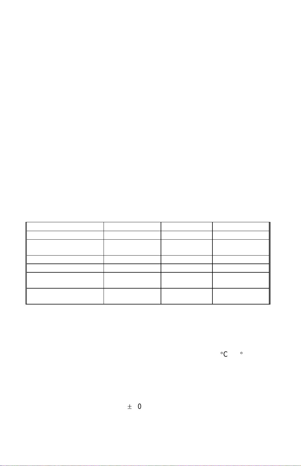
14 New Master A new more heat-sensitive master is used to
improve the printing quality.
Due to the new master material, the capacity of the
master eject box has been increased.
Because the new master surface is slippery, the
new master roll is tightened with tape [A] as shown
below to prevent the roll from becoming loose. The
master roll installation method has been changed.
(For details, refer to ‘Installation Procedure’ in the
Installation section.)
[A]
C228V502.WMF
1-6
Page 12

29 January 1998 MAJOR DIFFERENCES BETWEEN THE C223 AND THE C228
No. Item Details
15 New SP Modes The default setting for the thermal head energy for
the economy mode (SP35-2) has been changed
from -35% to -30%. (In other words, the energy
used in economy mode has been increased.)
The following SP modes are new for the C228:
SP51: Clear Multi Copy
SP52: Compress W Start Key
SP78-1: Letter/Pht Mode [CS]
SP78-2: Clear/Original
SP51 and SP78 are accessible to users. SP78
Note:
also can be registered in CS mode.
- Functions -
SP51: Resets the Combine 2 Originals or
Combined Print function (if it has been set) after the
master making process. There are two options: 0:
No, 1: Yes. “0” is the default.
Overall
Information
16 New Input/Output Check
Mode
SP52: The masters in the master eject box can be
compressed every time the Master Making key is
pressed. There are two options: 0: No, 1: Yes. “0”
is the default.
If this mode is enabled, it reduces the
Note:
possibility of the master eject belts slipping off, which
tends to occur when the master box is full.
SP78-1: Select whether the reproduction of letter
mode areas is emphasized when Letter/Photo
mode is used. There are two options: 0: Standard,
1: Emphasized. “0” is the default.
SP78-2: Select whether the image mode (letter,
photo, or letter/photo) is to be returned to the
default setting when master making is finished.
There are two options: 0: No, 1: Yes. “0” is the
default.
The following are the new items for the Input/Output
Check Mode:
Input: 51 SN: Paper Registration
(Paper Registration Sensor)
Input: 52 SN: T. Head Position
(Thermal Head Pressure Release
Sensor)
Output: 42 MOTOR: T. Head Up/Down (Turns
on
the thermal head pressure release
motor.)
1-7
Page 13

SECTION 2
DETAILED SECTION
DESCRIPTIONS
Page 14
29 January 1998 MASTER EJECT
2. DETAILED SECTION DESCRIPTIONS
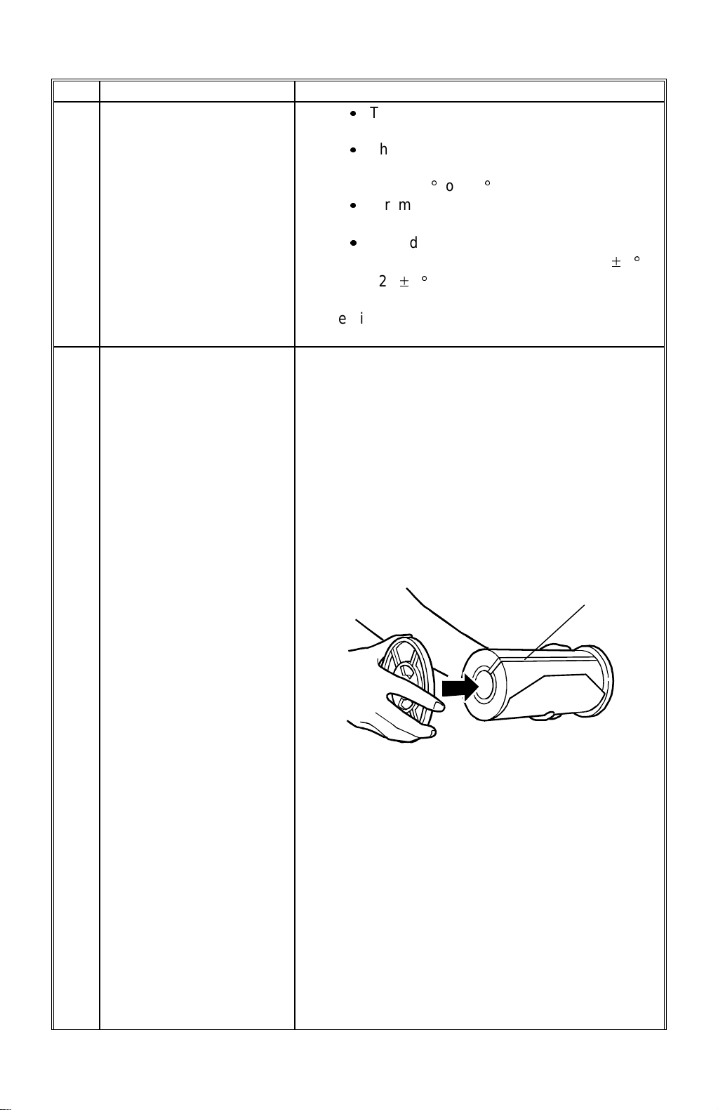
2.1 MASTER EJECT
Grooves have been added on the lower master eject rollers for better master
feeding.
CAUTION
The lower master eject roller must be installed the correct way around. The
groove [A] on the shaft (see the illustration) must be on the operation side.
Detailed
Descriptions
[A]
C228D501.WMF
2-1
Page 15
MASTER FEED 29 January 1998
2.2 MASTER FEED
2.2.1 MASTER FEED MECHANISMS
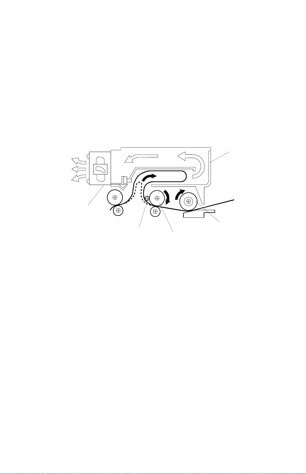
A 600 dpi thermal head and a new more heat-sensitive master is used to improve
the printing quality. The new master is thinner and has a smoother surface. The
following improvements are implemented to improve master feed.
1. Three master buffer fan motors [A] are used instead of the one fan motor used
in the C223. This generates stronger suction to guide the master into the
master box [B].
[B]
[A]
[D]
[E]
[C]
C228D502.WMF
2. To ensure correct master feed, the material of the upper master feed roller [C]
has been changed to an anti-static rubber. (A sponge-like material was used
for the C223.)
The new master feed roller [C] rotates slightly faster than the platen roller [D].
This stretches the master on the thermal head (under the platen roller) and
makes sure that the master is made accurately. A torque limiter built into the
upper master feed roller gear can release the master feed force to prevent the
master from being damaged in this area.
Also, the counter roller [E] has been added to prevent the master from
wrapping around the upper master feed roller.
2-2
Page 16

29 January 1998 MASTER FEED
[B] [C]
[A]
[D]
C228D503.WMF
3. A metal master guide plate was used between the master feed roller and
reverse roller for the C223. This was good for grounding static electricity.
However, when static electricity is grounded, the master tends to stick to the
guide plate. As a thinner master is used for the C228, the guide plate [A] is
made of a plastic material. This prevents the master from being stuck on the
guide plate surface even if static electricity is generated. Also, ribs have been
added to the new guide plate to feed the master more smoothly.
4. Four strips of mylar [B] have been added to the surface of the master guide
plates. This can prevent the master from catching on the rollers under the
master feed and reverse rollers. Other strips of mylar are used in front of the
master feed roller [C] and after the platen roller [D].
NOTE:
These mylar strips must be carefully repositioned when the rollers are
reinstalled.
Detailed
Descriptions
2-3
Page 17
MASTER FEED 29 January 1998
2.2.2 THERMAL HEAD PRESSURE RELEASE MECHANISM
[B]
[B]
[B]
[A]
[A]
[C]
[C]
[A]
[C]
[D]
[F]
[E]
C228D504.WMF
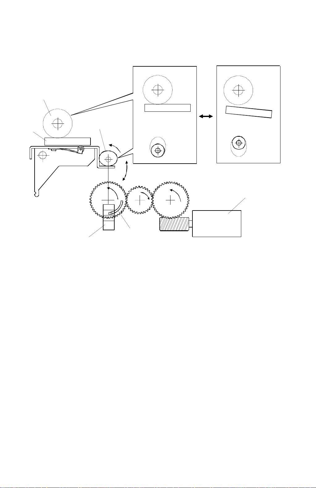
The thermal head [A] is pressed against the platen roller [B] only during the master
making process. The thermal head position is moved up and down by changing
the position of the cam [C].
The cam position is changed by the thermal head pressure release motor [D] via
gears. The thermal head pressure release sensor [E] monitors the cam position.
The sensor, which is a photointerrupter, is interrupted by the shutter mounted on
the gear [F] as the pressure release motor turns to maintain the cam position.
2-4
Page 18

29 January 1998 PAPER FEED
2.3 PAPER FEED
To improve paper feed, especially for thin paper, the paper feed roller and the
separation plate have been changed.
In addition, the shapes of the two paper feed cams (the cam profiles) have been
changed in order to make the paper registration more accurate.
With the new cams, the leading edge of the paper reaches the second feed roller
faster than before. Then, the second feed roller can start feeding the paper earlier.
Thanks to this, the second feed roller can start feeding the paper at a lower
transportation speed. (The time that the paper reaches the press roller position is
still the same, but the acceleration from the second feed roller has become more
moderate.) As a result, the paper registration has become more accurate.
Since the timing for the second feed roller to start feeding the paper was
advanced, the paper detection feeler used in the C223 could not be used. A
photocoupler is used instead. For more details about this, refer to the Printing
section.
NOTE:
1) Due to the new cams, the adjustment values for second feed roller
operation are changed. For details, refer to ‘Feed Length of the Second
Feed Roller Adjustment‘ and ‘Second Feed Roller Start Timing
Adjustment‘ in the ‘Replacement and Adjustment’ section. (The ‘Feed
Length of the Paper Feed Roller Adjustment’ procedure is still the
same.)
2) The new paper feed cams cannot be used on the older models since
those models use the paper detection feeler.
Detailed
Descriptions
2-5
Page 19

PAPER FEED 29 January 1998
2.3.1 PAPER FEED ROLLER
[B]
35.5
a
36.5 mm
[C]
C228D505.WMF
[A]
In this model, the two rubber rollers [A] on the core roller are separated. This helps
to prevent creasing of paper that can be caused by the narrower roller assembly of
the C223. (This was likely with very thin paper.)
The material of the core roller [B] was changed from plastic to metal for better
stiffness. As a result, to balance the weight of the whole paper feed roller unit, the
number of balancing weight plates on the feed roller bracket was reduced from
three to two.
Since the weight of the paper feed roller itself has increased, the roller tends to
overrun (it keeps on feeding paper) after the roller driving force stops. To prevent
this, a spring [C] which works as a brake has been added at the end of the shaft.
NOTE:
When servicing, make sure that the core roller is between 35.5 mm and
36.5 mm from the end of the shaft.
2-6
Page 20

29 January 1998 PAPER FEED
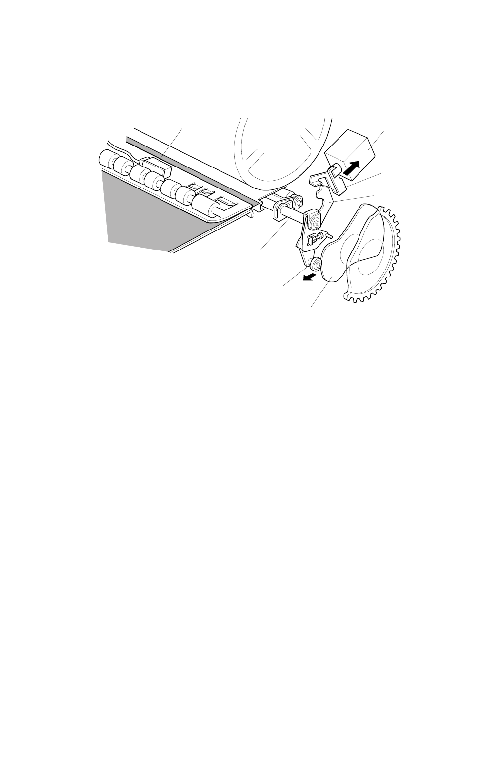
2.3.2 PAPER SEPARATION PLATE
[D]
[C]
[A]
[B]
C228D506.WMF
If the leading edge of paper stacked on the paper table curls downwards, it tends
to be caught by the separation plate and this causes a jam. The shape of the
separation plate [A] has been changed (see the diagram) to improve paper feed in
such a case.
For the same purpose, the shape of the upper edge of the entrance plate [B]
(which holds the separation plate) has been changed as shown.
The rubber part of the separation plate [C] has been lengthened to improve paper
feed, especially for thick paper. The lengthened rubber can guide the paper
leading edge to the upper separation roller [D] surface more precisely. Because of
this, the paper edge hits the upper separation roller more gently. This prevents the
paper leading edge from being damaged at the area where the separation plate
(the rubber part) contacts the upper separation roller surface. (This was likely with
thick paper.)
Detailed
Descriptions
2-7
Page 21

PRINTING 29 January 1998
2.4 PRINTING
2.4.1 OVERVIEW
Printing Pressure Cam
For better printing quality, the shape of the printing pressure cam (the cam profile)
has been changed.
The new cam applies printing pressure to the drum faster than before. The press
roller is pressed against the ink roller (the master and the drum screens are in
between) before the leading edge of the paper reaches this section.
In the C223, the press roller is pressed against the ink roller just when the paper
leading edge reaches this point. In this case, the paper leading edge is strongly
pressed against the master surface on the drum. Since the new master is thinner
and delicate, the paper leading edge tends to damage the master surface if the
same printing pressure cam is used, especially during a long printing run. (If the
master surface is damaged, ink will leak and transfer onto the paper.) The new
printing pressure cam can avoid this situation.
NOTE:
1) Because of the new printing pressure cam, the adjustment values
(angles) for printing pressure application timing and exit pawl operation
timing are changed. Refer to ‘Pressure Timing Adjustment’ and ‘Exit
Pawl Timing Adjustment’ in the ‘Replacement and Adjustment’ section.
2) The new printing pressure cam cannot be used in the older models.
Because of the new cam profile, the shift range in the backward
direction in image shifting mode has been changed from 15 mm to 10
mm. (In the forward direction, it is 20 mm as before.)
Paper Detection and Printing
In the C223, the paper detection feeler was used in order to prevent the press
roller from contacting the drum (without paper) and getting ink on it when a paper
misfeed occurred before the paper reached the press roller.
The paper detection feeler could be pressed downwards by paper since a gap
between the paper detection arm and the pressure on/off lever was created when
the widest part of the pressure cam reached the bearing on the pressure on/off
lever. With the earlier second feed roller start timing, this gap cannot be created.
Therefore, the same mechanism is not used. (The timing was changed to make
paper registration more accurate; see the Paper Feed section for details.)
NOTE:
Instead of the paper detection feeler, the registration sensor (a photocoupler) is
used. When the sensor detects the paper, the printing pressure solenoid energizes
to start applying the printing pressure. (In the C223, the printing pressure solenoid
was energized as soon as paper feed started.) The sensor is also used as a paper
jam detector.
For the details of the paper detection feeler operation, refer to the C223
Service Manual. (Section 5.2, ‘Paper Detection And Printing Pressure
On/Off Mechanism’ in the ‘Detailed Section Descriptions’ section.)
2-8
Page 22

29 January 1998 PRINTING
For more details about this mechanism, refer to the following ‘Paper Detection and
Printing Pressure On/Off Mechanism’ section.
Quality Start
The detection arm release solenoid which was used in the C223 has been
removed. Since the paper detection feeler has been removed, the detection arm
release solenoid is not necessary to start the drum stroke operation in the quality
start mode.
When the drum stroke operation starts, the printing pressure solenoid turns on.
This disengages the pressure on/off lever and starts applying the printing
pressure.
Detailed
Descriptions
NOTE:
For the details of the quality start mode operation, refer to the C223
Service Manual. (Section 5.4 ‘Quality Start Operation’ in the ‘Detailed
Section Descriptions’ section.)
2-9
Page 23
PRINTING 29 January 1998
2.4.2 PAPER DETECTION AND PRINTING PRESSURE ON/OFF
MECHANISM
[A]
[B]
[C]
[D]
[E]
[G]
[F]
C228D507.WMF
When the paper is detected by the paper registration sensor [A], the printing
pressure solenoid [B] is energized. The stopper arm [C] then disengages the
pressure on/off lever [D]. The pressure on/off lever, which is connected to the end
of the press roller arm [E], starts moving when the printing pressure cam [F] starts
moving; the cam moves bearing [G], which is on the lever. The press roller is
pressed against the ink roller.
The printing pressure solenoid is de-energized when the printing pressure sensor
is activated; this is soon after it is energized. The stopper arm [C] returns and is
pressed against the pressure on/off lever, due to tension from a spring. (The
stopper arm just rides on the edge of the pressure on/off lever at this time.) To
finish applying the printing pressure, the bearing [G] on the pressure on/off lever is
pushed by the printing pressure cam and the lever turns clockwise, until it is
engaged by the stopper arm.
If the next sheet of paper is detected by the registration sensor within a certain
period, the printing pressure solenoid is again energized to disengage the pressure
on/off lever. The printing pressure for the next sheet of paper starts being applied.
If the registration sensor is not activated, the machine detects a paper misfeed
condition (Location B Misfeed). In this case, the printing pressure solenoid stays
de-energized and the printing pressure is not applied. This can prevent the press
roller contacting the drum (without paper) and getting ink on it because of the
paper misfeed.
NOTE:
In the C223, Location B Misfeed was detected when the printing pressure
sensor was not activated within a certain period.
2-10
Page 24
29 January 1998 IMAGE PROCESSING
2.5 IMAGE PROCESSING
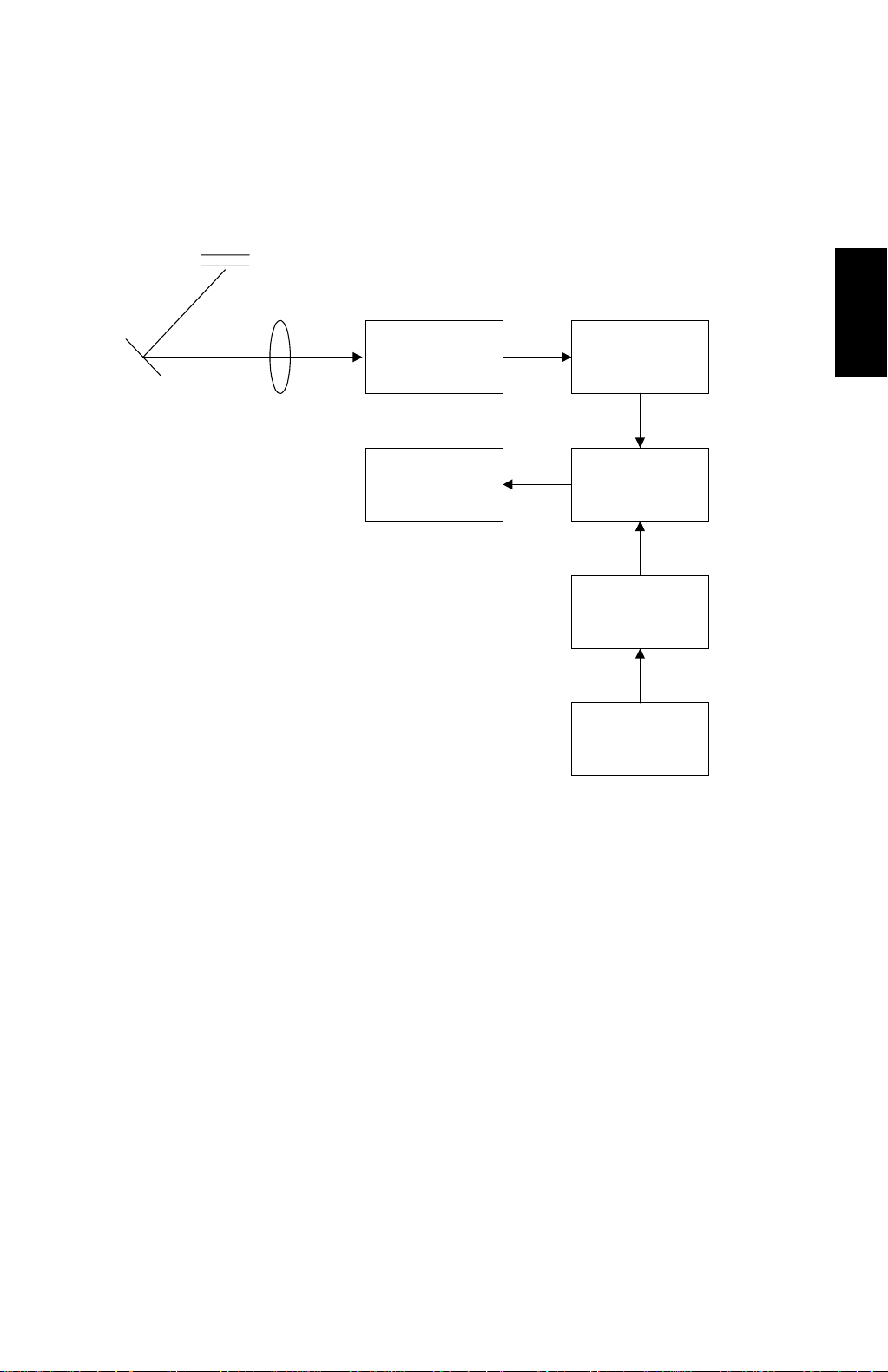
2.5.1 OVERVIEW
Analog signal
CCD PCB
Thermal Head
1-bit
A/D Conversion
PCB
6-bit
Image
Processing PCB
Main Control
PCB
Image Settings
Operation Panel
C228D508.WMF
Detailed
Descriptions
The light reflected from the original goes to the CCD, which converts the light
signal into an analog electrical signal. The analog signal is sent to the A/D
conversion PCB, where it is changed to 6-bit digital data. The 6-bit data is changed
to 1-bit data in the image processing PCB and it goes to the thermal head. The
thermal head drive circuit is built into the image processing PCB.
The 6-bit to 1-bit conversion procedure depends on the image settings on the
operation panel.
2-11
Page 25
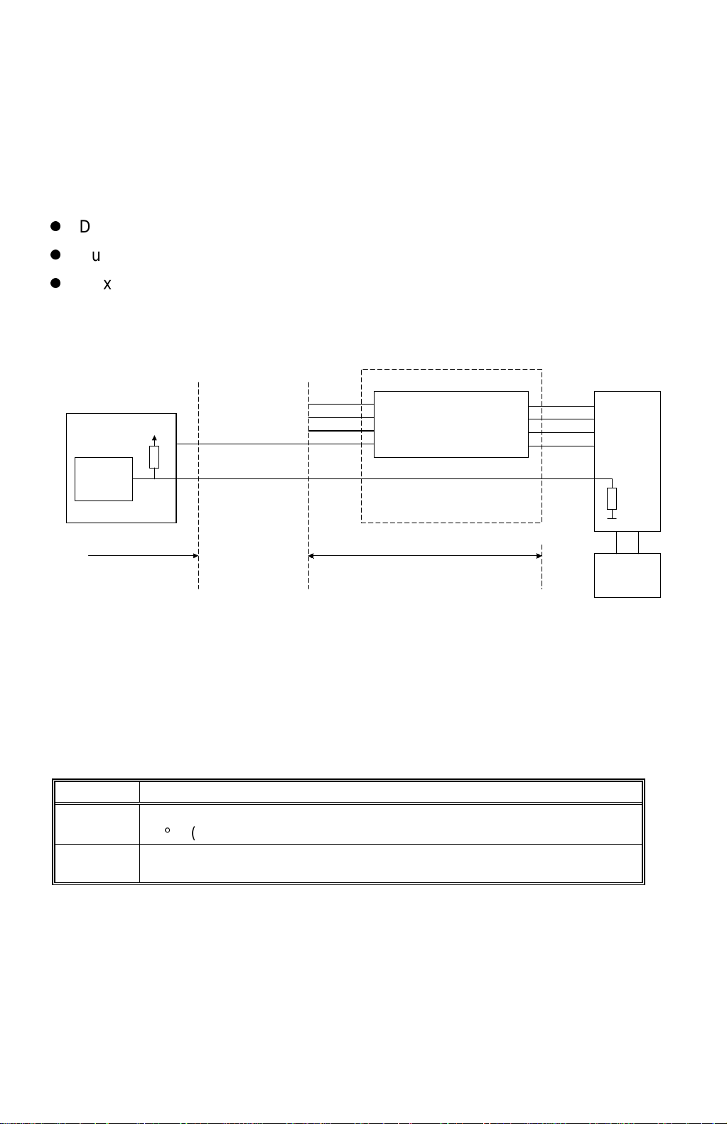
IMAGE PROCESSING 29 January 1998
2.5.2 MASTER MAKING
The operation of the thermal head is just like that of the C223, except that the
thermal head drive circuit has been built into the image processing board.
The new 600 dpi thermal head is used with the new more heat-sensitive master.
The specifications of the thermal head are as follows:
z
Density of Thermal Heating Elements: 600 dpi
z
Number of Thermal Heating Elements: 7168 dots
z
Maximum Master Making Width: 303.45 mm
2.5.3 THERMAL HEAD PROTECTION
Pulse Generator
Circuit
A/D
Conversion
Circuit
Main Control PCB
CN111-A8 CN404-A8
CN111-A1 CN404-A1
/ P:CLK
/ P:LSYNC
/ P:DATA
/ ENLPLS
Thermal Head Drive Circuit
Gate Array
Image Processing PCB
DI1~4
Thermal Head
CK1~4
LAT1~4
STB1~4
Thermistor
C228D509.WMF
DC/DC
Converter
PCB
The thermistor on the thermal heat prevents it from overheating when continuously
processing a solid image.
The CPU checks for abnormal conditions when the Master Making key is pressed,
and indicates an SC code on the operation panel under the following conditions:
SC Code Conditions
E-04 The thermistor on the thermal head detected a temperature of over
54qC. (CN111-A1 is below 1.17 volts.)
E-09 The thermistor is open, or related connectors are not connected.
(The signal level between CN111-A1 and GND is over 4.9 volts.)
2-12
Page 26
29 January 1998 PAPER MISFEED DETECTION
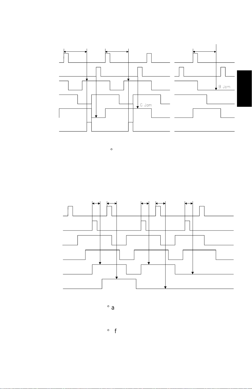
2.6 PAPER MISFEED DETECTION
175°
1st Drum Position Sensor
2nd Drum Position Sensor
Paper Registration Sensor
Printing Pressure Sensor
2nd Paper Exit Sensor
Printing Pressure Solenoid
175°
175°
C228D510.WMF
[a] When the drum has rotated 175q after activating the 1st drum position sensor,
if the paper registration sensor is still OFF, a paper misfeed (Location B jam) is
detected.
[b] When the 2nd drum position sensor turns on, if the 2nd paper exit sensor
remains ON, a paper misfeed (Location G jam) is detected.
Detailed
Descriptions
20° 25° 25° 20°
1st Drum Position Sensor
2nd Drum Position Sensor
Paper Registration Sensor
Printing Pressure Sensor
1st Paper Exit Sensor
2nd Paper Exit Sensor
20°
BE Jam
E Jam
C228D511.WMF
[c] When the drum has rotated 20q after activating the 2nd drum position sensor, if
the 1st paper exit sensor is still OFF, a paper misfeed (Location BE jam) is
detected.
[d] When the drum has rotated 25q after activating the 1st drum position sensor, if
the 2nd paper exit sensor is still OFF, a paper misfeed (Location E jam) is
detected.
2-13
Page 27

SECTION 3
INSTALLATION PROCEDURE
Page 28
29 January 1998 INSTALLATION REQUIREMENTS
3. INSTALLATION
3.1 INSTALLATION REQUIREMENTS
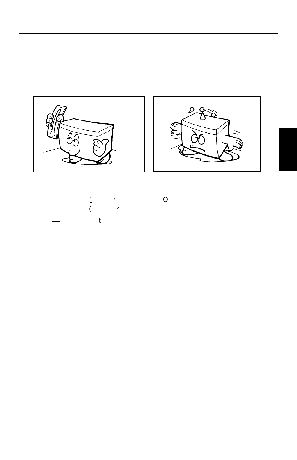
3.1.1 OPTIMUM ENVIRONMENTAL CONDITIONS
Installation
Temperature
Humidity
C223I518.PCX
10 to 30qC
(50 to 86qF)
20 to 90 % RH The machine must be level within
On a strong and level base.
5 mm (13/64") both front to rear
and left to right.
C223I519.PCX
3-1
Page 29
INSTALLATION REQUIREMENTS 29 January 1998
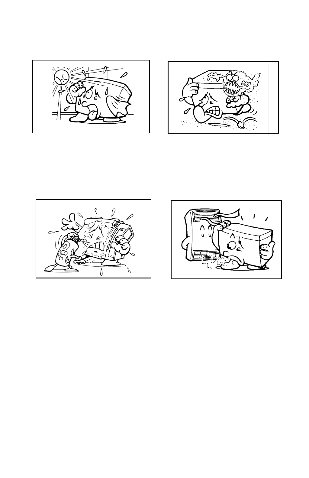
3.1.2 ENVIRONMENTS TO AVOID
Locations exposed to direct
C223I520.PCX
Dusty areas.
C223I521.PCX
sunlight or strong light (more than
1,500 lux).
C223I523.PCX
C223I525.PCX
Areas with corrosive gases. Locations directly exposed to cool air
from an air conditioner or reflected
heat from a space heater. (Sudden
temperature changes from low to
high or vice versa may cause
condensation within the machine.)
3-2
Page 30
29 January 1998 INSTALLATION REQUIREMENTS
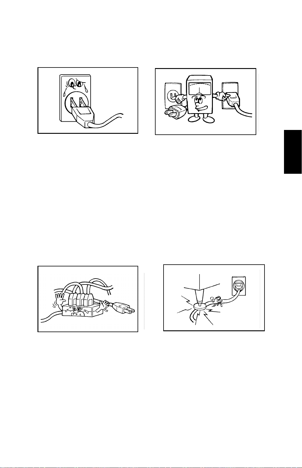
3.1.3 POWER CONNECTION
C223I524.PCX
Securely connect the power cord
to a power source.
Make sure that the wall outlet is
near the machine and easily
accessible.
Make sure the plug is firmly
inserted in the outlet.
C223I516.PCX
Voltage must not fluctuate more than
10%.
Installation
C223I515.PCX
C223I517.PCX
Avoid multiwiring. Do not pinch the power cord.
3-3
Page 31

INSTALLATION REQUIREMENTS 29 January 1998
(
)
3.1.4 ACCESS TO THE MACHINE
Place the machine near a power source, providing clearance as shown below.
Paper Delivery
Table
More than 60 cm
(23.7”)
20 cm (8.0”)
Paper
Feed
Table
More than 60 cm
(23.7”)
More than 60 cm
23.7”
C223I526.WMF
3-4
Page 32

29 January 1998 ACCESSORY CHECK
3.2 ACCESSORY CHECK
Make sure that you have the following accessories.
1. Operating Instructions (except for -27 models)
2. NECR (-17, -27 models only)
3. End Plate Prop
4. Decal - Mode
5. Decal - Key Top Cover (OEM machines only)
6. Model Name Plate (OEM machines only)
7. Decal - Master Set (-27 models only)
Installation
3-5
Page 33

INSTALLATION PROCEDURE 29 January 1998
3.3 INSTALLATION PROCEDURE
[A]
[A]
C223I501.PCX
CAUTION
C223I500.PCX
Do not hold the scanner unit when pushing the machine or the scanner unit
safety switch may be damaged.
1. Place the machine on the table.
NOTE:
The screw holes in the bottom plate of the machine must line up with
the screw holes in the table.
[A]
2. Remove the strips of tape [A] securing the covers and units shown above.
[B]
[D]
[C]
C223I502.PCX
3. Open the front door and slide out the drum unit [B].
4. Open the master clamper and remove the clamp [C].
5. Open the paper feed table and remove the cardboard cover [D] protecting the
paper feed roller.
3-6
Page 34

29 January 1998 INSTALLATION PROCEDURE
6. Slide the scanner unit to the left (as seen from the operation side) and remove
the two strips of tape securing the master box.
[G]
[F]
[H]
[E]
C223I503.PCX
C223I504.PCX
7. Open the paper delivery table and remove the strip of tape [E] protecting the
end fence.
8. Remove the cardboard [F] under the scanner unit.
9. Open the scanner unit and change the position of screws [G] from the transport
position to the operating position.
10. Open the doors (2 strips of tape [H]) of the optional table and take out the
plastic bag containing 2 screws.
Installation
3-7
Page 35

INSTALLATION PROCEDURE 29 January 1998
[B]
[A]
[C]
C223I505.wmf
11. Raise the front side of the machine and position the base pad [A] under the
machine. Then raise the rear side of the machine and position the other base
pad [B] under the machine.
12. Secure the machine to the table with the two screws [C] packed with the table.
3-8
Page 36

29 January 1998 INSTALLATION PROCEDURE
13. Open the paper feed table [A] and neatly
stack some printing paper on the table.
14. Slide the paper feed side plates [B] gently up
against the paper stack.
[B]
C223I506.PCX
[A]
15. Open the paper delivery table [C] and adjust
the position of the end plate [D] and the side
plates [E] to match the printing paper size.
Refer to the paper size scale on the table.
[D]
16. Install the ink cartridge [F].
1) Open the front door and lower the ink
holder [G].
2) Remove the ink cartridge cap.
3) Insert the ink cartridge in the ink holder
and raise the ink holder to the original
position.
4) Close the front door.
[C]
[E]
Installation
C228v000-2.WMF
[F]
C223I508.PCX
[G]
17. Slide the scanner unit all the way to the left,
and take the master spools [H] out.
3-9
[H]
C223I514.wmf
Page 37

INSTALLATION PROCEDURE 29 January 1998
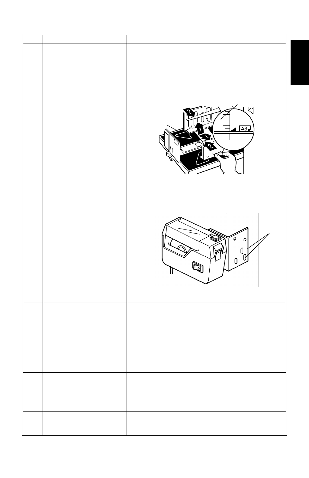
18. Install the master roll.
1) Take out the master roll from the plastic bag.
NOTE:
x
Firmly grasp the master roll
since it is very slippery.
x
Do not remove the strip of
the tape holding the master
roll till step 5 below.
C228I500.WMF
[A]
2) Attach a spool [A] to each end of the
master roll [B].
3) Push the pressure release lever [C] to the
C228V002-2.WMF
[C]
left.
4) Set the master roll in the machine as shown
in the illustration.
5) Remove the tape holding the master roll as
shown to the right.
NOTE:
x
Hold the spools by hand to
C228I501.PCX
remove the tape easier.
[B]
x
It is better to remove the
tape completely, but leave
any parts that remain on the
spools or in the core.
6) Insert the leading edge of the master roll
under the platen roller.
7) Return the pressure release lever to the
original position.
8) Plug in the power cord and turn on the main
switch.
9) Press the master cut button.
10) Open the master box cover and remove the
cut strip of master paper.
NOTE:
Check that the paper on the master roll is not bent or creased.
11) Close the scanner unit.
3-10
C228I502.WMF
Page 38

29 January 1998 INSTALLATION PROCEDURE
[A]
C223I512.PCX
19. Idle the machine to distribute ink on the drum.
1) Press the Reset key while holding down the "0" key on the operation panel.
<
2) If
blinks on the operation panel when the machine stops, press the Reset
key again.
Installation
20. Make some test prints to check the machine.
1) Raise the platen cover and place an original face down on the exposure
glass [A]. Make sure the original is flush with the left scale and aligned with
the proper paper size marks.
2) Press the Master Making key.
3) Select the lowest print speed (1) with the Speed key and press the Print
Start key. Make prints at this speed until the print image density stabilizes.
NOTE:
1) Usually, about 30 prints need to be made before the image fully
stabilizes.
2) Check the image quality after the print image density is stabilized.
3-11
Page 39

INSTALLATION PROCEDURE 29 January 1998
21. If necessary, change the language for the LCD guidance as follows:
1) Turn the main switch off and unplug the machine.
2) Remove the right front cover (4 screws).
3) Change the DIPSW 102-1, 2, 3 settings. The following table shows the
setting for each language.
DPS102 LCD Display
123
ON ON OFF English (Default)
OFF OFF ON German
ON OFF ON French
OFF ON ON Spanish
ON ON ON Italian
4) Reinstall the right front cover (4 screws).
3-12
Page 40

SECTION 4
SERVICE TABLES
Page 41

29 January 1998 SERVICE REMARKS
4. SERVICE TABLES
4.1 SERVICE REMARKS
1. If a circuit breaker or a fuse opens, check and remove the cause of the
overcurrent before resetting the breaker or replacing the fuse.
2. If the thermal head or the power supply unit is replaced, thermal head voltage
adjustment is required.
3. Do not touch the edge of the cutter blade with bare hands.
4. Be careful not to drop the master eject unit when removing the eject unit guide
shaft.
5. If the paper feed guide plate is removed, make sure that the guide plates do
not touch the lower second feed roller when putting back the guide.
6. When putting back the lower separation roller, make sure that the front and
rear separation levers move smoothly.
7. If the slowest speed is faster than 60 rpm, the sorter cannot keep up with the
machine and a TS sorter jam might occur.
8. Do not energize the master feed and master eject clamper solenoids for longer
than 10 seconds.
Tables
Service
9. When adjusting the ink roller gap, check the gap at the right, center, and left
positions.
10. The ink detection adjustment should be made under normal conditions (20
C/65%RH).
11. When removing the pressure cam drive gear, do not loosen the two deeply
recessed bolts.
12. If the main drive belt has been removed, check the relationships between the
drum drive gear, printing pressure cam, and the paper feed cams after
replacing the belt. Adjust if necessary.
13. Do not keep on pressing the Image Position key if the image position sensor is
broken or removed. The plastic gears between the metal gears may break.
4-1
Page 42

SERVICE TABLES 29 January 1998
4.2 SERVICE TABLES
4.2.1 MAINTENANCE TABLES
Lubrication Points
Lubricate after removing adhering ink and paper dust at yearly intervals.
Section Lubrication Point Type Location
Drive Speed Reduction Gears of
the Main Motor
Gears of the Drum Drive
Shaft
Image
Positioning
Paper Feed Paper Feed Sector Gear (Fig.1- J)
Drum Drum Drive Gear Grease (Shell
Printing
Pressure
Master Eject Master Pressure Plate
Paper Exit Air Pump Drive Gears (Fig. 6-T)
ADF Bearings for the Feed Roller
Others Edge of Each Cam Grease (Shell
Spiral Track of the Cam Gear (Fig.1- K)
Second Feed Sector Gear (Fig.1- F)
Gear of the Paper Feed Cam
Shaft
Paper Table Slide Groove Both front and rear
Paper Table Drive Gear (Fig.1- G)
Bearings for the Upper
Separation Roller Shaft
Bearings for the Paper Feed
Roller Shaft
Master Clamper Sector Gear (Fig.3- O)
Master Clamper Pinion Gear (Fig.3- P)
Ink Pump Drive Gear (Fig.3- M)
Between Printing Pressure
Arm [Q] and Printing
Pressure Stay [Q']
Pressure Spring Link (Fig.1- C)
Grooves
Rounded Ends of the Master
Pressure Plate Drive Arms
Inside of the Air Pump Piston Grease
Shaft
Grease
(Shell Albania
No.2)
Motor oil
(SAE No.20)
Albania No. 2)
Grease
(Shell Albania
No. 2)
(Mobil Ep-1)
Motor oil
(SAE No. 20)
Albania No. 2)
(Fig.1- E)
On the inside and
outside of the
frame (Fig.1- B)
(Fig.1- A)
(Fig.1- H)
(Fig.1- I)
(Fig.2- L)
(Fig.3- N)
Both front and rear
(Fig.4- Q)
Both front and rear
(Fig.5- S)
(Fig.5- R)
(Fig. 6-U)
Both front and rear
(Fig. 7-V)
(Fig.1- D)
4-2
Page 43

29 January 1998 SERVICE TABLES
[Fig1]
[D]
[J]
[I]
[H]
[G]
[K]
[A]
[F]
C223M500.PCX
[B]
[C]
[D]
[E]
[Fig2]
Tables
Service
[O]
[L]
C223M501.PCX
[Fig 3]
[P]
[M]
[N]
C223M502.PCX
4-3
Page 44

SERVICE TABLES 29 January 1998
[Fig 4]
[Q’]
[Fig 5]
[R]
[Q]
C223M503.PCX
[S]
[Fig 6]
[U]
[T]
C223M509.PCX
C223M504.PCX
[Fig 7]
4-4
[V]
C223M510.WMF
Page 45

29 January 1998 SERVICE TABLES
User's Maintenance
Advise the customer to clean each item regularly. Clean the following items at
every EM call if necessary.
Section Cleaning Point Cleaner Interval
Optics Original Platen Cover Cloth and water
Exposure Glass Cloth and glass cleaner
Paper Feed Paper Feed Roller Cloth and soap and
water
Paper End Sensor Dry cloth
Paper Length Sensor
Printing Press Roller Cloth and soap and
water
ADF Original Feed Rollers
At every EM call
Periodic Inspection (every 6 months)
Section Item Standard Procedure
Optics Original Platen Cover Wipe off stains using a soft cloth
moistened with ethyl alcohol.
Exposure Glass Wipe with a dry cloth.
Paper Feed Paper Feed Roller Wipe off ink and paper powder using a
cloth moistened with ethyl alcohol.
Upper and Lower
Second Feed Rollers
Upper and Lower
Separation Rollers
Printing Press Roller
ADF Pick-up Roller
Feed Roller
Separation Roller
Wipe off paper powder using a cloth
moistened with water.
Tables
Service
4-5
Page 46

SERVICE TABLES 29 January 1998
Periodic Inspection (every 12 months)
Section Item Standard Procedure
Optics Back side of the
Exposure Glass
Mirrors Use a blower brush.
Xenon Lamps Wipe with a dry cloth.
Master Eject Upper and Lower Master
Eject Rollers
Drum Inside and outside of the
Drum
Ink Holder
Master Making Platen Roller Wipe off paper powder using a cloth
Others First and Second Paper
Exit Sensors
Master Eject Sensor
Drum Master Sensor
Wipe with a dry cloth.
Wipe off ink and paper powder using a
cloth moistened with ethyl alcohol.
Wipe off built-up ink and paper powder
using a cloth moistened with ethyl
alcohol.
moistened with water.
Check the performance of all the
sensors. Remove stains from the
sensors using a dry cloth.
4-6
Page 47

29 January 1998 SERVICE TABLES
4.2.2 SERVICE CALL CODES
Code Problem Possible Causes
Main Body
E-01 Neither the right nor the left cutter
switch turns off within 3 seconds of the
cutter motor starting.
E-02 Malfunction in the paper table drive
section.
1. The paper table lower limit sensor or
paper table height sensor does not
turn on within 7 seconds.
2. The LCT tray drive motor does not
stop within 25 seconds.
3. The upper limit sensor does not turn
or within 8 seconds after the LCT
cassette bottom plate drive motor
starts.
E-04 The temperature of the thermal head is
greater than 54qC when the Master
Making key is pressed
E-05
E-06
E-09 The signal level between CN104-A1
E-10 The CPU detects an abnormality in the
E-11 Encoder output does not change within
Malfunction in the image shifting
section.
The drum rotation sensor detects an
incorrect motor speed.
and GND is over 4.9 volts.
pulse signals from the image
processing PCB. These pulses
determine the energy to be applied to
the thermal heating elements.
3 seconds of the main switch being
turned on or the Clear Mode key being
pressed.
1) Drive wire cut
2) Drive section malfunction
3) Defective cutter switch
1) Drive worm gear broken
2) Mounting screw of the
worm gear broken
3) No power supply
1) Excessive thermal head
temperature
2) Thermistor short
1) Image position sensor
connector disconnected
2) Defective image position
sensor
1) Drum lock
2) No power supply
1) The thermistor is open.
1) Defective thermistor
2) Related connectors are
not.
1) Defective image position
motor
2) No power supply
Tables
Service
4-7
Page 48

SERVICE TABLES 29 January 1998
Code Problem Possible Causes
E-12 1. The upper or lower pressure plate
sensor remains activated for more
than 4 seconds after the pressure
plate motor starts turning.
2. The lower pressure plate sensor is
not activated within 8 seconds of the
pressure plate motor starting to turn
even though the upper pressure
plate sensor is de-activated.
3. The upper pressure plate sensor is
not activated for more than 8
seconds after the pressure plate
motor starts to turn even though the
lower pressure plate sensor is deactivated.
E-13 1. During scanner initialization:
The home position sensor
remains activated for more than 4
seconds.
The home position sensor is not
activated within 2 seconds.
2. The home position sensor is not
activated within 7 seconds when the
scanner returns after finishing
making the master or scanning.
Pressure plate drive
mechanism malfunction.
1) Defective home position
sensor
2) Scanner motor lock
E-14 EMF sorter communication error.
Sorters
E-21 The 1st transport motor speed is
abnormal.
E-26 The 1st sorter helical wheel H.P.
sensor status does not change even if
the bin shift motor drive signal is
applied.
The bin shift motor rotation sensor
status does not change even if the bin
shift motor drive signal is applied.
E-27 The 1st sorter jogger bar H.P. sensor
status does not change even if the
jogger bar motor drive signal is applied.
1) Defective 1st transport
motor
2) Defective 1st transport
motor rotation sensor.
1) Defective bin shift motor
2) Defective helical wheel
H.P. sensor
3) Defective bin shift motor
rotation sensor
1) Defective jogger bar
motor
2) Defective jogger bar H.P.
sensor
4-8
Page 49

29 January 1998 SERVICE TABLES
Code Problem Possible Causes
E-28 The 1st sorter staple position switch or
staple unit movement switch status
does not change even if the staple unit
shift motor drive signal is applied.
E-29 The 1st transport sort mode position
sensor or the 1st transport non-sort
mode position sensor status does not
change even if the delivery table motor
drive signal is applied.
E-34 The 2nd transport motor rotation sensor
speed is abnormal.
E-36 The 2nd sorter helical wheel H.P.
sensor status does not change even if
the bin shift motor drive signal is
applied.
The bin shift motor rotation sensor
status does not change even if the bin
shift motor drive signal is applied.
E-37 The 2nd sorter jogger bar H.P. sensor
status does not change even if the
jogger bar motor drive signal is applied.
E-38 The 2nd sorter staple position sensor or
staple unit movement sensor status
does not change even if the staple unit
shift motor drive signal is applied.
1) Defective staple unit shift
motor
2) Defective jogger bar H.P.
sensor
3) Defective staple unit
movement switch
1) Defective 1st transport
sort mode position
sensor
2) Defective 1st transport
non-sort position sensor
3) Defective delivery table
motor
1) Defective 2nd transport
motor
2) Defective 2nd transport
motor rotation sensor
1) Defective bin shift motor
2) Defective helical wheel
H.P. sensor
3) Defective bin shift motor
rotation sensor
1) Defective jogger bar
motor
2) Defective jogger bar H.P.
sensor
1) Defective staple unit shift
motor
2) Defective jogger bar H.P.
sensor
3) Defective staple unit
movement switch
Tables
Service
4-9
Page 50

SERVICE TABLES 29 January 1998
4.2.3 DIP SWITCHES, LEDS, VRS, TPS (ON THE MAIN CONTROL
PCB)
DIP Switches
DIP Switch Function Remarks
DIP SW101 Do not use. Must be off at all times.
DPS 102 LCD Display
123
ON ON OFF English
OFF OFF ON German
ON OFF ON French
OFF ON ON Spanish
ON ON ON Italian
OFF OFF OFF For Japanese Machines
ON OFF OFF
OFF ON OFF
DPS 102 ON OFF
4 DFII (Type 50) Also see SP8. DFI
5 Print and master counters
increment by two counts when
the A3 drum is used (NRG
setting). Also, see SP86.
6 Inch version A4 version
NOTE:
The DF setting can be changed using SP8. When the memory clear
Print and master counters
increment by one regardless of
the drum size.
(SP60) is performed, the SP8 setting depends on the DPS102-4
setting. Later, if the SP mode is changed but not the DPS, the SP
mode setting takes priority. This note also applies to DPS 102-5.
Photodiodes
LED Component Remarks
LED101 1st Paper Exit Sensor When paper is detected, the LED lights.
LED102 Drum Master Sensor When a master is on the drum, the LED
lights.
LED103 2nd Paper Exit
Sensor
LED104 Master Eject Sensor When a master is under the master eject
LED105 Ink Detection When ink is present, the LED lights.
LED106 Main Motor When the main motor turns on, the LED
When paper is detected, the LED lights.
sensor, the LED lights.
lights.
4-10
Page 51

29 January 1998 SERVICE TABLES
VRs
VR Function
VR101 1st Paper Exit Sensor Adjustment
VR102 Drum Master Sensor Adjustment
VR103 2nd Paper Exit Sensor Adjustment
VR104 Master Eject Sensor Adjustment
VR105 Adjustment for Drum Speed 5 (120 rpm)
VR106 Adjustment for Drum Speed 1 (60 rpm)
TPs
TP Function
TP101 1st Paper Exit Sensor Voltage
TP102 Drum Master Sensor Voltage
TP103 2nd Paper Exit Sensor Voltage
TP104 Master Eject Sensor Voltage
TP105 Ink Detection Voltage
TP106 Drum Rotation Sensor Voltage
TP107 GND
Tables
Service
4.2.4 EXPECTED LIFE OF PARTS
Section Part Description Expected Life
Scanner Xenon Lamp 15,000 originals
Master Feed/Master
Making
Drum Drum Cloth Screen 2 years or 1,200,000 prints
Paper Feed Paper Feed Rubber Side Plate 2 years or 1,200,000 prints
Printing Press Roller 2 years or 1,200,000 prints
Delivery Transport Belt 2 years or 1,200,000 prints
Thermal Head
Reverse Roller
Platen Roller 30,000 masters
Upper Master Feed Roller 1 year or 30,000 masters
Paper Feed Roller 6 months or 300,000 prints
Upper Separation Roller 1 year or 600,000 prints
Lower Separation Roller 2,000,000 prints
2nd Feed Roller Brake Belt 1,000,000 prints
2nd Feed Roller Gear 1,000,000 prints
Separation Plate 1 year or 600,000 prints
30,000 masters
30,000 masters
4-11
Page 52

SERVICE TABLES 29 January 1998
4.2.5 SPECIAL TOOLS
Description Part Number
Test Chart R-21 99992131
Resolution Chart A0129110
Drum Gauge C2009001
Image Shifting Gauge C2009002
4-12
Page 53

29 January 1998 SERVICE PROGRAM MODE
4.3 SERVICE PROGRAM MODE
4.3.1 SERVICE PROGRAM MODE OPERATION
The service program (SP) mode is used to check electrical data, change modes,
or change adjustment values.
Service Program Mode Access Procedure (for engineers)
All service program modes can be accessed with this procedure.
1. Press the following keys on the operation panel in the following order:
Case 1:
a) Clear Modes key
b) Clear key
c) Combine 2 Originals key
d) Enter key
Case 2:
a) Turn off the power switch
b) Press the Enter key, Stop key, and Clear key simultaneously
c) Turn on the power
Tables
Service
2. The following is displayed on the LCD when the SP mode is accessed.
SP—MODE
PROGRAM No. 0
3. Using the number keys, enter the desired SP mode number (listed in the
service program table.)
NOTE:
4. To cancel the SP mode, press the Clear Modes key.
The SP mode number can be shifted up or down by pressing the Zoom
key ("+" or "-").
4-13
Page 54

SERVICE PROGRAM MODE 29 January 1998
Service Program Mode Access Procedure (for users)
This procedure allows users to access only the service program modes that are
marked with an asterisk in the service program table.
1. Press the following keys on the operation panel in the following order:
a) Clear Modes key
b) Clear key
c) Enter key
2. The following is displayed on the LCD when the SP mode is accessed.
SP—MODE
PROGRAM No. 0
3. Using the number keys, enter the desired SP mode number (listed in the
service program table).
4. To cancel the SP mode, press the Clear Modes key.
Change Adjustment Values or Modes
1. After entering the desired SP mode number, press the Enter key. The current
value or mode will be displayed on the LCD (at the end of the second line).
2. Enter the desired value or mode using the number keys (listed in the service
program table).
Use the Memory/Class key to toggle between + and -.
3. Press the Enter key to store the desired value or mode.
4. To cancel the SP mode, press the Clear Modes key.
4-14
Page 55

29 January 1998 SERVICE PROGRAM MODE
4.3.2 SERVICE PROGRAM TABLE
*: Accessible by a customer<_>**: Can be registered in CS mode
j
: A4 version i: LT version
No. Display Function Data Factory
Setting
1 On line Enables On Line key
operation.
2 FDC Type 10 Used only in Japan 0: No
3 Key Counter Enables key counter
operation.
4 Key Card Used only in Japan. 0: No
5 EMF Sorter Selects the number of
sorters.
7-1 DS/TS Sorter Enables TS20A/B
operation.
7-2 Auto Reset Time Specifies the auto
reset time.
8 ADF Select Informs the machine if
DF Unit Type 50 is
installed.
*10. Min. Print Limits the minimum
print quantity that can
be entered.
*11 Max. Print Limits the maximum
print quantity that can
be entered.
*12
j
: A4 o A3
Mag. Ratio
i
HLT o LG
Mag. Ratio
*13
j
: A4 o B4
Mag. Ratio
i
LT o DLT
Mag. Ratio
*14
j
: B4 o A3
Mag. Ratio
i
LG o DLT
Mag. Ratio
*15 Full Size Adjusts the full size
Adjusts the fixed
magnification ratio.
j
: From A4 to A3
i
: From 51/2" x 81/2"
to 81/2" x 14"
Adjusts the fixed
magnification ratio.
j
: From A4 to B4
i
From 51/2" x 81/2"
to 11" x 17"
Adjusts the fixed
magnification ratio.
j
: From B4 to A3
i
From 81/2" x 14" to
11" x 17"
magnification ratio.
0: No
1: Yes
1: Yes
0: No
1: Yes
1: Yes
0: No sorters
1, 2, 3, 4, or 5:
Sorters present
0: No
1: Yes
0: No
1-5: min.
0: DF1 (or no
DF)
1: DF2 (type 50)
0 to 9999 0
0 to 9999 9999
50 to 200%
50 to 200%
50 to 200%
50 to 200% 100%
0
0 Keep at 0.
0
0
0 Input 1 to 5 to
0 If "1" is selected
0
0
j
: 141%
i
: 155%
j
: 122%
i
: 129%
j
: 115%
i
: 121%
Comments
indicate the
number of
sorters.
in 7-1, the
machine goes to
Auto Reset
Time setting
mode.
Tables
Service
4-15
Page 56

SERVICE PROGRAM MODE 29 January 1998
No. Display Function Data Factory
Setting
*16 Page Margin Adjusts the create
margin magnification
ratio.
*17
*18
*19
*20 Buzzer On Turns the beeper ON
*21 Prints/Master
22 Read Image Area Not used - 0 Not used
*23 Online Paper
25 Sorter Feed
26-1 Sorter Priority Determines the sorter
26-2 0: 1st/2nd
: A3 o B4
j
Mag. Ratio
: LG o LT
i
Mag. Ratio
: B4 o A4
j
Mag. Ratio
: ** o LT
i
Mag. Ratio
: A3 o A4
j
Mag. Ratio
: DLT o LT
i
Mag. Ratio
Cost
Size
Speed
1: 2nd/1st
2. 1st
3. 2nd
Adjusts the fixed
magnification ratio.
: From A3 to B4
j
: From 81/2" x 14" to
i
81/2" x 11"
Adjusts the fixed
magnification ratio.
: From B4 to A4
j
: From 11" x 15" to
i
81/2" x 11"
Adjusts the fixed
magnification ratio.
: From A3 to A4
j
: From 11" x 17" to
i
81/2" x 11"
or OFF
Adjusts the cost ratio
of masters to prints for
accounting purposes.
Used only in Japan 0: A6
Determines the
transport belt speed in
the TS sorter.
priority.
Determines the sorter
priority when "1" is
selected in SP26-1.
50 to 200% 93%
50 to 200%
50 to 200%
50 to 200%
0: No
1: Yes
0 to 50 0 The set number
1: A5
0: -20%
1: -15%
2: -10%
3: -5%
4: +5%
5: +10%
6: +15%
7: +20%
8: +25%
9: +30%
10: 0%
0: Normal
1: Others
0: 1st sorter first
1: 2nd sorter first
2: 1st sorter only
3: 2nd sorter only
: 87%
j
: 77%
i
: 82%
j
: 74%
i
: 71%
j
: 65%
i
0
0 Not used
10
0
0 If "2" or "3" is
Comments
(0 to 50) is
automatically
added to the key
counter each
time a master is
used.
selected, only
one sorter is
used.
4-16
Page 57

29 January 1998 SERVICE PROGRAM MODE
No. Display Function Data Factory
Setting
27 Auto Staple Off Specifies whether the
staple unit is disabled.
28 Max. Print/Bin Specifies the
sort/stack number
limit.
**29 Pht Bckgrnd
Correct
30 Sub Scan Mag.
Adjust
31 MTF Level Adjusts the MTF level. 0: Low
32 Image Density
Rank
33 Lead Edge
Margin
34 Line/Pht Mode
Level
34-1 Contrast Select the contrast
Determines whether
the original
background correction
is done in Photo mode.
Adjusts the sub-scan
magnification.
In line mode, adjusts
the image density
level.
Adjusts the lead edge
margin.
Use to adjust the
threshold level for
separating line areas
and photo areas in the
Line/Photo mode.
setting for changing
the threshold for line
and photo.
0: Staple mode
enabled.
1: Staple mode
disabled.
1 to 50 sheets 50
0: Correction is
not done.
1: Correction is
done.
-1.9 to +1.9% (0) The factory
1: Standard
2: High
3: Maximum
0: Light
1: Standard
2: Dark
4 to 10 mm 5 mm
0: Change the
threshold setting
1: Returns the
setting to default
0: Standard
1: Light
2: Dark
0
0
1
1
0 If "0" is selected
Comments
setting depends
on the machine.
in this mode, the
machine goes to
34-1.
Depending on
the number
selected in this
mode, the
machine goes to
34-1-0, 34-1-2,
or 34-1-3.
Tables
Service
34-1-0 Std
(setting for the
Standard tone)
Adjust the threshold
level to distinguish line
and photo areas for
the Standard tone
setting in the
Line/Photo mode.
There are four
numbers and each
represents the
threshold value for an
image density. Input
the required value for
the one that is blinking,
then press Enter to
move the next one.
4-17
Lt: 0 to 63
Std: 0 to 63
Dk: 0 to 63
Dkr: 0 to 63
Lt: 18
Std: 16
Dk: 22
Dkr: 22
If "0" is selected
in 34-1, the
machine goes to
this mode.
Page 58

SERVICE PROGRAM MODE 29 January 1998
No. Display Function Data Factory
Setting
34-1-1 Lt
(setting for the
Light tone)
34-1-2 Dk
(setting for the
Dark tone)
35 Head Energy
Adjust
35-1 Head Energy
Adjust (Normal)
35-2 Head Energy
Adjust (Economy)
36 Sub Scan Mag.
Adjust (ADF)
37 Shadow Erase
Level
37-0 Line Adjusts the shadow
37-1 Contrast (Photo) Selects the contrast
Adjust the threshold
level to distinguish line
and photo areas for
the Light tone setting
in the Line/Photo
mode.
Adjust the threshold
level to distinguish line
and photo areas for
the Dark tone setting
in the Line/Photo
mode.
Selects normal mode
or Economy mode for
changing the thermal
head energy.
Adjusts the thermal
head energy for the
normal mode.
Adjusts the thermal
head energy for the
Economy mode.
Adjusts the ADF subscan magnification.
Selects the image
mode for adjusting the
threshold level for
shadow erase.
erase threshold level
for Line mode.
There are four
numbers and each
represents the
threshold value for an
image density. Input
the required value for
the one that is blinking,
then press Enter to
move the next one.
setting for adjusting
the threshold level for
shadow erase in Photo
mode.
Lt: 0 to 63
Std: 0 to 63
Dk: 0 to 63
Dkr: 0 to 63
Lt: 0 to 63
Std: 0 to 63
Dk: 0 to 63
Dkr: 0 to 63
0: Normal mode
1: Economy
mode
0 to -99 (%) 7
0 to -99 (%) 30
-1.9 to 1.9 % 0 0.1 % steps
0: Line
1: Photo
2: Returns the
settings to the
defaults
Lt: 0 to 63
Std: 0 to 63
Dk: 0 to 63
Dkr: 0 to 63
0: Standard
1: Light
2:Dark
Lt: 16
Std: 14
Dk: 14
Dkr: 14
Lt: 8
Std: 10
Dk: 14
Dkr: 14
Lt: 27
Std: 19
Dk: 15
Dkr: 10
Comments
Depending on
the number
selected in this
mode, the
machine goes to
35-1 or 35-2.
If "0" or "1" is
selected in this
mode, the
machine goes to
37-0 or 37-1.
Depending on
the number
selected in this
mode, the
machine goes to
37-1-0, 37-1-1
or 37-1-2.
4-18
Page 59

29 January 1998 SERVICE PROGRAM MODE
No. Display Function Data Factory
Setting
37-1-0 Std (setting for
the normal tone)
37-1-1 Lt (setting for the
light tone)
37-1-2 Dk (setting for
the dark tone)
38 ADF Scan Line
Adjust
39 Image Center
Adjustment
39-0 Image Center
Adjustment:
Scanner
39-1 Image Center
Adjustment:
ADF
*40 Original Specifies the image
*41 Image Density Specifies the image
42 Print Speed Specifies the printing
*43 Auto Cycle Mode Specifies whether Auto
Adjusts the shadow
erase threshold for the
Normal contrast
setting in Photo mode.
There are four
numbers and each
represents the
threshold value for an
image density. Input
the required value for
the one that is blinking,
then press Enter to
move the next one.
Adjusts the shadow
erase threshold for the
Light Tone contrast
setting in Photo mode.
Adjusts the threshold
value for shadow
erase of the Dark tone
contrast in Photo
mode.
Adjusts the ADF
scanning start
position.
Adjusts the center
position of copies in
the ADF and platen
modes.
Adjusts the center
position of copies in
platen mode.
Adjusts the center
position of copies in
ADF mode.
mode at power-up.
density at power-up.
speed at power-up.
Cycle mode is selected
at power-up.
Lt: 0 to 63
Std: 0 to 63
Dk: 0 to 63
Dkr: 0 to 63
Lt: 0 to 63
Std: 0 to 63
Dk: 0 to 63
Dkr: 0 to 63
Lt: 0 to 63
Std: 0 to 63
Dk: 0 to 63
Dkr: 0 to 63
-4.9 to 4.9 mm 0 0.1 mm steps
0: Scanner
1: ADF
-4.9 to 4.9 mm 0 0.1 mm steps
-4.9 to 4.9 mm 0 0.1 mm steps
0: Photo
1: Line
2: Line/Photo
0: Light
1: Standard
2: Dark
3: Darker
0: 60 rpm
1: 75 rpm
2: 90 rpm
3: 105 rpm
4: 120 rpm
0: No
1: Yes
Lt: 24
Std: 15
Dk: 11
Dkr: 4
Lt: 31
Std: 24
Dk: 15
Dkr: 9
Lt: 12
Std: 7
Dk: 5
Dkr: 2
Comments
See remarks
(1).
0 See remarks
(2).
1
1
2
0
Tables
Service
4-19
Page 60

SERVICE PROGRAM MODE 29 January 1998
No. Display Function Data Factory
Setting
*44 Memory/Class
Mode
45 Std. Image
Position
*46 Make Up Specifies the initial
47 Contrast Specifies the initial
48 Photo Specifies the initial
*50 Directional Mag.
Mode
*51 Clear Multi Copy Resets the Combine 2
52 Compress W
Start Key
60 Clear All Memory Returns all SP modes
61 Clear Memory /
Except SP 30, 36,
38, 39
70 Original Feed
Jam (A)
Specifies the initial job
memory feature
(Memory or Class
mode) at power-up.
Specifies the image
position at power-up
make-up background
pattern when the
Image Make-up mode
is selected.
contrast when the
Photo mode is
selected.
screen when the Photo
mode is selected.
Selects which is used
to input directional
magnifications:
reproduction ratios or
vertical and horizontal
lengths.
originals or Combined
Print function (if it has
been set) after the
master making
process.
The master
compression for the
master eject box is
carried out always
when the Master
Making key is pressed.
to the default settings.
Returns all SP modes
to the default settings
except for SP No. 30,
36, 38 and 39
Displays the total
number of original
jams.
0: Class
1: Memory
1: +15 mm
2: +10 mm
3: +5 mm
4: 0 mm
5: -5 mm
6: -10 mm
7: -15 mm
8: -20 mm
1 to 40
51 to 90
101 to 140
151 to 190
0: Standard
1: Light
2: Dark
0: Standard
1: Fine
2: Coarse
0: Reproduction
ratios
1: Vertical and
horizontal
lengths
0: No
1: Yes
0: No
1: Yes
0: No
1: Yes
0: No
1: Yes
1
4
0 0: No
0
0
0
0
0 This mode is to
0
0
0
Comments
background
pattern is
selected.
reduce the
possibility of
slipping off the
eject belts.
4-20
Page 61

29 January 1998 SERVICE PROGRAM MODE
No. Display Function Data Factory
Setting
71 Paper Feed Jam
(B)
72 Paper Wrap Jam
(E)/(B)(E)
73 Paper Delivery
Jam (G)
74 Master Feed Jam
(C)
75 Master Delivery
Jam (F)
76 Clear Jam
Counters
77 Last Sorter Jam Displays the jam code
**78-1 Letter/Pht Mode
[CS]
78-2 Clear/Original Select if the image
**79 Eco/Quality Start Specifies if Quality
79-1 Idling Number Specifies the number
Displays the total
number of paper feed
jams.
Displays the total
number of times that
paper has accidentally
wrapped around the
drum.
Displays the total
number of paper
delivery jams.
Displays the total
number of master feed
jams.
Displays the total
number of master
delivery jams.
Clears all jam
counters.
for the last sorter jam.
Select if letter images
is to be emphasized in
Letter/Photo mode.
mode (letter, photo, or
letter/photo) is to be
returned to the default
setting when finishing
the master making.
Start operation is done
for every master
making.
of drum rotations for
Quality Start.
0: No
1: Yes
0: Standard
1:Emphasize
0: No
1: Yes
0: No
1: Yes
0 to 10 2 If "0" is selected
Comments
0
0
0
0
0
0
0
0
0 If "1" is selected
in 79, the
machine goes to
79-1.
in SP79, the
number of
rotations is
determined by
SP80.
Tables
Service
4-21
Page 62

SERVICE PROGRAM MODE 29 January 1998
No. Display Function Data Factory
Setting
*80 Auto Eco/Q Start Specifies whether
Quality Start is done or
not. If "Yes" is
selected, the machine
goes to "Idling No."
mode. The idling
number can be
selected separately
corresponding to the
machine off time; 0 to
6 hours, 6 to 32 hours,
and more than 32
hours.
80-1-1 Idling Number
(after a 0 to 6
hour interval)
80-1-2 Idling Number
(after a 6 to 32
hour interval)
80-1-3 Idling Number
(after an intermal
of more than 32
hours)
81 Proof Print No. Specifies how many
*82-1 Skip Feed No. Selects the feed
82-2 Long Sheet ? Specifies whether a
*83 Auto Reset Time Specifies the auto
**84 Auto Multi-copy Specifies the initial
Specifies the drum
rotation number for the
machine off time 0 to 6
hours.
Specifies the drum
rotation number for
when the machine was
off from 6 to 32 hours.
Specifies the drum
rotation number for
when the machine was
off from more than 32
hours.
trial prints are made
after making the
master.
interval.
long sheet is used.
(If "Yes" is selected,
paper exit jam
detection is not done.)
reset time.
mode for Multi copy.
0: No
1: Yes
0 to 10 0 If Enter key is
0 to 10 2 If Enter key is
0 to 10 3
0 to 2 sheets 1
1 to 9 2 1: Normal
0: No
1: Yes
0: No
1 to 5 min.
0: Normal
1: Auto (Two or
four identical
images are made
if the Master
Making key is
pressed once.)
Comments
1 If "1" is selected
in 80, the
machine goes to
80-1.
pressed in this
mode, the
machine goes to
80-1-2.
pressed in this
mode, the
machine goes to
80-1-3.
operation
2 to 9: One
sheet fed every
two to nine drum
rotations
0 Displays only
when no. 2 to 9
are selected in
82-1.
0
0
4-22
Page 63

29 January 1998 SERVICE PROGRAM MODE
No. Display Function Data Factory
Setting
85 Initial Com-
pression
86 A3 Drum 2 CountUpSpecifies whether the
**87 Memory Print Specifies the printing
**88 Auto Memory/
Class
**89 Gray/Tint Mode Select "Yes" to make a
90 Thermal Head
Test
91 Command Sheet
Check
92 Thermal Paper
Mode
93 Erase Area
Check
95-1 Scanner Free
Run
95-2 Scanner Free
Run
96 ADF Original
Feed Check
Specifies whether full
master box detection
is made at power-up.
counter increments by
two counts per print
when the A3 drum is
used.
operation when in
Memory mode.
Specifies whether Auto
Memory/Class mode is
used.
"Tint" image. (If "Tint"
mode is selected, the
Screen, Contrast, and
Image Density keys
are not available.)
Selects the
background pattern for
the copy made in the
thermal head test;
performs the test.
Prints the command
sheet image
(designated area)
together with the
original image.
Use this mode to test
the thermal head.
Checks the erase
area.
Selects the type of
scanner free run.
Carries out the
scanner free run.
(The speed can be
changed: see
Remarks (8).)
Carries out the ADF
original feed check.
(The speed can be
changed; see
Remarks (9).)
0: No
1: Yes
0: No
1: Only the
master counter
2: Both the
master and the
copy counter
0: Memory
1: Stack
0: No
1: Yes
0: No
1: Yes
1 to 40
51 to 90
101 to 140
151 to 190
0: No
1: Yes
0: No
1: Yes
0: No
1: Yes
0: With the
lamp off
1: With the
lamp on
Start with the
Print Start key.
Stop with the
Stop key.
Start with the
Print Start key.
Stop with the
Stop key.
0
0
Ricoh,
AB Dick
2
NRG
0 See Remarks
1 See Remarks
0
7 See the Thermal
0 See the
0 See Remarks
0 See Remarks
0 See Remarks
Comments
See Remarks
(3)
(4).
(5).
Head Test
section.
Command
Sheet Check
section.
(6)
(7)
(8)
Displays when
pressing # after
selecting 0 or 1
in 95-1.
See Remarks
(9)
Tables
Service
4-23
Page 64

SERVICE PROGRAM MODE 29 January 1998
No. Display Function Data Factory
Setting
98 Economy Count Displays the total
number of masters
made in Economy
mode.
99 Staple Count Displays the total
number of stapling
operations done so far.
100 Multi-copy Count Displays the total
number of masters
made in Multi-copy
mode.
101 Make Up Count Displays the total
number of masters
made in Make-up
mode.
102 Make Up Photo
Count
103 Margin Erase
Count
104 On line Count Displays the total
105 Overlay Count Displays the total
106 Enlarge Count Displays the total
107 Reduction Count Displays the total
108 Zoom Count Displays the total
109 Directional Mag. Displays the total
110 Power On Time Displays the total
Displays the total
number of masters
made in Make-up
Photo mode.
Displays the total
number of masters
made with the Margin
Erase key.
number of masters
made in On Line
mode.
number of masters
made in Overlay
mode.
number of masters
made in Fixed
Enlargement mode.
number of masters
made in Fixed
Reduction mode.
number of masters
made in Zoom mode.
number of masters
made in Directional
Magnification mode.
amount of time the
machine has been
turned on.
0
0
0
0
0
0
0
0
0
0
0
0
0 xxxxx Hour
Comments
xx Minutes
xx Seconds
4-24
Page 65

29 January 1998 SERVICE PROGRAM MODE
No. Display Function Data Factory
Setting
111 Total Count Displays the total
number of masters
and prints.
*113 Resettable Count Used by the customer
to display the total
number of masters
and prints.
*114 CLR Reset- table
Count
115 ADF Mode Count Displays the total
116 Scanner Mode
Count
117 Color Drum
Count
118 Paper Size Count Displays the total
119 CLR All Total
Count
*120-1 User Code Mode Selects user code
120-2 Auto Reset Time Selects the auto reset
*121. UC Count Displays the total
*122 Clear UC Count Clears every user code
*123 Total UC Count Displays the total
*124 Clear Total UC
Count
130 Input Check
Mode
Clears the resettable
total master/print
counters.
number of sheets fed
in the ADF mode.
Displays the total
number of originals set
in platen mode.
Displays the total
number of prints when
using the color drum.
number of prints made
in each paper size.
See Remarks (10).
Clears the following
counters:
SP Nos. 111, 115,
116, 117, and 118.
mode, and displays the
total number of prints
made in the User
Code mode.
time.
number of masters
and prints made by
each user code.
counter.
number of masters
and prints for up to 20
user codes.
Clears the total user
code counter.
Displays the inputs
from sensors and
switches.
0: No
1: Yes
0: No
1: Yes
0: No
1: Yes
0: Unlimited
1: 3 min.
2: 5 min.
0: No
1: Yes
0: No
1: Yes
Comments
0 M: Master count
P: Print count
0 M: Master count
P: Print count
0
0
0
0
0 Display counters
for each paper
size by pressing
the # key.
0
0 See the user
code mode
section.
0 Displays only
when "Yes" is
selected in 120-
1.
0 Press the # key
to shift to
another user
code.
0 Same as above.
0
0
See the input
check table.
Tables
Service
4-25
Page 66

SERVICE PROGRAM MODE 29 January 1998
No. Display Function Data Factory
Setting
131 Output Check
Mode
132 All Indicators ON Turns on all the
133 Sorter Cleaning
Mode
133-1 Sorter Cleaning
Mode
(1st Sorter)
133-2 Sorter Cleaning
Mode
(2nd Sorter)
135 SN: 1st Paper
Exit
136 SN: 2nd Paper
Exit
137 SN: Master Eject Displays the master
138 SN: Drum Master Displays the drum
140 Ink Detection Specifies whether ink
141 Paper Detection Specifies whether
**
Size Detection Specifies whether
141-1
Turns on the electrical
components.
indicators on the
operation panel.
In this mode, one bin
shift is carried out
when the Print Start
key is pressed. First,
select the 1st sorter or
2nd sorter.
1. When the Print Start
key is pressed once,
the bin returns to the
home position.
2. Each time the Print
Start key is pressed
after this, one bin
shift is carried out.
When the 20th bin
shift is done, the bins
return to the home
position.
1.When the Print Start
key is pressed once,
the bin returns to the
home position.
2. Each time the Print
Start key is pressed
after this, one bin shift
is carried out.
When the 20th bin
shift is done, the bins
return to the home
position.
Displays the 1st paper
exit sensor voltage.
Displays the 2nd paper
exit sensor voltage.
eject sensor voltage.
master sensor voltage.
detection is done.
paper end detection is
done.
paper size detection is
done or not.
1: 1st Sorter
2: 2nd Sorter
0: No
1: Yes
0: No
1: Yes
0: Yes
1: No size
detection
1 Depending on
1
1
0 If "0" is selected
Comments
See the output
check table.
Press the # key
to light all the
indicators.
the number
selected in this
mode, the
machine goes to
133-1 or 133-2.
Unit: Volts
Unit: Volts
Unit: Volts
Unit: Volts
in this mode, the
machine goes to
142-2.
4-26
Page 67

29 January 1998 SERVICE PROGRAM MODE
No. Display Function Data Factory
Setting
141-2 Size Detection
OFF?
*143 Orig. Size
Detection
145 Drum Mast.
Detection
146 ADF Cover
Detection
147 Platen Set
Detection
150 Control ROM No. Displays the ROM part
151 Machine No. Displays the machine
152 Service Tel. No. Input the service
153 Last Service
Code
*160
*161
*162
: Margin
j
Ers. A3
i
: Margin
Ers. 11x17
j
: Margin
Ers. B4
i
: Margin
Ers. 8.5 x 14
j
: Margin
Ers. A4
i
: Margin
Ers. 8.5x11
T
T
T
T
Specifies whether the
paper size indication
on the operation panel
is erased.
Specifies whether
original size detection
is done.
Specifies whether
drum master detection
is done.
This mode disables
the ADF Cover
Sensor.
This mode disables
the ADF Set Sensor.
number and the ROM
manufacturing date.
serial number and the
installation date.
representative's
telephone number,
which is displayed with
the service call code.
Displays the last
service call.
Adjust the margin
erase area.
j
: A3
i
: 11" x 17"
Adjust the margin
erase area.
j
: B4
i
: 81/2" x 14"
Adjust the margin
erase area.
j
: A4 Landscape
i
T
: 81/2" x 11"
Landscape
0: No
1: Yes
0: No
1: Yes
0: No
1: Yes
0: Disabled
1: Enabled
0: Disabled (the
ADF is always
set)
1: Enabled
(50 to 307) x (50
to 432) mm
(50 to 307) x (50
to 432) mm
(50 to 307) x (50
to 432) mm
0
1
1
1
1
P/No. 1994/10/07 =
0 Input the serial
0 Use the number
0
j
: 289 x
416mm
i
: 271 x
428mm
j
: 249 x
360mm
i
: 208 x
352 mm
j
: 202 x
293 mm
i
: 208 x
275 mm
Comments
YYYY/MM/DD
number and the
installation date.
keys to input the
telephone
number at
installation.
Press the
Memory/
Class key if you
wish to add a
space between
the digits.
Tables
Service
4-27
Page 68

SERVICE PROGRAM MODE 29 January 1998
No. Display Function Data Factory
Setting
*163
*164
*165
*166
*167
*168
*169
*170
: Margin
j
Ers. A4
: Margin
i
Ers. 8.5x11
: Margin
j
Ers. B5
: Margin
i
Ers. 5.5x8.5
: Margin
j
Ers. B5
: Margin
i
Ers. 5.5x8.5
: Margin
j
Ers. A5
: Margin
i
Ers. **1
: Margin
j
Ers. A5
: Margin
i
Ers. **2
: Margin
j
Ers. A6
: Margin
i
Ers. **3
: Margin
j
Ers. A6
: Margin
i
Ers. **4
: Margin
j
Ers. **
: Margin
i
Ers. **5
T
T
T
T
T
T
T
T
T
T
T
T
T
Adjust the margin
erase area.
: A4 Portrait
j
: 81/2" x 11" Portrait
i
T
Adjust the margin
erase area.
: B5 Landscape
j
: 51/2" x 81/2"
i
T
Landscape
Adjust the margin
erase area.
: B5 Portrait
j
: 51/2" x 81/2"
i
T
Portrait
Adjust the margin
erase area.
: A5 Landscape
j
: 2" x 2"
i
Adjust the margin
erase area.
: A5 Portrait
j
: 2" x 2"
i
Adjust the margin
erase area.
: A6 Landscape
j
: 2" x 2"
i
Adjust the margin
erase area.
: A6 Portrait
j
: 2" x 2"
i
Adjust the margin
erase area.
: Others
j
: 2" x 2"
i
(50 to 307) x (50
to 432) mm
(50 to 307) x (50
to 432) mm
(50 to 307) x (50
to 432) mm
(50 to 307) x (50
to 432) mm
(50 to 307) x (50
to 432) mm
(50 to 307) x (50
to 432) mm
(50 to 307) x (50
to 432) mm
(50 to 307) x (50
to 432) mm
289 x
j
206 mm
: 271 x
i
212 mm
: 174 x
j
253 mm
: 132 x
i
212 mm
: 249 x
j
178 mm
: 208 x
i
136 mm
: 140 x
j
206 mm
: 50x 50
i
mm
: 202 x
j
144 mm
: 50x 50
i
mm
: 97x
j
144 mm
: 50x 50
i
mm
: 140 x
j
101 mm
: 50x 50
i
mm
: 92x
j
144 mm
: 50x 50
i
mm
Comments
4-28
Page 69

29 January 1998 SERVICE PROGRAM MODE
Remarks
1) SP Mode No. 38 — ADF Scan Line Position
The printing position moves as shown below.
m
Direction
Original Position
+X: Moves X mm to the left
Printing Position
-X: Moves X mm to the right
Printing Position
X mm
Tables
Service
4-29
Page 70

SERVICE PROGRAM MODE 29 January 1998
2) SP Mode No. 39 — Image Center Position
The printing position moves as shown below.
m Direction
Original Position
X mm
+X: Moves X mm
Printing Position
-X: Moves down X mm
Printing Position
Note: When adjusting the scanner image position input "0" first:
o
Example) X = 0.9 mm
"0", "9", and then press the # key.
3) SP Mode No. 86 — A3 Drum 2 Count Up
The counter increment goes up by 2 if an A3 drum is installed, regardless of the
size of paper.
The default setting is changed with DIP switch 102-5. See Sub-section 2.3.1. of
section 4.
4-30
Page 71

29 January 1998 SERVICE PROGRAM MODE
4) SP Mode No. 87 — Memory Print
Normally, in platen mode (when no originals are placed in the ADF), the machine
stops when the 1st print job is finished even if the tape marker is installed, so that
the next original can be placed. The next printing job starts when the Print Start
key is pressed.
If "1" is selected in this mode, after the 1st print job is finished, the tape marker
feeds a strip of tape and the next print job starts immediately afterwards.
5) SP Mode No. 88 — Auto Memory/ Class
In Memory/Class mode, the machine normally stops when the first print job is
finished if the tape marker is not installed.
If "1" is selected in this mode, the machine stops for a while (this interval is the
same as when the tape marker is operating). Then it continues with the next print
(or master making) job.
6) SP Mode 92 — Thermal Paper Mode
You can use this mode to test the thermal head.
Place some thermal printer in the plotter face down and change this SP Mode to 1.
Place an original on the exposure glass and press the Master Making key. The
machine starts printing on the thermal paper without doing the master clamp
process.
You can also enable SP Mode 90 and press the Master Making key to test the
thermal head without placing an original on the exposure glass.
7) SP Mode 93 — Erase Area Check
This checks the erased area for shadow erase (Center and Edge Margin Erasing).
If you make a master and print an image with this mode, the machine makes a
background pattern on the area to be erased.
Tables
Service
4-31
Page 72

SERVICE PROGRAM MODE 29 January 1998
8) SP Mode No. 95 — Scanner Free Run
x
It is possible to change the first scanner speed by changing the
magnification ratio:
x
To start the scanner free run, press the Print Start key after selecting "Lamp
25 to 200 % (Maximum speed = 25 %)
On/Off" using the # key.
Input a magnification ratio if you wish to change the first scanner speed,
before you press the Start key. (Factory setting = 25 %)
x
To stop the scanner free run, press the Stop key. The scanner returns to
home position, then stops.
x
The machine does not exit SP mode until the scanner returns to home
position correctly.
9) SP Mode No. 96 — ADF Original Feed Check
x
It is possible to change the original feed speed by changing the
magnification ratio:
x
To start original feed, press the Print Start key after placing originals in the
25 to 200 % (Maximum speed = 25 %)
ADF.
Input a magnification ratio if you wish to change the original feed speed,
before you press the Start key. The ADF starts feeding until all originals are
fed.
x
To stop feeding, press the Stop key. The original stops at this moment.
x
If the original feed fails, or if the Stop key is pressed, the "A + Jam" indicator
turns on.
If the jammed originals are removed from the ADF, the jam indicator turns off
and the failure is reset.
x
The machine does not exit SP mode during feeding.
10) SP Mode No. 118 — Print Size Count
x
The print size counter indicates the following paper sizes:
A4 version LT version
x
A3
x
B4
x
A4 Landscape
x
A4 Portrait
x
B5 Landscape
x
B5 Portrait
x
* (Others)
4-32
x
DLT
x
LT
x
LT Landscape
x
LT Portrait
x
HLT
x
* (Others)
Page 73

29 January 1998 SERVICE PROGRAM MODE
4.3.3 THERMAL HEAD TEST
This function is used to determine which printer component is causing an image
problem on the master.
In this mode, the background pattern that is printed covers the entire sheet of
paper.
Procedure
1. Place paper on the paper table.
NOTE:
2. Access SP mode.
3. Input No. 90 and press the Enter key.
NOTE:
To reduce thermal head load, use the smallest paper size possible, i.e.
the smallest paper width on which the part with the image problem can
be printed.
The factory setting is pattern No. 7. If necessary, input another
background pattern with the Number keys.
4. Press the Master Making key (an original is not necessary).
5. Make some prints and check the image.
Assessment
If the printout is normal, a Part A component is defective.
If the printout is abnormal, a Part B component is defective.
A
Xenon Lamp
CCD
PCB
Original
Transport
Motor
Image
Conversion
PCB
Image
Processing
PCB
Thermal Head
Drive PCB
Master Feed
Motor
B
Thermal
Head
C223M511.WMF
Tables
Service
x
This mode can be used in combination with SP mode No. 92, Thermal Paper
Mode.
4-33
Page 74

SERVICE PROGRAM MODE 29 January 1998
4.3.4 COMMAND SHEET CHECK
Normally, Fn 9 or Fn 19 cannot be input in Make-up mode.
By changing the data of SP mode #91 from 0 to 1, Fn 9 or Fn 19 can be input.
Command No. Display Function
Fn 9 OVERLAY Prints both the original image and designated
area of the command sheet on the paper.
Fn 19 OVERLAY
This function is used to check the position of the designated area on the command
sheet. It is checked in relation to the original image to make sure that the
command sheet is being read correctly.
Procedure
1. Access SP mode.
2. Input 91 and press the Enter key.
3. Input 1 with the number keys and press the Enter key.
4. Press the Clear Modes key to leave SP mode.
5. Place the command sheet and the original on the ADF.
6. Press the Make-up key and input Fn 9 or Fn 19 (these commands have the
same function).
7. Input 1 for the undesignated area.
8. Press the Master Making key and then check the print to make sure that the
area designated by the command sheet is in the correct position on the original
image.
NOTE:
1) Only one command sheet can be stored in memory. If two or more
command sheets are read, only the last command sheet is output.
2) Make sure to return the SP mode to its original setting after
checking the designated area position.
4-34
Page 75

29 January 1998 SERVICE PROGRAM MODE
4.3.5 INPUT/OUTPUT CHECK MODE
This program checks the electrical components. The procedure for accessing the
program is as follows:
Input Check Mode Access Procedure
1. Access SP mode. (See the SP mode access procedure.)
2. Enter 130 (SP mode number) with the number keys.
3. Press the Enter key.
4. Enter the desired input number. (See the input check table.)
NOTE:
5. Press the Enter key.
NOTE:
The input number can be shifted up or down by pressing the Zoom
key.
In the input check mode, all image position LEDs and printing speed
LEDs turn on when a sensor or switch that is being tested is actuated.
A beep will also be heard.
6. Press the Enter key to return the display to the initial input check menu.
7. Press the Clear Modes key to leave SP mode.
Output Check Mode Access Procedure
1. Access SP mode. (See the SP mode access procedure.)
2. Enter 131 (SP mode number) with the number keys.
3. Press the Enter key.
4. Enter the desired output number. (See the output check table.)
NOTE:
The output number can be shifted up or down by pressing the Zoom
key ("+" or "-").
5. Press the Enter key.
6. Press the Print Start key to turn on the component.
7. Press the Enter key to return the display to the initial output check menu.
8. Press the Clear Modes key to leave the SP mode.
Tables
Service
4-35
Page 76

SERVICE PROGRAM MODE 29 January 1998
Input Check Table
Code LCD Display Component Checked
1. SN: ADF Cover
In- 1
2. SN: 1st Original
(ADF) In- 2
3. SN: 2nd Original
(ADF) In- 3
4. SN: 3rd Original
(ADF) In- 4
5. SN: Original Size 0
In- 5
6. SN: Original Size 1
In- 6
7. SN: Original Size 2
In- 7
8. SN: Original Size 3
In- 8
9. SN: Cassette Size 0
In- 9
10. SN: Cassette Size 1
In-10
11. SN: Cassette Size 2
In-11
12. SN: Cassette Size 3
In-12
13. SN: Paper Size 0
In-13
14. SN: Paper Size 1
In-14
15. SN: Paper Size 2
In-15
16. SN: Paper Size 3
In-16
17. SN: Paper Size 4
In-17
18. SN: Paper End
In-18
19. SW: Paper Table Open
In-19
20. SN: Paper Table Low
Limit In-20
21. SN: Paper Table
Height In-21
22. KEY: Lower Paper Feed
Table In-22
23. SW: Right Cutter
In-23
ADF Cover Sensor
Original Set Sensor
Original Registration Sensor
Scan Line Sensor
Original Width Sensor - 0
Original Width Sensor - 1
Original Width Sensor - 2
Original Width Sensor - 3
Cassette Size Switch - 4
Cassette Size Switch - 3
Cassette Size Switch - 2
Cassette Size Switch - 1
Paper Width Sensor - 0
Paper Width Sensor - 1
Paper Width Sensor - 2
Paper Width Sensor - 3
Paper Length Sensor
Paper End Sensor
Paper Table Open Switch
Paper Table Lower Limit Sensor
Paper Table Height Sensor
Paper Table Down key
Right Cutter Switch
4-36
Page 77

29 January 1998 SERVICE PROGRAM MODE
Code LCD Display Component Checked
24. SW: Left Cutter
In-24
25. SN: Master Buckle
In-25
26. SN: Master End
In-26
27. SIG: Ink
In-27
28. SIG: Color Drum
In-28
29. SIG: Drum Size 0
In-29
30. SIG: Drum Size 1
In-30
30. SIG: Drum Set
In-30
31. SN: Pressure Plate
High Position In-31
32. SN: Pressure Plate
Low Position In-32
33. SW: Master Eject Box
In-33
34. SN: Full Master
In-34
35. SN: Printing Pressure
In-35
36. SN: 1st Drum Position
In-36
37. SN: 2nd Drum Position
In-37
38. SW: Manual Master Cut
In-38
39. SIG: Key Counter
In-39
40. SIG: Power Supply Temp.
Detect In-40
41. SN: 1st Paper Exit
In-41
42. SN: 2nd Paper Exit
In-42
43. SN: Master Eject
In-43
44. SN: Drum Master
In-44
45 SN: Scanner
Home Position
In-45
Left Cutter Switch
Master Buckle Sensor
Master End Sensor
When the Ink Detecting Pin detects ink
When a color drum is installed
When an A3/DLT or A4/LG drum is installed
When an A4/LT drum is installed
When an A4/LT drum is installed
Upper Pressure Plate Sensor
Lower Pressure Plate Sensor
Master Eject Box Switch
Full Master Box Sensor
Printing Pressure Sensor
First Drum Position Sensor
Second Drum Position Sensor
Master Cut Switch
When a key counter is installed
When the power supply unit temperature is
over 85 qC
First Paper Exit Sensor
Second Paper Exit Sensor
Master Eject Sensor
Drum Master Sensor
Scanner Home Position Sensor
Tables
Service
4-37
Page 78

SERVICE PROGRAM MODE 29 January 1998
Code LCD Display Component Checked
46 SN: Platen Angle
(Scanner) In-46
47 SN: Platen Set
(Scanner) In-47
48 SN: Platen Original
(Scanner) In-48
49 SN: 4th Original
(ADF) In-49
50 SW: Delivery Table
Open In-50
51 SN: Paper Registration
In-51
52 SN: T. Head Position
In-52
60 SN: Feed Unit Low
(1st Sorter) In-60
61 SN: Feed Unit High
(1st Sorter) In-60
62 SN: Feed Unit Cover
(1st Sorter) In-62
63 SN: Safety Switch
(1st Sorter) In-63
64 SN: Staple Cover
(1st Sorter) In-64
65 SN: Paper Edge
(1st Sorter) In-65
66 SN: Sort Paper
(1st Sorter) In-66
67 SN:Stapler Position
(1st Sorter) In-67
68 SN: Stapler Unit Move
(1st Sorter) In-68
69 SN: Stapler H.P.
(1st Sorter) In-69
70 SN;Staple End
(1st Sorter) In-70
71 SN: Jogger Bar H.P.
(1st Sorter) In-71
72 SN: Lead Cam H.P.
(1st Sorter) In-72
73 SN: Bin Home Position
(1st Sorter) In-73
74 SN: Bin Paper
(1st Sorter) In-74
75 KEY: Stapler
(1st Sorter) In-75
76 SN: Staple Paper
(1st Sorter) In-76
Platen Cover Position Sensor
ADF Set Sensor
Original Sensor
Original Exit Sensor
Delivery Table Open Switch
Paper Registration Sensor
Thermal Head Pressure Release Sensor
1st Transport Non-Sort Mode Position
Sensor (Sorter)
1st Transport Sort Mode Position Sensor
(Sorter)
1st Transport Cover Open Switch (Sorter)
Staple Cover Open Switch (1st Sorter)
Staple Cover Open Switch (1st Sorter)
Trailing Edge Sensor (Sorter)
1st Transport Sensor (Sorter)
Staple Position Switch (1st Sorter)
Staple Unit Movement Switch (1st Sorter)
Staple Home Position Sensor (1st Sorter)
Staple End Sensor (1st Sorter)
Jogger Bar Home Position Sensor (1st
Sorter)
Helical Wheel Position Sensor (1st Sorter)
Bin Unit Home Position Sensor (1st Sorter)
Bin/Jam Sensor (1st Sorter)
Manual Staple Key (1st Sorter)
Paper Sensor-Stapler (1st Sorter)
4-38
Page 79

29 January 1998 SERVICE PROGRAM MODE
Code LCD Display Component Checked
77 SN: Bin Shift MT CLK
(1st Sorter) In-77
78 SN: Feed Motor CLK1
(1st Sorter) In-78
79 SN: Feed Motor CLK2
(1st Sorter) In-79
80 SN: Staple Cover
(2nd Sorter) In-80
81 SN: Paper Edge
(2nd Sorter) In-81
82 SN: Sort Paper
(2nd Sorter) In-82
83 SN: Stapler Position
(2nd Sorter) In-83
84 SN: Stapler Unit Move
(2nd Sorter) IN-84
85 SN: Stapler H.P.
(2nd Sorter) IN-85
86 SN: Staple End
(2nd Sorter) In-86
87 SN: Jogger Bar H.P.
(2nd Sorter) In-87
88 SN: Lead Cam H.P.
(2nd Sorter) In-88
89 SN: Bin Home Position
(2nd sorter) In-89
90 SN: Bin Paper
(2nd Sorter) In-90
91 KEY: Stapler
(2nd Sorter) In-91
92 SN: Stapler Paper
(2nd Sorter) In-92
93 SN: Bin Shift MT .LK
(2nd Sorter) In-93
100 SN: Cassette Paper Cassette Paper End Sensor (LCT)
101 SN: Paper End Tray Paper Position Sensor (LCT)
102 SN: Paper Position Tray Paper Position Sensor (LCT)
103 SIG: LCT CN110 Connection (Should be ON when
104 SN: Low Limit Tray Lower Limit Sensor (LCT)
105 SN: Paper MAX. Limit Maximum Paper Load Sensor (LCT)
106 KEY: Lower LCT Tray Down Switch (LCT)
107 SN: Paper Size 0 Paper Size Sensor 0 (LCT)
108 SN: Paper Size 1 Paper Size Sensor 1 (LCT)
109 SN: Paper Size 2 Paper Size Sensor 2 (LCT)
110 SN: Paper Size 3 Paper Size Sensor 3 (LCT)
111 SN: Paper Size 4 Paper Size Sensor 4 (LCT)
112 SN: LCT Cover Cover Open Switch (LCT)
Bin Shift Motor Rotation Sensor (1st Sorter)
1st Transport Motor Rotation Sensor (1st
Sorter)
2nd Transport Motor Rotation Sensor
(Sorter)
Staple Cover Open Switch (2nd Sorter)
Trailing Edge Sensor (2nd Sorter)
2nd Transport Sensor (Sorter)
Staple Position Switch (2nd Sorter)
Staple Home Position Sensor (2nd Sorter)
Staple End Sensor (2nd Sorter)
Staple End Sensor (2nd Sorter)
Jogger Bar Home Position Sensor (2nd
Sorter)
Helical Wheel Home Position Sensor (2nd
Sorter)
Bin Unit Home Position Sensor (2nd Sorter)
Bin/Jam Sensor (2nd Sorter)
Manual Staple Key (2nd Sorter)
Paper Sensor-Stapler (2nd Sorter)
Bin Shift Motor Rotation Sensor (2nd Sorter)
connected)
Tables
Service
4-39
Page 80

SERVICE PROGRAM MODE 29 January 1998
Code LCD Display Component Checked
113 SIG: Cassette Cassette Switch (LCT)
4-40
Page 81

29 January 1998 SERVICE PROGRAM MODE
Output Check Table
Code LCD Display Description
2 MOTOR: ADF Drive
Out- 2
3 MOTOR: Master Eject
Out- 3
4 MOTOR: Pressure Plate
Up/Down Out- 4
5 MC: Master Reverse Roller
Out- 5
6 MOTOR: Vacuum
Out- 6
7 MOTOR: Air Knife
Out- 7
8 SIG: Key Counter
Out- 8
9 COUNTER: Master
Out- 9
10 COUNTER: Paper
Out-10
11 SOL: Paper Separation
Release Out-11
12 SOL: Ink Supply
Out-12
13 SOL: Drum Lock
Out-13
14 SOL: Paper Feed/Print
Pressure Out-14
15 SOL: Master Feed Clamper
Out-15
16 SOL: Master Eject Clamper
Out-16
17 SOL: Master Eject
Out-17
18 RELAY: Paper Table Down
Out-18
19 RELAY: Paper Table Up
Out-19
20 RELAY: Main Motor
Reverse Out-20
21 SIG: Fluorescent Lamp
Out-21
22 MOTOR: Cutter
+ Direction Out-22
23 MOTOR: Cutter
— Direction Out-23
24 MOTOR: Image Shift
+ Direction Out-24
Turns on the ADF drive motor.
Turns on the master eject motor.
Turns on the pressure plate up/down motor.
Turns on the master reverse roller magnetic
clutch.
Turns on the vacuum fan motor.
Turns on the air knife motor.
Increments the key counter.
Increments the master counter.
Increments the total counter.
Turns on the separation plate release
solenoid.
Turns on the ink supply solenoid.
Turns on the drum lock solenoid.
Turns on the paper feed solenoid and the
printing pressure solenoid.
Turns on the master feed clamper solenoid.
Turns on the master eject clamper solenoid.
Turns on the master eject solenoid.
Turns on the paper table drive motor
(down).
Turns on the paper table drive motor (up).
Turns the drum in the direction opposite to
the printing direction.
Turns on the exposure lamp if the Print key
is pressed. Turns off the lamp if the Print
key is pressed again.
Turns on the cutter motor (moves it to the
rear of the machine).
Turns on the cutter motor (moves it to the
front of the machine).
Turns the image position motor in the "+"
direction.
Tables
Service
4-41
Page 82

SERVICE PROGRAM MODE 29 January 1998
Code LCD Display Description
25 MOTOR: Image Shift
— Direction Out-25
26 MOTOR: Main (10 rpm)
Out-26
27 MOTOR: Main (30 rpm)
Out-27
28 MOTOR: Main
(1st Speed) Out-28
29 MOTOR: Main
(2nd Speed) Out-29
30 MOTOR: Main
(3rd Speed) Out-30
31 MOTOR: Main
(4th Speed) Out-31
32 MOTOR: Main
(5th Speed) Out-32
33 MOTOR: Original Feed
Out-33
34 MOTOR: Master Feed
Out-34
35 MOTOR: Paper Reverse
Out-35
36 Turn on drum, feed/ pressure
SOLs Out-36
37 MOTOR: Scanner Turns on the scanner motor.
38 SOL: Sheet Insert
Out-38
39 SOL: Sheet Pressure
Out-39
40 MOTOR: Master Buckle
Out-40
41 SIG: VHD on
Out-41
42 MOTOR: T. Head Up/Down
Out-42
50 EMF Sorter Mode 1
Out-50
51 EMF Sorter Mode 2
Out-51
52 EMF Sorter Mode 3
Out-53
53 EMF Sorter Mode 4
Out-53
Turns the image position motor in the "-"
direction.
Turns on the main motor (10 rpm).
Turns on the main motor (30 rpm).
Turns on the main motor (1st speed).
Turns on the main motor (2nd speed).
Turns on the main motor (3rd speed).
Turns on the main motor (4th speed).
Turns on the main motor (5th speed).
Turns on the original transport motor.
Turns on the master feed motor.
Turns on the paper return motor.
Turns on the main motor (10 rpm), the
paper feed solenoid, and the printing
pressure solenoid.
Start by pressing the Print Start key. Stop by
pressing the Print Start key again. Then the
scanner (carriage) returns to home position
when the Print Start key is pressed.
Turns on the master press sheet solenoid.
Turns on the detection arm release
solenoid.
Turns on the master buffer fan motor.
Applies thermal head voltage.
Turns on the thermal head pressure release
motor.
Available only when the EMF Sorter is
installed.
Available only when the EMF Sorter is
installed.
Available only when the EMF Sorter is
installed.
Available only when the EMF Sorter is
installed.
4-42
Page 83

29 January 1998 SERVICE PROGRAM MODE
Code LCD Display Description
60 MODE: Feed Unit U/D
(1st Sorter) Out-60
61 MOTOR: Paper Feed
(1st Sorter) Out-61
62 MOTOR: Paper Feed
(2nd Sorter) Out-62
63 MODE: Bin Shift
(1st Sorter) Out-63
64 MODE: Jogger
(1st Sorter) Out-64
65 MODE: Staple
(1st Sorter) Out-65
66 MODE: Bin Home
(1st Sort) Out-66
67 MODE: Bin Shift
(2nd Sorter) Out-67
68 MODE: Jogger
(2nd Sorter) Out-68
69 MODE: Staple
(2nd Sorter) Out-69
70 MODE: Bin Home
(2nd Sorter) Out-70
71 MODE: Free Running
(Sorter) Out-71
100 MOTOR: Table Down
(LCT) Out-100
101 Motor:Table Up
(LCT) Out-101
102 MOTOR: Cassette Down
Out-102
103 MOTOR: Cassette Up
(LCT) Out-103
Turns on the paper delivery table motor.
Turns on the 1st transport motor.
Turns on the 2nd transport motor.
Turns on the bin shift motor (1st Sorter)
Turns on the jogger bar motor. (1st Sorter)
Turns on the staple motor. (1st Sorter)
Moves the bins to the home position. (1st
Sorter)
Turns on the bin shift motor. (2nd Sorter)
Turns on the jogger bar motor. (2nd Sorter)
Turns on the staple motor (2nd Sorter)
Moves the bins to the home position. (2nd
Sorter)
The machine simulates sort speration.
The LCT tray drive motor moves the tray
down.
The LCT tray drive motor moves the tray up.
The LCT cassette bottom plate drive motor
moves the plate down.
The LCT cassette bottom plate drive motor
moves the plate up.
Tables
Service
4-43
Page 84

SERVICE PROGRAM MODE 29 January 1998
4.3.6 USER CODE MODE
User Codes
With the user code function, operators must input an authorized code before the
machine will operate. The machine keeps track of the number of prints made
under each code.
There are 20 user codes as follows:
No. User Code No.
1 382
2 191
3 182
4 173
5 164
6 155
7 146
8 137
9 128
10 119
11 482
12 291
13 282
14 273
15 264
16 255
17 246
18 237
19 228
20 219
How To Use a User Code
1. Enter the user code (3 digits) with the number keys.
2. Press the Enter key.
3. Press the Master Making key to start printing.
NOTE:
The user code mode is reset if the Clear Modes key and the Stop key
are pressed together.
4-44
Page 85

SECTION 5
REPLACEMENT AND ADJUSTMENT
Page 86

29 January 1998 MASTER FEED
5. REPLACEMENT AND ADJUSTMENT
5.1 MASTER FEED
5.1.1 THERMAL HEAD VOLTAGE ADJUSTMENT
VR1
CN503
C228R500.WMF
Purpose:
Adjustment Standard:
There are two steps.
1) The output voltage for the thermal head from the power supply unit must be
22.5 volts (r 0.5).
2) The output from the DC/DC converter board is different from one thermal
head to another. Refer to the voltage value (X) on the thermal head decal.
The output should be between "X-0.1" and "X" volts.
NOTE:
1. Turn off the main switch and remove the paper exit cover plate (4 screws).
2. Disconnect connector CN503 of the power supply unit.
3. Turn on the main switch, and access the SP mode and select output check
mode (SP131) No. 41.
4. Press the Print Start key to apply thermal head voltage continuously (60
seconds).
To maintain the quality of masters and to extend the life
of the thermal head.
This adjustment is always required when the thermal head or power supply
unit is replaced.
Adjustment
Replacement
5. Check the voltage between CN503-15 and CN503-12. If the voltage is not 22.5
volts (r 0.5), turn VR1 on the power supply board to adjust the voltage.
5-1
Page 87

MASTER FEED 29 January 1998
6. Leave the SP mode and turn off the main switch. Then, connect CN503 of the
power supply unit.
5-2
Page 88

29 January 1998 MASTER FEED
[A]
[B]
CN751
TP1
TP2
VR1
C228R501.WMF
7. Open the scanner unit, and remove the thermal head cover [A].
8. Disconnect connector CN751 on the DC/DC converter board [B].
9. Check the voltage on the thermal head decal. (The value is different from one
thermal head to another.)
10. Turn on the main switch.
11. Access the SP mode and select output check mode (SP131) No. 41.
12. Press the Print Start key to apply thermal head voltage continuously (60
seconds).
13. Check the voltage between TP1 and TP2 on the DC/DC converter board. If the
voltage is out of the standard range (the value on the thermal head decal +0/-
0.1 volt), turn VR1 on the DC/DC converter board to adjust the voltage.
14. Leave the SP mode and turn off the main switch. Reinstall the removed parts.
Adjustment
Replacement
5-3
Page 89

PAPER FEED 29 January 1998
5.2 PAPER FEED
5.2.1 SECOND FEED ROLLER START TIMING
[C]
[B]
[A]
C223R551-1.PCX
Purpose:
To ensure correct paper feed by calibrating the second feed roller
start timing, and to adjust the leading edge margin.
Adjustment Standard:
144°
1. Set the Image Position indicator to the "0" position and return the drum to the
home position by turning the main switch off and on. Then, turn the main
switch off and unplug the machine.
2. Remove the rear cover of the machine.
3. Position a protractor [B] on the end of the image shift shaft [A].
NOTE:
Align the origin of the protractor with the edge of the solenoid bracket
[C].
5-4
Page 90

29 January 1998 PAPER FEED
[D]
[E]
[F]
[C]
C223R552.PCX
4. Turn on the paper feed solenoid [F] manually and, using a 10 mm spanner,
gradually turn the drum rotation shaft.
5. Measure the degrees turned when the second feed roller sector gear [C] starts
returning counterclockwise (when the second feed rollers start rotating). This
should be 144°.
6. If it is not, loosen the 2 bolts [D] and adjust the second feed roller rotation
timing by turning the cam [E].
Adjustment
Replacement
5-5
Page 91

PAPER FEED 29 January 1998
5.2.2 PAPER FEED ROLLER REMOVAL
[B]
[A]
[D]
[C]
C223R553.PCX
1. Remove the left clip [A].
2. Remove the left bushing [B].
3. Remove the paper feed roller shaft [C].
4. Remove the 2 paper feed rollers [D].
NOTE:
When reassembling, make sure that the position of the core roller [E]
on the shaft is between 35.5 mm and 36.5 mm from the end of the
shaft as shown.
35.5 a 36.5 mm
C228D505.WMF
[E]
5-6
Page 92

29 January 1998 DELIVERY
5.3 DELIVERY
5.3.1 EXIT PAWL TIMING ADJUSTMENT
[D]
[A]
[B]
[C]
C223R589.PCX
Purpose:
Adjustment Standard:
To ensure that the exit pawl does not touch the master clamper.
228 r 2
q
1. Remove the rear cover of the machine.
2. Press and hold down the Drum Rotation button until the drum reaches the
home position.
3. Position a protractor on the end of the image shift shaft. Position the origin of
the protractor at the bracket of the master feed clamper solenoid.
4. Manually press in the plunger of the printing pressure solenoid. Release the
paper detection arm manually by rotating the drum rotation shaft with a
spanner (10 mm).
5. Measure the degrees turned when the exit pawl [A] comes closest to the drum.
This must be 228 r 2q.
6. If it is not, loosen the hexagon nut [B] and screw [C], then adjust the exit pawl
position by turning the hexagon bolt [D].
7. Check the adjustment by repeating steps 4 to 6.
Adjustment
Replacement
5-7
Page 93

SECTION 6
POINT TO POINT DIAGRAM
Page 94

29 January 1998 POINT TO POINT DIAGRAM (C228)
6. POINT TO POINT DIAGRAM (C228)
Location Map 1/2 (Main Diagram)
x
Section A
x
Section B
x
Section C
x
Section D
x
Section E
x
Section F
Location Map 2/2 (Main Control PCB Details)
x
Section G
x
Section H
x
Section I
x
Section J
x
Section K
x
Section L
NOTE:
The symbols and wire color codes used in the diagrams are as follows:
6-1
Page 95

6-2
Location Map 1/2 (Main Diagram)
POINT TO POINT DIAGRAM (C228) 29 January 1998
Page 96

29 January 1998 POINT TO POINT DIAGRAM (C228)
Location Map 2/2 (Main Diagram)
6-3
Page 97

POINT TO POINT DIAGRAM (C228) 29 January 1998
Section A
6-4
Page 98

29 January 1998 POINT TO POINT DIAGRAM (C228)
Section B
6-5
Page 99

6-6
Section C
POINT TO POINT DIAGRAM (C228) 29 January 1998
Page 100

29 January 1998 POINT TO POINT DIAGRAM (C228)
Section D
6-7
 Loading...