

Page 1

CONTENTS
1. OVERALL MACHINE INFORMATION
1. SPECIFICATION. . . . . . . . . . . . . . . . . . . . . . . . . . . . . . . . . . . . . . . . . 1-1
2. GUIDE TO COMPONENTS AND THEIR FUNCTION . . . . . . . . . . . . 1-4
3. OPERATION PANEL . . . . . . . . . . . . . . . . . . . . . . . . . . . . . . . . . . . . . 1-8
4. PRINTING PROCESS. . . . . . . . . . . . . . . . . . . . . . . . . . . . . . . . . . . . 1-10
5. MECHANICAL COMPONENT LAYOUT . . . . . . . . . . . . . . . . . . . . . 1-11
6. ELECTRICAL COMPONENT LAYOUT . . . . . . . . . . . . . . . . . . . . . . 1-12
7. ELECTRICAL COMPONENT DESCRIPTIONS. . . . . . . . . . . . . . . . 1-16
8. DRIVE LAYOUT . . . . . . . . . . . . . . . . . . . . . . . . . . . . . . . . . . . . . . . . 1-21
Page 2

CONTENTS
2. SECTIONAL DESCRIPTION
1. MASTER EJECT SECTION . . . . . . . . . . . . . . . . . . . . . . . . . . . . . . . . 2-1
1.1 OVERALL . . . . . . . . . . . . . . . . . . . . . . . . . . . . . . . . . . . . . . . . . . . . . . . . . . . . . . . 2-1
1.2 MASTER EJECT ROLLER ROTATING MECHANISM . . . . . . . . . . . . . . . . . . . . 2-2
1.3 MASTER EJECT ROLLER DRIVE MECHANISM . . . . . . . . . . . . . . . . . . . . . . . . 2-3
1.4 MASTER EJECT CLAMPER MECHANISM. . . . . . . . . . . . . . . . . . . . . . . . . . . . . 2-6
1.5 PRESSURE PLATE UP/DOWN MECHANISM . . . . . . . . . . . . . . . . . . . . . . . . . . 2-7
1.6 ELECTRICAL TIMING . . . . . . . . . . . . . . . . . . . . . . . . . . . . . . . . . . . . . . . . . . . . . 2-9
1.7 CIRCUIT . . . . . . . . . . . . . . . . . . . . . . . . . . . . . . . . . . . . . . . . . . . . . . . . . . . . . . . 2-11
2. SCANNER/OPTICS SECTION. . . . . . . . . . . . . . . . . . . . . . . . . . . . . 2-12
2.1 OVERALL . . . . . . . . . . . . . . . . . . . . . . . . . . . . . . . . . . . . . . . . . . . . . . . . . . . . . . 2-12
2.2 ORIGINAL FEED MECHANISM . . . . . . . . . . . . . . . . . . . . . . . . . . . . . . . . . . . . . 2-16
2.3 ORIGINAL FEED DRIVE MECHANISM . . . . . . . . . . . . . . . . . . . . . . . . . . . . . . . 2-17
2.4 ORIGINAL SIZE DETECTION . . . . . . . . . . . . . . . . . . . . . . . . . . . . . . . . . . . . . . 2-18
2.5 ELECTRICAL TIMING . . . . . . . . . . . . . . . . . . . . . . . . . . . . . . . . . . . . . . . . . . . . 2-20
2.6 CIRCUIT . . . . . . . . . . . . . . . . . . . . . . . . . . . . . . . . . . . . . . . . . . . . . . . . . . . . . . . 2-28
3. MASTER FEED SECTION . . . . . . . . . . . . . . . . . . . . . . . . . . . . . . . . 2-30
3.1 OVERALL . . . . . . . . . . . . . . . . . . . . . . . . . . . . . . . . . . . . . . . . . . . . . . . . . . . . . . 2-30
3.2 MASTER CLAMPER OPENING MECHANISM . . . . . . . . . . . . . . . . . . . . . . . . . 2-31
3.3 MASTER FEEDING MECHANISM. . . . . . . . . . . . . . . . . . . . . . . . . . . . . . . . . . . 2-32
3.4 MASTER WRAPPING MECHANISM . . . . . . . . . . . . . . . . . . . . . . . . . . . . . . . . . 2-33
3.5 CUTTER MECHANISM . . . . . . . . . . . . . . . . . . . . . . . . . . . . . . . . . . . . . . . . . . . 2-34
3.6 ELECTRICAL TIMING . . . . . . . . . . . . . . . . . . . . . . . . . . . . . . . . . . . . . . . . . . . . 2-35
3.7 CIRCUIT . . . . . . . . . . . . . . . . . . . . . . . . . . . . . . . . . . . . . . . . . . . . . . . . . . . . . . 2-38
4. PAPER FEED SECTION . . . . . . . . . . . . . . . . . . . . . . . . . . . . . . . . . 2-39
4.1 OVERALL . . . . . . . . . . . . . . . . . . . . . . . . . . . . . . . . . . . . . . . . . . . . . . . . . . . . . . 2-39
4.2 PAPER FEED ROLLER/UPPER SEPARATION ROLLER MECHANISM . . . . . 2-40
4.3 FEED ROLLER PRESSURE MECHANISM. . . . . . . . . . . . . . . . . . . . . . . . . . . . 2-41
Page 3

4.4 PAPER SEPARATION MECHANISM . . . . . . . . . . . . . . . . . . . . . . . . . . . . . . . . 2-42
4.5 SEPARATION ROLLER PRESSURE RELEASE MECHANISM . . . . . . . . . . . . 2-45
4.6 SEPARATION PLATE PRESSURE RELEASE MECHANISM. . . . . . . . . . . . . . 2-46
4.7 PAPER RETURN MECHANISM. . . . . . . . . . . . . . . . . . . . . . . . . . . . . . . . . . . . . 2-47
4.8 SECOND FEED ROLLER MECHANISM . . . . . . . . . . . . . . . . . . . . . . . . . . . . . . 2-48
4.9 PAPER TABLE SIDE ADJUSTMENT MECHANISM . . . . . . . . . . . . . . . . . . . . . 2-51
4.10 PAPER TABLE UP/DOWN MECHANISM . . . . . . . . . . . . . . . . . . . . . . . . . . . . 2-52
4.11 PAPER SIZE DETECTION. . . . . . . . . . . . . . . . . . . . . . . . . . . . . . . . . . . . . . . . 2-54
4.12 ELECTRICAL TIMING . . . . . . . . . . . . . . . . . . . . . . . . . . . . . . . . . . . . . . . . . . . 2-57
4.13 CIRCUIT . . . . . . . . . . . . . . . . . . . . . . . . . . . . . . . . . . . . . . . . . . . . . . . . . . . . . . 2-58
5. PRINTING SECTION . . . . . . . . . . . . . . . . . . . . . . . . . . . . . . . . . . . . 2-59
5.1 OVERALL . . . . . . . . . . . . . . . . . . . . . . . . . . . . . . . . . . . . . . . . . . . . . . . . . . . . . . 2-59
5.2 PAPER DETECTING AND PRINTING PRESSURE ON/OFF MECHANISM. . . 2-60
5.3 PRINTING PRESSURE ON/OFF MECHANISM FOR A4/LT DRUM . . . . . . . . . 2-61
5.4 PRINTING PRESSURE RELEASE MECHANISM. . . . . . . . . . . . . . . . . . . . . . . 2-62
5.5 CIRCUIT . . . . . . . . . . . . . . . . . . . . . . . . . . . . . . . . . . . . . . . . . . . . . . . . . . . . . . 2-63
6. DRUM SECTION. . . . . . . . . . . . . . . . . . . . . . . . . . . . . . . . . . . . . . . . 2-64
6.1 OVERALL . . . . . . . . . . . . . . . . . . . . . . . . . . . . . . . . . . . . . . . . . . . . . . . . . . . . . . 2-64
6.2 DRUM ROTATION MECHANISM. . . . . . . . . . . . . . . . . . . . . . . . . . . . . . . . . . . . 2-65
6.3 DRUM LOCK MECHANISM 1 . . . . . . . . . . . . . . . . . . . . . . . . . . . . . . . . . . . . . . 2-66
6.4 DRUM LOCK MECHANISM 2 . . . . . . . . . . . . . . . . . . . . . . . . . . . . . . . . . . . . . . 2-67
6.5 DRUM LOCK MECHANISM 3 . . . . . . . . . . . . . . . . . . . . . . . . . . . . . . . . . . . . . . 2-68
6.6 DRUM LOCK MECHANISM 4 . . . . . . . . . . . . . . . . . . . . . . . . . . . . . . . . . . . . . . 2-69
6.7 INK SUPPLY MECHANISM . . . . . . . . . . . . . . . . . . . . . . . . . . . . . . . . . . . . . . . . 2-70
6.8 INK KNEADING MECHANISM. . . . . . . . . . . . . . . . . . . . . . . . . . . . . . . . . . . . . . 2-71
6.9 DRUM MASTER DETECTION . . . . . . . . . . . . . . . . . . . . . . . . . . . . . . . . . . . . . . 2-72
6.10 DRUM TYPE IDENTIFICATION. . . . . . . . . . . . . . . . . . . . . . . . . . . . . . . . . . . . 2-73
6.11 INK DETECTION . . . . . . . . . . . . . . . . . . . . . . . . . . . . . . . . . . . . . . . . . . . . . . . 2-74
6.12 CIRCUIT . . . . . . . . . . . . . . . . . . . . . . . . . . . . . . . . . . . . . . . . . . . . . . . . . . . . . . 2-76
7. DELIVERY SECTION . . . . . . . . . . . . . . . . . . . . . . . . . . . . . . . . . . . . 2-78
7.1 OVERALL . . . . . . . . . . . . . . . . . . . . . . . . . . . . . . . . . . . . . . . . . . . . . . . . . . . . . . 2-78
7.2 EXIT PAWL DRIVE MECHANISM . . . . . . . . . . . . . . . . . . . . . . . . . . . . . . . . . . . 2-79
Page 4

7.3 VACUUM UNIT DRIVE MECHANISM . . . . . . . . . . . . . . . . . . . . . . . . . . . . . . . . 2-80
7.4 PAPER EXIT PAWL AIR PUMP MECHANISM . . . . . . . . . . . . . . . . . . . . . . . . . 2-81
7.5 WING GUIDE MECHANISM. . . . . . . . . . . . . . . . . . . . . . . . . . . . . . . . . . . . . . . . 2-82
7.6 PAPER DELIVERY TABLE . . . . . . . . . . . . . . . . . . . . . . . . . . . . . . . . . . . . . . . . 2-83
7.6.1 Master Eject Unit Lock Mechanism. . . . . . . . . . . . . . . . . . . . . . . . . . . . . . . 2-83
7.6.2 Paper Delivery Table Angle . . . . . . . . . . . . . . . . . . . . . . . . . . . . . . . . . . . . 2-84
7.7 CIRCUIT . . . . . . . . . . . . . . . . . . . . . . . . . . . . . . . . . . . . . . . . . . . . . . . . . . . . . . . 2-85
7.8 ELECTRICAL TIMING . . . . . . . . . . . . . . . . . . . . . . . . . . . . . . . . . . . . . . . . . . . . 2-86
8. IMAGE POSITIONING SECTION. . . . . . . . . . . . . . . . . . . . . . . . . . . 2-88
8.1 OVERALL . . . . . . . . . . . . . . . . . . . . . . . . . . . . . . . . . . . . . . . . . . . . . . . . . . . . . . 2-88
8.2 IMAGE POSITIONING MECHANISM. . . . . . . . . . . . . . . . . . . . . . . . . . . . . . . . . 2-89
8.3 CIRCUIT . . . . . . . . . . . . . . . . . . . . . . . . . . . . . . . . . . . . . . . . . . . . . . . . . . . . . . . 2-90
9. IMAGE PROCESSING . . . . . . . . . . . . . . . . . . . . . . . . . . . . . . . . . . . 2-92
9.1 CCD (CHARGE COUPLED DEVICE) . . . . . . . . . . . . . . . . . . . . . . . . . . . . . . . . 2-92
9.2 A/D CONVERSION PCB . . . . . . . . . . . . . . . . . . . . . . . . . . . . . . . . . . . . . . . . . . 2-94
9.2.1 Overview . . . . . . . . . . . . . . . . . . . . . . . . . . . . . . . . . . . . . . . . . . . . . . . . . . . 2-94
9.2.2 Inversion and Amplification . . . . . . . . . . . . . . . . . . . . . . . . . . . . . . . . . . . . . 2-95
9.2.3 A/D Conversion. . . . . . . . . . . . . . . . . . . . . . . . . . . . . . . . . . . . . . . . . . . . . . 2-96
9.2.4 Reference Data Correction . . . . . . . . . . . . . . . . . . . . . . . . . . . . . . . . . . . . . 2-99
9.3 IMAGE PROCESSING PCB. . . . . . . . . . . . . . . . . . . . . . . . . . . . . . . . . . . . . . . 2-105
9.3.1 Overview . . . . . . . . . . . . . . . . . . . . . . . . . . . . . . . . . . . . . . . . . . . . . . . . . . 2-105
9.3.2 MTF Correction. . . . . . . . . . . . . . . . . . . . . . . . . . . . . . . . . . . . . . . . . . . . . 2-107
9.3.3 Main Scan Magnification and Ima ge Shi ft Proc essing . . . . . . . . . . . . . . . 2-110
9.3.4 Binary Processing. . . . . . . . . . . . . . . . . . . . . . . . . . . . . . . . . . . . . . . . . . . 2-112
9.3.5 Photo Data Compensation Processing . . . . . . . . . . . . . . . . . . . . . . . . . . . 2-113
9.3.6 Half-tone Processing. . . . . . . . . . . . . . . . . . . . . . . . . . . . . . . . . . . . . . . . . 2-115
9.3.7 Make-up Processing . . . . . . . . . . . . . . . . . . . . . . . . . . . . . . . . . . . . . . . . . 2-120
9.4 PLOTTER . . . . . . . . . . . . . . . . . . . . . . . . . . . . . . . . . . . . . . . . . . . . . . . . . . . . . 2-133
9.4.1 Overview . . . . . . . . . . . . . . . . . . . . . . . . . . . . . . . . . . . . . . . . . . . . . . . . . . 2-133
9.4.2 Thermal Head Description . . . . . . . . . . . . . . . . . . . . . . . . . . . . . . . . . . . . 2-135
9.4.3 Thermal Head Drive . . . . . . . . . . . . . . . . . . . . . . . . . . . . . . . . . . . . . . . . . 2-136
9.4.4 Thermal Head Protection . . . . . . . . . . . . . . . . . . . . . . . . . . . . . . . . . . . . . 2-139
Page 5

10. OTHERS . . . . . . . . . . . . . . . . . . . . . . . . . . . . . . . . . . . . . . . . . . . . 2-141
10.1 INTERLOCK SWITCH . . . . . . . . . . . . . . . . . . . . . . . . . . . . . . . . . . . . . . . . . . 2-141
10.2 MONITOR INDICATION . . . . . . . . . . . . . . . . . . . . . . . . . . . . . . . . . . . . . . . . . 2-142
10.2.1 Cover Open Indicator . . . . . . . . . . . . . . . . . . . . . . . . . . . . . . . . . . . . . . . 2-142
10.2.2 Key Counter Indicator: . . . . . . . . . . . . . . . . . . . . . . . . . . . . . . . . . . . . . . 2-142
10.2.3 Master Eject Box Indicator . . . . . . . . . . . . . . . . . . . . . . . . . . . . . . . . . . . 2-143
10.2.4 Ink Supply Indicator. . . . . . . . . . . . . . . . . . . . . . . . . . . . . . . . . . . . . . . . . 2-143
10.2.5 Master Supply Indicator . . . . . . . . . . . . . . . . . . . . . . . . . . . . . . . . . . . . . 2-144
10.2.6 Paper Supply Indicator . . . . . . . . . . . . . . . . . . . . . . . . . . . . . . . . . . . . . . 2-144
10.2.7 Master Eject Error Message . . . . . . . . . . . . . . . . . . . . . . . . . . . . . . . . . . 2-145
10.2.8 Paper Misfeed Message . . . . . . . . . . . . . . . . . . . . . . . . . . . . . . . . . . . . . 2-145
10.2.9 Paper Delivery Error Message . . . . . . . . . . . . . . . . . . . . . . . . . . . . . . . . 2-145
10.2.10 Paper Wrap Message 1 . . . . . . . . . . . . . . . . . . . . . . . . . . . . . . . . . . . . 2-146
10.2.11 Paper Wrap Message 2 . . . . . . . . . . . . . . . . . . . . . . . . . . . . . . . . . . . . 2-146
10.2.12 Master Clamp Error Message . . . . . . . . . . . . . . . . . . . . . . . . . . . . . . . . 2-146
10.2.13 Original Misfeed Indication . . . . . . . . . . . . . . . . . . . . . . . . . . . . . . . . . . 2-147
10.2.14 Other Guidance Displays . . . . . . . . . . . . . . . . . . . . . . . . . . . . . . . . . . . 2-148
10.2.15 Other Monitor Indications . . . . . . . . . . . . . . . . . . . . . . . . . . . . . . . . . . . 2-149
10.3 MASTER PLOTTING AND PRINTING AREA . . . . . . . . . . . . . . . . . . . . . . . . 2-150
10.4 PAPER MISFEED DETECTION. . . . . . . . . . . . . . . . . . . . . . . . . . . . . . . . . . . 2-154
10.5 PROTECTION FROM OVERCURRENT . . . . . . . . . . . . . . . . . . . . . . . . . . . . 2-155
Page 6

CONTENTS
3. INSTALLATION
1. INSTALLATION REQUIREMENTS . . . . . . . . . . . . . . . . . . . . . . . . . . 3-1
1.1 ENVIRONMENT . . . . . . . . . . . . . . . . . . . . . . . . . . . . . . . . . . . . . . . . . . . . . . . . . . 3-1
1.2 ACCESS TO THE MACHINE . . . . . . . . . . . . . . . . . . . . . . . . . . . . . . . . . . . . . . . . 3-2
1.3 POWER SOURCE . . . . . . . . . . . . . . . . . . . . . . . . . . . . . . . . . . . . . . . . . . . . . . . . 3-2
2. ACCESSORY CHECK . . . . . . . . . . . . . . . . . . . . . . . . . . . . . . . . . . . . 3-3
3. INSTALLATION PROCEDURE . . . . . . . . . . . . . . . . . . . . . . . . . . . . . 3-4
3.1 MAIN BODY . . . . . . . . . . . . . . . . . . . . . . . . . . . . . . . . . . . . . . . . . . . . . . . . . . . . . 3-4
3.2 PAPER CASSETTE . . . . . . . . . . . . . . . . . . . . . . . . . . . . . . . . . . . . . . . . . . . . . . 3-10
3.3 COLOR DRUM UNIT . . . . . . . . . . . . . . . . . . . . . . . . . . . . . . . . . . . . . . . . . . . . . 3-11
3.4 KEY COUNTER . . . . . . . . . . . . . . . . . . . . . . . . . . . . . . . . . . . . . . . . . . . . . . . . . 3-13
Page 7

CONTENTS
4. SERVICE TABLES
1. SERVICE TABLES . . . . . . . . . . . . . . . . . . . . . . . . . . . . . . . . . . . . . . . 4-1
1.1 MAINTENANCE TABLES. . . . . . . . . . . . . . . . . . . . . . . . . . . . . . . . . . . . . . . . . . . 4-1
1.1.1 Lubrication Points . . . . . . . . . . . . . . . . . . . . . . . . . . . . . . . . . . . . . . . . . . . . . 4-1
1.1.2 User’s Maintenance . . . . . . . . . . . . . . . . . . . . . . . . . . . . . . . . . . . . . . . . . . . 4-4
1.1.3 Table of Periodic Inspection (every 6 months) . . . . . . . . . . . . . . . . . . . . . . . 4-4
1.1.4 Table of Periodic Inspection (every 12 months) . . . . . . . . . . . . . . . . . . . . . . 4-4
1.2 TABLE OF SERVICE CALL INDICATIONS . . . . . . . . . . . . . . . . . . . . . . . . . . . . . 4-6
1.3 TABLE OF DIP SW, LED, VR, TP (ON THE MAIN CONTROL PCB) . . . . . . . . . 4-8
1.3.1 DIP SW . . . . . . . . . . . . . . . . . . . . . . . . . . . . . . . . . . . . . . . . . . . . . . . . . . . . . 4-8
1.3.2 Photodiode . . . . . . . . . . . . . . . . . . . . . . . . . . . . . . . . . . . . . . . . . . . . . . . . . . 4-8
1.3.3 VR . . . . . . . . . . . . . . . . . . . . . . . . . . . . . . . . . . . . . . . . . . . . . . . . . . . . . . . . . 4-8
1.3.4 TP . . . . . . . . . . . . . . . . . . . . . . . . . . . . . . . . . . . . . . . . . . . . . . . . . . . . . . . . . 4-9
1.4 EXPECTED LIFE of PARTS. . . . . . . . . . . . . . . . . . . . . . . . . . . . . . . . . . . . . . . . 4-10
1.5 SPECIAL TOOLS . . . . . . . . . . . . . . . . . . . . . . . . . . . . . . . . . . . . . . . . . . . . . . . . 4-10
2. SERVICE PROGRAM MODE. . . . . . . . . . . . . . . . . . . . . . . . . . . . . . 4-11
2.1 SERVICE PROGRAM MODE OPERATION . . . . . . . . . . . . . . . . . . . . . . . . . . . 4-11
2.1.1 Service Program Mo de Access Procedure (for engineers). . . . . . . . . . . . . 4-11
2.1.2 Service Program Mo de Access Procedure (for user s) . . . . . . . . . . . . . . . . 4-11
2.1.3 Change Adjustment Values or Modes. . . . . . . . . . . . . . . . . . . . . . . . . . . . . 4-12
2.2 SERVICE PROGRAM TABLE . . . . . . . . . . . . . . . . . . . . . . . . . . . . . . . . . . . . . . 4-13
2.3 THERMAL HEAD TEST . . . . . . . . . . . . . . . . . . . . . . . . . . . . . . . . . . . . . . . . . . . 4-20
2.4 COMMAND SHEET CHECK . . . . . . . . . . . . . . . . . . . . . . . . . . . . . . . . . . . . . . . 4-21
2.5 INPUT/OUTPUT CHECK MODE . . . . . . . . . . . . . . . . . . . . . . . . . . . . . . . . . . . . 4-22
2.5.1 Input Check Mode Access Procedure. . . . . . . . . . . . . . . . . . . . . . . . . . . . . 4-22
2.5.2 Output Check Mode Access Procedure . . . . . . . . . . . . . . . . . . . . . . . . . . . 4-22
2.5.3 Input Check Table. . . . . . . . . . . . . . . . . . . . . . . . . . . . . . . . . . . . . . . . . . . . 4-23
2.5.4 Output Check Table . . . . . . . . . . . . . . . . . . . . . . . . . . . . . . . . . . . . . . . . . . 4-25
Page 8

2.6 USER CODE MODE. . . . . . . . . . . . . . . . . . . . . . . . . . . . . . . . . . . . . . . . . . . . . . 4-27
2.6.1 User Codes . . . . . . . . . . . . . . . . . . . . . . . . . . . . . . . . . . . . . . . . . . . . . . . . . 4-27
2.6.2 How To Use a User Code. . . . . . . . . . . . . . . . . . . . . . . . . . . . . . . . . . . . . . 4-27
Page 9

CONTENTS
5. REPLACEMENT AND ADJUSTMENT
1. EXTERIOR SECTION. . . . . . . . . . . . . . . . . . . . . . . . . . . . . . . . . . . . . 5-1
1.1 EXTERIOR COVERS . . . . . . . . . . . . . . . . . . . . . . . . . . . . . . . . . . . . . . . . . . . . . . 5-1
2. SCANNER SECTION . . . . . . . . . . . . . . . . . . . . . . . . . . . . . . . . . . . . . 5-3
2.1 ADJUSTING THE TENSION OF THE ORIGINAL FEED ROLLER DRIVE BELT 5-3
2.2 ADJUSTING THE ORIGINAL PRESSURE SOLENOID. . . . . . . . . . . . . . . . . . . . 5-4
2.3 EXPOSURE GLASS. . . . . . . . . . . . . . . . . . . . . . . . . . . . . . . . . . . . . . . . . . . . . . . 5-5
2.4 EXPOSURE LAMP/HEATER . . . . . . . . . . . . . . . . . . . . . . . . . . . . . . . . . . . . . . . . 5-6
2.5 ORIGINAL REGISTRATION SENSOR/2ND ORIGINAL SENSOR . . . . . . . . . . . 5-7
2.6 ORIGINAL FEED ROLLERS/PULL-OUT ROLLERS . . . . . . . . . . . . . . . . . . . . . . 5-8
3. OPTICS SECTION . . . . . . . . . . . . . . . . . . . . . . . . . . . . . . . . . . . . . . . 5-9
3.1 OVER VIEW . . . . . . . . . . . . . . . . . . . . . . . . . . . . . . . . . . . . . . . . . . . . . . . . . . . . . 5-9
3.2 ADJUSTING THE REDUCTION RATIO (MOIRE ADJUSTMENT) . . . . . . . . . . 5-11
3.3 ADJUSTING THE FOCUS (MTF ADJUSTMENT) . . . . . . . . . . . . . . . . . . . . . . . 5-12
3.4 ADJUSTING THE READING START POSITION IN THE MAIN SCAN
DIRECTION . . . . . . . . . . . . . . . . . . . . . . . . . . . . . . . . . . . . . . . . . . . . . . . . . . . . 5-13
3.5 ADJUSTING THE SCAN LINE POSITION . . . . . . . . . . . . . . . . . . . . . . . . . . . . 5-14
3.6 ADJUSTING THE SHADING PLATE . . . . . . . . . . . . . . . . . . . . . . . . . . . . . . . . 5-15
3.7 ADJUSTING THE WHITE LEVEL . . . . . . . . . . . . . . . . . . . . . . . . . . . . . . . . . . . 5-16
4. MASTER FEED SECTION . . . . . . . . . . . . . . . . . . . . . . . . . . . . . . . . 5-17
4.1 ADJUSTING THE THERMAL HEAD VOLTAGE . . . . . . . . . . . . . . . . . . . . . . . . 5-17
4.2 ADJUSTING THE BELT TENSION . . . . . . . . . . . . . . . . . . . . . . . . . . . . . . . . . . 5-18
4.3 ADJUSTING THE RIGHT AND LEFT CUTTER SWITCHES. . . . . . . . . . . . . . . 5-19
4.4 CUTTER . . . . . . . . . . . . . . . . . . . . . . . . . . . . . . . . . . . . . . . . . . . . . . . . . . . . . . 5-20
4.5 THERMAL HEAD . . . . . . . . . . . . . . . . . . . . . . . . . . . . . . . . . . . . . . . . . . . . . . . . 5-21
4.6 THERMAL HEAD DRIVE PCB . . . . . . . . . . . . . . . . . . . . . . . . . . . . . . . . . . . . . . 5-22
5. MASTER EJECT SECTION . . . . . . . . . . . . . . . . . . . . . . . . . . . . . . . 5-23
5.1 ADJUSTING THE MASTER EJECT SENSOR. . . . . . . . . . . . . . . . . . . . . . . . . . 5-23
Page 10

5.2 ADJUSTING THE MASTER EJECT SOLENOID . . . . . . . . . . . . . . . . . . . . . . . . 5-24
5.3 ADJUSTING THE AIR KNIFE MOTOR SAFETY SWITCH . . . . . . . . . . . . . . . . 5-25
5.4 MASTER EJECT UNIT . . . . . . . . . . . . . . . . . . . . . . . . . . . . . . . . . . . . . . . . . . . . 5-26
5.5 MASTER EJECT SENSOR . . . . . . . . . . . . . . . . . . . . . . . . . . . . . . . . . . . . . . . . 5-27
5.6 MASTER EJECT BELT/ROLLER . . . . . . . . . . . . . . . . . . . . . . . . . . . . . . . . . . . . 5-28
6. PAPER FEED SECTION . . . . . . . . . . . . . . . . . . . . . . . . . . . . . . . . . 5-29
6.1 ADJUSTING THE PAPER TABLE OPEN SWITCH . . . . . . . . . . . . . . . . . . . . . . 5-29
6.2 ADJUSTING THE PAPER TABLE HEIGHT. . . . . . . . . . . . . . . . . . . . . . . . . . . . 5-30
6.3 ADJUSTING THE SEPARATION PLATE RELEASE SOLENOID . . . . . . . . . . . 5-31
6.4 ADJUSTING THE PAPER FEED ROLLER PRESSURE . . . . . . . . . . . . . . . . . . 5-33
6.5 ADJUSTING THE LOWER GUIDE PLATE . . . . . . . . . . . . . . . . . . . . . . . . . . . . 5-35
6.6 ADJUSTING THE UPPER SECOND FEED ROLLER . . . . . . . . . . . . . . . . . . . . 5-36
6.7 ADJUSTING THE SEPARATION PLATE PRESSURE . . . . . . . . . . . . . . . . . . . 5-37
6.8 ADJUSTING THE FEED-LENGTH OF THE PAPER FEED ROLLER . . . . . . . 5-38
6.9 ADJUSTING THE CLEARANCE OF THE PAPER FEED SECTOR GEAR
STOPPER . . . . . . . . . . . . . . . . . . . . . . . . . . . . . . . . . . . . . . . . . . . . . . . . . . . . . 5-39
6.10 ADJUSTING THE CLEARANCE OF THE SECOND FEED ROLLER SECTOR
STOPPER . . . . . . . . . . . . . . . . . . . . . . . . . . . . . . . . . . . . . . . . . . . . . . . . . . . . 5-40
6.11 ADJUSTING THE FEED-LENGTH OF THE SECOND FEED ROLLER . . . . . 5-41
6.12 ADJUSTING THE FEED TIMING OF THE SECOND FEED ROLLER . . . . . . 5-42
6.13 PAPER FEED ROLLER . . . . . . . . . . . . . . . . . . . . . . . . . . . . . . . . . . . . . . . . . . 5-44
6.14 PAPER FEED ROLLER UNIT . . . . . . . . . . . . . . . . . . . . . . . . . . . . . . . . . . . . . 5-45
6.15 UPPER SEPARATION ROLLER . . . . . . . . . . . . . . . . . . . . . . . . . . . . . . . . . . . 5-46
6.16 SEPARATION PLATE RELEASE SOLENOID AND PAPER RETURN MOTOR. . . . . . . . . . . . . . . . . . . . . . . . . . . . . . . . . . . . . . . . . . . . . . . . . . . . . . . . . . . . . . . . . . . . . . . . . . . . . . . . . . . . . . . . . . . . . . . . . . . . . . . . . . . . . . . . . . . . . . . . . . . . . . . . . . . . . . . . . . . . . . . . . . . . . . . . . . . . . . . . . . . . . . . . . . . . . . . . . . . . . . . . . . . . . . . . . . . . . . . 5-47
6.17 SEPARATION PLATE/LOWER SEPARATION ROLLER . . . . . . . . . . . . . . . . 5-48
7. PRINTING SECTION . . . . . . . . . . . . . . . . . . . . . . . . . . . . . . . . . . . . 5-49
7.1 ADJUSTING THE CLEARANCE OF THE PAPER DETECTING ARM . . . . . . . 5-49
7.2 ADJUSTING THE PRESS ROLLER POSITION 1 . . . . . . . . . . . . . . . . . . . . . . . 5-50
7.3 ADJUSTING THE PRESS ROLLER POSITION 2 (FOR THE A4/LT DRUM) . . 5-51
7.4 ADJUSTING THE PRESSURE TIMING. . . . . . . . . . . . . . . . . . . . . . . . . . . . . . . 5-52
7.5 ADJUSTING THE PRINTING PRESSURE . . . . . . . . . . . . . . . . . . . . . . . . . . . . 5-53
7.6 ADJUSTING THE CLEARANCE OF THE PRINTING PRESSURE SOLENOID 5-54
7.7 PRESS ROLLER . . . . . . . . . . . . . . . . . . . . . . . . . . . . . . . . . . . . . . . . . . . . . . . . 5-55
Page 11

8. DRUM SECTION. . . . . . . . . . . . . . . . . . . . . . . . . . . . . . . . . . . . . . . . 5-56
8.1 ADJUSTING THE MAIN DRIVE BELT TENSION . . . . . . . . . . . . . . . . . . . . . . . 5-56
8.2 ADJUSTING THE DRUM MASTER DETECTION SENSOR . . . . . . . . . . . . . . . 5-57
8.3 ADJUSTING THE PRINTING SPEED . . . . . . . . . . . . . . . . . . . . . . . . . . . . . . . . 5-58
8.4 ADJUSTING THE DRUM STOPPER . . . . . . . . . . . . . . . . . . . . . . . . . . . . . . . . . 5-59
8.5 ADJUSTING THE DRUM LOCK SOLENOID . . . . . . . . . . . . . . . . . . . . . . . . . . . 5-60
8.6 ADJUSTING THE MASTER FEED CLAMPER CAM . . . . . . . . . . . . . . . . . . . . . 5-61
8.7 ADJUSTING THE MASTER EJECT CLAMPER CAM . . . . . . . . . . . . . . . . . . . . 5-62
8.8 ADJUSTING THE POSITION OF THE INK DETECTING PIN. . . . . . . . . . . . . . 5-63
8.9 ADJUSTING THE CLEARANCE OF THE DOCTOR ROLLER . . . . . . . . . . . . . 5-64
8.10 ADJUSTING THE INK ROLLER WITH THE DRUM UNIT . . . . . . . . . . . . . . . . 5-65
8.11 ADJUSTING THE POSITION OF THE INK SUPPLY SOLENOID. . . . . . . . . . 5-66
8.12 ADJUSTING INK DETECTION . . . . . . . . . . . . . . . . . . . . . . . . . . . . . . . . . . . . 5-67
8.13 SCREEN. . . . . . . . . . . . . . . . . . . . . . . . . . . . . . . . . . . . . . . . . . . . . . . . . . . . . . 5-68
8.14 DRUM DRIVE BELT . . . . . . . . . . . . . . . . . . . . . . . . . . . . . . . . . . . . . . . . . . . . . 5-69
9. DELIVERY SECTION . . . . . . . . . . . . . . . . . . . . . . . . . . . . . . . . . . . . 5-73
9.1 ADJUSTING THE FIRST PAPER EXIT SENSOR . . . . . . . . . . . . . . . . . . . . . . 5-73
9.2 ADJUSTING THE SECOND PAPER EXIT SENSOR . . . . . . . . . . . . . . . . . . . . 5-74
9.3 ADJUSTING THE CLEARANCE OF THE EXIT PAWL . . . . . . . . . . . . . . . . . . . 5-75
9.4 ADJUSTING THE EXIT PAWL TIMING . . . . . . . . . . . . . . . . . . . . . . . . . . . . . . . 5-76
9.5 ADJUSTING THE PAPER EXIT PAWL AIR PUMP . . . . . . . . . . . . . . . . . . . . . 5-77
9.6 TRANSPORT UNIT . . . . . . . . . . . . . . . . . . . . . . . . . . . . . . . . . . . . . . . . . . . . . . 5-78
9.7 DELIVERY BELT . . . . . . . . . . . . . . . . . . . . . . . . . . . . . . . . . . . . . . . . . . . . . . . . 5-79
9.8 TRANSPORT VACUUM FAN AND PAPER EXIT SENSORS . . . . . . . . . . . . . . 5-80
10. IMAGE POSITIONING SECTION. . . . . . . . . . . . . . . . . . . . . . . . . . 5-81
10.1 ADJUSTING THE IMAGE POSITION. . . . . . . . . . . . . . . . . . . . . . . . . . . . . . . . 5-81
Page 12

CONTENTS
6. TROUBLESHOOTING
1. ELECTRICAL COMPONENT TROUBLE. . . . . . . . . . . . . . . . . . . . . . 6-1
2. TROUBLESHOOTING . . . . . . . . . . . . . . . . . . . . . . . . . . . . . . . . . . . . 6-5
2.1 IMAGE TROUBLE . . . . . . . . . . . . . . . . . . . . . . . . . . . . . . . . . . . . . . . . . . . . . . . . 6-5
2.2 PAPER FEED TROUBLE. . . . . . . . . . . . . . . . . . . . . . . . . . . . . . . . . . . . . . . . . . . 6-9
Page 13

CONTENTS
7. ELECTRICAL DATA
1. INK DETECTING CIRCUIT. . . . . . . . . . . . . . . . . . . . . . . . . . . . . . . . . 7-1
2. CCD CIRCUIT . . . . . . . . . . . . . . . . . . . . . . . . . . . . . . . . . . . . . . . . . . . 7-2
3. TAPE MARKER CIRCUIT (OPTION). . . . . . . . . . . . . . . . . . . . . . . . . 7-3
4. PAPER SIZE DETECTION CIRCUIT . . . . . . . . . . . . . . . . . . . . . . . . . 7-5
5. AC DRIVE CIRCUIT . . . . . . . . . . . . . . . . . . . . . . . . . . . . . . . . . . . . . . 7-6
6. POWER SUPPLY CIRCUIT . . . . . . . . . . . . . . . . . . . . . . . . . . . . . . . . 7-7
7. THERMAL HEAD DRIVE CIRCUIT . . . . . . . . . . . . . . . . . . . . . . . . . . 7-9
8. A/D CONVERTER CIRCUIT. . . . . . . . . . . . . . . . . . . . . . . . . . . . . . . 7-11
9. MAIN BOARD CIRCUIT . . . . . . . . . . . . . . . . . . . . . . . . . . . . . . . . . . 7-13
10. OPERATION PANEL CIRCUIT . . . . . . . . . . . . . . . . . . . . . . . . . . . 7-15
Page 14

CONTENTS
8. TAPE MARKER
1. SPECIFICATIONS . . . . . . . . . . . . . . . . . . . . . . . . . . . . . . . . . . . . . . . 8-1
2. BASIC OPERATION. . . . . . . . . . . . . . . . . . . . . . . . . . . . . . . . . . . . . . 8-2
2.1 OVERVIEW. . . . . . . . . . . . . . . . . . . . . . . . . . . . . . . . . . . . . . . . . . . . . . . . . . . . . . 8-2
2.2 DRIVE AND CUTTING MECHANISM . . . . . . . . . . . . . . . . . . . . . . . . . . . . . . . . . 8-3
2.3 MANUAL CUT . . . . . . . . . . . . . . . . . . . . . . . . . . . . . . . . . . . . . . . . . . . . . . . . . . . 8-5
3. INSTALLATION . . . . . . . . . . . . . . . . . . . . . . . . . . . . . . . . . . . . . . . . . 8-6
3.1 ACCESSORY CHECK . . . . . . . . . . . . . . . . . . . . . . . . . . . . . . . . . . . . . . . . . . . . . 8-6
3.2 INSTALLATION PROCEDURE . . . . . . . . . . . . . . . . . . . . . . . . . . . . . . . . . . . . . . 8-7
4. REPLACEMENT AND ADJUSTMENT . . . . . . . . . . . . . . . . . . . . . . 8-10
4.1 CUTTER REPLACEMENT . . . . . . . . . . . . . . . . . . . . . . . . . . . . . . . . . . . . . . . . . 8-10
4.2 CUTTER HOME POSITION SENSOR REPLACEMENT . . . . . . . . . . . . . . . . . 8-11
4.3 TAPE CUT LENGTH ADJUSTMENT . . . . . . . . . . . . . . . . . . . . . . . . . . . . . . . . . 8-12
Page 15

SECTION 1
OVERALL MACHINE INFORMATION
Page 16

1 December 1993
1. SPECIFICATIONS
Configuration: Desk top
Master Processing: Digital
Printing Process: Fully automatic one drum stencil system
Original Type: Sheet
Original Size: Maximum 307 mm x 432 mm (12.0" x 17.0")
Minimum 90 mm x 140 mm (3.6" x 5.5")
Reproduction Ratios: LT version 93%, 77%, 74%, 65%
A4 version 93%, 87%, 82%, 71%
Enlargement Ratio: LT version 155%, 129%, 121%
A4 version 141%, 122%, 115%
Image Mode: Line/Photo
Color Printing: Drum unit replacement system
(red, blue, green and brown)
Master Feed/Eject: Roll master automatic feed/eject
Leading Edge Margin: 10 mm (0.39")
Print Paper Size: Maximum 325 mm x 447 mm (12.7" x 17.5")
Minimum 90 mm x 148 mm (3.6" x 5.8")
Printing Area: Maximum 290 mm x 405 mm (11.4" x 15.9") at
20°C/65% RH
Print Paper Weight: 50 g/m
2
to 215 g/m2 (13.3 lb to 57.19 lb)
Printing Speed: 40, 60, 80, 100, 120 sheets/minute (5 steps)
First Print Time: 39 sec./A3/DLT (with "L" drum)
36 sec./A4/LT (with "L" drum)
29 sec./A4/LT (with "S" drum)
Paper Feed Table Capacity: Table mode: 1,000 sheets (66 g/m
Cassette mode: 500 sheets (66 g/m
2
Paper Delivery Table
500 sheets (66 g/m
, 17.6 lb)
2
, 17.6 lb)
2
, 17.6 lb)
Capacity:
Power Source: 110 V, 60 Hz, 5.5 A (for Taiwan)
120 V, 60 Hz, 4.8 A (for N.A.)
220/240 V, 50/60 Hz, 2.7 A (for Eu., Asia)
1-2
Page 17

1 December 1993
Power Consumption: 110 V, 60 Hz, 385 W (for Taiwan)
120 V, 60 Hz, 385 W (for N.A.)
220/240 V, 50/60 Hz, 443 W (for Eu., Asia)
Weight: 110 V version: 110 kg (242.5 lb)
120 V version: 110 kg (242.5 lb)
220/240 V version: 116 kg (255.7 lb)
Cabinet: 23.5 kg (51.8 lb)
Dimensions (W x D x H): Stored: 735 x 698 x 599 mm
(29.0" x 27.5" x 23.5")
Set up: 1331 x 698 x 616 mm
(52.4" x 27.5" x 24.2")
Cassette mode: 1386 x 698 x 616 mm
(54.6" x 27.5" x 24.2")
Cabinet: 719 x 630 x 426 mm
(28.3" x 24.8" x 16.8")
ADF Original Capacity: 20 sheets (66 g/m
2
, 17.6 lb) or 1.8 mm height
Original Scanning Time: 3 ms/1 line
Original Guide Movement
90 mm to 310 mm (3.54" to 12.2")
distance:
Original Feed Speed: 21.4 mm/sec (while master processing)
87.8 mm/sec (not master processing)
Pixel Density: 400 dpi
Master Eject Box Capacity: 50 masters with "L" drum
70 masters with "S" drum
Paper Separation: Friction roller/center separation system
Feed Table Side Plate
88 mm to 336 mm (3.46" to 13.2")
Movement Distance:
Paper Feed Roller Pressure: Normal position 300 g
Thick paper position 600 g
Separation Roller Pressure: Normal position 125 g
Weak position 50 g
Separation Plate Pressure: Weak 10 g
Normal 20 g
Strong 1 40 g
Strong 2 60 g
Side Registration:
Vertical Registration:
±10 mm
±20 mm
1-3
Page 18

1 December 1993
Paper Table Raising/
Lowering speed:
22 mm/sec (50 Hz)
26 mm/sec (60 Hz)
Ink Supply: Automatic ink supply system
Press Roller Pressure:
13 ± 1 kg
Paper Delivery: Air knife/vacuum delivery
Delivery Side Plate
80 mm to 327 mm (31.5" to 12.9")
Movement distance:
Print Counter: 7 digits
Supplies: Master Thermal master 320 mm width
Master roll 225 masters/1 roll
Roll diameter
Master length 535 mm/1 master
Max run length 2000 prints
Ink 800 cc ink pack (black)
500 cc ink pack (red, blue, green, blown)
1-4
Page 19
1 December 1993
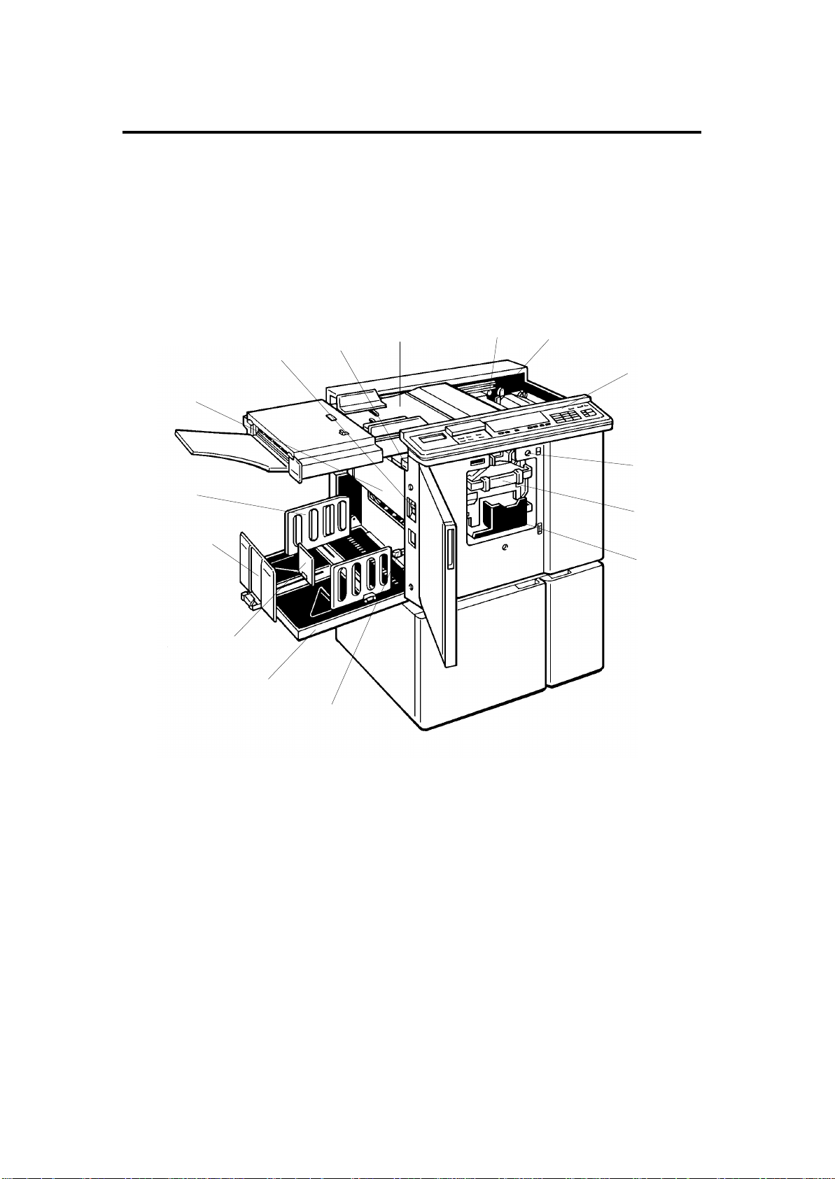
2. GUIDE TO COMPONENTS AND THEIR FUNCTION
7
8
9
10
11
12
6
13
5
14
4
15
3
2
1
1-5
Page 20

1 December 1993
No. Name Function
1. Wing Guide Release
Use to aid paper stack of large size paper.
Lever
2. Paper Delivery Table
3. Small Size Paper
Delivery End Plate
(for smaller than A4)
4. Paper Delivery End
Plate
(for larger than A4)
5. Paper Delivery Side
Plate
6. Master Eject Box
Cover
7. Main Switch
8. Master Eject Unit Open
Button
9. Original Table
10. Master Cut Button
Completed prints are delivered here.
Use to align the leading edge of prints that are
A4/LT or smaller.
Use to align the leading edge of prints larger
than A4/LT.
Use to align the prints on the paper delivery
table.
Open when removing the master eject box.
Use to turn the power on or off.
Press to remove misfed paper or a misfed
master.
Place the originals on this table.
Press this button to cut the master paper
leading edge after installing a new master roll.
11. Pressure Release
Lever
12. Operation Panel
13. Drum Rotation Button
14. Drum Unit
15. Ink Holder
Use to install the master roll, or to clean the
thermal head.
Operator controls and indicators are located
here.
Press to rotate the drum manually.
The master paper is wrapped around this unit.
Set the ink cartridge in this holder.
1-6
Page 21
1 December 1993
17
16
18
19
20
21
22
23
24
25
26
1-7
27
28
Page 22

1 December 1993
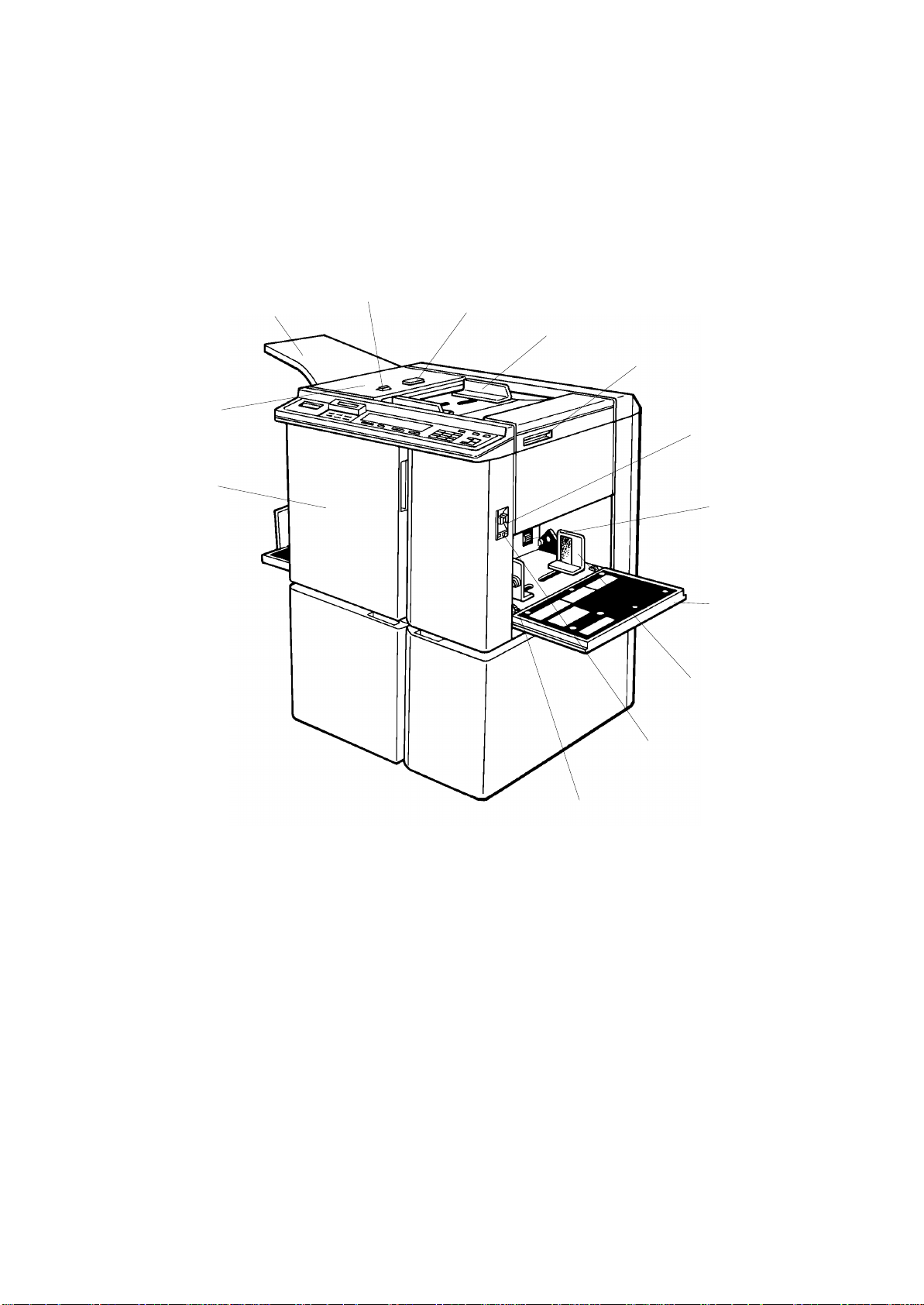
No. Name Function
16. Front Door
Open for access to the inside of the machine.
17. ADF Unit
18. Original Tray
19. ADF On/Off Select
Switch
20. ADF Unit Open Button
21. Original Guides
22. Original Table Release
Lever
23. Feed Roller Pressure
Lever
24. Separation Roller
Pressure Lever
25. Paper Table
Feeds the original to the scanning position
automatically.
Originals used to make master(s) are delivered
to this tray.
When setting originals one sheet at a time, set
this switch to the off position.
Use to open the ADF unit.
Adjust these guides to position the originals
correctly.
Use to open the original table unit to the left for
master installation.
Use to adjust the contact pressure of the paper
feed roller according to paper thickness.
Use to adjust the separation roller pressure to
prevent double feed.
Set paper on this table for printing.
26. Paper Feed Side Plate
27. Paper Table Down
Button
28. Side Registration Fine
Adjusting Dial
Use to prevent paper skew.
Press to lower the paper table.
Use to shift the paper table sideways.
1-8
Page 23
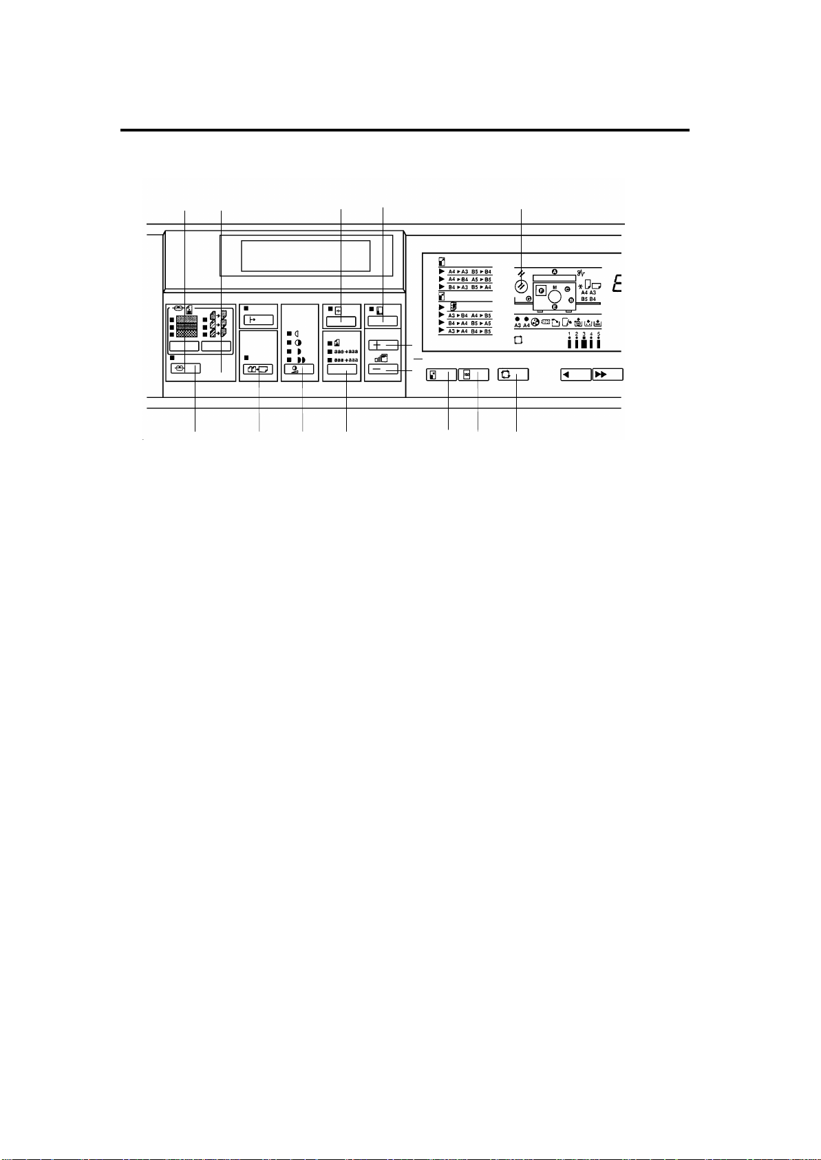
3. OPERATION PANEL
– Keys and Indicators –
1 December 1993
54
6789
1. Reset key
2. Directional
Magnification key
3. Image Shift key
32 1
10 11 12 13
Press to reset error indicators.
Press to enter the horizontal or vertical
magnification for copies, using the number keys.
Press to shift the image.
4. Contrast key
5. Screen key
6. Make Up key
7. Combine 2 Originals
key
8. Image Density key
9. Image Mode key
10. Zoom keys
11. Reduce/Enlarge key
12. Full Size key
13. Auto Cycle key
Press to select the desired contrast according to
the type and quality of the original.
Press to select the desired grade of screening to
be applied to the image according to the type and
quality of the original.
Press to use the make-up function.
Press to combine two originals onto one print
image.
Press to make prints darker or lighter.
Press to select line mode, photo mode or sharpen
image mode according to the type and quality of
the original.
Press to alter the reproductions ratio in 1%
increments from 50% to 200%.
Press to reduce or enlarge the image.
Press to make prints the same size as the original.
Use to automatically process masters and make
prints.
1-9
Page 24

1 December 1993
18
19 20
14. Clear Modes key
15. Program key
16. Enter key
17. Counter
17 16 15 14
22
21
Press to cancel all previously entered settings and
modes.
Press to input or recall user programs.
Press to input information into memory.
Displays the number of prints entered. While
printing, it shows the number of copies left to print.
232425
26
27 28
18. Monitors
19. Speed keys
20. Image Position key
21. Memory/Class
Indicators
22. Number keys
23. Memory/Class key
24. Clear key
25. Stop key
26. Proof key
27. Print Start key
Light or blink when a non-standard condition
occurs within the machine.
Press to adjust the rotation speed of the drum
according to the type of image and printing paper.
Press to shift the image forwards or backwards on
the print paper.
Shows the number entered in memory mode or
class mode.
Press to enter the number of prints.
Press to select group printing in memory mode or
class mode.
Press to change the number set in the counter.
Also use to change make-up mode. This key can
be used only after the machine stops operation.
Press to stop the machine operation. The machine
will continue operation when the Print Start key or
Master Making key is pressed.
Press to make trial prints or extra prints.
Press to start printing.
28. Master Making key
Press to make a master.
1-10
Page 25
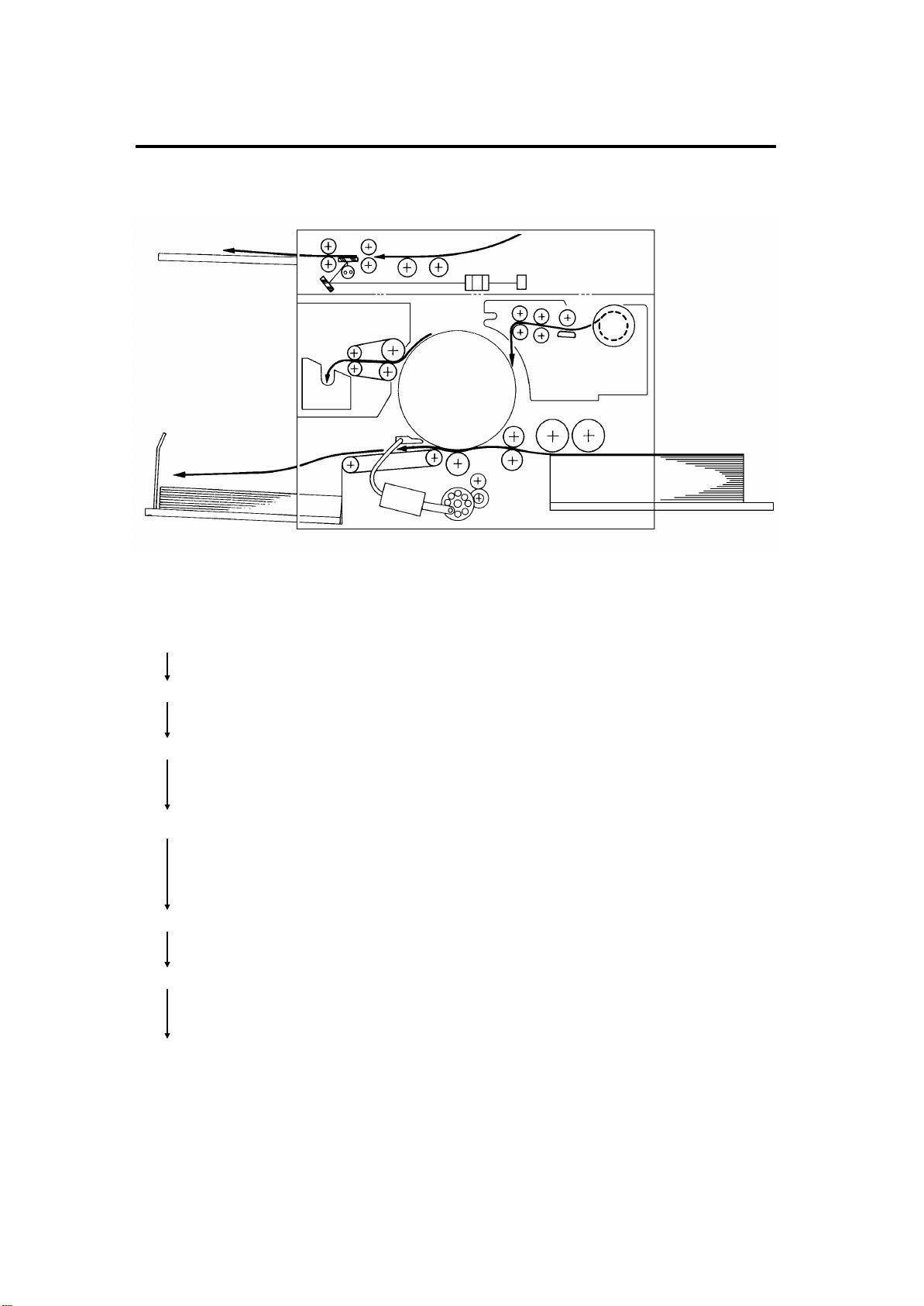
4. PRINTING PROCESS
1
1 December 1993
23
4
7
6
5
1. Master Ejecting: Ejects the used master wrapped around the
drum into the master eject box.
2. Original Feeding: Transports the original to the scanner section.
3. Scanning: Scans the original image with the CCD through
the mirror and the lens while feeding the
original.
4. Master Feeding: Converts the image signal read by the CCD into
digital signals and sends them to the thermal
head to plot holes on the master. The master
then wraps dround the drum.
5. Paper Feeding: Sends paper separately to the drum section.
6. Printing: Presses the paper fed from the paper feed
section to the drum. This transfers the ink to the
print through the drum screen and the master.
7. Paper Delivering: Peels the printed paper with the exit pawl and
air knife and ejects the paper onto the paper
delivery table.
1-11
Page 26
1 December 1993
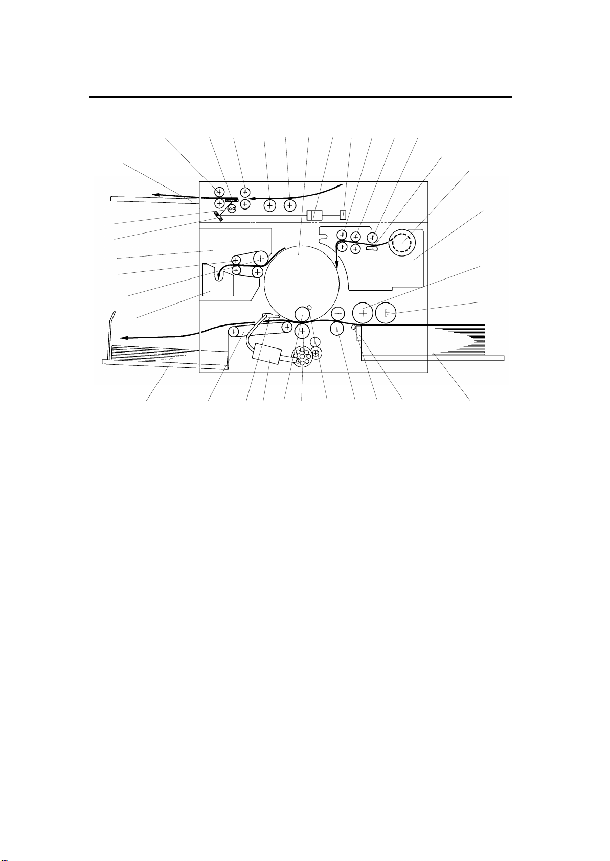
5. MECHANICAL COMPONENT LAYOUT
123456
3433323130
28
27
26
25
29
24
23
19
7
8
9
10
11
13
18202122
17
141516
12
1. Drum Unit
2. Lens
3. CCD
4. Reverse Roller
5. Master Feed Roller
6. Platen Roller
7. Thermal Head
8. Master Roll
9. Plotter Unit
10. Upper Separation Roller
11. Paper Feed Roller
12. Paper Table
13. Separation Plate
14. Lower Separation Roller
15. 2nd Feed Roller
16. Doctor Roller
17. Press Roller
18. Ink Roller
19. Paper Exit Pawl Air Pump
20. Paper Exit Pawl
21. Transport Unit
22. Paper Delivery Table
23. Master Eject Box
24. 1st Eject Roller
25. 2nd Eject Roller
26. Master Eject Unit
27. Mirror
28. Fluorescent Lamp
29. Original Exit Tray
30. 2nd Original Transport Roller
31. Exposure Glass
32. 1st Original Transport Roller
33. Original Feed Roller
34. Pull-out Roller
1-12
Page 27
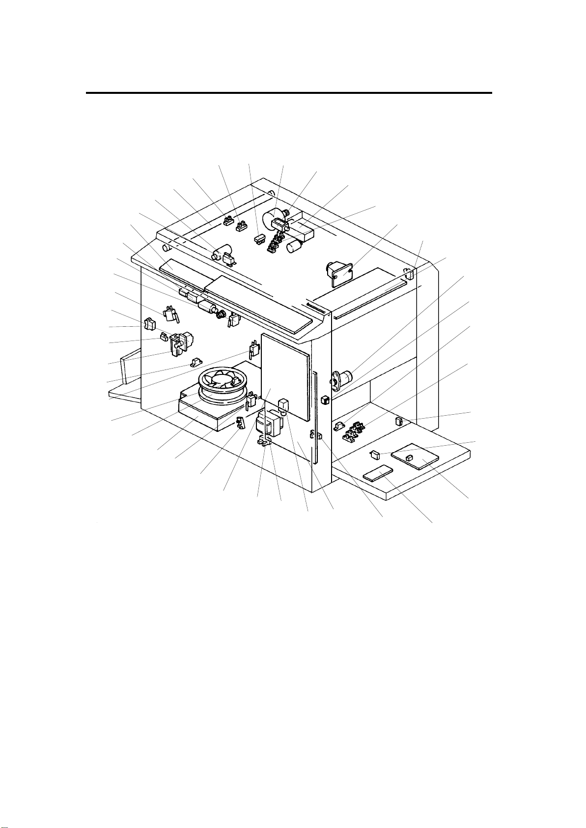
6. ELECTRICAL COMPONENT LAYOUT
1 December 1993
2
1
43
42
41
40
39
38
37
36
35
34
33
32
31
30
29
28
27
26
34
5
6
7
8
9
10
11
12
13
14
15
16
25
24
23
22
1-13
21
20
19
17
18
Page 28

1 December 1993
1. Original Registration Sensor
2. 2nd Original Sensor
3. 1st Original Sensor
4. Original Transport Motor
5. Original Pressure Solenoid
6. Fluorescent Lamp Stabilizer
7. Original Width Sensor
8. CCD PCB
9. Scanner Unit Safety Switch
10. A/D Conversion PCB
11. Paper Return Motor
12. Paper Table Down Button
13. Paper End Sensor
14. Paper Width Sensor
22. Transformer
23. Paper Table Lower Limit Sensor
24. Main PCB
25. Printing Pressure Sensor
26. Front Door Safety Switch
27. Power Supply Unit
28. Vacuum Fan Motor
29. 1st Paper Exit Sensor
30. Drum Detection Switch
31. 2nd Paper Exit Sensor
32. Circuit Breaker
33. Delivery Table Open Switch
34. Main Switch
35. Interlock Switch
15. Paper Table Open Switch
16. Paper Table Safety Switch
17. Paper Detection PCB
(Paper Length Sensor)
18. Cassette Size Detection PCB
19. Paper Table Height Sensor
20. Image Processing PCB
21. Separation Plate Release
Solenoid
36. Air Knife Motor Safety Switch
37. Drum Rotation Switch
38. Drum Rotation LED
39. Total Counter
40. Operation Panel
41. ADF Safety Switch
42. ADF Drive Motor
43. Fluorescent Lamp
1-14
Page 29
1 December 1993
58
57
56
59
55
54
53
60
52
61
63
64
62
44
45
46
47
51
50
49
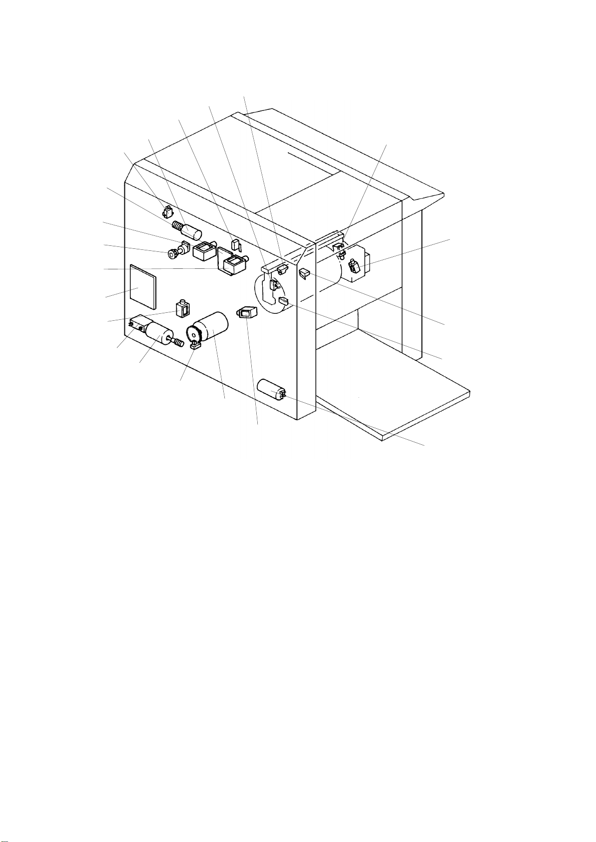
44. Ink Supply Solenoid
45. Drum Lock Solenoid
46. Master Eject Unit Safety Switch
47. 2nd Drum Position Sensor
48. Noise Filter
49. Printing Pressure Solenoid
50. Main Motor
51. Drum Rotation Sensor
(Pulse Generator)
52. Paper Table Drive Motor
53. Paper Table Drive Motor
Capacitor
48
54. Paper Feed Solenoid
55. AC Drive PCB
56. Master Eject Clamper Solenoid
57. Image Position Sensor
58. Master Feed Clamper Solenoid
59. Ink Detection PCB
60. Master Cut Button
61. Image Positioning Motor
62. Drum Unit Safety Switch
63. 1st Drum Position Sensor
64. Drum Master Detection Sensor
1-15
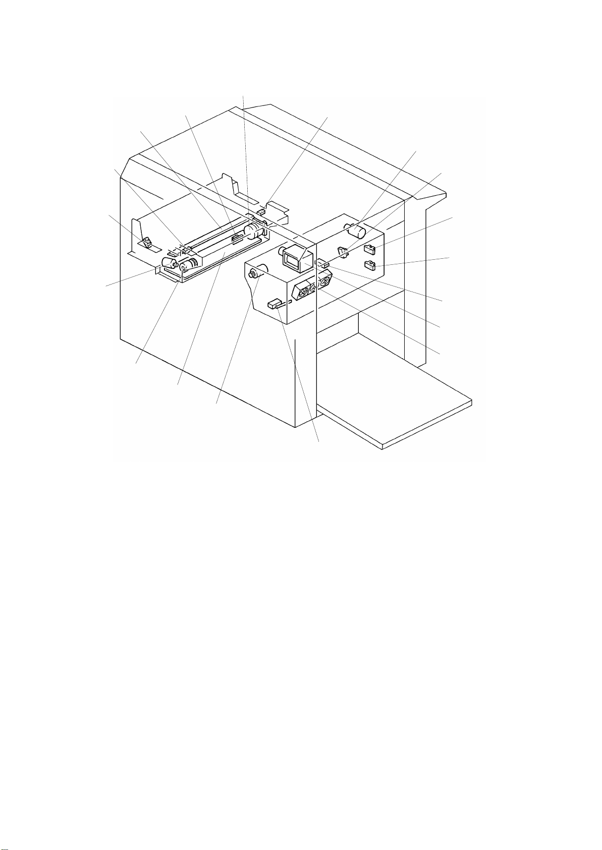
Page 30
1 December 1993
77
76
78
79
75
74
80
81
82
65
66
67
68
69
70
71
73
65. Pressure Plate Motor
66. Lower Pressure Plate Sensor
67. Upper Pressure Plate Sensor
68. Full Master Detection Sensor
69. Master Eject Sensor
70. Master Eject Solenoid
71. Air Knife Motors
72. Master Eject Box Switch
73. Master Eject Motor
74. Thermal Head Drive PCB
72
75. Reverse Roller Magnetic Clutch
76. Cutter Motor
77. Master End Sensor
78. Right Cutter Switch
79. Thermal Head
80. Master Buckle Sensor
81. Master Feed Motor
82. Left Cutter Switch
1-16
Page 31

1 December 1993
7. ELECTRICAL COMPONENT DESCRIPTIONS
Index No. Name Function
Motors
4 Original Transport
Motor
11 Paper Return Motor Returns paper to the paper table when
28 Vacuum Fan Motor Provides suction so paper is held firmly
42 ADF Drive Motor Feeds the original to the scanner
50 Main Motor Drives paper feed, drum, printing and
Transports the original to the scanner
section.
the paper table is lowered.
on the transport belt.
section.
paper delivery unit components.
52 Paper Table Drive
Motor
61 Image Positioning
Motor
65 Pressure Plate Motor Raises and lowers the pressure plate.
71 Air Knife Motors Rotates the fan to separate the paper
73 Master Eject Motor Sends used master into the master
76 Cutter Motor Cuts the master.
81 Master Feed Motor Feeds the master to the drum.
Solenoids
5 Original Pressure
Solenoid
21 Separation Plate
Release Solenoid
44 Ink Supply Solenoid Releases the spring clutch to turn on
Raises and lowers the paper table.
Changes the timing between the paper
feed roller and the drum to adjust the
vertical image position.
leading edge from the drum.
eject box.
Presses the original pressure plate
down on the originals.
Releases the separation plate when the
paper table is lowered.
activate the ink supply pump.
45 Drum Lock Solenoid P revents the drum unit from being
removed during the printing run.
49 Printing Pressure
Solenoid
54 Paper Feed Solenoid Releases the sector gears to feed the
Engages the pressure ON/OFF lever
when a paper misfeed occurs.
paper.
1-17
Page 32

1 December 1993
Index No. Name Function
56 Master Eject
Clamper Solenoid
58 Master Feed
Clamper Solenoid
Opens the master clamper to eject the
master.
Opens the master clamper to clamp the
master.
70 Master Eject Solenoid Presses the lower master eject roller
against the drum surface.
Sensors
1 Original Registration
Sensor
Informs the CPU when the original
activates the sensor. Also, detects the
original misfeed.
2 2nd Original Sensor Informs the CPU when the original
activates the sensor. Also, detects
original misfeeds.
3 1st Original Sensor Informs the CPU if the original is set in
the ADF mode.
7 Original Width Sensor Informs the CPU of the original width.
13 Paper End Sensor Informs the CPU if the paper is set on
the paper table.
14 Paper Width Sensor Informs the CPU of the paper width.
19 Paper Table Height
Sensor
23 Paper Table Lower
Limit Sensor
25 Printing Pressure
Sensor
Informs the CPU if the paper table is at
the paper feed position.
Informs the CPU if the paper table is at
the lowest position.
Informs the CPU if printing pressure is
applied. Also, detects paper misfeeds.
29 1st Paper Exit Sensor Detects paper misfeeds.
31 2nd Paper Exit
Detects paper misfeeds.
Sensor
47 2nd Drum Position
Checks the position of the drum.
Sensor
51 Drum Rotation
Sensor
57 Image Position
Supplies timing pulses to the CPU
based on the main motor speed.
Informs the CPU of the image position.
Sensor
63 1st Drum Position
Checks the position of the drum.
Sensor
1-18
Page 33

Index No. Name Function
64 Drum Master
Detection Sensor
66 Lower Pressure
Plate Sensor
67 Upper Pressure
Plate Sensor
Informs the CPU if the master is on the
drum.
Informs the CPU if the pressure plate is
at the lower limit position.
Informs the CPU if the pressure plate is
at the upper limit position.
1 December 1993
68 Full Master Detection
Sensor
Informs the CPU when the master eject
box is full of masters.
69 Master Eject Sensor Detects used master misfeeds.
77 Master End Sensor Informs the CPU if the plotter unit runs
out of master roll.
80 Master Buckle
Sensor
Informs the CPU if the master is
buckling.
Switches
9 Scanner Unit Safety
Switch
Cuts off the power line of the main and
paper table drive motors when the
scanner unit is open.
12 Paper Table Down
Button
Informs the CPU to turn on the paper
table drive motor to lower the paper
table.
15 Paper Table Open
Switch
16 Paper Table Safety
Switch
Checks whether the paper table is
opened correctly or not.
Stops lowering the paper table to
prevent catching fingers under it. Cuts
the AC power line.
26 Front Door Safety
Switch
Cuts off the power line of the paper
table drive motor when the front door is
open.
30 Drum Detection
Switch
Checks whether the drum unit is set
correctly or not.
33 Delivery Table Open
Switch
Checks whether the delivery table is
opened correctly or not.
34 Main Switch Turns the power on or off.
35 Interlock Switch Disables the front door, paper table,
master eject unit, and scanner unit
safety switches.
36 Air Knife Motor
Safety Switch
Cuts off the power line of the paper
table drive motor when the master eject
unit is open.
1-19
Page 34

1 December 1993
Index No. Name Function
37 Drum Rotation Switch Informs the CPU to rotate the drum at
10 rpm.
41 ADF Safety Switch Cuts the power line of the paper table
drive motor off when the ADF is open.
46 Master Eject Unit
Safety Switch
Cuts off the power line of the paper
table drive motor when the master eject
unit is open. (Also, cuts off the power
line of the main motor in the 220/240 V
version machines.)
60 Master Cut Button Informs the CPU to cut the master
paper leading edge.
62 Drum Unit Safety
Switch
72 Master Eject Box
Switch
Checks whether the drum unit is set
correctly or not.
Checks whether the master eject box is
set correctly.
78 Right Cutter Switch Detects when the cutter position is far
right (non-operation side).
82 Left Cutter Switch Detects when the cutter position is far
left (operation side).
Printed Circuit Board
8 CCD PCB Converts light intensity into an electrical
signal.
10 A/D Conversion PCB Converts the analog signal into a digital
signal.
17 Paper Detection PCB Detects the size of the paper set on the
table.
18 Cassette Size
Detection PCB
20 Image Processing
PCB
Detects the size of the cassette set on
the table.
Controls the image processing
performance.
24 Main PCB Controls all machine functions both
directly and through other boards.
55 AC Drive PCB Controls the AC component by relays.
59 Ink Detection PCB Controls the ink supply.
74 Thermal Head Drive
PCB
Supplies the power to the thermal head
according to the signal from the
scanner section.
1-20
Page 35

1 December 1993
Index No. Name Function
Counters
39 Total Counter Keeps track of the total number of
prints made.
Others
6 Fluorescent Lamp
Stabilizer
Stabilizes the power supplement to the
fluorescent lamp.
22 Transformer Steps down the wall voltage.
27 Power Supply Unit Provides power for all DC components.
32 Circuit Breaker Cuts the AC line off.
38 Drum Rotation LED Turns to green from red when the drum
stops to the home position.
43 Fluorescent Lamp Applies light to the original for exposure.
48 Noise Filter Fi lters electrical noise on the AC power
input lines.
53 Paper Table Drive
Motor Capacitor
75 Reverse Roller
Magnetic Clutch
Protects the AC drive PCB from
induced current.
Stops the reverse roller turning while
the master buckle sensor is OFF.
79 Thermal Head Plots the master using heat.
1-21
Page 36

1 December 1993
8. DRIVE LAYOUT
20
19
18
17
16
21
3
4
5
6
7
8
9
15 14 13 12 11
1. Reverse Roller Gear
2. Image Position Motor
3. Original Transport Motor
4. Master Eject Motor
5. Drum Drive Gear
6. Drum Unit Gear
7. Drum Drive Pulley
8. Main Drive Belt
9. Transport Belt
10. Printing Pressure Pulley
10
11. Printing Pressure Gear
12. Idle Gear
13. Idle Pulley
14. Main Motor
15. Paper Table Drive Motor
16. Paper Feed Cam Gear
17. Master Feed Motor
18. Timing Belt
19. Platen Roller Gear
20. Master Transport Roller Gear
1-22
Page 37

SECTION 2
SECTIONAL DESCRIPTION
Page 38

1 December 1993
1. MASTER EJECT SECTION
1.1 OVERALL
At the end of the printing cycle, the used master remains wrapped around the
drum to prevent the ink on the drum surface from drying. When the Master
Making key is pressed to make a new master, the used master is ejected
from the drum.
The master is pulled off the drum, then it goes through the eject rollers and
into the master eject box. A pressure plate then compacts the used master.
[D]
[G]
[C]
[A]
[F]
Drum
[E]
[B]
•
Drum [B] rotates in reverse
(opposite to printing direction).
•
Master eject rollers [A] rotate.
•
Lower eject roller [C] is pressed
against the drum.
•
The trailing edge of the master
curls off the drum and passes
between the upper [E] and lower
[F] eject rollers, and the master [D]
is dumped into the master eject
box [G ].
[H]
•
The pressure plate [H] compacts
the ejected master [I].
[I]
2-2
Page 39

1 December 1993
1.2 MASTER EJECT ROLLER ROTATING MECHANISM
[I]
[J]
[H]
[G]
[A]
[B]
[E]
[F]
[B]
[C]
[D]
[E]
[F]
When the original is set and the Master Making key is pressed, the main
motor starts turning at 30 rpm in reverse. So now the drum also turns in
reverse (compared with the printing rotations).
At this time, if the drum master detection sensor detects a master on the
drum, the master eject motor [A] starts rotating. Drive is transmitted to gear
[E] and to the upper first eject rollers [G] through the timing belt [B] and gears
[C] and [D]. Gear [F] drives the lower first eject rollers [H]. The belts [I]
transmit drive from the first eject rollers to the upper and lower second feed
rollers [J].
(If the drum master detection sensor detects no master on the drum when the
Master Making key is pressed, the machine skips the master eject process
and goes directly to the master making process.)
After the master eject process is completed, the drum returns to its home
position. The master eject rollers then stop rotating.
This model has five rollers on each eject roller shaft. The roller shafts can
feed up to A3/DLT sized masters.
2-3
Page 40

1 December 1993
1.3 MASTER EJECT ROLLER DRIVE MECHANISM
[H]
[G]
[A]
[B]
[C]
[D]
[E]
[F]
The drum position is detected by the first [G] and second [H] drum position
sensors. When the drum reaches its home position, the first drum position
sensor [G] is activated by the interrupter [F] at the rear side of the drum.
To eject the master, the drum turns in reverse (opposite to the printing
direction). When the A3/DLT drum is 70° from the home position, the master
eject solenoid [A] turns on and the supporter [C] rotates counterclockwise on
the upper eject roller shaft [D]. This forces the lower first eject roller [E]
against the drum.
As the drum turns, the curled trailing edge of the master [B] passes between
the upper and lower first eject rollers. The first eject rollers then peel the
master from the drum.
2-4
Page 41

1 December 1993
[A]
[B]
[C]
[D]
When the A3/DLT drum is 109 degrees from the home position, the master
eject solenoid [A] turns off, separating the lower first eject rollers [C] from the
drum.
When the ejected master passes between the upper and lower first eject
rollers, the master eject sensor [B] is actuated. The master is then dumped
into the master eject box [D].
2-5
Page 42

1 December 1993
Print key on
First Drum Position Sensor
Master Eject Solenoid
Sensor ON Check
70°
Drum Rotation
Reverse Reverse
Master Eject Sensor
Master Eject Motor
Misfeed Indic at or Light s
39° 18°
50° 50°
68°
Foward
[Master Eject Misfeed Detection]
The misfeed indicator for the master eject section blinks in the following
cases:
Case 1: The master eject sensor is not activated and the drum has turned
50 degrees more (still in reverse and after de-activation of the
master eject solenoid). The machine knows that the eject rollers
have failed to catch the master. So the drum returns 68 degrees (in
the printing direction) to repeat the master eject process once
again. The master eject solenoid is again energized while the drum
turns another 18 degrees to try to catch the master.
If the master eject sensor once again fails to detect the master,
then the drum returns to its home position and the misfeed
indicator blinks.
Case 2: The drum finishes its rotation for the master ejecting process and
retuns to the home position, but the master eject sensor does not
turn off. This means that the master is still in between the master
eject rollers, the misfeed indicator blinks.
2-6
Page 43

1.4 MASTER EJECT CLAMPER MECHANISM
[G]
[F]
1 December 1993
[B]
[A]
[C]
[D]
[E]
When the drum rotates 306 degrees (in reverse) past the home position, the
master eject clamper solenoid [A] turns on and lever [B] rotates
counterclockwise as shown. This moves the cam [D] inside the drum. Drum
rotation brings the clamper sector gear [E] against the cam [D]. Gear [F] turns
counterclockwise as it engages the clamper sector gear, thus opening the
master clamper [G]. This releases the master from the drum.
The drum keeps on turning until the interrupter at the rear side of the drum
goes 13 degrees past the first drum position sensor. Then, the main motor
turns off. Half a second later, the master eject clamper solenoid [A] turns off
and spring [C] pulls cam [D] back to its initial position. The drum then rotates
forward to its home position.
2-7
Page 44

1 December 1993
1.5 PRESSURE PLATE UP/DOWN MECHANISM
[B]
[M]
[C]
[L]
[D]
[A]
[K]
[E]
[F]
[G]
[I]
[H]
[J]
[Pressure Plate Down]
When the interrupter at the rear side of the drum interrupts the first drum
position sensor (this means the end of the master eject process), the
pressure plate motor [B] starts rotating. This drives gear [H] clockwise by
means of gears [C], [D], [E], and [F].
Pin [I] on gear [H] moves link [G] down until the link interrupter [L] interrupts
the lower pressure plate sensor [J]. Spring [M] pulls down on the pressure
plate and the ejected master in the master eject box is compressed by the
pressure plate [A].
If the full master detection sensor [K] does not turn on when the pressure
plate goes down, it means the master eject box is filled with ejected masters.
In this case, the Master Full indicator blinks, and the machine stops after a
new master is wrapped around the drum.
Reset the Master Full indicator by turning the Master Eject Box switch OFF
and ON. This is to prevent the master full indicator from being reset without
removing the ejected masters from the box. When the Master Full indicator is
blinking, the Master Making key does not work, but the Print Start key and
Proof key work.
2-8
Page 45

1 December 1993
[A]
[B]
[G]
[C]
[F]
[D]
[E]
[Pressure Plate Up]
When the master has been wrapped around the drum in the master making
process and the master cutter leaves the home position to cut the master, the
pressure plate motor [B] starts rotating to raise the pressure plate.
When the pressure plate motor [B] turns, the gear [C] is driven through the
relay gears. The pin [F] on the gear inserted into the link [D] rises and lifts the
left end of the link, thus raising the pressure plate.
The gear [C] continues turning until the interrupter [G], installed in the front
end of the pressure plate, blocks the upper pressure plate sensor [A]. At this
time, the master eject motor [B] stops and the pressure plate is held in the
upper position.
[Pressure Plate Motor Lock Detection]
To prevent the pressure plate motor from locking, "E-12" lights up on the
operation display panel under the following conditions:
1. The upper [A] or lower [E] pressure plate sensor remains activated for
more than 4 seconds after the pressure plate motor starts turning.
2. The lower pressure plate sensor [E] is not activated within 8 seconds of
the pressure plate motor starts turning even though the upper pressure
plate sensor [A] is de-activated.
3. The upper pressure plate sensor [A] is not activated within 8 seconds of
the pressure plate motor starts turning even though the lower pressure
plate sensor [E] is de-activated.
2-9
Page 46

1 December 1993
1.6 ELECTRICAL TIMING
T1
First Drum Position Sens or
Second Drum Position Sensor
Main Motor Reversing
30 rpm
Main Motor Forwarding
Master Eject Motor
T2
Master Eject Solenoid
Master Eject Clamper Solenoid
X1
306°
T1: When the Master Making key is
pressed, the main motor and
master eject motor start turning. At
the same time, the paper table drive
motor starts turning to lift the paper
table to the paper feed position.
T2: When the drum rotates X1 degrees
past the first drum position sensor
actuation position (drum home
position), the master eject solenoid
is energized. This presses the lower
eject rollers against the drum
surface. The master eject solenoid
is de-energized when the drum
rotates X2 degrees more.
X2
T4
13°
30 rpm
T3
500 msec
0°
0°
70°
39°
The drum rotation angles X1 and
X2 depend on the drum type. This
machine has two types of drums:
one is the A3/DLT drum (standard),
and the other is the A4/LT drum
(optional). X1 and X2 for each drum
are as follows:
Drum Type A3/DLT A4/LT
X1 (degree) 70 137
X2 (degree) 39 50
2-10
Page 47

1 December 1993
T3: When the drum rotates 306
degrees past the home position, the
master eject clamper solenoid is
energized.
T4: When the drum rotates 13 degrees
past the drum home position, the
drum stops rotating.
500 milliseconds later (the drum
completely stops during this period),
the master eject clamper solenoid is
de-energized and the drum starts
rotating forward. The drum then
returns to its home position. The
master eject process is now over.
Soon after this, the machine starts
feeding a new master and the drum
starts rotating in reverse to begin
the master making process.
13°
0°
306°
0°
2-11
Page 48

1 December 1993
-24
-23
-22
-27
-26
-25
-30
-29
-28
-17
-16
-19
-18
0V
0V
0V
Main PCB
5V
GND
5V
GND
5V
GND
5V
LED DRIVE
5V
5V
CN103
-21
24V
24V
FU101
FU102
GND
-10
-20
-11
-19
-12
-25
-6
CN101
-20
-21
SOL
M
M
SOL
plate is at the hi ghest position.
5V
plate is at the lowest position.
5V
of the pressure pla te passes through
the sensor. (M ast er fu l l det ect i on in the
[E]
[F]
[G]
[H]
[I]
1.7 CIRCUIT
[A]
[B]
[C]
[D]
Component
Name
Upper Pressure
Plate Sensor [A]
Lower Pressure
Plate Sensor [B]
Full Master
Detection
Sensor [C]
CN101
1
2
3
1
2
3
1
2
3
In/Ou t Main P C B Description
CN No. Signal Level
In 101-23 Signal goes High when t he pr essure
In 101-26 Signal goes High when t he pr essure
In 101-29 Signal goes High when t he i nter r upt er
master eject box.)
Master Eject
Sensor [D]
Sensor LED [D] Out 101-16 Pulse signal goes to Low and the LED
Master Eject
Solenoid [E]
Master Eject
Motor [F]
Pressure Plate
Motor [G]
Master Eject
Clamper
In TP104 Signal goes High when the sensor
0V
3 msec
5V
3.5V
Out 103-10 Signal goes Low when the soleno i d
Out 103-11 Signal goes Low when the motor turn s
Out 103-12 Signal goes Low when the motor turn s
Out 103-6 Signal goes Low when the solenoid
24V
24V
24V
24V
3V
detects the master. This is a pulse
signal.
lights when the main switch is turned on.
600
sec
µ
0V
turns on.
0V
on.
0V
on.
turns on.
0V
Solenoid [H]
Master Eject
Box Switch [I]
In 101-20 Signal goes Low when the m aster eject
5V
0V
box is installed.
2-12
Page 49

2. SCANNER/OPTICS SECTION
2.1 OVERALL
1 December 1993
[A]
[G]
Thermal Head
[F]
[E]
Thermal Head
Drive PCB
Operation Panel
PCB
[D]
[B]
[C]
A/D Conversion
PCB
Image Proccessing
PCB
Main PCB
The first original [A] at the bottom of the stack on the original table is
separated from the other originals by the original feed rollers [E] and the
separation blade [B], and is fed onto the exposure glass [F].
The light of the fluorescent lamp [G] is reflected from the original and goes
through the lens [D]. The light is changed to an electrical signal in the CCD
(Charge Coupled Device) [C].
The electrical signal from the CCD is converted into an 8-bit digital signal in
the A/D conversion PCB. Then the upper 6 bits of the 8 bits are used in the
image processing PCB.
The binary circuit in the image processing PCB produces 1-bit data (white or
black) from the 6-bit data and sends it to the thermal head dri ve PCB.
The thermal head plots image data on the master and is driven through the
thermal head drive PCB.
2-13
Page 50

1 December 1993
[A]
[B]
[C]
[F]
[D]
[E]
[Light Source]
A high frequency (15 kHz) fluorescent lamp [D] is used as a light source for
high speed reading. The light is reflected at two angles using a mirror [F].
This prevents shadows from the edges of cut-and-paste originals from
appearing on the original [B]. The original guide plate [C] blocks part of the
direct light from the fluorescent lamp to make the light intensity of both the
direct light and reflected light the same. A heater [E] is wrapped around the
fluorescent lamp. The lamp stays on for one minute when the main switch is
turned on to quickly raise the lamp temperature. This prevents a loss in light
intensity that would occur if the temperature were too low.
[Platen Cover]
The CCD reads the platen cover [A] to obtain a standard white level before
the original is read. The standard white data are used to correct for distortion
such as bright or dull spots in the light path (lamp, reflectors, exposure glass,
mirrors, lens, and CCD).
2-14
Page 51

1 December 1993
Fluorescent
Lamp
CN608
-1
[D]
-2
-3
[C]
-4
Original
Scanning
Signal
Main PCB
CN601
-A13
+5V
+24V
4.3K
TH601
110K
[B]
[A]
24K
A/D Conversion PCB
Q605
10K
5
6
18K
+
7
_
IC
Q602
[Lamp Heater]
The thermistor [C] mounted in the lamp heater maintains the lamp
temperature at about 40°C.
Lamp
Heater
If the lamp temperature drops too low, the voltage at [B] goes High. This is
because the resistance of thermistor [C] increases, causing the voltage at
IC-pin 7 (operational amplifier) to go High. Q602 then turns on and the lamp
heater [D] is energized. If the lamp temperature rises, the voltage at [B]
becomes less than that at IC-pin 6. This causes IC-pin 7 to go Low, which
turns off the lamp heater.
Thermistor TH601 in the A/D conversion PCB monitors the temperature
inside the machine. If the temperature is low, the increased resistance of
TH601 drops the voltage at [A] and the control temperature of the heater
thermistor (heater ON/OFF temperature) is raised slightly. If the temperature
is high, the control temperature is lowered slightly.
If Q605 turns on, the voltage at [B] becomes 0 volt and the lamp heater turns
off. Q605 is turned on when the original scanning signal (active low) is sent
from the main PCB. Consequently, the heater is always off during the original
scanning process.
2-15
Page 52

1 December 1993
[A]
[B]
[C]
[Lens]
The lens assembly [B] consists of 6 lenses to transfer the image to the
photoelectric elements of the CCD. It is possible to adjust the focus by
moving the lens assembly.
[Shading Plate]
Compared with the ends, the middle of the lamp is too bright. To correct this,
a shading plate [A] is placed in front of the lens. This blocks some of the light
and distributes it more uniformly.
[CCD (Charge Coupled Device)]
The CCD [C] is a solid-state device similar to a photodiode array, but unlike a
photodiode array, a CCD can read one complete scan line at a time. The
CCD produces an analog signal which is converted into a digital signal in the
A/D conversion PCB.
2-16
Page 53

2.2 ORIGINAL FEED MECHANISM
1 December 1993
[A]
[C]
[B]
[D]
[E]
[L]
[F]
[K]
[I]
[H]
[G]
[J]
[J]: Fluorescent Lamp
[K]: Exposure Glass
[L]: 2nd Original Transport Rollers
Two original feed modes can be selected by the ADF ON/OFF select switch.
[ADF Mode]
The originals [A] set on the original table are detected by the 1st original
sensor [E]. When the Master Making key is pressed, the original pressure
plate [D] presses the originals down. The pull-out rollers [F] start moving the
lowest original forward at the same time. The lowest original is separated
from the other originals by the original feed rollers [G] and the separation
blade [C].
350 milliseconds after the 2nd original sensor [H] detects the original, the 1st
original transport rollers [B] start rotating. The rollers stop after the original
activates the original registration sensor [I]. The 1st original transport rollers
start rotating again after the drum section completes the preparation for the
master making.
[SADF Mode]
The separation blade [C] and the original pressure plate [D] are released in
the SADF mode. The original on the original table is fed to the original
reading position one second after the 2nd original sensor [H] detects the
original.
[Original Misfeed Detection]
The original misfeed indicator blinks in the following conditions:
1. The 2nd original sensor is not activated within 3 seconds after the ADF
drive motor turns on.
2. The original registration sensor is not activated within 3.5 seconds after
the 2nd original sensor is activated.
2-17
Page 54

1 December 1993
2.3 ORIGINAL FEED DRIVE MECHANISM
[A]
[L]
[K]
[J]
[I]
[H]
[G]
[B]
[C]
[D]
[E]
[F]
[M]
[N]
[M]
[B]
[O]
[P]
[E][B]
[E]
The original transport rollers [A] are driven by the original transport motor [C],
which is a stepper motor. The original feed rollers [B] are driven by the ADF
drive motor [F] (dc motor) through a series of gears [G] to [L]. The pull-out
rollers [E] are driven by the ADF motor through a drive belt [D].
The original pressure plate [P] is pressed down on the originals by the
original pressure solenoid [O]. The separation blade [M] is moved up and
down by the ADF ON/OFF select switch [N].
2-18
Page 55

2.4 ORIGINAL SIZE DETECTION
1 December 1993
[F]
[E]
[D]
[C]
[A]
[B]
[A]
[B]
The original width detection plate [A] installed behind the rear original guide
[B] has 4 photointerrupters.
The front and rear original guides are adjusted according to the original width.
Depending on which original size sensors are interrupted, the machine
determines the original width as shown in the below table. The original size
sensors are 4 photointerrupters.
Original Size* A3 DLT B4 LT/LG A4 B5 A5 HLT
Original Size Sensor - 3 [C] o x o x x o x x o
Original Size Sensor - 2 [D] x o o x x o o o o
Original Size Sensor - 1 [E] x x o o o o x x x
Original Size Sensor - 0 [F] x x x x o o o o o
x: Non-blocked, o: Blocked
* All of the above original sizes are for lengthwise feed.
2-19
Page 56

1 December 1993
The machine also checks the paper size on the paper feed table (both the
length and width).
When the paper width is smaller than the original width (multiplied by the
reproduction ratio), the machine indicates "Check paper size" on the
operation display for 3 seconds when the Master Making key is pressed. If
the operator ignores the indication and presses the Master Making key again,
the machine goes ahead with normal processing.
If the original size is different from the paper size, the machine compares the
length of the original and paper. The master’s length will be the shorter of the
two. The machine runs the same procedure for the width. (The original length
is detected by scanning the original.)
2-20
Page 57

2.5 ELECTRICAL TIMING
1 December 1993
First Drum Positi on
Sensor
Second Drum Position
Sensor
First Original Sensor
Master Motor Key
Main Motor Reversing
Lamp On Signal
ADF Drive Motor
Original Pressure
Solenoid
Second Original Sensor
Original Registration
Sensor
Original Transport Motor
T1
Master Eject Process Master Making Process
T2
218.5° in Drum R otation
350 msec
T3
T4
T5
15 mm
15.5 mm 20.5 mm
T6
High
Speed
Master Feed Motor
Original Scanni ng Sig nal
410 mm (Max.)
Master Plotting Signal
Plotting Signal
Start Position
10 mm
15.5 mm
Scanning Signal
Start Position
16 mm
15 mm
4.5 mm
Original
Guide P late
Exposure Glass
CCD Scan Line
Original Registration
Sensor
T1: When originals are inserted in the ADF unit, the first original sensor is
activated.
2-21
Page 58

1 December 1993
T2: When the Master Making key is pressed, the ADF drive motor starts
rotating and the lowest original in the ADF unit is fed. At the same time,
the original pressure solenoid is energized and the pressure plate
presses the originals against the pull-out rollers. The fluorescent lamp
lights about 3 milliseconds after the lamp on signal turns on.
T3: The original transport motor starts rotating and turns the transport rollers.
This happens 350 milliseconds after the second original sensor is
activated.
T4: The original transport motor stops rotating when the original is fed 15
millimeters past the original registration sensor actuation position. The
leading edge of the original is stopped 5.5 millimeters before the scanning
position. (See illustration on the previous page.)
T5: After the master eject process is finished, the drum rotates 218.5 degrees
more (in reverse) past the second drum position sensor actuation position
and stops at the master clamping position.
When the drum stops, the original starts being fed and the original
scanning starts. Since there is a 5.5 millimeter distance until the leading
edge of the original reaches the scanning position, the CCD reads the
platen cover as a standard white level during this period.
After the original is fed 15.5 millimeters, the master starts being fed and is
plotted by the thermal head. At this time, the master has a 10 millimeters
blank margin at its leading edge.
T6: When the original scanning for the plotting area is finished, the master
plotting signal is de-energized and the thermal head turns off. At the
same time, the original transport motor speeds up (about 4 times) and
spits out the original.
The plotting area of the master depends on whether the paper size or
original size is smaller. If the original length is shorter than the paper
length, then scanning finishes 20.5 millimeters after the trailing edge of
the original has passed the original registration sensor.
If the paper length is the same or shorter than the original, scanning
finishes when the master has been fed the length of the paper. For the
A3/DLT drum, the master is fed 410 millimeters, at most, and for the
A4/LT drum, the master is fed a maximum of 206 millimeters.
2-22
Page 59

[Electrical Timing for SADF Mode]
1 December 1993
First Original Sensor
Master Making Key
Lamp On Signal
ADF Drive Motor
Original Pressure Solenoid
Second Original Sensor
Original Transport Motor
Original Registration
Sensor
Scanning Signal
Start Position
T1
1 sec
14 mm
8.5 mm
T2
6.5 mm
6.5 mm
Master Eject
Process
T3
8.5 mm
Original
Guide Plate
Exposure Glass
CCD Scan Line
2 mm
Original Registration
Sensor
T1: The original transport motor starts rotating 1 second after the leading
edge of the original activates the second original sensor.
The ADF drive motor and original pressure solenoid do not work in the
SADF mode.
T2: The original transport motor stops rotating when the original registration
sensor is activated and the original is fed 6.5 millimeters.
T3: When the Master making key is pressed, the original is fed 8.5
millimeters before it stops. From this point on, the timing continues in the
same manner as in the ADF mode.
2-23
Page 60

1 December 1993
[Electrical Timing for Image Shifting Mode]
[Print]
[Original]
[Print]
A
L
A
+ L
A
Original Feeding Direction
The image is shifted in the sub-scanning direction by changing the start
timing for the original feed or master feed. (In the main scanning direction,
the image is shifted by changing the output timing of the image data in the
image processing PCB. See "9.3 IMAGE PROCESSING PCB".)
When the original image moves forward in the sub-scanning direction on the
print, the shift is represented by a minus (–). The opposite shift is represented
by a plus (+). The shift length is represented as "L". For example, if the
original image moves 100 millimeters backwards in the sub-scanning
direction, this is represented as "L=(+)100 mm".
There are three image shift cases to consider:
1) No shift or a backward shift of 7 millimeters or less
2) A backward shift of 8 millimeters or more
3) A forward shift
Because of the 10 millimeters blank margin at the top of the print and
because the first three millimeters of the original are not scanned, the
backward shift works differently when it is between 1 and 7 millimeters and
when it is 8 millimeters or more.
2-24
Page 61

1 December 1993
Second Drum Position
Sensor
Main Motor Reversing
Original Registration
Sensor
Original Transport
Motor
Master Feed Motor
Original Scan ni ng
Signal
Master Plotting Signal
Plotting Signal
Start Position
[Master Making Process]
218.5 in Drum Rot at ion
15.5 mm
8.5 mm
Scanning Signal
Start Position
15.5 mm
3 mm
8.5 mm
410 mm(Max.)
15 mm
High Speed
20.5 mm
Original
Exposure Glass
CCD Scan Line
Original Registration
Sensor
Guide Plate
1. 0 ≤ L ≤ 7 mm (L=0, 1, 2, ..., 7)
The image of the original is moved backwards by advancing the master feed
timing during the master making process. First, the print must have a 10
millimeters blank margin at its leading edge. This is to let the machine easily
peal the print off the drum. To allow for the margin, a 10 millimeters margin
must also be made on the master; so plotting on the master starts from the
line (on the master) that corresponds to the first line on the print immediately
following the 10 millimeters margin. Prints and master will always have this
margin when the value of L is between 0 and 7 millimeter
If the shifting length L is +7 millimeters, the master starts being fed and the
master plotting signal is energized when the original is fed 8.5 millimeters
(after the drum stops rotating). The image is scanned from 3 millimeters after
the leading edge of the original. Then the scanned image is plotted on the
master from the line (on the master) that corresponds to 10 millimeters from
the leading edge of the print.
The master plotting signal is de-energized when the original scanning for the
plotting area is finished. Then, the master feed motor turns off.
2-25
Page 62

1 December 1993
Second Drum Position
Sensor
Main Motor Reversing
Original Registration
Sensor
Original Transport
Motor
Master Feed Motor
Original Scanning
Signal
[Master Making Pr ocess]
218.5 in Drum Rotation
High Speed
8.5 mm
410 mm(Max.)
Master Plotting Signa l
Plotting Signal
Start Position
Expos ure Glass
2. 7 < L (L=8, 9, or more)
410 mm (Max.)
3 mm
CCD Scan Line
Scanning Signal
Start Position
8.5 mm
15 mm
Original
Guide Plate
Original Registration
Sensor
When the shifting length L is longer than 7 millimeters, the image of the
original is moved backwards by advancing the master feed timing in the
master making process.
If the shifting length L is +8 millimeters, the master starts being fed when the
original is fed 7.5 millimeters (after the drum stops rotating). Thus the master
feed timing is advanced 1 millimeter in the original transport length compared
with the timing of "L=+7 millimeters". Therefore, the image is moved
backwards 8 millimeters on the print. When L is more than 8 millimeters, the
master feed timing is accordingly advanced.
If L is more than 7, the master plotting signal is energized when the original is
fed 8.5 millimeters (after the drum stops rotating). Therefore, the original
scanned from 3 millimeters after the leading edge of the original. When L is 8
millimeters, the scanned image is plotted on the master from the line that
corresponds to the line (on the print) 11 millimeters from the leading edge.
This means that the print has a blank of 11 millimeters or more on the leading
edge when L is more than 8 millimeters.
2-26
Page 63

1 December 1993
Master Making Key
Lamp On Signal
Second Original
Sensor
Original Registration
Sensor
Original Transport
Motor
Original Scanning
Signal
Plotting Signal
Start Position
Exposure Glass
[Master Eject Process]
3.5 sec
350 msec
6.5 mm
Scanning Signal
Shifting Range
15.5 mm 8.5 mm 6.5 mm
Start Position
8.5 mm
Original
Guide P late
CCD Scan Line
Original Registration
Sensor
3. L < 0 (L=-1, -2, or less)
The image of the original is moved forward by transporting the original during
the master eject process, before the master feed and plotting start.
The original is fed 350 milliseconds after the second original sensor is
activated. Once the original stops when it is fed 6.5 millimeters after the
original registration sensor is activated. The original again starts being fed 3.5
seconds after the lamp on signal turns on. This is to allow the fluorescent
lamp to stabilize. At the same time, the original scanning signal is energized.
The CCD reads the platen cover as a standard white level until the leading
edge of the original reaches the CCD scanning position. The original is fed a
little while after that. The waiting time depends on the image shifting length.
2-27
Page 64

1 December 1993
2.6 CIRCUIT
[A]
[B]
[C]
[D]
[E]
SOL
CN604
-1
-3
-2
CN603
1
-1
3
-3
2
-2
CN603
-4
1
-6
3
-5
2
CN607-1
-2
CN607
1
-3
3
-5
2
-4
CN607-6
A/D Conversion
PCB
24V
GND
5V
GND
5V
GND
24V
5V
GND
CN601
-b7
CN402-A7
-b5
-a7
-a1
-a5
-b1
-a3
Image Processing
PCB
CN404
-a11
-A5
-B7
-B1
-B5
-A1
-B3
-a2
-a3
-b31
-b30
-a1
-a10
Main PCB
CN109-B11
-B2
-B3
-A31
-A30
-B1
-B10
[F]
[G]
Original
Transport
Motor
M
M
-7
CN607-8
-9
CN605-1
-2
-3
-4
-5
-6
-7
-8
-9
-10
24V
GND
24V
-b3
-a9
-b9
-a10
-b10
-a11
-A3
-B9
-A9
-B10
-A10
-B11
-a4
-a12
-a13
-a14
-a15
-a16
-B4
-B12
-B13
-B14
-B15
-B16
2-28
Page 65

1 December 1993
Component
Name
Fluorescen t
Lamp [A]
Fluorescent
Lamp [A]
Second Original
Sensor [B]
Original
Registrati on
Sensor [C]
Original
Pressure
Solenoid [D]
First Original
Sensor [E]
ADF Drive
Motor [F]
ADF Cover
Switch [G]
In/Out A/D Conversion PCB Description
CN No. Signal Level
In 601-b7 Signal goes High when t he lam p on
0V
Out 604- 3 Signal goes Lo w wh en the l am p on
In 603-3 Signal goes Low when t he se nsor
In 603-6 Signal goes Low when t he se nsor
Out 607- 2 Signal goes Lo w wh en the solenoid
1.5V
5V
5V
24V
3.5V
signal turns on.
0V
signal turns on.
0V
detects original.
detects original.
0V
0V
turns on. (2 lines from A/ D conversion
PCB to main PCB increase current
carrying capacity for safety purposes.)
5 msec
5V
detects original.
0V
on.
cover is closed.
In 607-5 Signal goes High when t he sensor
0V
Out 607- 6 Signal goes Lo w wh en the m ot or tu rn s
In 607-8 Pulse signal goes to Low when the ADF
24V
7.5V
0V
2-29
Page 66

1 December 1993
3. MASTER FEED SECTION
3.1 OVERALL
[A]
[B]
[C]
The thermal head [B] burns the image (scanned by the CCD) on the master
[A] as it is being fed to the drum [C]. The master is then clamped to and
wrapped around the drum.
2-30
Page 67

3.2 MASTER CLAMPER OPENING MECHANISM
[A]
[B]
[C]
[G]
1 December 1993
[H]
[D]
[F]
[E]
After the master eject process is finished and the interrupter [A] is positioned
in the first drum position sensor [B], the main motor turns on and the drum
starts rotating (30 rpm) in reverse (opposite to the printing direction).
When the drum turns 160 degrees past the actuation position of the second
drum position sensor [C], the cam [H] moves inside the drum and the master
feed clamper solenoid [D] turns on.
When the drum turns another 58.5 degrees, the sector gear [F] rotates
upwards as it contacts the cam [H]. This engages the sector gear and gear
[E], which turns counterclockwise to open the clamper [G]. At the same time,
the drum stops and the clamper remains open to clamp the master’s leading
edge.
2-31
Page 68

1 December 1993
3.3 MASTER FEEDING MECHANISM
[E]
[D]
[C]
[B]
[A]
[F]
[L]
[G]
[K]
[J]
[I]
[H]
[L]
[M]
[M]
[O]
[N]
The drum rotates 218.5 degrees past the second drum position sensor and
stops. At this time, the magnetic clutch [A] behind the reverse roller [L] and
the master feed motor [H] turns on. The rotation of the master feed motor [H]
is transmitted to the platen roller [E] through the belt [G] and the gear/pulley
[F]. The platen roller then feeds the master and presses it against the thermal
head [K]. Also, the rotation of the gear/pulley [F] is transmitted to a gear [J]
through the relay gear [I] to drive the upper feed roller [D] and the lower feed
roller [C] for master feeding.
When the magnetic clutch [A] turns on, the rotation of the upper feed roller
[D] is transmitted to the reverse roller [L] through the relay gears [B], thus
feeding the master. Also, the master is directed down to the clamper [N] of
the drum by the reverse guide [O]. The counter rollers [M] are to prevent the
leading edge of the master from wrapping around the reverse roller [L].
After the master is fed 59.5 millimeters, the magnetic clutch [A] turns off and
the reverse roller [L] stops. Then, after the master is fed another 5
millimeters, the master feed clamper solenoid turns off because the master’s
leading edge has already reached the clamper [N].
2-32
Page 69

3.4 MASTER WRAPPING MECHANISM
1 December 1993
[B]
[A]
[C]
[D]
[A]
[D]
[C]
[E]
When the magnetic clutch [B] is turned off, the reverse roller [A] stops.
However, since the feed rollers [C] turn continuously, the master continues to
be fed, causing the master to buckle. This buckle [E] is detected by the
master buckle sensor [D]. When the sensor turns on, the main motor turns on
at 10 rpm to rotate the drum. The main motor turns off when the sensor turns
off.
So, the master is fed by repeating the ON/OFF action of the master buckle
sensor. This mechanism prevents the shockwave from having an effect on
plotting when the drum pulls the master (for instance by jiggling the master
above the thermal head).
2-33
Page 70

1 December 1993
3.5 CUTTER MECHANISM
[E]
[A]
[F]
[C]
[G]
[A]
[B]
[B]
[D]
After the master making process (plotting process) is finished, the master
feed motor turns off and the cutter motor [A] starts turning.
The cutter motor [A] starts turning in reverse (arrows) when the cutter holder
[B] pushes the left cutter switch at the front (operation side) end of the cutter
rail (cutter holder home position). This drives the cutter holder [B] toward the
rear (non-operation side) by means of the gear/pulley [C] and the wire [D] on
which the cutter holder [B] is fixed.
When the cutter holder reaches the rear end of the cutter rail and pushes the
right cutter switch, the cutter motor [A] changes the rotating direction, so the
cutter holder [B] starts moving toward the front. Then, the cutter motor [A]
stops turning when the cutter holder [B] goes back to its home position and
pushes the left cutter switch. The master cutting process is now finished.
While the cutter holder [B] is traveling to the rear, the roller [E] installed in the
cutter holder is turning clockwise because it touches the cutter rail. The roller
[E] rotates the rotary cutter blade [F] as indicated by the arrow. The master is
between the rotary blade and blade plate [G] and as the cutter moves back, it
cuts the master. The blade plate also serves as a lower guide plate for the
master.
After the master cutting process is finished, the master is fed another 40
millimeters and the master feed process is finished.
2-34
Page 71

3.6 ELECTRICAL TIMING
First Drum Position Sensor
1 December 1993
Second Drum Position Sensor
Main Motor Reversing
Original Transport Motor
Master Feed Motor
Reverse Roller Clutch
Master Feed Clamper Solenoid
Buckle Sensor
Main Motor Forwarding
Left Cutter Switch
Right Cutter Switch
Cutter Motor Reversing
218.5° in Drum Rotation
T1
15.5 mm
21.5 mm
160° in Drum Rotation
T3
T2
Plotting Start
38 mm
5 mm
T4
Plotting Max.
X
Y
T5
T6
40 mm
To Trial Print
Cutter Motor For w ar ding
T1: After the master eject process is
completed, the main motor starts
rotating in reverse (opposite to
printing direction) at 30 rpm. At the
same time, the master feed motor
and the reverse roller magnetic
clutch turn on to feed the master
21.5 millimeters.
T2: The master feed clamper solenoid
is energized when the drum rotates
160 degrees (in reverse) past the
second drum position sensor
actuation position.
80°
160°
0°
0°
240°
2-35
Page 72

1 December 1993
T3: When the drum rotates 58.5
degrees more, the drum master
clamper is completely open, and the
drum stops.
When the drum stops, the original
starts being fed. After the original
has been fed 15.5 millimeters, the
master starts being fed, and the
thermal head starts plotting on the
master.
At the same time, the reverse roller
magnetic clutch also turns to feed
the master 38 millimeters. The
master starts buckling when the
reverse roller magnetic clutch turns
off.
T4: After the reverse roller magnetic
clutch turns off, the master is fed 5
millimeters more. Then, the master
feed clamper solenoid is
de-energized and the master
clamper is closed. (At this moment,
the master plotting has already
begun.)
80°
80°
0°
58.5°
160°
218.5°
0°
298.5°
240°
298.5°
Because the shockwave from
clamping might affect plotting (for
instance by jiggling the master
above the thermal head), the extra
5 millimeters of the master feed will
buckle the master and the buckle
will absorb the shockwave.
2-36
298.5°
Page 73

1 December 1993
When the master feed clamper solenoid is de-energized, the drum starts
rotating forward (the printing direction) at 10 rpm to wrap the master
around the drum. The drum pulls the master and straightens out the
buckle. The drum stops when the buckle sensor is de-activated. Then the
master again buckles since the master feed motor keeps on feeding the
master. The master is wrapped around the drum by repeating these
steps, controlled by the ON/OFF action of the buckle sensor.
The original transport and master feed motors speed up once the master
plotting is done, so the master is now being wrapped more quickly. The
master feeding length for the plotting area is fixed at 410 millimeters
(maximum plotting length) in the standard A3/DLT drum (206 millimeters
in the A4/LT drum).
The master feed motor stops after the master is fed X1 and X2 millimeter.
X1 and X2 depend on the drum type as follows:
Drum Type A3/DLT A4/LT
X1 (mm) 410 206
X2 (mm) 60 61
T5: The drum (main motor) stops after the master has been fed 537
millimeters.
At the same time, the cutter motor starts rotating and the master is cut.
Then, the cutter motor changes the rotating direction when the cutter
holder pushes the right cutter switch. The cutter motor stops when the
cutter holder goes back to the home position and the left cutter switch is
again activated. (The pressure plate motor also starts turning to raise the
pressure plate at the same time.)
When the right cutter switch is activated, the drum starts rotating forward
at 30 rpm to go back to its home position. The drum keeps rotating
forward to make a trial print.
T6: When the left cutter switch is activated (the cutter home position) and the
cutter motor stops, the master feed motor again turns on to feed the
master 40 millimeters more, then turns off.
2-37
Page 74

1 December 1993
3.7 CIRCUIT
[A]
[B]
[C]
[D]
[E]
CN108
1
2
3
1
-10
2
-11
3
-12
CN108
CN104
-7
-8
-9
-3
-1
-4
-2
-2
-1
Main PCB
24V
5V
GND
5V
GND
GND
GND
GND
FU101
CN108-13
-14
CN109
-B33
-B34
-A1
-A2
-A3
Image Processing
PCB
CN108-5
CN103-6
C
M
[F]
CN403
-1
-2
-3
-4
-5
[G]
+24V
CN706
-10
-9
-8
-7
-6
-5
-4
-3
-2
-1
Thermal Head
Drive PCB
Master
Feed
Motor
M
Component
Name
Master Buckle
Sensor [A]
Master Roll
Detection
Sensor [B]
Left Cutter
Switch [C]
Right Cutter
Switch [D]
Master Cut
Button [E]
Reverse Roller
Magnetic Clutch
[F]
Cutter Motor
(Forw ard) [G]
Cutter Motor
(Reverse) [G]
In/Ou t Main PCB Desc ription
CN No. Signal Level
In 108-8 Signal goes High when t he sensor
In 108-11 Signal goes Low when the sensor
In 108-3 Signal goes Low when t he cu tter hol der
0V
5V
5V
5V
detects the master buckle.
0V
detects the master on the master roll.
0V
pushes the swit ch actuator (home
position).
In 108-4 Signal goes Low when t he cu tter hol der
In 104-2 Pulse signal goes to Low when the
Out 108-14 Signal goes Low when the clutch i s
Out 108- 5 Signal goes Hi gh when the cutter
Out 108- 6 Signal goes Hi gh when the cutter
5V
7.5V
0V
24V
0V
0V
5 msec
0V
pushes the swit ch actuator.
button is pressed.
0V
energized.
24V
holder is returning.
24V
holder is movi ng t owar d t he r ear .
2-38
Page 75

4. PAPER FEED SECTION
4.1 OVERALL
1 December 1993
[A]
[B]
[F]
[C]
[D]
[E]
This mechanism uses a center separation system, which consists of the
separation plate [F], upper separation roller [B], and lower separation roller
[E]. Because of the separation system, if a few sheets of paper are picked up
from the paper stack (paper table) by the paper feed roller [A], only one sheet
of paper is transported to the second upper feed roller [C] and second lower
feed roller [D].
2-39
Page 76

1 December 1993
4.2 PAPER FEED ROLLER/UPPER SEPARATION ROLLER
MECHANISM
[C]
[A]
[B]
[D]
[M]
[L]
[K]
[E]
[F]
[J]
[I]
[H]
[G]
The sector gear [J], located on the non-operation side, rotates the paper feed
roller [M] and the upper separation roller [A]. When the paper feed solenoid
[G] turns on, the link [F] is pulled. When the cam roller [D] is positioned on top
of the paper feed roller cam [C], the sector stopper [E] turns counterclockwise
as a clearance is formed between the pin [I] and the stopper [E]. Then, the
cam roller [D] of the sector gear moves along the cam face of the paper feed
roller cam [C].
When moving the cam roller [D] from the bottom to the top of the paper feed
roller cam [C], the sector gear [J] turns clockwise and the gear [H] is turned
counterclockwise. The rotation of the gear [H] is transmitted to the upper
separation roller shaft [B] by a one-way clutch inside the gear [H], and the
upper separation roller [A] turns counterclockwise.
At the same time, the pulley [K] mounted on the upper separation roller shaft
[B] turns, and the belt [L] rotates the paper feed roller [M] counterclockwise to
feed the printing paper.
When the cam roller [D] moves from the top to the bottom of the paper feed
roller cam [C], the sector gear [J] turns counterclockwise and the gear [H] is
turned clockwise. However, due to the one-way clutch inside the gear [H], the
upper separation roller [A] and the paper feed roller [M] do not turn.
2-40
Page 77

4.3 FEED ROLLER PRESSURE MECHANISM
[A]
1 December 1993
[B]
[C]
[D]
Due to the weight of the feed roller assembly [C] the paper feed roller
presses the paper stacked on the paper table. This is because the feed roller
assembly rotates freely around its shaft [D].
The spring [A] applies tension to the feed roller assembly in the direction in
which the paper feed roller is pulled up. When the feed-pressure lever [B] is
moved up, the spring [A] is also moved up. Thus, the tension of the spring is
increased, weakening the feed roller pressure.
Originally, the feed-pressure lever is in the up position. When thick paper
(132.5 to 215 g/m
2
, or 35.2 to 57 lb.) is used and frequently paper is not fed,
push down the feed-pressure lever. The feed roller pressure will increase.
2-41
Page 78

1 December 1993
4.4 PAPER SEPARATION MECHANISM
[A]
[B]
[D]
[C]
[E]
[G]
[F]
[C]
[A]
[D]
Spring tension [F] holds the separation plate [G] against the upper separation
roller. A rubber pad is on top of the separation plate to separate a few sheets
of paper before they reach the lower separation roller. If too many sheets of
paper are fed to the lower separation roller at the same time, the lower
separation roller will maybe not separate the sheets, it can separate only two
or three sheets of paper.
Springs pull lever [A] and this pushes up the lower separation roller [E]. Then
this roller presses the sheets to be fed against the upper separation roller [B].
Also, the lower separation roller does not turn in the paper feeding direction.
(It turns in the opposite direction due to the one-way clutch bearings [D]
provided on both right and left separation levers [A].) When 2 sheets of paper
are fed, brake force is applied to the lower sheets of paper due to the friction
between the paper and the lower separation roller. Then, the sheets are
separated and a sheet of paper is fed to the second feed rollers.
The pressure between upper and lower separation rollers can be adjusted in
two steps by changing the right and left separation pressure adjusting levers
[C] as follows:
Levers Up: Separation pressure decreases.
Levers Down: Standard position.
When dog-eared or wrinkled prints are delivered, the separation pressure
should be decreased.
2-42
Page 79

1 December 1993
[Fig. 2]
"E"
[Fig. 1]
[C]
[A]
[B]
[A]
[D]
View from
[C]
"E"
[F]
[G]
The lower separation roller [C] turns slightly (arrow Fig. 2) due to the one-way
clutch bearings when paper passes through the roller. The lower separation
roller [C] and its shaft [D] are slightly pushed down by the paper [B] when the
upper separation roller [A] is feeding the paper. (Fig.1) Just when the paper is
fed out from the rollers, the lower separation roller [C] and its shaft [D] spring
back against roller [A]. (Fig. 2) This rotates the lower separation roller and
insures that it will wear out evenly.
Four paper guide rollers [G] are there to reduce curl in the paper’s leading
edge, and to feed the paper smoothly into the guide plates. There are four
marks on the bracket [F] corresponding to the roller positions as shown in the
lower figure.
2-43
Page 80

1 December 1993
[A]
[B]
[C]
The side pads [A] installed in the front and rear paper side guides prevent
multiple feed. These are especially useful when thin paper is used. After
adjusting the paper side plates to the proper paper width (so that they touch
the paper lightly), move the front and rear side pad levers to the right.
Normally, the side pads pressure should be released by moving the levers to
the left.
The separation plate pressure can be adjusted to match the type of paper
being used. The plate which supports the pressure plate spring [B] can be
moved up or down by turning the eccentric cam shaft [C].
If multiple paper feed frequently occurs, the plate should be moved up.
If paper misfeeds frequently, the plate should be moved down.
2-44
Page 81

4.5 SEPARATION ROLLER PRESSURE RELEASE
MECHANISM
[A]
[B]
[C]
1 December 1993
[D]
[E]
When printing is finished or a misfeed occurs, the paper table drive motor
rotates for 500 milliseconds to lower the paper table. The paper on the paper
table moves down from the paper feed roller [D] and the paper feed bracket
[A] is pulled down by its own weight.
At this time, the shaft [B] pushes down the left separation lever [C] and this
moves the lower separation roller [E] slightly downward.
This mechanism makes it easier to remove paper caught between the upper
and lower separation rollers.
2-45
Page 82

1 December 1993
4.6 SEPARATION PLATE PRESSURE RELEASE MECHANISM
[A]
[B]
[C]
[D]
When the paper table starts going down, the separation plate release
solenoid [A] is energized. The pressure release arm [D] turns clockwise, and
the separation plate [C] moves down from the upper separation roller. This
mechanism allows for easy removal of any paper caught between the upper
separation roller and the separation plate.
After the paper table is lowered, the separation plate release solenoid is
de-energized. Spring [B] tension moves the separation plate back to the
original position.
2-46
Page 83

4.7 PAPER RETURN MECHANISM
1 December 1993
[D]
Paper Table Dri ve Motor
Paper Return Motor Forward
Paper Return Motor Reverse
Separation Plate Rele ase
Solenoid
[A]
Printing End or Paper Misfeed
500 msec
900 msec
1.2 sec
[B]
[C]
[B]
[C]
When the paper feed stops, there may still be some paper between the upper
and lower separation rollers. This mechanism returns any paper between the
rollers back to the paper stack on the paper table.
When the paper table has been lowered, the paper return motor [B] (stepping
motor) starts rotating. The paper return levers [A] then turn toward the paper
table, and push the paper between the upper and lower separation rollers
back onto the paper stack on the paper table.
The paper return levers turn toward the paper table for 900 milliseconds.
Then, The paper return motor starts rotating in reverse. This helps the spring
[D] pull back the levers. (In reverse, the motor does not turn the levers
directly through the gears because one gear [C] has a one-way clutch.) The
paper return motor keeps on rotating for 1.2 seconds. During this period the
paper return levers hit the edge of a bracket and stop. When the paper return
levers are stopped, the paper return motor is still turning. However, this
rotation is not transmitted to the levers due to the one-way clutch in the gear
[C].
2-47
Page 84

1 December 1993
4.8 SECOND FEED ROLLER MECHANISM
[J]
[A]
[I]
[B]
[H]
[C]
[D]
[G]
[E]
[F]
[Drive Mechanism]
The lower second feed roller [I] is driven by the sector gear [C] and the feed
roller gear [E]. When the paper feed solenoid [G] turns on, the link [F]
combined with the paper feed roller sector stopper [H] are pulled.
The bearing [J] of the sector gear moves along the second feed roller cam
face. When the bearing of the sector gear comes to the top of the lower
second feed roller cam [A], the stopper [B] is released from the sector gear
as a clearance is formed between the pin of the sector gear [D] and the
stopper.
When the feed roller gear turns counterclockwise, its rotation is not
transmitted to the lower second feed roller due to the one-way clutch bearing
press-fit into the gear.
When the bearing of the sector gear moves up from the bottom of the second
feed roller cam, the sector gear turns counterclockwise and the feed roller
gear turns clockwise. As the rotation of the feed roller gear is transmitted to
the lower second feed roller, the lower second feed roller turns clockwise to
feed the paper to the drum section.
2-48
Page 85

[A]
1 December 1993
[B]
[C]
[G]
[F]
[D]
[A]
[E]
[Release Mechanism]
The release mechanism does two things: it raises and lowers the upper
second feed roller, and it activates the lower one. It also synchronizes these
two steps.
The mechanism is made up of several parts. First, a cam which transmits
motion to a sector gear [F]; then another cam [E] that is part of the sector
gear. A lever [D] is rotated by this cam through the lever’s bearing. There are
two rollers called the second feed rollers: the upper one [B] and the lower one
[G]. The lever turns a shaft [C] and this shaft moves the upper roller.
At the beginning of each cycle the two rollers are apart, they will come
together halfway through the cycle and at the end of the cycle they will again
be apart.
At first, the rollers are apart, and the sector gear is ready to start moving
clockwise. The lever’s bearing is in contact with the sector gear’s cam. As the
gear turns clockwise, it causes the cam to turn the lever in the same direction
(clockwise).
The lever then lowers the upper roller [B]. It does this by turning the roller’s
eccentric shaft [C]. Eccentric means that the shaft does not go through the
center of the roller, but actually is a little off center. So when the shaft turns
the roller, the roller moves up or down.
2-49
Page 86

1 December 1993
When the cycle is halfway through, the sector gear has reached its maximum
clockwise position. Now the upper roller touches the lower one and a pair of
springs [A] apply tension at each end of the upper roller. Until now the lower
roller has not turned.
At this point, the paper arrives from the first paper feed rollers. The leading
edge hits the two rollers and the paper buckles slightly. This insures that the
paper will go into the rollers straight.
The lower roller now begins turning and feeds the paper to the drum section.
The sector gear is now turning counterclockwise, raising the upper roller. The
gear returns to its original position and the cycle is now over.
2-50
Page 87

1 December 1993
4.9 PAPER TABLE SIDE ADJUSTMENT MECHANISM
[B]
[A]
[C]
[G]
[D]
[F]
[E]
The shaft [D] of the fine adjusting dial [F] is threaded. The inside of the sleeve
[E] is also threaded. The sleeve is fixed to the paper table stay [B] through a
bracket [A].
The paper table bracket [C] mounted under the table is fixed on both ends of
the adjusting dial shaft. When the adjusting dial is turned clockwise, the feed
table bracket [C] and the paper table move to the right.
The indicator [G] fixed to the bracket [A] shows the movement value of the
paper table.
2-51
Page 88

1 December 1993
4.10 PAPER TABLE UP/DOWN MECHANISM
The paper table is raised and lowered by the paper table drive motor.
The paper end sensor [E] (a reflective photosensor) is actuated when the
paper is set on the paper table. When the Print Start key is pressed, the
paper table drive motor [H] starts turning clockwise and the worm gear [G]
also turns. The worm wheel [F] turns clockwise and both gears [D] turn to
raise the racks [C].
As the paper table rises, the paper pushes against the paper feed roller [I].
This, raises the lever [J] which is mounted on the paper feed bracket. This
activates the paper table height sensor [K] (the phototransistor senses the
light from the photocoupler, which up to now was cut off by the lever), and
that causes the paper table motor [H] to turn OFF and stop raising the paper
table.
As printing proceeds and the paper level runs down, the lever [J] cuts off the
light of the photocoupler and the motor [H] turns clockwise until the
phototransistor is reactivated. As a result, the top of the paper stack is
constantly kept at the correct height.
When no paper is present, the paper end sensor [E] is not activated and the
motor [H] turns counterclockwise to lower the paper table. The paper table is
lowered until the actuator [A] (fixed to the front rack) interrupts the lower limit
sensor [B].
When a misfeed occurs or printing is finished, the paper table motor [H] turns
counterclockwise for 500 milliseconds, slightly lowering the paper table.
2-52
Page 89

1 December 1993
[C]
[D]
[A]
[B]
[E]
[C]
[D]
[F]
[G]
[H]
2-53
[I]
[J]
[K]
Page 90

1 December 1993
4.11 PAPER SIZE DETECTION
This machine uses two methods for detecting paper size. One method is
used for the paper on the paper table, and the other is for the optional
cassette.
The machine determines the master plotting area based on the detected
paper size and the original size (which is detected during the original
scanning process). If the original size is different from the paper size, the
machine compares the length of the original and paper. The master’s length
will be the shorter of the two. The machine runs the same procedure for the
width. (The determined plotting area is not changed if paper on the paper
table is replaced with another size paper during the master making process.)
The master plotting area for each detected paper size is as follows:
Paper Size
Master Plotting Area
Width (mm) Length (mm)
A3
B4
A4
A4-S
B5
B5-S
A5
DLT
LG
LT
LT-S
HLT
292
256
208
292
180
256
146
278
214
214
278
138
407
351
284
197
244
169
197
407
343
266
203
203
S: Sideways feed
The machine can only distinguish standard sizes. If a non-standard sized
paper or original is used, the machine will judge the non-standard sized
paper or original as a standard size. If the actual sized paper, the
non-standard sized paper, or the original is larger than the judged paper size,
the remaining area will not be plotted on the master.
In that case, the original width, paper size, and cassette size detections can
separately be canceled using SP mode in order to obtain the entire image of
the original. However, the press roller may become contaminated with ink
when paper is smaller than the plotted image on the master. The ink will be
transferred to the back side of the prints when the next printing is done with
larger paper.
2-54
Page 91

[Paper Size Detection for Paper Table]
[B]
1 December 1993
[B]
[A]
[A]
[G]
[F]
[E]
[D]
[C]
The paper width detection plate [A] installed behind the front paper side guide
[B] has several interrupters.
The front and rear paper side guides are adjusted to the paper width.
Depending on which paper width sensors [C] [D] [E] [F] (4 photointerrupters)
are interrupted and whether the paper length sensor [G] (a reflective sensor)
on the paper detection PCB is activated, the machine determines the paper
size as shown in the below table.
Paper Size A4-SLT-S B5-SLT A4 B5 A5 HLT A3 DLT B4 LG
Paper Width Sensor-0 [C]
Paper Width Sensor-1 [D]
Paper Width Sensor-2 [E]
Paper Width Sensor-3 [F]
Paper Length Sensor [G]
o x oxxxoxxooxox
xooxxxooooxoox
xxoooooxxxxxoo
x x x xxoo ooox x x x
x x x xxxx xxxo o o o
x: Non-blocked or Non-activated, o: Blocked or Activated
S: Sideways feed
2-55
Page 92

1 December 1993
[Cassette Paper Size Detection]
[A] [B] [C] [D]
[E]
The machine determines the cassette size through the cassette size
detection PCB [E]. The reed switches on this PCB are activated by magnets
positioned on the back of the cassette. The magnets are positioned
according to the paper size (the magnet position for each of size paper is
described on the back of the cassette). Depending on which reed switches
[A] [B] [C] [D] are activated, the machine determines the cassette size as
shown in the table below:
Paper Size A3 B4 A4 A4-S B5 B5-S DLT LG LT LT-S
Switch - 1 [D] x x x x x x x o o o
Switch - 2 [C] x x x o o o o x x x
Switch - 3 [B] x o o x x o o o x x
Switch - 4 [A] o x o x o x o x x o
x: Not activated, o: Activated by magnet, S: Sideways feed
2-56
Page 93

1 December 1993
4.12 ELECTRICAL TIMING
Print key ON
Paper Table Heigh t Sen sor
Paper Table Up Relay
(Table up)
Paper Table Brake Relay
First Drum Position Sensor
Second Drum Position Sensor
Paper Feed Solenoid
Transport Vacuum M ot or
Air Knife Motor
Main Motor (Forward)
Paper Table Down Relay
T1
15 msec
T2
50 msec
T3
Stop key ON
30 msec
T4
Counter Reset
T5
T6
500 msec
T1: When paper is set on the paper table and the Print key is pressed, the
paper table moves up until the paper table height sensor is activated. 15
milliseconds after the height sensor is activated, the paper table brake
signal turns on for 50 milliseconds and SSR303 in the AC drive PCB is
energized. Brake force is then applied to the paper table drive motor to
prevent the paper table from overrunning.
T2: When the height sensor is activated, the transport vacuum motor and air
knife motors turn on. At the same time, the drum (main motor) starts
turning forward (printing direction).
T3: The paper feed solenoid is energized when the interrupter at the rear side
of the drum activates the second drum position sensor.
T4: After the paper is fed, the top of the paper stack is a little lower and the
height sensor is de-activated. When the second drum position sensor is
activated, the paper table drive motor starts rotating. This lifts the paper
table until the height sensor is re-activated (approximately 30 millisecond
after the motor starts). When the height sensor is re-activated, the motor
stops rotating.
T5: After the Stop key is pressed, the paper feed solenoid is de-energized
and the second drum position sensor is activated. This will reset the
counter on the operation panel.
T6: When the second drum position sensor is again activated after one more
drum rotation, the transport vacuum motor and air knife motors turn off.
Then, the drum rotates once more and stops at the first drum position
actuation position (the drum home position).
2-57
Page 94

1 December 1993
-15
-14
-18
-17
-15
-7
Main PCB
5V
GND
5V
24V
GND
GND
FU101
12V
12V
[H]
[I]
[J]
[K]
CN104-8
-9
-10
-11
-12
-13
CN104-6
CN104-7
CN103-8
CN103-23
CN105
-11
CN302-5
-12
-13
-14
CN303-2
AC-N
M
[F]
SOL
[G]
SOL
4
SSR301
3
-4
4
SSR302
-3
4
SSR303
-2
AC Drive PCB
Paper Return Motor
4.13 CIRCUIT
[A]
[B]
CN903
[D]
Paper Table
CN903
[E]
Paper Detection PCB
[C]
-9
-8
-6
-7
-4
-5
CN901
-1
Delivery Table
CN903
-1
CN503-16
-3
CN502-12
CN501-4
AC-N
CN901-2
1
3
2
1
2
3
[D]
CN101-13
CN102-16
CN102-14
CN102
GND
12V
AC-N
PSU
CN102-6
Component Name In/Out Main PCB Description
CN No. Signal Level
5 msec
5 msec
5V
interrupted.
5V
interrupted.
0V
pressed.
paper table and deli very table are
open and the switches are turned on.
sensor detect s paper.
0V
signal goes Lo w .
0V
signal goes Lo w .
0V
energized when the signal goes
Paper Table Lowe r
Limit Sensor [A]
Paper Table Heigh t
Sensor [B]
Paper Table Down
Button [C]
Paper Table &
Delivery Table
Open Switches [D]
Paper End
Sensor [E]
Separation Plate
Release Solenoid [F]
Paper Feed
Solenoid [G]
Paper Table Up
Relay [H]
In 10 1- 15 Signal goes High when the sensor is
0V
In 10 2- 18 Signal goes High when the sensor is
In 10 2- 14 Signal goes Low when the button is
In 102-7 Pulse si gnal goes Low when the
In 102-6 Pulse si gnal goes Low when the
Out 104-6 The sole noid is energized when th e
Out 103-8 The sole noid is energized when th e
Out 105-11 The paper table up r el ay is
0V
5V
7.5V
0V
7.5V
0V
24V
24V
24V
Low. (The tabl e m oves up.)
Paper Table Down
Relay [I]
Out 105-12 The paper table dow n relay is
24V
0V
energized when the signal goes
Low. (The tabl e m oves down.)
Paper Table Brake
Relay [J]
Out 105-13 Activated for 50 milliseconds when
24V
0V
50 msec
the paper table reac hes the upper or
lower limit. Brake force is applied to
the paper table drive motor.
Common Rela y Li ne
[K]
Out 105-14 Activated when the main switch is
0V
24V
turned on.
Paper
Table
2
1
2
13
2
13
Drive
Motor
M
2-58
Page 95

5. PRINTING SECTION
5.1 OVERALL
[A]
1 December 1993
[B]
In this section, the paper detecting feeler [A] detects whether paper is fed
correctly to the second paper feed roller section or not.
Only when the paper is correctly fed, printing pressure is applied (the press
roller [B] touches the drum) to transfer the ink from the master to the printing
paper.
2-59
Page 96

1 December 1993
5.2 PAPER DETECTING AND PRINTING PRESSURE ON/OFF
MECHANISM
[F]
[E]
[G]
[A]
[D]
[C]
[B]
<Rear View>
[F]
<Front View>
[H]
During the printing process, the main motor turns the gear [A] and pressure
cam [B] clockwise.
When the bearing of the pressure ON/OFF lever [C] reaches the top of the
pressure cam [B], the paper detecting arm [D] separates from the pressure
ON/OFF lever [C]. At this moment, if paper is being fed, the paper fed
presses down the paper detecting feeler [E]. Then, the paper detecting arm
[D] turns clockwise to release the pressure ON/OFF lever. As a result, the
pressure ON/OFF bearing continues moving along the pressure cam and the
press roller [F] moves against the drum to apply printing pressure.
The printing pressure can be adjusted by the pressure spring [G]. The
printing pressure sensor feeler [H] is away from the sensor while printing
pressure is applied.
2-60
Page 97

1 December 1993
5.3 PRINTING PRESSURE ON/OFF MECHANISM FOR A4/LT
DRUM
[A]
[B]
[C]
[F]
[E]
[D]
When the A3/DLT drum is used, printing pressure is applied while the bearing
[D] of the pressure ON/OFF lever [E] is on the bottom of the pressure cam
[C]. Pressure is released while the bearing is on top of the cam.
However, when the A4/LT drum is used, printing pressure should be released
sooner because the master on the A4/LT drum is shorter than the master on
the A3/DLT drum. This is to prevent the press roller from getting dirty.
Before the bearing [D] comes to the top of the pressure cam, the bearing [A]
of the arm [B] (fixed with the pressure ON/OFF lever) rides up the A4/LT cam
[F] and the arm moves (arrow).
As a result, the pressure ON/OFF lever turns clockwise and printing pressure
is released.
2-61
Page 98

1 December 1993
5.4 PRINTING PRESSURE RELEASE MECHANISM
[A]
[B]
[G]
[H]
[D]
[E]
[F]
[D]
The pressure release solenoid [G] energizes to release the pressure ON/OFF
lever [D] when the paper feed solenoid energizes during normal operation.
If a jammed sheet of paper in the printing section presses down on the paper
detecting feeler [A], the pressure ON/OFF lever [D] remains disengaged from
the paper detecting arm [C]. Printing pressure will keep on being applied to
the drum.
If printing pressure is still applied when an operator slides out the drum unit to
remove the jammed sheet, the drum surface and the press roller may be
damaged.
[C]
To prevent this, printing pressure is released from the drum if a paper
misfeed is detected. When a misfeed is detected, the printing pressure
solenoid [G] is de-energized. Then, the drum rotates to the home position.
During the drum return to the home position, the bearing [E] will ride on top of
the pressure cam [F]. This rotates the pressure ON/OFF lever [D] clockwise,
then the stopper [H] engages the lever [D] (the stopper [H] is pressed down
by spring tension). Thus, printing pressure is released since the lever [D] is
connected to the press roller [B].
2-62
Page 99

1 December 1993
5V
GND
5msec
Main PCB
24V
interrupted.
0V
energized.
0V
0V
FU101
2A
CN103
-28
-3
-24
-7
-23
-8
5.5 CIRCUIT
CN104
-3
[A]
Component
In/Ou t Main PCB Desc ription
Name
Printing
In 104-5 Activated when the sen sor i s
Pressure
Sensor [A]
Print Counter [B] Out 103-3 Activated whe n th e cou nt er is
Printing
Out 103- 7 Activated whe n th e sen sor i s ene rg i zed.
Pressure SOL
[C]
Paper Feed
Out 103- 8 Activated whe n th e sen sor i s ene rg i zed.
1
-5
3
2
-4
CN No. Signal Level
7.5V
0V
24V
24V
24V
SOL [D]
C
SOL
SOL
[B]
[C]
[D]
2nd Drum Position Sensor
Printing Pressure Solenoid
Printing Pressure Sensor
T1
T2
Print Counter
T1: When printing pressure is applied and the printing pressure sensor is not
interrupted, the print counter signal is applied for 100 milliseconds to
increase the total counter and decrease the counter on the operation
panel.
T2: When the printing pressure sensor is not interrupted and the copy
counter on the operation panel indicates "0", the paper feed solenoid and
the printing pressure solenoid turn off to stop paper feeding and to
release printing pressure.
2-63
Page 100

1 December 1993
6. DRUM SECTION
6.1 OVERALL
[F]
[A]: Doctor Roller
[B ]: Ink
[C]: Ink Roller
[D]: Press Roller
[E]: Paper
[F]: Drum
[C]
[B]
[A]
[E]
[D]
In this section, ink is supplied from the ink cartridge and is applied to the ink
roller uniformly. The ink is then transferred to the printing paper through the
holes in the master.
2-64
 Loading...