

Page 1

IMPORTANT SAFETY NOTICES
PREVENTION OF PHYS ICAL INJURY
1. Before disassembling or asse mblin g pa rts of the print er and pe riph erals,
make sure that the power co rd is unp lug ge d.
2. The wall outlet should be near the copier an d easily accessible.
3. If any adjustment or operat ion check has to be made with exterior covers
off or open while the main switch is turned on, keep hands away from
electrified or mechanically driven components.
HEALTH SAFETY CONDITIONS
1. If you get ink in your eyes by accide nt, try to remove it with eye drop s or
flush with water as first aid. If unsuccessful, get medical attention.
2. If you ingest ink by accident, induce vomiting by sticking a finger down
your throat or by giving soapy or strong salty water to drink.
OBSERVANCE OF ELECTRICAL SAFETY STANDARDS
1. The printer and its peripherals must be installed and mainta ine d by a
customer service represent at ive who has comp leted the training course
on those models.
CAUTION
I
The RAM board has a lithium battery which can explode if handle d
incorrectly. Replace only with the same type of RAM board. Do not
recharge or burn this battery . Use d RAM boar ds mus t be handled in
accordance with local re gulations.
ATTENTION
I
La carte RAM comporte une pile au lithium qui présente un ris que
d’explosion en cas de mauvaise manipulation. Remplacer la pile
uniquement par une carte RAM identique. Ne pas rechar ger ni brûle r
cette pile. Les cartes RAM usagées doivent être élimi née s
conformément aux régle me ntati ons locales.
Page 2

SAFETY AND ECOLOGICAL NOTES FOR DISP OS AL
1. Dispose of replaced parts in acco rda nce with local regulations.
2. Used ink and masters should be disp ose d of in an envionmentally safe
manner and in accordance with local regulations.
3. When keeping used lithium batteries (fro m the main con tro l boa rds) in
order to dispose of them later, do not store more than 100 bat te ries (from
the main control boards) per sealed box. Sto ring larger numbers or not
sealing them apart may lead to chemica l reactions and heat build-up.
Page 3

SECTION 1
OVERALL MACHINE
INFORMATION
Page 4

15 November 1995 SPECIFICATIONS
1. SPECIFICATIONS
Configuration: Table-top
Master Processing: Digital
Printing Process: Fully automatic one-drum stencil syste m
Original Type: Sheet /B oo k
Original Size: Maximum 307 mm x 432 mm (12.0" x 17.0")
Reduction Ratios: Inch version:
93%, 77%, 74%, 65%
Metric version:
93%, 87%, 82%, 71%
Enlargement Ratios: Inch version:
155%, 129%, 121%
Metric Version:
141%, 122%, 115%
Zoom: From 50% to 200% in 1% steps
Directional Magnification: Vertical: From 50% to 200% in 1% steps
Horizontal: From 50% to 200% in 1% st eps
Image Mode: Line, Photo, Line/Photo
Color Printing: Drum unit replacement system
(Red, Blue, Green, Bro wn, Yello w, Pu rple ,
Navy, and Maroon)
Master Feed/Eject: Roll master, automatic feed/eject
Leading Edge Margin: 5 mm (0.2")
Trailing Edge Margin: 3 mm (0.12")
Printer Paper Size: Maximum 297 mm x 432 mm (11.6" x 17.0")
Minimum 90 mm x 148 mm (3.6" x 5.8")
Printing Area: A3 drum
When using A3 paper:
More than 290 mm x 410 mm, 11.4" x 16.1"
When using 81/2" x 11" paper:
More than 290 mm x 415 mm, 11.4" x 16.3"
A4 drum
More than 290 mm x 204 mm, 11.4" x 8.0"
Print Paper Weight: 47.1 g/m2 to 209.3 g/m2 (12.5 lb to 55.6 lb)
Printing Speed: 60, 75, 90, 105, 120 sheets/minute (5 steps)
1-1
Page 5

SPECIFICATIONS 15 November 1995
First Copy Time
(Master Process Time):
Second Copy time
(First Print Time):
Less than 23.5 seconds (A3, 11" x 17")
Less than 19.0 seconds (A4, 8
" x 11")
1/2
Less than 26.5 seconds (A3, 11" x 17")
Less than 21.5 seconds (A4, 81/2" x 11")
Paper Feed Table Capacity: 1,000 shee ts (80 g/ m2, 20 lb)
Paper Delivery Table
Capacity:
1,000 sheets (66.3 g/m2, 17.6 lb)
1,000 sheets (80g/m2, 20 lb)
Power Source: 120 V, 50/60 Hz, 3.6 A (for N. America)
220/240 V, 50/60 Hz, 2. 0 A (for Europe, Asia)
Power Consumption: 120 V, 50/60 Hz, 400 W (for N. America)
220/240 V, 50/60 Hz, 400 W (for Europe, Asia)
Weight: 120 V version: 125 kg (275.5 lb)
220/240 V version: 125 kg (275.5 lb)
Cabinet: 23.5 kg (51.8 lb)
Dimensions (W x D x H):
Width Depth Height
Stored 719 mm, 28.4" 698 mm, 27.5" 646 mm, 25.5"
Stored with docu-
ment feeder
Set up 719 mm, 28.4" 698 mm, 27.5" 644 mm, 25.4"
Set up with cabinet 719 mm, 28.4" 698 mm, 27.5" 1,072 mm, 42.3"
Set up with document
feeder
Set up with cabinet
and document feeder
719 mm, 28.4" 698 mm, 27.5" 676 mm, 26.7"
1,331 mm, 52.5" 698 mm, 27.5" 666 mm, 26.3"
1,331 mm, 52.5" 698 mm, 27.5" 1,092 mm, 43.0"
Original Scanning Time: 2.5 ms/line
Pixel Density: 400 dpi
Master Eject Box Capacity: More than 50 masters under low temp era tu re
More than 60 masters at 23 °C, 73°F
More than 60 masters under high temperature
Paper Separation: Friction roller/center separation system
Feed Table Side Plate
88 mm to 336 mm (3.46" to 13.2")
Movement:
Side Registration:
±10 mm
Vertical Registration: More than +15 mm, –20 mm, +0.59", –0.79"
Ink Supply: Automatic ink supply system
Paper Delivery: Air knife/vacuum delivery
1-2
Page 6

15 November 1995 SPECIFICATIONS
Print Counter: 7 digits
Master Counter: 6 digits
Supplies: Master Thermal master 320 mm width
370 masters/roll (with A4 drum)
226 masters/roll (with A3 drum)
(VT-II L master)
Max. run length 2000 prints
Ink 1000 cc ink pack (black)
600 cc ink pack
(Red, Blue, Green, Brown, Ye llow,
Purple, Navy, Maroon)
1-3
Page 7

GUIDE TO COMPONENTS 15 November 1995
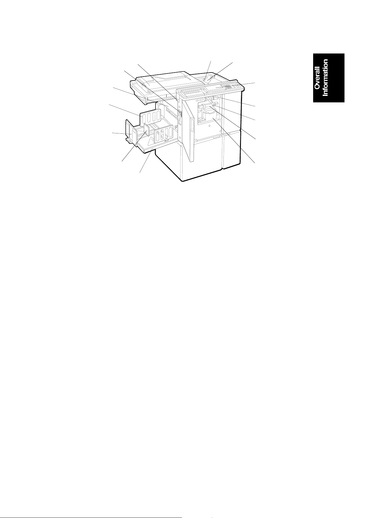
2. GUIDE TO COMPONENTS
10
1
2
3
4
5
6
7
8
9
C223V501.wmf
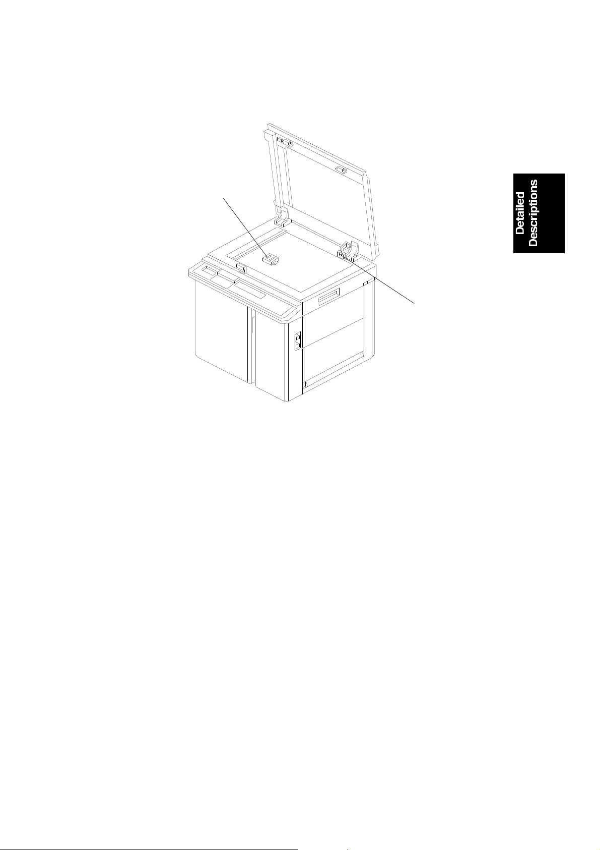
1. Platen Cover
Lower this cover over an original
before printing.
2. Original Holder
A convenient place for holding
originals while operating the
machine.
3. Original Table Release Lever
Use to open the original table unit
when installing the master.
4. Feed Roller Pressure Lever
Use to adjust the contact pressure
of the paper feed roller according
to paper thickness.
5. Separation Roller Pressure
Levers
Use to adjust the separation roller
pressure to prevent double feed.
6. Paper Feed Table
Set blank paper on this table for
printing.
7. Paper Feed Side Plates
Use to prevent paper skew.
8. Side Plate Fine Adjustment Dial
Use to shift the paper feed table
sideways
9. Paper Feed Table Down Key
Press to lower the paper feed
table.
10. Front Door
Open for access to the inside of
the machine.
1-4
Page 8
8
2
15 November 1995 GUIDE TO COMPONENTS
1
14
13
12
11
10
9
1. Master Eject Unit Open Button
Press to remove misfed paper or a
misfed master.
2. Master Cut Button
Press this button to cut the master
paper leading edge after installing a
new master roll.
3. Pressure Release Lever
Use to install the master roll.
3
4
5
6
7
C223V502.wmf
8. Ink Holder
Set the ink cartridge in this holder.
9. Paper Delivery Table
Completed prints are delivered here.
10. Small Size Paper Delivery End
Plate
Use to align the leading edges of
prints that are A4, 8
smaller.
1/2" x 11" or
4. Operation Panel
Operator controls and indicators are
located here.
5. Drum Rotation Button
Press to replace the drum.
6. Drum Unit Lock Lever
Lift to unlock and pull out the drum
unit.
7. Drum Unit
The master is wrapped around this
unit.
11. Paper Delivery End Plate
Use to align the leading edges of
prints larger than A4, 8
12. Paper Delivery Side Plates
Use to align the prints on the paper
delivery table.
13. Master Eject Container Cover
Open when removing the master
eject box.
14. Main Switch
Use to turn the power on or off.
1-5
1/2" x 11".
Page 9
5
6
13
7
MECHANICAL COMPONENT LAYOUT 15 November 1995
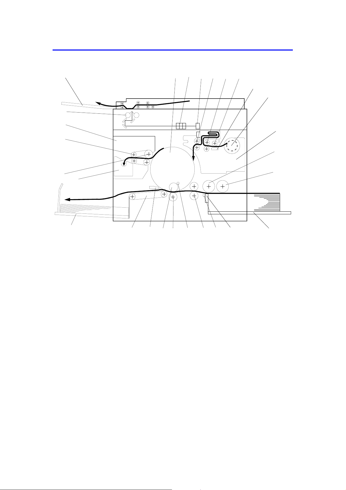
3. MECHANICAL COMPONENT LAYOUT
26
25
24
23
27
21
22
19
1234
1820
17
8
9
10
11
141516
12
1. Drum Unit
2. Lens
3. CCD
4. Reverse Roller
5. Master Feed Roller
6. Platen Roller
7. Thermal Head
8. Master Roll
9. Master Making Unit
10. Upper Separation Roller
11. Paper Feed Roller
12. Paper Table
13. Separation Plate
14. Lower Separation Roller
C223V500-1.wmf
15. 2nd Feed Roller
16. Doctor Roller
17. Press Roller
18. Ink Roller
19. Paper Exit Pawl
20. Transpo rt Unit
21. Paper Delivery Table
22. Master Eject Box
23. 1st Eject Roller
24. 2nd Eject Roller
25. Master Eject Unit
26. Exposure Lamps
27. Original Exit Tray
1-6
Page 10
201917
16
15 November 1995 DRIVE LAYOUT
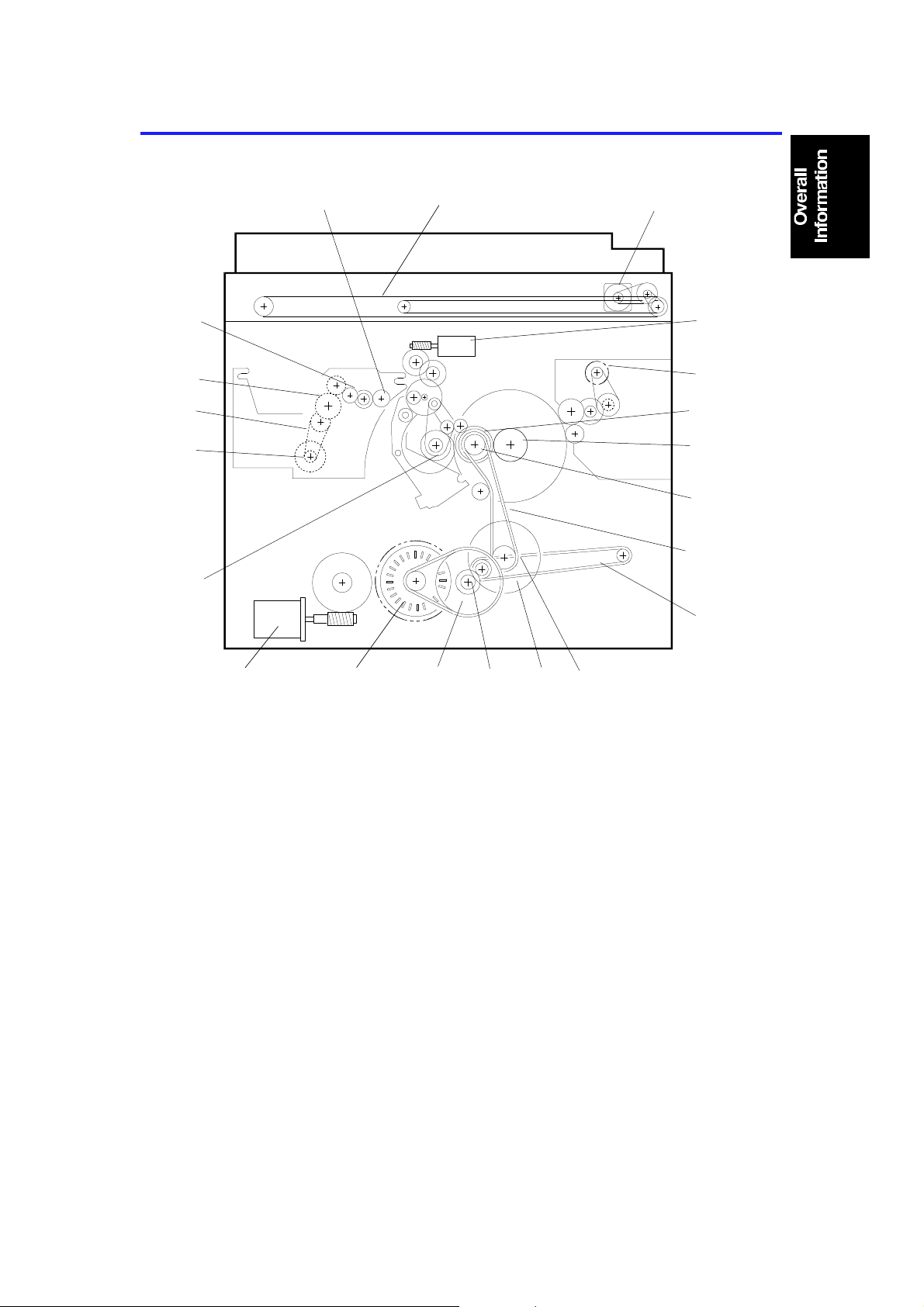
4. DRIVE LAYOUT
21
1
2
3
4
18
5
6
7
8
9
15 14
1. Scanner Belt
2. Scanner Motor
3. Image Position Motor
4. Master Eject Motor
5. Drum Drive Gear
6. Drum Unit Gear
7. Drum Drive Pulley
8. Main Drive Belt
9. Transport Belt
10. Printing Pressure Pulle y
11. Printing Pressure Gear
13
C223V504.wmf
12
11 10
12. Idle Gear
13. Idle Pulley
14. Main Motor
15. Paper Table Drive Motor
16. Paper Feed Cam Gea r
17. Master Feed Motor
18. Timing Belt
19. Platen Roller Gear
20. Master Transport Roller Gear
21. Reverse Roller Gear
1-7
Page 11

ELECTRICAL COMPONENT DESCRIPTIONS 15 November 1995
5. ELECTRICAL COMPONENT DESCRIPTIONS
INDEX
No.
Motors
15 Vacuum Fan Motor Provides suction so that paper is held firmly on the
37 Main Motor Drives paper feed, drum printing, and paper delivery
40 Paper Table Drive Motor Raises and lowers the paper feed table.
45 Image Positioning Motor Changing the relative timing of the paper feed roller
51 Master Feed Motor Feeds the master to the drum.
53 Master Buffer Fan Motor Provides suction so that the master is stored in the
54 Pressure Plate Motor Raises and lowers the pressure plate in the master
60 Air Knife Motor Drives the fan to separate the paper’s leading edge
62 Master Eject Motor Sends the used master into the master eject box.
64 Cutter Motor Drives the mechanism that cuts the master.
70 Scanner Motor Drives the 1st and 2nd scanners.
Solenoids
31 Ink Supply Solenoid Releases the spring clutch to activate the ink supply
32 Master Press Sheet Solenoid Inserts the mylar sheet between the press roller and
36 Printing Pressure Solenoid Engages the pressure on/off lever when a paper
39 Paper Feed Solenoid Releases the sector gears to feed the paper.
41 Detection Pin Release
Solenoid
46 Master Feed Clamper
Solenoid
47 Drum Lock Solenoid Prevents the drum unit from being removed during a
48
Master Eject Clamper Solenoid Open the master clamper to eject the master.
59 Master Eject Solenoid Presses the lower master eject roller against the
NAME FUNCTION
transport belt.
unit components.
and the drum to adjust the vertical image position.
master box during the master eject operation.
eject mechanism.
from the drum.
pump.
the drum during a quality start operation.
misfeed occurs.
Releases the detection pin arm to apply printing
pressure during a quality start operation.
Open the master clamper to catch the master during
master feed.
printing run.
drum surface.
Switches
1 Scanner Unit Safety Switch Cuts off the power line of the main and paper table
drive motors when the scanner unit is open.
2 Paper Table Down Button Instructs the CPU to turn on the paper table drive
motor to lower the paper table.
5 Paper Table Open Switch Checks whether the paper table is opened or not.
1-8
Page 12

15 November 1995 ELECTRICAL COMPONENT DESCRIPTIONS
INDEX
No.
7 Paper Table Safety Switch Stops lowering the paper feed table to prevent users
12 Front Door Safety Switch Informs the CPU when the front door is open, and
18 Test Switch Disables the front door, paper table, master eject
20 Delivery Table Open Switch Checks whether the delivery table is open or not.
21 Main Switch Turns the power on or off.
22 Air Knife Motor Safety Switch Cuts off the power line of the air knife motor when
27 Drum Rotation Button Instructs the CPU to rotate the drum at 10 rpm.
28 Drum Unit Safety Switch Checks whether the drum unit is set correctly or not.
30 Master Eject Unit Safety
Switch
44 Master Cut Button Instructs the CPU to feed a short strip of master
52 Left Cutter Switch Detects when the cutter position is at the far left
61 Master Eject Box Switch Checks whether the master eject box is set properly.
66 Right Cutter Switch Detects when the cutter position is at the far right
76 ADF Set Switch Detects if the optional document feeder is closed.
NAME FUNCTION
from catching their fingers under it, by cutting the ac
power. It also closes when the paper feed table is
closed.
cuts off the power line to the paper table drive motor.
unit, and scanner unit safety switches.
the master eject unit is open.
Cuts off the power line when the master eject unit is
open.
paper and cut the master paper.
(operation side).
(non-operation side).
Sensors
3 Paper End Sensor Informs the CPU if there is paper on the paper table.
4 Paper Width Sensors Informs the CPU of the printer paper width.
6 Paper Length Sensor Informs the CPU of the printer paper length.
8 Paper Table Height Sensor Informs the CPU if the paper table is at the paper
feed position.
11 Paper Table Lower Limit
Sensor
13 Printing Pressure Sensor Informs the CPU if printing pressure is applied. Also,
14 1st Paper Exit Sensor Detects paper misfeeds.
17 2nd Paper Exit Sensor Detects paper misfeeds.
33 2nd Drum Position Sensor Checks the position of the drum.
35 1st Drum Position Sensor Checks the position of the drum.
38 Drum Rotation Sensor Supplies timing pulses to the CPU based on the
49 Drum Master Sensor Informs the CPU if there is a master on the drum.
50 Master Buckle Sensor Informs the CPU if the master is buckling.
55 Lower Pressure Plate Sensor Informs the CPU if the pressure plate in the master
56 Upper Pressure Plate Sensor Informs the CPU if the pressure plate in the master
Informs the CPU if the paper table is at the lowest
position.
detects paper misfeeds.
main motor speed.
eject mechanism is at the lower limit position.
eject mechanism is at the upper limit position.
1-9
Page 13

ELECTRICAL COMPONENT DESCRIPTIONS 15 November 1995
INDEX
NAME FUNCTION
No.
57 Full Master Box Sensor Informs the CPU whether the master eject box is full
of masters or not.
58 Master Eject Sensor Detects used master misfeeds.
65 Master End Sensor Informs the CPU when the master roll in the master
making unit runs out.
68
Scanner Home Position Sensor Informs the CPU when the 1st scanner is at home
position.
72 Platen Cover Position Sensor Detects when the platen cover or the optional
document feeder is opened more than 25 degrees
above the exposure glass.
75 Original Sensor Detects if an original is placed on the exposure glass.
Printed Circuit Boards
9 Image Processing PCB Control the image processing performance.
29 Main Control PCB Controls all machine functions both directly and
through other boards.
42 AC Drive PCB Controls the ac components using relays.
43 Ink Detection PCB Informs whether ink is present in the drum.
71 CCD PCB Converts light intensity into an electrical signal.
74 A/D Conversion PCB Converts analog signals into digital signals.
Counters
23 Master Counter Keeps track of the total number of masters made.
24 Total Counter Keeps track of the total number of prints made.
Others
10 Transformer Steps down the wall voltage.
16 Power Supply Unit Provides power for all dc components.
19 Circuit Breaker Cuts the ac line off.
25 Operation Panel Interfaces the CPU and the operator.
26 Drum Rotation LED Turns to green from red when the drum stops at the
home position.
34 Noise Filter Filters out electrical noise from the ac power input
line.
63 Reverse Roller Clutch Transfers drive to the reverse roller.
67 Thermal Head Creates the master using heat.
69 Xenon Lamp Illuminates the original.
73 Xenon Lamp Stabilizer Stabilizes the power supplied to the xenon lamp.
1-10
Page 14
Master
Making/
Master
Feed
15 November 1995 PRINTING PROCESS
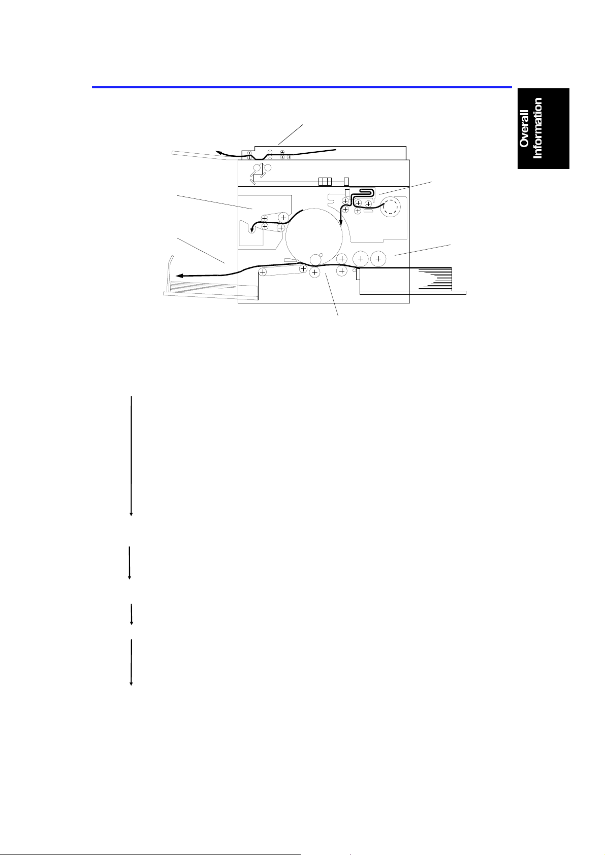
6. PRINTING PROCESS
Master
Ejection
Paper
Delivery
1. Master Ejection/
Scanning/
Master Making:
At the start of the print ing run, the machine
ejects the used master wrapped around the
drum into the master eject box.
Scanning
Printing
Shown with
optional ADF
attached
Paper
Feed
C223V500.wmf
At the same time, the machine scans the
original on the exposure glass (reflected light
goes to the CCD via the mirrors and the lens.
The scanned image is tran sfe rred to the master
using a thermal head.
While the old master is still being ejected, the
new master is stored in a box.
2. Master Feed: After the old master has been ejected, the new
master is fed to the drum and wrapped around
it. At the same time, the master is cut of f fro m
the roll.
3. Paper Feed: I nd ividu al she et s of pa per are fe d to the drum.
4. Printing: The paper fed from the paper fee d mechan ism
is pressed onto the drum. This tra nsf ers ink to
the printer paper through the drum screen and
the master.
5. Paper Delivery: The exit pawl and air knife peel off the printo ut ,
and the printout is ejected onto the paper
delivery table.
1-11
Page 15

MAJOR DIFFERENCES BETWEEN THE C218 AND THE C223 MODELS 15 November 1995
7. MAJOR DIFFERENCES BETWEEN THE C218
AND THE C223 MODELS
The C223 model was develo pe d ba sed on the C218 model.
The following table list s the major dif fe rences between the C223 and the
C218 models.
No. Item Remarks
1 Exposure Lamp The exposure lamp has been changed from a fluorescent
lamp to two xenon lamps.
2 Master Buffer
Mechanism
3 Quality Start A quality start mechanism has been added to minimize waste
4 Platen Roller Holding
Method
5 Leading Edge Margin The leading edge margin has been reduced from 8 mm to 5
6 Separation Roller
Shaft
7 Noise Reduction
Cover
8 Paper Size Sensors The paper size detection board has been eliminated. The
9 Optional Equipment The following items have been newly lined up as the options
The master process time has been reduced as a result of the
new master buffer mechanism. The master making process
starts at the same time as the master eject operation starts.
prints after a long idle interval.
To ensure correct platen roller positioning, the platen roller is
held by two screws instead of two levers.
mm. The drum screens and printing pressure cam have been
changed.
The diameter of the separation roller shaft has been
increased. Due to this modification, the paper feed vibration
noise has been reduced.
The noise reduction cover has been added to reduce paper
feed noise.
paper size sensors directly send signals to the main control
board.
for the C223 model:
Sorter Stapler DS20A/DS20B
DF II (50 sheets)
Large Capacity Tray LT4000
10 Line/Photo Mode To allow clear prints of originals having line and photo areas,
Line/Photo mode has been added. Photo mode is processed
using Error Diffusion, which is similar to the CAPIX method
used in the C210 and C218 models.
11 Economy Mode If "Economy" mode is selected on the operation panel, a
lower thermal head energy is applied when a master is
made. As a result, the image will be lighter than normal and
ink consumption will be less.
12 CS Mode Customers can register three of seven frequently used user
SP modes in CS mode. The setting can be recalled using the
CS mode key which is newly added.
13 Scanner Lock Lever To facilitate operation, the shape of the scanner lock lever
has been changed.
14 Paper Return
Mechanism
The paper return mechanism (a solenoid and a dc motor)
has been eliminated.
1-12
Page 16

15 November 1995MAJOR DIFFERENCES BETWEEN THE C218 AND THE C223 MODELS
No. Item Remarks
15 Cassette Size
Detection
16 Paper Feed Motor The paper feed motor has been changed from an ac motor to
17 Original Tray Cover To prevent the originals from dropping when the ADF is
18 Base Pads The shape of the base pads has been changed so that they
The cassette size detection board (red switch) has been
eliminated. (The cassette has been changed from standard
equipment to an option).
a dc motor.
opened, a cover has been added on the original tray.
can be used for both the normal table and the table for the
LCT.
1-13
Page 17

SECTION 2
DETAILED SECTION
DESCRIPTIONS
Page 18
15 November 1995 MASTER EJECT
1.
MASTER EJECT
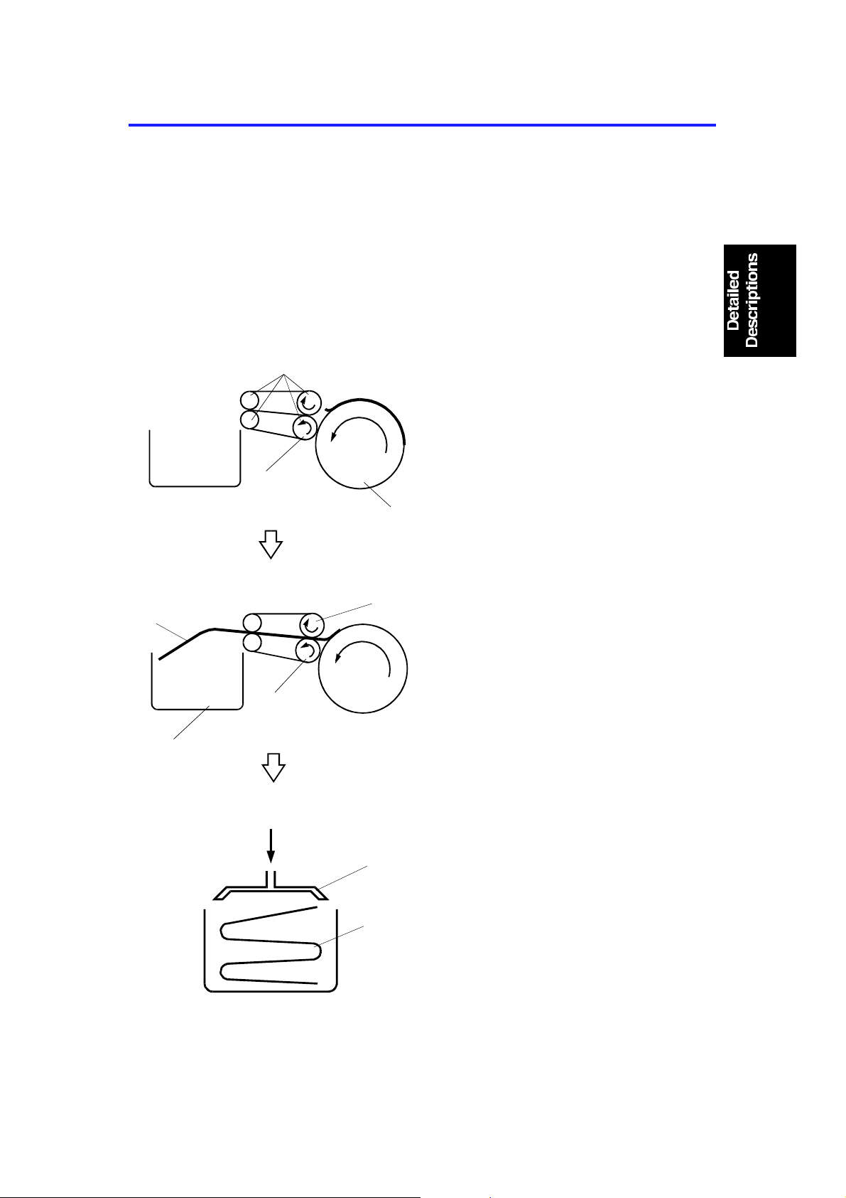
1.1 OVERALL
At the end of the printing cycle, the use d master remains wrapped around the
drum to prevent the ink on th e drum surface from drying. Whe n th e Master
Making key is pressed to make a new master, the used master is ejected
from the drum.
The master is pulled off the drum, th en it goes thro ug h the eje ct rollers and
into the master eject box. A pressure plate then compacts the used master.
[D]
[G]
[C]
[A]
[F]
[B]
C223D505.wmf
[E]
Drum
•
The drum [B] rotates in reverse
(opposite to the printing direction).
•
The master eject rollers [A] rotate.
•
The lower eject roller [C] is
pressed against the drum.
•
The trailing edge of the master,
which curls up from the drum,
passes between the upper [E] and
lower [F] eject rollers, and the
master [D] is peeled off th e dru m
and dumped into the mast er eje ct
box [G].
C223D506.wmf
C223D507.wmf
[H]
[I]
•
The pressure plate [H] compa cts
the ejected master [I].
2-1
Page 19
MASTER EJECT 15 November 1995
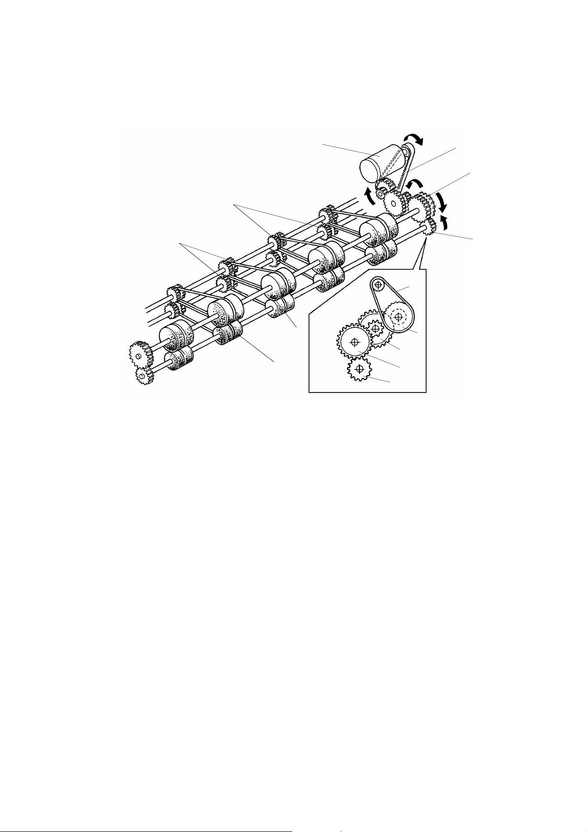
1.2 MAS TER E JE CT ROLLE R ROTATI O N MECHANIS M
[A]
[B]
[E]
[J]
[I]
[F]
[B]
[G]
[C]
[D]
[H]
[E]
[F]
C223D511.img
When an original is in place and the Mast er Making key is pressed, the main
motor starts turning at 22 rpm in re verse . As a resu lt, the drum also turns in
reverse (compared with the rotation direct ion for prin ting).
At this time, if the drum master sensor detects a master on the drum, the
master eject motor [A] starts rotating. Drive is transmitted to gear [E] and to
the upper first eject rollers [G] through the timing belt [B] and gears [C] and
[D]. Gear [F] drives the lower first eject rollers [H] . The belts [I] transmit drive
from the first eject rollers to the upper and lower second eject rollers [J].
(If the drum master sensor d etects no master on the drum when the Master
Making key is pressed, the mach ine skips t he master eject process and goes
directly to the master making process.)
After the master eject process is co mple te d, the drum ret urns to its home
position. The master eject rollers then stop rotating.
This model has four rollers on each eject roller shaft.
2-2
Page 20
[D]
15 November 1995 MASTER EJECT
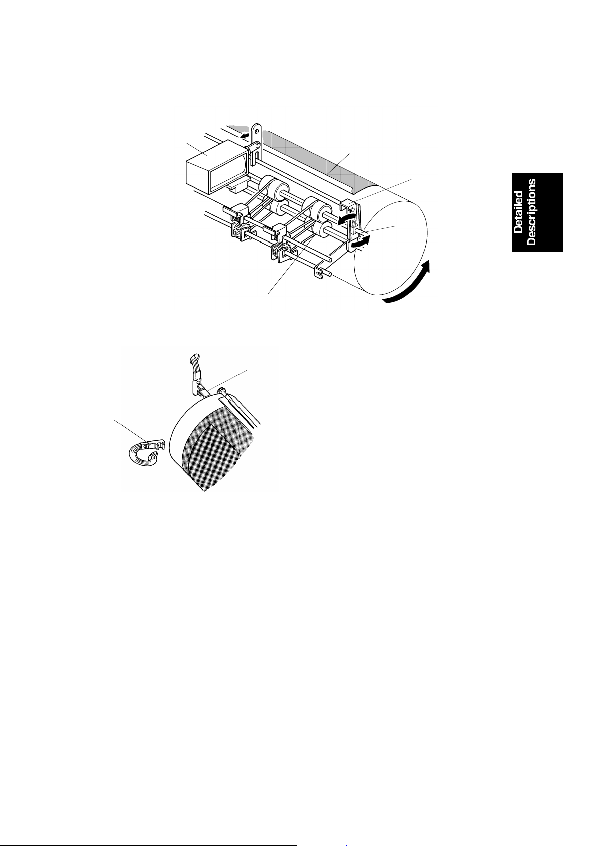
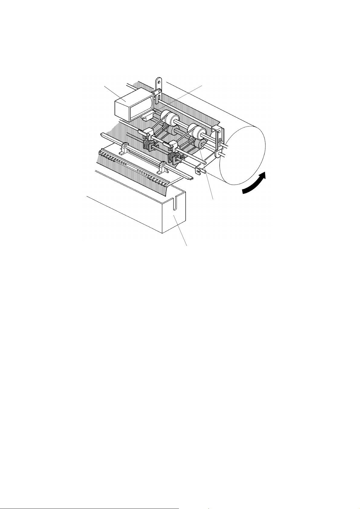
1.3 MASTER EJECT ROLLER DRIVE MECHANISM
[H]
[G]
[A]
[B]
[C]
[E]
C223D508.img
[F]
C223D510-1.img
The drum position is detected by th e first [G] and secon d [H] drum position
sensors. When the drum reach es its ho me position, the first drum position
sensor [G] is actuated by the int erru pt er [F] on the rea r sid e of the drum.
To eject the master, the drum turns in reverse (opposite to the printing
direction). When the drum is 70° past the 1st dru m p osit ion sensor, the
master eject solenoid [A] turns on and the suppo rte r [C] rotates
counterclockwise on the upper eject roller shaft [D]. This forces the lower first
eject roller [E] against the dru m.
As the drum turns, the curled trailing edge of the master [B] passes be twe en
the upper and lower first eject rollers. The first eje ct rolle rs the n peel the
master from the drum.
2-3
Page 21
[C]
MASTER EJECT 15 November 1995
[A]
[D]
[B]
C223D509.img
When the drum is 109 degree past the 1st drum position sensor, the master
eject solenoid [A] turn s off , sep ara ting the lower first eject rollers [C] from the
drum.
Shortly after the lead ing edge of the ejected master h as passed between the
upper and lower first eject rollers, the master eje ct sen sor [B ] is a ctiva ted.
The master is then dumped int o the master eject box [D].
2-4
Page 22
15 November 1995 MASTER EJECT
Print key on
First Drum Position Sensor
Master Eject Solenoid
Sensor ON Check
70°
Drum Rotation
Reverse Reverse
Master Eject Sensor
Master Eject Motor
Misfeed Indicator Lights
39° 18°
50° 50°
68°
Forward
C223D512.wmf
[Master Eject Misfeed Detection]
The misfeed indicator for the master eject section blinks in the fo llowing
cases:
Case 1: The master eject sensor is not activa te d an d the drum has turned
50 degrees more (still in reverse and after de-activat ion of the
master eject solenoid ). The machin e knows that the eject rollers
have failed to catch the maste r. So the drum ret urn s 68 de gre es (in
the printing direction) to rep ea t the mast er eject process once
again. The master eject sole noid is a gain en erg ized while the drum
turns another 18 degrees to try to catch the master.
If the master eject sen sor on ce again fails to detect the maste r,
then the drum returns to its home position and the misf eed
indicator blinks.
Case 2: The drum finishes its rotation for the master ejecting pro cess an d
returns to the home posit ion, but the master eject sen sor do es no t
turn off. This means that the master is still in between the master
eject rollers, the misfeed indicator blin ks.
2-5
Page 23
[G]
MASTER EJECT 15 November 1995
1.4 MAS TER E JE CT CLAMPE R MECHANI S M
[F]
[B]
[A]
[E]
[C]
[D]
C223D513.img
When the drum has rotated 306° (in reverse) past the 1st drum position
sensor, the master eje ct clamper solenoid [A] turns on and le ver [B ] moves
counterclockwise a short way as shown . This move s the cam [D] inside the
drum. Drum rotation brin gs th e clamp er sector gear [E] against the cam [D] .
Gear [F] turns counterclockwise as it en ga ges the clamper sector gear, thus
opening the master clamp er [G ]. This re lea ses th e master from the drum.
The drum keeps on turning until the interrupter at the rear of the drum has
gone 13 degrees past the first drum posit ion sensor. Then, the main motor
turns off. Half a second later, the master eject clamper solenoid [A] turns off
and spring [C] pulls cam [D] back to its initia l posit ion . The drum then rotates
forward to its home position .
2-6
Page 24
[M]
[A]
[K]
[C]
[D]
[E]
[F]
[G]
15 November 1995 MASTER EJECT
1.5 P RESSURE PLATE UP/DOWN MECHANISM
[B]
[L]
[I]
[H]
[J]
Pressure Plate Down
C223D514.img
When the interrupter at the rear of the drum interrupts the first drum position
sensor (this happens at th e en d of the master eject process), th e pre ssure
plate motor [B] starts. This drives gear [H] clockwise by mea ns of gears [C],
[D], [E], and [F].
Pin [I] on gear [H] moves link [G] down until the link interrupter [L] interrupts
the lower pressure plate sensor [J] . Sp ring [M] pulls down on the pressure
plate and the ejecte d master in the master eject box is compresse d by the
pressure plate [A].
If the master box full sensor [K] does not turn on when the pressu re plate
goes down, it means the master eje ct box is fille d with eject ed ma ste rs. In
this case, the master eject bo x full ind icator blinks, and the machine stop s
after a new master is wrapped around the drum.
The indicator goes out after the master eject box switch has been turned off
and on. Then the maste r box full sensor is checked again afte r one ma ste r
has been fed. This is to prevent the indicator from being reset without
removing the ejected masters from the box. When the indicator is blinking,
the Master Making key does not work, but the Print Start key and Proof key
work so that the master curre nt ly o n th e dru m ca n be used for prin ting.
2-7
Page 25
[B]
[D]
MASTER EJECT 15 November 1995
[A]
[G]
[C]
[F]
[E]
C223D515.img
Pressure Plate Up
When the master has been wrapped around the drum in the master makin g
process and the master cutter leaves the home position to cut the master, the
pressure plate moto r [B] starts rotating to ra ise th e pressure plate.
When the pressure plate moto r [ B] turn s, th e ge ar [C] is driven through the
relay gears. The pin [F] on the gear inserted into the link [D] rises and lift s the
left end of the link, thus raising the pressure plate.
The gear [C] continues turnin g until th e int erru pt er [G ] at the fron t en d of the
pressure plate blocks the upper pressu re pla te sensor [A]. At this time, the
master eject motor [B] stop s and the pressu re pla te is held in th e up pe r
position.
Pressure Plate Motor Lock Detection
To prevent the pressure pla te motor from locking, "E-12" lig ht s up on the
operation display panel under the following conditions:
1. When the lower pressure plate sen sor [E ] is not activa te d with in 8
seconds after the pre ssure plat e motor starts to lower the pressure plate.
2. When the upper pressure plat e sensor [A] is not activated with in 4
seconds after the pre ssure plat e motor starts to raise the pressure plate.
2-8
Page 26
30 rpm
500 ms
70°
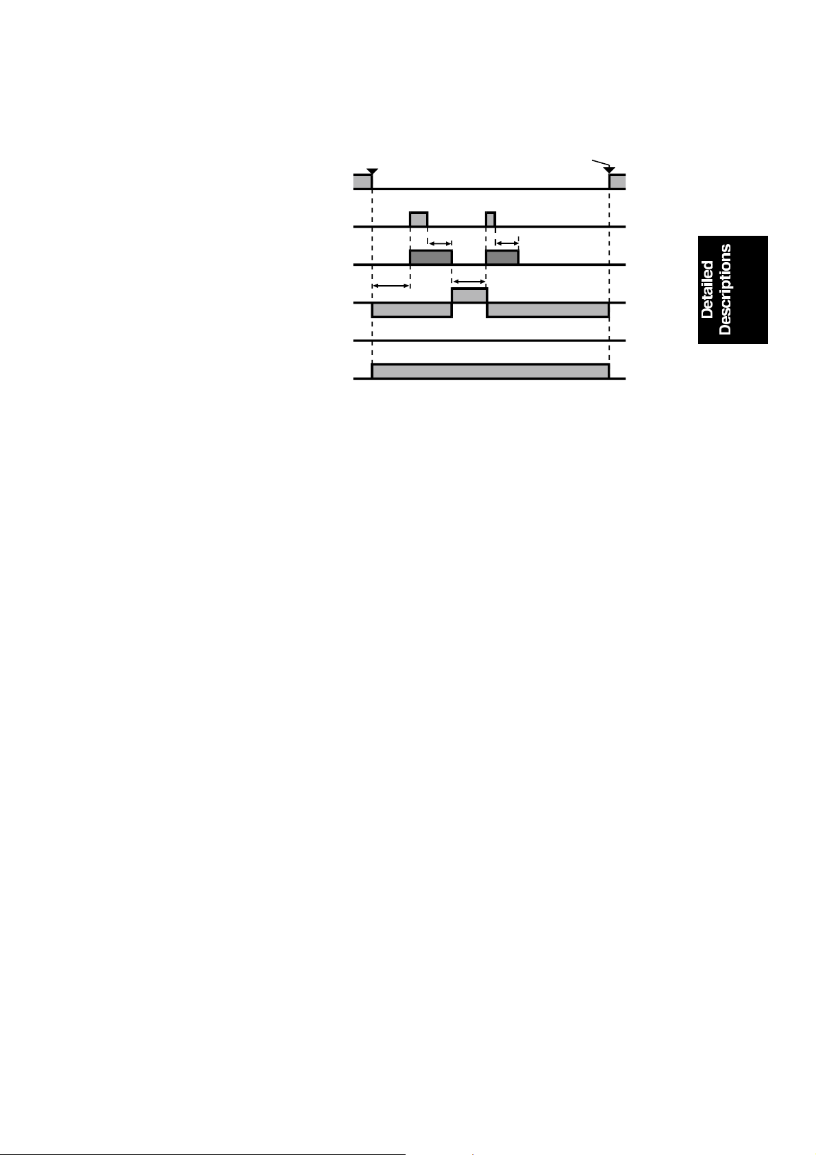
15 November 1995 MASTER EJECT
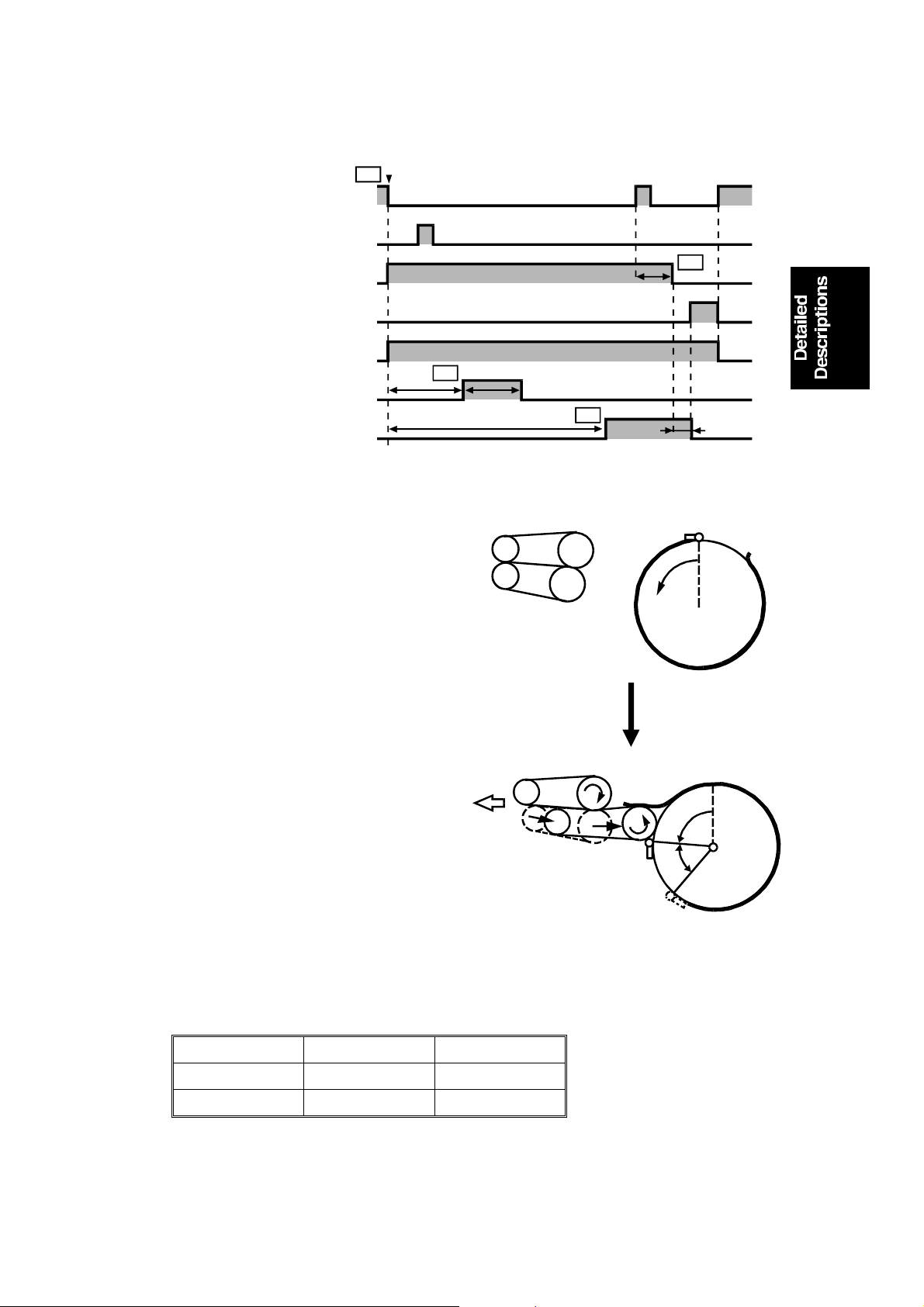
1.6 E LECTRI CAL TI MI NG
T1
First Drum Position Sensor
Second Drum Position Sensor
Main Motor Reversing
Main Motor Forwarding
Master Eject Motor
Master Eject Solenoid
Master Eject Clamper Solenoid
22 rpm
X1
T2
T1: When the Master Makin g key is
pressed, the main moto r a nd
master eject motor start tu rnin g. At
the same time, the paper table drive
motor starts turning to lift the paper
table to the paper feed position.
T2: When the drum ro ta tes X1 degrees
past the first drum position sensor
actuation position (drum home
position), the master eject solenoid
is energized. This presses the lower
eject rollers against the drum
surface. The master eject solenoid
is de-energized when th e dru m
rotates X2 degrees more.
The drum rotation angles X1 and
X2 depend on the drum type. This
machine has two types of dru ms:
one is the A3/DLT drum (standard),
and the other is the A4/LT drum
(optional). X1 and X2 for each drum
are as follows
306°
X2
T4
13°
T3
C223D516.wmf
0°
C223D612.wmf
0°
39°
C223D613.wmf
Drum Type A3/DLT A4/LT
X1 (degree) 70 174
X2 (degree) 36 55
2-9
Page 27
MASTER EJECT 15 November 1995
T3: When the drum rotates 306
degrees pas t the home posit i o n, the
master eject clamper solenoid is
energized.
T4: When the drum ro ta tes 13 degrees
past the drum home posit ion , the
drum stops rotating.
500 milliseconds later (the drum
completely stops during this period),
the master eject clamper soleno id is
de-energized and the drum starts
rotating forward. The drum then
returns to its home position. The
master eject process is now over.
Soon after this, the mach ine starts
feeding a new master and the drum
starts rotating in reverse to begin
the master making process.
0°
C223D614.wmf
0°
13°
C223D615.wmf
306°
2-10
Page 28
15 November 1995 SCANNER
2.
SCANNER
2.1 OVERALL
A book type scanner is used for the #C223 model. There are two modes for
scanning originals.
Platen Cover Mode: The original is placed on the exposure glass, and the
scanner motor drives the scanner to scan the original.
ADF Mode: When an optional Documen t Fee de r is inst alle d, the origin al is
fed onto the exposure gla ss. The scann er move s 22 mm away from the CCD
and remains still as it scans the original. The scanner comes back to the
home position when the scanning is finished.
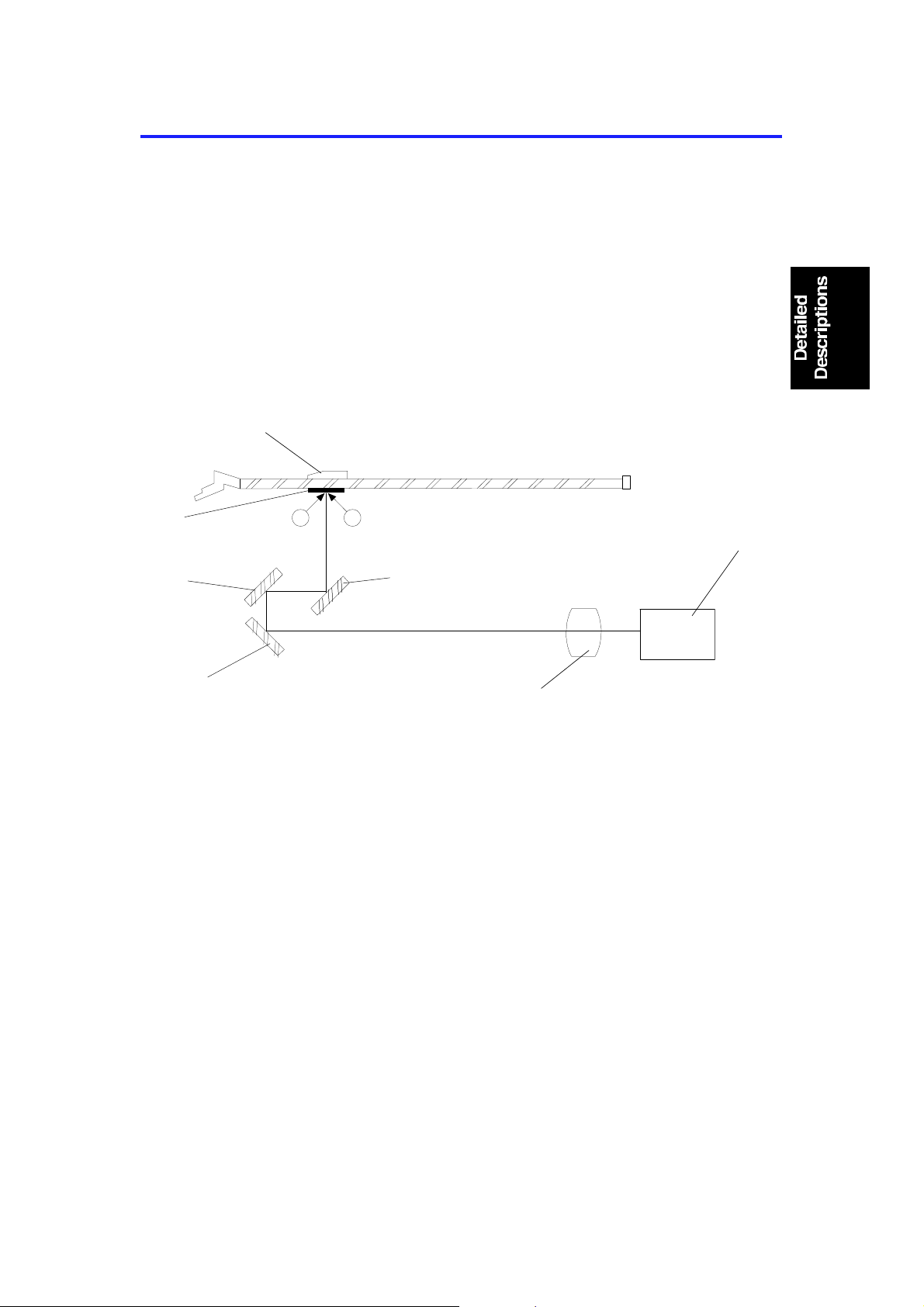
[G]
[F]
[E]
The light from the xenon lamps [A] is reflected from the orig ina l by the first
[B], second [F], and third [E] mirrors t hro ug h th e len s [ D] to the CCD [C] .
[I]
[A]
[A]
[B]
[D]
[C]
C223D517.wmf
In the Platen Cover Mode , the CCD reads the white plate [G ] on the back of
the original scale [I] each time be fo re scanning to obtain a standa rd white
level. The standard white dat a are used to correct distortion. The scanner is
at its home position when it rea ds th e white level.
In the ADF mode, as the scanner move s 22 mm, th e CCD read s the wh ite
plate installed on the ADF.
2-11
Page 29
SCANNER 15 November 1995
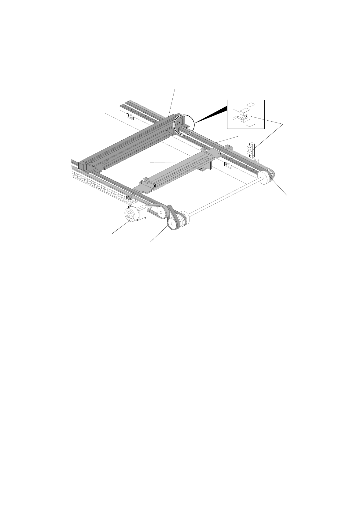
2.2 S CANNER ME CHANI SM
[B]
Front Side
[E]
[D]
[C]
[F]
Rear Side
[A]
[G]
C223D518.wmf
The scanner motor [A] (a stepper motor) drives the scanners. The first
scanner [B], which consists of the expo sure lamp an d th e first mirror, is
driven by the first scanner belt [F]. The seco nd scann er [C] , which consists of
the second and third mirrors, is drive n by th e second scanner belt [D]. Both
scanners move along the gu ide rails.
The timing belt [G] moves t he secon d scanner at half the speed of th e first
scanner. This is to maintain the focal distance between the original and the
lens during scanning.
The scanner home position is detected by the scanne r home position sensor
[E]. In the Platen Cover Mod e, the sca nner scans the original on the
exposure glass for the full A3 /DLT length, then retu rns un til th e scanner
home position sensor is activat ed . In the ADF Mode , th e scan ne r moves 22
mm backwards (away from the CCD), to scan the origin al which is fe d by th e
ADF. When the master making process is finished and the ADF motor st ops,
the scann e r goes back to the home positi on.
2-12
Page 30
15 November 1995 SCANNER
2.3 P LATEN CO VER POSITION DETECTION
[B]
[A]
C223D519.wmf
When the platen cover is opene d ab ou t 25 deg rees, the Platen Cover
Position Sensor [A] is deactiva ted. When this sensor is deactivate d, the
Original Sensor [B] is able to det ect the origin al on the expo sure glass.
When the Platen Cover Position Sensor is deactivat ed and the Origin al
Sensor detects no original on the expo sure glass, the machin e indicates
"SET THE ORIGINALS" on the operat ion displa y. This is t o pre ven t wast ing
of the master that wo uld occur whe n the Master Making key is pressed with
no original placed on the exposure glass.
When the original is placed on the expo sure glass and the Master Making
key is pressed with the pla te n cover opened more than 25 degrees (a s the
Platen Cover Position Senso r is deact ivat ed ), th e shadow erase function is
enabled.
2-13
Page 31

SCANNER 15 November 1995
Notes regarding the shadow erase function
•
Margins of 1 mm [0.02"] on all four side s of th e orig ina l will be erase d. Th e
width of the margins will change depending on the rep rod uction ratios.
•
Shadows near the edge of a book might not be erased completely.
•
If the shape of the orig inal is as shown below, shadows might appe ar on
the prints. In this case, make the master with the platen cover closed.
Shadow
Scanning directio n
C223D520.img
•
If there is a line or solid image on the margin at the center or at the edges
being erased, parts of the image might be erased as shown be low.
Scanning directio n
C223D521.img
2-14
Page 32

15 November 1995 SCANNER
2.4 E LECTRI CAL TI MI NG
2.4.1 Platen Mode
2-15
C223D522.wmf
Page 33

SCANNER 15 November 1995
Master Feed Lengths
a: 18.7 mm
b: 0.7 mm
c: 10.7 mm
d: 13.7 mm
e: 420 mm
f: 62.5 mm (211 mm: A4/LT drum)
g: 40 mm (61 mm: A4/LT drum)
The timing chart shows how scan ning takes place at the same time as
master ejection and master making.
T1: When the master making key is p resse d, the main motor starts reverse
rotation at 22 rpm. At the same time , the mast er fe ed moto r and the
reverse roller clutch turn on to feed th e mast er 18 .7 mm. Then they
switch off, and the scanne r motor turns on shortly afterwards.
T2: When the scanner h as move d 20 mm fro m the home position, the master
feed motor, master buckle fan motor, and the reverse roller clut ch tu rn on.
T3: The thermal head starts to make the new mast er whe n the master has
been transported 1mm.
T4: When 420 mm (the maximum scan length) has been scanned the
scanner motor starts re versin g to return the scanner to th e ho me po sitio n.
T5: After the scann er home po sition sensor has been actuated, the scanner
motor rotates forward the n reve rses to stop the sca nner at the correct
home position.
2-16
Page 34

15 November 1995 SCANNER
2.4.2 ADF Mode
C223D611.wmf
The above timing chart shows scan ne r timing when an optio na l ADF has
been installed.
T1: When originals are inse rte d in th e ADF un it, the origin al set sensor is
activated.
T2: When the Master Makin g key is pressed, the ADF motor rotates the
pickup roller and the feed roller to feed the bot to m origin al into the ADF.
T3: The ADF motor stops rotating clockwise when the origin al has bee n fed
14.5 millimeters after the original registration sensor was activated. After
50 milliseconds, the ADF motor starts rotating counterclockwise to rotate
the 1st original transport roller.
T4: The ADF motor stops again when th e orig ina l has be en fed 22 millimeters
after the scan line sensor was activated.
Scan Line Sensor On
Original
ADF Scanning Position
C223D610.wmf
T5: When the ADF motor stops, the scanner motor starts reversing to bring
the scanner to the ADF scan nin g po sitio n.
2-17
Page 35

MASTER FEED 15 November 1995
3.
MASTER FEED
3.1 OVERALL
[A]
[D]
[B]
[C]
C223D500-1.wmf
The thermal head [B] burns the imag e (scan ned by th e CCD) onto th e mast er
[A] as it is being fed to the dru m [ C]. The used master is ejected at the same
time that the new master is printed, and the new master is stored in the
master box [D] until the old master ha s bee n comp let ely eje cted. The master
is then clamped to and wrapped around the drum.
The master box mechanism reduce s the amount of time neede d to make a
new master, because the new mast er can be mad e at the same time tha t the
old one is fed out.
2-18
Page 36

15 November 1995 MASTER FEED
3.2 MASTER FEED CLAMPER OPENING MECHANISM
[A]
[B]
[C]
C223D510-2.img
[G]
[F]
[H]
[D]
[E]
C223D526.img
After the master eject pro cess is f inish ed and the in te rrup ter [A] is positioned
in the first drum position senso r [B] , th e main moto r turns on and the drum
starts rotating (22 rpm) in reverse (opposite to the printing direction).
When the drum has turned 160 degrees past the actuation position of the
second drum position senso r [C], the master feed clamper solenoid [D] turn s
on, and the cam [H] moves inside the drum.
When the drum has turned ano th er 58 .5 deg ree s, the sector gear [F] rotate s
upwards as it contacts the cam [H] . This en ga ges the secto r gea r wit h gear
[E], which turns counterclockwise to open the clamper [G]. At the same time,
the drum stops and the clamper remains open to cat ch and clamp the
master’s leading edge.
2-19
Page 37

[A]
MASTER FEED 15 November 1995
3.3 MASTER FEED MECHANISM
[D]
[B]
[C]
[E]
C223D500-2.wmf
C223D501.wmf
To minimize the first print time, the maste r ma king proce ss starts just after
the master making key is pressed.
When the master making key is pressed , th e drum starts rotating in reverse
to eject the master that is wrapped aro und th e dru m. At the same time , th e
master feed motor [A] sta rts tu rning and the reverse roller clutch [B] is
energized.
When the master has been transported 18.7 mm, the master feed roller and
the reverse roller clutch stop. They start again just after original scan ning
starts.
When the master has been tran sported a further 10.7 mm (when the leading
edge is 6 mm past the reverse roller [C]), the reverse roller clutch is turned off
but the master feed motor con tin ue s to rot at e. As a result, the master leading
edge stays at 6 mm past the reverse roller, and the ma ste r buckles up behind
2-20
Page 38

15 November 1995 MASTER FEED
the reverse roller. Until the drum comes to the maste r fee d positio n, the new
master fed by the master feed motor during the eject process is stored in the
master box [D]. The suction provided by the master buffer fan motor [E] helps
to bring the master into the box.
The main results of this mechanism are:
•
A much greater length of new mast er can be mad e befo re it sta rts to be
wrapped around the drum.
•
The new master can start to be mad e much earlier during the machine ’s
operation cycle, saving time.
The master buffer fan mot or tu rns on when maste r ma king starts, and it stays
on until the reverse roller starts feeding the master again to be caught by the
master clamp on the drum.
2-21
Page 39

MASTER FEED 15 November 1995
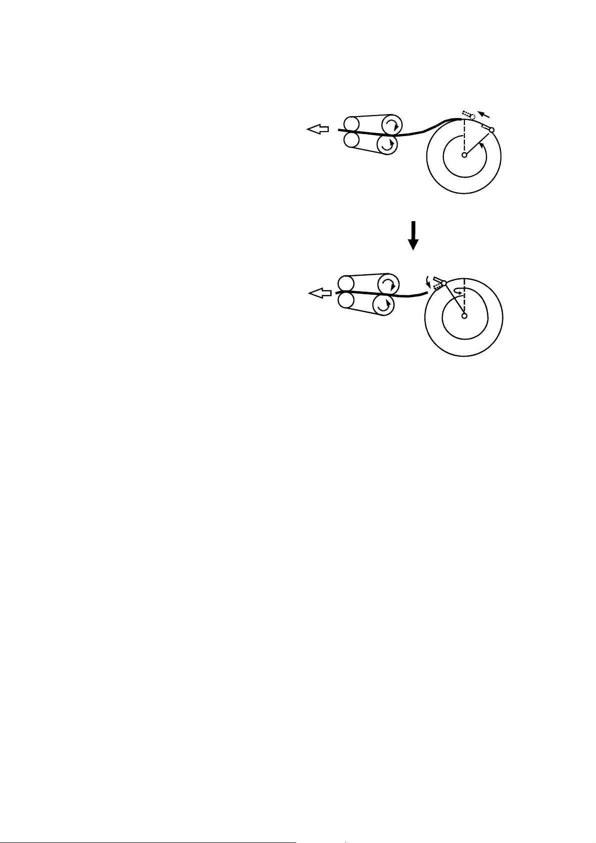
3.4 MASTER WRAPPING MECHANISM
[B]
[A]
[B]
[E]
[C]
[D]
C223D502.wmf
[C]
[D]
C223D503.wmf
When the drum stops at the master feed position (at this time , th e mast er
clamper is open), the reverse rolle r clutch [A] turns on again. When the
master has been transported 18.7 mm and the master leading edge has
reached the master clampe r, th e reve rse roller clutch and the master feed
clamper solenoids turn off . The maste r le ad ing edge is clamped by the
master clamper.
After the master clamper catches the master leading edge, the drum rot at es
at 22 rpm while the master buckle sensor [B] is on. The master feed motor
continues to feed the master at this sta ge . The drum pulls t he master faster
than the master feed motor feeds it, so the maste r b uckle senso r will
deactivate eventually. When this happen s, the main moto r stops unt il the
sensor is activated by the maste r buckle again. In this way, the master is
wrapped around the drum keeping a buckle between the reverse roller [C]
and the master feed roller [D]. This buckle prevents the master that is still
2-22
Page 40

15 November 1995 MASTER FEED
under the thermal hea d fro m b ein g pu lled; if a long master is being made, this
will adversely affect copy quality.
When the new master is finished, th e mast er fe ed spee d incre ase s (t o 4
times the master making speed) and the maste r cutter cuts the master when
the appropriate length of ma ste r has be en tran spo rte d.
Even if a master eject jam occurs, the master making operation continues.
When a master eject jam is detected, the machine stops after master making
and cutting is done (during th is perio d, the new master is stored in the master
box [E]). When the reset key is pre ssed aft er th e jammed master is removed,
the reverse roller clutch turns on to tra nsp ort the maste r t o the mast er
clamper, and the master clamp er clamp s t he lead ing edg e. Th e dru m rotates
at 22 rpm to wrap the master.
2-23
Page 41

MASTER FEED 15 November 1995
3.5 CUTTER MECHANISM
[A]
[E]
[C]
[D]
[A]
[B]
[B]
C223D527.img
[F]
[G]
C223D528.img
After the master makin g pro cess is f inish ed , the master feed motor turn s off
and the cutter motor [A] sta rts tu rnin g.
The cutter motor [A] starts turning in reverse (see the arrows) when the cutter
holder [B] pushes the left cutt er switch at th e front (ope rat ion side) end of the
cutter rail; this is the cutter holder home position. This drives the cutt er ho lde r
[B] toward the rea r (non -op eration side) by means of the ge ar/pulley [C] and
the wire [D] on which the cutter holder [B] is fixed.
When the cutter holder reaches the rear end of the cutter rail and pushes the
right cutter switch, the cutter moto r [A] changes its rota tio n dire ctio n, and the
cutter holder [B] start s moving toward the front. The cutter motor [A] stops
turning when the cutter ho lde r [B] is back at its home po sitio n an d pushes the
left cutter switch. The ma ste r cutting process is now finished.
While the cutter hold er [B] is traveling to the rear, th e roller [E] in the cutter
holder is turning clockwise because it to uch es th e cut te r rail. The roller [E]
rotates the cutter blade [F] as ind icat ed by the arrow. The mast er is b etween
the blade and blade plat e [G] and as the cutter moves, it cuts th e master. The
blade plate also serves as a lower guide plat e for the maste r.
After the master cuttin g process is finished, the master is fed anoth er 40
millimeters and the master feed process is finished.
2-24
Page 42

15 November 1995 MASTER FEED
3.6 ELECTRICAL TIMING
2-25
C223D609.wmf
Page 43

MASTER FEED 15 November 1995
Master Feed Lengths
a: 18.7 mm
b: 0.7 mm
c: 10.7 mm
d: 13.7 mm
e: 420 mm
f: 60 mm (211 mm: A4/LT drum)
g: 40 mm (61 mm: A4/LT drum)
– Master Feed –
T1: When the master making key is p resse d, the main motor starts reverse
rotation at 22 rpm. At the same time , the mast er fe ed moto r and the
reverse roller clutch turn on to feed th e mast er 18 .7 mm. Then they
switch off, and the scanne r motor turns on shortly afterwards.
T2: When the scanner mo to r h as move d 20 mm fro m the home position, the
master feed motor, master buffer fan mot or, and the reverse roller clutch
turn on.
T3: The thermal head starts when the master has been transported 1 mm.
T4: When the master has b een transported 499.4 mm, the maste r f ee d mot or
stops. At the same time, the cutt er motor starts rotating to cut the master.
When the right cutter switch is actuat ed , th e cut te r moto r starts reversing.
When the left cutter switch is actuat ed , th e cut te r moto r stop s.
T5: When the left cutter switch is actuated, the master feed motor start s
again to feed the master 40 mm.
– Master Wrapping –
T6: After the master eject operation is finished, the main motor rotates in
reverse at 22 rpm. The main motor stop s when the drum has ro ta te d 22 0
degrees.
T7: When the drum has rotated 160 degree s past the 2nd drum position
sensor, the master feed clamper solenoid turns on.
T8: When the drum stop s at th e master feed position, th e mast er bu ff er
fan motor turns off. At th e same time the reverse roller clutch is
de-energized. When the master has been transport ed 13. 7 mm, th e
reverse roller clutch and the master f eed clamp er solenoid turn off.
T9: When the master has b een clamped, the main motor start s ro ta ting to
wrap the master around the drum. The mot or rot at es at 22 rpm only when
the master buckle sensor is activate d.
2-26
Page 44

15 November 1995 PAPER FEED
4. PAPER FEED
4.1 OVERALL
[A]
[B]
[F]
[C]
[D]
[E]
C223D602.img
This mechanism uses a center separation system, which consists of the
separation plate [F], up per se paration roller [B], and lower separa tion roller
[E]. Because of the sepa rat ion system, if a few sheets of pape r are picked up
from the paper stack (on the paper ta ble) by the paper feed roller [A], only
one sheet of paper is transported to the second upper feed roller [C] and
second lower feed roller [D].
2-27
Page 45

PAPER FEED 15 November 1995
4.2 PAPER FEED ROLLER/UPP ER SEPARATION ROLLER
MECHANISM
[A]
[C]
[B]
[M]
[L]
[K]
[D]
[E]
[F]
[J]
Viewed from the
non-operation side
[I]
[H]
[G]
C223D603.img
The main motor drives the pape r fee d roller ca m [C], wh ich move s the secto r
gear back and forth. The secto r g ear [ J] rot at es th e pa pe r fee d roller [ M] and
the upper separation rolle r [ A] . A one-wa y clu tch inside gea r [H] prevents the
rollers from rotating in reve rse du ring the retu rn ha lf of the secto r gea r
movement cycle. The cam ro ta tes once per sheet of paper.
When the paper feed solenoid [G] turn s on, it pulls the link [F] away from the
sector gear to allow it to rotate. When the cam roller [D] is at the widest part
of the paper feed roller cam [C], the sector stopper [E] drops away in a
counterclockwise direction as a cleara nce is formed between the stopper and
pin [I]. Then, the cam roller [D] on the secto r g ear is able to move along the
surface of the cam [C]. The solenoid [G] stays on during the copy cycle.
When the narrowest part of the paper feed roller cam [C] is rotating away
from the cam roller [D] and the wide st pa rt is app roa chin g, the sector gear [J]
turns clockwise and the gear [H] is turned counterclockwise. The rotation of
the gear [H] is transmitted to the uppe r sepa rat ion ro ller sha ft [B] , an d the
upper separation roller [A] turns counte rclockwise . At the same time, the
pulley [K] on the upper separation roller shaft [B] turns, and the belt [L]
rotates the paper feed roller [M] counterclockwise to feed the print ing paper.
When the narrowest part of the paper feed roller cam [C] appro ach es th e
cam roller [D] again, the sector gear [J] turns cou nt erclo ckwise an d the gear
[H] is turned clockwise. However, a on e-wa y clutch inside the gear [H]
prevents the upper separa tio n [A] and paper feed rollers [M] from turn ing.
2-28
Page 46

15 November 1995 PAPER FEED
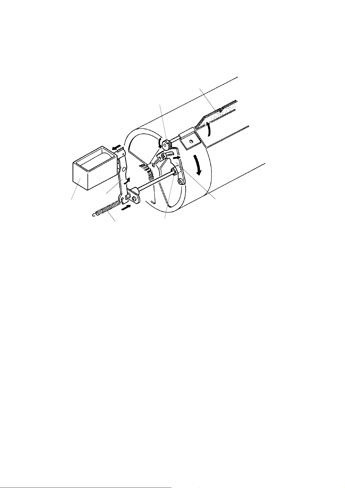
4.3 FEED ROLLER PRESSURE MECHANISM
[B]
[A]
[C]
[D]
C223D606.img
Due to the weight of the feed roller assembly [C], the paper feed roller
presses the paper stacked on th e pa per t ab le. This is because the feed roller
assembly rotates freely around its shaft [D].
The spring [A] applies t en sion to th e feed roller assembly in the directio n in
which the paper feed roller is pulled up. When the feed pressure lever [B ] is
moved up, the spring [A] is stre tch ed . Thu s, the tension of the spring is
increased, weakening the feed roller pressure.
Originally, the feed pressure lever is in the up position. When thick paper
(132.5 to 21 5 g/m2, or 35.2 to 57 lb) is used and frequen tly pa pe r is not fe d,
push down the feed pressure lever. The feed roller pressure will increase.
2-29
Page 47

[C]
PAPER FEED 15 November 1995
4.4 PAPER SEPARATION MECHANI SM
[A]
[B]
[D]
[A]
[C]
[E]
[G]
[F]
[D]
C223D604.img
Pressure from spring [F] holds the separation plate [G] against the upper
separation roller. A rubber pa d on top of the sep ara tion plate allows only a
few sheets of paper to reach the lowe r sepa rat ion roller. If too many sheets of
paper are fed to the lower separation roller at the same time, the lower
separation roller may not be able to separate the sheets; it can separate only
two or three sheets of pap er.
Springs pull lever [A] and this push es up the lower separation roller [E]. Then
this roller presses the sheets to be fed again st th e uppe r sepa rat ion roller [B].
Also, the lower separation roller does not turn in the paper feeding direction.
(It turns in the opposite direction due to the one-way clutch bearings [D]
provided on both right and left sepa rat ion le vers [A ]. ) Wh en two or more
sheets of paper are fed , a bra ke force is applied to the lower sheets of paper
due to the friction between the paper and the lower separatio n rolle r. The n,
the sheets are sepa rated and one sheet of pap er is f ed to th e second feed
rollers.
The pressure between the upper and lower separation rollers can be
adjusted by changing the right and left separation pressure adjusting levers
[C] as follows (this is a user-level adjustment):
Levers Up: Separation pressure decreases.
Levers Down: Standard position.
When dog-eared or wrinkled prints are delivered, the separation pressure
should be decreased.
2-30
Page 48

15 November 1995 PAPER FEED
Fig. 2
"E"
Fig. 1
[C]
[A]
[B]
[A]
[C]
[D]
View from "E"
C223D523.img
[F]
[G]
C223D524.img
The lower separation roller [C] turn s slight ly (see the arrow in Fig. 2) due to
the one-way clutch bearings when pa pe r passe s through the roller. The lower
separation roller [C] and its shaf t [D] are pushed down slightly by the paper
[B] when the upper separatio n rolle r [ A] is feeding the paper (Fig.1). Just
when the paper is fed out from the rollers, the lower separation roller [C] and
its shaft [D] spring back again st rolle r [ A] (Fig. 2). This ro ta tes the lower
separation roller and ensure s tha t it will wear eve nly.
Four paper guide rollers [G] are th ere to red uce curl in the paper’s leading
edge, and to feed the pap er smoo thly to the guide plates. There are four
marks on the bracket [F] corresponding to the roller position s as shown in the
lower diagram.
2-31
Page 49

PAPER FEED 15 November 1995
[A]
[B]
C223D529.img
[C]
C223D530.img
The side pads [A] in the front and rear paper side guides prevent multiple
feed. These are especia lly u sef ul when thin paper is used. Afte r adjusting the
paper side plates to the prop er pa pe r width (so that they touch the pap er
lightly), move the front and rea r side pa d leve rs to th e right (as viewed from
the operation side of the machine). Normally, the pressure from the side pads
should be released by moving the levers to the left.
The separation pla te pressure can be adjusted to match the type of paper
being used. The plate which sup po rts the pre ssure plate spring [B] can be
moved up or down by turning th e eccentric cam shaft [C] (this is a
service-level adjustment only).
If multiple paper feed freq ue ntly occurs, the plate should be move d up .
If paper misfeeds frequently, the plat e should be moved down.
2-32
Page 50

15 November 1995 PAPER FEED
4.5 SEPARATION ROLLER PRESSURE RELEASE
MECHANISM
[A]
[B]
[C]
[D]
[E]
C223D605.img
When printing is finished or a misfe ed occurs, the paper table drive motor
rotates for 500 milliseconds to lower the paper ta ble. The paper on the paper
table moves down from the pape r fee d roller [ D] and the paper feed bracket
[A] is pulled down by its own weight.
At this time, the shaft [B] pushes down the left separation lever [C] and this
moves the lower separation roller [E] slightly downward.
This mechanism makes it easier to remove pa pe r caug ht between the upper
and lower separation rollers.
2-33
Page 51

PAPER FEED 15 November 1995
4.6 SECOND FEED ROLLER MECHANIS M
[A]
[J]
[B]
[I]
[H]
[C]
[D]
[E]
[G]
[F]
[K]
C223D531.img
Drive Mechanism
The main motor drives the lowe r secon d feed roller cam [A], which moves the
sector gear [C] back and fort h. The sect or ge ar [C] ro ta te s the lower second
feed roller [I]. A one-way clutch inside the feed roller gear [E] prevents the
roller from rotating in reve rse du ring the retu rn ha lf of the secto r gea r
movement cycle. The cam ro ta tes once per sheet of paper.
When the paper feed solenoid [G] turns on, it pulls link [F], the 1st paper feed
roller sector gear stopper [H], an d th e 2n d fe ed roller sect or ge ar sto pp er [K ].
The bearing [J] on the sect or ge ar moves along the cam surface. Whe n the
widest part of the cam come s to th e be arin g [J], the stopper [B] is relea sed
from the sector gear as a clearance is formed between the pin of the secto r
gear [D] and th e stopper [K].
When the feed roller gear turns counterclockwise, its rot at ion is not
transmitted to the lower second feed roller due to the one-way clut ch bearing
in the gear.
When the narrowest part of the second feed roller cam moves away from the
bearing [J], the sector gear turns counterclockwise and the feed roller gear
turns clockwise. As the rotation of the feed roller gear is transmitted to the
lower second feed roller, the lowe r second feed roller turns clockwise to feed
the paper to the drum.
2-34
Page 52

15 November 1995 PAPER FEED
[B]
[A]
[C]
[G]
[H]
[F]
[A]
[D]
[E]
C223D542.img
Release Mechanism
This mechanism releases the uppe r seco nd feed rolle rs [B] from the lower
one [G] after the press roller and the drum catch the paper leadin g edge.
The mechanism is made up of several parts. First, a cam which transmits
motion to a sector gea r [F ]; the n another cam [E] that is part of th e sect or
gear. This cam pushes a bearing [D], which causes the lever [H] attached to
this bearing to turn the upper feed roller shaft [C] so that the upper rolle rs
contact the lower rollers.
At the beginning of each cycle the upper and lower rollers are away fro m
each other. They come tog et he r half way through the cycle and at the end of
the cycle they separate again.
At first, the rollers are sep ara te, and the sector gear [F] is ready to start
moving clockwise. The bearing [D] on th e leve r [ H] is in cont act with the cam
[E] on the sector gear. As the gear turn s clockwise, it causes the cam to turn
the lever in the same direction (clockwise).
The lever then lowers the upper rolle r [B] . It doe s this by tu rning the roller’s
eccentric shaft [C]. The sha ft is a little off center, so when the shaft turns the
roller, the roller moves up or down.
2-35
Page 53

PAPER FEED 15 November 1995
When the cycle is halfway through, the secto r gea r has reached its maximum
clockwise position. Now the upper roller touche s the lower one and a pair of
springs [A] apply tension at each en d of the upp er rolle r. Unt il n ow th e lowe r
roller has not turned.
At this point, the paper arrives from the first paper feed rollers. The leading
edge hits the two rollers and the paper buckles slightly. This ensu res th at the
paper will go into the rollers straight.
The lower roller now begins turnin g and feeds the paper to the drum section.
The sector gear is now turning cou nterclockwise, raising the upper roller. The
gear returns to its original position and the cycle is now over.
Service Note
The paper buckles slightly as the leading edge of the paper arrives from the
first paper feed rollers before the second paper feed rolle rs start to turn. The
second feed roller start timing can be adjust ed to cha nge th e leading edge
margin. See "Removal and Adju stme nt : Se cond Feed Roller Start Timing".
2-36
Page 54

15 November 1995 PAPER FEED
4.7 PAPER TABLE SIDE ADJUSTMENT MECHANIS M
[B]
[A]
[C]
[G]
[D]
[F]
[E]
C223D532.img
The shaft [D] of the fine adjustment dial [F] is threa de d. The inside of the
sleeve [E] is also thread ed. The sleeve is fixed to the paper ta ble st ay [B ]
through a bracket [A] .
The paper table bracket [C] mounted under the table is fixe d to bot h en ds of
the adjustment dial shaft . Whe n th e adjust ment dial is turned clockwise, the
feed table bracket [C] and the paper table move to the right.
The indicator [G] fixe d to the bracket [A] shows how much the pap er table
has moved.
2-37
Page 55

PAPER FEED 15 November 1995
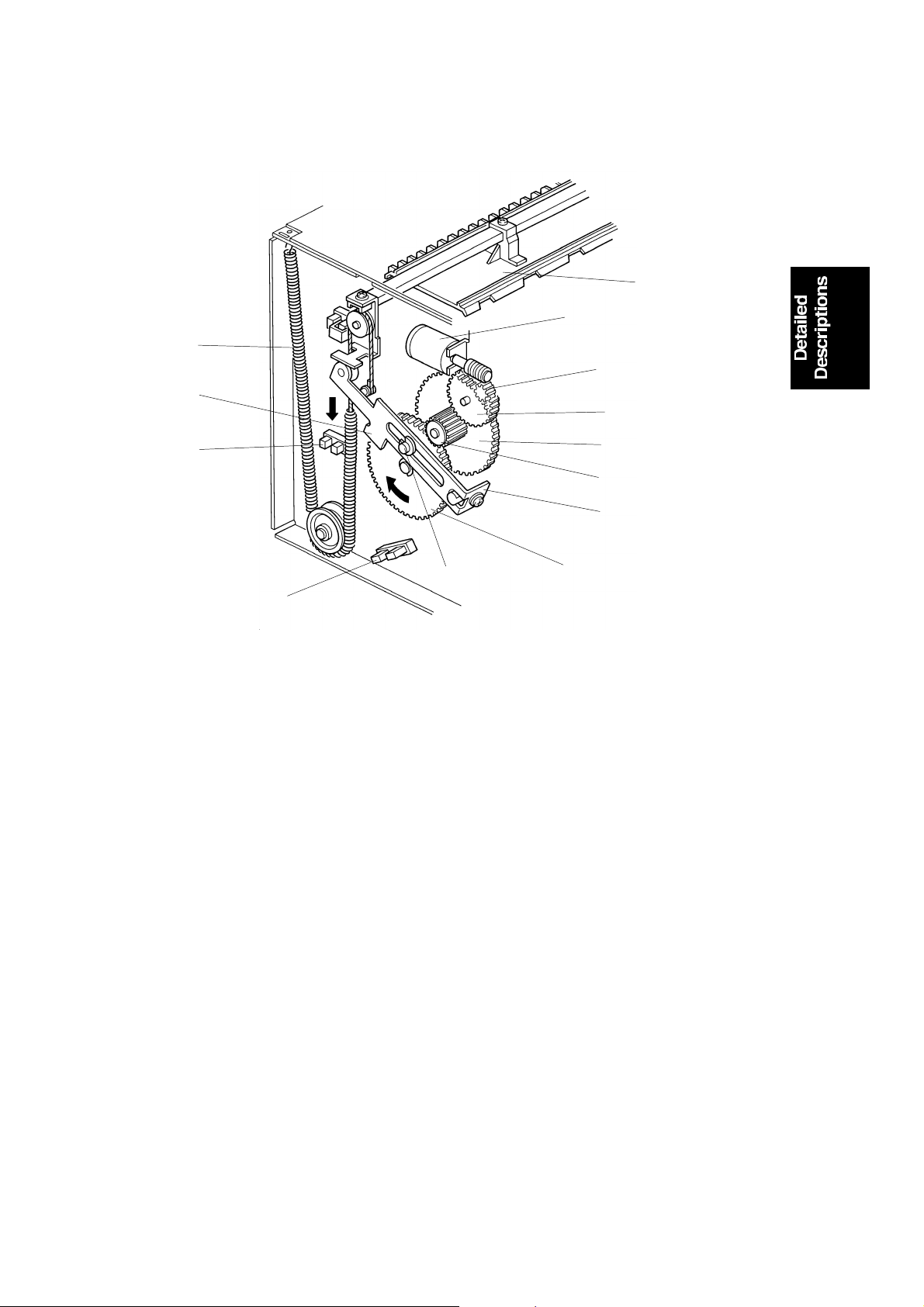
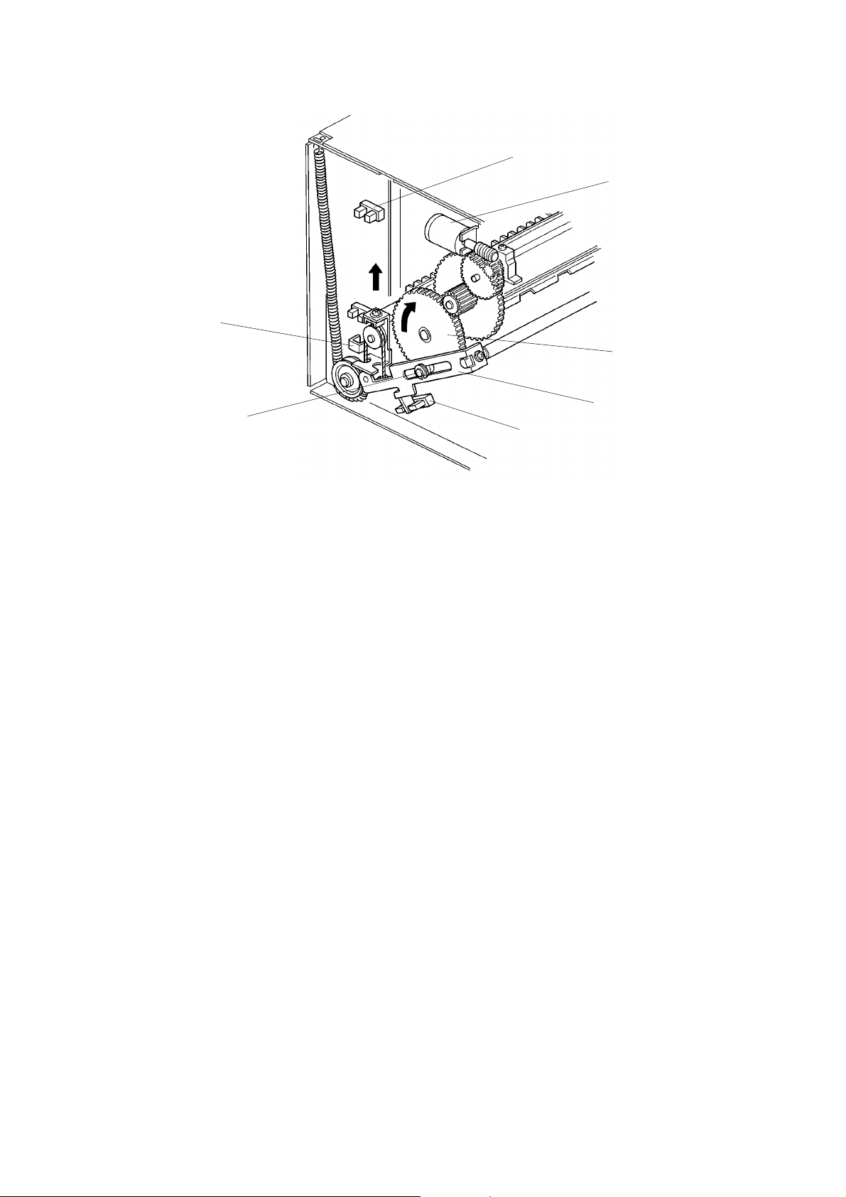
4.8 PAPER TABLE UP/DOWN MECHANISM
There are diagrams of this mecha nism on the following page.
The paper table is raised and lowere d by th e pa per t able drive motor.
The paper end sensor [E] (a reflective photosensor) is actuated when the
paper is placed on the paper ta ble. When the Print Start key is pre ssed , the
paper table drive motor [H] starts turning clockwise an d the worm gear [G ]
also turns. The gear [F] turns clockwise and both gears [D] turn to raise th e
racks [C].
As the paper table rises, the paper pushes against the paper feed roller [I].
This raises the lever [J] which is mount ed on the pa per f eed bra cket . This
activates the paper table height sensor [K] (the phototransistor detects the
light from the photocoupler, which up to now was cut off by the lever), and
that causes the paper t ab le mot or [H] to turn off and stop raising the paper
table.
As printing proceeds and the paper level runs down, the lever [J] cuts off th e
light path in the photocoupler and the motor [H] turn s clockwise until th e
phototransistor is react ivat ed . As a resu lt, the top of th e pa per st ack is
constantly kept at the correct heig ht .
When no paper is present, the pap er en d sensor [E] is not activated and the
motor [H] turns counterclockwise to lower th e paper table. The paper table is
lowered until the actuator [A] (fixed to the front rack) interrupts the lower limit
sensor [B].
When a misfeed occurs or printing is finished, the paper table motor [H] turns
counterclockwise for 500 milliseconds, slightly lowe ring the paper table.
2-38
Page 56

[A]
[D]
[H]
[G]
[J]
[K]
15 November 1995 PAPER FEED
[B]
[D]
[C]
[F]
[E]
C223D533.img
[I]
C223D534.img
2-39
Page 57

PAPER FEED 15 November 1995
4.9 PAPER SIZE DETECTION
The machine determines the printing area of the ma ste r based on the
detected paper size and th e original length (which is detected during the
original scanning process). If th e original size is different from the paper size,
the machine compares the lengths of the original and the paper. The
master’s length will be the shorter of the two. The prin ting width of the master
is determined by the paper width.
Note: The determined master printing area is not changed if the paper on
the paper table is replaced with another size of paper during the
master making process.
The printing area of the maste r for ea ch dete cted paper size is as follows:
Paper Size Printing Area of the Master
Width (mm) Length (mm)
A3
B4
A4
A4-S
B5
B5-S
A5
DLT
LG
LT
LT-S
HLT
292
256
208
292
180
256
146
278
214
214
278
138
412
356
289
202
249
174
202
412
348
271
208
208
S: Sideways feed
The machine can only distingu ish sta nd ard sizes. If a non-standard paper
size or original size is used, the mach ine will dete rmine a stan dard size for
the non-standard sized paper or original. If the actual paper size, the
non-standard sized paper, or the original is larg er than the determin ed paper
size, the excess area will not be tran sferred to the master. In such a case,
paper size detection can be can cele d using SP mode (no. 142-1) in order to
obtain the entire image of the origin al. However, the press roller may become
contaminated with ink if the paper is smaller than the image on the maste r.
The ink will be transferred to the back side of th e prints when the next printin g
is done with larger paper.
2-40
Page 58

[B]
15 November 1995 PAPER FEED
Paper Size Detection for the Pape r Tabl e
[B]
[A]
[A]
[G]
C223D566.wmf
[F]
[E]
[D]
[C]
C223D536.img
The paper width det ection plate [A] behin d the front paper side guid e [B] has
several interrupters.
The front and rear paper sid e gu ide s ar e adjusted to the paper width.
Depending on which paper width sen sors ([C] [D] [E ] [F]; 4 photointerrupters)
are interrupted and whet he r t he pape r len gth sensor [G] (a reflective
photosensor) is activated, the machine determines the paper size as shown
in the table below.
Paper Size A4-S LT-S B5-S LT A4 B5 A5 HLT A3 DLT B4 LG
Paper Width Sensor-0 [C] o x o x x x o x x o o x o x
Paper Width Sensor-1 [D] x o o x x x o o o o x o o x
Paper Width Sensor-2 [E] x x o o o o o x x x x x o o
Paper Width Sensor-3 [F] x x x x x o o o o o x x x x
Paper Length Sensor [G] x x x x x x x x x x o o o o
x: Not blocked or Not activated, o: Blocked or Activat ed
S: Sideways feed
2-41
Page 59

[C]
PAPER FEED 15 November 1995
4.10 NOISE REDUCTION COVER
[A]
[A]
[A]
[B]
C223D621.wmf
C223D622.wmf
[D]
[E]
C223D623.wmf
The noise reduction co ver [A ] reduces the paper feed noise. When the paper
feed table [B] is in the paper feed position, there is a small clearance
between the paper st ack an d th e no ise reduction cover.
The noise reduction co ver can be fo lde d ba ck wh en a user puts pa pe r on th e
table. The magnet [C] catches the cover to keep it in the up pe r posit ion.
By loosening the screw [D], the bracket [E] can be slid in the arrow directio n
and the noise reduction cover can be removed from the machin e.
2-42
Page 60

Counter Reset
15 November 1995 PAPER FEED
4.11 ELECTRICAL TIMING
Stop key ON
30 ms
C223D537.wmf
500 ms
Paper Table Height Sensor
Paper Table Up Relay
(Table up)
Paper Table Brake Relay
First Drum Position Sensor
Second Drum Position Sensor
Paper Feed Solenoid
Vacuum Fan Motor
Air Knife Motor
Main Motor (Forward)
Paper Table Down Relay
Print key ON
15 ms
50 ms
T1: When paper is placed on th e pa pe r tab le an d the Print key is pressed, the
paper table moves up unt il the pap er ta ble height sensor is activated . 15
milliseconds after the height senso r is act ivat ed , th e paper t able brake
signal turns on for 50 milliseconds to apply bra king force to the paper
table drive motor to prevent th e pape r tab le fro m overrunning.
T2: When the height sensor is activated, the vacuu m f an moto r a nd air knife
motor turn on. At the same time, the drum (main mo to r) starts turning
forward (this is the printin g dire ctio n).
T3: The paper feed solen oid is energized when the interrupter at the rear side
of the drum activate s the secon d drum position sensor.
T4: After the paper is fed, the top of the pap er sta ck is a little lowe r and the
height sensor is de-activat ed . Whe n th e second drum position sensor is
activated, the paper table drive mot or sta rts rot at ing. This lifts the paper
table until the height sensor is re-activat ed (app roxima te ly 30
milliseconds after the motor starts). Whe n the heigh t sensor is
re-activated, the motor stops rotating.
T5: After the Stop key is pressed, the paper feed solen oid is de-energized the
next time that the second drum position sensor is activated. The coun te r
on the operation panel will be reset at this time.
T6: When the second drum po sition sensor is again activated aft er on e more
drum rotation, th e vacu um fan motor and air knife motor tu rn of f. Then,
the drum rotates once more and stops at the first drum position act uatio n
position (the drum home position).
2-43
Page 61

[A]
[C]
PRINTING 15 November 1995
5. PRINTING
5.1 OVERALL
[B]
C223D538-1.img
In standby mode, the printing pressure roller is held away from the drum by
two devices, a solenoid (the printing pressure solenoid), and a mechanical
arm (activated by the paper detect ion fee ler [A ]).
At the start of printing, the printing pressure solenoid releases its hold on the
printing mechanism at poin t [C], and the paper feed soleno id turns on to
transfer drive from the main mot or to the paper fe ed mecha nism.
Soon after the paper has reached the second paper feed roller, the paper
detection feeler [A] is pushed down by the paper, which completely rele ases
the printing mechanism.
Printing pressure is then applie d (th e press ro ller [B ] to uch es th e dru m) to
transfer the ink from the master to the printer pa per.
If the machine is not used for more than 8 hours, a drum stroke operation is
done before the master wrapped around the drum is removed. This operation
minimizes the wasted prints before the image is stabilize d.
2-44
Page 62

15 November 1995 PRINTING
5.2 PAPER DETECTION AND PRINTING PRESSURE ON/OFF
MECHANISM
Rear View
[F]
Front View
[F]
[E]
[D]
[H]
[C]
[B]
[G]
[A]
C223D538-2.img
C223D540.img
During the printing process, the main motor turns the gear [A] and pressure
cam [B] clockwise.
When the widest part of th e pressure cam [B] reaches the be aring on the
pressure on/off lever [C], th e pape r det ect ion arm [D] separates from the
pressure on/off lever [C] . At this mome nt, if paper is being fed, the paper
presses down the paper detection feeler [E]. The n, the pap er de tection arm
[D] turns clockwise to release the pressu re on/o ff le ver. As a result , th e
pressure on/off bea ring continues moving along the pressu re cam an d the
press roller [F] moves against the drum to apply p rint ing pressu re.
The printing pressure can be adju sted with the pressure spring [G].
The printing pressure sensor feeler [H] is away from the sensor while printing
pressure is applied.
2-45
Page 63

[H]
[E]
PRINTING 15 November 1995
5.3 PRINTING PRESSURE RELEASE MECHANISM
[A]
[B]
[G]
[C]
[D]
C223D538-3.img
[F]
[D]
C223D539.img
During normal operation , th e printing pressure solenoid [G] energize s to
release the pressure on/ of f leve r [ D] at the same time as the paper feed
solenoid energizes.
If a jammed sheet of paper in the printing sectio n pre sses do wn on the paper
detection feeler [A], the pressu re on/off lever [D] remains disengage d fro m
the paper detection arm [C]. Printing pre ssure will keep on bein g applie d to
the drum. If this printing pressure is still applied when an opera to r slides out
the drum unit to remove the jammed sheet, the drum surface and the press
roller could be damaged.
To prevent this, printing pressure is released from the drum if a paper
misfeed is detected. When a misfeed is detected, the print ing pressu re
solenoid [G] is de-en erg ized. Then, the drum rotates to the home position.
While the drum returns to the home position, the widest part of the pressure
cam [F] approach the bearing [E] . This move s the pressu re on/off lever [D]
clockwise, then the stopp er [H] eng ag es th e lever [D] (because the stopp er
[H] is pressed down by spring tensio n fro m the solen oid ). Thus, printing
pressure is released since th e leve r [D] is co nnected to the press roller [B].
2-46
Page 64

[B]
15 November 1995 PRINTING
5.4 QUALITY START OPERATION
[D]
[E]
C223D557.wmf
[C]
[C]
D223D558.wmf
If the main motor has been kept off for more tha n 6 hours, a drum stro ke
operation is done before the master wrapped around the drum is removed.
This operation removes the dried ink with the ejected master to minimize th e
waste prints before the print image is stabilized.
[A]
When the master making key is pressed , th e master press sheet solenoid [A]
is energized. The master press she et mylar [B] is inserted between the drum
and the press roller [C]. At the same time, the det ect ion arm release solenoid
[D] is energized to relea se th e pa pe r det ection arm [E]. Then, the ma in mot or
turns on and the press roller presses the mylar she et to stroke th e dru m
surface. The drum ro ta tes twice (three times if the machine is kep t of f for
more than 32 hours) to stroke the master around the drum. Then the master
press sheet solenoid and the detection pin release solenoid are de-energized
and the master eject operation starts.
There is no paper in the paper path at this time to rele ase the paper detection
arm [E] so that printing pressure can be applied to the master press sheet
mylar [B], so the extra soleno id [D] was add ed to the mechanism.
2-47
Page 65

PRINTING 15 November 1995
5.5 ELECTRICAL TIMING
C223D556.wmf
T1: The main motor starts. At the same time, the printing pressure soleno id
and the detection arm release solenoid turn on.
T2: When the drum has rotated 198 degree s f rom the ho me position, the
master press sheet solen oid turns on. The solenoid tu rns of f when the
drum has rotated a further 40 degrees.
T3: When the printin g pressure sensor turns on afte r t he maste r p ress she et
solenoid has been energized (n-1) times, the printing pressure solenoid
and the detection arm release solenoid turn off.
The value of "n" depen ds on SP79 and 80.
2-48
Page 66

[B]
15 November 1995 DRUM
6. DRUM
6.1 OVERALL
[C]
[A]
[F]
[E]
[D]
C223D541.wmf
[A]: Doctor Roller
[B]: Ink
[C]: Ink Roller
[D]: Press Roller
[E]: Pa per
[F]: Drum
Ink is supplied from the ink cartridge and is applied to the ink roller unif ormly.
The ink is then transferred to the print ing paper th rough the holes in the
master.
2-49
Page 67

[H]
DRUM 15 November 1995
6.2 DRUM ROTATION MECHANISM
[B]
[A]
[C]
[D]
[B]
[A]
[E]
[F]
[K]
C223D574.img
[J]
[I]
[G]
C223D575.img
The main motor (a dc moto r) [J], located under the rear sid e pla te, turns the
drum either clockwise or counterclockwise throu gh belt [G] , then throug h
gears [F] and [E], then belt [D] , and pu lley [C] . The drive mechanism uses
helical gears because they turn more quietly.
Notice gear [A], th e last gea r of the drive, and gear [B] at the rear en d of the
drum: they each have a part cut out of the flange [K]. When the drum is in the
home position, the cutou t parts meet, and the drum unit can be pulled out.
Pulse disk [I] and sensor [H] on the main motor shaft monitor the dru m
rotation speed.
2-50
Page 68

15 November 1995 DRUM
6.3 DRUM LOCK MECHANISM 1
[E]
[C]
[A]
[B]
[C]
Fig. 3
[B]
[B]
[D]
[B]
[C]
[C]
C223D544.img
[D]
Fig. 1
[D]
Fig. 2
C223D543.img
When the drum unit is placed in th e mach ine, the arm [B] is pushed by the
lock pin [D] until the top of the arm [B ] is locked by the stoppe r [C]. This
completely locks the drum unit in th e mach ine (Fig . 1). At th e same time, the
top of the right stopper [C] turn s on the dru m d etection switch [E]. The switch
[E] tells the machine that the drum unit is in place (Fig. 3).
Pulling the lever [A] to th e operation side turns the stopper [C] clockwise and
disengages the arm [B]. Theref ore, the lock pin [D] of the main body is also
released from the arm [B ] du e to sp ring ten sion (Fig . 2).
2-51
Page 69

DRUM 15 November 1995
6.4 DRUM LOCK MECHANISM 2
[B]
[C]
[B]
[A]
[A]
C223D545.img
To prevent the drum from ro ta ting when the drum unit is slid out, the drum
stopper [A] drops into the drum lock [B]. This secures the drum [D].
[D]
When the drum unit is put back, the front side plat e of the main body [C]
holds the drum stopper [A] out of the drum lock.
2-52
Page 70

[B]
15 November 1995 DRUM
6.5 DRUM LOCK MECHANISM 3
[A]
[B]
[C]
[D]
C223D546.img
C223D547.img
When the drum is pulled out, the drum sto pp er [B ] drops into the hole (see
the above diagram). This stops th e drum unit from be ing pulle d out an y
further. Now, if the operator pu lls han dle [A] , th e dru m unit won’t fall out.
When the operator pulls stopper release [D] in the direction of the arrow, the
drum stopper [B] is pushed up to the level of the drum rail cover [C]. This
allows the drum to be removed.
2-53
Page 71

[E]
DRUM 15 November 1995
6.6 DRUM CONNECTION MECHANISM/DRUM LOCK
MECHANISM 4
[D]
[A]
[C]
[B]
[F]
C223D548.img
[D]
[H]
[G]
C223D549.img
When the drum release lever [A ] in front of the machine is raised, the
connector [B] is push ed away fro m t he drum by th e bra cket [C] through the
link [D], and is disconnected. The bracke t [C] also pu she s the drum lock leve r
[F] to release the dru m lock allowing the drum to be removed. Wh ile th e drum
is away from its home position, the drum lock sole noid [G] is energized and
the stopper [H] locks the link [D] to prevent the drum from be ing pulle d out
during a print cycle. The sole no id is de-energized when the drum stop s at the
home position (when the 1st drum position sensor is actuated).
2-54
Page 72

[J]
[K]
15 November 1995 DRUM
6.7 INK SUPPLY MECHANISM
[A]
[M]
[B]
[L]
[C]
[D]
[E]
[F]
[G]
[H]
[I]
C223D550.img
Ink is supplied from the ink cartridge [H] to the ink roller [M] by the ink pump
[I] and then through 8 holes in the ink distributor [A].
Drum rotation is transmitted from gear [K ] to gear [L] , then to the gear of the
spring clutch [G]. However, the rotation is not transmitted to gear [D] because
of the spring clutch [G].
When the ink detector detects less ink on the ink roller [M], the ink sup ply
solenoid [E] turns on, and the ink supply stopper [F] releases clutch [G]
allowing the gear [D] to turn.
The pin [C] moves the pump shaft up and down as the gear [D] rotates. (One
stroke of the ink pump occurs for eve ry 2 rotations of the drum.) Therefore,
the ink in the ink cartridge is sucked into the pump [I]. The pump then sends
the ink out into the drum shaft [J]. Then , th e ink goes fro m the ink distrib ut or
[A] onto the ink roller [M] through the tub e [B ].
2-55
Page 73

DRUM 15 November 1995
6.8 INK KNEADING MECHANISM
[C]
[A]
[D]
[A]
[E]
[B]
[C]
0.08 mm
[B]
[F]
C223D551.img
The ink kneading mechanism con sists of the ink roller [C] and the doctor
roller [B]. The ink roller [C] rotates with the drum and the docto r ro ller [B ]
ensures that the ink goes evenly to th e ink rolle r.
The ink roller [C] rotates with the drum this way: the dru m turn s a gear [A] ,
the gear [A] turns an idle gear [E], and the idle gear [E] turn s the roller ge ar
[D]. The gear [D] is mounted on the ink roller.
The doctor roller is adjusted to give a distance of 0.08 millimet er betwe en
itself and the ink roller. It rotat es to create an even thickness of ink.
The ink roller does not touch the scree n [F] wh en the machin e is not print ing.
However, during the printing proce ss, the ink on the ink roller goes to the
paper through holes in the screen and the master. This happens while the
drum screen is held against the master by the pressure roller located under
the drum.
During the master eject process, the drum rotates in the reverse direction but
the ink roller does not rotate at all; the gear [D] has a one-way clutch to
prevent that.
2-56
Page 74

15 November 1995 DRUM
6.9 DRUM MASTER DETECTION
[A]
[B]
[B]
[C]
C223D552.img
The drum master sensor [A] is mounted on the drum rail and it detects
whether a master is on the drum.
When there is a master on th e dru m, the black patch [B] is covered an d th e
sensor detects the light reflected from the master [C]. Printing starts when the
Print Start key is pressed.
When there is no master on the drum, the black sea l is exposed. The black
seal does not reflect light back to the senso r. The "M" indicator on the display
panel blinks and printing does not start when the Print Sta rt key or th e Proof
key is pressed.
2-57
Page 75

DRUM 15 November 1995
[B]
C223D616.img
[A]
View from the operation side
Terminal Numbers
C223D618.img
The machine identifies th e drum type electrically. Depending on which
terminals of the drum unit connecto r [A] are con ne cte d, the corresp on din g
indicator lights up on the operation panel as follows:
[C]
Drum Type Indica to r Terminal Number
2345
A3/DLT (Original)
A3/DLT (Option)
A4/LT (Option)
A3 or DLT Indicator
A3 or DLT and Color Indicators
A4 or LT Indicator
1
1
1
0
1
0
1
1
1
0
0
1
1: Connected, 0: Not connected
To use the A4/LT drum with color ink, termin als no. 2 and no . 3 should be
linked using a short connector [B]. This will turn on the color indicator. The
short connector is an accessory of the unit , an d is included with it.
NOTE:
To use the A4/LT drum with black ink, it is not necessary to use
*
short connector [B].
To use a 1000 cc black ink cartridge with the drum, the ink holder
*
spacer [C] must be removed. The ink holder spacer is originally
installed in the optional A3 /DL T and A4/ LT dru ms and is
necessary only for the 600 cc ink cartridges.
2-58
Page 76

T0
T2
THRESHOLD
TRIGGER2
THRESHOLD2
[B]
15 November 1995 DRUM
6.10 INK DETECTION
OUTPUT1
OUTPUT2
Main PCB
Ink Detection PCB
[C]
Ink Detection Circuit
[A]
(1) Standard Pulse
(2) Detection Pulse
(3) Output of CN902-2
Ink is present No ink is present
C223D553.wmf
T0
T1
C223D554.wmf
The detecting pin [B] works like the elect rod e of a capacito r. The capacitance
between this pin and the ink roller [C] depe nds on th e pre sen ce or ab sen ce
of ink, and it affects the dut y cycle of th e de tection pulse generated by the ink
detection PCB. The de tection pulse is compared to a sta nd ard pulse to
detect whether there is ink in the drum or not.
(1) The standard pulse is output from OUTPUT 1. The pulse length (T0) can
be adjusted by adjusting VR901.
(2) OUTPUT 2 is the detection pulse. The duty cycle is determined by C908
and the electrostatic capacity between the detect ion pin and the ink roller
[C] or doctor roller [A] (ground). The detection pulse is triggered by the
falling edge of the sta nd ard pulse tha t is in put from TRIGGER 2.
When ink is present, the electrostatic capacity increases and the pulse
length (T1) becomes longer. On the other hand, when ink is not pre sent,
the pulse length (T2) becomes shorter as the electrostatic capacity
decreases.
(3) The pulse length (T1 or T2) is compared wit h th e standard pulse (T0).
When the pulse length is shorte r tha n th e sta nd ard pulse (T 0 ), the output
of CN902-2 goes low, indicating that there is no ink.
2-59
Page 77

DRUM 15 November 1995
20 drum rotations
2nd Drum Position Sensor
T1
No Ink Signal (CN902-2)
Ink Supply Solenoid
T2
No Ink Indicator
C223D555.wmf
Ink Detection Timing
T1: When there is no ink left on th e ink rolle r and the no ink signal (ou tp ut of
CN902-2) is low (indicating that there is no ink), the ink supply solenoid
turns on at the next rising ed ge of th e second drum position sensor
signal. The ink supply solenoid turns off when CN902-2 goes high.
T2: If the no ink signal remains low whe n the drum has made 20 rotatio ns
since the ink supply solenoid turned on, the No Ink indica tor blinks.
When this happens and when the "Rese t" key is pre ssed , the drum turns
40 times to supply ink; this is the user’s proced ure for sup plying new ink.
(When the "0" key is pressed while pressing the "Rese t" key, the drum
turns 40 times even when the No Ink ind icat or is n ot blinkin g: this is a
technician’s test procedure.)
When the No Ink Signal goes high durin g the 40 drum rot ations, the
indicator goes off and the ink supply solenoid is de-energized.
2-60
Page 78

[D]
[E]
15 November 1995 DELIVERY
7. DELIVERY
7.1 OVERALL
[A]
[B]
[C]
[H]
[G]
[F]
C223D601.wmf
[D]: Belt
[F]: Vacuum Fan
[G]: Press Roller
[H]: Paper
The exit pawl [C] and the air knife [B] separate the paper from the dru m [A]
and the vacuum fan [F] in the transp ort unit [E] pulls th e paper a gainst the
belt [D] as the belt moves the paper to the delivery table.
2-61
Page 79

DELIVERY 15 November 1995
7.2 EXIT PAWL DRIVE MECHANISM
[A]
[B]
[C]
[D]
[H]
[G]
[E]
[F]
C223D607.wmf
The exit pawl [B], located in the cent er of the drum, guid es th e cen te r of th e
printing paper. As the master clamper [A] approaches the exit pawl, the exit
pawl moves away from the drum.
When printing pressure is applied to the drum, th e narrowe st part of the
pressure cam [G] comes to the bearing on the pressure on/off lever [H] , and
the lever [H] turns counterclockwise. The exit pawl drive cam [F] is connected
to the pressure on/of f leve r [ H] an d so th e cam [F] moves up. The exit pawl
lever [E] then turns clo ckwise as it move s along the surface of the exit pawl
drive cam [F]. Therefore, th e exit pawl also comes near the drum until the
stopper [D] contacts the adjusting screw [C]. This keeps a small clearance
between the exit pawl and the drum surface to ensure the prin tin g paper will
be fed to the vacuu m unit.
As the press roller moves away from the dru m (t he widest part of the cam [G]
comes to the bearing on the pressure on/off lever [H]), the exit pawl drive
cam [F] moves down and the exit pawl lever [E ] tu rns counterclockwise. This
causes the exit pawl [B] to separa te from the dru m.
The exit pawl [B] is held away from the drum whe n printing pressure is not
applied.
2-62
Page 80

15 November 1995 DELIVERY
7.3 VACUUM UNIT DRIVE MECHANISM
[A]
[F]
[B]
[E]
[C]
C223D608.wmf
The vacuum fan (below th e transport belts) holds the pape r ag ain st the
transport belts [D]. The tran spo rt be lts move the paper to the delive ry tab le.
Wing guides [C] at each end of the vacuum unit he lp keep the back side of
the printing paper clean.
When the main motor turns on , th e ge ar [F] mounted on the main motor shaft
drives a drive shaft [E] through gea rs and belt s. This drive shaf t tu rns th e
transport belts.
The first and second paper exit sensors [A ] an d [B ] che ck for pa pe r jams.
The paper exit jam check is done when printing pressure is applied and the
printing pressure sensor is interrup te d.
Jam Condition Sensor Status
Delivery Misfeed The 2nd paper exit sensor is still on when the 2nd drum position
sensor turns on.
Paper Wrap The 1st paper exit sensor fails to turn on even though the drum has
rotated 20° after activating the 2nd drum position sensor.
Paper Wrap The 2nd paper exit sensor fails to turn on even though the drum has
rotated 25° after activating the 1st drum position sensor.
[D]
2-63
Page 81

DELIVERY 15 November 1995
7.4 EXIT PAWL AIR PUMP MECHANI S M
[C]
[B]
[D]
[A]
C223D609.img
The main motor [A] turns a gear [B] thro ug h idle gears, a belt an d a shaft.
The gear [B] rotates an d drive s t he pisto n [C] back an d fo rth.
The piston moves forward and pushes a jet of air out through the nozzle [D].
This jet of air helps push down on the pape r and sepa rat es it from the drum.
2-64
Page 82

15 November 1995 DELIVERY
7.5 WING GUIDE MECHANISM
[A]
[B]
C223D620.img
The wing guide [A] lift s up th e sides of the paper as it exits the mach ine .
This stiffens the paper so that the leading edge of thin paper will not sag and
brush against the sheets on the delivery table. This prevents the ink on
freshly printed sheets from b ein g smea red.
The angle of the wing guide can be changed by moving the guide release
lever [B]. Usually, the wing gu ide release lever is set to the lower position to
raise the wings. If print ed pages do not stack evenly or if the pages pass over
the end fence, raise the lever to the upper position to rele ase the wings.
2-65
Page 83

[E]
DELIVERY 15 November 1995
7.6 PAPER DELIVERY TABLE
7.6.1 Master Eject Unit Lock Mechanism
[A]
[D]
[D]
[G]
[H]
C223D578.img
[B]
C223D559.img
The master eject open but to n [A ] locks whe n the paper delivery table is
closed. This prevents th e pa pe r delivery table from opening sud de nly whe n
the user presses the master eje ct op en but to n.
This lock mechanism functions as follows:
• As the paper delivery table is closed, the pin [B ] located on the front of the
paper delivery table pushes down on lever [ C] which raises arm [D]. When
arm [D] is in the upper position, leve r [E] cann ot move forward.
[F]
[C]
• When the delivery table is opened, arm [D] is pulled do wn by th e tension
spring [F] and lever [E] can move forward .
• The projection [G] on arm [D] contact s the delive ry t able op en switch [H] ,
which sends a signal to inform the main PCB that the delivery table is
open.
2-66
Page 84

15 November 1995 DELIVERY
7.6.2 Paper Delivery Table Angle
[B]
[B]
[C]
[A]
[C]
[A]
[A]
Fig. 1: Closed
[C]
Fig. 3: LevelFig. 2: 10° slant
C223D560.img
There are two paper delivery table open positio ns.
As the paper delivery table is lowered from the closed position (fig . 1), the pin
[A] fixed to the table side frame moves forward and pu she s t he st op per [ B]
forward. This disengages the lever [C] from the stopper (fig. 2) with a audible
click and the table stops at a 10° downward slant when the pin rea che s t he
end of the slot cut in the side frame.
When the delivery table is slightly raised up from the 10° downward slant
position, spring te nsio n pu lls the le ver downward and the pin engages th e
lever. This stops the table at the level position.
Normally, the table should be at a 10° downwa rd slan t. This prevents the
leading edge of each sheet from rubbing against the other sheets on the
table as the sheet is fed out, and ensures that the le ad ing edg e of the sheet
being fed out will not smear the ink on the top print out th at is on the pape r
delivery table. However, small she et s of pa per sh eets may pa ss over th e en d
fence if the table is at the 10° do wnward slant position. If this hap pe ns, the
user should raise the ta ble to th e level position.
2-67
Page 85

DELIVERY 15 November 1995
7.7 ELECTRICAL TIMING
1st Drum Position Sensor
(Home Position 1)
2nd Drum Position Sensor
(Home Position 2)
Cutter Motor
Vacuum Fan Motor
Air Knife Motor
Paper Feed Solenoid
Printing Pressure
Sensor
1st Exit Sensor
Main Motor
Paper Tabel Height
Sensor
Paper Table Drive
Motor
Cutter Motor ON
T1
10rpm
T5
60rpm
T2
10rpm
Print Key ON
T3
Stop Key
ON
Counter "0"
T4
C223D561.wmf
T1: The cutter motor, vacuum fan motor, air knife motor, and main mot or tu rn
on.
T2: The vacuum fan motor and the air knife motor turn off the next time the
2nd drum position sensor is deactivated after the print ing pressu re sen sor
turns off.
T3: When the Print St art key is pressed, the vacuum fan motor and the air
knife motor turn on whe n the paper table height sen sor is activated.
T4: When the count er indicates "0" and the 2nd drum p osit ion sensor is
activated, the vacuum fan motor and air knife motor turn off.
T5: When the 1st exit sen sor an d th e printing pressure sensor turn off, the
main motor speed increases to 60 rpm to ensu re pape r delive ry t o th e
exit table.
2-68
Page 86

[A]
[F]
[G]
[B]
15 November 1995 IMAGE POSITIONING
8. IMAGE POSITIONING
8.1 OVERALL
In image positioning mode, the image can be shifted 20 mm (5 mm steps) up
and –15 mm down on the page by pressing the forward or ba ckward Image
Position key on the operatio n panel. This rotates the first and second paper
feed roller cam a small distance to change the paper feed timin g in relatio n to
the drum rotation timing.
8.2 IMAGE POSITIONING MECHANI S M
[H]
Continued on the next page
[C]
C223D562.img
2-69
Page 87

IMAGE POSITIONING 15 November 1995
[C]
[D]
[E]
[G]
C223D563.img
When the forward Image Posit ion key on th e opera tion panel is pressed, the
image positioning motor [A] turn s and drives cam gear [B ] clockwise a short
way through gears.
The cam gear has a spiral track along which the lever [C] mo ves. When the
cam gear turns clockwise a short way, the pin on the lever [C] mo ves to ward s
the outside of the cam gear and th e leve r turns clockwise a short way.
The lever [C] drives gear [E] clo ckwise a sho rt way th rough gear [D] and the
first paper feed roller and the second paper feed roller cams [F] mou nt ed of
the shaft on gear [G] turn clockwise a sho rt dist an ce.
As a result, the paper feed start timin g is dela yed in relat ion to th e dru m
rotation timing and the image position is moved in the forwa rd dire ctio n.
(Refer to the Paper Feed section for details on the cam mechanism. )
The image position is detected by the image position senso r [H] which is
located behind the cam gear [B].
2-70
Page 88

15 November 1995 IMAGE POSITIONING
8.3 CIRCUIT
Main PCB
Image
Position
Image Position
Motor
C223D564.wmf
When the forward Image Position key is pressed, CN103-2 goes to 22 V and
CN103-1 goes to 0 V, and the image positionin g mot or tu rns to adva nce the
paper feed timing.
Sensor
When the backward Image Position key is pressed, CN103-1 goes to 22 V
and CN103-2 goes to 0 V, and th e imag e po sitioning motor turns to move
back the paper feed timing.
The main PCB detects the image position by means of a four-bit signa l
received from the image position sensor. The image positioning motor turns
off when the image is at the selected position.
Nine different imag e po sitio n settings can be selected by pre ssing the Image
Position key.
COM
Shaft
b4
(+) (+)
12345678910111213141516
01326754CDFEAB98
b10110011001100110
b20011110000111100
b30000111111110000
b40000000011111110
Not Used
b3
b2
b1
Image Position Area
0
1 = Switch is on
0 = Switch is off
C223D600.wmf
2-71
Page 89

IMAGE PROCESSING 15 November 1995
9.
IMAGE PROCESSING
9.1 OVERVIEW
Analog signal
A/D Conversion
PCB
6-bit
Image Processing
PCB
Main Control
PDB
Image Setting
Operation Panel
C223D579.wmf
Thermal Head
CCD PDB
1-bit
Thernal Head
Drive PCB
The light reflected from the origin al goes to the CCD, which converts the light
signal into an analog elect rical sign al. The analog signal is sent to th e A/D
conversion PCB, where it is changed to 6-bit digit al da ta . The 6-bit dat a is
changed to 1-bit data in the ima ge proce ssing PCB and the image
processing PCB drives the thermal head through the thermal he ad drive PCB
to make an image on the master with the 1-bit data.
The 6-bit to 1-bit conversion procedure depends on the image setting s on the
operation panel.
2-72
Page 90

15 November 1995 IMAGE PROCESSING
9.2 CCD (CHARGE COUPLED DEVICE)
The light reflected from the origin al rea ches the CCD (Charge Coupled
Device). The CCD reads one complete scan lin e at a time.
The basic circuit of each CCD element is shown below. The light ref lect ed
from the original is detected by a photo dio de . A cap acitor stores the resulting
electrical charge, which depend s on the ligh t int en sity. Th e CCD used in this
model has 5416 sets of such photodiodes and capacitors in series. The
electrical charges from the CCD ele men ts are sent to th e A/D co nve rsion
PCB one after the othe r (this is t he OS signal). To increase the scanning
speed, the odd and even pixel data are handled separately.
The CCD consists of 5416 elements. The first 64 elements are dummy
elements which are not used for image data. The followin g 5340 pixels are
effective element s. All th e da ta for one scan line across the origin al imag e
are converted into electrica l charg es an d sto red in the capa cito rs of th ese
elements. After the effe ctive eleme nt s, th ere are 12 more dummy e leme nt s.
2-73
C223D580.wmf
Page 91

IMAGE PROCESSING 15 November 1995
9.3 A/D CONVERSION
C223D581.wmf
The analog signal generated from the CCD is inverted and amplified in the
A/D conversion PCB. The an alo g signal is converted into 6-bit digital data
which is sent to the image processing PCB. The original background and the
distortion of the ligh t pa th are mon itored to obtain accurate image data.
2-74
Page 92

15 November 1995 IMAGE PROCESSING
9.3.1 Inversion and Amplification
C223D582.wmf
The analog signal (OS) from the CCD is out put to the A/D con version PCB. It
is sent as a negative signal in relation to the dc bias volt age (which is
approximately 4.8 V). In the A/D conversion PCB, the negative sign al is
inverted and amplified be fo re be ing converted to digital.
The amplification ratio can be chan ge d usin g VR601 on the A/D conversion
PCB.
9.3.2 A/D Converter
The inverted and amplified CCD output is sent to the A/D con vert er. The A/D
converter can produce 64 gra y scale steps. To make the 64 steps, th e
difference in voltage betwe en the high refe ren ce voltage (+REF) and the low
reference voltage (-REF) is divided into 64. The amp lifie d CCD out put volt age
is digitized based on these ste ps. If the amplified CCD outpu t volt ag e is
higher (the image pixel is lighter), a higher value is the result.
The digitized image data are sent serially to the main con trol PCB.
2-75
C223D583.wmf
Page 93

IMAGE PROCESSING 15 November 1995
9.3.3 Shading Distortion Correction
The image data from one main scan line sen t from the CCD does not exactly
represent the line fro m the origin al image, because of the following reasons:
1) Loss of brightness towards the ends of the exposure lamp an d the edges
of the lens.
2) Variations in sensitivity among element s of the CCD
3) Distortions of the light path
Such distortions in the image dat a are correct ed when the y are con vert ed
into digital data.
Before scanning the document, the scanner reads the white plat e on the
back of the original scale. The output of each CCD eleme nt is cha nged to a
6-bit digital value and store d in the sha ding distortion memory.
To change the analog sha ding distortion signals to digital data, a scale of 64
steps is made between the whitest level when the white plate is scanned and
50% of the whitest level. Using this scale, the analog signal is ch an ged to
6-bit digital data.
While an original is scanned, the 6-bit shading distortion value for each pixel
is serially sent from memory to the D/A converter, synchronizing with the
image signal being sent to th e A/ D co nve rter. The D/A converter chang es th e
distortion value to electrica l current. The current is converted to the voltage to
be used as high reference da ta for A/D conversion. In this way, the high
reference voltage for A/ D conversion is changed serially for each pixel
depending on the shading distortion data for t hat pixel.
2-76
C223D584.wmf
Page 94

15 November 1995 IMAGE PROCESSING
9.3.4 Original Background Correction
When an original is scanned, the whitest level of the original ba ckgro und is
stored, and that le vel is used as t he wh ite pea k level for A/D conversion. The
gray scale is made based on the white peak level of the origin al. As a result,
dark background does not appear on the printout.
In the normal setting, th e orig inal background correction is done for Lin e
mode only. In Photo mode or Line/Photo mode, the whitest level when the
white plate is scanned is used for the high reference voltage. If "Yes" is
selected in SP29, the ba ckground correction is also done for Ph oto and
Line/Photo modes.
C223D585.wmf
9.3.5 Peak Hold
The peak hold circuit holds the voltage for the white peak level. Before
scanning an original, it hold s the white peak voltage from the white plate to
make shading distortion da ta. When the original is scanned, it stores the
white peak level of the orig ina l fo r th e original background correction.
2-77
Page 95

IMAGE PROCESSING 15 November 1995
9.3.6 Black Level
The black level circuit always outputs a con sta nt voltage which is used as the
low reference value for A/D co nve rsion . The black level is adjustable, and it
should be the same as the output fro m the CCD dummy eleme nts (optical
black level).
9.3.7 White Peak Limit Circuit
There is a protection circuit which limits the white pea k volta ge to 3.7 V. This
is to prevent dark printouts resulting from an abnormally high reference
voltage caused by stron g ligh t int ruding into the scanner.
2-78
Page 96

15 November 1995 IMAGE PROCESSING
9.4 BINARY PROCESSING
The 6-bit digital image data is sent fro m the A/D con versio n PCB to th e
image processing PCB. The digit al da ta are inverted to match the bina ry
processing circuit of the image processin g PCB. Therefore, the white peak
level becomes 0, and the black leve l becomes 63. Then the 6-bit data is
converted into 1-bit data (black or white pixels) in the bin ary pro cessin g
circuit. The binary process for th e line mode is diffe rent from that for the
photo mode.
1) Line Mode: MTF (Modulation Tran sfe r Function) Correction
2) Photo Mode: Error Diffusio n or Dith er Processing
6 bit
CCD
A/D
Converion
PCB
CN402
6 bit
MTF
Correction
6 bit
Shadow
Detection and
Erase
Binary
Processing
PSU
Main Control
PCB
Interface
Board
CN404
CN401
CN405
6 bit
Clock
(20.0 MHz)
I/O Expander
6 bit
Data Com-
pensation
Magnificaiton & Image Shift Processor
6 bit
Make-up
Circuit
Command
Pattern
Command
Command
Command
Generation
Margin Erase
Circuit
Thremal Head
Drive Pulse
Control
8 bit
Halftone
Processor
Memory 1
Memory 2
Memory3
Memory 4
Line/
Photo
Separa-
tion
Area 1
Area 2
Area 3
Area Selection
Area 4
Out of
Area
Multi-copy
Circuit
Selsction Circuit
CN403
Thermal
Head Drive
PCB
Thermal
Head
2-79
C223D586.wmf
Page 97

IMAGE PROCESSING 15 November 1995
9.4.1 MTF Correction
Image
Black
Ideal Signal
Actual Signal
White
Black
CCD
Output
White
B
x 100 = MTF%
A
C223D666.wmf
A
B
When the original image is converted to electrica l signals by the CCD, the
signal deteriorates and contrast is reduced. This is because neighboring
black and white parts of th e imag e influence each other. The lens’
characteristics are the main reason for this. This symptom is typical when the
width and spacing of the black and white areas are narrow. Th e rat io of the
difference between the black and whit e levels of the electrical signal (the
actual difference) and the difference between that of the original (the ideal
difference) is called the Modulation Transf er Function (MTF).
If the MTF is too low, edges on the image tend to be lost. In this model, MTF
correction is used to emphasize 6-bit image data in the line mode. This helps
to reproduce characters better.
A target pixel value is compared with the values of the surro un din g pixels and
is compensated. If the surrounding pixels are very different (compared with
the target pixel) the n th e target value will be more influen ced by the m. This
step is repeated for all pixels of th e orig ina l.
2-80
Page 98

15 November 1995 IMAGE PROCESSING
(a) Section of document
(c) Image data after
A/D conversion
(b) Enlarged view of dot
(d) Print without MTF correction
(threshold level: 32)
C223D667.WMF
Consider a small black point on a origina l as shown in the illustration (a) and
(b). The 6-bit image data (rang e 0 to 63) for this section of the orig inal is
shown in (c). If the the threshold leve l is 32, all th e pixe ls in this are a will
becomes single-bit white dat a and th e imag e will n ot be reproduced (d).
The MTF correction prevents this image loss as follo ws:
–1/8 –1/8–3/83 X
–3/8
–1/2
–1/2
C223D668.wmf
The value of the targe t pixe l is mult iplie d by 3. Th en, 3/8 of the values of the
pixels to the left and right, 1/8 of the values of the pixels two st eps t o th e lef t
and right, and 1/2 of the values of the pixels above and below are subtracted
from the new value of the ta rg et pixel. (If the result is less than zero , then the
pixel value is set to zero.)
(e) Image data after
MTF correction
(f) Print after MTF correction
C223D624.wmf
After the MTF correction is applied, th e imag e data of the exa mple is as
shown in (e) and (f) above. The small black point is reprod uced on the print.
2-81
Page 99

–1/8
–1/8
–1/8
–1/8
IMAGE PROCESSING 15 November 1995
The correction values in the sub-scanning direction can be changed by using
SP mode no. 31. The correction values for each setting of SP no. 31 are as
follows:
SP31-0: Low
–1/8 –3/8
–1/4
21/2
–3/8
–1/4
–1/2
SP31-1: Standard
–1/8 –3/8
3
–3/8
–1/2
–1
SP31-2: High
–1/8 –3/8
4–1–3/8
–2
SP31-3: Maximum
–1/8 –3/8
6–2–3/8
C223D625.wmf
The SP mode is normally set at 0 (factory setting). Set tin g it at 1, 2 or 3 will
help to reproduce low contra st orig ina ls b ette r .
NOTE: If SP31 is set to a higher level (2 or 3), stains, scratches et c. in the
light path will appear on prints more easily.
2-82
Page 100

15 November 1995 IMAGE PROCESSING
9.4.2 Main Scan Magnification And Image Shift Processing
80% Reduction
Scanned Data
Points
Calculated Data
Points
Reduced Image
Data Points
140% Enlargement
Scanned Data
Points
Calculated Data
Points
Enlarged Image
Data Points
C223D626.wmf
– Main Scan Magnification –
Reduction and enlarge ment in the sub-scanning direction is done by
changing the original transp ort motor speed (see the diagram). Redu ctio n
and enlargement in the main scan ning direction is handled by the
magnification and image shift processing.
Pixels for scanning and mast er making are generated at fixed intervals (the
CCD and thermal head element intervals). The image is scanned at the CCD
element interval. If pixels on the master are plotted at the same inte rval (by
the thermal head elements) then the master image is the same size as the
original.
80 % Reduction
For example, data for 10 pixels in a main scan line are scanned by the CCD.
Those data are compressed into data for 8 pixels by the magn ifica tion
processor. As a result, the ima ge is reduced to 80 %.
140 % Enlargement
Data for 10 pixels of a main scan line are expanded into data for 14 pixels. As
a result the image is enlarge d with a 140 % magnification ratio .
When actual pixels are divided in acco rda nce with a magnification ratio , th e
values of the imaginary point s that wou ld correspond to new pixels are
calculated by the magnificatio n pro cessor. The proper value for each
imaginary point is calculated ba sed on the imag e data of the surro un din g
pixel values.
2-83
 Loading...