

Page 1
RICOH PRIPORT
VT3600/2600
SERVICE MANUAL
Page 2

IMPORTANT SAFETY NOTICES
PREVENTION OF PHYS ICAL INJURY
1. Before disassembling or asse mblin g pa rts of the print er and pe riph erals,
make sure that the power cord is unplu gged .
2. The wall outlet should be near the copier an d easily accessible.
3. If any adjustment or operat ion check ha s to be made with exterior covers
off or open while the main switch is turned on, kee p ha nds away from
electrified or mechanically drive n comp on ents.
HEALTH SAFETY CONDITIONS
1. If you get ink in your eyes by accident, try to remove with eye drops or
flush with water as first aid. If unsuccessful, get medical attent ion.
2. If you ingest ink by accident, induce vomiting by sticking finger down
throat or by giving soapy or strong salty water to drink.
OBSERVANCE OF ELECTRICAL SAFETY STANDARDS
1. The printer and its peripherals must be installed and mainta ine d by a
customer service represen tative who has completed the training course
on those models.
SAFETY AND ECOLOGICAL NOTES FOR DISP OS AL
1. Dispose of replaced parts in acco rda nce with local regulations.
2. Used ink and master should be disp ose d of in an environmentally safe
manner and in accordance wit h loca l regu lat ions.
– CAUTION –
The RAM pack has a lithium battery which can explode if handled
incorrectly. Replace only with same RAM pa ck. Do not recharge or burn
this battery. Used RAM packs must be handled in accordance with local
regulations.
Page 3

SECTION 1
OVERALL MACHINE INFORMATION
Page 4

15 July 1994 SPECIFICATIONS
1. SPECIFICATIONS
C218 Model C219 Model
Configuration: Desk top
Master Processing: Digital
Printing Process: Fully automatic one-drum stencil system
Original Type: Sheet/Book
Original Scan Area
Size:
Reduction Ratio: LT version: 93%, 77%, 74%, 65%
Enlargement Ratio: LT version: 155%, 129%, 121%
Image Mode: Line/Photo/Sharpen
Zoom: From 50% to 200% in 1% steps
Color Printing: Drum unit replacement system (red, blue, green and brown)
Master Feed/Eject: Roll master automatic feed/eject
Leading Edge
Margin:
Print Paper Size: Maximum: 325 mm x 447 mm (12.7" x 17.5")
Printing Area: Maximum:
Print Paper Weight: 47.1 g/m
Printing Speed: 60, 75, 90, 105, 120 sheets/minute
First Print Time: 38 s/A3/DLT (with "L" drum)
Paper Feed Table
Capacity:
Paper Delivery
Table Capacity:
Power Source: 120 V, 60 Hz, 4.1 A (for
Power
Consumption:
Weight: 128 kg (282.2 lb)
Maximum: 307 mm x 432 mm (12.0" x 17.0")
A4 version: 93%, 87%, 82%, 71%
A4 version: 141%, 122%, 115%
8 ± 3 mm (0.32" ± 0.12") 5 ± 3 mm (0.20" ± 0.12") mm
Minimum: 90 mm x 148 mm (3.6" x 5.8")
Maximum:
290 mm x 412 mm (11.4" x 16.2")
at 23°C/65% RH (A3/DLT drum)
Maximum:
290 mm x 204 mm (11.4" x 8.0") at
23°C/65% RH (A4/LT drum)
(5 steps)
35 s/A4/LT (lengthwise with "L"
drum)
26 s/A4/LT (with "S" drum)
1000 sheets (75 g/m
1000 sheets (75 g/m
N.America)
220/240 V, 50 Hz, 2.1 A
(for Europe, Asia)
120 V, 60 Hz, 374 W (for
N.America)
220/240 V, 50 Hz, 380 W
(for Europe, Asia)
Cabinet: 23.5 kg (51.8 lb)
2
to 209.3 g/m2 (12.5 lb to 55.6 lb)
2
, 20 lb)
2
, 20 lb)
250 mm x 355 mm (9.8" x 14.0") at
23°C/65% RH (for Europe, Asia)
Maximum:
210 mm x 355 mm (8.3" x 14.0") at
23°C/65% RH (For N.America)
60, 75, 90, 110, 130 sheets/minute
(5 steps)
36 s/B4 (with "M" drum)
33 s/A4 (lengthwise)
120 V, 60 Hz, 3.6 A (for
N.America)
220/240 V, 50 Hz, 2.0 A
(for Europe, Asia)
120 V, 60 Hz, 325 W (for
N.America)
220/240 V, 50 Hz, 322 W
(for Europe, Asia)
120 kg (265.0 lb)
Cabinet: 23.5 kg (51.8 lb)
1-1
Page 5
SPECIFICATIONS 15 July 1994
C218 Model C219 Model
Dimensions
(W x D x H):
Original Scanning
Time:
Pixel Density: 400 dpi
Master Eject Box
Capacity:
Paper Separation: Friction roller/center separation
Feed Table Side
Plate Movement
Distance:
Paper Feed Roller
Pressure:
Separation Roller
Pressure:
Separation Plate
Pressure:
Side Registration:
Vertical
Registration:
Paper Table
Raising/Lowering
Speed:
Ink Supply: Automatic ink supply system
Press Roller
Pressure:
Paper Delivery: Air knife/vacuum delivery
Delivery Side Plate
Movement
Distance:
Print Counter: 7 digits
Noise Emission: Less than 74 dB
Stored: 719 x 698 x 644 mm
(28.3" x 27.5" x 25.4")
Set up: 1331 x 698 x 644 mm
(52.4" x 27.5" x 25.4")
Cabinet: 1331 x 698 x 1070 mm
(52.4" x 27.5" x 42.1")
3 ms/line
50 masters with "L" drum
90 masters with "S" drum
system
88 mm to 336 mm (3.46" to 13.2") 88 mm to 336 mm (3.46" to 13.2")
Normal position 300 g
Thick paper position 600 g
Normal position 125 g
Weak position 50 g
Weak 10 g
Normal 20 g
Strong 1 40 g
Strong 2 60 g
±10 mm
±20 mm
22 mm/s (50 Hz)
26 mm/s (60 Hz)
12.5 ± 0.5 kg 10.5 ± 0.5 kg (for B4 drum)
80 mm to 327 mm (31.5" to 12.9")
Printing (Average):
60 rpm less than 64 dB
90 rpm less than 67 dB
120 rpm less than 72 dB
Stored: 719 x 698 x 644 mm
(28.3" x 27.5" x 25.4")
Set up: 1331 x 698 x 644 mm
(52.4" x 27.5" x 25.4")
Cabinet: 1331 x 698 x 1070 mm
(52.4" x 27.5" x 42.1")
35 masters
Friction roller/center separation
system
Thin paper position 250 g
Normal position 400 g
Thick paper position 550 g
Normal position 125 g
Weak position 50 g
Weak 10 g
Normal 20 g
Strong 1 40 g
Strong 2 60 g
10.0 ± 0.5 kg (for LG drum)
Printing (Average):
60 rpm less than 64 dB
90 rpm less than 69 dB
130 rpm less than 74 dB
1-2
Page 6

15 July 1994 SPECIFICATIONS
C218 Model C219 Model
Supplies: Master
Thermal master 320 mm width
225 masters/roll
Master length 540 mm/master
Max run length 2000 prints
Ink
800 cc ink pack (black)
500 cc ink pack
(red, blue, green, brown)
Master
Thermal master 280 mm width
250 masters/roll
(VT-ΙΙ M master)
Thermal master 240 mm width
250 masters/roll
(VT-ΙΙ S master)
Master length 480 mm/master
Max run length 2000 prints
Ink
800 cc ink pack (black)
500 cc ink pack
(red, blue, green, brown)
1-3
Page 7
DIFFERENCES BETWEEN THE #C210 MODEL AND #C218/C219 MODELS 15 July 1994
2. DIFFERENCES BETWEEN THE #C210
MODEL AND #C218/C219 MODELS
No. Item Remarks
1 Scanner A book type scanner is used (A3 size exposure glass).
Operation Panel The image shift key has been changed to the margin erase
2
Thermal Head The thermal elements used in C218/219 models are finer than
3
Printing Speed The print speed of 40 cpm is not used in C218 /C219 models.
4
key, which is a new feature added for the C218/C219 models.
those used in the C210 model. This is to reduce ink set-off on
the back sides of copies.
This reduces ink set-off, which is most likely to occur at low
printing speeds.
Model
C210 40 60 80 100 120
C218 60 75 90 105 120
C219 60 75 90 110 130
12345
Printing Speed
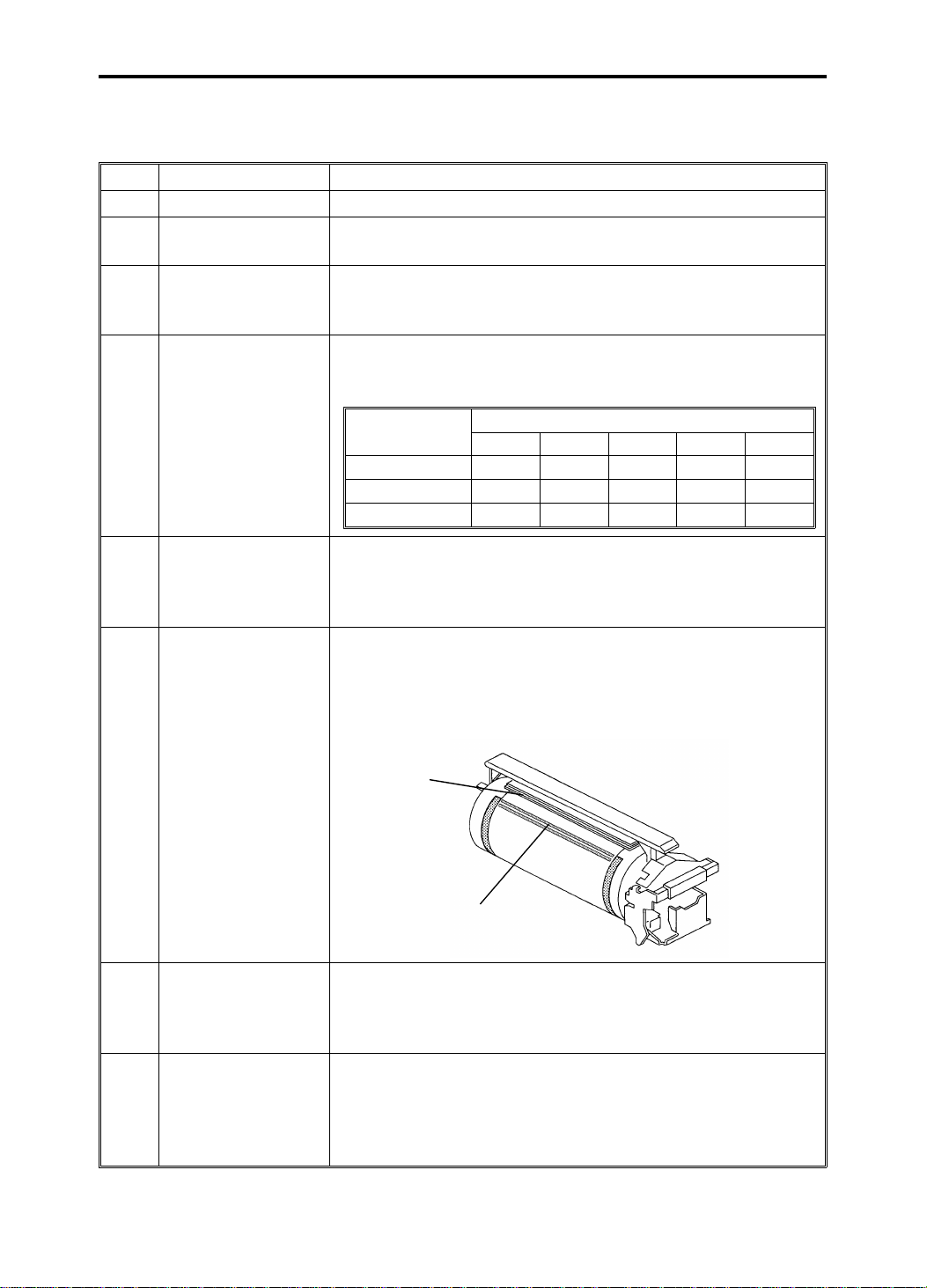
Drum Connector To ensure drum connection, a drum lock lever is added inside
5
Drum The rubber strip [A] has been added to the master clamper
the front door. To remove the drum from the machine, the
drum release lever must be pulled up to disconnect the drum
connector.
and the master stopper [B] (2 strips for C218, 1 strip for C219)
has been added to the surface of the drum.
This is to reduce master slipping when a high volume is
printed from the same master.
[A]
6
[B]
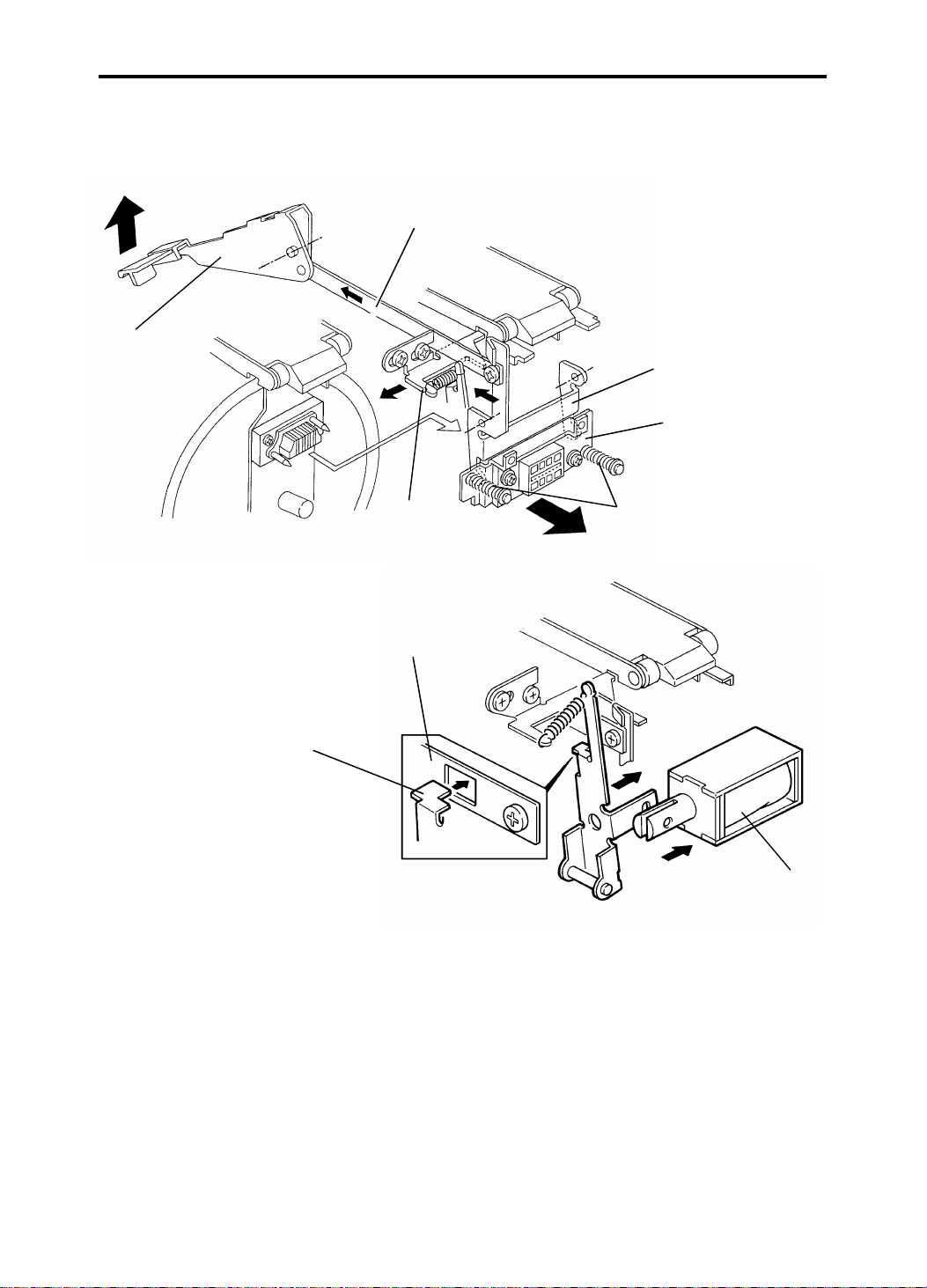
Ink Detection Board The location of the ink detection board has been changed
7
Paper Feed Table The paper table and the delivery table open/close detection is
8
from the upper side to the right side of the drum shaft. The ink
type switch which was not used (it was always set to the oil
type setting) has been removed.
done separately to enable paper table lowering regardless of
whether the delivery table is open or closed (C218 model).
Delivery table open/close detection is not available for the
C219 model.
1-4
Page 8
92
15 July 1994 DIFFERENCES BETWEEN THE #C210 MODEL AND #C218/C219 MODELS
SP Mode (Thermal
Paper Mode)
9
SP Mode (Sensor
Voltage)
10
Make-up Mode The image make-up mode has been made into an option. To
11
The following item is a difference only for the #C218 model.
Photo Mode The Photo Data Compensation Processor has been changed
12
The following items are differences only for the #C219 model.
Original Size
13
Detection
Paper Return
14
Mechanism
Paper Feed The paper feed pressure can be adjusted in three steps for
15
Wing Guide
16
(Delivery)
17 Air Knife Motor The number of air knife motors has been changed from 3 to 2.
Second Feed Roller The number of rollers on the second feed roller shafts has
18
Master Eject Roller The number of rollers on the master eject roller shafts has
19
To test the thermal head, SP Mode 92 has been added to
make a test print on the thermal paper without the master
clamp process.
SP-MODE
PROGRAM
SP modes 135 to 138 have been added to indicate the sensor
voltage on the operation display.
SP Mode No. 135: First Paper Exit Sensor
SP Mode No. 136: Second Paper Exit Sensor
SP Mode No. 137: Master Eject Sensor
SP Mode No. 138: Drum Master Detection Sensor
enable this mode, the IPU board must be replaced.
For the C218 model, up to 4 command sheets can be given
for an original.
For the C219 model, up to 2 command sheets can be given
for an original.
to improve image quality in the Photo mode.
The original size detection is eliminated for the C219 model.
The paper return mechanism has been eliminated for the
C219 model.
the C219 model.
The wing guide adjustment mechanism has been eliminated
for the C219 model.
been changed from 5 to 3.
been changed from 5 to 4.
Thermal Paper Mode
0: No 1: Yes 1
1-5
Page 9
GUIDE TO COMPONENTS 15 July 1994
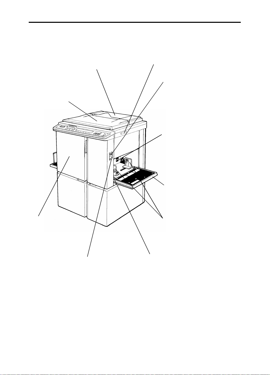
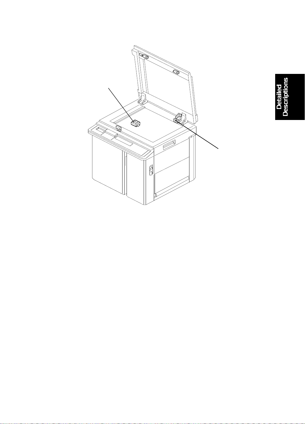
3. GUIDE TO COMPONENTS
Original Holder
A convenient place for
holding originals while
operating the mach ine.
Platen Cover
Lower this cover over
an original before
printing.
Original Table Release Lever
Use to open the original tab le
unit when installing the master.
Feed Roller Pressure
Lever
Use to adjust the contact
pressure of the paper fe ed
roller according to paper
thickness.
Separation Roller
Pressure Levers
Use to adjust the
separation roller
pressure to prevent
double feed.
Paper Feed Table
Set blank paper on this
table for printing.
Front Door
Open for access to
the inside of the
machine.
Paper Feed Table
Down Key
Press to lower the
paper feed table.
Paper Feed Side
Plates
Use to prevent paper
skew.
Side Plate Fine
Adjustment Dial
Use to shift the
paper feed table
sideways
1-6
Page 10
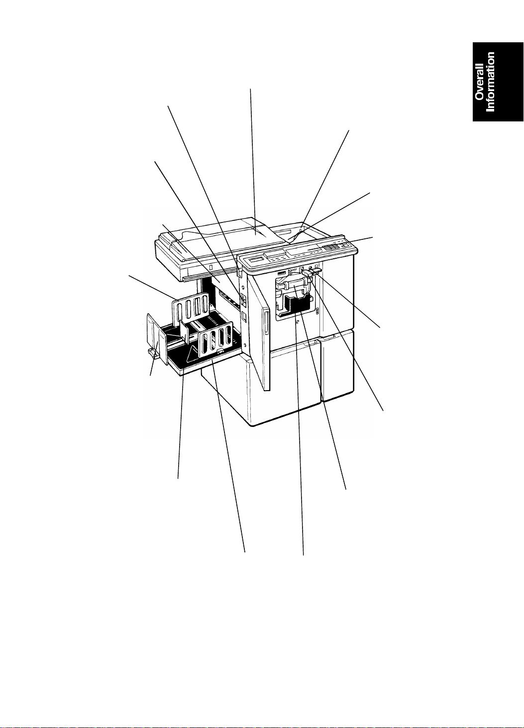
15 July 1994 GUIDE TO COMPONENTS
Master Eject Unit Open
Button
Press to remove misfed
paper or a misfed master.
Main Switch
Use to turn the
power on or off.
Master Eject
Container Cover
Open when removing
the master eject box.
Paper Deliver y
Side Plates
Use to align the
prints on the
paper delivery
table.
Paper Deliver y E nd
Plate
Use to align the
leading edge of prints
larger than A4, 81/2" x
11".
Small Size Paper Delivery
End Plate
Use to align the leading edge
of prints that are A4, 81/2" x
11" or smaller.
Original Table
Place the originals
on this table.
Master Cut Button
Press this button to cut
the master paper
leading ed ge after
installing a new master
roll.
Pressure Release
Lever
Use to install the
master roll.
Operation Panel
Operator controls
and indicators are
located here.
Drum Rotation
Button
Press to replace
the drum.
Drum Unit Lock
Lever
Lift to unlock and
pull out the drum
unit.
Drum Unit
The master is wrapped
around this unit.
Paper Deliver y Tabl e
Completed prints are
delivered here.
1-7
Ink Holder
Set the ink cartridge in
this holder.
Page 11
15
5
3
2
16
MECHANICAL COMPONENT LAYOUT 15 July 1994
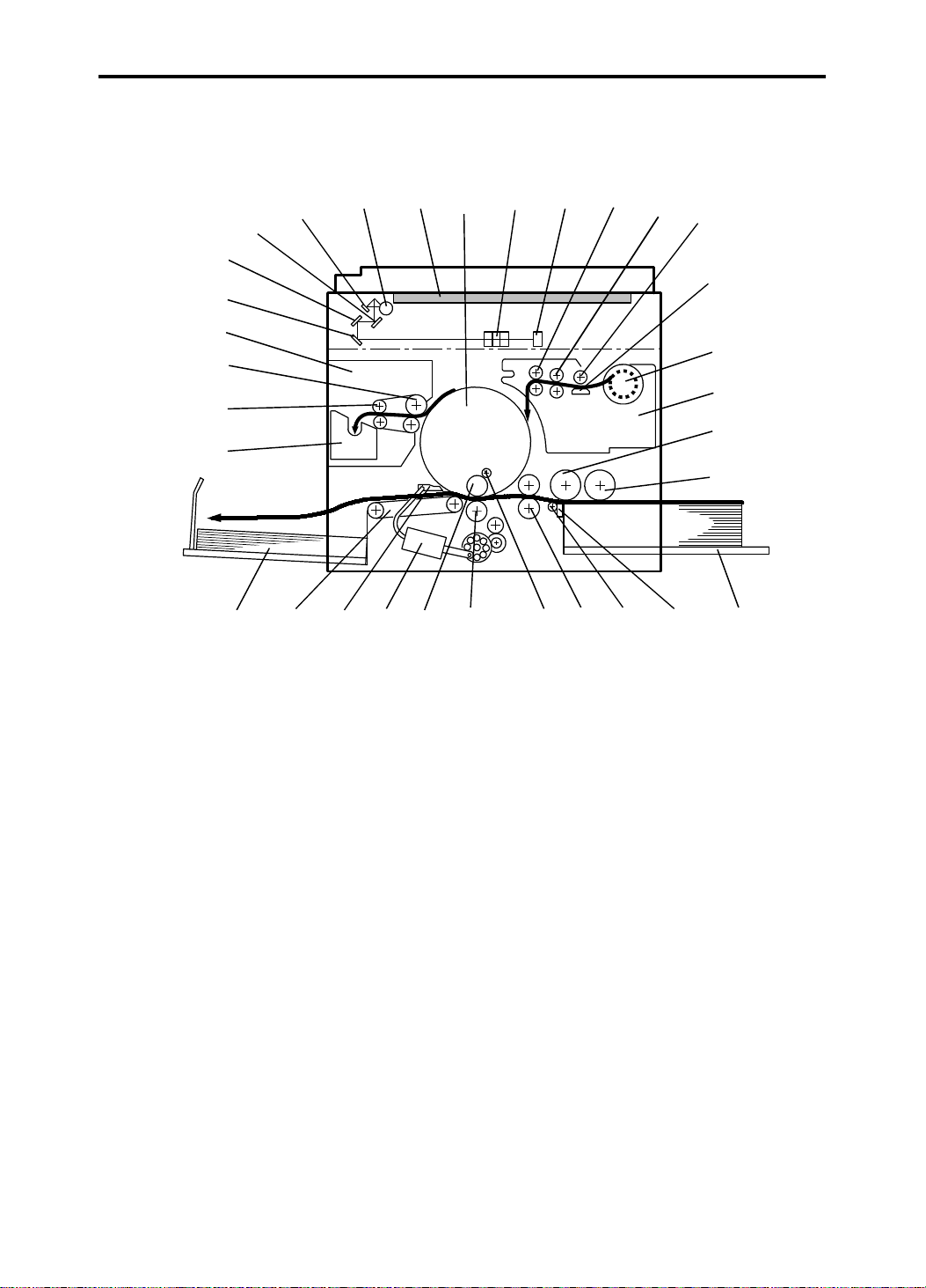
4. MECHANICAL COMPONENT LAYOUT
30
29
28
27
26
25
24
23
2122
1. Drum Unit
2. Lens
3. CCD
4. Reverse Roller
5. Master Feed Roller
6. Platen Roller
7. Thermal Head
8. Master Roll
9. Plotter Unit
10. Upper Separation Roller
11. Paper Feed Roller
12. Paper Table
13. Separation Plat e
14. Lower Separation Roller
15. 2nd Feed Roller
16. Doctor Roller
31
20
32
19
18
1
17
17. Press Roller
18. Ink Roller
19. Paper Exit Pawl Air Pump
20. Paper Exit Pawl
21. Transport Unit
22. Paper Delivery Table
23. Master Eject Box
24. 2nd Eject Roller
25. 1st Eject Roller
26. Master Eject Unit
27. 3rd Mirror
28. 2nd Mirror
29. 1st Mirror
30. Reflector
31. Fluorescent Lamp
32. Exposure Glass
4
14
13
6
7
8
9
10
11
12
1-8
Page 12

543
15 July 1994 ELECTRICAL COMPONENT LAYOUT
5. ELECTRICAL COMPONENT LAYOUT
1
9
2
8
7
6
1. Scanner Motor
2. Fluorescent Lamp Stab ilizer
3. CCD PCB
4. Platen Cover Position Sensor
6. Original Sensor
7. ADF Set Sensor
8. Scanner Home Position Sensor
9. Fluorescent Lamp
5. A/D Conversion PCB
COMPONENT DESCRIPTIONS
Index No. Name Function
1
4
Scanner Motor Drives the scanner (1st and 2nd).
Platen Cover
Position Sensor
Detects when the pla ten cover is
opened ab out 25° above the exposure
glass.
6
Original Sensor Detects if an original is placed on the
exposure glass.
7
ADF Set Sensor Detects when the optional document
feeder is closed.
8
Scanner Home
Position Sensor
Informs the CPU when the 1st scanner
is at the home position.
1-9
Page 13
2
DRIVE LAYOUT 15 July 1994
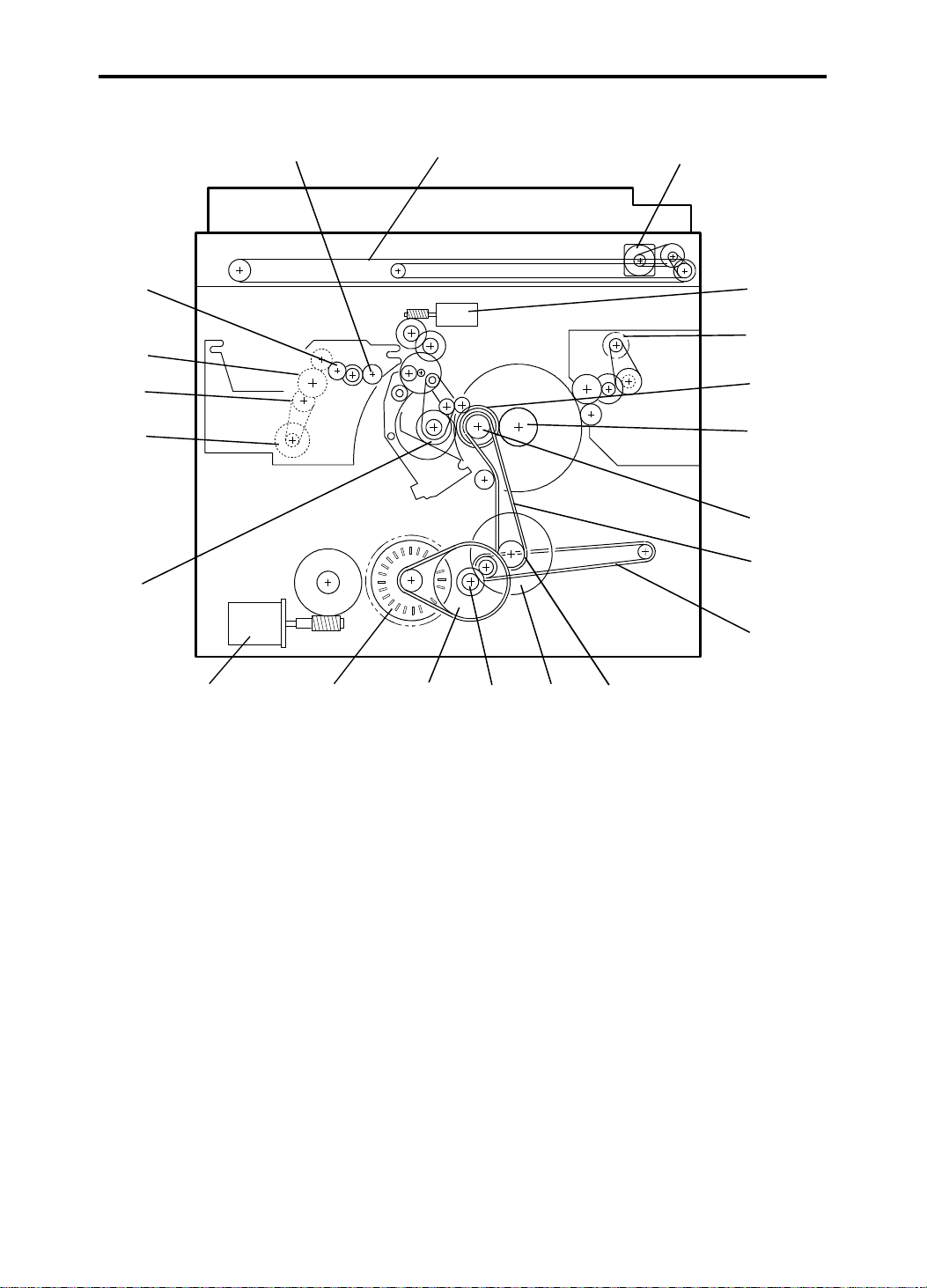
6. DRIVE LAYOUT
20
19
18
17
16
21
1
3
4
5
6
7
8
9
15
1. Scanner Belt
2. Scanner Motor
3. Image Position Motor
4. Master Eject Motor
5. Drum Drive Gear
6. Drum Unit Gear
7. Drum Drive Pulley
8. Main Drive Belt
9. Transport Belt
10. Printing Pressure Pulle y
11. Printing Pressure Gear
14
13 12
12. Idle Gear
13. Idle Pulley
14. Main Motor
15. Paper Table Drive Motor
16. Paper Feed Cam Gea r
17. Master Feed Motor
18. Timing Belt
19. Platen Roller Gear
20. Master Transport Roller Gear
21. Reverse Roller Gear
11
10
1-10
Page 14

SECTION 2
DETAILED SECTION
DESCRIPTIONS
Page 15
15 July 1994 MASTER EJECT
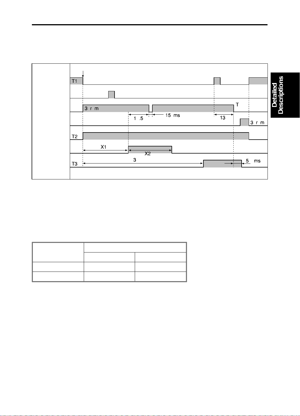
1. MASTER EJECT
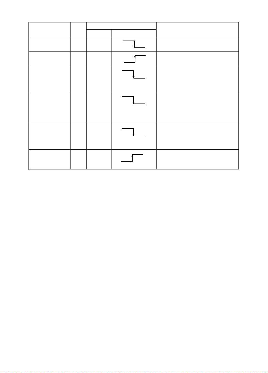
1.1 ELECTRICAL TIMING: #C21 8 MODELS
First Drum
Position Senso r
Second Drum
Position Senso r
Main Motor
Reversing
Main Motor
Advancing
Master Eject
Motor
Master Eject
Solenoid
Master Eject
Clamper
Solenoid
The drum stops its reverse rotation for 150 ms when the tra iling edge of the
master is about 5 millimeters away from th e mast er eject rollers to ensure
that the master eject process is successf ul (only for #C218 models).
Drum Type
#C218 Models
A3/DLT A4/LT
X1 (degrees) 70 174
X2 (degrees) 39 55
2-1
Page 16
MASTER EJECT 15 July 1994
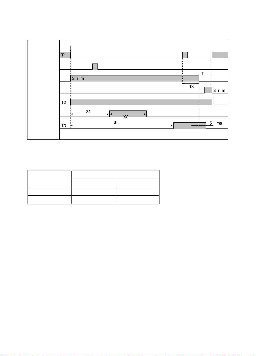
1.2 ELECTRICAL TIMING: #C21 9 MODELS
First Drum
Position Senso r
Second Drum
Position Senso r
Main Motor
Reversing
Main Motor
Advancing
Master Eject
Motor
Master Eject
Solenoid
Master Eject
Clamper
Solenoid
Drum Type
#C219 Models
B4 LG
X1 (degrees) 85 85
X2 (degrees) 55 55
2-2
Page 17
[D]
15 July 1994 SCANNER
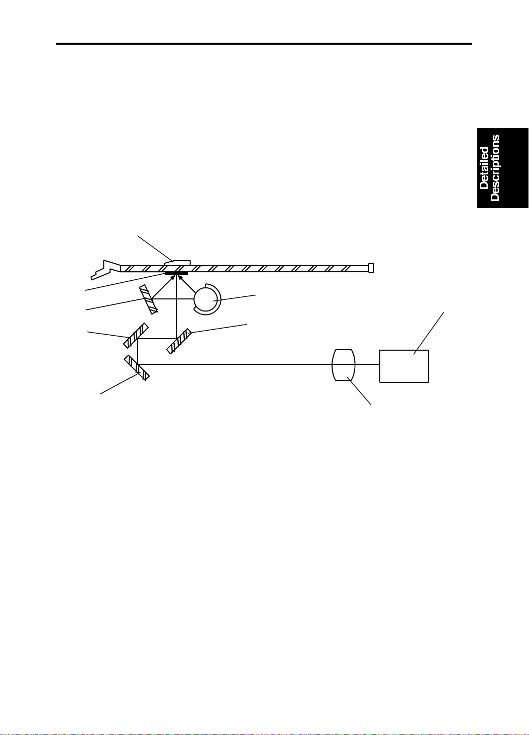
2. SCANNER
2.1 OVERALL
A book type scanner is used for the #C218/#C219 mod els. There are 2
modes for scanning origina ls.
Platen Cover Mode: The original is placed on the exposu re glass, and the
scanner motor drives the scanner to scan the original.
ADF Mode: When an optional Docu men t Fee de r is installed, the original is
fed onto the exposure gla ss. The scann er move s 24 mm away from the CCD
and remains still as it scans the original. The scanner comes back to the
home position when the scanning is finished.
[H]
[G]
[F]
[E]
The light from the fluoresce nt lamp [A ] is re fle cte d fro m t he origin al, by the
first [B], second [F], and th ird [E ] mirrors an d goes th rou gh the lens [D] into
the CCD [C].
[I]
[A]
[C]
[B]
[G]: Reflector
In the Platen Cover Mo de , th e CCD re ad s the white plate [H] on the back of
the original scale [I] each time be fo re scanning to obtain a standa rd white
level. The standard white data are used to corre ct dist ortion. The scanner is
at its home position when it rea ds th e white level.
In the ADF mode, as the scanner move s 24 mm, th e CCD read s the wh ite
plate installed on the ADF.
2-3
Page 18
SCANNER 15 July 1994
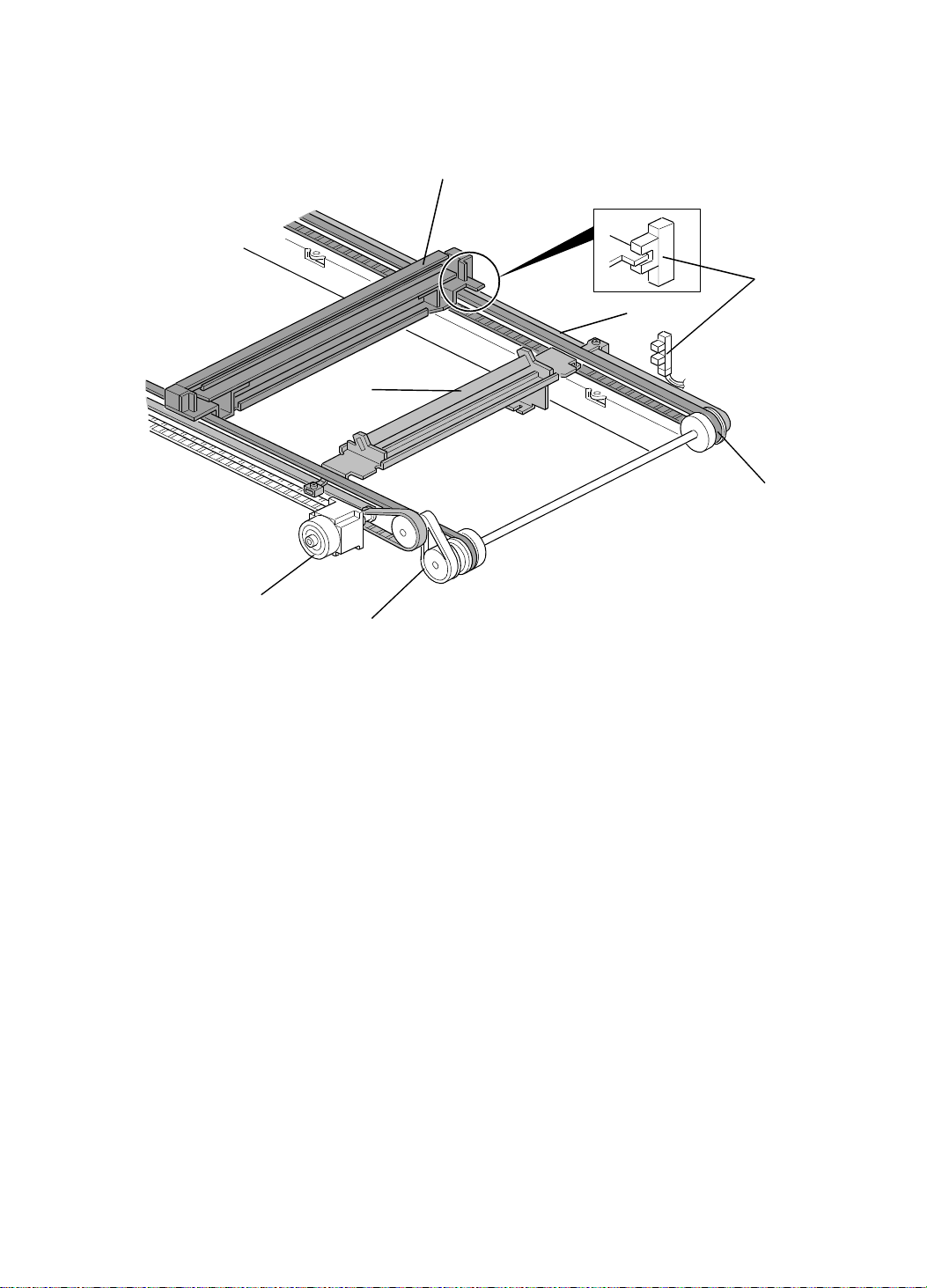
2.2 SCANNER MECHANISM
[B]
[Front Side]
[E]
[D]
[C]
[F]
[Rear Side]
[A]
[G]
A stepper motor is used fo r the scann er motor [A] to drive the scanners. The
first scanner [B], which consist s of th e exp osu re lamp and the first mirror, is
driven by the first scanner belt [F]. The seco nd scann er [C] , which consists of
the second and the th ird mirror, is driven by the second scanner belt [D] . Bo th
scanners move along the gu ide rails.
The timing belt [G] moves t he secon d scanner at half the velocity of the first
scanner. This is to maintain the focal distance between th e orig inal and the
lens during scanning.
The scanner home position is detected by the home positio n sensor [E]. In
the Platen Cover Mode, the scanner scans the original on the exposure glass
for the full A3 lengt h, then returns until the scann er ho me po sitio n sensor is
activated. In the ADF Mod e, the scanner moves 24 mm backwards (away
from the CCD), to scan the original which is fed by the ADF. When the
master making process is finishe d and the ADF motor stops, the scanner
goes back to the home position.
2-4
Page 19
15 July 1994 SCANNER
2.3 PLATEN COVER POSITI ON DETECTION
[B]
[A]
When the platen cover is opene d ab ou t 25 deg rees, the Platen Cover
Position Sensor [A] is deactiva ted. When this sensor is deactivate d, the
Original Sensor [B] is able to det ect the origin al on the expo sure glass.
When the Platen Cover Position Sensor is deactivat ed and the Origin al
Sensor detects no original on the expo sure glass, the machin e indicates
"SET THE ORIGINALS" on the operat ion displa y. This is t o pre ven t wast ing
of the master that wo uld occur whe n the Master Making key is pressed with
no original placed on the exposure glass.
When the original is placed on the expo sure glass and the Master Making
key is pressed with the pla te n cover opened more than 25 degrees (a s the
Platen Cover Position Senso r is deact ivat ed ), th e shadow erase function is
enabled.
2-5
Page 20
SCANNER 15 July 1994
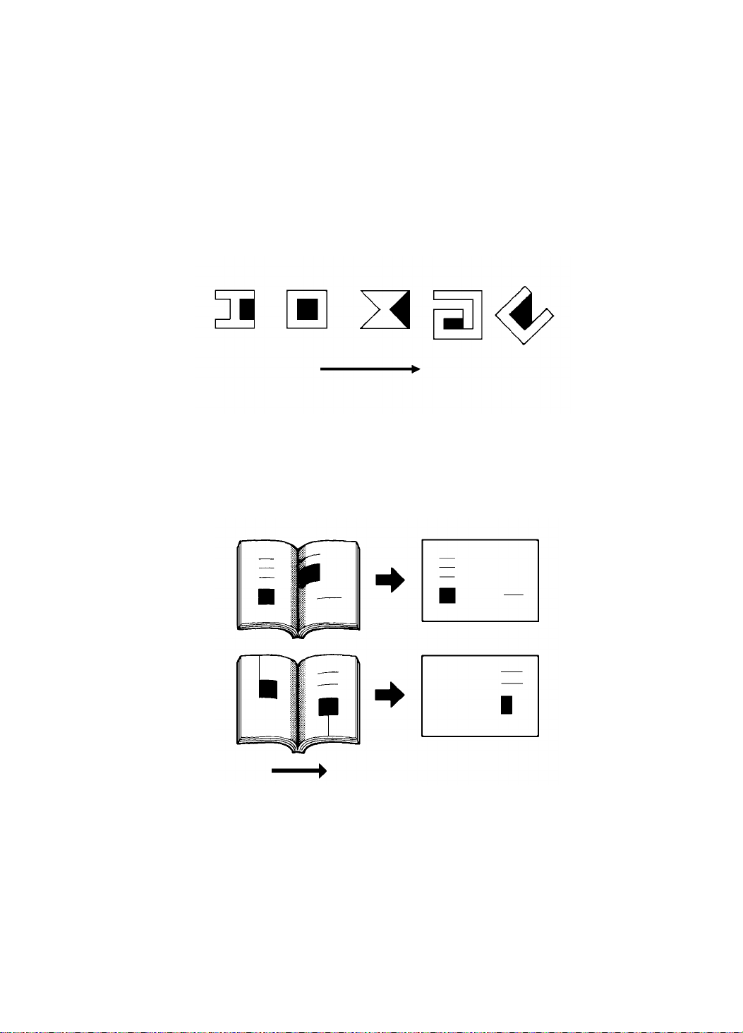
Notes regarding the shadow erase function:
• Margins of 1 mm, 0.02" on all four sides of the original will be erased. The
width of the margins will change depending on the rep rod uction ratios.
• Shadows near the book edge might not be erased complet ely.
• If the shape of the originals are as sho wn be low, shadows might appear
on the prints. In this case, make the master with the platen cover clo sed .
Shadow
Scanning directio n
• If a line or solid image is on the margin at the center and at the edges
being erased, the image might be erased as shown below.
Scanning directio n
2-6
Page 21
Scanner HP
15 July 1994 SCANNER
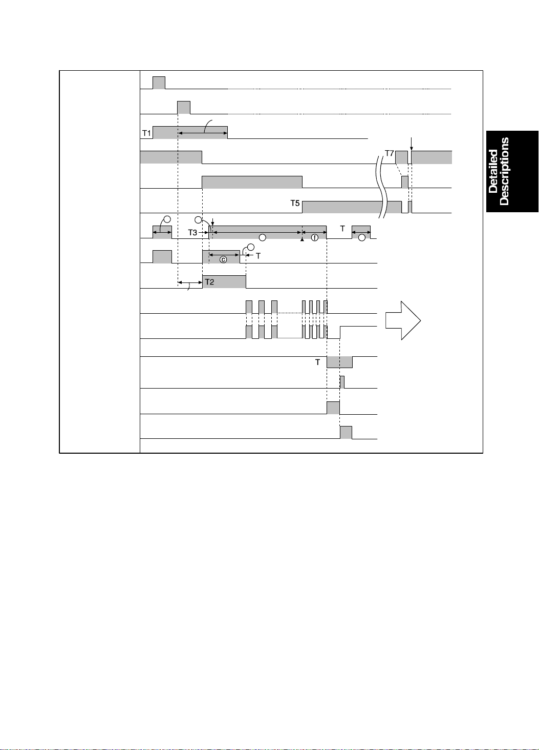
2.4 ELECTRICAL TIMING
First Drum
Position Sensor
Second Drum
Position Sensor
Main Motor
Reversing
Scanner Home
Position
Scanner Motor
Scanner Motor
Reversing
Master Feed
Motor
Reverse Roller
Clutch
Master Feed
Clamper Solenoid
160° of Drum Rotation
Buckle Sen sor
Main Motor
Advancing
Left Cutter
Switch
Right Cutter
Switch
218.5° of Drum Rotation
Plotting Start
Plotting Max.
To Trial Print
Cutter Motor
Cutter Motor
Reversing
For C218 model a: 21.5 mm b: 0.9 mm For C219 model a: 18.5 mm b: 1.0 mm
e: 412 mm f: 60 mm e: 359 mm f: 61 mm
g: 40 mm c: 38 mm g: 40 mm c: 41 mm
d: 5 mm d: 5 mm
T1: After the master eject process is completed, the main moto r st art s
reverse rotation at 30 rpm. At th e same time, the master feed motor and
the reverse roller magnetic clutch tu rn on to feed the ma ste r 21. 5
millimeters (18.5 mm for the C219 model).
T2: The master feed clamp er sole no id is e ne rgize d when the drum rotates
160 degrees past the second drum position sensor (162 degrees for the
C219 model). At the same time, th e reve rse roller magnetic clutch is
turned on and th e scanner motor starts t o rot ate.
2-7
Page 22

SCANNER 15 July 1994
T3: When the scanner has move d 20 millimeters from its home position (17
mm for the C219 model), the master starts to be fed. When the maste r
has been fed 0.9 millimeters (1.0 mm for the C219 model), the thermal
head starts plotting on the mast er.
The leading edge is zero when the sca nner is 12 millimet ers from its
home position. The leading edge margin can be adjusted within the rang e
of 4 to 10 millimeters by SP mode No.33.
T4: When the master has been fed 38 millimeters (41 mm for C219 models),
the reverse roller magnetic clutch tu rns of f. Then the master is fed 5
millimeters more and the master feed clamper solenoid is de-energized to
close the master clamper. The master is fed in the same way as in #C210
models. The original transp ort and the maste r f eed mot ors speed up once
the master plotting is done. The master feeding lengths for plotting are:
For #C218 models
412 millimeters: A3/DLT dru m
204 millimeters: A4/LT dru m
For #C219 models
355 millimeters: for both B4 and LG drums
T5: When the scanner has scanned the fu ll scanning length (the sa me len gth
as the master feeding length), the scanner motor starts its reve rse
rotation to bring back th e scanner to the home position.
T6: The master feed mot or stops when the master has been fe d 53 4.4
millimeters (479.5 mm for the C219 model). At the same time, the cut te r
motor starts rota tin g to cut the master. The cutter motor changes its
rotation direction when th e cut ter h old er pu she s the right cutt er switch.
The cutter motor st ops wh en the cutt er ho lder goes back to the home
position to activate the left cutter switch (the same wa y as in #C210
models).
When the right cutter switch is activated, the drum starts rotatin g to go
back to its home position . Whe n the left cutter switch is activa te d (when
the cutter comes back to it s home position), the master fe ed motor turns
on again to feed the master 40 millimeters.
T7: When the scanner moto r st ops it s reverse ro ta tio n, the scanner motor
rotates forward until th e scanner home position sensor is activat ed .
2-8
Page 23
[D]
[E]
15 July 1994 SCANNER
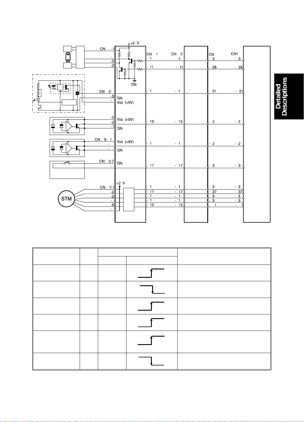
2.5 CIRCUIT
[A]
[B]
[C]
AD Conversion PCB
Image Processing PCB Main PCB
Scanner Motor
Component
Name
Fluorescent
Lamp [A]
Fluorescent
Lamp [A]
Original Sensor
[B]
Scanner HP
Sensor [C]
Platen Cover
Position Sensor
[D]
ADF Set Sensor
[E]
I/O
A/D Conversion PCB
CN No. Signal Level
Out 601-b10
Out 608-3
In 602-4
In 602-2
In 605-B9
In 602-8
0V
24V
0V
0V
0V
5V
Description
5V
Signal goes high when the lamp on
signal turns on.
Signal goes low when the lamp on
signal turns on.
0V
5V
Signal goes high when the sensor
detects an original.
5V
Signal goes high when the sensor
detects an original.
Signal goes high when the sensor
5V
detects an original.
Signal goes low when the lead
switch is turned on.
0V
2-9
Page 24
[E]
DRUM 15 July 1994
3. DRUM
3.1 DRUM CONNECTION MECHANISM
[D]
[A]
[C]
[B]
[F]
[D]
[H]
[G]
When the drum release lever [A] in fro nt of th e mach ine is raised, the
connector [B] is push ed away fro m t he drum by th e bra cket [C] through the
link [D], and is disconnected. The bracke t [C] also pu she s the drum lock leve r
[F] to release the dru m lock allowing the drum to be removed. Wh ile th e drum
is away from its home position, the drum lock solenoid [G] is energized and
the stopper [H] locks the link [D] to preven t th e dru m from be ing pulle d out.
The solenoid is de-energized when the drum stops at th e ho me po sitio n
(when the 1st drum position senso r is act uated).
2-10
Page 25

15 July 1994 DRUM
3.2 CIRCUIT FOR #C218 MODE LS
Main PCB
[A]
(Drum Unit Connector)
[B]
Common
[C]
Common
[D]
LED Drive
Component
Name
Drum Detection
Switch [A]
I/O
CN No. Signal Level
In 105-26
Drum Rotation
LED (Red) [B] Out 105-18
Drum Rotation
LED (Green) [B] Out 105-19
Drum Rotation
Button (N.C.) [C]
Drum Rotation
Button (N.O.) [C]
In 105-21
In 105-22
Drum Master
Detection
In TP102
Sensor [D]
Ink Supply
Solenoid [E]
Out 104-17
Main PCB
24V
0V
0V
24V
0V
0V
24V
[F]
(Drum Unit
Frame)
Ink Detection PCB
Description
Signal goes Low when the drum
0V
unit is slid out.
Signal goes High when the drum is
2.8V
not in the home position. (The LED
lights red.)
Signal goes High when the drum is
2.8V
in the home position. (The LED
lights green.)
Signal goes Low when the button
is pressed.
0V
24V
Signal goes High when the main
switch is turned on.
The voltage between TP102 and
2.5V
ground becomes more than 2 volts
when a master is on the drum.
Signal goes Low when the
solenoid is energized.
0V
[E]
Ink
Detecting Pin
[G]
Ink Roller
Doctor Roller
2-11
Page 26
DRUM 15 July 1994
Component
Name
Drum Lock
Solenoid [F]
Ink Detection [G]
I/O
Out 104-18
In
Color Drum
Detection [H]
In 104-14
Drum Size
Detection [H]
In 104-15
A4/LT Drum
Detection [H]
In 104-16
Drum Unit
Safety Switch Out
Main PCB
CN No. Signal Level
24V
104-20
(TP105)
-12V
5V
5V
5V
118-7
(Drum
Unit)
0V
Description
Signal goes Low when the
solenoid is energized.
0V
0V
Signal goes High when there is no
ink.
Signal goes Low when the color
drum is installed. (CN118-2 and -3
0V
are shorted.) The Color Drum
indicator will light.
Signal goes Low when the drum is
installed. (CN118-2 and -4 are
0V
shorted.) The A3 or DLT Drum
indicator will light when CN118-2
and -5 are open.
Signal goes Low when the A4/LT
drum is installed. (CN118-2 and -5
0V
are shorted.) The A4 or LT Drum
indicator will light.
CN118-7 of the drum unit
24V
connector becomes 24 volts when
the drum unit is set.
2-12
Page 27

15 July 1994 DRUM
3.3 CIRCUIT FOR #C219 MODE LS
[A]
[B]
[C]
[D]
Main PCB
(Drum Unit Connector)
[E]
Common
[F]
Common
LED Drive
(Drum Unit
Frame)
Ink Detection PCB
Ink
Detecting Pin
[G]
Ink Roller
Doctor Roller
Component
Name
Drum Detection
Switch [A]
I/O
CN No. Signal Level
In 105-4
Drum Rotation
LED (Red) [B] Out 105-18
Drum Rotation
LED (Green) [B] Out 105-19
Drum Rotation
Button (N.C.) [C]
Drum Rotation
Button (N.O.) [C]
In 105-8
In 105-7
Drum Master
Detection
In TP102
Sensor [D]
Ink Supply
Solenoid [E]
Drum Lock
Solenoid [F]
Out 104-16
Out 103-19
Main PCB
24V
0V
0V
24V
0V
0V
24V
24V
Description
Signal goes Low when the drum
unit is slid out.
0V
Signal goes High when the drum is
2.8V
not in the home position. (The LED
lights red.)
Signal goes High when the drum is
2.8V
in the home position. (The LED
lights green.)
Signal goes Low when the button
0V
is pressed.
24V
Signal goes High when the main
switch is turned on.
The voltage between TP102 and
2.5V
ground becomes more than 2 volts
when a master is on the drum.
Signal goes Low when the
solenoid is energized.
0V
Signal goes Low when the
solenoid is energized.
0V
2-13
Page 28

DRUM 15 July 1994
Component
Name
Ink Detection [G]
I/O
In
Color Drum
Detection [H]
In 104-18
Drum Unit
Safety Switch Out
Main PCB
CN No. Signal Level
104-20
(TP105)
0V
5V
118-7
(Drum
Unit)
0V
Description
Signal goes Low when there is no
-12V
ink.
Signal goes Low when the color
drum is installed. (CN118-5 and -6
0V
are shorted.) The Color Drum
indicator will light.
CN118-7 of the drum unit
24V
connector becomes 24 volts when
the drum unit is set.
2-14
Page 29
Counter "0"
15 July 1994 DELIVERY
4. DELIVERY
4.1 ELECTRICAL TIMING
1st Drum Position Sensor
2nd Drum Position Sensor
Cutter Motor
Cutter Motor ON Print Key ON
Stop Key
ON
T2
Vacuum Fan Motor
Air Knife Motors
Paper Feed Solenoid
Printing Pressure Sensor
Main Motor
Paper Table Height Sensor
Paper Table Drive Motor
T1
T1: The cutter motor, vacuum fan motor, and air knife motors turn on.
The main motor turns o n whe n th e cutter motor stops rotating.
T2: The vacuum fan motor and the air knife motors turn off when the printing
• The on/off timing for the vacuum fan motor, air knife motors a nd the main
pressure sensor is deactivated and the 1st drum positio n sensor is
activated.
motor is different from the #210 model.
2-15
Page 30
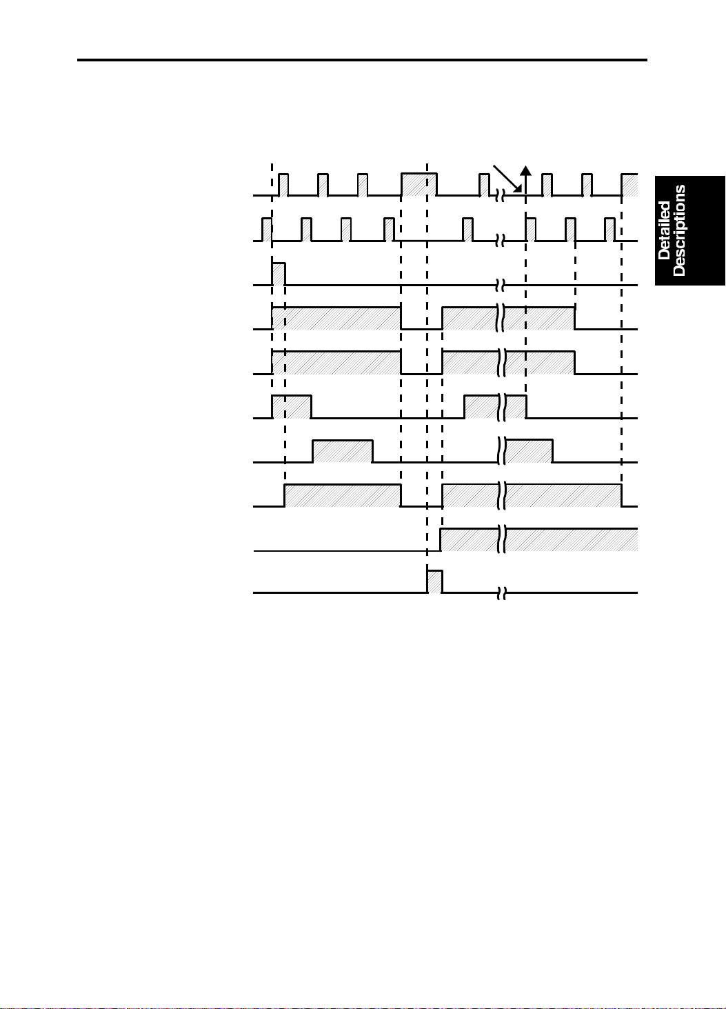
DELIVERY 15 July 1994
4.2 CIRCUIT FOR #C218 MODE LS
[A]
[B]
A
K
C
E
A
K
C
E
CN101-2
CN102-7
CN102-12
-1
-4
-3
-6
-5
-8
-7
+5V
+5V
+5V
+5V
GND
24V
FU101
2A
CN103
-9
-22
-13
-18
-14
-17
-15
-16
[D]
M
[E]
M
[F]
M
[G]
M
Paper Table
CN102-26
GND
-25
[C] Delivery Table
Main PCB
Component
Name
1st Paper Exit
Sensor [A]
2nd Paper Exit
Sensor [B]
Delivery Table
Open Switch [C]
Vacuum Fan
Motor [D]
Air Knife Motor
[E]
Air Knife Motor
[F]
Air Knife Motor
[G]
I/O
CN No. Signal Level
In TP101
In TP103
In 102-25
Out 103-9
Out 103-13
Out 103-14
Out 103-15
Main PCB
0V
0V
7.5V
0V
26V
26V
26V
26V
5 msec
Description
3V
Signal goes High when the paper
is on the sensor.
3V
Signal goes High when the paper
is on the sensor.
Pulse signal goes to Low when the
delivery table is opened.
Signal goes Low when the motor is
energized.
0V
Signal goes Low when the motor is
energized.
0V
Signal goes Low when the motor is
energized.
0V
Signal goes Low when the motor is
0V
energized.
The paper table and the delivery table open/ close detection is done
separately to enable paper table lowerin g reg ard less of whethe r the delive ry
table is open or closed.
2-16
Page 31

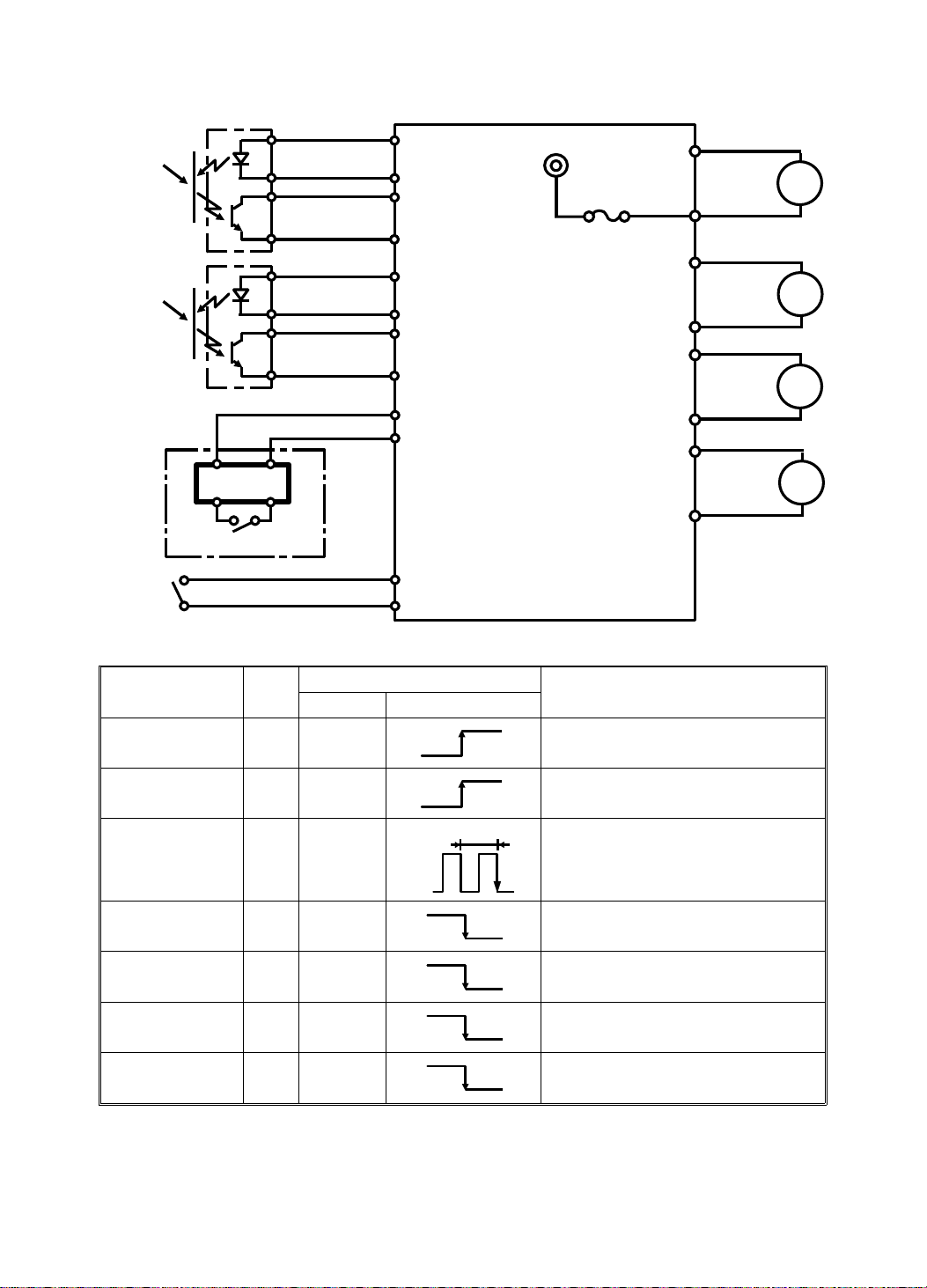
15 July 1994 DELIVERY
4.3 CIRCUIT FOR #C219 MODE LS
CN103
-8
-7
-14
-13
-12
-11
[D]
M
[E]
M
[F]
M
[A]
[B]
A
K
C
E
A
K
C
E
CN101-2
CN105-22
-23
-1
-4
-3
-6
-5
-8
-7
+5V
+5V
+5V
+5V
GND
24V
FU101
2A
[C] Paper Table
Main PCB
Component
Name
1st Paper Exit
Sensor [A]
2nd Paper Exit
Sensor [B]
Paper Table
Open Switch [C]
Vacuum Fan
Motor [D]
Air Knife Motor
[E]
Air Knife Motor
[F]
I/O
CN No. Signal Level
In TP101
In TP103
In 105-22
Out 103-8
Out 103-12
Out 103-14
Main PCB
0V
0V
7.5V
0V
26V
26V
26V
5 msec
Description
3V
Signal goes High when the paper
is on the sensor.
3V
Signal goes High when the paper
is on the sensor.
Pulse signal goes to Low when the
paper table is opened.
Signal goes Low when the motor is
energized.
0V
Signal goes Low when the motor is
energized.
0V
Signal goes Low when the motor is
energized.
0V
Delivery table open/close detection is not available for the #219 model.
2-17
Page 32
CHANGES ONLY FOR C219 MODELS 15 July 1994
5. CHANGES ONLY FOR C219 MODELS
The following items have been chang ed only for the #C21 9 mod el.
5.1 PAPER FEED
• The paper return mechanism has been eliminated.
• The Feed Roller pressure can be adjusted in 3 steps.
• The feed pressure lever on the feed roller asse mbly has bee n elimin at ed .
• The rubber material for the Paper Feed Roller and the Separation Roller
has been changed to improve longevity, and ensu re stable friction.
• The Paper Feed Roller shaft has been changed to a light-weight material.
Therefore, the torque limiter in the Paper Fee d Rolle r, which was there to
prevent the roller from over-runnin g, has been elimina te d.
• The number of rollers on the second feed roller shaf ts ha s been cha ng ed
from 5 to 3.
2-18
Page 33
15 July 1994 CHANGES ONLY FOR C219 MODELS
5.2 DELIVERY
• The number of transport belts has been changed from 3 to 2.
• The wing guide has been eliminated for the #C219 model.
2-19
Page 34

SECTION 3
INSTALLATION
Page 35
15 July 1994 INSTALLATION PROCEDURE
1. INSTALLATION PROCEDURE
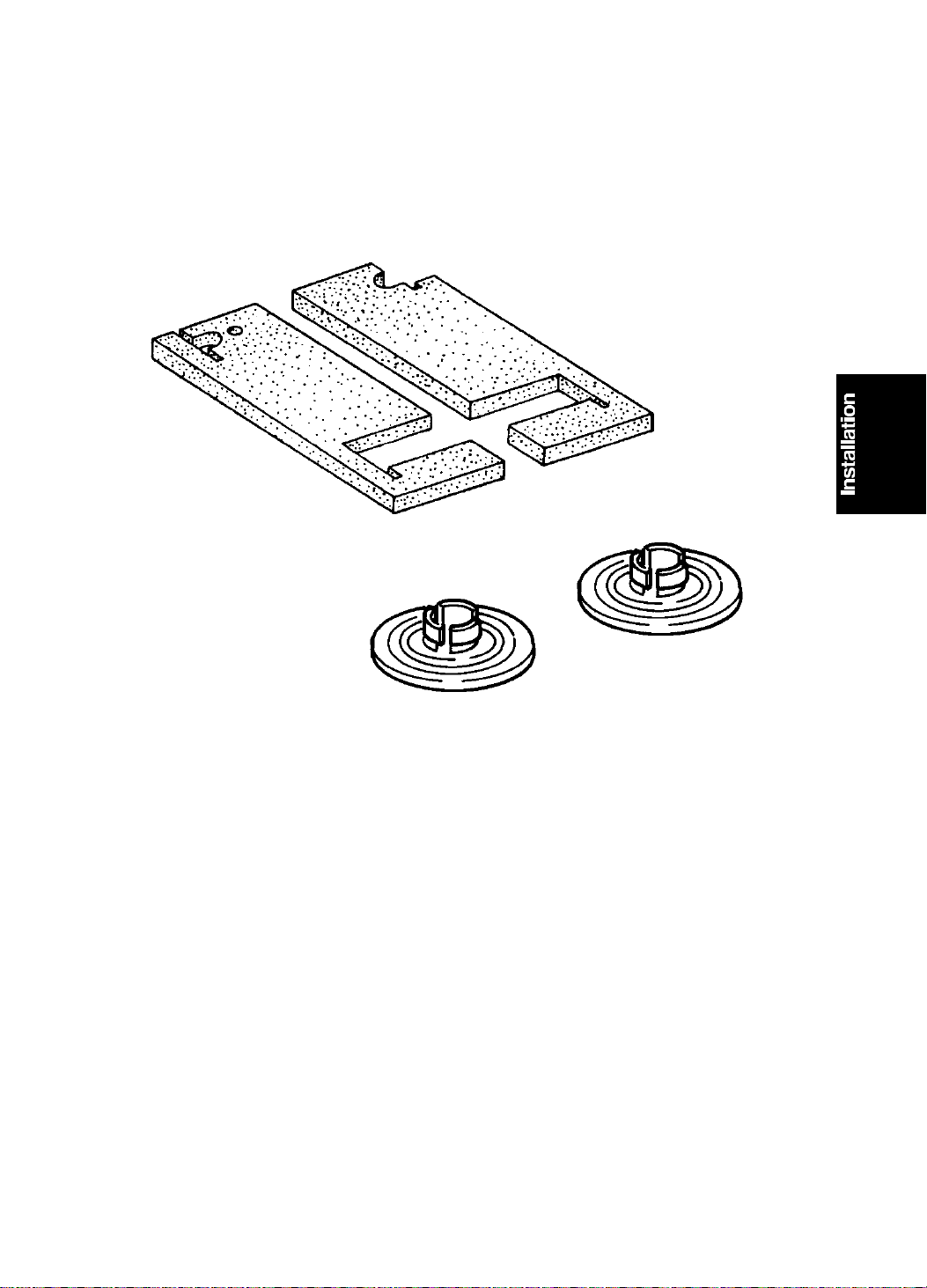
1.1 ACCESSORY CHECK
Make sure that you have all the accesso ries liste d below.
[A]
(Only for the C218 mode l)
[B]
A. Base Pad (Only for the C218 model)................................................2
B. Master Spool......... .. .................... .. .............................. .. ....................2
Operating Instructions
3-1
Page 36
[A]
[D]
INSTALLATION PROCEDURE 15 July 1994
2. INSTALLATION PROCEDURE
MAIN BODY
[A]
[A]
CAUTION: Do not hold the scanner unit when pushing the machine or
the scanner unit safety switch may be dam age d .
1. Place the machine on the table.
NOTE: The screw holes in th e bo ttom plate of the machine must line up
with the screw holes in the table.
2. Remove the strips of tape [A ] securing the covers and units shown ab ove .
[B]
[C]
3. Open the front door and slide out the drum unit [B].
4. Open the master clamper an d remo ve the clamp [C].
5. Open the paper feed ta ble and remove the cardboard cove r [ D] pro te cting
the paper feed roller.
3-2
Page 37

[F]
15 July 1994 INSTALLATION PROCEDURE
[G]
[H]
[E]
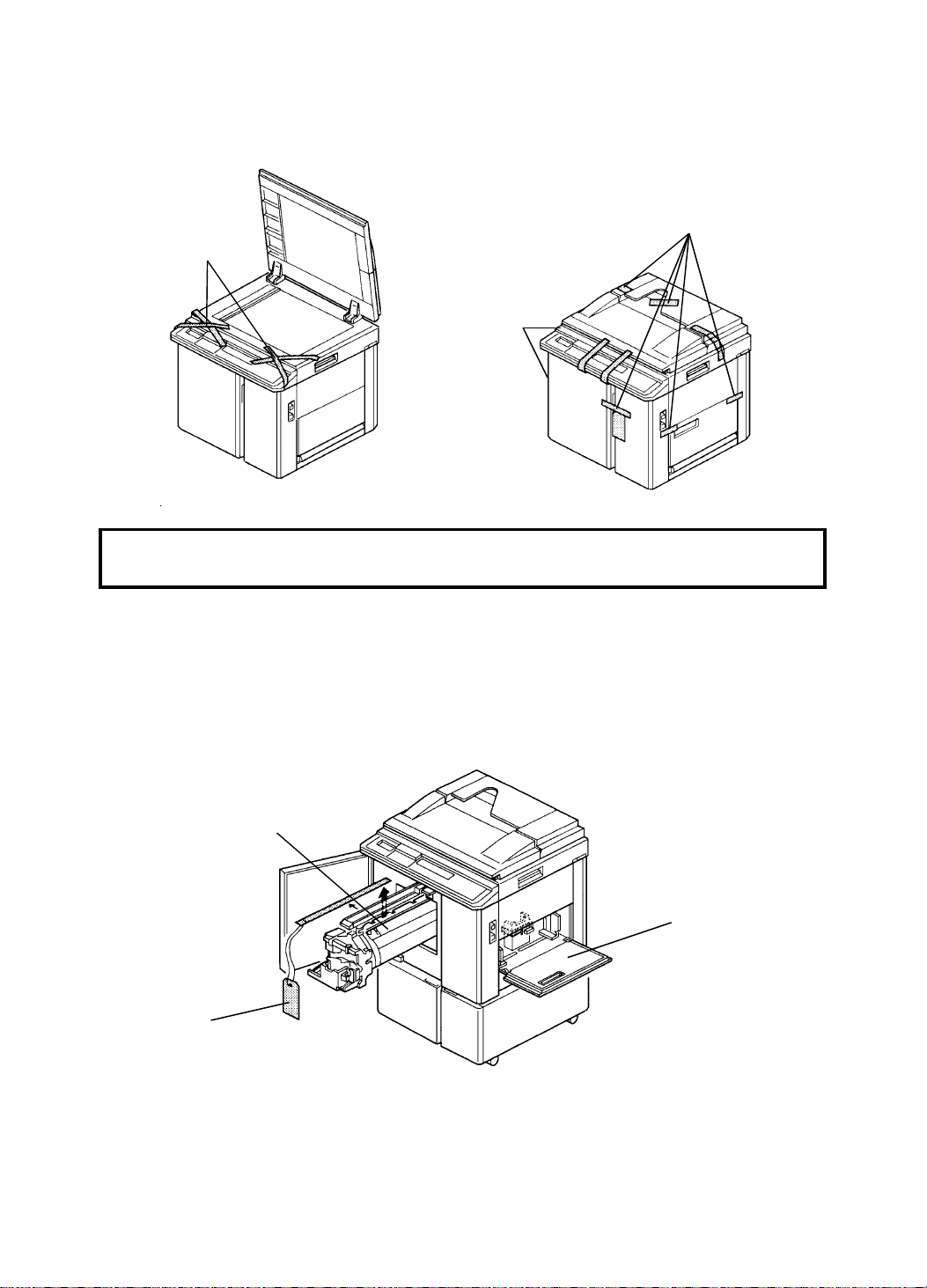
6. Open the paper delivery table and remove th e strip of tape [E] prot ect ing
the end fence .
7. Remove the cardboard [F] under the scanner unit.
8. Open the scanner unit and chan ge the posit ion of screws [G ] from
transport position to opera ting position.
9. Open the doors (2 strips of tape [H]) of the option al ta ble and take out the
plastic bag containing 2 screws.
3-3
Page 38
INSTALLATION PROCEDURE 15 July 1994
[B]
[A]
[C]
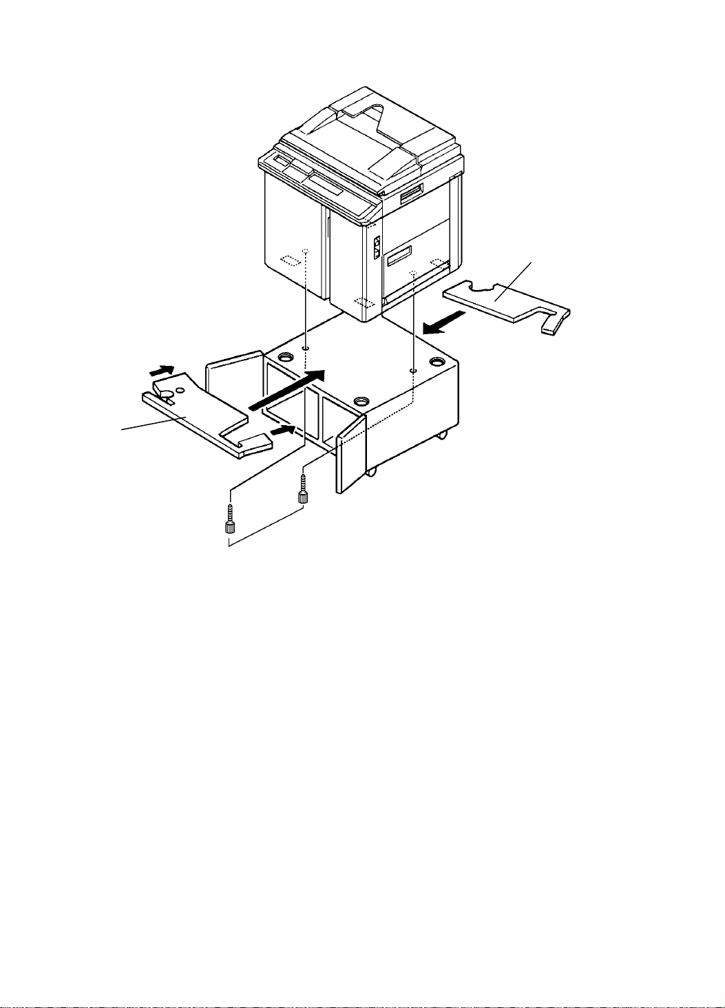
10. Raise the front sid e of t he machine and position the base pa d [A] under
the machine. Then raise the rear side of the machine and position the
other base pad [B] under the machine. (This procedure is necessa ry o nly
for the C218 model.)
11. Secure the machine to the table with the two scre ws [C] pa cked wit h th e
table.
NOTE: Make sure the ma chin e legs fit through the cutouts in the base
pads.
3-4
Page 39

15 July 1994 INSTALLATION PROCEDURE
12. Open the paper feed table [A]
and neatly stack the printing
paper on the ta ble.
13. Slide the paper feed side plates
[B] gently u p against the pa per
[A]
stack.
[B]
14. Open the paper delivery table
[C] and adjust the position of
the end plate [D] an d th e side
plates [E] according to the
printing paper size. Refer to the
paper size scale on the table.
15. Install the ink cartridg e [F] .
a. Open the front door and
lower the ink holder [G].
b. Remove the ink cartridge
cap.
c. Insert the ink cartridge in the
ink holder and raise the ink
holder to the origina l posit ion.
d. Close the front door.
[E]
[D]
[C]
[F]
[G]
3-5
Page 40
[A]
INSTALLATION PROCEDURE 15 July 1994
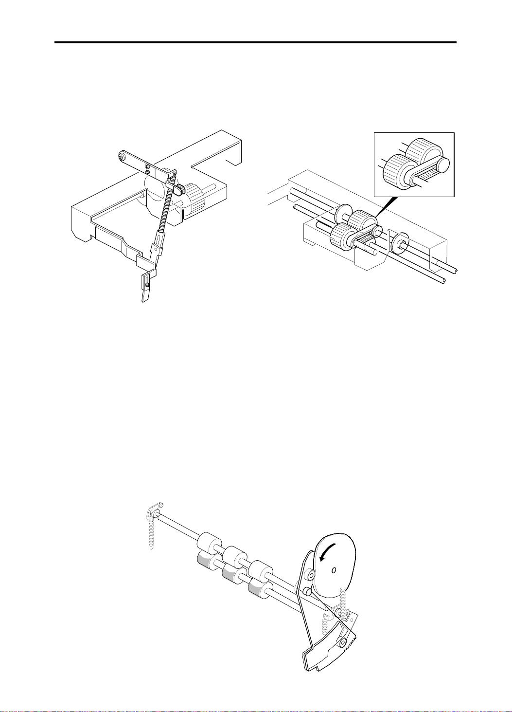
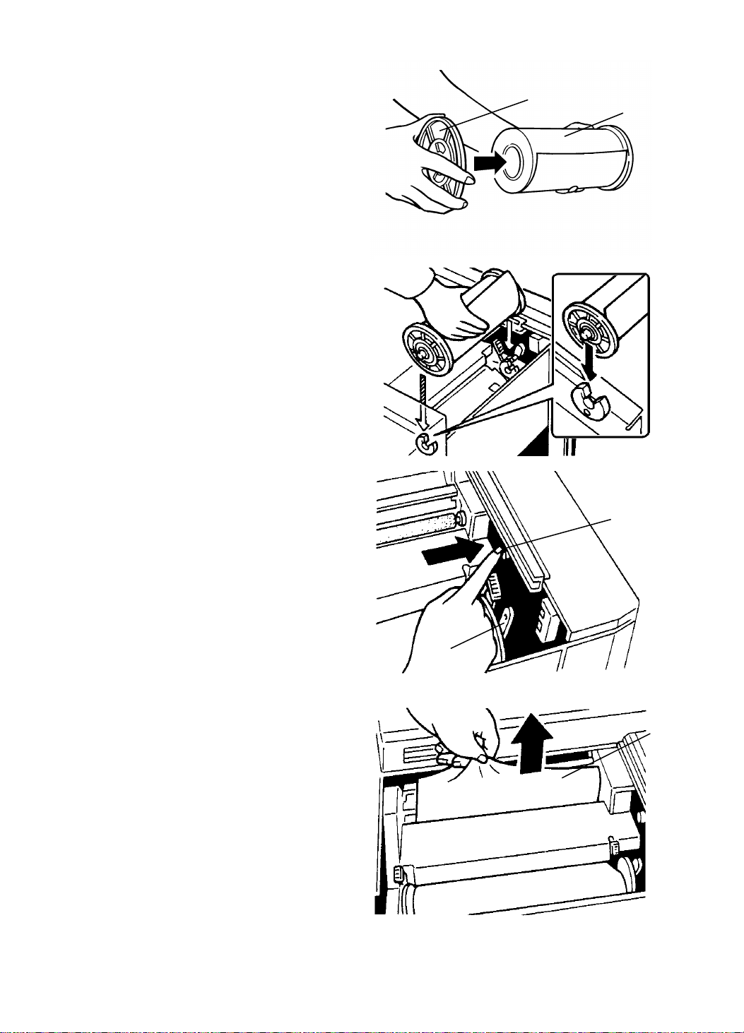
16. Install the master roll.
a. Slide the scanner unit all the
way to the left.
b. Attach a spool [A] to each
end of the master roll [B].
c. Push the pressure relea se
lever [C] to the left.
d. Set the master roll i n the
machine as shown in the
illustration.
e. Insert the leading edge of
the master roll under the
platen roller.
f. Return the pressure release
lever to the original position.
g. Plug in the power cord and
turn on the main switch.
h. Press the master cut butto n
[D].
[B]
[D]
i. Remove the cut strip [E] of
master paper.
NOTE: Confirm that the paper on
the master roll is not bent
or creased.
j. Close the scanner unit.
[C]
[E]
3-6
Page 41

15 July 1994 INSTALLATION PROCEDURE
[A]
[D]
[F]
[B][E]
[C]
17. Idle the machine to distribute ink on the drum.
a. Press the Reset key [A] while hold ing down the "0" key [B] on the
operati on panel.
b. If blinks on the operation pane l wh en the ma chin e stops, press the
Reset key again.
17. Make some test prints to check the machine.
a. Raise the platen cove r a nd place the origin al fa ce do wn on the
exposure glass [C]. Make sure the origin al is f lush with the left scale
and aligned with the proper paper size marks.
b. Press the Master Making key [D] .
c. Select the lowest print speed (1) with the Speed key [E] and press the
Print Start key [F]. Make prin ts at this spe ed unt il the print image
density stabilizes.
NOTE: 1. Usually, about 100 prints are made before the imag e fully
stabilizes.
2. Check the image qualit y aft er the print image density is
stabilized.
3-7
Page 42

SECTION 4
SERVICE TABLES
Page 43

15 July 1994 SERVICE TABLES
1. SERVICE TABLES
1.1 MAINTENANCE TABLES
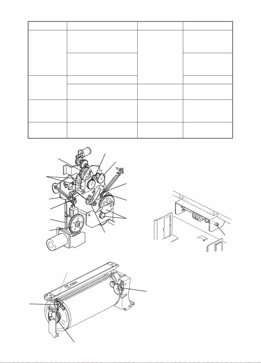
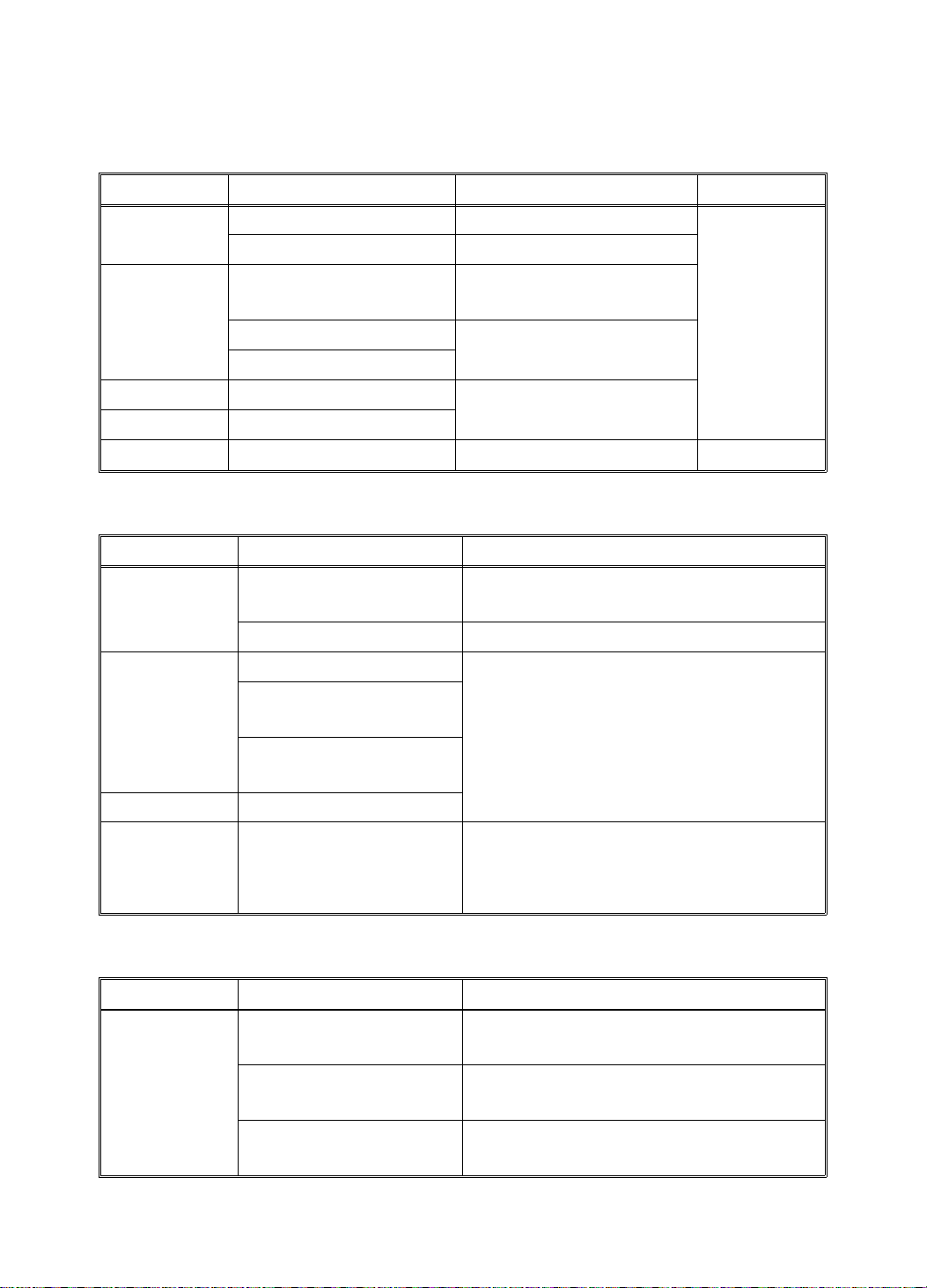
1.1.1 Lubrication Points
Lubricate after removin g ad hering ink and paper dust at yearly intervals.
Section Lubrication Point Type Location
Drive Speed Reduction Gear s
of the Main Motor
Gears of the Drum Drive
Shaft
Grease (Shell
Albania No. 2)
(Fig.1- E)
Inside and
outside of the
machine
(Fig.1- B)
Image
Positioning
Paper Feed Paper Feed Sector Gear (Fig.1- J)
Drum Drum Drive Gear Grease (Shell
Spiral Track of the Cam
Gear
Second Feed Sector
Gear
Gear of the Paper Feed
Cam Shaft
Paper Table Slide
Groove
Paper Table Drive Gear (Fig.1- G)
Bearings for the Upper
Separation Roller Shaft
Bearings for the Paper
Feed Roller Shaft
Master Clamper Sector
Gear
Master Clamper Pinion
Gear
Motor oil (SAE
No. 20)
Albania No. 2)
(Fig.1- K)
(Fig.1- F)
(Fig.1- A)
Both front side
and rear side
(Fig.1- H)
(Fig.1- I)
(Fig.2- L)
(Fig.3- N)
(Fig.3- O)
(Fig.3- P)
Printing
Pressure
Ink Pump Drive Gear (Fig.3- M)
Printing Pressure Arm
and Printing Pressure
Stay
Pressure Spring Link (Fig.1- C)
4-1
Both front side
and rear side
(Fig.4- Q)
Page 44
SERVICE TABLES 15 July 1994
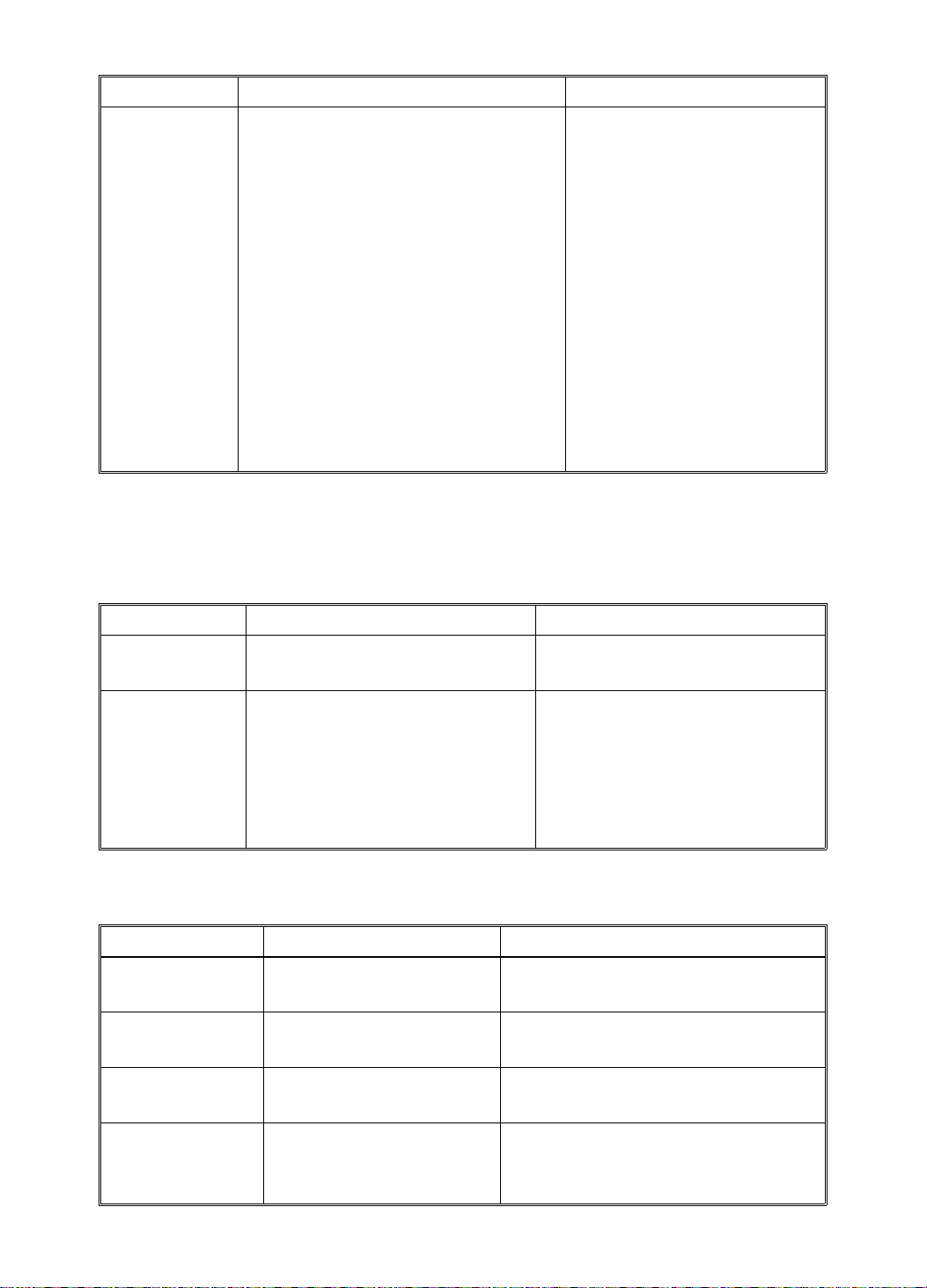
Section Lubrication Point Type Location
Master Eject Master Pressure Plat e
Grooves
Grease (Shell
Albania No. 2)
Both front side
and rear side
(Fig.5- S)
Edges of the Master
(Fig.5- R)
Pressure Plate Drive
Arms
Paper Exit Air Pump Drive Gears (Fig.6- T)
Inside of the Air Pump
Piston
ADF Bearings for the Feed
Roller Shaft
Grease (Mobil
Ep-1)
Motor oil (SAE
No. 20)
(Fig.6- U)
Both front and
rear side
(Fig.7- V)
Others Edge of Ea ch C a m Grease (Shell
(Fig.1- D)
Albania No. 2)
[Fig 1]
[K]
[D]
[A]
[B]
[C]
[Fig 2]
[O]
[Fig 3]
[J]
[I]
[H]
[G]
[P]
[F]
[D]
[E]
[L]
[M]
[N]
4-2
Page 45
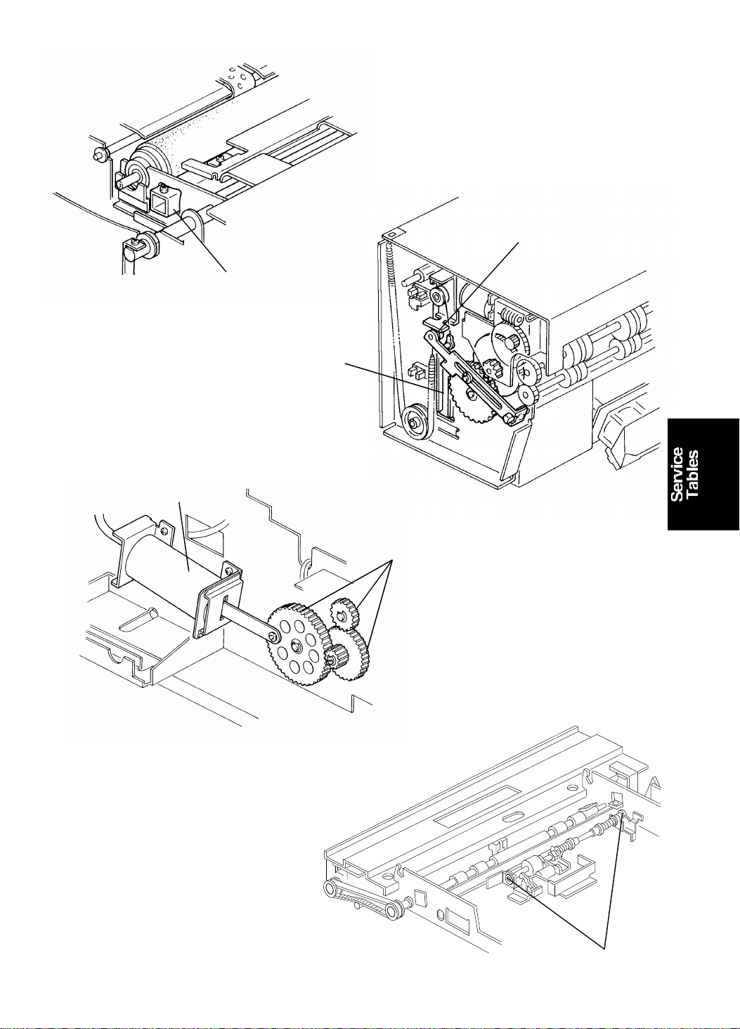
[Fig 7]
[Fig 5]
15 July 1994 SERVICE TABLES
[Fig 4]
[R]
[Q]
[S]
[Fig 6]
[U]
[T]
[V]
4-3
Page 46
SERVICE TABLES 15 July 1994
1.1.2 User’s Maintenance
Advise the customer to clean each item regularly. Clean the followin g ite ms
at every EM call if necessary.
Section Cleaning Point Cleaner Interval
Optics Original Platen Cover Cloth and water
Exposure Glass Cloth and glass cleaner
Paper Feed Paper Feed Roller Cloth and soap and
water
Paper End Sensor Dry cloth
At every
EM call
Paper Length Sensor
Printing Pre ss Roller Cloth and soap and
ADF Original Feed Rollers
water
Plotter Thermal Head Thermal head cleaner 500 masters
1.1.3 Table of Periodic Inspection (every 6 months)
Section Item Standard Procedure
Optics Original Platen Cover Wipe off the stains using a soft cloth
moistened with ethyl alcohol.
Exposure Glass Wipe with a dry cloth.
Paper Feed Paper Feed Roller Wipe off the ink and paper powder
Upper and Low e r
Second Feed Rollers
using a cloth moistened with ethyl
alcohol.
Upper and Low e r
Separation Rollers
Printing Press Roller
ADF Pick-up Roller
Feed Roller
Wipe off paper powder using a cloth
moistened with water.
Separation Roller
1.1.4 Table of Periodic Inspection (every 12 months)
Section Item Standard Procedure
Optics Back side of the
Wipe with a dry cloth.
Exposure Glass
Back side of the
Use a blower brush.
Mirror and Sub Mirror
Back side of the
Wipe with a dry cloth.
Fluorescent Lamp
4-4
Page 47

15 July 1994 SERVICE TABLES
Section Item Standard Procedure
Master Eject Upper and Lower
Master Eject Rollers
Wipe off the ink and paper powder
using a cloth moistened with ethyl
alcohol.
Master Eject Box Wipe off the ink using a cloth
moistened with ethyl alcohol.
Drum Inside and outside of
Drum
Ink Holder
Wipe off the built up ink and paper
powder using a cloth moistened with
ethyl alcohol.
Plotter Platen Roller Wipe off the paper powder using a
cloth moistened with water.
Others First and Second
Paper Exit Sensors
Master Eject Sensor
Check the performance of all the
sensors. Remove the stains from the
sensors using a dry cloth.
Drum Master
Detection Sensor
4-5
Page 48

SERVICE TABLES 15 July 1994
1.2 TABLE OF SERVICE CALL CODES
Code Problem Possible Causes
E-01 Neither th e righ t no r t he left
cutter switch turns off within 3
seconds of the cutter motor
starting.
E-02 Malfunction in the paper table
drive section.
The lower limit sensor or paper
table height sensor does no t turn
on within 7 seconds.
E-04 Temperat ure of th e thermal head
is greater than 54°C when th e
Master Making key is pressed.
E-05 Malfunction in the image shifting
section.
E-06 The drum rota tion sensor detects
an incorrect motor speed.
1) Drive wire cut
2) Drive section
malfunction
3) Defective cutter switch
1) Drive worm gear
broken
2) Mounting screw of the
worm gear broken
3) No power supply
1) Excessive thermal
head temperature
2) Thermistor short
1) Image position sensor
connector
disconnected
2) Defective image
position sensor
1) Drum lock
2) No power supply
E-07 Malfunction in the program.
When the main switch is turned
on, "E-07" lights up if the ROM is
defective.
E-08 Temperature of th e power sup ply
unit is greater than 85°C when
the Master Making key is
pressed.
E-09 The signal level between
CN109-A8 and GND is over 4.9
volts.
Defective ROM
Excessive power supply
unit temperature
1) Thermistor open.
2) Related connectors
are not connected
(Main PCB CN109-A8,
image processing
PCB CN404-B8/
CN403-22, or thermal
head drive PCB
CN705-22/ CN703-10).
4-6
Page 49

15 July 1994 SERVICE TABLES
Code Problem Possible Causes
E-10 The CPU detects an abnormality
in the pulse from the thermal
head drive PCB (ENR 1 to 4).
This pulse determines th e en erg y
applied to the therma l hea ting
elements.
E-11 Encoder output does no t change
within 3 seconds of the main
switch being turned on or the
Clear Mode key being pressed.
1) Defective thermistor
2) Related connectors
are not connected
(Main PCB CN109-A7,
image processing
PCB CN404-B7/
CN403-20, or thermal
head drive PCB
CN705-20).
3) No power supply for
ICs (Vcc) from power
supply unit to image
processing PCB
(disconnection of
image processing
PCB CN701-7/14, or
power supply unit
CN503-12/13).
1) Defective image
position motor
2) No power supply
E-12 1. The upper or lower pressure
plate sensor remains
activated for more th an 4
seconds after the pressu re
plate motor starts turning.
2. The lower pressure plate
sensor is not activated within
8 seconds of the pressure
plate motor starting to turn
even though the upper
pressure plate sensor is
de-activated.
3. The upper pressure plate
sensor is not activated for
more than 8 seconds after the
pressure plate motor starts to
turn even thoug h th e lower
pressure plate sensor is
de-activated.
Pressure plate drive
mechanism malfunction.
4-7
Page 50
SERVICE TABLES 15 July 1994
Code Problem Possible Causes
E-13 While the scanne r is going back
to the home position:
- The home position sensor
remains activated for more
than 4 seconds.
- The home position sensor is
not activated within 2
seconds.
- The home position sensor is
not activated within 7
seconds when the scanner
returns after finishing
making the master or
scanning.
1) Defective Home
Position Sensor
2) Scanner Motor Lock
1.3 TABLE OF DIP SW, LED, VR, TP (ON THE MAIN
CONTROL PCB)
1.3.1 DIP SW
No. DIP SW Function Remarks
DIP SW101 — Not used.
Must be OFF.
DIP SW102 Sets the initial setting for the
counter to incremen t by two
counts per print when the A3
drum is used. (This setting
can be changed by SP mode
No.86)
1.3.2 Photodiode
No. LED Component Remarks
LED101 1st Paper Exit Sensor When paper is detected, th e
LED102 Drum Master Detection
Sensor
LED103 2nd Paper Exit Sensor When paper is detected, the
LED104 Master Eject Sensor When the master is under the
Turn on to make the initial
setting for the counter
increment by two counts.
Normal: OFF for Ricoh/
AB Dick
ON for NRG
LED lights.
When the master is on the drum,
the LED lights.
LED lights.
master eject sensor, th e LE D
lights.
4-8
Page 51
15 July 1994 SERVICE TABLES
No. LED Component Remarks
LED105 Ink Detection When ink is present, the LED
lights.
LED106 Main Motor When the main motor turns on,
the LED lights.
1.3.3 VR
No. VR Function
VR101 1st Paper Exit Sensor Adjustment
VR102 Drum Master Detection Sensor Adjustment
VR103 2nd Paper Exit Sensor Adjustment
VR104 Master Eject Sensor Adjustment
1.3.4 TP
No. TP Function Standard Voltag e
TP101 1st Paper E xit Sensor Voltage ON: More than 2 V
OFF: 0.9 V
TP102 Drum Master Detection
Sensor Voltage
ON: More than 2 V
OFF: 0.9 V
TP103 2nd Paper Exit Sensor Voltage ON: More than 2 V
OFF: 0.9 V
TP104 Maste r Eject Sensor Voltage ON: More than 2 V
OFF: 0.9 V
TP105 Ink Detection Voltage ON (ink is present): 0 V
OFF: – 12 V
TP106 Drum Rotation Sensor Voltage ON: 0 V
OFF: 5 V
TP107 GND
4-9
Page 52
SERVICE TABLES 15 July 1994
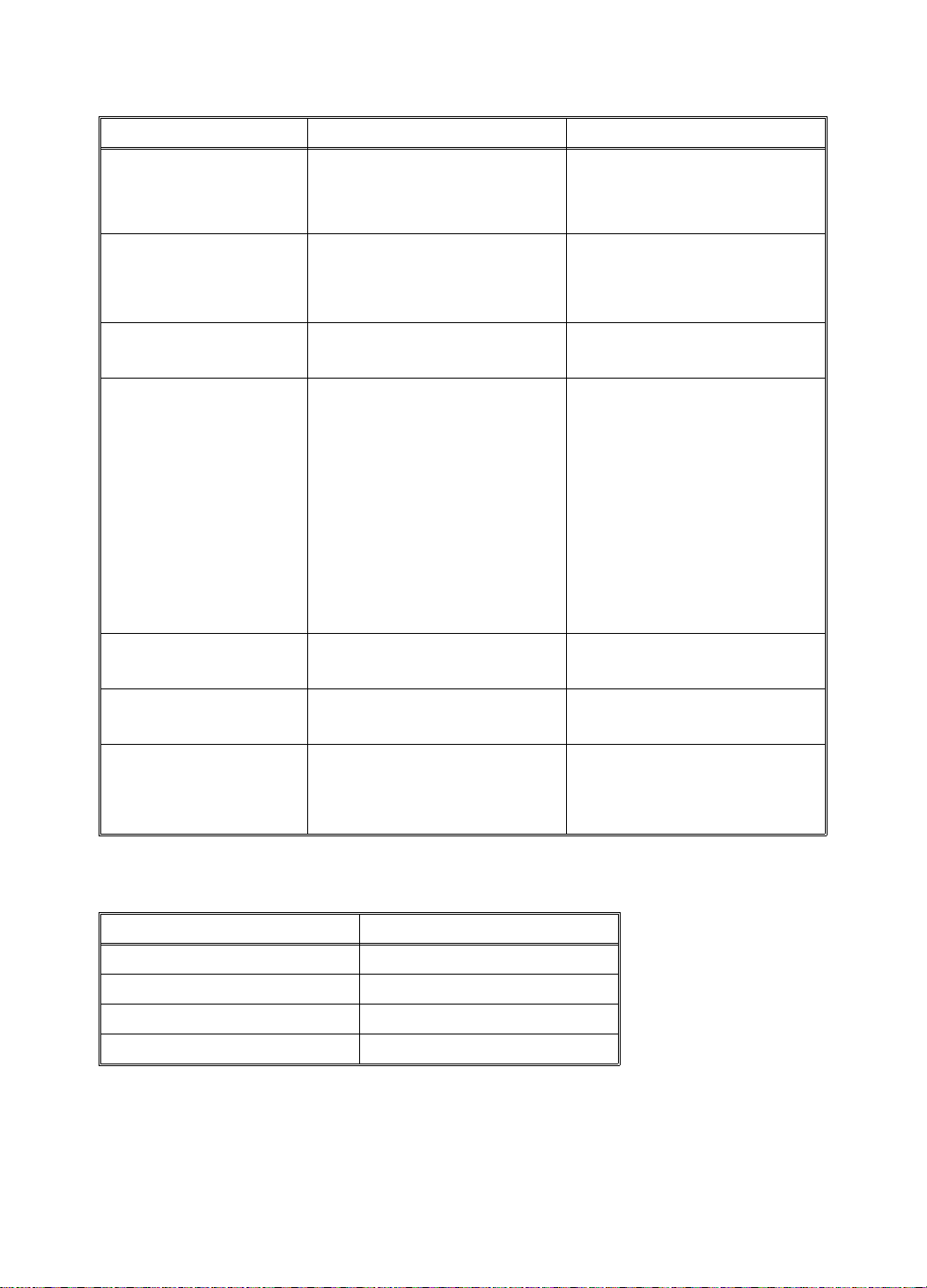
1.4 EXPECTED LIFE O F PARTS
Section Part Description Expected Life
Scanner Fluorescent La mp 15,000 originals
1st and 2nd Lower
Original Transport Rollers
Plotter/Master Feed Thermal Head 30,000 masters
Platen Roller 30,000 masters
Upper Master Feed Roller 1 year or 30,000 masters
Drum Drum Tetron Screen 2 years or 1,200,000
Paper Feed Paper Feed Rubbe r S ide
Plate
Paper Feed Roller 6 months or 300,000
Upper Separation Roller 1 year or 600,000 prints
Lower Separation Roller 2,000,000 prints
2nd Feed Roller Brake
Belt
Separation Plate 1 year or 600,000 prints
Printing Press Roller 2 years or 1,200,000
Delivery Transport Belt 2 years or 1,200,000
1 year or 60,000 originals
prints
1,200,000 prints
prints
1,000,000 prints
prints
prints
ADF Pick-up Roller 60,000 originals
Original Feed Roller 3 0,00 0 originals
Separation Roller 60,000 originals
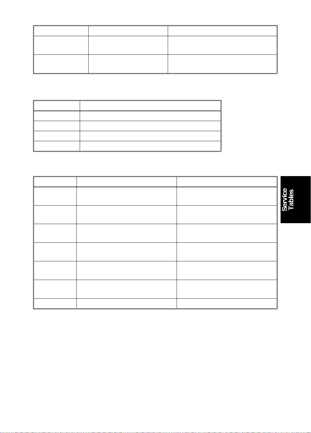
1.5 SPECIAL TOOLS
Description Part Number
Test Chart R-21 99992131
Resolution Chart A0129110
Drum Gauge C2009001
Image Shifting Gauge C2009002
4-10
Page 53

15 July 1994 SERVICE PROGRAM MODE
2. SERVICE PROGRAM MODE
2.1 SERVICE PROGRAM MODE OPERATION
The service program (SP) mode is used to check electrical data, change
modes, or change adjust men t values.
2.1.1 Service Program Mode Access Procedure (for engineers)
All service program modes can be accessed with this procedure.
1. Press the following keys on the operation panel in the following order:
Case 1:
a) Clear Modes key
b) Clear key
c) Combine 2 Originals key
d) Enter key
Case 2:
a) Turn off the power switch
b) Press the Enter key, Stop key, and Clear key simult an eo usly
c) Turn on the power
2. The following is displayed on the LCD when the SP mode is acce ssed .
SP–MODE
PROGRAM No. 0
3. Using the number keys, enter the desired SP mode number (listed in the
service program table.)
NOTE: The SP mode nu mb er can be shifted up or down by pressing the
Zoom key ("+" or "–").
4. To cancel the SP mode, press the Clea r Mo des key.
4-11
Page 54

SERVICE PROGRAM MODE 15 July 1994
2.1.2 Service Program Mode Access Procedure (for users)
This procedure allows users to access only the service pro gra m modes tha t
are marked with an asterisk in the service program table.
1. Press the following keys on the operation panel in the following order:
a) Clear Modes key
b) Clear key
c) Enter key
2. The following is displayed on the LCD when the SP mode is acce ssed .
SP–MODE
PROGRAM No. 0
3. Using the number keys, enter the desired SP mode number (listed in the
service program table).
4. To cancel the SP mode, press the Clea r Mo des key.
2.1.3 Change Adjustment Values or Modes
1. After entering the desire d SP mode number, press the Enter key. The
value or mode set at the factory will be displayed on the LCD (at the end
of the second line).
2. Enter the desired value or mode using the number keys (listed in the
service program table).
3. Press the Enter key to sto re th e de sired value or mode.
4. To cancel the SP mode, press the Clea r Mo des key.
4-12
Page 55

15 July 1994 SERVICE PROGRAM MODE
2.2 DIFFERENCE IN SP MODE S BETWEEN THE #C210
MODEL AND THE #C218/C219 MO DELS
2.2.1 NEW SP MODES
SP mode No.5 Setting the number of EMF sorters.
SP mode No. 24 Character Emphasis setting. (Only for the C219 model.)
SP mode No. 36 Sub-scan magnification adjustment (ADF mode).
SP mode No. 37 Threshold value adjustment for shadow erase.
SP mode No. 38 ADF scan line adjustment
SP mode No. 39 Image center adjustment.
SP mode No. 84 Initial mode for Combine 2 Originals.
SP mode No. 85 Master full detection at power-up.
SP mode No. 86 Counter setting for the A3 drum. (Only for the C218 model.)
SP mode No. 87 Mode setting for Memory mode.
SP mode No. 88 Setting the print mode.
SP mode No. 92 Thermal Paper Mode.
SP mode No. 93 Shadow erase area check.
SP mode No. 95 Scanner free run mode.
SP mode No. 96 ADF original feed test mode.
SP mode No. 115 ADF mode counter.
SP mode No. 116 Platen mode counter.
SP mode No. 117 Color drum counter.
SP mode No. 118 Each paper size counter.
SP mode No. 119 All total counter clear mode.
SP mode No. 135 1st paper exit sensor voltage.
SP mode No. 136 2nd paper exit sensor voltage.
SP mode No. 137 Master eject sensor voltage.
SP mode No. 138 Drum master sensor voltage.
SP mode No. 142 Paper size detection On/Off.
SP mode No. 147 ADF set detection On/Off.
SP mode No. 160 to
170
Margin erase dimension settings.
2.2.2 ELIMINATED SP MODES
SP mode No. 50 Settings for directional magnification mode.
SP mode No. 109 Directional magnification counter.
SP mode No. 112 Clear Total Master/Print counter.
4-13
Page 56

SERVICE PROGRAM MODE 15 July 1994
2.3 SERVICE PROGRAM TABLE
*: Accessible by a customer ♥: A4 version ♦: LT version
No. Display Function Data Factory
Setting
1. On line Enables On Line
key operation.
2. FDC Type 10 Used only in Japan 0: No
0: No
1: Yes
0OO
0 Keep at 0. O O
1: Yes
3. Key Counter Enables key
counter operation.
4. Key Card Used only in Japan. 0: No
0: No
1: Yes
0OO
0OO
1: Yes
5. EMF Sorter Selects the number
of sorters.
0: No sorters
1, 2, 3, 4, or
0 Input 1 to 5
5: Sorters
present
*10. Min. Print Limits the minimum
0 to 9999 0 O O
print quantity that
can be entered.
*11. Max. Print Limits the maximum
0 to 9999 9999 O O
print quantity that
can be entered.
*12.
*12.
*13.
*14.
♥: A4 → A3
Mag. Ratio
♦: HLT → LG
Mag. Ratio
♥: B5 → B4
Mag. Ratio
♦: HLT → LG
Mag. Ratio
♥: A4 → B4
Mag. Ratio
♦: LT → DLT
Mag. Ratio
♥: B4 → A3
Mag. Ratio
♦: LG → DLT
Mag. Ratio
Adjusts the fixed
magnification ratio.
♥: From A4 to A3
♦: From 5
1/2" to 81/2" x 14"
8
1/2" x
Adjusts the fixed
magnification ratio.
♥: From B5 to B4
♦: From 5
1/2" to 81/2" x 14"
8
1/2" x
Adjusts the fixed
magnification ratio.
♥: From A4 to B4
♦: From 5
1/2" to 11" x 17"
8
1/2" x
Adjusts the fixed
magnification ratio.
♥: From B4 to A3
♦: From 8
1/2" x 14"
50 to 200%
50 to 200%
50 to 200%
50 to 200%
♥:
141%
♦:
155%
♥:
141%
♦:
155%
♥:
122%
♦:
129%
♥:
115%
♦:
121%
to 11" x 17"
*14.
♥: B5 → A4
Mag. Ratio
♦: LG → DLT
Mag. Ratio
Adjusts the fixed
magnification ratio.
♥: From B5 to A4
♦: From 8
1/2" x 14"
50 to 200%
♥:
115%
♦:
121%
to 11" x 17"
Comments C218 C219
OO
to indicate
the number
of sorters.
O
O
OO
O
O
4-14
Page 57

15 July 1994 SERVICE PROGRAM MODE
No. Display Function Data Factory
Setting
*15. Full Size Adjusts the full size
50 to 200% 100% O O
magnification ratio.
*16. Page Margin Adjusts the create
50 to 200% 93% O O
margin
magnification ratio.
*17.
*18.
♥: A3 → B4
Mag. Ratio
♦: LG → LT
Mag. Ratio
♥: B4 → A4
Mag. Ratio
♦: ** → LT
Mag. Ratio
Adjusts the fixed
magnification ratio.
♥: From A3 to B4
♦: From 8
to 8
1/2" x 14"
1/2" x 11"
Adjusts the fixed
magnification ratio.
♥: From B4 to A4
♦: From 11" x 15"
50 to 200%
50 to 200%
♥: 87%
♦: 77%
♥: 82%
♦: 74%
to
1/2" x 11"
8
*19.
♥: A3 → A4
Mag. Ratio
♦: DLT → LT
Mag. Ratio
Adjusts the fixed
magnification ratio.
♥: From A3 to A4
♦: From 11" x 17"
50 to 200%
♥: 71%
♦: 65%
to
1/2" x 11"
8
*19.
♥: B4 → B5
Mag. Ratio
♦: DLT → LT
Mag. Ratio
Adjusts the fixed
magnification ratio.
♥: From B4 to B5
♦: From 11" x 17"
50 to 200%
♥: 71%
♦: 65%
to
1/2" x 11"
8
*20. Buzzer On Turns the beeper
ON or OFF
*21. Prints/Master
Cost
Adjusts the ratio of
masters to prints.
0: No
0OO
1: Yes
0 to 50 0 The set
For accounting
purposes.
22. Read Image
Not used
—
0 Not used O O
Area
*23. Online
Paper Size
*24. Character
Emphasis
Used only in Japan 0: A6
1: A5
Use this to make
text more clear
when using Photo
mode.
0: No
1: Slightly
High
2: High
0 Not used O
0O
Comments C218 C219
OO
OO
O
O
OO
number (0
to 50) is
automatically
added to
the key
counter
each time a
master is
used.
4-15
Page 58

SERVICE PROGRAM MODE 15 July 1994
No. Display Function Data Factory
Setting
30. Sub Scan
Mag. Adjust
31. MTF Level Adjusts the MTF
32. Image
Density Rank
33. Lead Edge
Margin
35. Head
Energy
Adjust
36. Sub Scan
Mag. Adjust
(ADF)
37 Shadow
Erase Level
37-0 Line Use to adjust the threshold value for shadow erase in Line
37-1 Photo Use to adjust the threshold values for each of the contrast
37-1-0Std (Normal) Adjusts the shadow
37-1-1Lt (Light
Tone)
Adjusts the
sub-scan
magnification.
level.
In line mode,
adjusts the image
density level.
Adjusts the lead
edge margin.
Adjusts the thermal
head energy.
Adjusts the ADF
sub-scan
magnification.
Use to adjust the
threshold levels for
shadow erase in
the various image
modes.
mode. There are four numbers. Each represents the
threshold value for an image density. Input the required
value for the one that is blinking, then press Enter to move
on to the next one.
The lower the value, the darker the printout will be. The
factory settings are 27 for Light, 23 for Standard, 21 for
Dark, and 17 for Darker.
settings for shadow erase in Line mode. There are three
sub-menus to choose from. These are 0: Standard
(Normal), 1: Light Tone, and 2: Dark Tone (see below).
erase threshold
level for the Normal
contrast setting in
Line mode
Adjusts the shadow
erase threshold
level for the Light
Tone contrast
setting in Line mode
–1.9 to
+1.9%
0: Low
1: Standard
2: High
3: Maximum
0: Light
1: Standard
2: Dark
4 to 10 mm 8 mm O O
0 to –99% –7% 1% steps O O
-1.9 to 1.9% 0 0.1% steps O O
0: Line
1: Photo
2: Clear
Defaults
31: Light
25: Standard
17: Dark
15: Darker
Defaults
31: Light
25: Standard
17: Dark
15: Darker
(0) The factory
Comments C218 C219
setting
depends on
the
machine.
1OO
1OO
OO
OO
OO
OO
OO
OO
4-16
Page 59

15 July 1994 SERVICE PROGRAM MODE
No. Display Function Data Factory
Setting
37-1-2Dk (Dark
Tone)
37-2 Clear Returns all the
38. ADF Scan
Line Adjust
39 Image
Center
Adjustment
39-0 Image
Center
Adjustment:
Scanner
39-1 Image
Center
Adjustment:
ADF
*40. Original Specifies the image
*41. Image
Density
42. Print Speed Specifies the
*43. Auto Cycle
Mode
Adjusts the shadow
erase threshold
level for the Dark
Tone contrast
setting in Line mode
settings for SP
mode 37 to the
defaults.
Adjusts the ADF
scanning start
position.
Adjusts the center
position of copies in
the ADF and platen
modes.
Adjusts the center
position of copies in
platen mode.
Adjusts the center
position of copies in
ADF mode.
mode at power-up.
Specifies the image
density at power-up.
printing speed at
power-up.
Specifies whether
Auto Cycle mode is
selected at
power-up.
Defaults
17: Light
13: Standard
7: Dark
3: Darker
-4.9 to 4.9
mm
0: Scanner
1: ADF
-0.9 to 0.9
mm
-4.9 to 4.9
mm
0: Photo
1: Line
2: Sharpen
0: Light
1: Standard
2: Dark
3: Darker
[C218 model]
0: 60 rpm
1: 75 rpm
2: 90 rpm
3: 105 rpm
4: 120 rpm
[C219 model]
0: 60 rpm
1: 75 rpm
2: 90 rpm
3: 110 rpm
4: 130 rpm
0: No
1: Yes
0 0.1 mm
0See
0 0.1 mm
0 0.1 mm
1OO
1OO
2OO
0OO
Comments C218 C219
OO
OO
OO
steps
See
remarks (1).
OO
remarks (2).
OO
steps
OO
steps
4-17
Page 60

SERVICE PROGRAM MODE 15 July 1994
No. Display Function Data Factory
Setting
*44. Memory/Class
Mode
45. Std. Image
Position
*46. Make Up Specifies the initial
47. Contrast Specifies the initial
48. Photo Specifies the initial
60. Clear All
Memory
70. Original
Feed Jam
(A)
71. Paper Feed
Jam (B)
72. Paper Wrap
Jam
(E)/(B)(E)
73. Paper
Delivery
Jam (G)
74. Master Feed
Jam (C)
Specifies the initial
job memory feature
(Memory or Class
mode) at power-up.
Specifies the image
position at power-up
make-up
background pattern
when the Image
Make-up mode is
selected.
contrast when the
Photo mode is
selected.
screen when the
Photo mode is
selected.
Returns all SP
modes to the
factory settings.
Displays the total
number of original
jams.
Displays the total
number of paper
feed jams.
Displays the total
number of times
that paper has
wrapped around the
drum.
Displays the total
number of paper
delivery jams.
Displays the total
number of master
feed jams.
0: Class
1: Memory
0: –20 mm
1: –15 mm
2: –10 mm
3: –5 mm
4: 0 mm
5: +5 mm
6: +10 mm
7: +15 mm
8: +20 mm
1 to 40
51 to 90
101 to 140
150 to 190
0: Standard
1: Light
2: Dark
0: Standard
1: Fine
2: Coarse
0: No
1: Yes
1OO
4OO
0 0: No
0OO
0OO
0OO
0OO
0OO
0OO
0OO
0OO
Comments C218 C219
OO
background
pattern is
selected.
4-18
Page 61

15 July 1994 SERVICE PROGRAM MODE
No. Display Function Data Factory
Setting
75. Master
Delivery
Jam (F)
76. Clear Jam
Counters
81. Proof Print
No.
*82.-1Skip Feed
No.
-2 Long Sheet Specifies whether a
*83. Auto Reset
Time
*84. Auto
Combine 2
Orig.
*85. Initial Full
Check
86. A3 Drum 2
Count Up
Displays the total
number of master
delivery jams.
Clears all jam
counters.
Specifies how many
trial prints are made
after making the
master.
Selects the feed
interval.
long sheet is used.
Specifies the auto
reset time.
Specifies the initial
mode for Combine
2 Originals.
Specifies whether
master full
detection is made
at power-up.
Specifies whether
the counter
increments by two
counts per print
when the A3 drum
is used.
0OO
0: No
1: Yes
0 to 2 sheets 1 O O
1 to 5 1 1: Normal
0: No
1: Yes
0: No
1: 3 min.
2: 5 min.
0: Normal
1: Auto (Two
identical
images are
made if the
Master
Making key
is pressed
once.)
0: No
1: Yes
0: No
1: Only the
master
counter
2: Both the
master and
the copy
counter
0OO
0 Displays
0OO
0OO
0OO
0
Ricoh,
AB Dick
2
NRG
Comments C218 C219
OO
operation
2 to 5: One
sheet fed
every two
to five drum
rotations
OO
only when
no. 2, 3, 4,
or 5 are
selected in
82-1.
See
Remarks (3)
O
4-19
Page 62

SERVICE PROGRAM MODE 15 July 1994
No. Display Function Data Factory
Setting
87. Memory Print Specifies the print
mode when in
Memory mode.
88 Auto
Memory/
Class
90. Thermal
Head Test
91. Command
Sheet Check
92. Thermal
Paper Mode
93. Erase Area
Check
95.
Scanner
-1
Free Run
-2 Scanner
Free Run
96. ADF Original
Feed Check
100. Combine 2
Originals
Count
101. Make Up
Count
Specifies the print
mode.
Selects the
background pattern
for the copy made
in the thermal head
test; performs the
test.
Prints the command
sheet image
(designated area)
together with the
original image.
Use this mode to
test the thermal
head.
Checks the erase
area.
Selects free running
of the scanner.
Carries out the
scanner free run.
(The speed can be
changed: see
remarks (8).)
Carries out the ADF
original feed check.
(The speed can be
changed; see
remarks (9).)
Displays the total
number of masters
made in Combine 2
Original mode.
Displays the total
number of masters
made in Make-up
mode.
0: Normal
(Memory
Print Mode)
1: Stack
Mode
0: Normal
1: Auto
Class
(Memory)
Print
1 to 40
51 to 90
101 to 140
150 to 190
0: No
1: Yes
0: No
1: Yes
0: No
1: Yes
0: With the
lamp off
1: With the
lamp on
Start with
the Print
Start key.
Stop with the
Stop key.
Start with
the Print
Start key.
Stop with the
Stop key.
0See
0See
7 See the
0 See the
0See
0See
0See
0OO
0OO
Comments C218 C219
OO
Remarks (4)
OO
Remarks (5)
OO
Thermal
Head Test
section.
Command
Sheet
Check
section.
Remarks (6)
Remarks (7)
Remarks (8)
Displays by
pressing #,
after
selecting 0
or 1 in 95-1.
See
Remarks (9)
(Only
one
patte
rn)
OO
OO
OO
OO
OO
OO
4-20
Page 63
15 July 1994 SERVICE PROGRAM MODE
No. Display Function Data Factory
Setting
102. Make Up
Photo Count
103. Area Mask
Count
104. On line
Count
105. Overlay
Count
106. Enlarge
Count
107. Reduction
Count
108. Zoom Count Displays the total
110. Power On
Time
111. Total Count Displays the total
*113. Resettable
Count
*114. CLR Reset
table Count
115. ADF Mode
Count
Displays the total
number of masters
made in Make-up
Photo mode.
Displays the total
number of masters
made with the
Margin Erase key.
Displays the total
number of masters
made in On Line
mode.
Used only in Japan. 0 O O
Displays the total
number of masters
made in Fixed
Enlargement mode.
Displays the total
number of masters
made in Fixed
Reduction mode.
number of masters
made in Zoom
mode.
Displays the total
amount of time the
machine has been
turned on.
number of masters
and prints.
Used by the
customer to display
the total number of
masters and prints.
Clears the
resettable total
master/print
counters.
Displays the total
number of sheets
fed in the ADF
mode.
0: No
1: Yes
0OO
0OO
0OO
0OO
0OO
0OO
0 xxxxx Hour
0 M: Master
0 M: Master
0OO
0OO
Comments C218 C219
OO
xx Min.
xx Sec.
OO
count
P: Print
count
OO
count
P: Print
count
4-21
Page 64

SERVICE PROGRAM MODE 15 July 1994
No. Display Function Data Factory
Setting
116. Platen Mode
Count
117. Color Drum
Count
118. Paper Size
Count
119. CLR All
Total Count
*120.
User Code
-1
Mode
-2 Auto Reset
Time
*121. UC Count Displays the total
*122. Clear UC
Count
*123. Total UC
Count
*124. Clear Total
UC Count
130. Input Check
Mode
131. Output
Check Mode
Displays the total
number of originals
set in platen mode.
Displays the total
number of prints
when using the
color drum.
Displays the total
number of prints
made in each paper
size.
See Remarks (10).
Clears the following
counters:
Nos. 111, 115, 116,
117, and 118.
Selects user code
mode, and displays
the total number of
prints made in the
User Code mode.
Selects the auto
reset time.
number of masters
and prints made by
each user code.
Clears every user
code counter.
Displays the total
number of masters
and prints for up to
20 user codes.
Clears the total
user code counter.
Displays the input
from sensors and
switches.
Turns on the
electrical
components.
0: No
1: Yes
0: No
1: Yes
0: Unlimited
1: 3 min.
2: 5 min.
0: No
1: Yes
0: No
1: Yes
0OO
0OO
0 Display
0OO
0 See the
0 Displays
0 Press the #
0 Same as
0OO
0OO
Comments C218 C219
OO
counters
for each
paper size
by pressing
the # key.
OO
user code
mode
section.
OO
only when
"Yes" is
selected in
120-1.
OO
key to shift
to another
user code.
OO
above.
See the
input check
table.
See the
output
check table.
OO
OO
4-22
Page 65

15 July 1994 SERVICE PROGRAM MODE
No. Display Function Data Factory
Setting
132. All IndicatorsONTurns on all the
indicators on the
operation panel.
135. SN: 1st
Paper Exit
136. SN: 2nd
Paper Exit
137. SN: Master
Eject
138. SN: Drum
Master
140. Ink Detection Specifies whether
141. Paper
Detection
*142.-1Paper Size
Detection
-2 Size
Indication Off
*143. Orig. Size
Detection
145. Drum Mast.
Detection
146. ADF Cover
Detection
147. Platen Set
Detection
Displays the 1st
paper exit sensor
voltage.
Displays the 2nd
paper exit sensor
voltage.
Displays the master
eject sensor voltage.
Displays the drum
master sensor
voltage.
ink detection is
done.
Specifies whether
paper end detection
is done.
Selects paper size
detection.
Specifies whether
the paper size
indication on the
operation panel is
erased.
Specifies whether
original size
detection is done.
Specifies whether
drum master
detection is done.
This mode disables
the ADF Cover
Sensor detection.
This mode disables
the ADF Set Sensor
detection.
0: No
1: Yes
0: No
1: Yes
0: Yes
1: Width
detection
only
2: Length
detection
only
3: No
detection
0: No
1: Yes
0: No
1: Yes
0: No
1: Yes
0: Disabled
1: Enabled
0: Disabled
(the ADF is
always set)
1: Enabled
1OO
1OO
0OO
0 Displays
1O
1OO
1OO
1OO
Comments C218 C219
Press the #
key to light
all the
indicators.
Unit: Volts O O
Unit: Volts O O
Unit: Volts O O
Unit: Volts O O
only when
1, 2, or 3 is
selected in
142-1.
OO
OO
4-23
Page 66

SERVICE PROGRAM MODE 15 July 1994
No. Display Function Data Factory
Setting
150. Control
ROM No.
Displays the ROM
part number and
P/No. 1994/10/07
the ROM
manufacturing date.
151. Machine No. Displays the
0 Input the
machine serial
number and the
installation date.
152. Service Tel.
No.
Input the service
representative’s
0 Use the
telephone number,
which is displayed
with the service call
code.
153. Last Service
Code
*160.
♥: Area
Mask A3 ❑
♦: Area
Mask
11x17❑
Displays the last
service call.
Adjust the margin
erase area.
♥: A3
♦: 11" x 17"
(50 to 307) x
(50 to 432)
mm
0OO
♥: 289
x416mm
♦: 271
x428mm
Comments C218 C219
OO
=
YYYY/MM/D
D
OO
serial
number
and the
installation
date.
OO
number
keys to
input the
telephone
number at
installation.
Press the
Memory/
Class key
to add a
space
between
the digits.
OO
*161.
*162.
♥: Area
Mask B4 ❑
♦: Area
Mask
8.5x14❑
♥: Area
Mask A4 ❑
♦: Area
Mask
8.5x11 ❑
Adjust the margin
erase area.
♥: B4
1/2" x 14"
♦: 8
Adjust the margin
erase area.
♥: A4 Landscape
1/2" x 11"
♦: 8
Landscape
(50 to 307) x
(50 to 432)
mm
(50 to 307) x
(50 to 432)
mm
4-24
♥: 249
x360mm
♦: 208
x352mm
♥: 202
x293mm
♦: 208
x275mm
OO
OO
Page 67

15 July 1994 SERVICE PROGRAM MODE
No. Display Function Data Factory
Setting
*163.
*164.
*165.
*166.
♥: Area
Mask A4 ❑
♦: Area
Mask
8.5x11 ❑
♥: Area
Mask B5 ❑
♦: Area
Mask
5.5x8.5 ❑
♥: Area
Mask B5 ❑
♦: Area
Mask
5.5x8.5 ❑
♥: Area
Mask A5 ❑
♦: Area
Mask **1 ❑
Adjust the margin
erase area.
♥: A4 Portrait
1/2" x 11"
♦: 8
Portrait
Adjust the margin
erase area.
♥: B5 Landscape
1/2" x 81/2"
♦: 5
Landscape
Adjust the margin
erase area.
♥: B5 Portrait
1/2" x 81/2"
♦: 5
Portrait
Adjust the margin
erase area.
♥: A5 Landscape
♦: 2" x 2"
(50 to 307) x
(50 to 432)
mm
(50 to 307) x
(50 to 432)
mm
(50 to 307) x
(50 to 432)
mm
(50 to 307) x
(50 to 432)
mm
♥: 289
x206mm
♦: 271
x212mm
♥: 174
x253mm
♦: 132
x212mm
♥: 249
x178mm
♦: 208
x136mm
♥: 140
x206mm
♦: 50x
50mm
*167.
♥: Area
Mask A5 ❑
♦: Area
Mask **2 ❑
Adjust the margin
erase area.
♥: A5 Portrait
♦: 2" x 2"
(50 to 307) x
(50 to 432)
mm
♥: 202
x144mm
♦: 50x
50mm
*168.
*169.
♥: Area
Mask A6 ❑
♦: Area
Mask **3 ❑
♥: Area
Mask A6 ❑
♦: Area
Mask **4 ❑
Adjust the margin
erase area.
♥: A6 Landscape
♦: 2" x 2"
Adjust the margin
erase area.
♥: A6 Portrait
♦: 2" x 2"
(50 to 307) x
(50 to 432)
mm
(50 to 307) x
(50 to 432)
mm
♥: 97x
144mm
♦: 50x
50mm
♥: 140
x101mm
♦: 50x
50mm
*170.
♥: Area
Mask ** ❑
♦: Area
Mask **5 ❑
Adjust the margin
erase area.
♥: Others
♦: 2" x 2"
(50 to 307) x
(50 to 432)
mm
♥: 92x
144mm
♦: 50x
50mm
Comments C218 C219
OO
OO
OO
OO
OO
OO
OO
OO
4-25
Page 68

SERVICE PROGRAM MODE 15 July 1994
Remarks
1) SP-Mode No. 38 − ADF Scan Line Position
The printing position moves as sho wn be low.
← Directio n
Original Position
+X: Inputs +X mm
Printing Position
-X: Inputs -X mm
Printing Position
X mm
4-26
Page 69

15 July 1994 SERVICE PROGRAM MODE
2) SP-Mode No. 39 – Image Center Position
The printing position moves as sho wn be low.
← Directio n
Original Position
X mm
+X: Inputs +X mm
Printing Position
-X: Inputs -X mm
Printing Position
Note: In the case of image position adjustment of the scanner ,
input "0" first;
Example) X = 0.9 mm → "0", "9", and then press the #
key.
3) SP-Mode No. 86 – A3 Drum 2 Count Up
The counter increment goes up by 2 if an A3 drum is insta lled , reg ardless of
the size of paper.
The default setting is chang ed with DIP switch 10 2. See page 4-8 for de ta ils.
4-27
Page 70

SERVICE PROGRAM MODE 15 July 1994
4) SP-Mode No. 87 – Memory Print
Set this mode to Memory to print a different number of prints from each
original. The machine stop s aft er prin ting each group. You must press the
Print Start key each time to go on to print the next grou p. When all print ing is
finished, the input data is cleared.
Set this mode to Stack to print a dif fe ren t nu mbe r of prints from only one
original. The machine prints all printing groups continuously, without feeding
tape from the tape dispenser. When all printing is finished, the input data is
stored in the machine .
5) SP-Mode No.88 – Auto Memory/Class
Set this mode to Yes to let the machine print all groups con tin uo usly without
installing a tape dispenser.
6) SP Mode 92 – Thermal Paper Mode
You can use this mode to test the thermal head.
Place the thermal paper in the plotter face down and change this SP Mode to
1. Place an original on the exposure glass and pre ss t he Master Making key.
The machine starts plot ting on the thermal paper without doin g the master
clamp process.
You can also enable SP Mode 90 and press th e Master Making key to do the
same procedure without placing an original on the exposure glass.
7) SP Mode 93 – Erase Area Check
This checks the erased area for shadow erase (Center and Edge Ma rgin
Erasing). If you make a master an d prin t an image with th is mo de, the
machine makes a background pattern on the area to be erased.
4-28
Page 71

15 July 1994 SERVICE PROGRAM MODE
8) SP-Mode No. 95 – Scanner Free Run
•
It is possible to change the first scan ne r sp eed by changing the
magnification ratio:
25 to 200 % (Maximum spe ed = 25 %)
•
To start scanner free run, pre ss the Print Start key after selecting
"Lamp On/Off" using the # key.
Input a magnification ratio if you wish to change the first scan ne r
speed, before you press the Start key. (Factory setting = 25 %)
•
To stop the scanner free run, pre ss the Stop key. The scanner returns
to home position, then stops.
•
The machine does not exit SP mode until the scann er ret urns to home
position correctly.
9) SP-Mode No. 96 – ADF Original Feed Check
•
It is possible to change the origin al feed speed, by changing th e
magnification ratio:
25 to 200 % (Maximum spe ed = 25 %)
•
To start original feed, pre ss the Print Start key after placing originals in
the ADF.
Input a magnification ratio if you wish to change the original feed
speed, before you press the Start key. The ADF starts feeding until all
originals are fed.
•
To stop feeding, press the Stop key. The original stops at this moment.
•
If the original feed fails, or if the Stop key is pressed, th e "A + Jam"
indicator turns on.
If the failed originals are remo ved from the ADF, the jam indicator
turns off and the failure is reset.
•
The machine does not exit SP mode during feeding.
10) SP-Mode No. 118 – Print Size Count
•
The print size counter indicat es th e followin g pa per size s:
A4 version LT version
• A3 • DLT
• B4 • LG
• A4 Landscape • LT Landscape
• A4 Portrait • LT Portrait
• B5 Landscape • HLT
• B5 Portrait • * (Others)
• * (Others)
11) Others
•
Use the Memory/Class key if you wish to change +/-.
4-29
Page 72

B
SERVICE PROGRAM MODE 15 July 1994
2.4 THERMAL HEAD TEST
This function is used to determine which printer component is causing an
image problem on the master.
In this mode, the background patt ern that is printed covers the entire sheet of
paper.
Procedure
1. Place paper on the paper table.
NOTE: To reduce th erma l hea d loa d, use th e smalle st pape r size possib le,
i.e. the smallest size on which the area with the image proble m can
be printed.
2. Access SP mode.
3. Input No. 90 and press the En ter key.
NOTE: The fa cto ry setting is pattern No. 7. If ne cessa ry, input another
background pattern with the Number keys.
4. Press the Master Making key (an origin al is not nece ssary).
5. Make prints and check the image.
Assessment
If the pattern image is normal, a Pa rt A comp on ent is def ective.
If the pattern image is abnormal, a Pa rt B component is defective.
A
Fluorescent Lamp
CCD
PCB
Original
Transport
Motor
A/D
Conversion
PCB
Image
Processing
PCB
Thermal Head
Drive PCB
Master Feed
Motor
Thermal
Head
•
This mode can be used in combination with th e SP mode No. 92 , The rmal
Paper Mode. See Page 4-20 for details.
4-30
Page 73

15 July 1994 SERVICE PROGRAM MODE
2.5 COMMAND SHEET CHECK
Normally, Fn 9 or Fn 19 cannot be input in Make-up mo de.
By changing the data of SP mode #91 from 0 to 1, Fn 9 or Fn 19 can be input.
Command No. Display Function
Fn 9 OVERLAY Prints both the original image
and designated area of the
Fn 19 OVERLAY
This function is used to che ck the posit ion of the designated area on th e
command sheet. It is checked in relation to the original image to make sure
that the command sheet is being read correctly.
Procedure
1. Access SP mode.
command sheet on the paper.
2. Input 91 and press the Ent er key.
3. Input 1 with the numbe r ke ys and press th e En ter key.
4. Press the Clear Modes key to lea ve SP mo de .
5. Place the command sheet and the original on the ADF.
6. Press the Make-up key and inpu t Fn 9 or Fn 19 (the se comma nd s have
the same function).
7. Input 1 for the undesignated area.
8. Press the Master Making key and then check the print to make sure tha t
the area designated by the command sheet is in the correct positio n on
the original image.
NOTE: 1. Only one command sheet can be stored in memory. If two or
more command sheets are read, only the last command she et is
output.
2. Make sure to return the SP mod e to its original setting after
checking the designate d area position.
4-31
Page 74

SERVICE PROGRAM MODE 15 July 1994
2.6 INPUT/OUTPUT CHECK MODE
This program checks the electrical comp on ents. The procedure for accessing
the program is as follows:
2.6.1 Input Check Mode Access Procedure
1. Access SP mode. (See th e SP mode access pro cedure.)
2. Enter 130 (SP mode number) with the numb er keys.
3. Press the Enter key.
4. Enter the desired inpu t nu mber. (See the input check ta ble.)
NOTE: The inp ut number can be shifted up or down by pressing the Zoom
key.
5. Press the Enter key.
NOTE: In the inp ut check mode, all image position LEDs an d prin ting
speed LEDs turn on when a sensor or switch that is bein g te ste d is
actuated. A beep will also be heard .
6. Press the Enter key to ret urn the displa y t o th e init ial input check menu.
7. Press the Clear Modes key to lea ve SP mo de .
2.6.2 Output Check Mode Access Procedure
1. Access SP mode. (See th e SP mode access pro cedure.)
2. Enter 131 (SP mode number) with the numb er keys.
3. Press the Enter key.
4. Enter the desired output number. (See th e ou tp ut check table.)
NOTE: The output number can be shifted up or down by pressing th e
Zoom key ("+" or "–").
5. Press the Enter key.
6. Press the Print Start key to tu rn on the component.
7. Press the Enter key to ret urn the displa y t o th e init ial ou tput check menu.
8. Press the Clear Modes key to lea ve th e SP mode.
4-32
Page 75

15 July 1994 SERVICE PROGRAM MODE
2.6.3 Input Check Table
Code LCD Display Component Checked C218 C219
1. SN: ADF Cover
In- 1
2. SN: 1st Original
(ADF) In- 2
3. SN: 2nd Original
(ADF) In- 3
4. SN: 3rd Original
(ADF) In- 4
5. SN: Original Size 0
In- 5
6. SN: Original Size 1
In- 6
7. SN: Original Size 2
In- 7
8. SN: Original Size 3
In- 8
9. SN: Cassette Size 0
In- 9
10. SN: Cassette Size 1
In-10
11. SN: Cassette Size 2
In-11
12. SN: Cassette Size 3
In-12
13. SN: Paper Size 0
In-13
14. SN: Paper Size 1
In-14
15. SN: Paper Size 2
In-15
16. SN: Paper Size 3
In-16
17. SN: Paper Size 4
In-17
18. SN: Paper End
In-18
19. SW: Paper Table Open
In-19
20. SN: Paper Table Low
Limit In-20
21. SN: Paper Table
Height In-21
22. KEY: Lower Paper Feed
Table In-22
ADF Cover Sensor
Original Set Sensor
Original Registration Sensor
Scan Line Sensor
Original Width Sensor – 0
Original Width Sensor – 1
Original Width Sensor – 2
Original Width Sensor – 3
Cassette Size Switch – 4
Cassette Size Switch – 3
Cassette Size Switch – 2
Cassette Size Switch – 1
Paper Width Sensor – 0
Paper Width Sensor – 1
Paper Width Sensor – 2
Paper Width Sensor – 3
Paper Length Sensor
Paper End Sensor
Paper Table Open Switch
Paper Table Lower Limit Sensor
Paper Table Height Sensor
Paper Table Down key
OO
OO
OO
OO
O
O
O
O
O
O
O
O
OO
OO
OO
OO
OO
OO
OO
OO
OO
OO
4-33
Page 76

SERVICE PROGRAM MODE 15 July 1994
Code LCD Display Component Checked C218 C219
23. SW: Right Cutter
In-23
24. SW: Left Cutter
In-24
25. SN: Master Buckle
In-25
26. SN: Master End
In-26
27. SIG: Ink
In-27
28. SIG: Color Drum
In-28
29. SIG: Drum Size 0
In-29
30. SIG: Drum Size 1
In-30
30. SIG: Drum Set
In-30
31. SN: Pressure Plate
High Position In-31
32. SN: Pressure Plate
Low Position In-32
33. SW: Master Eject Box
In-33
34. SN: Full Master
In-34
35. SN: Printing Pressure
In-35
36. SN: 1st Drum Position
In-36
37. SN: 2nd Drum Position
In-37
38. SW: Manual Master Cut
In-38
39. SIG: Key Counter
In-39
40. SIG: Power Supply
Temp. Detect In-40
41. SN: 1st Paper Exit
In-41
42. SN: 2nd Paper Exit
In-42
43. SN: Master Eject
In-43
44. SN: Drum Master
In-44
Right Cutter Switch
Left Cutter Switch
Master Buckle Sensor
Master End Sensor
When the Ink Detecting Pin detects ink
When a color drum is set
When an A3/DLT or A4/LG drum is set
When an A4/LT drum is set
When an A4/LT drum is set
Upper Pressure Plate Sensor
Lower Pressure Plate Sensor
Master Eject Box Switch
Full Master Detection Sensor
Printing Pressure Sensor
First Drum Position Sensor
Second Drum Position Sensor
Master Cut Switch
When a key counter is set
When the power supply unit temperature
is over 85°C
First Paper Exit Sensor
Second Paper Exit Sensor
Master Eject Sensor
Drum Master Detection Sensor
OO
OO
OO
OO
OO
OO
O
O
O
OO
OO
OO
OO
OO
OO
OO
OO
OO
OO
OO
OO
OO
OO
4-34
Page 77

15 July 1994 SERVICE PROGRAM MODE
Code LCD Display Component Checked C218 C219
45. SN: Scanner
Home Position In-45
46. SN: Platen Angle
(Scanner) In-46
47. SN: Platen Set
(Scanner) In-47
48. SN: Platen Original
(Scanner) In-48
49. SN: 4th Original
(ADF) In-49
50. SW: Delivery Table
Open In-50
Scanner Home Position Sensor
Platen Cover Position Sensor
ADF Set Sensor
Original Sensor
Original Exit Sensor
Delivery Table Open Switch
OO
OO
OO
OO
OO
O
4-35
Page 78

SERVICE PROGRAM MODE 15 July 1994
2.6.4 Output Check Table
Code LCD Display Description C218 C219
2. MOTOR: ADF Drive
Out- 2
3. MOTOR: Master Eject
Out- 3
4. MOTOR: Pressure
Plate Up/Down Out- 4
5. MC: Master Reverse
Roller Out- 5
6. MOTOR: Vacuum
Out- 6
7. MOTOR: Air Knife
Out- 7
8. SIG: Key Counter
Out- 8
9. COUNTER: Master
Out- 9
10. COUNTER: Paper
Out-10
11. SOL: Paper Separation
Release Out-11
12. SOL: Ink Supply
Out-12
13. SOL: Drum Lock
Out-13
14. SOL: Paper Feed/Print
Pressure Out-14
15. SOL: Master Feed
Clamper Out-15
16. SOL: Master Eject
Clamper Out-16
17. SOL: Master Eject
Out-17
18. RELAY: Paper Table
Down Out-18
19. RELAY: Paper Table
Up Out-19
20. RELAY: Main Motor
Reverse Out-20
21. SIG: Fluorescent Lamp
Out-21
22. MOTOR: Cutter
+ Direction Out-22
23. MOTOR: Cutter
– Direction Out-23
Turns on the ADF drive motor.
Turns on the master eject motor.
Turns on the pressure plate up/down motor.
Turns on the master reverse roller
magnetic clutch.
Turns on the vacuum fan motor.
Turns on the air knife motor.
Increments the key counter.
Increments the master counter.
Increments the total counter.
Turns on the separation plate release
solenoid.
Turns on the ink supply solenoid.
Turns on the drum lock solenoid.
Turns on the paper feed solenoid and the
printing pressure solenoid.
Turns on the master feed clamper solenoid.
Turns on the master eject clamper solenoid.
Turns on the master eject solenoid.
Turns on the paper table drive motor
(down).
Turns on the paper table drive motor (up).
Turns the drum in the direction opposite to
the printing direction.
Turns on the fluorescent lamp if the Print
key is pressed. Turns off the lamp if the
Print key is pressed again.
Turns on the cutter motor (moves it to the
rear of the machine).
Turns on the cutter motor (moves it to the
front of the machine).
OO
OO
OO
OO
OO
OO
OO
OO
OO
O
OO
OO
OO
OO
OO
OO
OO
OO
OO
OO
OO
OO
4-36
Page 79

15 July 1994 SERVICE PROGRAM MODE
Code LCD Display Description C218 C219
24. MOTOR: Image Shift
+ Direction Out-24
25. MOTOR: Image Shift
– Direction Out-25
26. MOTOR: Main (10 rpm)
Out-26
27. MOTOR: Main (30 rpm)
Out-27
28. MOTOR: Main
(1st Speed) Out-28
29. MOTOR: Main
(2nd Speed) Out-29
30. MOTOR: Main
(3rd Speed) Out-30
31. MOTOR: Main
(4th Speed) Out-31
32. MOTOR: Main
(5th Speed) Out-32
33. MOTOR: Original Feed
Out-33
34. MOTOR: Master Feed
Out-34
35. MOTOR: Paper
Reverse Out-35
36. Turn on drum, feed/
pressure SOLs Out-36
37. MOTOR: Scanner Turns on the scanner motor.
38. EMF Sorter Mode 1
Out-38
39. EMF Sorter Mode 2
Out-39
40. EMF Sorter Mode 3
Out-40
41. EMF Sorter Mode 4
Out-41
Turns the image position motor in the "+"
direction.
Turns the image position motor in the "–"
direction.
Turns on the main motor (10 rpm).
Turns on the main motor (30 rpm).
Turns on the main motor (1st speed).
Turns on the main motor (2nd speed).
Turns on the main motor (3rd speed).
Turns on the main motor (4th speed).
Turns on the main motor (5th speed).
Turns on the original transport motor.
Turns on the master feed motor.
Turns on the paper return motor.
Turns on the main motor (10 rpm), the
paper feed solenoid, and the printing
pressure solenoid.
Starts by the Print Start key. Stops by the
Print Start key again. Then the scanner
(carriage) returns to home position by
pressing the Print Start key.
Turns on test mode 1. (Available only when
the EMF sorter is installed.) Starts with the
Print Start key. Stops with the Stop key.
Turns on test mode 2. (Available only when
the EMF sorter is installed.) Starts with the
Print Start key. Stops with the Stop key.
Turns on test mode 3. (Available only when
the EMF sorter is installed.) Starts with the
Print Start key. Stops with the Stop key.
Turns on test mode 4. (Available only when
the EMF sorter is installed.) Starts with the
Print Start key. Stops with the Stop key.
OO
OO
OO
OO
OO
OO
OO
OO
OO
OO
OO
O
OO
OO
OO
OO
OO
OO
4-37
Page 80

SERVICE PROGRAM MODE 15 July 1994
2.7 USER CODE MODE
2.7.1 User Codes
With the user code function, operators must input an aut ho rized code bef ore
the machine will operat e. The machine keeps track of the number of prints
made under each code.
There are 20 user codes as follows:
No. User Code No.
1382
2191
3182
4173
5164
6155
7146
8137
9128
10 119
11 482
12 291
13 282
14 273
15 264
16 255
17 246
18 237
19 228
20 219
2.7.2 How To Use a User Code
1. Enter the user code (3 digit s) wit h th e nu mbe r keys.
2. Press the Enter key.
3. Press the Master Making key to start printing.
NOTE: The user co de mode is reset if the Clear Modes key and the Stop
key are pressed together.
4-38
Page 81

15 July 1994 DRUM/MASTER INTERCHANGEABILITY
3. DRUM/MASTER INTERCHANGEABILITY
O: Standard combina tio n
∆: Usable under certain conditions
X: Cannot be used
C210 Model C218 Model C219 Model
Masters VT-M X X X (NOTE 1)
VT-L O X (NOTE 1) X
VT-M II X X O
VT-L II O O X
Color
Drums
VT2000-B4 (C533) X X
VT2000-LG (C535) X X
VT2000II-M (C558) X X O
VT2000II-LG (C557) X X O
VT3000-L (C526) O
VT3000-S (C528) O
VT3000II-L (C556) X (NOTE 4) O X
VT3000II-S (C559) X (NOTE 4) O X
∆ (NOTE 2, 3, 5)
∆ (NOTE 2, 3)
∆ (NOTE 2, 3)
∆ (NOTE 2, 3)
X
X
NOTES:1. The VT master can be installed in the C218/ C219 models.
However, a weak image (sometimes a blank image) will appear.
This is because the VT II master is more sensitive tha n the VT
master.
2. The modified clamper an d th e tetron screen must be installed.
3. For the U.S. version of th e machine, the modified Drum Unit Ra il
End must be installed (for safe ty sta nd ard reasons).
4. Ink leakage may occur at th e trailing edge.
5. The A3 size print area for the C218 model is long er th an tha t of
the C210 model.
4-39
Page 82

SECTION 5
REPLACEMENT AND ADJUSTMENT
Page 83

[A]
15 July 1994 EXTERIOR
1. EXTERIOR
NOTE: The replacement and adjustment proce du res no t mentioned in the
following pages are identical to those of the C210 machin e.
1.1 EXTERIOR COVE RS
[L]
[C]
[D]
[H]
[I]
[K]
[E]
[F]
[J]
[B]
When adjusting or disassemb ling each sectio n, refer to the following
procedures on how to remove exte rior cove rs.
[A] Right Cover (5 screws)
[B] Right Front Cover: Open the front door, loosen the 2 screws [G], remove
the 2 screws [H].
[C] Operation Pa nel: Open the fron t do or, slide the scanner unit to the left
and remove the 4 screws.
[D] Master Eject Cover: Open the master eject unit and remove the 2 screws.
[E] Upper Rear Cover: Remove th e 3 screws.
[F] Rear Cover: Remove the 7 screws.
[K] Upper Cover
1: Remove the exposure glass [I] (2 screws).
2: Remove the right upper cover [J] (Front: 1 screw /Rear: 1 steppe d
screw, 1 washer)
3: Remove the upper cover [K] (5 screws)
[G]
[L] Left Upper Cover (Front: 1 screw /Rear: 1 stepped screw, 1 washer).
5-1
Page 84

SCANNER SECTION 15 July 1994
2. SCANNER SECTION
2.1 ADJUSTING THE SCANNER POS ITI ON
[A]
[A]
Purpose: To make the position of the first and second scanners parallel to
the scan line position.
1. Restart the machine wit h th e main switch, so that the scanne rs move to
the home position. Then, enter the scanner home position check mode
(SP no.130, Mode no . 45 ; see section 4-2).
2. Remove two positioning pins [A] that are located in the right side of the
scanner.
5-2
Page 85
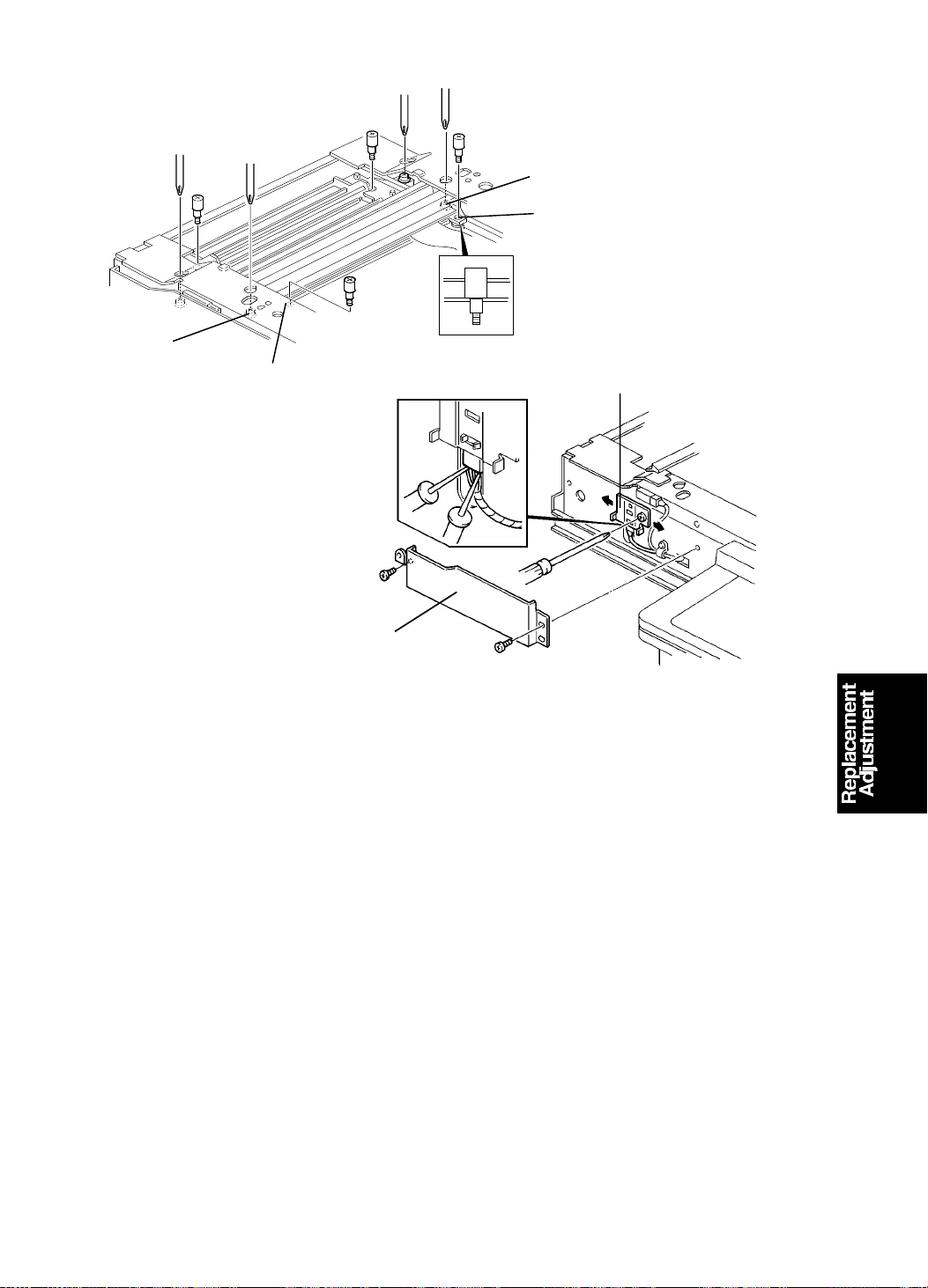
15 July 1994 SCANNER SECTION
[C]
[B]
[C]
[B]
[E]
[D]
3. Put the positioning pins in th e front and rear holes [B] of the first scan ne r.
Make sure that the positio ning pin can be set in the holes smoothly.
4. If the pins did not fit smo ot hly, adjust the position of the first scan ne r wit h
the screws [C].
5. Check and adjust the posit ion of th e second scanner using the same
procedure as in steps 3 and 4.
6. Slide the scanner unit and remove th e sensor cover [D] (2 screws).
7. Connect the probes of the multime te r to th e sensor’s connector.
CN1: +5V
CN2: GND
CN3: Scanner H.P (Signal)
8. Slide the sensor bracke t [E ] an d tighten the bracket when th e sensor
output goes to low (5 V to 0 V).
9. Check the optics adjustments an d ad just the m if nece ssary
(see section 3).
5-3
Page 86

[C]
Fig. B
[F]
SCANNER SECTION 15 July 1994
2.2 FLUORESCENT LAMP
[A]
[B]
[D]
[E]
Fig. A
1. Remove the exposure glass [A] (2 screws).
2. Remove the lamp cover [B] (2 screws).
3. Disconnect the lamp heater harness [C].
4. Remove the fluorescent lamp [D].
5. Remove the lamp heater [E].
NOTE: When you reinstall the lamp heater, make sure of the following items.
* The edge of the heater should be in the same positio n as th e lamp
bias terminal as shown in figure A.
* The maker name [F] of the lamp shou ld be covered with the heater
as shown in figure B.
5-4
Page 87
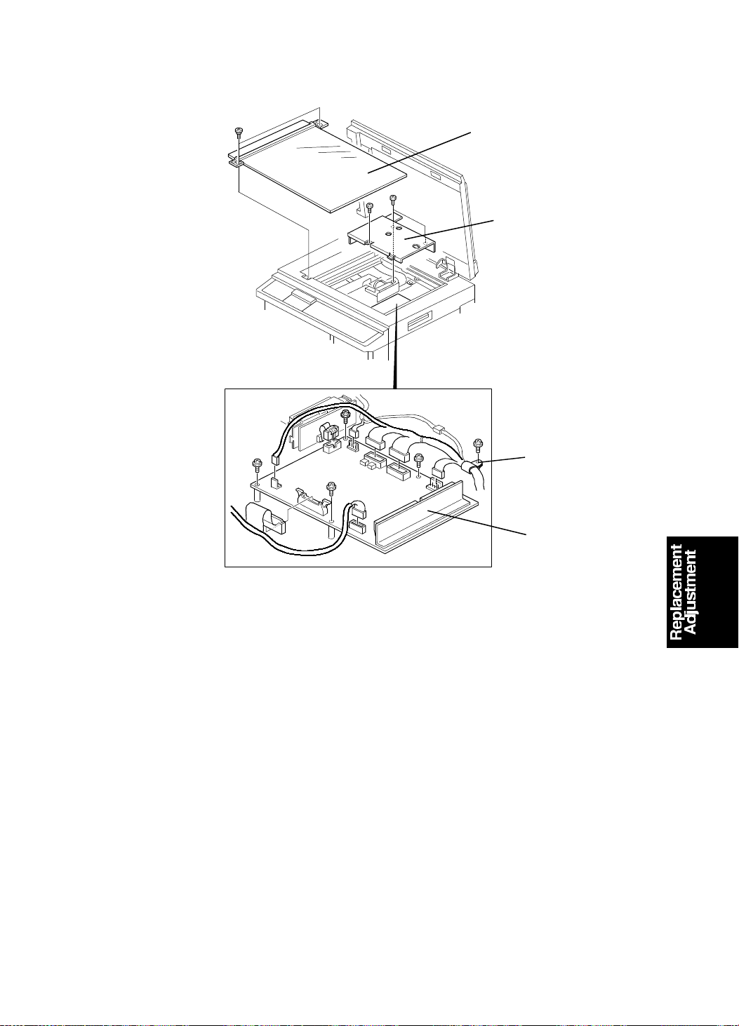
[A]
15 July 1994 SCANNER SECTION
2.3 A/D CONVERSION PCB
[B]
[C]
[D]
1. Remove the exposure glass [A] (2 screws).
2. Remove the lens block cover [B] (3 screws).
3. Remove the harness clamp [C] (1 screw).
4. Remove the A/D conversion PCB [D] (4 screws, 7 connectors).
5-5
Page 88
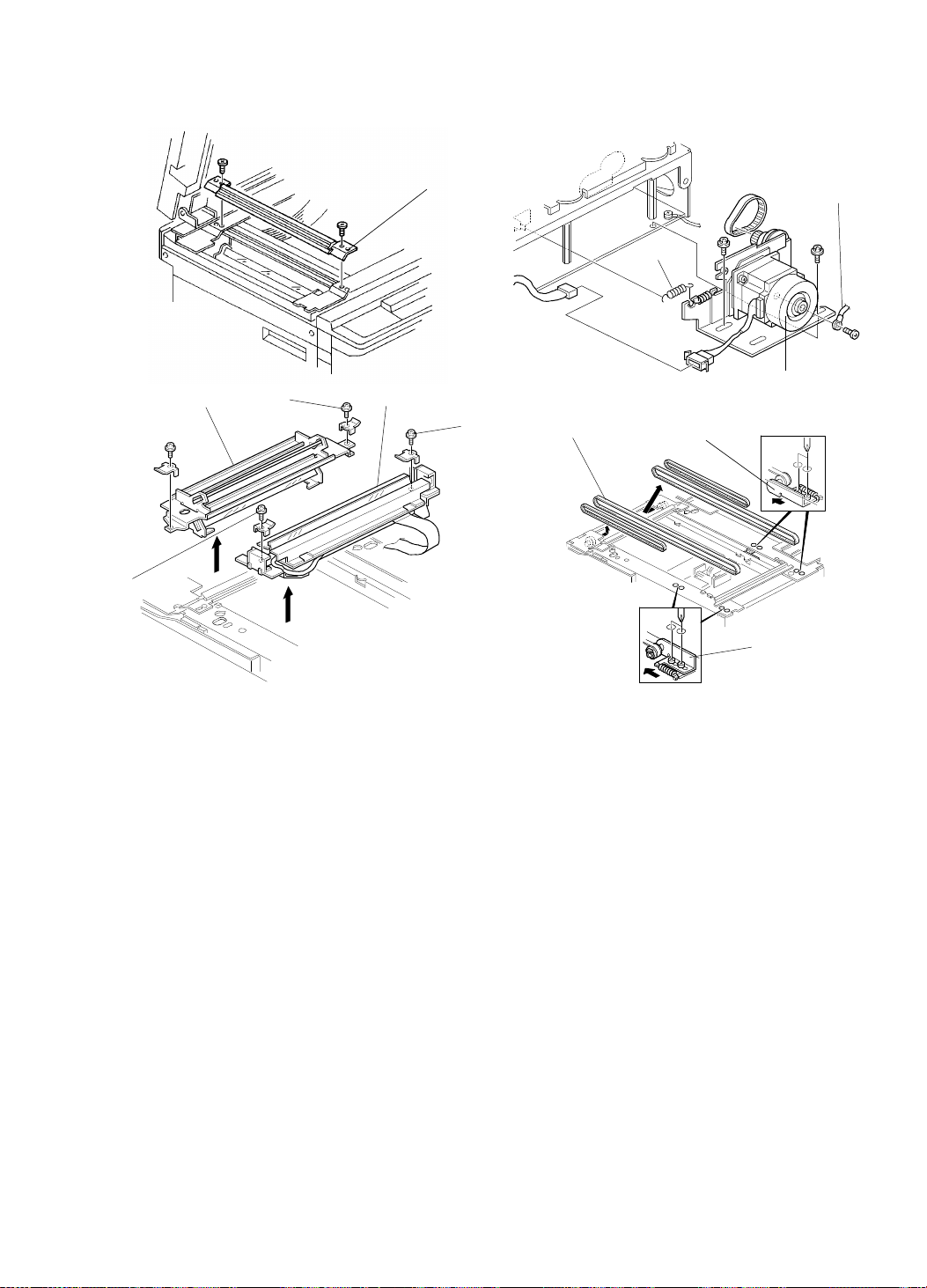
SCANNER SECTION 15 July 1994
2.4 SCANNER TIMING BELTS
[E]
[G]
[E]
[F]
[A]
[E]
[I]
[B]
[C]
[D]
[H]
[H]
1. Remove the exposure glass (see section 1-1).
2. Remove the upper cover (see section 1-1).
3. Remove the exit guide [A] (2 screws).
4. Remove the upper rear cover (see section 1-1).
5. Remove the grounding wire [B] (1 screw).
6. Remove the spring [C].
7. Remove the scanner motor assembly [D] (2 screws, 1 connector, 1 timing
belt).
8. Loosen the screws [E] securing both the 1st scanner [F] an d 2n d scan ne r
[G]. Then, take out these scanners.
9. Loosen the screws securing the belt tension bracket s [H].
10. Remove the timing belts [I].
NOTE: After replacing the scanners, the scanner positio n adjustment must
be performed (see section 2-1 ).
5-6
Page 89

15 July 1994 OPTICS SECTION
3. OPTICS SECTION
3.1 OVERVIEW
The method of optics adjustment is similar to the C210 model.
Necessary Tools
1) Facsimile Test Chart R-21 (99992131)
2) Resolution Chart (A0129110)
3) Oscilloscope
Oscilloscope Test Pin
CH1 TP603 (SIGNAL)
CH1 TP604 (OFFSET)
CH2 TP602 (TRIG)
GND TP601 (GND-A)
[A]
3.2 PREPARATION FOR ADJUSTMENT
1. Remove the upper cover (see section 1-1).
2. Remove the lens block cover.
3. Connect the terminals of the oscilloscope to the above mentioned test
pins on the A/D conversion board.
4. Turn on the main switch and access the I/O Check Mo de (SP-131).
5. Enter 21 with the number keys, then press the Print St art key t o tu rn on
the fluorescent lamp.
NOTE: Before adjusting, leave the flu orescent lamp on for 5 minutes to
stabilize the light intensity.
6. Remove the screws [A] the n ta ke of f the exposure glass, rotat e it 90
degrees, and position it as shown above .
5-7
Page 90
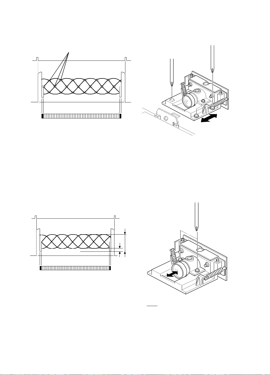
OPTICS SECTION 15 July 1994
3.3 ADJUSTING THE REDUCTION RATI O (MOIRE
ADJUSTMENT)
[A]
Position the resolution chart so that the area conce rning 200 dpi on the test
chart can be read.
Adjust the lens block position so that there are fewer than 30 cross points [A].
3.4 ADJUSTING THE FOCUS (MTF ADJUS TMENT)
a
b
Position the resolution chart so that the area conce rning 200 dpi on the test
chart can be read. Adjusting the lens po sitio n until th e wave fo rm’s
dimensions are as shown above.
a−b
x100 ≥ 60%
a+b
5-8
Page 91
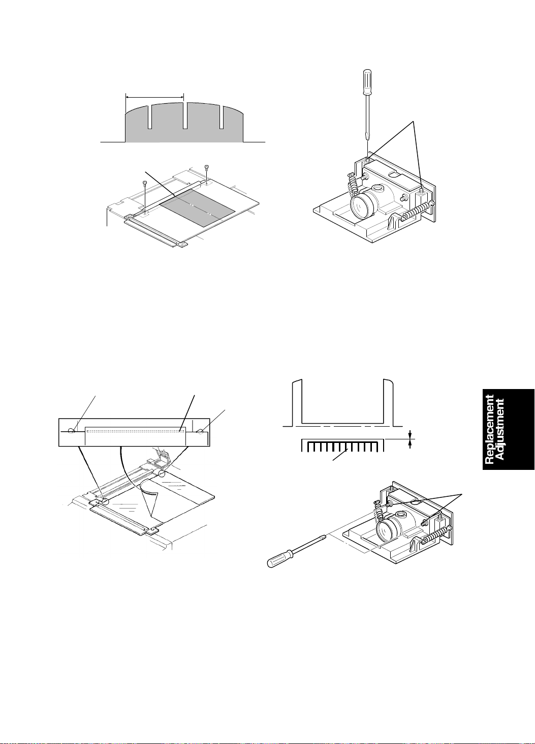
15 July 1994 OPTICS SECTION
3.5 ADJUSTING THE READI NG S TART POSITION IN THE
MAIN SCAN DIRECTION
1412.2 ± 4.6 µs
[B]
[A]
Position the test chart so that the center line, located at the leading edge of
the test chart, is posit ion ed at th e center mark [A] on the exit guid e. Th en
scan the test char t.
Adjust the CCD board position by tu rning the screws [B] until waveform is as
shown in the top diagram.
3.6 ADJUSTING THE SCAN LI NE P OSITION
[A]
Position the exposure glass so that the edge of the glass is placed across the
center of the holes [A] and place the black line of the test chart just at the
edge of the glass as shown in the above diagram.
Adjust the CCD board position by turnin g the screws [B ] so th at the shape of
the wave is similar to that shown in the above dia gra m.
Black line
[A]
1 mm
Black Line
Test Chart R21
[B]
5-9
Page 92
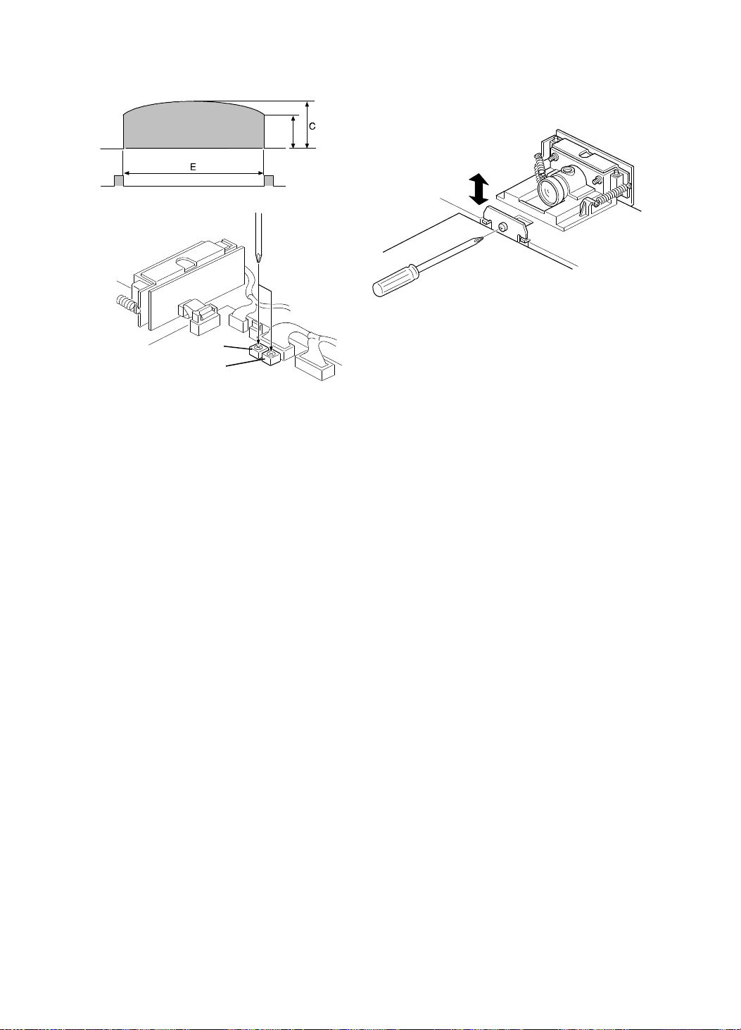
3.7 ADJUSTING THE SHADING P LATE
VR601
VR602
D> 0.7C C< 1.0V E< 3 ms
* The middle of the waveform should be hig he r tha n the ends.
Position the resolution chart so that the white area can be re ad, then turn
VR601 counterclockwise until it stops (maximu m white level). Adjust the
shading plate position so that the wave is sh aped as shown above.
3.8 ADJUSTING THE WHITE LEV EL AND BLACK LE VEL
Adjust VR601 on the A/ D conversion board so that the maximum level is 3.4
± 0.1V.
Check the standard black level at TP 604. It should be the same as t hat of
the white level. If not, adjust the standard black level b y turning VR602.
NOTE: When adjusting the standard black level, the GND level of CH1 and
CH2 should be the same.
Page 93

[E]
[E]
15 July 1994 MASTER FEED SECTION
4. MASTER FEED SECTION
4.1 ADJUSTING THE THERMAL HEAD POS ITI ON
This adjustment is only for the C218 model.
Purpose: To correct the skewed image on the ma ste r in the plat en mode.
Adjustment standard: Th ere is no skewed image appea ring on th e mast er.
[C]
[D]
[B]
1. Make a copy in the platen mo de and check that the image is without any
skew.
[E]
Skewed image
Thermal head pin rotation
[A]
2. If the image is skewed, perfo rm the follo wing steps.
2-1. Take out the master roll.
2-2. Remove the cover [A] (2 screws).
2-3. Remove thermal head cover [B] (2 screws).
2-4. Remove the platen roller [C].
2-5. Remove the thermal head [D] (2 screws, 3 connectors).
2-6. Loosen the set screw in each therma l hea d pin [E] .
2-7. Turn the pins in the opposite dire ctio n to each other at the same time
by the same amount (0.3 mm/unit on the scale).
2-8. Tighten the set screws, then check the image.
5-11
Page 94

MASTER FEED SECTION 15 July 1994
4.2 THERMAL HEAD
[C]
[B]
[E]
[G]
[H]
1. Slide the scanner unit to the left .
[A]
[D]
[E]
[F]
[F]
2. Remove the master roll.
3. Remove the thermal head cover [A] (2 screws).
4. Remove the gear cover [B] (1 screw).
5. Remove the platen roller cover [ C] (2 screws).
6. Remove the platen roller [D] (lo ose n 2 screws [E ]).
7. Remove the thermal head [F] (2 screws, 3 connectors).
NOTE
• Make sure the thermal guide plat e [G ] is p osit ioned above the
lower cutter unit guide plate [H].
• After replacing the thermal head, perform the thermal head voltage
adjustment (see section 4-1 of th e C21 0 manual).
5-12
Page 95

15 July 1994 MASTER FEED SECTION
4.3 OTHERS
NOTE: The purposes of the following items are identical to those of the C210
machines. However the spe cifications and or procedures f or th ose
items are different.
• ADJUSTING THE MASTER EJECT SENSOR
The voltage of the sen sor can be checked by SP mode No. 137 .
• ADJUSTING THE PAPER FEED ROLLER PRESSURE: C219 only
Adjust the paper feed roller pressure to 250 ± 10 grams.
• ADJUSTING THE FEED TIMING OF THE SECOND FEED
ROLLER: C219 only
Turn the cam so that the angle turned when the second feed roller
sector gear starts returning coun te rclockwise is 157°.
• ADJUSTING THE PAPER TABLE HEIGHT
Adjust the distance bet wee n the lower stay and the upper face of the
table to 148. 5 ± 0.5 mm.
• ADJUSTING THE PRESSURE TIMING
Adjust the drum rotation angle whe n the pre ss ro ller begins to touch
the drum surface to 225 ± 1°.
• ADJUSTING THE PRINTING PRESSURE: C219 only
[B]
[A]
Adjust the clearance [A] to 8 ± 0.5 mm b y turning the adjusting bolt [B ].
• ADJUSTING THE DRUM MASTER DETECTION SENSOR
The voltage of the sen sor can be checked by SP mode No. 138 .
• ADJUSTING THE FIRST PAPER EXIT SENSOR: C218 only
The output voltage of the se nso r shou ld be 0.9 ∼ 1.0 V. The voltage
can be checked by SP mode No. 135 for both models.
5-13
Page 96
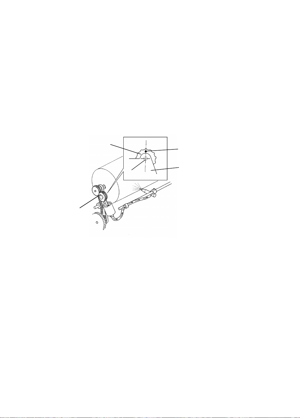
MASTER FEED SECTION 15 July 1994
• ADJUSTING THE SECOND PAPER EXIT SENSOR
The voltage of the sen sor can be checked by SP mode No. 136 .
• ADJUSTING THE CLEARANCE OF THE EXIT PAWL
Adjust the exit pawl clearance so that th e distance between the exit
pawl and the drum is between 0.6 ∼ 0.9 mm f or th e C218 machine
and 0.3 ~ 0.7 mm for the C219 ma chin e.
• ADJUSTING THE PAPER EXIT PAWL AIR PUMP
[C218]
Adjust the pump piston position so that it is at the upper dead point
when the drum has rotated 341 ± 3 degre es .
[C219]
[B]
[A]
[D]
[C]
[B]
Reposition the mark [A] on the pump drive gear [B] to be right over the
gear shaft [C] when the dru m is at the home position.
• ADJUSTING THE PRINTING SPEED: C219 only
Adjust the printing speed in the maximum printing speed mod e to
130 ± 5 rpm by turning VR105 on the main PCB.
5-14
Page 97

15 July 1994 IMAGE ADJUSTMENT
5. IMAGE ADJUSTMENT
5.1 SUB SCAN MAGNIFICATI ON ADJ USTME N T
Purpose: To correct the sub scan magnification.
Adjustment Standard: 100 ± 0.5% in the full size mode.
1. Using a test chart, make a print
using the platen cover mode.
2. Check that the sub scan
magnification is within the
specification.
3. If it is out of specification, adju st the
sub scan magnificatio n usin g SP
No.30.
SP No. 30
5.2 IMAGE CENTER ADJUSTMENT (Side to Side)
Purpose: To correct th e cen ter position of the print imag e.
Adjustment Stand ard: Less than 1 mm
1. Using a test chart, make a print using the platen cove r mo de .
NOTE: The center line located at the lea ding edge of the test cha rt
should be set at the cen ter mark on the left scale .
2. Compare the original and the print ima ge, th en conf irm tha t the dif fe ren ce
between them is within 1mm.
3. If the difference is too great, adjust the image center using SP No. 39.
5-15
Page 98

IMAGE ADJUSTMENT 15 July 1994
5.3 SCANNER LEADING EDGE REG ISTRATI O N ADJUS TMENT
Purpose: To adjust the scanner start position accord ing to th e customer’s
request.
Standard Position : Scanning starts at 8 mm after th e leading edge.
NOTE: When performing this adjustment, set the print spe ed and the image
position to the standard positions.
1. Using a test chart, make a print
using the platen mode.
2. Check the scanner start posit ion
and adjust the scan ne r le ad ing
edge registration usin g SP No. 33.
5-16
Page 99
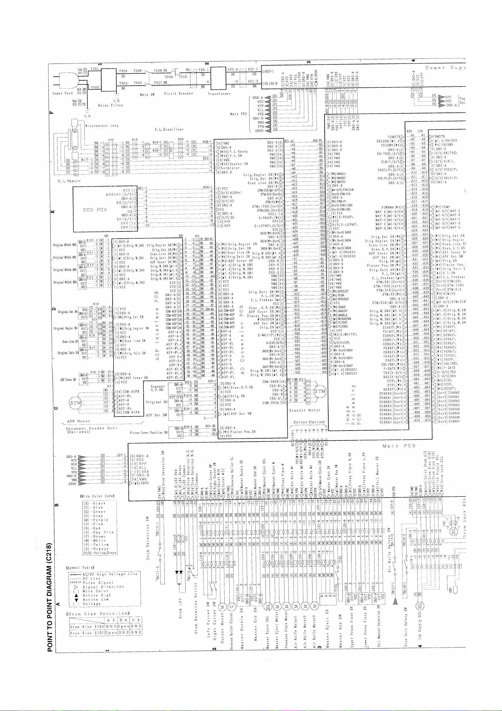
Page 100

 Loading...