

Page 1
INTRODUCTION
INTRODUCTION
This manual contains detailed instructions on the operation and maintenance of this machine. To get the maximum versatility from this machine, all
operators should carefully read and follow the instructions in this manual.
Please keep this manual in a handy place near the machine.
Please read the next section before using this machine. It contains important information related to USER SAFETY and PREV ENTING EQUIPMENT
PROBLEMS.
SAFETY INFORMATION
When using your machine, the following safety precautions should always
be followed.
Safety During Operation
In this manual, the following important symbols are us ed:
$
WARNING:Ignoring this warning could cause serious injury
or even death.
$
CAUTION: Ignoring this caution could cause injury or
damage to property.
Examples Of Indications
$
Symbols $ means a situation that requires you take care.
B
Do NOT carry out the operation represented by the symbol >.
This example means "Do not take apart".
C
Symbols ● means you MUST perform this operation.
This example means "You must remove the wall plug".
i
Page 2

SAFETY INFORMATION
WARNINGS:
$
•• Only connect the machine to the power source described on
the inside front cover of this manual. Avoid multi-wiring as
>
>
B
it could cause an electric shock or a fire.
•• Avoid using an extension cord. Make sure the wall outlet is
near the machine and freely accessible so that in event of an
emergency it can be unplugged easily.
•• Do not damage, break or make any modifications to the
power cord. Do not place heavy objects on it, pull it hard or
bend it more than necessary. These actions could cause an
electric shock or fire.
•• Do not remove any covers or screws other than those
specified in this manual. Some parts of the machine are at a
high voltage and could give you an electric shock. When the
machine needs to be checked, adjusted or repaired, contact
your service representative.
•• Do not take apart or attempt any modifications to this
machine. There is a risk of fire, electric shock, explosion or
loss of sight.
C
>
C
ii
•• If the machine looks damaged or breaks down, smoke is
coming out, there is a strange smell or anything looks
unusual, immediately turn off the main power switch then
unplug the power code from the wall. Do not continue using
the machine in this condition. Contact your service representative.
•• Do not put any metal objects or containers holding water
(e.g. vases, flowerpots, glasses) on the machine. If the
contents fall inside the machine a fire or electric shock could
occur.
•• If any metal, liquid or foreign matter falls into the machine,
turn off the main switch and unplug the main power cord.
Contact your service representative. Do not keep using the
machine with a fault or defect.
Page 3

>
CAUTIONS:
$
C
E
>
C
SAFETY INFORMATION
•• Do not plug or unplug the power cord with wet hands or an
electric shock might occur.
•• When you move the machine, unplug the power cord from
the wall outlet to avoid fire or electric shock.
•• When you pull out the plug from the socket, grip the plug to
avoid damaging the cord and causing fire or electric shock.
•• Keep the machine away from humidity and dust. A fire or
an electric shock might occur.
•• Do not place the machine on an unstable or tilted surface.
If it topples over it could cause injury.
•• When the machine will not be used for a long time, unplug
the power cord.
@
$
•• If you use this machine in a confined space, make sure there
is a continuous air turnover.
•• This machine has been tested for safety using this supplier’s
parts and consumable. We recommend you only use these
specified supplies.
iii
Page 4
GUIDE TO COMPONENTS
Machine Exterior
GUIDE TO COMPONENTS
10
1
2
3
4
5
6
7
8
9
1
Page 5

GUIDE TO COMPONENTS
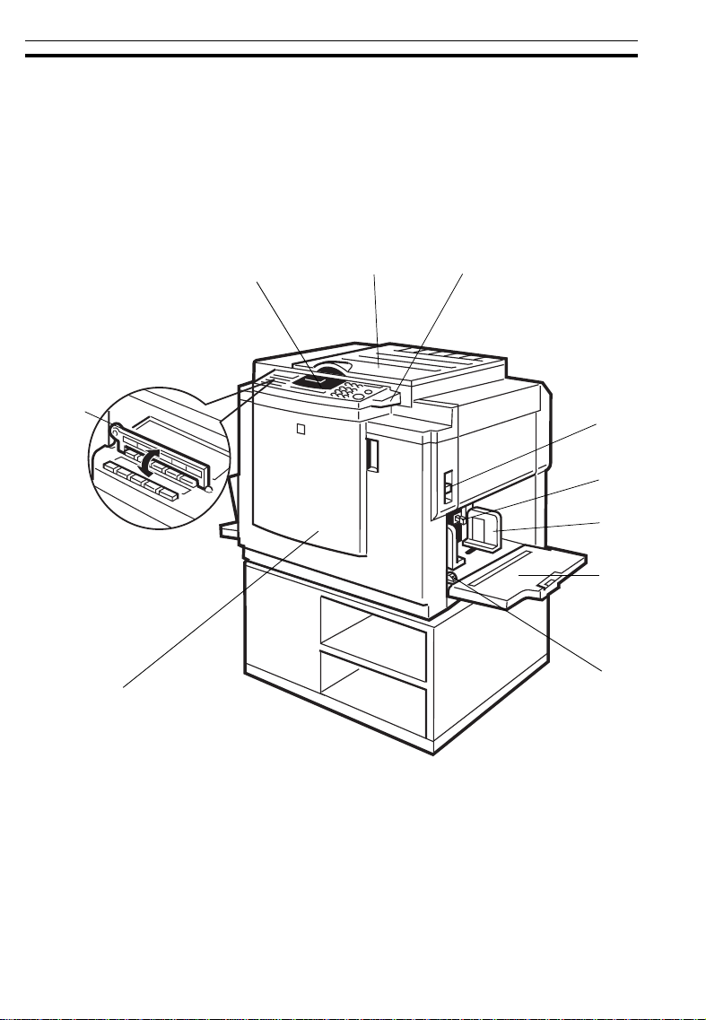
1. Operation panel
2. Platen cover
3. Original table
release lever
4. Feed roller
pressure lever
5. Separat ion rol ler
pressure lever
6. Paper feed side
plates
7. Paper feed table
8. Side plate fine
adjusting dial
9. Front cover
Operator controls and indicators are located
here. ☛ See pages 5 ~ 7.
Lower this cover over an original before printing.
Use to open the original table unit when installing
the master.
Use to adjust the contact pressure of the paper
feed roller according to paper thickness.
Use to adjust the separation roller pressure to
prevent double feed.
Use to prevent paper skew.
Set paper on this table for printing.
Use to shift the paper feed table sideways.
Open to access to the inside of the machine.
10. Plate
Flip over when you use One Touch Class function. ☛ See page 47.
2
Page 6
GUIDE TO COMPONENTS
Machine Interior
15
14
13
12
1
23
4
5
6
7
8
11
3
10
9
Page 7

GUIDE TO COMPONENTS
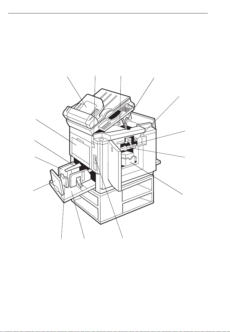
1. Document feeder
(Option)
2. Master eject unit
open button
3. Master cut button
4. Pressure release
lever
5. Drum rotation
button
6. Drum unit lock
lever
7. Drum unit
8. Ink holder
9. Main switch
10. Paper delivery table
11. Small size paper
delivery end plate
12. Paper delivery end
plate
13. Paper delivery side
plate
14. Wing guides
Original inserted into the document feeder are individually and automatically fed onto and removed from the exposure glass. ☛ See page 82.
Press to remove misfed paper or a misfed master.
Press this button to cut the master leading edge
after installing a new master roll.
Use to install the master roll.
Press to rotate the drum unit.
Lift to unlock and pull out the drum unit.
The master is wrapped around this unit.
Set the ink cartridge in this holder.
Use to turn the power on or off.
Completed prints are delivered here.
Use to align the leading edge of prints that are
A4, 8
Use to align the leading edge of prints larger
than A4, 8
Use to align the prints on the paper delivery table.
When printing on thin or small size paper, lift
these guides. ☛ See page 15.
" x 11" or smaller.
1/2
" x 11".
1/2
15. Master eject
Open when removing the master eject box.
container cover
❐
Other options: Color Drums (r ed, blue, gre en, brown, yellow, pu rple, navy,
maroon, orange and teal)
Tape Dispense r
Key Counter
Cabinet
4
Page 8
GUIDE TO COMPONENTS
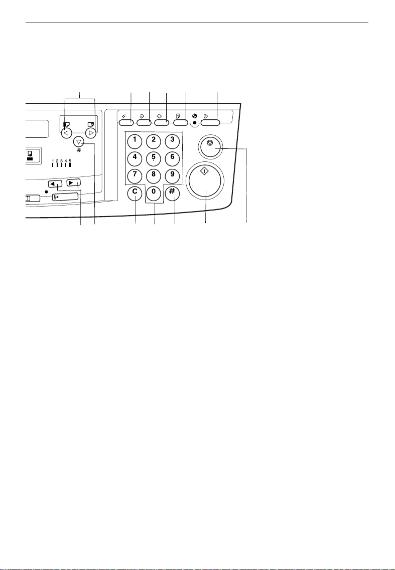
Operation Panel
Keys
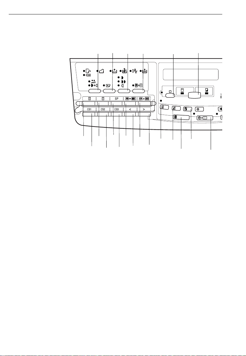
1. Economy/Tint key
☛
See pages 42 ~ 44.
2. Skip Feed key
☛
See page 71.
3. Image Density key
☛
See page 23.
20
6
19
21
1
2
3
4
7
12
9
8
13
10 11
14
10. Edge Erase key
11. Edge Erase/C enter Eras e key
12. 13. 14. CS mode ke ys
16
15
☛
See page 34.
☛
See page 31.
☛
See pages 97 ~ 101.
17
5
18
4. Paste Shadow Erase key
☛
See page 36.
5. Auto Cycle key
☛
See page 45.
6. Master Making/Print key
Press to select Master Making or
Print mode.
7. Security key
☛
See page 79.
8. Quality Start key
☛
See page 80.
9. SP mode key
☛
See page 94.
5
15. 16. Scroll key s
Press to select size and direction
of paper or original in Edge
Erase/Center Erase and Edge
Erase function.
Press to select the mode in Service Program mode.
17. Type of Origina l key
☛
See page 40.
18. Reduce key
☛
See page 27.
19. Enlarge key
☛
See page 29.
Page 9
GUIDE TO COMPONENTS
22
28
29
23
30
20. Full Size key
Press to ma ke full size p rints.
21. Combine 2 Originals key
☛
See page 63.
22. Image Positi on keys
☛
See page 21.
23. Reset key
Press to reset the error indicators.
24. Program Clas s key
☛
See page 47.
25. Program key
☛
See page 73.
26. Proof key
Press to ma ke proo f print s.
24 25
31
32
27
26
33
28. Speed keys
29. Lower key
30. Clear key
31. Number keys
32. Enter key
33. Start key
34
☛
See page 24.
Press to lower the paper feed table.
Press to change the number set.
Press to enter the number of
prints and data.
Press to input da ta into memo ry.
Press to start making of a master
or printing.
27. Clear Modes ke y
Press to canc el all previously entered settings .
34. Stop key
Press to st op the machine operation.
6
Page 10
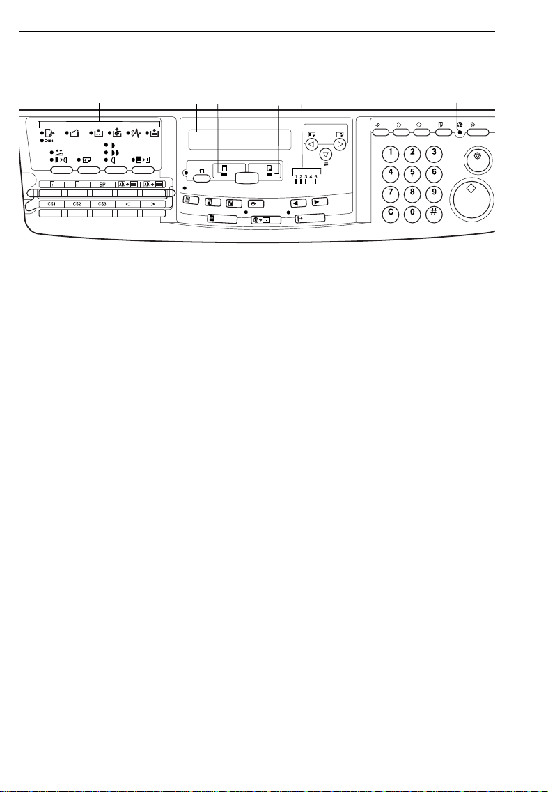
GUIDE TO COMPONENTS
Indicators
1. Error indicators
These indicators are lit when a
non-standard condition occurs
within the machine. ☛ See page
128.
2. Guidance Display
Press to stop th e machine operation.
3. Master Maki ng indic ator
This indicator is lit when Master
Making mode is selected.
1
3
2
4
5
4. Print indicator
This indicator is lit when Print
mode is sele cted.
5. Speed indicator s
These indicat ors show the printing
speed that is selected. ☛ See
page 24.
6. Color Drum indicator
This indicator is lit when the optional color drum unit is set.
See page 88.
6
☛
7
Page 11

INSTALLATION REQUIREMENTS
INSTALLATION REQUIREMENTS
The machine’s location should be carefully chosen because environmental
conditions can affect its performance.
Optimum Environmental Conditions
❐
Temperature: 10 - 30°C, 50 - 86°F
❐
Humidity: Main frame: 20 - 90 % RH
Document feeder (option): 20 - 70 % RH
❐
A strong and level base (A s turdy d esk an d cabi net etc. ).
❐
The machine must be level withi n 5 mm (13/64") both front to rear and le ft to
right.
❐
Make sure to locate t his ma chine in a lar ge wel l ventil ated ro om tha t has an air
turnover of more than 30 m
Environments To Avoid
❐
Direct sunlight or strong light (more than 1500 lux).
❐
Locations dir ectly expo sed to cool ai r from an air condition er or heated air from
a heater. (Sudden temperature changes from low to high or vice versa may
cause condensation within the machine.)
❐
Dusty areas.
3
/hr/person.
Access To The Machine
❐
Place the machine near a power source, providing clearance as shown.
More than 20 cm, 8.0"
More than 60 cm,
23.7"
Machine
More than 60 cm, 23.7"
More than 60 cm, 23.7"
8
Page 12

INSTALLATION REQUIREMENTS
Power Connection
WARNING:
$
•• Only connect the machine to the power source described on the
inside front cover of this manual.
Avoid multi-wiring as it could cause an electric shock or a fire.
•• Avoid using an extension cord. Make sure the wall outlet is near
the machine and freely accessible so that in event of an emergency
it can be unplugg ed easily .
•• Do not damage, break or make any modifications to the power cord.
Do not place heavy objects on it, pull it hard or bend it more than
necessary. These actions could cause an electric shock or fire.
CAUTION:
$
•• When you move the machine, unplug the power cord from the wall
outlet to avoid fire or electric shock.
•• When you pull out the plug from the socket, grip the plug to avoid
damaging the cord and causing fire or electric shock.
❐
Make sure the pl ug is firml y inserte d in the outlet.
❐
Avoid multiwi ring.
❐
Do not pinch the power cord.
9
Page 13
OPERATION
Printing Paper
The following typ es of print paper are not recommen ded for this ma chine.
❐
• Paper smaller than 90 mm x 148 mm, 3.6" x 5.9"
• Paper larger th an 297 mm x 432 mm , 11.6" x 17.0 "
• Paper heavier than 209.3 g/m
• Paper lighter than 47.1 g/m
(However, 45 g/m
is setting 1, 2 or 3 an d the separat ion press ure levers are in the "Th ick"
position.)
• Roughly-c ut paper
• Paper of differ ent thi ckness in th e same stack
• Buckled or cur led paper
• Short gr ain pa per
• Low stiffn ess pa per
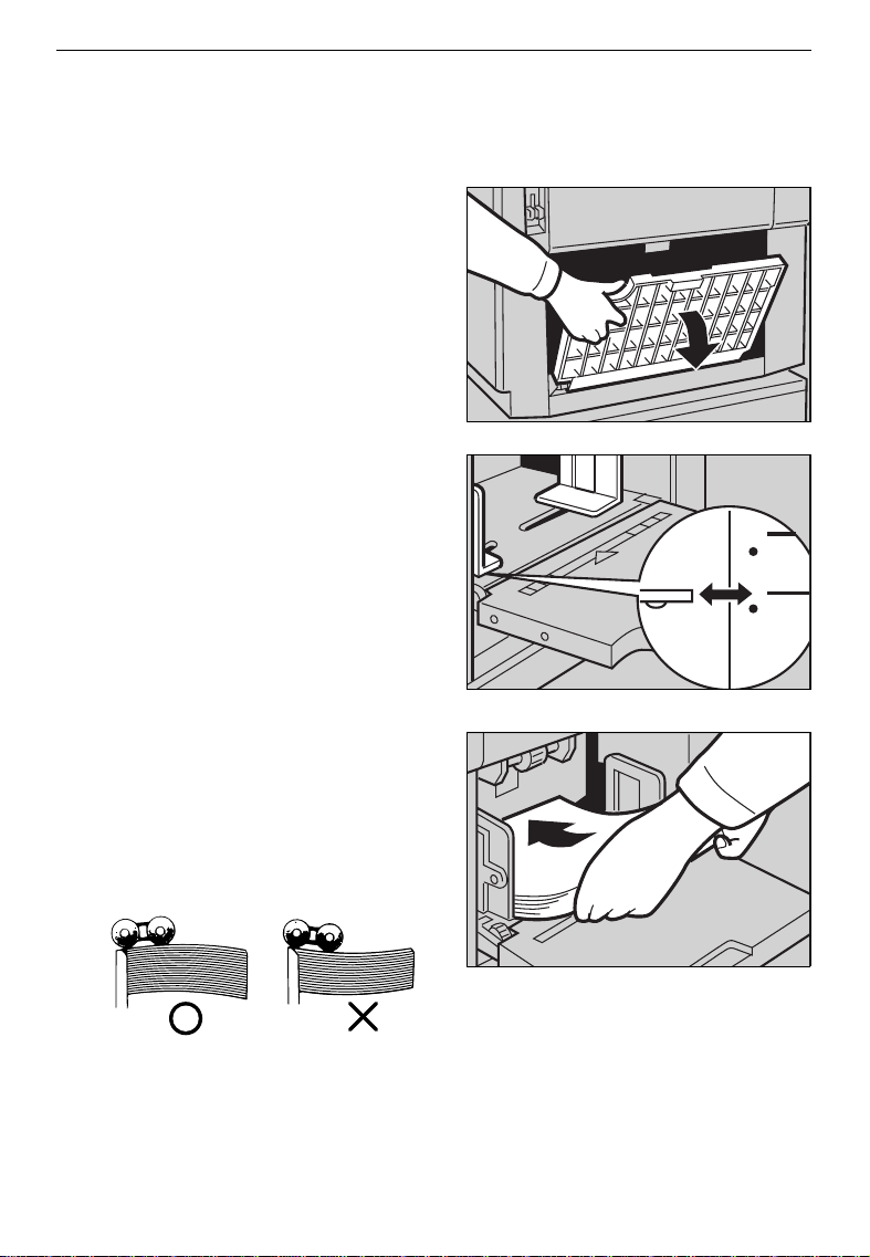
Correct curls in the paper before setting it in the machine. When you cannot
❐
correct the pa per curl, stack the paper with the curl face dow n. Otherwise the
paper migh t wrap around the d rum or stain s migh t appe ar.
Store paper wh ere it will not curl or absorb moisture. Use paper soon after it is
❐
unpacked.
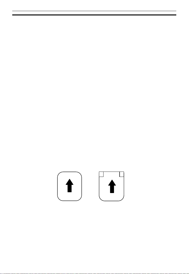
Only use paper where the leading edge has two right angle corners, as shown
❐
below.
2
, 55.6 lb
2
, 12.5 lb
2
, 11.9 lb pa per m ay be used when t he pr inting speed
OPERATION
Not OK
OK
10
Page 14
OPERATION
Originals
Originals tha t can be set on the ex posure gl ass are as fo llows:
❐
• Maximu m size: 257 x 364 mm, 10.2" x 14.4 "
• Maximu m total thickn ess: 30 mm, 1.1"
• Maximu m total weigh t: 5 kg, 11.0 lb
If you use paste-up originals, make sure the pasted parts hold firmly to the
❐
base sheet and press the Paste Shadow Erase key. If the thickness of the
paste-up orig inal is more t han 0.1 mm and the sp ace between the pas ted parts
is less than 2 mm, 2/25", a shadow might appe ar on the prin ts.
If you use originals tha t have bold lett ers or solid images at the leading edges,
❐
you might get pri nts with dirty edg es. In this case, inse rt the widest margi n first,
or raise the printing speed.
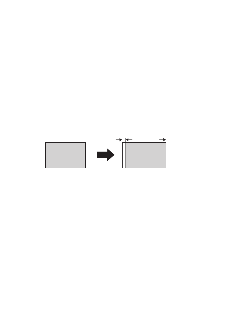
The first 5 mm, 0.2" of the leading edge cannot be printed. Make sure the
❐
leading edge margin is at least 5 mm, 0.2".
Original
5 mm, 0.2"
Print
11
Page 15
Preparation For Printing
Carefully open the paper feed ta-
1
ble.
❐
Keep hold the paper feed table until it
stops.
Adjust the side plates to match
2
the paper size.
OPERATION
Place the paper on the paper
3
feed table.
❐
Correct the paper curl before setting
the paper. If you cannot do so, stack
the paper with the curl face down as
shown.
12
Page 16
OPERATION
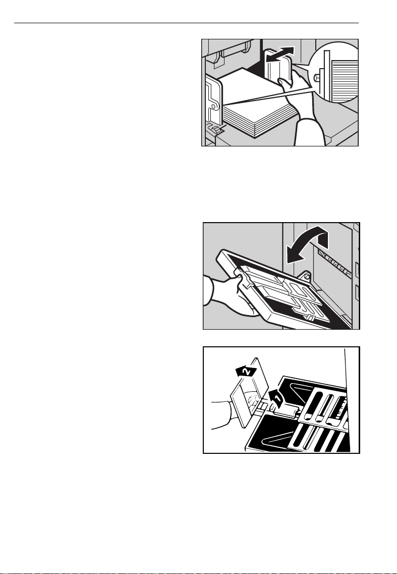
Make sure that the paper feed
4
side plates contact the paper
lightly.
Setting up the paper delivery table
Lift up the paper delivery table a
5
little and then open it.
Lift the paper delivery end plate
6
and move it to match the print
paper size.
13
Page 17
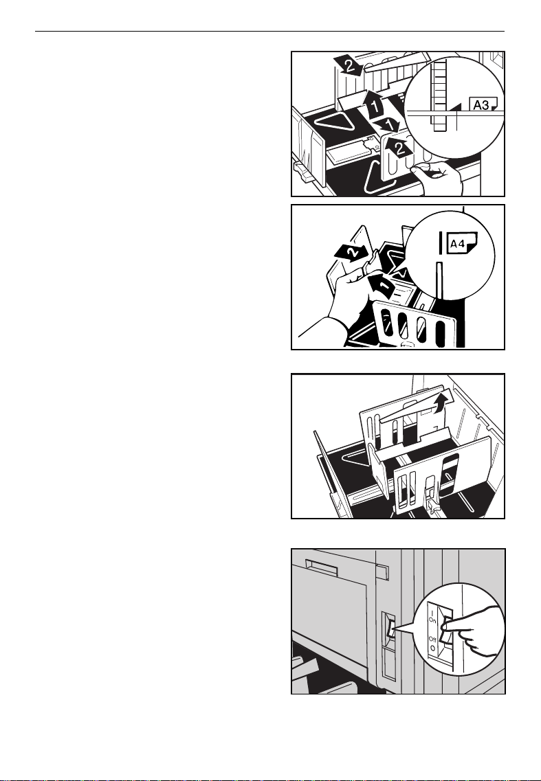
Lift the paper delivery side plates
7
and adjust them to the paper
size.
OPERATION
1
If you want to use A4, 8
8
or smaller paper, lift the small
size paper delivery end plate and
move it to match the print paper
size.
❐
When you use B4, 8
paper, you do not need to lift the
small size paper delivery end plate.
If necessary, lift the left and right
9
wing guides.
❐
If you find paper is not delivered
properly wh en printing on thin paper,
make sure the win g guides ar e up.
❐
When printing on paper thicker than
81.4 g/m
wing guides.
Turn on the main switch.
2
, 21.6 lb, do not lift up the
" x 14" size
1/2
A
1/2
" x 11"
14
Page 18

OPERATION
Setting the small size end plate prop
If A4, 8
properly, set the small size end plate prop to the small size paper delivery
end plate.
1
2
" x 11" or smaller paper is not delivered to the paper delivery table
1/2
Set the small size end plate prop
to the small size paper delivery
end plate as shown in the illustration.
Slide the prop until it locks in position.
Adjust the main frame side of the
3
prop to match the paper size.
15
Page 19
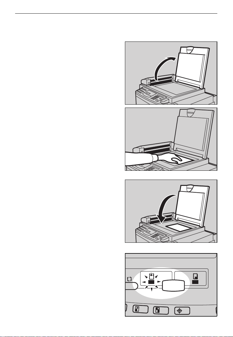
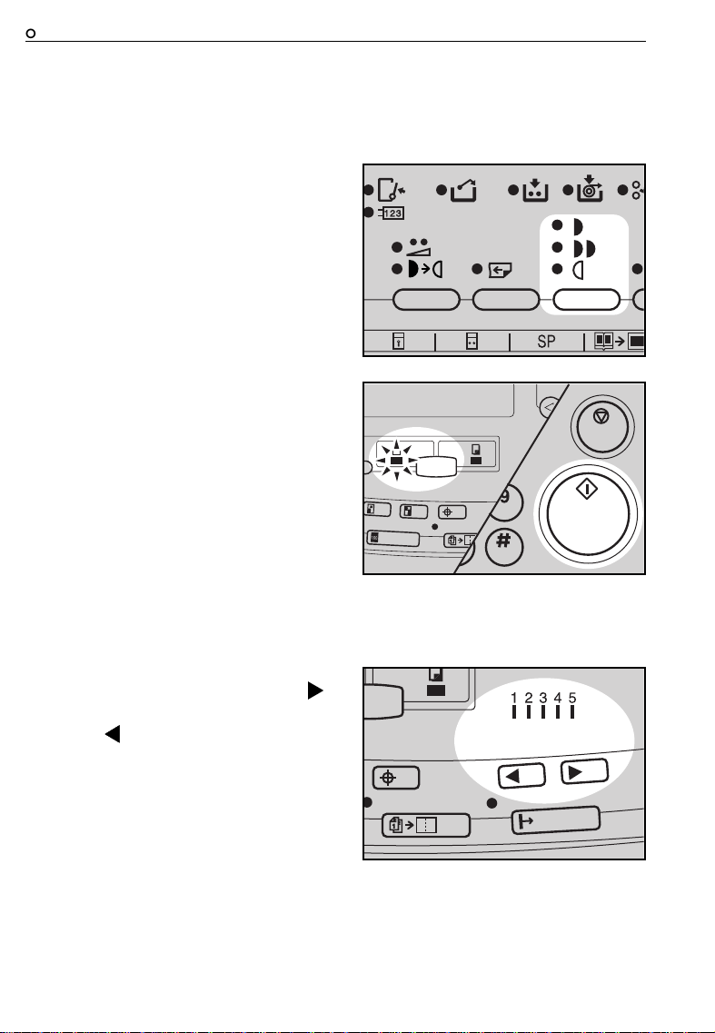
Standard Printing
Open the platen cover.
1
Place the original face down on
2
the exposure glass. The original
should be centered according to
the size marks on the right scale.
OPERATION
Lower the platen cover.
3
Make sure the
4
indicator is lit. If not, press the
Master Making/Print
lect the Master Making mode.
Master Making
key and se-
16
Page 20
OPERATION
Press the
Start
key.
5
❐
A trial print is delivered to the paper
delivery tabl e.
Press the
6
the image density and the image
position of the proof print.
❐
If the image position is not correct,
adjust it using the Image Position
keys or the fine adjustment dial.
(☛ See pages 21 and 2 2.)
❐
If the imag e density is slightly da rk or
light, adjust the image density by
pressing the Speed keys. (☛ See
page 24.)
Enter the number of prints re-
7
quired using the
❐
Up to 9999 prints can be entered at
one time.
❐
To change the number entered,
press the Clear key and then enter
the new number .
Proof
key and check
Number
keys.
Make sure the
8
lit and then press the
❐
After printing is completed, the same
number of prints is automatically set
for the next job.
❐
If you want to stop th e machine during a print r un, p ress th e Stop key.
17
Print
indicator is
Start
key.
Page 21

Remove the prints from the paper
9
delivery table.
❐
To clear all the modes you have selected, press the Clear Modes key.
OPERATION
18
Page 22
OPERATION
Restoring Paper Feed And Paper Delivery Tables
Remove the paper from the pa-
1
per feed table.
❐
The paper feed table will lower.
Turn off the main switch.
2
Close the paper feed table.
3
Push the small size paper deliv-
4
ery plate to the left, then lower it,
if necessary.
19
Page 23

Return the left and right wing
5
guides to their original positions,
if necessary.
Move the side plates to the sides,
6
then lower them.
❐
Make sure tha t the side plat es do not
touch the small size paper delivery
end plate.
Move the end plate until the plate
7
handle is flush with the end of the
table.
OPERATION
Lower the end plate.
8
Close the table.
9
20
Page 24
OPERATION
Adjusting The Image Position
Shifting the image position forward or backward
Press the right or left
1
sition
key.
❐
When you shift the image forwards,
leave a margin (more than 5 mm,
0.2") at the leading edge. If there is
no margin, paper might wrap around
the drum and caus e a misfeed.
❐
The right or le ft Image Position keys
shift the image about 0.5 mm, 1/50"
each time they are pressed. When
the indicator changes, the image position shifts ab out 5 mm, 1/5" .
Press the
2
image position again.
Proof
Image Po-
key. Check the
21
Page 25
Shifting the image to the right or left
OPERATION
Turn the side plate fine adjusting
1
dial as shown in the illustrations.
❐
The image posi tion can be shifted up
to about 10 mm, 2/5" each way.
Each division on the scale is 2 mm,
0.08".
Adjust the paper delivery side
2
plates to the print paper position.
<Shifting the image to the right>
<Shifting the image to the left>
Press the
3
image position.
Proof
key. Check the
22
Page 26
OPERATION
Adjusting The Image Density
Before making a master
Select the desired image density
1
using the
Make sure that Master Making in-
2
dicator is lit and then press the
Start
Image Density
key.
key.
After making a master
Press the
1
crease the speed, press the “ % ”
key. To reduce the speed, press
the “ ” key.
❐
The faster the printing speed becomes, the light er the printin g density
is. If you want darker prints, decrease the print ing speed.
23
Speed
keys. To in-
Page 27
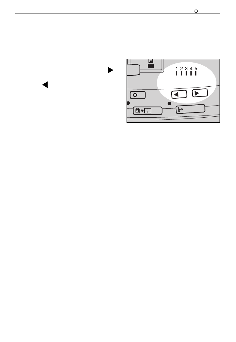
Changing The Printing Speed
OPERATION
Use the
Speed
keys to adjust the speed of the machine with the image
density and printing paper.
Press the
Speed
keys. To in-
crease the speed, press the “ % ”
key. To reduce the speed, press
the “ ” key. The printing speed
will be changed as follows:
Setting 1: 60 sheets/minute
Setting 2: 75 sheets/minute
Setting 3: 90 sheets/minute
Setting 4: 105 sheets/minute
Setting 5: 120 sheets/minute
❐
When the main switch is turned on,
Setting 3 is sel ected.
❐
The faster the printing speed becomes, the lighter th e printing density
is, and vice versa.
24
Page 28
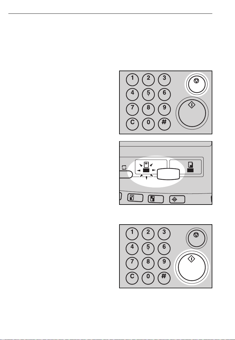
OPERATION
Stopping The Machine During A Print Run
When you want to stop the machine during a print run and print the next original
Press the
Stop
key.
1
Press the
2
key to select Master Making
mode.
Set the new original.
Master Making/Print
3
Press the
Start
key.
4
25
Page 29
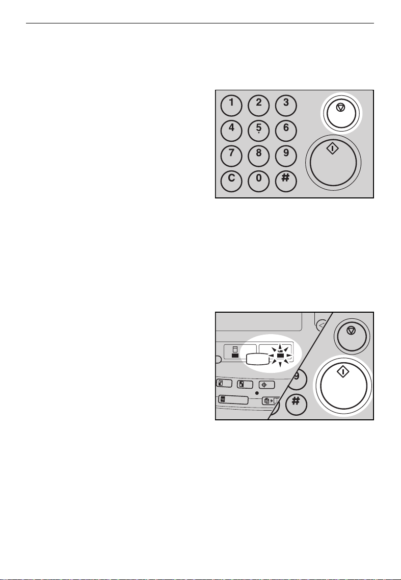
OPERATION
When you want to change the number of prints entered or check the completed prints
Press the
Stop
key.
1
Change the number of prints or
2
check the completed prints.
❐
When you change the number of
prints, you can re-enter the number
using the Number keys after press-
ing the Stop key.
Make sure that
3
lit and then press the
Print
indicator is
Start
key.
26
Page 30
OPERATION
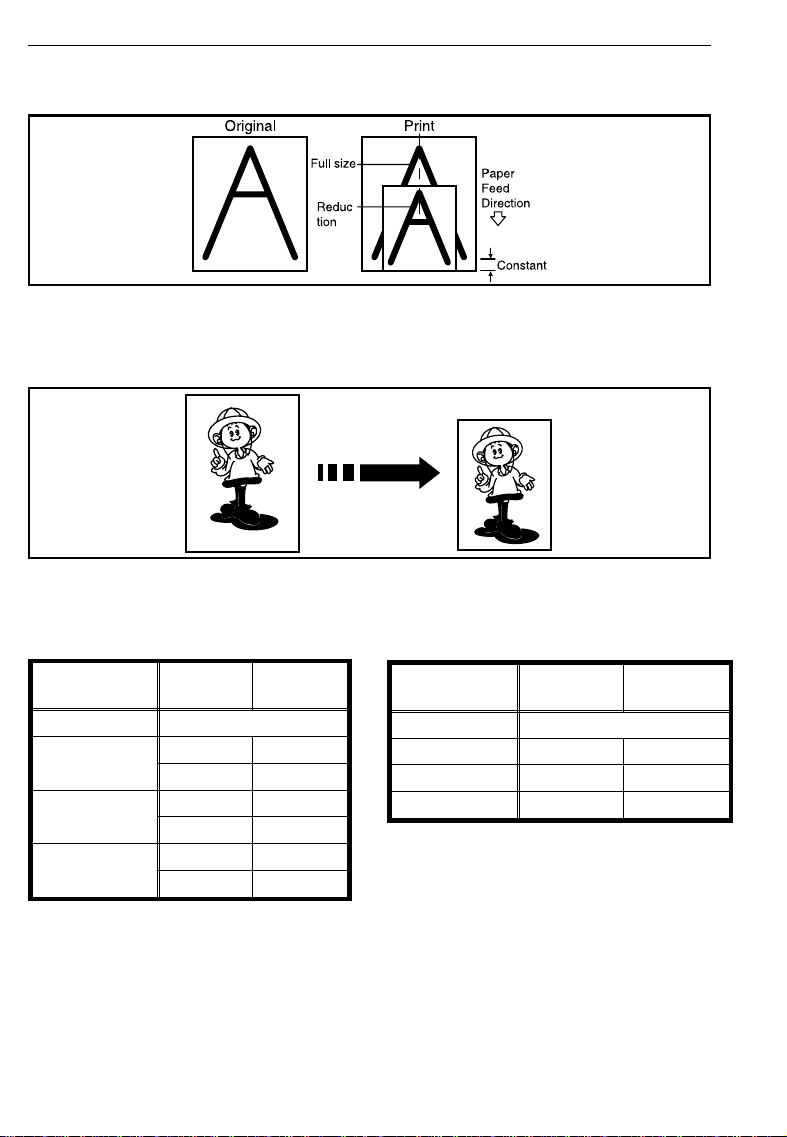
Reduction/Enlargement Printing (Reduce/Enlarge)
The center and the leading edge of the print image do not shift when a print im-
❐
age is made with th is function.
Reduction
Prints can be reduced in size by us ing the
Reduce
key.
— Metric version — — Inch version —
Reduction
Ratio
93 % *
87 %
82 %
71 %
* Select this ratio when you make prints with a lot of edge margins.
27
Original
Size
A5 B6
A4 B5
B4 A4
B5 A5
A4 A5
B4 B5
Print Size
Reduction
Ratio
Original
Size
93 % *
77 % 8
" x 14" 8
1/2
74 % 10" x 14" 8
65 % 8
" x 11" 5
1/2
Print Size
" x 11"
1/2
" x 11"
1/2
" x 8
1/2
1/2
"
Page 31

Select the desired reduction ratio
1
using the
❐
If you want to return the ratio to 100
%, press the Full Size key.
Make sure that the original and
2
the print paper are the correct
size.
Set your originals on the expo-
3
sure glass or in the optional
document feeder.
Reduce
key.
OPERATION
Make sure that
4
indicator is lit and then press the
Start
key. Check the image posi-
tion of the trial or proof print.
❐
If the image position is not correct,
adjust it using the Image Position
keys (☛ see page 21) or the side
plate fine adjust ing dial (☛ see page
22).
Enter the number of prints re-
5
quired using the
Make sure that the
6
is lit and then press the
key.
Master Making
Number
Print
keys.
indicator
Start
28
Page 32

OPERATION
Enlargement
Prints can be enlarged by using the
Enlarge
key.
— Metric version — — Inch version —
Enlargement
Ratio
141 %
122 %
115 %
Original
Size
B5 B4
A5 A4
A4 B4
A5 B5
B5 A4
B6 A5
Print Size
Enlargement
Ratio
155 % 5
129 % 5
121 % 8
Original
Size
" x 8
1/2
" x 8
1/2
" x 11" 11" x 15"
1/2
1/2
1/2
"8
"8
Print Size
1/2
1/2
" x 14"
" x 11"
29
Page 33

Select the desired enlargement
1
ratio using the
❐
If you want to return the ratio to 100
%, press the Full Size key.
Make sure that the original and
2
the print paper are the correct
size.
Set your originals on the expo-
3
sure glass or in the optional
document feeder.
Enlarge
key.
OPERATION
Make sure that
4
indicator is lit and then press the
Start
key. Check the image posi-
tion of the trial or proof print.
❐
If the image position is not correct,
adjust it using the Image Position
keys (☛ see page 21) or the side
plate fine adjust ing dial (☛ see page
22).
Enter the number of prints re-
5
quired using the
Make sure that
6
lit and then press the
Master Making
Number
Print
indicator is
Start
keys.
key.
30
Page 34

OPERATION
Erasing Center And Edge Margins
(Edge Erase/Center Erase)
When printing from thick books, or similar originals, the binding margin at
the center and the edges might appear on prints. To prevent this, follow the
steps on the next page.
As a default setting, the paper sizes and directions that can be used are as fol-
❐
lows:
Metric version: B4 ;, A4 ;, A5 :, A5;, B5 :, B5
Inch versio n: 8
If you want to use othe r size ori ginals, yo u can registe r the size us ing Serv ice
Program mode. ☛ See page 107.
The margin widt h to be erase d can be adjus ted with Serv ice Prog ram mode.
❐
☛
See page 107 .
" x 14" ;, 8
1/2
" x 11" ;, 5
1/2
1/2
" x 8
;
1/2
" ;, 5
1/2
" x 8
1/2
"
:
31
Page 35

OPERATION
Press the
1
Erase
key.
❐
To cancel this mode, press the Edge
Erase/Center Erase key again.
Press the "<" or ">" key to select
2
the paper size and direction.
When you reach the desired pa-
3
per size and direction, press the
Enter
key.
Edge Erase/Center
Set the book on the exposure
4
glass.
32
Page 36

OPERATION
Make sure that
5
indicator is lit and then press the
Start
key.
Check the image position of the
6
trial or proof print.
❐
If the image position is not correct,
adjust it using the Image Position
keys (☛ see page 21) or the side
plate fine a djusting dial (☛ see page
22).
Enter the number of prints using
7
8
Number
the
Make sure that
lit and then press the
Master Making
keys.
Print
indicator is
Start
key.
33
Page 37

OPERATION
Erasing Edge Margins (Edge Erase)
If you want to erase edge margins of a book original, follow the steps below.
As a default sett ing, the paper sizes and di rections th at can be used are as fol-
❐
lows:
Metric ver sion: B4 ;, A4 ;, A5 :, A5;, B5 :, B5
Inch version: 8
If you want to use other size originals, you can register the size using Service
Program mode . ☛ See page 107 .
The margin width t o be er ased c an be adjust ed with Servi ce Pr ogram mode.
❐
☛
See page 107.
" x 14" ;, 8
1/2
" x 11" ;, 5
1/2
1/2
" x 8
;
1/2
" ;, 5
1/2
" x 8
1/2
"
:
Press the
Edge Erase
key.
1
❐
To cancel this mode, press the Edg e
Erase key again.
Press the "<" or ">" key to select
2
the paper size and direction.
When you reach the desired pa-
3
per size and direction, press the
Enter
key.
34
Page 38

OPERATION
Set the book on the exposure
4
glass.
Make sure that
5
indicator is lit and then press the
Start
key.
Check the image position of the
6
trial or proof print.
❐
If the image position is not correct,
adjust it using the Image Position
keys (☛ see page 21) or the side
plate fine a djusting dial (☛ see page
22).
Enter the number of prints using
7
8
Number
the
Make sure that
lit and then press the
Master Making
keys.
Print
indicator is
Start
key.
35
Page 39

OPERATION
Erasing The Shadow Of Pasted Originals (Paste
Shadow Erase)
If you want to erase the shadow of pasted originals, follow the steps below.
Set the original on the exposure
1
glass.
Press the
2
key.
Make sure that
3
indicator is lit and then press the
Start
Paste Shadow Erase
Master Making
key.
36
Page 40

OPERATION
Enter the number of prints using
4
the
Number
keys.
Make sure that
5
lit and then press the
Print
indicator is
Start
key.
37
Page 41

OPERATION
Printing On Thick Or Thin Paper
Printing on thick paper
If your paper applied to "Thick" in the table below, perform the following
steps.
Weight
209.3 g/m
157.0 g/m2, 41.7 lb Thick Standard
127.9 g/m2, 34.0 lb Thick Standard
47.1 g/m2 ~ 105 g/m2,
12.5 lb ~ 28 lb
Push down the feed roller pres-
1
sure lever.
Push the separation roller pres-
2
sure levers up to the thick paper
position.
❐
There are two pressure levers. Make
sure that both l evers are up.
Size
2
, 55.6 lb Thick Standard
B4 A4 B5
Standard
38
Page 42

OPERATION
Printing on thin paper
Set the side pads (move the side
1
pad levers to the right).
Position the feed roller pressure
2
lever to the Standard paper position.
Set the separation roller pressure
3
levers to the standard position.
❐
There are two pr essure levers. Make
sure that both leve rs are down .
39
Page 43

Photo Mode Printing (Type of Original)
Original Photo mode Letter mode Letter/Photo mode
When printing a photograph or a color original, select Photo mode.
Moire patterns may occur when screened originals are printed.
❐
When printi ng orig inals with bo th let ters an d phot os usi ng Phot o mode , the im-
❐
age of the letters will be light. Select Letter/Photo mode using the Type of
Original key.
OPERATION
Press the
1
to select Photo mode.
Press the
2
adjust the image density.
Type of Original
Image Density
key
key to
40
Page 44

OPERATION
Set your originals on the expo-
3
sure glass or in the optional
document feeder.
Make sure that the
4
ing
indicator is lit and then press
Start
the
position of the trial or proof print.
❐
If the image position is not correct,
adjust it using the Image Position
keys (☛ see page 21) or the side
plate fine a djusting dial (☛ see page
22).
Enter the number of prints using
5
the
Make sure that the
6
is lit and then press the
key.
key. Check the image
Number
keys.
Master Mak-
Print
indicator
Start
41
Page 45

Ink Saving (Economy Mode)
When you want to save ink, select Economy mode.
The printing dens ity may be lig ht in this mod e.
❐
OPERATION
Press the
1
select Economy mode.
Set your originals on the expo-
2
sure glass or in the optional
document feeder.
Make sure that the
3
ing
indicator is lit and then press
Start
the
position of the trial or proof print.
❐
If the image position is not correct,
adjust it using the Image Position
keys (☛ see page 21) or the side
plate fine adjust ing dial (☛ see page
22).
Enter the number of prints using
4
the
Number
Economy/Tint
Master Mak-
key. Check the image
keys.
key to
Make sure that the
5
is lit and then press the
key.
Print
indicator
Start
42
Page 46

OPERATION
Making Half-tone Prints (Tint Mode)
Press the
1
select Tint mode.
Set your originals on the expo-
2
sure glass or in the optional
document feeder.
Make sure that the
3
ing
indicator is lit and then press
Start
the
position of the trial or proof print.
❐
If the image position is not correct,
adjust it using the Image Position
keys (☛ see page 21) or the side
plate fine a djusting dial (☛ see page
22).
Economy/Tint
Master Mak-
key. Check the image
key to
Enter the number of prints using
4
43
the
Number
keys.
Page 47

OPERATION
Make sure that the
5
is lit and then press the
key.
Print
indicator
Start
44
Page 48

OPERATION
Printing From Several Originals At Once (Auto Cycle)
Use the
❐
❐
1
❐
Auto Cycle
When you use the op tional doc ument feed er, it is not nec essary to place orig inals one by one. Al l originals are fed and pr ints are c ompleted aft er you press
the Start key.
If you use the opti onal tape di spenser, th e tape dispe nser drops a strip of paper onto the top of the p aper st ack af ter the last page o f each p rinti ng set is
fed out to t he paper deli very table. T his ma rks t he end of each prin ting gr oup.
Set the original on the exposure
glass or in the optional document
feeder.
You can set up to 30 originals into
the optional doc ument fe eder.
Press the
key to process masters and mak e prints at one stro ke.
Auto Cycle
key.
2
❐
Both indicators of Master Making
mode and Print mode are lit.
❐
If you press the Auto Cycle key, you
cannot make p roof prints by pressing
the Proof key.
Enter the number of prints using
3
the
Number
keys.
If you use the optional tape dis-
4
penser, turn on the power switch
of the tape dispenser.
45
Page 49

OPERATION
Press the
Start
key.
5
❐
If you set the originals into the optional document feeder, originals are
fed and prints are completed automatically.
Repeat steps 1 through 5 until all
6
originals are printed when you set
originals on the exposure glass.
❐
After the last page of each set is fed
out to the paper delivery table, the
optional tape dispenser drops a strip
of paper on the top of the paper
stack. The next cycle begins.
46
Page 50

OPERATION
Printing With A Programmed Number Of Prints For Each Class (One Touch Class Mode)
1-1 1-2
2-1 2-2
1-3
2-3
2-4
What is One Touch Class mode?
This feature is useful for teachers who frequently make multiple print sets
for their classes, e.g. notes, handouts, tests etc.
Using a standard print function, the teacher would have to stand by the
machine entering the number of prints and pressing the Start key for each
class. However, One Touch Class mode allows you to program the number
of students in each class into the machine beforehand. Then, whenever you
need to make print sets for several classes, set your original, select the
classes who need prints and press the Start key. Print sets will be made
containing the correct number of prints for each c lass.
If you have the Tape Dispenser option, print sets will be sent to the paper
❐
delivery table separated by a slip of tape for easy separation. If you do not
have this op tion, the machine will stop after each s et has been printed. In this
case, remove th e stack fro m the paper delivery tab le and pres s the Start ke y to
start printi ng the next se t.
You can progr am student numbers for up to 9 grades with 10 classes in each ,
❐
giving a maximum of 90 classes. Each class can have up to 9999 students.
47
Page 51

OPERATION
Example:
Imagine a school with 4 grades and 6 clas ses in each grade. There are 27
students in every class in grades 1 to 3, and grade 4 has varying numbers
of students due to a high transfer rate. The information you need to program
in the machine might look like that shown in the table below:
Grade
Class
1 272727272727
2 272727272727
3 272727272727
4 252023242520
123456
48
Page 52

OPERATION
Programming student numbers
Before you can use One Touch Class Mode, you need to program the
number of students in each class. Because classes are grouped into
grades, you must program one grade at a time.
There are two methods of programming a grade:
Simple: Use if all classes in a grade have the same number of
students. (saves entering the same number over and ov er
again)
Multi: Use if class student numbers var y.
Note that to specify a grade, you need to use the One Touch Class keys. If you
❐
cannot see the key you need, fli p over the pl ate (see belo w).
One Touch Class
49
keys
Page 53

OPERATION
Simple programming
In this example we will program student numbers for grade 1 of the table
shown on page 48.
The information on the guidance display is in the format:
SET PROGRAM CLASS
SIMPLE X - (1 - YY) _ _ _ _
Grade
Number of classes in a grade
If you want to clear any class numbers you have programmed, you need to
❐
program each cl ass number as "0".
Press the
Program Class
key.
Number of students in each class
1
Enter the grade you wish to pro-
2
gram with the
keys.
❐
E.g. to Program grade 1, press the
One Touch Class key 1.
One Touch Class
❐
The guidance display will appear as
opposite.
SET PROGRAM CLASS
SIMPLE 1-(1-YY) _ _ _ _
50
Page 54

OPERATION
Enter the number of students per
3
class using the
then press the
❐
E.g. press "2", "7" and "#" key.
❐
The guidance display will appear as
opposite.
❐
If you want to clear the class you
have programmed, enter "0" then
press the Enter key.
Enter the number of classes in
4
the 1st grade with the
keys then press the
❐
E.g. press "6" and "# " key.
Enter
Number
key.
Enter
keys
SET PROGRAM CLASS
SIMPLE 1 - (1 - YY) _ _ 2 7
Number
key.
You now have two options:
5
❐
Program anot her grade: go to step 2.
❐
Finish pro gramming: press the Clear
Modes key.
51
Page 55

OPERATION
Multi-programming
In this example we will program student numbers for grade 4 of the table
shown on page 48.
The information on the guidance display is in the format:
If you want to clear any class numbers you have programmed, you need to
❐
program each cl ass number as "0".
Press the
SET PROGRAM CLASS
MULTI X - YY _ _ _ _
Grade
Program Class
key.
Number of students in a class
Class
1
Press the
2
multi programming mode.
❐
The guidance display will appear as
opposite.
Mode
key to select
SET PROGRAM CLASS
MULTI X - 1 _ _ _ _
52
Page 56

OPERATION
Enter the grade you wish to pro-
3
gram.
❐
E.g. to program grade 4, press the
One Touch Class key 4.
❐
The guidance display will appear as
opposite.
Enter the number of students in
4
class 1 with the
then press the
❐
E.g. press "2", "5" and "#" key.
Number
Enter
key.
SET PROGRAM CLASS
MULTI 4 - 1 _ _ _ _
keys,
❐
The guidance display will show it is
ready for you to enter the next class.
❐
If you want to clear the class you
have programmed, enter "0" then
press the Enter key.
You now have three options:
5
❐
Program the remaining classes in
this grade: repeat steps 4 for all
classes.
❐
Program another grade: go back to
step 3.
❐
Finish pro gramming: press the Clear
Modes key.
53
SET PROGRAM CLASS
MULTI 4 - 2 _ _ _ _
Page 57

OPERATION
Protecting One Touch Class settings
If you want to prevent someone from writing over your settings, you can
protect each grade.
While pressing the
1
Stop
key simultaneously, press
Program Class
the
❐
The guidance display will appear as
opposite.
Enter "1" using the
Reset
key.
Number
2
Press the
3
❐
The grade which are not protected
will be displayed in the guidance display.
Enter
key.
and
0 : CANCEL PROTECTION
1 : PROTECT NO. _
keys.
54
Page 58

OPERATION
Using the
4
the grade that you want to protect.
Press the
Number
Enter
keys, enter
key.
5
Cancelling protection
While pressing the
1
Stop
key simultaneously, press
Program Class
the
Reset
key.
and
❐
The guidance display will appear as
opposite.
Enter "0" using the
Number
2
55
0 : CANCEL PROTECTION
1 : PROTECT NO. _
keys.
Page 59

OPERATION
Press the
3
❐
The grades which are protected will
be displayed in the guidance disp lay.
❐
If no grade is protected, the machine
returns to the ready condition.
Using the
4
the grade that you want to cancel
protection.
Press the
Enter
Number
Enter
key.
keys, enter
key.
5
56
Page 60

OPERATION
Making prints with One Touch Class mode
Example 1 -- making prints for all classes in a grade
The example describes how to make print sets for all classes in the 1st and
2nd grades.
Set the original on the exposure
1
glass or in the optional document
feeder.
Make sure that the
2
ing
indicator is lit and then press
Start
the
position of the trial or proof print.
❐
If the image position is not correct,
adjust it using the Image Position
keys (☛ See page 21) or the side
plate fine a djusting dial (☛ See page
22).
Enter the first grade you wish to
3
make prints for.
❐
E.g. to select grade 1, press th e One
Touch Class key 1.
Press the
key. Check the image
Enter
Master Mak-
key.
4
57
Page 61

Enter the next grade you want to
5
make prints for.
❐
E.g. to select grade 2, press the One
Touch Class key 2.
OPERATION
Press the
Enter
key.
6
❐
To select more grades, just repeat
steps 5 and 6.
If you have the optional tape dis-
7
penser, switch it on.
58
Page 62

OPERATION
Make sure that the
8
is lit and then press the
key.
❐
After the last page of each printing
set is fed out to the paper delivery
table, the tape dispenser drops a
strip of paper on the top of the paper
stack.
❐
If the power switch of the optional
tape dispenser is turned off or the
tape dispenser is not installed in your
machine, the machine stops after
each set is delivered. Remove the
set of prints from the paper delivery
table and press the Print Start key
to start print ing the next set.
Example 2 -- making prints for selected classes
This procedure describes how to make prints for selected classes in different grades.
Print
indicator
Start
Set the original on the exposure
1
glass or in the optional document
feeder.
Make sure the
2
indicator is lit and then press the
Start
key. Check the image posi-
tion of the trial or proof print.
59
Master Making
Page 63

Enter a grade number with the
3
One Touch Class
❐
E.g. press the One Touch Class key
1.
Enter a class number with the
4
Number
❐
E.g. press "2" key.
keys.
keys.
OPERATION
Press the
Enter
key.
5
You have three options:
6
❐
Select another class in this grade: go
to step 3
❐
Select another class from a different
grade: go to step 3
❐
Finish selecting classes: go to step 7
60
Page 64

OPERATION
If you have the optional tape dis-
7
penser, switch it on.
Make sure that the
8
is lit and then press the
key.
❐
If you do not have the optional tape
dispenser, you will need to remove
the copies from the paper delivery
tray after each print set is finished,
then press the Start key to continue
printing.
Print
indicator
Start
61
Page 65

OPERATION
Checking how many prints will be made in One Touch
Class mode
If you want to find out the programmed class numbers before making prints,
do the following steps after step 6 (page 58) or step 5 (page 60):
Flip over the plate so you can
1
see the "<" and ">" keys.
Hold down the
2
keys simultaneously and use the
"<" and ">" keys to scroll through
the classes.
❐
The machine will beep when you
reach the end or be ginning of the list.
❐
If Print Program Class is set to "Last"
(see page 103), pressing the "<" key
shows classes from the last class
set.
Reset
and
Stop
4 - 1 25
Grade
Class
Number of students
in the class
62
Page 66

OPERATION
Combine 2 Originals
You can print 2 separate originals on a single sheet of paper. The following
tables list the combinations that can be us ed when combining two originals.
Metric version
—
—
Original Size
Paper Size
B4
A4
B5
A5
:
;
;
;
;
100 % 122 % 141 % —
82 % 1 00 % 115 % 141 %
71 % 87 % 100 % 122 %
— 71 % 82 % 100 %
A5
:
B6
:
B5
— Inch version —
Original Size
Paper Size
8
" x 14"
" x 11"
1/2
;
;
"
;
1/2
8
1/2
5
" x 8
1/2
When you set a n original on the exposur e glass, the ma chine cannot detect the
❐
original leng th. So you have to enter the or iginal siz e with Edge E rase func tion.
When you use the op tional doc ument feed er with this function, ☛ see page 85.
❐
5
1/2
" x 8
100%
100%
65%
1/2
"
:
A6
:
63
Page 67

If the master length of the first original is longer than the maximum allowable
❐
length or short er than the min imum all owable leng th, Combi ne 2 Originals
mode is cancele d. The followin g table gives th e maximum an d minimum allo wable master leng th.
Master length = act ual origi nal length x Enlargeme nt/Reduct ion ratio
Minimum Maximum
B4 drum model 91 mm, 3.6" 243 mm, 9.5"
A4 drum model 91 mm, 3.6" 198 mm, 7.7"
Any image closer than 5 mm, 0.2" to the leading edge of the first original will
❐
not be printed . Also, any imag e closer than 4 m m, 0.16" to the leadin g edge of
the second original will not be printed. When the image is too close to the
leading edge, use copies of the originals with the image shifted at least 5 mm,
0.2" for the first original ( 4 mm, 0.16" for th e second original) fr om the leading
edge.
You can select di fferent k inds of imag e settings for the first and second ori ginal.
❐
Make sure t hat the paper feed side plat es contact the paper lightl y in the Com-
❐
bine 2 Originals function. Otherwise, the two original images do not appear at
the proper posi tion on the pr ints.
OPERATION
64
Page 68

OPERATION
Example 1: When using 100 % reproduction ratios
1st origina l size 2nd original siz e Paper siz e
Metric version
Inch version
Set the first original face down.
1
❐
The first ori ginal wil l be printe d on the
leading part of the print.
B5 :
5
" x 8
1/2
1/2
"
:
B5
:
5
" x 8
1/2
1/2
B4
;
"
:
8
1/2
" x 11"
;
Press the
2
key.
Press the
3
Combine 2 Originals
Edge Erase
key.
65
Page 69

Press the "<" or ">" key to select
4
the original size and direction.
When you reach the desired size
5
and direction (metric version: B5
:
, inch version: 5
press the
Enter
1/2
key.
" x 8
1/2
OPERATION
" :),
Make sure that the
6
ing
indicator is lit and then press
Start
the
The beeper sounds after the first
7
original is on the master. Set the
second original face down.
key.
Master Mak-
66
Page 70

OPERATION
Make sure that the
8
ing
indicator is lit and then press
Start
the
position of the trial or proof print.
❐
If the image position is not correct,
adjust it using the Image Position
keys (☛ See page 21) or the side
plate fine adj usting di al. (☛ See page
22.)
Enter the number of prints re-
9
quired using the
Make sure that the
A
is lit and then press the
key.
key. Check the image
Master Mak-
Number
Print
keys.
indicator
Start
67
Page 71

Example 2: When using enlarging or reducing ratios
1st original siz e 2nd original size Paper size
Metric version
Set the first original face down.
B6 :
B5
:
1
❐
The first o rigin al will be pr inted on th e
leading part of the print.
B4
OPERATION
;
Press the
2
key.
Press the
3
Combine 2 Originals
Edge Erase
key.
68
Page 72

OPERATION
Press the "<" or ">" key to select
4
the original size and direction.
When you reach the desired size
5
and direction (metric version: B6
:
), press the
Enter
key.
Press the
6
key to select the suitable reproduciton ratio to match the paper
size (metric version: 141 %).
Make sure that the
7
ing
indicator is lit and then press
Start
the
69
Reduce
key.
or
Master Mak-
Enlarge
Page 73

The beeper sounds after the first
8
original is on the master. Set the
second original face down.
OPERATION
Make sure that the
9
ing
indicator is lit and then press
Start
the
position of the trial or proof print.
❐
If the image position is not correct,
adjust it using the Image Position
keys (☛ See page 21) or the side
plate fine ad justing dia l. (☛ See page
22.)
Enter the number of prints re-
A
quired using the
Make sure that the
B
is lit and then press the
key.
key. Check the image
Master Mak-
Number
Print
keys.
indicator
Start
70
Page 74

OPERATION
Skip Feed Printing (Skip Feed Mode)
If the back of prints are dirty, you can increase the time between two prints
using the
fed the drum rotates once. However, you can select the number of rotations
of the drum. This gives you the chance to remove prints one by one from
the paper delivery table or insert one sheet of paper between two prints. If
you use this function, you can also use paper longer than 447 mm, 17.5" in
spite of the maximum length limitations of paper.
❐
❐
1
Skip Feed
The maximum lengt h of p aper in Skip Feed mode is 590 mm , 23.2 ".
When you us e paper longer than 44 7 mm, 17.5", completed prints will not be
delivered to the paper delivery table properly, so receive them by hand.
Set your originals on the exposure glass or in the optional
document feeder.
key. In the default setting, when one sheet of paper is
Make sure that the
2
ing
indicator is lit and then press
Start
the
position of the trial or proof print.
❐
If the image position is not correct,
adjust it using the Image Position
keys (☛ See page 21) or the side
plate fine adj usting di al. (☛ See page
22.)
While pressing the
3
key, select the number of rotations of the drum while one sheet
of paper is fed, using the
ber
❐
You can sele ct from 1 to 9 rotatio ns.
❐
The beeper sounds after you set the
number of rotati ons.
71
key. Check the image
key.
Master Mak-
Skip Feed
Num-
Page 75

Enter the number of prints using
4
the
Number
keys.
OPERATION
Make sure that the
5
is lit and then press the
key.
Print
indicator
Start
72
Page 76

OPERATION
User Program
This User Program function allows you to store and recall up to 9 frequently
used job setups.
The stored prog rams are not cleared w hen you turn of f the main sw itch.
❐
How to input a user program
Select and enter the job settings
1
you want to store in memory.
Press the
Program
key.
2
❐
The program menu is displayed on
the guidance displ ay.
Enter "0" using the
Number
3
Press the
Enter
key.
4
❐
The program numbers (1 to 9) will be
displayed in t he gui dance di splay.
❐
If a user program has been protected, that program number will not
appear in the display . For changi ng a
protected user program, ☛ see page
78.
❐
If all the user programs have been
protected, th e machine returns to the
ready condition.
key.
73
Page 77

Enter one of the program num-
5
bers displayed on the guidance
display using the
❐
Make sure that the previous job settings stored under the selected program number are overwritten.
Number
OPERATION
keys.
6
Press the
Enter
key.
74
Page 78

OPERATION
How to access a user program
Press the
Program
key.
1
❐
Numbers already containing a program are displayed on the guidance
display.
Using the
2
the number of the program that
you want to access.
Press the
Number
Enter
keys, enter
key.
3
❐
All stored job se ttings ar e recalled.
Set your originals on the expo-
4
sure glass or in the optional
document feeder.
Make sure that the
5
ing
indicator is lit and then press
Start
the
75
key.
Master Mak-
Page 79

OPERATION
How to protect a program
If you want to prevent someone from writing over your program, do the
following procedure.
While pressing the
1
Stop
and
press the
Enter "1" using the
key simultaneously,
Program
Reset
key.
Number
2
Press the
3
❐
The numbers of the programs which
are not protected will be displayed in
the guidance display.
❐
If all the user programs have been
protected or no program is stored,
the machine returns to the ready
condition.
Enter
key.
key
key.
76
Page 80

OPERATION
Using the
4
the number of the program that
you wish to protect.
Press the
Number
Enter
keys, enter
key.
5
77
Page 81

How to remove user program protection
OPERATION
While pressing the
1
Stop
and
press the
Enter "0" using the
key simultaneously,
Program
Reset
key.
Number
2
Press the
3
❐
If not program nu mber is protec ted or
no program is stored, the machine
returns to the ready condition.
Enter
key.
key
key.
Using the
4
the number of the program that
you wish to remove protection
from.
Press the
Number
Enter
keys, enter
key.
5
78
Page 82

OPERATION
Printing Of Secret Documents (Security Mode)
This function prevents others from making prints of secret documents using
its master.
Make your prints.
1
Press the
Security
key.
2
❐
If you press the Start key in Print
mode or press the Proof key after
finishing one print job, the beeper
sounds and you cannot make prints.
❐
You cannot cancel Security mode
even if you turn off th e main swit ch.
❐
If you make the next master, Security
mode is canc eled.
79
Page 83

OPERATION
Recovering The Image Density (Quality Start)
If the machine is not used for a long period of time, the image density might
decrease because the ink on the drum might dry. Printing quality can be
regained by making a few prints. The Quality Start function recovers the
image density quality by making a print with slow printing speed (20
sheets/minute). It prevents you from making extra prints .
You can select how many times Quality Start mode is carried out for each
❐
master makin g using Ser vice Prog ram mode. ☛ See page 105.
When you set the Qual ity Star t functi on, the bold lette rs or solid im ages may be
❐
light.
If you use the Qu ality Start function be fore 6 hours have passed aft er the last
❐
operation, the image density may not be recovered earlier. However, it is convenient to use this f unction whe n you chan ge drum uni t and make p rints befo re
6 hours have passed after the last operation.
Set your originals on the expo-
1
sure glass or in the optional
document feeder.
Press the
Quality Start
2
Make sure that
3
indicator is lit and then press the
Start
key.
Master Making
key.
80
Page 84

OPERATION
Enter the number of prints using
4
the
Number
keys.
Make sure that the
5
is lit and then press the
key.
Print
indicator
Start
81
Page 85

OPTIONAL FUNCTIONS
OPTIONAL FUNCTIONS
Printing Using The Optional Document Feeder
Guide to document feeder components
Original Guides
Adjust these guides
ADF Unit Open Lever
Use to open the ADF
unit.
to position the originals correctly.
Original Tray
Originals used to
make masters are
delivered to this
tray. ADF Unit
Feeds the original to
the master making
position.
82
Page 86

OPTIONAL FUNCTIONS
Originals
The following types of originals are not recommended for use with the optional
❐
document feeder. Set these types of originals on the exposure glass.
Originals heavie r than 90 g/m2, 23.9 lb (when sett ing a stack of originals)
•
Originals ligh ter than 50 g/m2, 13.3 lb (when sett ing a stack of originals)
•
Originals heavie r than 120 g/m
•
Originals ligh ter than 40 g/m2, 10.6 lb (when sett ing one origi nal at a time)
•
Carbon coated originals
•
Damaged originals
•
Originals with gl ue on them
•
Originals perfor ated for ring bi nders
•
Book originals
•
Originals writ ten with a penc il or ball-p oint pen
•
Originals smalle r than 148 mm x 105 mm, 5.8" x 4.1"
•
Originals la rger t han 257 mm x 3 64 mm, 10.2" x 14.4"
•
Folded, curled, creased or iginals
•
Bound, stapled, or clipped originals
•
OHP transparenc ies
•
Translucent paper
•
Pasted originals
•
2
, 31.9 lb (when setting one original at a time)
If you use paste-up originals, make sure the pasted parts hold firmly to the
❐
base sheet and press the
Paste Shadow Erase
key. If the thickness of the
paste-up ori ginal is more th an 0.1 mm, and the sp ace betwee n the pasted parts
is less than 2 mm, 2/25", a shadow might appe ar on the prin ts.
The first 5 mm, 0.2", of the leading edge cannot be printed. Make sure the
❐
leading edge margin is at least 5 mm, 0.2".
Original
5 mm, 0.2"
Print
83
Page 87

OPTIONAL FUNCTIONS
Setting originals into the document feeder
If you set o ne orig inal i nto th e docu ment fee der wh ile an other o rigin al is still on
❐
the exposure glass, the original set into the document feeder will be scanned
first.
Adjust the original guides to the
1
size of the originals.
Insert the originals face up in the
2
document feeder until it stops.
❐ Do not insert different size originals
at the same time.
❐ Approximately 30 or iginals can be i n-
serted at one time in the document
feeder. The top original will be fed
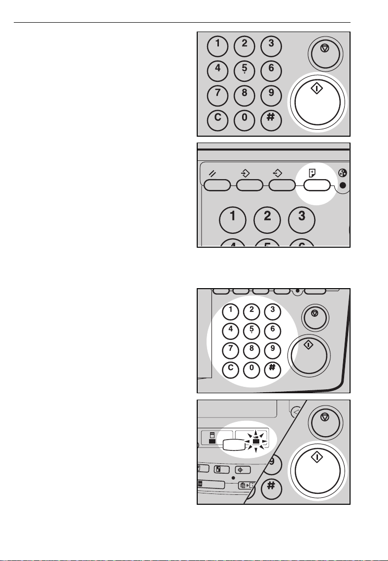
first.
❐ The guides must fit snugly against
both sides of the stack.
Set the required image settings.
3
Make sure that Master Making
4
indicator is lit and then press the
Start key.
Make your prints.
5
84
Page 88

OPTIONAL FUNCTIONS
Combine 2 originals with the document feeder
For details about Combine 2 Originals function, ☛ See page 63.
❐
.
Insert the 2 originals face up.
1
❐ The top original wil l be printed on the
leading part of pr int.
Press the Combine 2 Originals
2
key.
Check the print paper size and
3
the reproduction ratio.
Enter the number of prints using
4
the Number keys.
Make sure that the Master Mak-
5
ing indicator is lit and then press
the Start key.
❐ After the first original is on the mas-
ter, the second or iginal is fe d.
❐ If you set only one original, the
beeper sounds after the first original
is on the master. Set the second
original and the desired image settings. Then, p ress the
85
Start
key.
Page 89

Make sure that Print indicator is
6
lit and then press the Start key.
OPTIONAL FUNCTIONS
86
Page 90

OPTIONAL FUNCTIONS
Printing with One Touch Class mode
For details abou t One Touch Cl ass mode, ☛ see page 47.
❐
To prevent o rigin al mis feed, do not s et or iginal s of dif ferent sizes.
❐
Do not set m ore t han 30 origin als at one tim e.
❐
Set the originals face up into the
1
document feeder.
❐ The originals are fed from the top of
the stack. Make sure that the originals are set in the correct sequence
with the first original on top.
Follow the steps from 2 to 7 on
2
pages 57 ~ 58 or pages 59 ~ 61.
Press the Auto Cycle key.
3
❐ In Auto Cycle mode, printing starts
automatically after a trial print is delivered.
Make sure that the Print indicator
4
is lit and then press the Start
key.
❐ After the last page of each set is fed
out to the paper delivery table, the
tape dispenser drops a strip of paper
on the top of the paper stack. The
next cycle begins.
87
Page 91

OPTIONAL FUNCTIONS
Color Printing Using The Optional Color Drum
Color drum units (red, blue, green, brown, yellow, purple, navy, maroon,
orange and teal) are available as options in addition to the standard black
unit. For making color prints, a separate drum unit is necessary for each
color.
Making color prints
Make sure that the Color Drum
1
indicator is lit.
Make sure that Master Making
2
indicator is lit and then press the
Start key. Check the image position on the trial or proof print.
❐ If the image position is not correct,
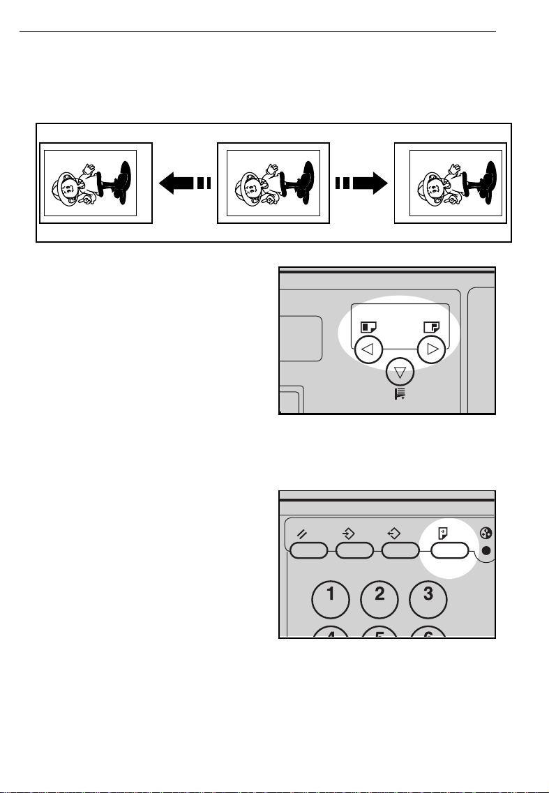
adjust it using the
keys (☛ see page 21) or side plate
fine adjusting di al (☛ see pa ge 22).
Make your prints.
Image Position
3
88
Page 92

OPTIONAL FUNCTIONS
Changing the drum unit for color printing
Open the front door.
1
.
Press the drum rotation button
2
until the beeper sounds.
Lift the lock lever until it locks in
3
position.
Pull out the drum unit handle
4
while pressing the release bar inside the green handle.
❐ If you cannot pull out the drum unit
even when the lamp of the drum rotation butto n is green, p ush the drum
unit handle, then pull out the drum
unit.
89
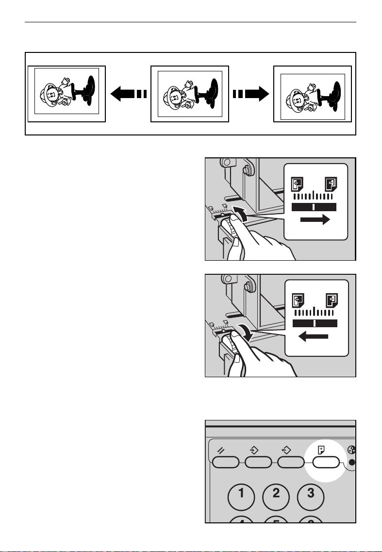
Page 93

Hold the rail on the drum and
5
slide out the drum while pulling
the release towards you.
Remove the drum unit from the
6
machine while holding the upper
drum stay.
Note:
Be careful not to let the drum
unit fall.
Insert the color drum unit along
7
the guide rail.
OPTIONAL FUNCTIONS
Slide in the drum unit until the
8
drum unit locks in position.
90
Page 94

OPTIONAL FUNCTIONS
Lower the drum unit lock lever.
9
Close the front door.
A
❐ Make sure that the Cover Open indi-
cator turns off, and the Color Drum
indicator l ights.
91
Page 95

OPTIONAL FUNCTIONS
Printing in two colors
After printing in one color, you can print in another color on the same side of
the print.
You cannot print in two colors at one time.
❐
Leave the print s for a while be fore print ing on them ag ain to let the ink dry.
❐
Prepare the two originals. Set the
1
first original on the exposure
glass.
Make sure that Master Making
2
indicator is lit and then press the
Start key. Check the image position of the trial or proof print.
❐ If the image position is not correct,
adjust it using the
keys (☛ see page 21) or the side
plate fine adjust ing dial (☛ see page
22).
Image Position
Enter the number of prints using
3
the Number keys.
Make sure that Print indicator is
4
lit and then press the Start key.
92
Page 96

OPTIONAL FUNCTIONS
.
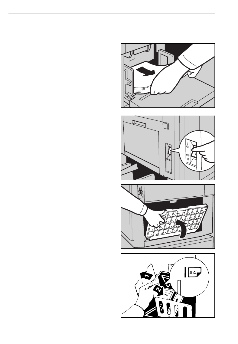
Remove the prints from the paper
5
delivery table and set them on
the paper feed table again as
shown in the illustration.
.
Exchange the drum unit. ☛ See
6
pages 89 ~ 91.
.
Set the second original. Make
7
sure that Master Making indicator is lit and then press the Start
key. Check the image position.
Make sure that Print indicator is
8
lit and then press the Start key.
93
Page 97

CHANGING DEFAULT SETTINGS (SERVICE PROGRAM MODE)
CHANGING DEFAULT SETTINGS (SERVICE
PROGRAM MODE)
Printing needs may vary. To suit your applications, you can adjust the
settings for certain functions.
How To Access Service Programs
The service programs can be set by following this procedure.
If you want to change the settings of a selected service program, ☛ see page 95.
❐
For the serv ice pr ogram menu, ☛ see page 10 2 ~ 107.
❐
Press the SP mode key.
1
❐ The SP-mode menu appears on the
guidance display.
Using the Number keys, enter
2
the desired service program number (SP No.).
❐ For the SP No., ☛ refer to pages
102 ~ 107.
❐ You can go back a menu or move on
using the "<" and ">" keys.
When you want to leave the
3
Service Program mode, press the
Clear Modes key.
94
Page 98

CHANGING DEFAULT SETTINGS (SERVICE PROGRAM MODE)
How To Change Settings of Service Programs
You can regis ter SP No. 5, 20, 29, 84 or 88 and their settin g in the
❐
key (☛ see page 96).
Procedure 1
After entering the desired SP No.,
1
press the Enter key. The value or
mode set at the factory will be
displayed at the end of the second line on the guidance display.
❐ If you designate the wrong SP No.,
press the
re-enter the desired SP No..
Enter the required value or mode
2
using the Number keys.
❐ For the setting of each S P No.,
☛ see page 102 ~ 107.
Clear Modes
key. Then,
CS Mode
.
Press the Enter key to store the
3
desired value or mode.
❐ If you enter the wrong value or
mode, press the
Then, go back to step 1.
95
Clear Modes
key.
Page 99

When you want to leave the
4
Service Program mode, press the
Clear Modes key twice.
CHANGING DEFAULT SETTINGS (SERVICE PROGRAM MODE)
96
Page 100

CHANGING DEFAULT SETTINGS (SERVICE PROGRAM MODE)
Procedure 2
You can change the settings of the following 4 service programs using
procedure 2.
SP No. Mode Default
5 Tape Marker Off 0: No
20 Buzzer On 0: No
29 Photo Background correct 0: No
84 Auto Multi Copy mode selection 0: Multi Copy mode
88 Auto Class mode 0: No
SP No. 5, 20, 29, 84 and 88 can be registered in the CS Mode key. You
can recall registered service programs and their settings and make prints
using the CS Mode key.
For about "Tape Ma rker Off", ☛ see page 102.
❐
For about "Buzzer On", ☛ see page 102.
❐
For about "Phot o Backgrou nd corre ct", ☛ see page s 99 and 104.
❐
For about "A uto M ulti Co py mod e sele ction" , ☛ see pages 100 and 106.
❐
For about "Auto Cl ass mode", ☛ see pa ges 101 and 10 6.
❐
97
 Loading...