

Page 1

Technical Bulletin No. RTB-001
SUBJECT: Ink Cartridge "O" Ring and Rubber Pad DATE: April.30.’91
PAGE: 1 of 2
PREPARED BY: S. Asai
CHECKED BY:
CLASSIFICATION:
Action Required
Troubleshooting
Retrofit Information
[Phenomenon 1]:
There has been a problem with the "O" ring inside the ink cartridge nozzle. The "O" ring
comes off and remains on the nozzle of the ink pump when the ink cartridge is replaced,
or it comes off and stays in the cartridge cap when the cap is removed. This occurs when
the temperature changes radically making the "O" ring contract.
[Countermeasure 1]:
Instruct customers on how to replace the ink cartridge. Have them follow this procedure:
1. Make sure that the "O" ring does not stay on the nozzle of the ink pump before a new
ink cartridge is installed.
If it remains on the nozzle, remove it; otherwise the new ink cartridge cannot be set
properly.
Revision of service manual
Information only
Other
FROM: Copier Technical Support Section
MODEL:
VT2100/2130/2150
VT2300/2500
Ges 5310/5315/5320/5330
Rex 1240/1241/1242/1260
NSH CP310/CP315/CP330
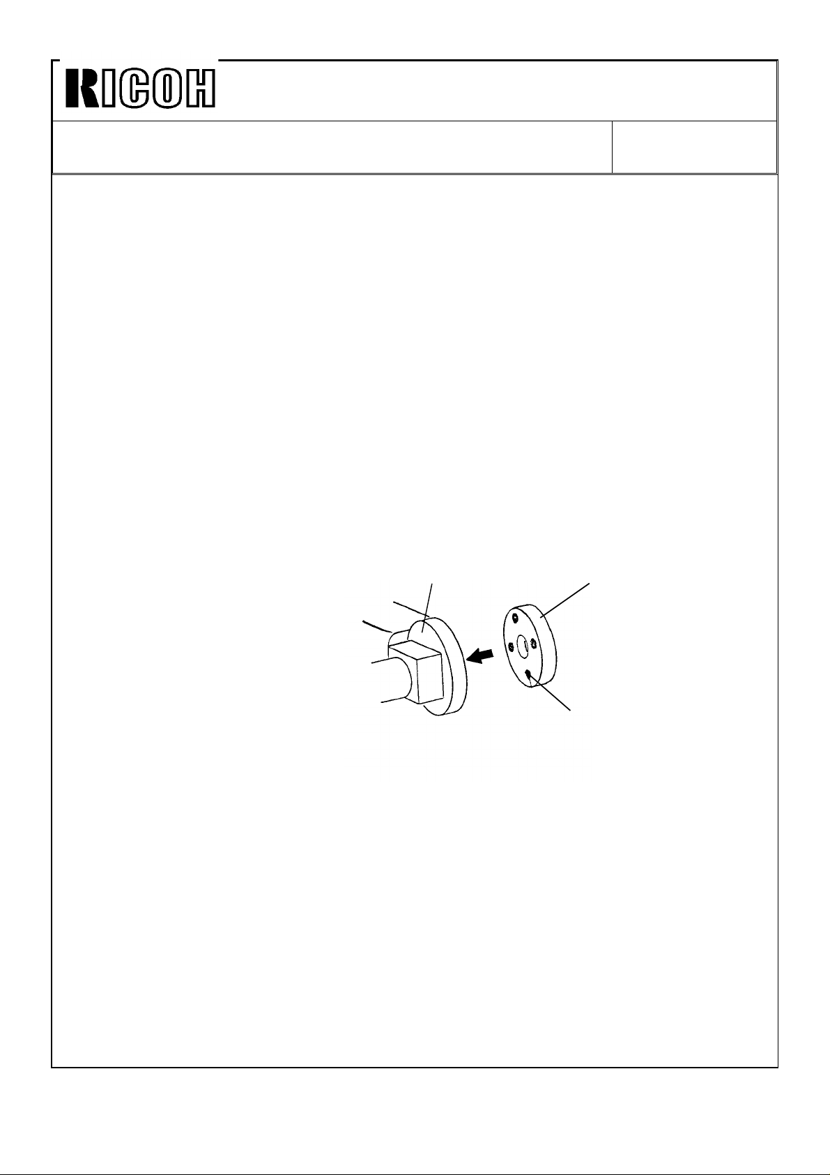
2. Make sure that the "O" ring does not stay in the cartridge cap when the cap is removed
from the ink cartridge nozzle.
If the "O" ring stays in the cartridge cap, remove the "O" ring from the cartridge cap and
install it inside the cartridge nozzle.
Ink Cartridge
Nozzle
Melting Point
"O" ring
Note: To prevent the "O" ring from coming off, more than 2 points between the "O" ring
and the ink cartridge nozzle were soldered as shown above.
This melting process has been implemented since the March ’91 production run.
For a mark of the melting process, a black circle has been stamped on the end of
the lot number. ( Example: Lot No. 1911932 o )
Page 2
Technical Bulletin No. RTB-001
SUBJECT: Ink Cartridge "O" Ring and Rubber Pad DATE: April.30.’91
PAGE: 2 of 2
[Phenomenon 2]:
There has been a problem with the rubber pad located on the ink pump nozzle. It comes
off when the ink cartridge is removed. When no rubber pad remains on the ink pump
nozzle, ink inside the cartridge may not be pumped to the drum even if a new ink
cartridge is installed. This problem does not happen very often.
[Countermeasure 2]:
Apply a strong adhesive ( super glue ) as follows:
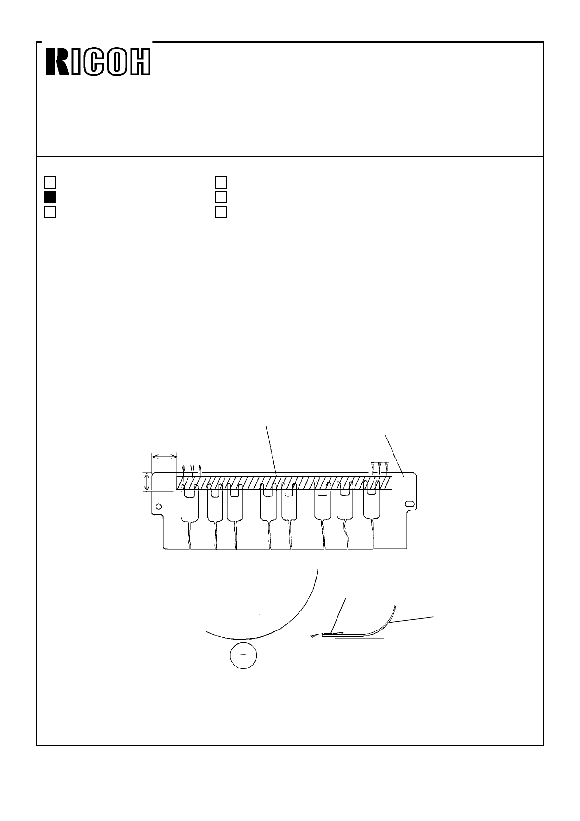
1. Remove the rubber pad with a small screwdriver.
2. Clean the rubber pad and the ink pump nozzle (contacting place of the rubber pad)
with cloth. If stains remain, clean them off with the thermal head cleaner.
3. Apply a little super glue to the 4 points on the rubber pad as shown.
Note: Do not apply too much glue. This is because the rubber pad cannot be inserted
correctly if there is too much glue.
4. Insert the rubber pad into the pump nozzle.
Pump Nozzle
Note: The problem has been fixed for machines with serial numbers listed below. Other
machines not described here will have this problem fixed from the April mass
production run onward.
VT2150: S/N C2801030001VT2300: S/N C2811030001VT2500: S/N C2821030001-
5310: S/N 50211030181- (Europe/Asia version)
5315: S/N 50321030218- (USA version)
5320: S/N 50431030001- (Taiwan version), 50411030001- (Europe/Asia version)
5330: S/N 50521030004- (USA version), 50531030001- (Taiwan version)
50511030244- (Europe/Asia version)
Rubber Pad
Glue
1240: S/N 50211030091- (Europe/Asia version)
1241: S/N 50321030273- (USA version)
1260: S/N 50521030001- (USA version), 50511030527- (Europe/Asia version)
CP310: S/N 52011030061- (Europe/Asia version)
CP330: S/N 50511030727- (Europe/Asia version)
Page 3
Technical Bulletin No. RTB-002
SUBJECT: One dot black line in 64% or 82% reduction mode DATE: June 15 ’91
PAGE: 1 of 2
PREPARED BY: S. Asai
FROM: Copier Technical Support Section
CHECKED BY:
CLASSIFICATION:
Action Required
Troubleshooting
Retrofit Information
Revision of service manual
Information only
Other
MODEL:
VT2100/2130/2150
Ges 5310/5315/5320
Rex 1240/1241/1242
NSH CP310/CP315
[Phenomenon]:
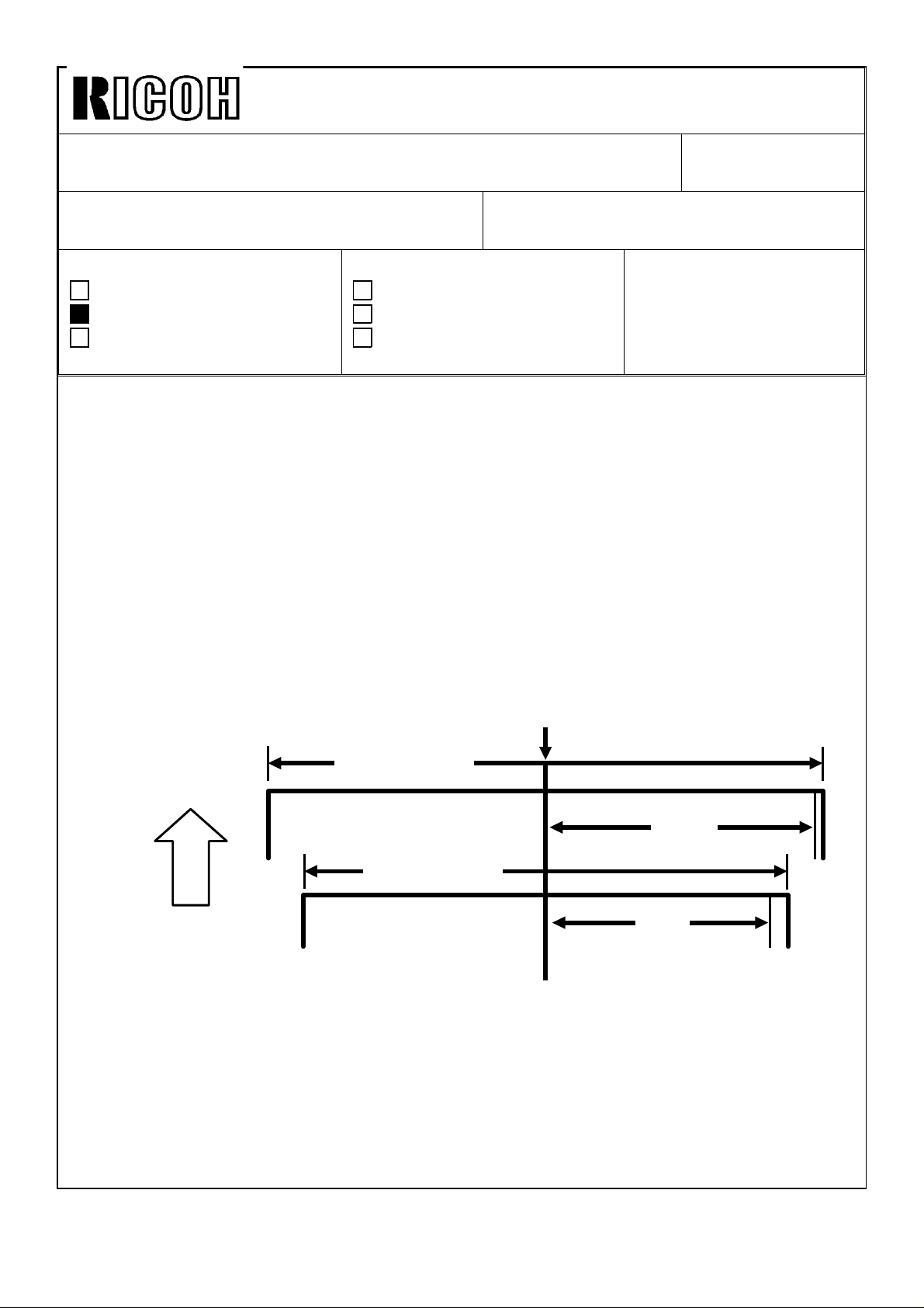
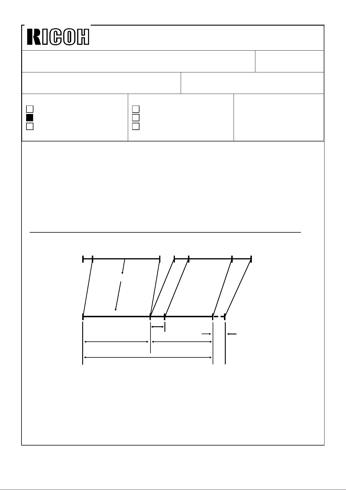
For C211 models, a one dot black line appears on the rear side of the copies when 64%
(on the VT2130, LG version) or 82% (on the VT2100, B4 version) is selected. This
problem does not happen very often.
* In 82% reduction mode, the line appears 127mm from the center.
* In 64% reduction mode, the line appears 100mm from the center.
Note: With the A4 size machine (VT2150), this problem does not occur. This is because
the line would be located out of the maximum printing area when 82% reduction
mode is selected. Also, this problem does not occur on the C212 and C213
models (VT2300 and VT2500). Because the A/D conversion board used on these
machines has a circuit that always changes the dummy pixel data to white data.
Center
B4 width (257 mm)
127 mm
(82%)
LT width (216 mm)
Paper
Feed
Direction
100 mm
(64%)
[Cause]:
The dummy pixel (D31) of the CCD is mixed with the effective pixels because of the timing
delay of the processing circuit. This dummy data is a gray level and is output from the A/D
conversion board as a black data or white data. This depends on the optics adjustment
and/or the Image Density switch position.
Page 4
Technical Bulletin No. RTB-002
SUBJECT: One dot black line in 64% or 82% reduction mode DATE:May 31 ’91
PAGE: 2 of 2
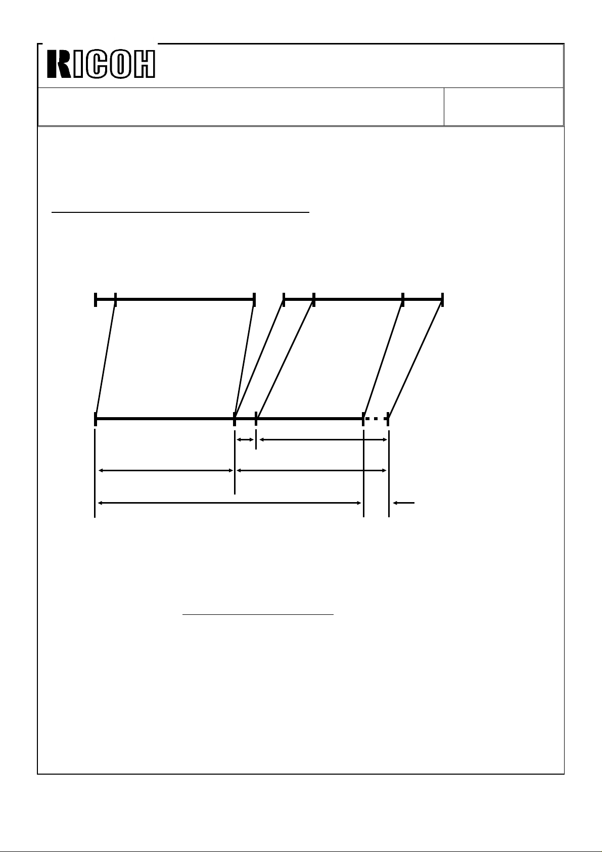
[Temporary Countermeasure]:
In order to discard the dummy pixel (D31) in reduction mode, the reduction ratio of 64%
and 82% was slightly changed. This will allow the D31 dummy pixel data to be discarded
in reduction mode.
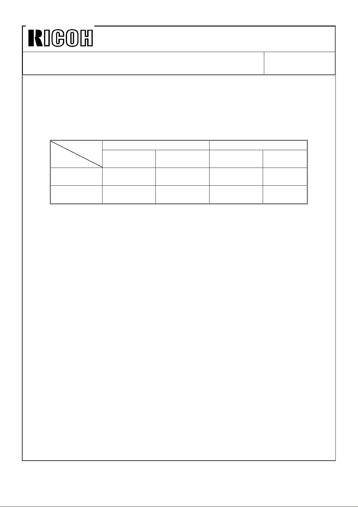
Before modification After modification
Discarded
pixel
Reduction
64%
(LT version)
82%
(A4 version)
Reduction ratio Discarded pixel Reduction ratio
64.3% 9/14 62.5% 5/8
81.8% 9/11 81.3% 13/16
Because of this modification, the PROM on the image processing board has been
modified. The part number of the PROM remains the same. However, a suffix (9th digit)
has been added to the part number as follows:
1. PROM (IC-HN27128AP-20): P/N C2118004A
Note: The above modification has been implemented since 1st mass-production run
except for the following machines:
Ges 5315: S/N 50321030001 to 50321030217 = Total 217 units
Rex 1241: S/N 50321030275 to 50321030277 = Total 3 units
Ges 5320: S/N 50411030001 to 50411030045 = Total 45 units
In the near future, the A/D conversion board will be made the same as that of the
C212 and C213 models (VT2300 and VT2500). This is to delete the one dot black
line and still use the original reduction ratios (64.3% and 81.8%).
Page 5
Technical Bulletin No. RTB-003
SUBJECT: Paper jamming around the drum DATE:June 15 ’91
PAGE: 1 of 1
PREPARED BY: S.Asai
CHECKED BY:
CLASSIFICATION:
Action Required
Troubleshooting
Retrofit Information
[Phenomenon]:
Paper jamming occurs around the drum because of static electricity when the machine is
used under low humidity conditions. Heavy static charges will build up around the master
during the printing run. This happens particularly when thin paper is being used at high
speed rotations. This also happens if the original (and therefore the master on the drum) is
changed.
[Countermeasure]:
Stick the antistatic brush (P/N: C2079010) [A] on the upper second feed roller guide plate
[B] as illustrated below: (The antistatic brush has been registered as a spare part.)
Revision of service manual
Information only
Other
FROM: Copier Technical Support Section
MODEL:
VT2100/2130/2150
VT2300/2500
Ges 5310/5315/5320/5330
Rex 1240/1241/1242/1260
NSH CP310/CP315/CP330
9.5 mm
[A]
[B]
41 mm
[A]
Drum
[B]
Paper Feed Direction
Note: Depending on the type of paper and/or the environment, paper might still jam even
though the antistatic brush was installed on the guide plate.
The occurrence ratio varies according to the environment. If possible, improve the
environmental conditions or move the machine to a better place.
Page 6

Technical Bulletin No. RTB-004
SUBJECT: Paper exit pawl air pump DATE: July 31 ’91
PAGE: 1 of 5
PREPARED BY: S.Asai
CHECKED BY:
CLASSIFICATION:
Action Required
Troubleshooting
Retrofit Information
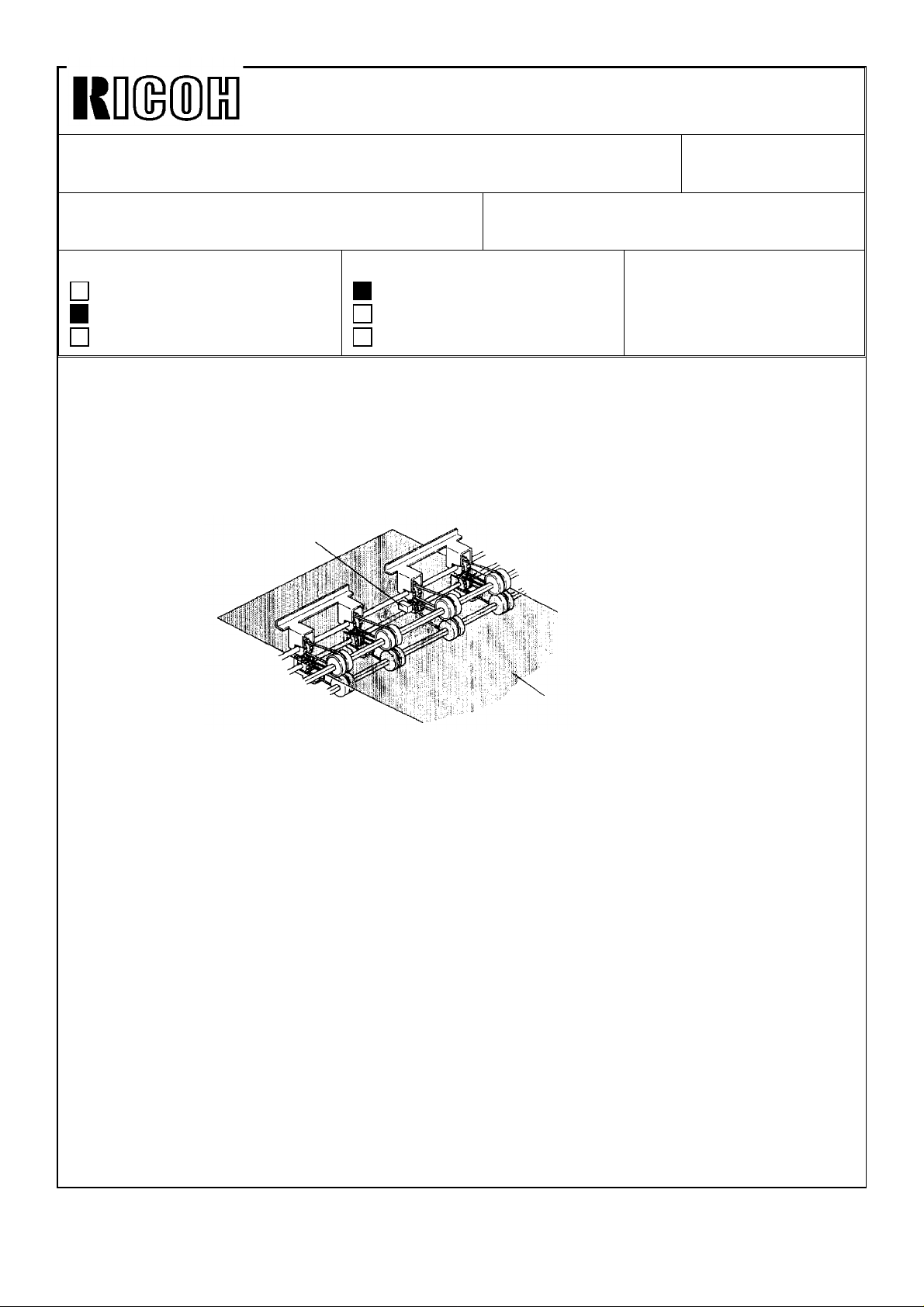
To ease paper separation from the drum, we have registered the air pump kit (P/N
C2119001) as a spare part so that the paper exit pawl air pump mechanism such as that
of the VT3500 (Ges 5375, Rex 1280, NSA CP375) can be installed on the other models
listed above.
Note: When the blank area at the leading edge of copy is too narrow and/or the original
has a large solid image, paper might still jam around the drum even though the
air pump kit was installed on the machine.
Paper exit pawl air pump mechanism:
Revision of service manual
Information only
Other
FROM: Copier Technical Support Section
MODEL:
VT2100/2130/2150
VT2300/2500
Ges 5310/5315/5320/5330
Rex 1240/1241/1242/1260
NSA CP310/CP315/CP330
The paper exit pawl air pump produces a jet of air when the paper exit pawl comes near
the drum surface. This jet of air helps push down on the paper and separate it from the
drum.
Air pump kit installation procedure:
Part check list and installation procedure follow this page.
Page 7
Technical Bulletin No. RTB-004
SUBJECT: Paper exit pawl air pump DATE: July 31 ’91
PAGE: 2 of 5
1. PART CHECK
Make sure that you have all the parts listed below.
* The air pump kit (P/N C2119001) consists of the following parts.
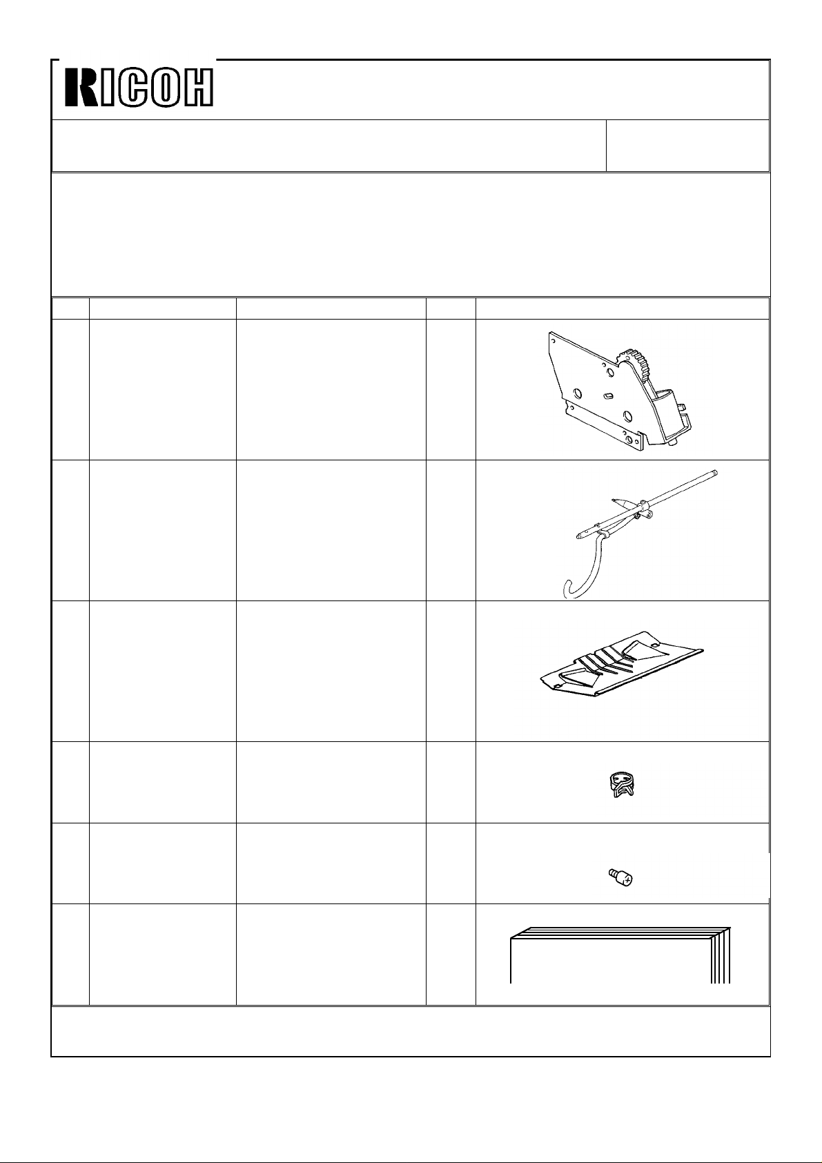
No Part Number Description Qty Shape
1 C2119002 Air Pump Assembly 1
2 C2119003 Exit Pawl Assembly 1
3 C2136201 Shelter Plate 1
4 C2094711 Hose Band 1
5 55066073 Stopper Screw 1
6 C2119004 Installation Procedure 1
AIR PUMP KIT INSTALLATION PROCEDURE
(Page 6 to 9 in English)
Page 8
Technical Bulletin No. RTB-004
SUBJECT: Paper exit pawl air pump DATE: July 31 ’91
PAGE: 3 of 5
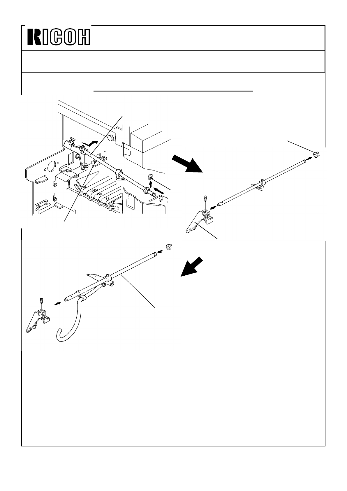
2. INSTALLATION PROCEDURE
[A]
[D]
[B]
[C]
[E]
[F] : P/N C2119003
Note: Before installing the air pump unit, remove the drum, the rear cover, and the
shelter plate.
1. Open the master eject unit and remove the exit pawl assembly [A] (1 E-ring [B] and 1
spring [C]) from the machine .
2. Remove the bushing [D] and the exit pawl lever [E] (1 Allen screw) from the shaft.
3. Mount the above exit pawl lever on the new exit pawl shaft [F] (1 Allen screw used on
the previous shaft) and insert the bushing onto the shaft.
Page 9
Technical Bulletin No. RTB-004
SUBJECT: Paper exit pawl air pump DATE: July 31 ’91
PAGE: 4 of 5
[B]
[C]
[D]
[E]
[A]
Drum
0.5±0.2 mm
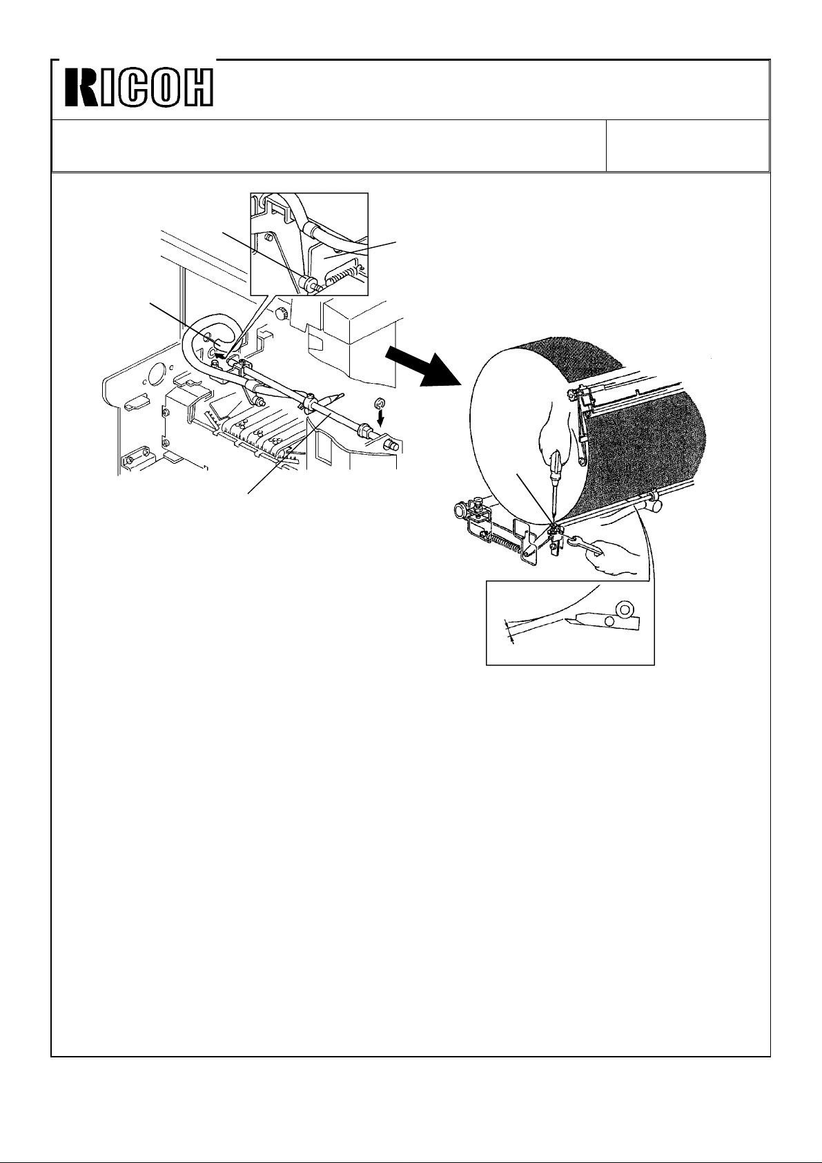
4. Install the new exit pawl unit [A](assembled on the previous page) to the machine (1
E-ring and 1 spring).
Note: Make sure that the collar [B] on the exit pawl lever is correctly placed on the exit
pawl drive cam [C].
5. Insert the edge of the vinyl hose [D] into the hole on the rear side plate as shown.
- EXIT PAWL CLEARANCE ADJUSTMENT -
6. Manually turn on the paper feed and printing pressure solenoids. Using a spanner (10
mm), gradually rotate the drum rotation shaft counterclockwise to move the exit pawl to
the drum.
7. When the printing pressure is applied, adjust the clearance between the drum and the
exit pawl by turning the screw [E]so that it is 0.5±0.2 mm.
Note: Make sure that the exit pawl does not contact the drum surface and the master
clamper several times when the printing pressure is applied.
Page 10

Technical Bulletin No. RTB-004
SUBJECT: Paper exit pawl air pump DATE: July 31 ’91
PAGE: 5 of 5
[E]
[A]
[B] : 55066073
Note: Make sure that the drum stops at its home position. Then, perform the following
procedure.
8. Remove the center support plate [A] originally installed on the machine (5 screws).
9. Install the stopper screw [B] on the rear side plate as shown.
10. Install the new center support plate [C] together with the air pump unit (5 screws).
Note: When installing the air pump unit, make sure that the mark [D] on the air pump
drive gear [E] is located at the top position and that the drum stops at its home
position. Otherwise, the air does not blow from the exit pawl edge at the correct
timing.
[C] : C2119002
[D]
[E]
[F] : C2094711
11. Lay the vinyl hose as shown and install the hose end to the air pump exit with the
hose band [F].
12. Install the new shelter plate (P/N C2136201) on the vacuum unit.
13. Re-install the rear cover (6 screws).
Page 11
Technical Bulletin No. RTB-005
SUBJECT: Black Ink Cartridge Seal DATE: Sep. 30,’91
PAGE: 1 of 1
PREPARED BY: S.Asai
CHECKED BY:
CLASSIFICATION:
Action Required
Troubleshooting
Retrofit Information
To increase ink production, the transparent seal will be removed from the exit of the black
ink cartridge (500cc). For the color inks, the transparent seal remains because the color
inks are more fluid than the black ink.
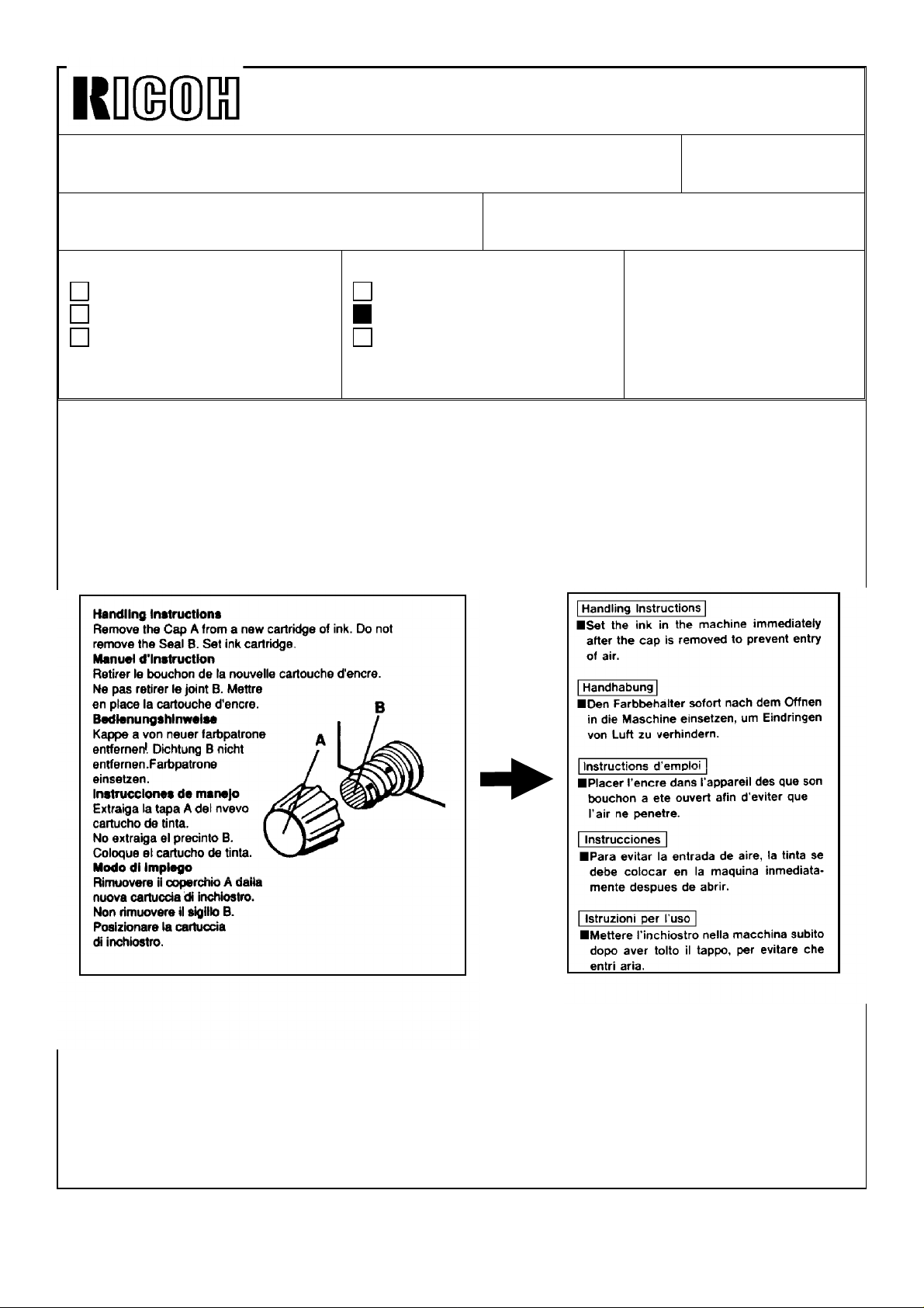
Due to this change, the instructions printed on the black ink cartridge will be changed as
shown below.
OLD
Revision of service manual
Information only
Other
FROM: Copier Technical Support Section
MODEL:
VT2100/2130/2150
VT2300/2500
Ges 5310/5315/5320/5330
Rex 1240/1241/1242/1260
Nsa CP310/CP315/CP330
NEW
This modification will be implemented from the October ’91 production run for the 500cc
ink cartridge.
Page 12
Technical Bulletin No. RTB-006
SUBJECT: F Jam Indication at Power ON DATE: Nov.15,’91
PAGE: 1 of 1
PREPARED BY: S. Asai
CHECKED BY:
CLASSIFICATION:
Action Required
Troubleshooting
Retrofit Information
[Phenomenon]:
F jam indication (Master eject jam indication) lights when the main switch turns on. This is
because the master eject sensor always stays on.
[Adjustment Procedure]:
To ensure that the master eject sensor functions, perform the following adjustment
procedure.
Master Eject Sensor
Revision of service manual
Information only
Other
FROM: Copier Technical Support Section
MODEL:
VT2300/2500
Ges 5330/ Rex 1260
NSA CP330
[A]
1. Clean the sensor surface with cloth dampened with alcohol.
2. Make a master with the blank original.
a. Set the blank original and make about 20 prints.
b. Stop printing and remove the master from the drum.
3. Insert the above master [A] between the upper and the lower eject rollers with the
master film side up as shown.
4. Confirm that the voltage between TP104 and GND line (CN103-5) on the main PCB is
3.5V±0.5V
5. If it is not, adjust it by turning VR104 on the main PCB.
Note: Adjust the voltage under the condition that the master is stretched.
6. Make sure that the voltage is 1.7V or less when no master is under the master eject
sensor.
Note: If the sensor surface stains, the voltage may go over 1.7V
Page 13
Technical Bulletin No. RTB-007
SUBJECT: ROM Change for Combine 2 Originals Mode DATE: Nov.15,’91
PAGE: 1 of 3
PREPARED BY: S. Asai
FROM: Copier Technical Support Section
CHECKED BY:
CLASSIFICATION:
Action Required
Troubleshooting
Retrofit Information
Revision of service manual
Information only
Other
MODEL:
VT2100/2130/2150
Ges 5310/5315/5320
Rex 1240/1241/1242
NSA CP310/CP315
[Phenomenon]:
There have been reports in the field that the Combine 2 Originals mode is canceled when
used with the 71% reduction mode and A4 sideways originals (210 mm width). This
problem occurs on the VT2150 (A4 size machine).
[Causes]:
On the VT2150 (A4 size machine), there is no room for variation in original length
detection in Combine 2 Originals mode. Therefore, if the original feed speed is slightly
slower than the standard speed and/or the original registration sensor actuator for
detecting the original feed length does not move smoothly, this problem may occur in
Combine 2 Originals mode.
Current Original Detection Program in Combine 2 Originals mode on the VT2150:
* Select 71% reduction and use A4 originals.
10 mm
Original
Blank
margin
1st A4 original (210 mm) 2nd A4 original (210 mm)
200 mm
200 x 0.71
10 mm
Blank
margin
200 mm
Master
Master making length 142 mm
1st master making length
142 mm
Maximum master making length=287 mm
Black margin on 2nd
original
10 mm
Remaining length [A]
7 mm
7 mm traing edge image
is not made on the
master in 71% reduction.
On the original, 10 mm
disappears.
1. When the 1st original is fed out, the remaining master making length [A] for the 2nd
original is 145 mm. (287 mm -- 142 mm = 145 mm)
2. In Combine 2 Originals mode, the ROM program detects whether the remaining length
[A] (145 mm) is more than half of the maximum master making length (287 mm / 2
=143.5 mm). If the remaining length is less than 143.5 mm, the Combine 2 Originals
mode is automatically canceled before the 2nd original is fed in.
145 -- 143.5 = 1.5 mm (Normally, it has 1.5 mm leeway)
Page 14
Technical Bulletin No. RTB-007
SUBJECT: ROM Change for Combine 2 Originals Mode DATE: Nov.15,’91
PAGE: 2 of 3
[Countermeasure]:
The ROM program relating to the original length detection in Combine 2 Originals mode
has been modified as follows. This modification is applied to the B4/LG size machines
(VT2100/2130) to standardize the function of Combine 2 Originals mode.
New Program in Combine 2 Originals mode:
1. Apply reduction ratio for 10 mm leading edge image on the 2nd original.
* For example, select 71% reduction and use A4 originals.
10 mm
Original
Blank
margin
Master
1st A4 original (210 mm) 2nd A4 original (210 mm)
200 mm
Blank
margin
142 mm
142 mm
142 mm
Maximum master making length=287 mm
7.1 mm
149.1 mm
200 mm
4.1 mm
4.1 mm trailing edge
image is not made in the
master
2. Added a leeway of 5% of the length in original length detection in Combine 2 Originals
mode.
a. Maximum original size is determined with the following calculation.
Max. Original Size =
Max. Master Making Length
2
x 1.05
÷Reduction Ratio + 10 mm (Blank margin on 1st original)
Max. Master Making Length: B4/LG size machine = 354 mm
A4 size machine = 287 mm
b. The following table shows the maximum original length (Sub-scan line) on each
reduction ratio. If the original length is more than the length mentioned in the table, the
Combine 2 Originals mode is canceled.
Page 15

Technical Bulletin No. RTB-007
SUBJECT: ROM Change for Combine 2 Originals Mode DATE: Nov.15,’91
PAGE: 3 of 3
Printe Size (Model)
B4 Size Machine
Reduction Ratio
(Discarded pixel)
100% 195.9 mm 195.9 mm 160.7 mm
93%
(13/14= 92.85%)
82%
(9/11=81.81%)
71%
(5/7=71.42%)
75%
(3/4=75%)
64%
(9/14=64.28%)
Note: The above figures are true when the image reproduction is exact.
(VT2100)
210.1 mm 210.1 mm 172.3 mm
237.2 mm ---- 194.2 mm
270.2 mm ---- 220.9 mm
---- 257.8 mm ----
---- 299.1 mm ----
LG Size Machine
(VT2130)
A4 Size Machine
(VT2150)
The ROM on the main control board has been modified. The part numbers of the ROM
and the main control board remain. However, a suffix (9th character) has been changed
as follows:
Old P/N New P/N
C2118045C C2118045D (ROM: IC-HN27C256G-20)------------Total Sum Check "BC00"
C2118112E C2118112F (Main Control Board - LG Machine)
C2118113F C2118113G (Main Control Board - B4 Machine)
C2118114F C2118114G (Main Control Board - A4 Machine)
The problem on the VT2150 (A4 size machine) has been fixed for machines with serial
numbers listed below. Other machines not described here will have this problem fixed from
the November mass production run onward.
CP310: S/N 502111000015310: S/N 502111000111240: S/N 50211100121-
VT2150: S/N C2801100*** (9th, 10th, and 11th digits are as follows:)
074, 143-148, 155, 163-165, 169, 170, 175, 177, 178,
182-186, 189, 191-194
Note: If necessary, check the P/N suffix (9th character) of the ROM inside the machine
to judge whether the new ROM has been installed.
Page 16
Technical Bulletin No. RTB-008
SUBJECT: Priport Ink Lot Number DATE: Aug. 15, ’92
PAGE: 1 of 2
PREPARED BY: J. Mochizuki
CHECKED BY:
CLASSIFICATION:
Action Required
Troubleshooting
Retrofit Information
To clarify the ink production dating, the method of lot numbering has been changed as
follows:
Revision of service manual
Information only
Other
FROM: Copier Technical Support Section
MODEL:
VT2100/2130/2150
Ges 5310/5315/5320
Rex 1240/1241/1242
NSA CP310/CP315
Old method
.
1912762
Year
Date
Month
Internal use only
Internal use only
New method
20617–121
Year Month
The above lot number means that the ink is produced on June 17, ’92
Date
Internal use only
Page 17
Technical Bulletin No. RTB-008
SUBJECT: Priport Ink Lot Number DATE: Aug. 15, ’92
PAGE: 2 of 2
The table below shows the new lot numbering start date.
Type of ink New lot numbering
start date
Black 800cc July 13, ’92
Black 500cc July 13, ’92
Color Red 500cc July 13, ’92
Color Blue 500cc July 16, ’92
Color Green 500cc July 14, ’92
Color Brown 500cc July 16, ’92
Page 18

Technica l Bulletin No . RTB-00 9
SUBJECT: Abno rm al image ap pear s o n the m aster DATE: Dec. 31, ’ 92
PAGE: 1 o f 2
PREPARED BY: J. Mo c hizu ki
CHECKED BY: H. Terashita
CLASSIFICATION:
Action Required
Troubleshooting
Retrofit Information
[Symptom]
The fo llow ing abn or mal im age ap p ears on the m ast er reg ar dles s o f the t yp es o f or ig inal:
1. Black copy
2. No image
3. Solid blac k area ap pear s in the m idd le o f th e pr ints
4. Ver tic al wh ite lin e in th e so lid b lac k c o p y
5. 43mm width vertical white line in the center and thin horizontal black lines outside the
white line
[Cause]
Revision of service manual
Information only
Other
FROM: Copier Technical Support Section
MODEL:
Pripo rt VT2105/
Ges 5325/Rex 1250/
NSA CP325
[C]
[A]
[B]
Flat Cable - A/D Co nver sion [ A] ( C2158012) is d amag ed b y th e edg e of th e scan ner sid e
plate cutout [B] and short circuited to the side plate.
[ Co unte rm e asure ]
1. File the edge of the sideplate cutout and cover it with insulating tape.
2. Bind the damaged area of the flat cable with insulating tape.
From December ’92 production, the edge has been covered with rubber pads [C] .
Page 19

Technica l Bulletin No . RTB-00 9
SUBJECT: Abno rm al image ap pear s o n the m aster DATE: Dec. 31, ’ 92
PAGE: 2 o f 2
[Possible abnormal images]
1. Black c o py 2. No imag e
3. Solid b lack area ap pear s
in the middle of the prints
A B C D E F G
H I J K L M N
5. 43mm white line an d h olizon tal
thin lines outside the white line
4. Vertic al wh ite line
in the black copy
Page 20

Technical Bulletin No. RTB-010
SUBJECT: Priport VT2005 Information DATE: July 15, ’94
PAGE: 1 of 2
PREPARED BY: J. Mochizuki
CHECKED BY:
CLASSIFICATION:
Action Required
Troubleshooting
Retrofit Information
The Priport VT2005 has been added to the line-up of the VT2000 series.
The VT2005 is almost the same as the VT2105. Only the difference is that VT2105 has an
automatic document feeder, but the VT2005 does not have it (Originals must be set one
by one in the document feeder.). All the PCBs for the VT2005 are identical to the ones for
the VT2105 (only the DIP SW setting of the main board is different).
Please add the following items and notes to your VT2105 service manual so that the
VT2105 manual can also cover the VT2005.
Revision of service manual
Information only
Other
FROM: 2nd Technical Support Section
MODEL:
Priport VT2005
Ges 5323/Rex 1245/
NST CP323
OVERALL MACHINE INFORMATIONS
Page 1-1
1. SPECIFICATIONS
ADF original capacity: This specification is for the VT2105 only.
Weight: VT2105: 120 V version: 99 kg (217.8 lb)
220/240 V version: 104 kg (228.8 lb)
VT2005: 120 V version: 98 kg (215.6 lb)
220/240 V version: 103 kg (226.6 lb)
Dimensions: Stored: VT2105: 735 mm x 607 mm x 577 mm (29.0"x23.9"x22.8")
(WxDxH) VT2005: 735 mm x 607 mm x 569 mm (29.0"x23.9"x22.5")
Page 1-6
3. ELECTRICAL COMPONENT DESCRIPTIONS
The following components are for the VT2105 only.
3 Original Pressure Solenoid
18 ADF Drive Motor
19 1st Original Sensor
65 ADF Safety Switch
Page 21

Technical Bulletin No. RTB-010
SUBJECT: Priport VT2005 Service Manual DATE: July 15, ’94
PAGE: 2 of 2
SERVICE TABLES
Page 4-2
2.1 DIP SWITCH TABLE (ON THE MAIN BOARD)
The factory setting of the DIP switches is different for the VT2105 and the VT2005.
No. DIP SW Function Factory Setting
2
6
DP102-2 ADF Cover Open VT2105: OFF
VT2005: ON
DP101-4 ADF Operation VT2105: OFF
VT2005: ON
Page 4-6
3.2 OUTPUT MODE
The following output modes are for the VT2105 only:
0032-0 Turns on the ADF drive motor.
0033-0 Turns on the ADF original pressure solenoid.
Page 4-7
3.3 INPUT MODE
The following input mode is for the VT2105 only:
0033-1 SN: 1st Original Detection
Page 22

Technical Bulletin No. RTB-011
SUBJECT: Ink Set-off on Prints or Master Damage When Using the
VT-II Master (For N915/N935/N955 Models Only)
PREPARED BY: H. Kokubo
CHECKED BY: S. Hamano
CLASSIFICATION:
Action Required
Troubleshooting
Retrofit Information
N860: Ricoh VT2005/Gestetner 5323/RexRotary 1245/nashuatec CP323
N865: Ricoh VT2105/Gestetner 5325/RexRotary 1250/nashuatec CP325/ABDICK 6520
N915: Ricoh VT2100/VT2130/VT2150/Gestetner 5310/5315/5320/
RexRotary 1240/1241/1242/nashuatec CP310/CP315
N935: Ricoh VT2300/Gestetner 5330/RexRotary 1260/nashuatec CP330
N955: Ricoh VT2500
There are two types of master for the N915/N935/N955 models. They are the VT-II master
(RICOH VT-II-M/S, NRG CPMT8/9) and VT master (RICOH VT-M/S, NRG CPMT4/5). The
VT-II master is slightly more sensitive to the heat of the thermal head than the old VT
master. (The VT-II master has started being used instead of the old VT master.) When the
VT-II master is used, the following symptom might occur:
Revision of service manual
Information only
Other
FROM: 2nd Technical Support Section
MODEL:
Priport N860/N865/N915/
N935/N955
(N915/N935/N955 Only)
DATE: Dec. 15, ’94
PAGE: 1 of 2
SYMPTOM
- Amount of ink transferred on prints increases due to larger holes made by the thermal
head on the master than those of the old VT master. As a result, ink set-off on the
reverse side of prints will increase.
- The thermal head makes too large holes on the master and some parts of the
master surface (the polyester film layer) are peeled off during printing. The damaged
parts will appear as black patches on prints.
SOLUTION
Install a special ROM on the image processing PCB to enable the adjustment of the
thermal head energy with the DIP switches.
1. Replace the ROM on the image processing PCB (IC422 P/N-C211 8004 for the N915
models, IC432 P/N-C213 8004 for the N935/N955 models) with the following one.
- For N915 models: P/N-C211 9006 (IC - HN27128AP-20)
- For N935/N955 models:P/N-C213 9005 (IC - HN27128AP-20)
NOTE: - These ROMs are available as normal service parts.
- The ROMs for the N915 and N935/N955 models are different.
Page 23

Technical Bulletin No. RTB-011
SUBJECT: Ink Set-off on Prints or Master Damage When Using the
VT-II Master
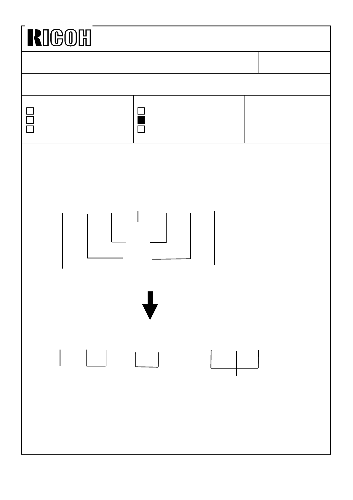
2. The thermal head energy can be adjusted using number 5 and 6 of DPS400 on the
image processing PCB as follows:
DPS400-5 ON ON OFF OFF
DPS400-6 ON OFF ON OFF
Thermal Head
Energy
NOTE: DPS400-5 and -6 are also for the thermal head energy adjustment even with the
normal ROM, but the special ROM allows for much wider adjustment range as
indicated in the above table.
3. Set DPS400-5 to OFF and DPS400-6 to ON to reduce the thermal head energy by
-15%.
STANDARD -10% -15% -20%
DATE: Dec. 15, ’94
PAGE: 2 of 2
NOTE:
1) The thermal head energy can also be reduced by reducing the input voltage with the
potentiometer in the power supply unit (see service manual page 5-23 "THERMAL
HEAD VOLTAGE ADJUSTMENT"). However, this is not effective against the above
symptom and the above solution must be used. The new ROMs enable the adjustment
of the pulse length which determines the period that voltage is applied to the thermal
head.
2) After you reduce the thermal head energy, tiny white spots tend to be more visible in
solid-fill image areas. This is just like the images made with the old VT master. The
density of the solid-fill images looks slightly lighter. (Therefore, you should not reduce
the thermal head energy more than -15% as indicated in the above procedure.)
3) If the fences on the paper delivery table are not adjusted exactly to the paper size, ink
set-off on the reverse side of prints will increase. Instruct the operator if he is not
familiar with this.
Page 24

Technical Bulletin No. RTB-012
SUBJECT: Ink Pump Improvement (For the N860/N865/N915/
N935/N955 Only)
PREPARED BY: H. Kokubo
CHECKED BY: M. Iwasa
CLASSIFICATION:
Action Required
Troubleshooting
Retrofit Information
N850: Ricoh VT2200/Gestetner 5327/RexRotary 1252/nashuatec CP327/ABDICK 6530
N860: Ricoh VT2005/Gestetner 5323/RexRotary 1245/nashuatec CP323
N865: Ricoh VT2105/Gestetner 5325/RexRotary 1250/nashuatec CP325/ABDICK 6520
N915: Ricoh VT2100VT/2130/VT2150/Gestetner 5310/5315/5320/
RexRotary 1240/1241/1242/nashuatec CP310/CP315
N935: Ricoh VT2300/Gestetner 5330/RexRotary 1260/nashuatec CP330
N955: Ricoh VT2500
Information for the N850 starts from this bulletin. RTB’s number 1 to 11 are for the
other models only.
Revision of service manual
Information only
Other
FROM: 2nd Technical Support Section
MODEL:
Priport
N850/N860/N865/N915/
N935/N955
DATE: Nov. 15, ’95
PAGE: 1 of 2
To ensure that all ink in the cartridge is supplied,
a spring has been added inside the ink
pump as shown to the right. The spring
ensures that the small ball, which is used as a
valve, is pushed back properly.
This modification has been applied from the
September 1995 production runs of all
Priport series models. The part numbers of
the ink pump assemblies remain the same.
(Note that the N850 and RN925 have been
using the new type from the first mass
production.)
There are three types of ink pump. They
are the NA/NB type that can hold the
1000 cc ink cartridge, the N type that can
hold the 600 cc ink cartridge only, and the
N810 type that is for the N810 and N810-II
only. See the following table for the
applicable models.
TYPE OF
INK PUMP
NA/NB NA-2, NA-3, NB-2
N N865, N860, N915, N935, N955, and all SS series models.
N810 N810, N810-II
Newly Added
Spring
Cross-section of the Bottom Part
APPLICABLE MODELS
Packing
Valve
Socket
of the Ink Pump
Page 25

Technical Bulletin No. RTB-012
SUBJECT: Ink Pump Improvement (For the N860/N865/N915/
N935/N955 Only)
There are two types of spring for these three types of the ink pump. The part numbers are:
C222 4710 (Pump Spring - 21 mm) : For the NA/NB type ink pump.
C224 4715 (Pump Spring - 13 mm) : For the N and N810 type ink pumps.
DATE: Nov. 15, ’95
PAGE: 2 of 2
SOLUTION IN THE FIELD
For the field machines, you can install the spring after removing the socket (with two
screws). (It takes longer to replace the whole pump assembly.)
CAUTION: When you remove the socket, ink will leak. Be sure to place absorbant
material to prevent the floor from becoming dirty with ink.
NOTE: 1. There is a packing between the socket and housing (see the illustration on the
previous page). If it is damaged, you may have to replace the packing at the same
time. (Normally, this is not required.) The part number is:
C200 4827 (Packing - Pump Socket)
2. A rubber packing is used as shown below in order to ensure that the nozzle of
the ink cartridge tightly contacts the pump socket. Check if this part is dislocated.
The rubber packing used in the N810, the N865, and the other later models is
adhered with glue, but it is not adhered for the other older models.
C200 4826
(Pump Rubber)
Page 26

Technical Bulletin No. RTB-013
SUBJECT: Master Eject Belt Modification DATE: Mar. 31, ’96
PAGE: 1 of 2
PREPARED BY: H. Kokubo
CHECKED BY: M. Iwasa
CLASSIFICATION:
Action Required
Troubleshooting
Retrofit Information
N850: Ricoh VT2200/Gestetner 5327/RexRotary 1252/nashuatec CP327/ABDICK 6530
N860: Ricoh VT2005/Gestetner 5323/RexRotary 1245/nashuatec CP323
N865: Ricoh VT2105/Gestetner 5325/RexRotary 1250/nashuatec CP325/ABDICK 6520
N915: Ricoh VT2100/VT2130/VT2150/Gestetner 5310/5315/5320/
RexRotary 1240/1241/1242/nashuatec CP310/CP315
N935: Ricoh VT2300/Gestetner 5330/RexRotary 1260/nashuatec CP330
N955: Ricoh VT2500
Revision of service manual
Information only
Other
FROM: Technical Support Section
MODEL:
Priport
N850/N860/N865/N915/
N935/N955
PROBLEM
Master eject jams frequently occur. In the worst case, the upper or lower master eject belts
slip off the rollers.
CAUSE
At the March 1995 production of all PRIPORT models, the vendor who produced the upper
and lower master eject belts was changed. (The part numbers were not changed because
there was no change in configuration.) Since then, all PRIPORT models have been using
the belts manufactured by the new vendor.
Recently it was found that some of these parts tend to stretch and can cause the problem,
as stated above, due to part variation. (The occurrence of the problem varies from one lot
to another.)
Page 27

Technical Bulletin No. RTB-013
SUBJECT: Master Eject Belt Modification DATE: Mar. 31, ’96
PAGE: 2 of 2
SOLUTION
The upper and lower master eject belts will be modified as follows:
Inter-
Old P/N New P/N Description Q’ty used
C219 3545 C219 3605 Upper Belt
C219 3546 C219 3606 Lower Belt
4 → 4
* (5 → 5)
4 → 4
* (5 → 5)
changeability
x/o
x/o
Applicable Models
NB2, N850, RN925, NA33
* : The number of both
parts used for the NA33
is 5.
C200 3545 C219 3605 Upper Belt
C200 3546 C219 3606 Lower Belt
NOTE: There are two types of old part numbers as shown in the table. Both these types
will be changed into a new type of upper and lower belt.
The new upper and lower belts will be implemented into the production from April 1996.
For the service parts, the SPC will have the new parts in stock soon.
4 → 4
* (5 → 5)
4 → 4
* (5 → 5)
x/o
x/o
NA3, NA2, N865, and
other older models.
* : The number of both
parts used for the NA3
and NA2 is 5.
Page 28

Technical Bulletin No. RTB-014
SUBJECT: Worn Main Drive Gear (N860/N865 Only) DATE: June 15, ’96
PAGE: 1 of 2
PREPARED BY: H. Kokubo FROM: Priport Service Planning Section
CLASSIFICATION:
Action Required
Troubleshooting
Retrofit Information
N850: Ricoh VT2200/Gestetner 5327/RexRotary 1252/nashuatec CP327/ABDICK 6530
N860: Ricoh VT2005/Gestetner 5323/RexRotary 1245/nashuatec CP323
N865: Ricoh VT2105/Gestetner 5325/RexRotary 1250/nashuatec CP325/ABDICK 6520
N915: Ricoh VT2100VT/2130/VT2150/Gestetner 5310/5315/5320/
RexRotary 1240/1241/1242/nashuatec CP310/CP315
N935: Ricoh VT2300/Gestetner 5330/RexRotary 1260/nashuatec CP330
N955: Ricoh VT2500
It was found that gears C2032215 and C2032326 (see the illustration on the next page)
can rapidly wear out if they are not greased. In particular, gear C2032215 wears out faster
(after abo ut 30,000 to 50,000 copies) .
Revision of service manual
Information only
Other
MODEL:
Priport
N850/N860/N865/N915/
N935/N955
It was also found on the production lines that some machines which were manufactured
during the period from the end of 1994 to May 1995 have a lack of greasing for these
gears. From April 1995, an inspection process was added to check the greasing of these
gears.
NOTE: The N850, N915, N935, and N955 models do not have this problem. The N850 started
manufacture after May 1995, and there was no production of the other models during that
period. Therefore, it is only possible for the N860 and N865 to have this problem.
Page 29

Technical Bulletin No. RTB-014
SUBJECT: Worn Main Drive Gear (N860/N865 Only) DATE: June 15, ’96
PAGE: 2 of 2
RECOMMENDATIONS
Grease the gears (evenly on the surface of the gear C2032215) in the following cases:
1. For the machines detailed above (the N860 and N865 manufactured between the end
of 1994 and May 1995), check if grease is properly applied and grease if necessary.
2. Grease the gears every time when they are replaced.
3. Grease at yearly PM intervals (as mentioned in the service manual).
Gear: C203 2215
Gear: C203 2326
Page 30

PAGE: 1 OF 2
Technical Bulletin No. RTB-015
SUBJECT: Paper Table Drive Error E-02
ISSUED ON: July 31, 1996
(N850 and NA33 Only)
CLASSIFICATION:
Action Required
Troubleshooting
Retrofit Information
Revision of service manual
Information only
Other
ISSUED BY:
H. Kokubo,
Priport Service Planning Section
MODEL: PRIPORT
N850: Ricoh VT2200/Gestetner 5327/RexRotary 1252/nashuatec CP327/ABDICK 6530
N860: Ricoh VT2005/Gestetner 5323/RexRotary 1245/nashuatec CP323
N865: Ricoh VT2105/Gestetner 5325/RexRotary 1250/nashuatec CP325/ABDICK 6520
N915: Ricoh VT2100/VT2130/VT2150/Gestetner 5310/5315/5320/RexRotary 1240/1241/1242/
nashuatec CP310/CP315
N935: Ricoh VT2300/Gestetner 5330/RexRotary 1260/nashuatec CP330
N955: Ricoh VT2500
SYMPTOM:
The paper feed table is not driven. Service call status code E-02: paper table drive error
is displayed.
CAUSE:
The dc motor that drives the table occasionally generates electrical noise when it starts
rotating. This electrical noise is input into the ac drive board and damages IC301 on the
board.
Electrical noise tends to be generated especially when the motor is still new. While the
motor turns, the brushes inside are not yet worn in and this can cause electrical noise to
occur.
Since a dc motor of this type is used in the N850 (Ricoh VT2200/Gestetner 5327/
RexRotary 1252/nashuatec CP327/ABDICK 6530) and NA33 (Ricoh VT3800/ Gestetner
5385/RexRotary 1290/nashuatec CP385/ABDICK 6790) models only, this problem does
not occur on the other PRIPORT models.
SOLUTION:
To prevent the electrical noise from being generated, a harness which contains two
capacitors will be installed between the ac drive board and dc motor from the August
1996 production.
-------- Continued --------------------------------------------------------------------------------------------------
Page 31

Technical Bulletin No. RTB-015
For the field units, the following part has been registered as a service part:
Motor Relay Harness Kit: P/N-C223 8131
NOTE: The above part includes:
- One Relay Harness (includes the capacitors)
- One Ty-wrap
- One Grounding Screw (M4 x 6)
In the field, install the kit as shown below:
NOTE:
For N850
- The layout of the dc motor is slightly different between the N850 and NA33 models as
shown. To prevent the relay harness from being caught by the gears, firmly secure it with
the Ty-wrap as shown in the illustrations for each model.
- Since the Ty-wrap is too long for the N850 model, cut off the excess, as shown.
Cut off the excess
PAGE: 2 OF 2
Ty-wrap
Grounding
Screw
Blue
Connector
of Relay
Harness
DC Motor
Ty-wrap
White
Connector
of Relay
Harness
For NA33
White
Connector
of Relay
Harness
Blue
Connector
of Relay
Harness
Grounding
Screw
Page 32

PAGE: 1 OF 6
Technical Bulletin No. RTB-016
SUBJECT: Paper Leading Edge Dirty with Ink ISSUED ON: August 31, 1996
CLASSIFICATION:
Action Required
Troubleshooting
Retrofit Information
Revision of service manual
Information only
Other
ISSUED BY:
H. Kokubo,
Priport Service Planning Section
MODEL: PRIPORT
N850: Ricoh VT2200/Gestetner 5327/RexRotary 1252/nashuatec CP327/ABDICK 6530/SVN3200DNP
N860: Ricoh VT2005/Gestetner 5323/RexRotary 1245/nashuatec CP323
N865: Ricoh VT2105/Gestetner 5325/RexRotary 1250/nashuatec CP325/ABDICK 6520
N915: Ricoh VT2100/VT2130/VT2150/Gestetner 5310/5315/5320/RexRotary 1240/1241/1242/
nashuatec CP310/CP315
N935: Ricoh VT2300/Gestetner 5330/RexRotary 1260/nashuatec CP330
N955: Ricoh VT2500
SYMPTOM:
During a long printing run, unwanted ink appears at the leading edge of copies. At first, it
is very hard to see, but it becomes more visible as the printing continues.
CAUSE:
Due to the rough edges of the paper, the master wrapped around the drum becomes
damaged.
Just when the leading edge of the paper reaches under the drum, it is pressed against
the drum surface, so that the master is wrapped around by the press roller. Due to this
repeating action, the master’s surface is gradually torn where the paper leading edge
contacts it.
Also, if paper generates a lot of paper dust, this is accumulated on the press roller
surface and damages the master in the same manner.
Normally, even if the master is damaged, there is no ink around the area beneath the
master where the paper leading edge contacts (there are no holes in the metal screen).
However, after a long printing run, ink leaks onto this area and is transferred to the paper
through the damaged part of the master.
SOLUTION:
1. Change the paper type. Re-setting the paper on the paper feed table upside-down (so
that the rough edge of the paper faces downward) may also solve the problem.
2. Change the image position on the paper slightly using the IMAGE SHIFTING key
before the leading edge of the paper becomes dirty with ink.
-------- Continued --------------------------------------------------------------------------------------------------
Page 33

PAGE: 2 OF 6
Technical Bulletin No. RTB-016
3. Cover the leading edge part of the cloth screen on the drum with tape, so that ink does
not leak even when the master is damaged.
Instructions and remarks for installing the tape for each PRIPORT model are as follows:
Remarks general to all models:
• It is recommended to use:
Teflon Tape - 19 mm: P/N-A012 9112
• The position of the tape for each model has been determined to maintain the
specified leading edge blank margin for copies. (The specification is 10 mm for the
NA2/N915/935/955 models, 8 mm for the NA3 model, and 5 mm for the other
models.)
• Even after installing the tape, the same problem may occur if the leading edge
registration of copies is not adjusted properly (if the paper feed timing is delayed). At
first, check that the leading edge registration of copies is OK. If it is out of
specification, follow the "SECOND FEED ROLLER START TIMING" adjustment
procedure in the service manual. (For the N810 and N810-II models, follow the
"LEADING EDGE REGISTRATION ADJUSTMENT" procedure.)
• For each model, strip(s) of sandpaper are used on the leading edge part of the cloth
screen. This prevents the master wrapped around the drum from slipping out of the
master clamper due to the repeating press roller on/off action. Avoid covering all the
sandpaper when you install the tape. (To adhere the tape firmly, some area of the
sand paper should be covered. Details are in the instructions for each model on the
following pages.)
• Even if the sandpaper is not used on the cloth screen (the old type cloth screen),
install the tape at the same position by measuring the distance from the edge of the
cloth screen. (Refer to the distance between the edge of the screen and the sand
paper, which is shown in the following illustrations for each model.)
Page 34

PAGE: 3 OF 6
Technical Bulletin No. RTB-016
For RN925, NB2, N850, N860, N865, N915, N935, and N955 Models
RN925: Ricoh VT2400/Gestetner 5340/RexRotary 1255/nashuatec CP340/ABDICK 6550
NB2: Ricoh VT2600/VT2630/Gestetner 5360/RexRotary 1270/nashuatec CP360
N850: Ricoh VT2200/Gestetner 5327/RexRotary 1252/nashuatec CP327/ABDICK 6530/SVN3200DNP
N860: Ricoh VT2005/Gestetner 5323/RexRotary 1245/nashuatec CP323
N865: Ricoh VT2105/Gestetner 5325/RexRotary 1250/nashuatec CP325/ABDICK 6520
N915: Ricoh VT2100/VT2130/VT2150/Gestetner 5310/5315/5320/RexRotary 1240/1241/1242/
nashuatec CP310/CP315
N935: Ricoh VT2300/Gestetner 5330/RexRotary 1260/nashuatec CP330
N955: Ricoh VT2500
Sandpaper
25 mm
63 ~ 64 mm
5 mm
19 mm
10 ~ 11 mm
25 mm
Tape
REMARKS:
• Cut the tape where it covers the sandpaper as shown.
left as shown to hold the tape on the screen firmly.) Be careful not to damage the
cloth screen surface.
(The indicated area must be
• Cut both edges of the tape as indicated.
• Even if the sandpaper is not used on the cloth screen (the old type cloth screen),
install tape at the same position by measuring the distance from the edge of the
cloth screen to the lower edge of the tape (between 63 and 64 mm).
• Since the specification of the leading edge blank margin for the N915/935/955
models is 10 mm (5 mm for the other models), it is permissible to install the tape
5 mm lower than the position indicated above.
Page 35

PAGE: 4 OF 6
Technical Bulletin No. RTB-016
For NA33 model
NA33: Ricoh VT3800/Gestetner 5385/RexRotary 1290/nashuatec CP385/ABDICK 6790/SVN3300DNP
Cut tape here.
Sandpaper
63.5 ~ 64.5 mm
Cut tape here.
19 mm
12.5 ~ 13.5 mm
Tape
REMARKS:
• Cut the tape where it covers the upper strip of sandpaper as shown. Be careful not
to damage the cloth screen surface.
• Cut both edges of the tape at the edge of the
over the drum flanges.
metal screen. Do not let the tape ride
Page 36

Technical Bulletin No. RTB-016
For NA3 and NA2 Models
NA2: Ricoh VT3500/Gestetner 5375/RexRotary 1280/nashuatec CP375/ABDICK 6720
NA3: Ricoh VT3600/Gestetner 5380/RexRotary 1285/nashuatec CP380/ABDICK 6770
Sandpaper
PAGE: 5 OF 6
66.5 ~ 67.5 mm
13.5 ~ 14.5 mm
19 mm
Tape
REMARKS:
• The position of the tape is slightly different from that for the NA33 model since the
specification of the leading edge blank margin is different. (The position of the
sandpaper is also different.) The upper edge of the tape should meet between the
two strips of sandpaper. You do not have to cut the tape (unlike in the case of the
NA33 model).
• Cut both edges of the tape at the edge of the
over the drum flanges.
• Even if the sandpaper is not used on the cloth screen (the old type cloth screen),
install the tape at the same position by measuring the distance from the edge of the
cloth screen to the lower edge of the tape (between 66.5 and 67.5 mm).
• Since the specification of the leading edge blank margin for the NA2 model is 10
mm (8 mm for the NA3 model), it is permissible to install the tape
the position indicated above (NA2 only).
metal screen. Do not let the tape ride
2 mm lower than
Page 37

PAGE: 6 OF 6
Technical Bulletin No. RTB-016
For N810 and N810-II Models
N810: Ricoh VT1730/Gestetner 5303/RexRotary 1220/nashuatec CP303/ABDICK 6120
N810-II: Ricoh VT1800/Gestetner 5304/RexRotary 1222/nashuatec CP304/ABDICK 6130/SVN3100DNP
Sandpaper
5 mm
Black Patch
4 mm
Tape
Black Patch
19 mm
8.5 ~ 9.5 mm5 mm
REMARKS:
• Cut the tape where it covers the sandpaper as shown.
(The indicated area must be
left as shown to hold the tape on the screen firmly.) Be careful not to damage the
cloth screen surface.
• Also, cut the tape where it covers the black patches (for the drum master
detection sensor) as shown. It they are covered over, drum master detection
does not work properly.
• Cut both edges of the tape at the edge of the
metal screen. Do not let the tape ride
over the drum flanges.
• Even if the sandpaper is not used on the cloth screen (the old type cloth screen),
install tape at the same position by measuring the distance from the edge of the
black patch to the lower edge of the tape (between 8.5 and 9.5 mm).
Page 38

PAGE: 1 OF 2
Technical Bulletin No. RTB-017
SUBJECT: Add Ink Indicator (Software Modification)
ISSUED ON: August 31, 1996
- N850 Only -
CLASSIFICATION:
Action Required
Troubleshooting
Retrofit Information
Revision of service manual
Information only
Other
ISSUED BY:
H. Kokubo,
Priport Service Planning Section
MODEL: PRIPORT
N850: Ricoh VT2200/Gestetner 5327/RexRotary 1252/nashuatec CP327/ABDICK 6530/SVN3200DNP
N860: Ricoh VT2005/Gestetner 5323/RexRotary 1245/nashuatec CP323
N865: Ricoh VT2105/Gestetner 5325/RexRotary 1250/nashuatec CP325/ABDICK 6520
N915: Ricoh VT2100/VT2130/VT2150/Gestetner 5310/5315/5320/RexRotary 1240/1241/1242/
nashuatec CP310/CP315
N935: Ricoh VT2300/Gestetner 5330/RexRotary 1260/nashuatec CP330
N955: Ricoh VT2500
Problems of Current Software:
At installation of a new machine, the ADD INK INDICATOR is not reset even after an ink
cartridge is installed and the drum idling procedure is carried out.
This problem occurs only in the N850 models.
CAUSE:
At installation, to start rotating the drum and to transfer ink to the drum, the drum idling
procedure: "While holding down the "0" key on the operation panel, press the Reset
key", is used.
In the other Priport models, if sufficient ink is detected after performing the above drum
idling procedure, the ADD INK INDICATOR is reset (disappears) even without depressing
the RESET key. However, in the N850 and RN925 models, the ADD INK INDICATOR is
NOT reset by the drum idling procedure even if there is enough ink. (
depressing the RESET key.)
This problem does not occur if you do not use the drum idling procedure. When the ADD
INK INDICATOR is displayed during the normal printing procedure, it can be reset
properly by depressing the RESET key.
It is reset by
Page 39

PAGE: 2 OF 2
Technical Bulletin No. RTB-017
SOLUTION:
The software has been changed from the August 1996 production.
The ADD INK INDICATOR is reset if sufficient ink is detected after performing the drum
idling procedure, just like the other Priport models.
The suffix of the MPU board has been advanced and the part number of the ROM has
been changed as follows:
Old P/N New P/N Description Note
C224 8045C C224 8075A IC134 - M27C512-15F1 New Check Sum: 95FH
C224 8042H C224 8042J MPU Board
Page 40

PAGE: 1 OF 3
Technical Bulletin No. RTB-018
SUBJECT: Additional Instructions for the ADF Unit
ISSUED ON: January 15, 1997
Installation/Removal - GOLD Only CLASSIFICATION:
Action Required
Troubleshooting
Retrofit Information
Revision of service manual
Information only
Other
ISSUED BY:
H. Kokubo,
Priport Service Planning Section
MODEL: PRIPORT
GOLD: Ricoh VT2250/VT2240/Gestetner 5329(L)/RexRotary 1254(L)/nashuatec CP329(L)/
ABDICK 6560/SVN3250DNP
N850: Ricoh VT2200/Gestetner 5327/RexRotary 1252/nashuatec CP327/ABDICK 6530/SVN3200DNP
N860: Ricoh VT2005/Gestetner 5323/RexRotary 1245/nashuatec CP323
N865: Ricoh VT2105/Gestetner 5325/RexRotary 1250/nashuatec CP325/ABDICK 6520
N915: Ricoh VT2100/VT2130/VT2150/Gestetner 5310/5315/5320/RexRotary 1240/1241/1242/
nashuatec CP310/CP315
N935: Ricoh VT2300/Gestetner 5330/RexRotary 1260/nashuatec CP330
N955: Ricoh VT2500
Information for the GOLD starts from this bulletin. RTB numbers 1 to 17 are for the
other models only.
The following two remarks must always be noted (in addition to the
ADF unit installation/removal procedures in the service manual) when
you install or remove the ADF unit:
[A]
[B]
[B]
1. When you install the ADF unit [A] on the scanner unit, make sure to insert the tab
[B] as shown above.
Page 41

PAGE: 2 OF 3
Technical Bulletin No. RTB-018
[C]
NOTE: If you do not follow the above instruction and the tab rides over the scanner unit frame, the
ADF unit leans toward the right. There are guides [C], which are to guide both ends of the
carriage, beneath the right end of the ADF (see the illustration above). Thus, these guides are
just slightly lowered.
As a result, the carriage tends to be caught by the edge of the guides [C] while the carriage
moves toward the original scanning position for the ADF mode. Even if the carriage is stopped
on the way to the original scanning position, the master making process will happen as in the
normal manner. However, as the original is not scanned properly, images will not be
reproduced on the master, resulting in blank (or black) copies.
Page 42

PAGE: 3 OF 3
Technical Bulletin No. RTB-018
[D]
[E]
2. When you install the ADF Lower Rear Cover [D], at first you must open the ADF unit
(flip it up) by pressing the Release Lever [E] as shown above.
[G]
[F]
NOTE:
- There is a switch [F] to detect whether the ADF unit is closed. Make sure that the switch is
properly activated when the ADF unit is closed after installing the ADF Lower Rear Cover
(see the above illustration). (Since the rib on the the ADF Lower Rear Cover would interfere
with the switch [F] if you install the ADF Lower Rear Cover with the ADF unit closed, you
must open the ADF unit first as explained above.)
- The connector [G] is not used and remains open.
Page 43

RICOH Technical Bulletin
Model: PRIPORT GOLD/N850/N860/N865/N915/N935/N955 Date: 30-Jun-97
PAGE: 1/3
No: 019
Subject:
Classification:
Master Eject Belt Slip-off
Troubleshooting
Mechanical
Paper path
Other ( )
Prepared by:
H. Kokubo,
Priport Service Planning Section
Part information
Electrical
Transmit/receive
Action required
Service manual revision
Retrofit information
Model Name:
GOLD:
N850:
N860:
N865:
N915:
N935:
N955:
Ricoh VT2250/VT2240, Gestetner 5329(L), RexRotary 1254(L), nashuatec CP329(L),
ABDICK 6560, SVN 3250DNP
Ricoh VT2200, Gestetner 5327, RexRotary 1252, nashuatec CP327, ABDICK 6530, SVN 3200DNP
Ricoh VT2005, Gestetner 5323, RexRotary 1245, nashuatec CP323
Ricoh VT2105, Gestetner 5325, RexRotary 1250, nashuatec CP325, ABDICK 6520
Ricoh VT2100/VT2130/VT2150, Gestetner 5310/5315/5320, RexRotary 1240/1241/1242,
nashuatec CP310/CP315
Ricoh VT2300, Gestetner 5330, RexRotary 1260, nashuatec CP330
Ricoh VT2500
PROBLEM
We found that the master eject belt may slip off in the following situation:
Even when the Full Master Box indicator (the Empty Master Eject Box indicator) lights, it can
be reset once an operator turns the machine off then on (without removing the used
masters). If this occurs, the used masters fully stacked in the box can interfere with the
master eject belts, resulting in the slip-off problem.
SOLUTION 1
To minimize this problem, the recent series models have the Initial Compression mode in
which full master box detection is carried out each time the machine is switched on. For each
model, this mode can be set as follows:
• GOLD: Set SP No. 85 to “1”
• N850: Set DPS103-3 on the main board to ON
• N865/N860: Set DPS101-8 on the main board to ON
• RN925: Set SP No. 2-11 to ON
• NA33: Set SP No. 85 to “1”
• NA3: Set SP No. 85 to “1”
• NB2: Set SP No. 85 to “1”
NOTE: An instruction to the operator is also required, to instruct them to empty the
master eject box when it is full.
Page 44

RICOH Technical Bulletin
Model: PRIPORT GOLD/N850/N860/N865/N915/N935/N955 Date: 30-Jun-97
No: 019
SOLUTION 2
The latest models; i.e. the Gold, N850, and RN925, use a master eject mechanism that is
slightly different from the older models. This enables a higher capacity for the master eject
box.
Due to this, for these models, the ejected masters tend to interfere more with the master eject
belts when the box is full, compared with the older models. To minimize the occurrence of the
belt slip-off problem, the capacity of the master eject box has been reduced slightly by using
a new actuator for the full master box sensor. (The master eject box capacity is still within the
current specification.)
Old Part Number New Part Number Description Interchangeability
C209 3533
C227 3533 Pressure Plate Arm X/O
PAGE: 2/3
The new part has a narrower actuation plate as shown below. This means that the full master
condition will be detected earlier than before.
If “SOLUTION 1” is not good enough, install the new part on the operation side of the master
eject unit (see below).
Pressure Plate Arm
Old Pressure
Plate Arm
Full Master Box Sensor
VIEW FROM OPERATION SIDE
New
New Actuator
Page 45

RICOH Technical Bulletin
Model: PRIPORT GOLD/N850/N860/N865/N915/N935/N955 Date: 30-Jun-97
The new part has been implemented from the May 1997 production run. The new actuator
can also be used for the NA33, NA3, NB2, and NA2 models, but this is for the field
countermeasure only. This is because the specification of the master eject box capacity
cannot be maintained if the new actuator is used for these models.
NOTE: On the production line, two of the same new part are used both on the operation
and non-operation sides for part standardization purposes. For the field solution,
you do not have to replace the non-operation side part.
No: 019
PAGE: 3/3
Page 46

Technical Bulletin
PAGE: 1/2
Model:
Subject:
GOLD/N850/N860/N865/N915/N935/N955
Fluorescent Lamp Stabilizer Breakage
- N850 Only -
Classification:
Model Name:
GOLD:
N850:
N860:
N865:
N915:
N935:
N955:
Ricoh VT2250/VT2240, Gestetner 5329(L), RexRotary 1254(L), nashuatec CP329(L),
ABDICK 6560, SVN 3250DNP
Ricoh VT2200, Gestetner 5327, RexRotary 1252, nashuatec CP327, ABDICK 6530, SVN 3200DNP
Ricoh VT2005, Gestetner 5323, RexRotary 1245, nashuatec CP323
Ricoh VT2105, Gestetner 5325, RexRotary 1250, nashuatec CP325, ABDICK 6520
Ricoh VT2100/VT2130/VT2150, Gestetner 5310/5315/5320, RexRotary 1240/1241/1242,
nashuatec CP310/CP315
Ricoh VT2300, Gestetner 5330, RexRotary 1260, nashuatec CP330
Ricoh VT2500
Troubleshooting
Mechanical
Paper path
Other ( )
Date:
Prepared by:
H. Kokubo,
Priport Service Planning Section
Part information
Electrical
Transmit/receive
30-Sep-97
Action required
Service manual revision
Retrofit information
No: 20
NOTE:
This bulletin is for the PRIPORT N850 only.
SYMPTOM
The original transport motor does not work, resulting in the location “A” jam being displayed.
When this occurs, the exposure lamp and the original pressure solenoid do not turn on either.
CAUSE
Due to a short out in capacitor C2, either of transistor Q1 or Q2 on the fluorescent lamp
stabilizer is broken. This causes fuse FU600 on the A/D conversion board to blow.
This symptom may occur when the scanner unit is opened and closed very shortly after
turning on the machine’s power.
When the main switch is turned on, the lamp on signal is generated to turn on the exposure
lamp. (This is to stabilize the light intensity of the fluorescent lamp before starting scanning
an original.) The lamp turns off after 1 minute.
While the lamp on signal is generated, 24 volts dc is supplied to the fluorescent lamp
stabilizer. In this condition, if the scanner unit is opened, the voltage is cut off by the safety
switch. However, the lamp on signal stays on (until 1 minute lapses).
Page 47

Technical Bulletin
PAGE: 2/2
Model:
If the scanner unit is closed before the lamp on signal turns off (1 minute at most), the voltage
is suddenly supplied to the fluorescent lamp stabilizer. Due to excessive load, there is a
possibility of capacitor C2 on the fluorescent lamp stabilizer shorting out.
This problem rarely occurs, since the load applied to C2 differs greatly depending on the
timing of closing the scanner unit. Also, it is not usual to open and close the scanner unit
within 1 minute immediately after turning on the main switch.
GOLD/N850/N860/N865/N915/N935/N955
NOTE:
24 volts dc supplied to the fluorescent lamp stabilizer is not cut by opening
units/doors other than the scanner unit.
Date:
30-Sep-97
No: 20
SOLUTION
If this problem occurs, replacing fuse FU600 on the A/D conversion board (P/N-1107 0713) or
the whole A/D conversion board (P/N-C224 8012) only can cause the same damage again.
First, you must check the fluorescent lamp stabilizer (P/N-C224 8006), and replace fuse
FU600 if necessary.
From the September ’97 production, new software is implemented. The new software turns
off the lamp on signal when the scanner unit (and all other units/doors) is open. Then, it turns
on again one second after the scanner unit is closed (and if it is still within the exposure lamp
on timing).
The following ROM is used on the main board for this modification:
New Suffix (P/N) Description Check Sum
C224 8075-C ROM IC134 - M27C512-15F1 98D9
Page 48

Technical Bulletin
PAGE: 1/7
Model:
Subject:
PRIPORT GOLD/N850/N860/N865/N915/N935/N955
Software Modification History
- GOLD Only -
Classification:
Troubleshooting
Mechanical
Paper path
Other ( )
Part information
Electrical
Transmit/receive
Date:
31-Dec-97
No: 21
Prepared by:
H. Kokubo,
Priport Service Planning Section
Action required
Service manual revision
Retrofit information
Model Name:
GOLD:
N850:
N860:
N865:
N915:
N935:
N955:
Ricoh VT2250/VT2240, Gestetner 5329(L), RexRotary 1254(L), nashuatec CP329(L),
ABDICK 6560, SVN 3250DNP
Ricoh VT2200, Gestetner 5327, RexRotary 1252, nashuatec CP327, ABDICK 6530, SVN 3200DNP
Ricoh VT2005, Gestetner 5323, RexRotary 1245, nashuatec CP323
Ricoh VT2105, Gestetner 5325, RexRotary 1250, nashuatec CP325, ABDICK 6520
Ricoh VT2100/VT2130/VT2150, Gestetner 5310/5315/5320, RexRotary 1240/1241/1242,
nashuatec CP310/CP315
Ricoh VT2300, Gestetner 5330, RexRotary 1260, nashuatec CP330
Ricoh VT2500
This bulletin contains the software modification history of the PRIPORT GOLD. For the newly
added SP modes, add the information to your service manual.
Refer to the table below for the necessary information:
No. Part Numbers Description Month
Affected
1ROM:
C226 8045 ⇒ A
Main Board:
C226 8042 ⇒ A
2ROM:
C226 8045A ⇒ D
Main Board:
C226 8042A ⇒ D
•
SP15 and SP32
refer to the “Newly Added Service Program
Modes” table below.
Linking with the PC controller (an opt ional unit)
•
has been enabled.
•
SP23, 24, 25, and 39
and 13
made into user-accessible service program
mode. For details, refer to the “ Newly Added
Service Program Modes” table below.
Functions to protect the One Touch Class
•
mode setting have been added. (See “New
Functions For One Touch Class Mode” at the
end of this bulletin.)
The default for the center erase margin has
•
been changed from 40 mm to 10 mm.
The circuit of the main board has been
•
redesigned. The suffix of the part number of
that were originally used have been
have been added. For details,
have been added.
SP12
From the
first massproduction
December
’96
production
Remarks
All units and
spare parts
in the field
are the new
type only.
Suffix “B”
•
and “C”
are
skipped.
The new
•
ROM
cannot be
used for
the old
main
board
(C226
8042A),
and vice
versa.
Page 49

Technical Bulletin
PAGE: 2/7
No. Part Numbers Description Month
Affected
the main board has been advanced from A to
B. The new ROM cannot be used for the old
main board (C226 8042A) and vice versa.
3ROM:
C226 8045D ⇒ E
Main Board:
C226 8042D ⇒ E
4ROM:
C226 8045F ⇒ G
Main Board:
C226 8042F ⇒ G
5ROM:
C226 8045H ⇒ J
Main Board:
C226 8042H ⇒ J
The specifications of the Maximum Print Num ber
and Minimum Print Number set with SP mode no.
10 and 11 (in combination with the One Touch
Class mode) have been changed.
Print quantity setting s below the minim um pr int
number, set with SP 10, could not be set.
Similarly, a print quantity that exceeded the
maximum print number, set with SP 11, could not
be set.
For the new specifications, in the One Touch
Class mode, if the total quantity of prints that will
be made exceeds the minimum print number
(even if the print quantities for each class are
below the minimum print number), the input will
be accepted. Similarly, even if the print quantities
for each class do not exceed the maximum print
number and if the total quantity of print exceeds
the maximum print number, t he input will not be
accepted.
To enable adjustment of t he Past e Shadow
Erase level,
There are three levels:
0:STD, 1:LT, and 2: LTR
The larger value lowers the threshold level f or
binary processing. Therefor e, t he shadow of
pasted-up edges on originals lightens. (The
default is “0.”)
If there is a dark im age at the leading edge (20
mm from the edg e) of the original, it is used as
the sample for the original background
correction, resulting in a faint copy.
With t he new ROM, the original background
correction data is sampled at 5 mm from the
leading edge of the original. Also, if very dark
images are detected in that area, a fixed value
that is stored as the standard orig inal background
correction value is used.
has been added.
SP28
February
’97
production
May ’97
production
October ’97
production
Remarks
The suffix
“F” version
has no
differences
in function
from the
suffix “E”
version
ROM.
The suffix
“H” version
has no
differences
in function
from the
suffix “G”
version
ROM.
Page 50

Technical Bulletin
PAGE: 3/7
No. Part Numbers Description Month
Affected
6ROM:
C226 8045J ⇒ K
Main Board:
C226 8042J ⇒ K
•
Users could reset the jam conditions by
•
has been added to lower the current to
SP27
the ADF motor.
It was found that the ADF motor vibrates due
to a part variation. In this case, the pr oblem
was solved by reducing the motor current with
this SP mode.
pressing the Reset key even without removing
the jammed paper/master. If a master feed
jam occurs and if this is repeatedly reset
without removing the jammed master, t he
jammed master may twine around the rollers,
resulting in a service call.
To minimize this, the software has been
changed so that the Master Feed Jam
condition cannot be reset without once
opening and closing the scanner unit. Note
that even if the jammed mast er was not
removed, the jam condition could reset by
opening and closing any of the covers/doors.
January ’98
production
Remarks
The check sum of the latest ROM (#C226 8045K) is as follows:
New Suffix (P/N) Description Check Sum
C226 8045-K EPROM - 1Mx8 150NS (128K) 9F7B
Page 51

Technical Bulletin
NEWLY ADDED SERVICE PROGRAM MODES
*: Accessible by users **: Can be registered in CS mode
PAGE: 4/7
No. Display Function Settings Factory
Setting
*12-1 Set Display
Mode
*12-2 0: JPN
1: ENG
2: GER
3: FRE
4: ITA
5: SPA
*13 Set Size Mode Selects metric sizes (mm) or inch sizes
15 Set Drum Size Selects the B4 version software (if the
*23 Clear 1 T ouch
Class
*24 Clear CS
Mode
Enables SP12-2. 0: No
1: Yes
Selects the language used on the
display.
for the display.
maximum printing area is B4 size) or
the A4 version software (if the
maximum printing area is A4 size).
Note that this selection changes the
software versions only. For the
complete version change, some
mechanical parts must be changed.
(Therefore, this SP mode must not be
changed in the field.)
By default, after making prints with
One Touch Class, the classes that you
have selected remain selected ready
for the next printing. I f you want to set
the machine to reset the classes aft er
printing, select "1".
Even if you select "1" in this mode, the
classes are not reset when the next
original is set in the optional document
feeder.
By default, pressing the Clear Modes
key does not reset the SP modes
registered in the CS Mode keys. If you
want to reset the SP modes that are
registered in the CS Mode keys by
pressing the Clear Modes key, select
"1".
0: JPN
1: ENG
2: GER
3: FRE
4: ITA
5: SPA
0: mm
1: Inch
0: B4
1: A4
0: No
1: Yes
0: No
1: Yes
0 This can now be
1
-
- This function is for
0
0
Comments
used by users.
This can now be
•
used by users.
Use after setting
•
SP12-1 to 1.
This can now be
•
used by users.
For U.S.A. version
•
models, "1" is set
at the factory.
factory use only.
Page 52

Technical Bulletin
PAGE: 5/7
No. Display Function Settings Factory
Setting
*25 Clear 2 in 1 By default, when master making is
finished in Combine 2 Originals mode,
this mode stays selected for the next
master making. If you want to set the
machine to clear this mode after
master making is f inished, select " 1".
Even if you select "1" in this mode,
Combine 2 Originals mode is not
cleared when the next original is set in
the optional document feeder.
27 ADF Current
Down
28 Paste Shadow
Erase
32 Scan Line
Adjust
Reduces the current to the ADF motor.
It was found that the ADF motor
vibrates due to part variation. In this
case, the problem was solved by
reducing the motor current with this SP
mode.
A larger value reduces the threshold
level for the binary processing.
Therefore, the shadow of past ed-up
edges on the original lightens.
The position of the scanner at t he ADF
scanning position can be adjusted.
0: No
1: Yes
0: No
1: Yes
0:STD
1:LT
2:LTR
-1.9% +1.9%
0
0 This function is also
0
- This function is also
Comments
used at the factory.
used at the factory.
39 Trailing Edge
Margin
If images cannot be scanned in the
ADF mode, adjust the position. +0.1%
moves the scanner 0.46 mm away
from the scanner home position.
NOTE: The ADF scan line adjustment
must be carried out with SP38 after
changing SP32.
The trailing edge margin on printouts
can be adjusted.
0: 1 mm
1: 2 mm
2: 3 mm
1 This function is also
used at the factory.
Page 53

Technical Bulletin
NEW FUNCTIONS FOR ONE TOUCH CLASS MODE
The following four functions have been added to One Touch Class mode.
• Clearing class numbers
• Protecting One Touch Class settings
• Cancelling protection
• Checking how many prints will be made in One Touch Class mode
PAGE: 6/7
NOTE:
A similar explanation has been added to the operating instructions booklet.
1. CLEARING CLASS NUMBERS
To clear any class numbers you have programmed, you need to program each class number
as 0.
2. PROTECTING ONE TOUCH CLASS SETTINGS
If you want to prevent someone from writing over your settings, you can protect each grade.
1. While pressing the Reset and Stop key simultaneously, press the Program Class key.
The display shown below will appear.
•
0 : CANCEL PROTECTION
1 : PROTECT NO. _
2. Enter "1" using the Number keys.
3. Press the Enter key.
• The grades which are not protected will be displayed.
4. Using the Number keys, enter the grade that you want to protect.
5. Press the Enter key.
Page 54

Technical Bulletin
PAGE: 7/7
3. CANCELLING PROTECTION
1. While pressing the Reset and Stop key simultaneously, press the Program Class key.
• The display shown below will appear.
0 : CANCEL PROTECTION
1 : PROTECT NO. _
2. Enter "0" using the Number keys.
3. Press the Enter key.
• The grades which are protected will be displayed.
If no grade is protected, the machine returns to the ready condition.
•
4. Using the Number keys, enter the grade that you want to cancel protection for.
5. Press the Enter key.
4. CHECKING HOW MANY PRINTS WILL BE MADE IN ONE
TOUCH CLASS MODE
If you want to find out the programmed class numbers before making prints, do the following
steps:
1. Flip over the plate located on the left of the operation panel so you can see the "<" and
">" keys (next to the CS Mode keys).
2. Hold down the Reset and Stop keys simultaneously and use the "<" and ">" keys to scroll
through the classes.
The machine will beep when you reach the end or beginning of the list.
•
• If the Print Program Class mode is set to Last with SP mode no. 22, pressing the "<"
key shows classes from the last class set.
 Loading...