

Page 1

IMPORTANT SAFETY NOTICES
+
PREVENTION OF PHYSICAL INJURY
1. Before disassembling or assembling parts of the printer and peripherals,
make sure that the printer power cord is unplugged.
2. The wall outlet should be near the printer and easily accessible.
3. Note that some components of the printer are supplied with electrical
voltage even if the main switch is turned off.
4. If any adjustment or operation check has to be made with exterior
covers off or open while the main switch is turned on, keep hands away
from electrified or mechanically driven components.
HEALTH SAFETY CONDITIONS
1. If you get ink in your eyes by accident, try to remove it with eye drops or
flush with water as first aid. If unsuccessful, get medical attention.
2. If you ingest ink by accident, induce vomiting by sticking a finger down
your throat or by giving soapy or strong salty water to drink.
OBSERVANCE OF ELECTRICAL SAFETY STANDARDS
1. The printer and its peripherals must be installed and maintained by a
customer service representative who has completed the training course
on those models.
2. The RAM board has a lithium battery which can explode if handled
incorrectly. Replace only with the same type of RAM board. Do not
recharge or burn this battery. Used RAM boards must be handled in
accordance with local regulations.
SAFETY AND ECOLOGICAL NOTES FOR DISPOSAL
1. Dispose of replaced parts in accordance with local regulations.
2. Used ink and masters should be disposed of in an envionmentally safe
manner and in accordance with local regulations.
3. When keeping used lithium batteries (from the main control boards) in
order to dispose of them later, do not store more than 100 batteries
(from the main control boards) per sealed box. Storing larger numbers
or not sealing them apart may lead to chemical reactions and heat
build-up.
Page 2

General Remarks
Each model code used in this manual represents the following models.
Model
Code
C207 SS955 1170/5270
C208 SS935 1160/5230
C210 VT3500 CP375/1280/5375 6720
C211 VT2100/
C212 VT2300 CP320/CP330/1260/5330
C213 VT2500
C215 VT2005 5323
C216 VT2105 CP325/1250/5325
C224 VT2200 CP327/1252/5327 6530 3200DNP
C226 VT2250/40 CP329(L)/1254(L)/5329(L) 6560 3250DNP
RICOH
Model
30/50
NRG Model A.B.Dick
CP310/CP315/1240/1241/1242/
5310/5315/5320
Model
SAVIN
Model
Page 3

SECTION 1
OVERALL MACHINE
INFORMATION
Page 4

1 November 1996 SPECIFICATIONS
1. SPECIFICATIONS
1.1 C226
Configuration: Desktop
Master processing: Digital
Printing process: Full automatic one-drum stencil system
Original type: Sheet/Book
Platen mode: Document Size:
Smaller than 257 x 364 mm [10.2" x 14.4"]
Thickness: Less than 30 mm
Weight: Less than 5 kg
ADF mode: Document Size
Length: 105 - 364 mm [4.1" - 16.5"]
Width: 148 - 364 mm [5.8" - 16.5"]
Overall
Information
Thickness:
0.05 to 0.2 mm [2 to 8 mils]
2
(equivalent to 50 - 90 g/m
)
0.04 to 0.4 mm [1.6 to 16 mils],
manually assisted
(equivalent to 40 - 120 g/m
2
)
Document Feed
Automatic feed, face up
ADF Capacity
30 sheets (using 20 lb paper)
Scanning method: Contact image sensor, with xenon lamp
Maximum scan width
256 mm [10.1"] ± 0.25%
1-1
Page 5

SPECIFICATIONS 1 November 1996
Reproduction ratios: U.S.A. Version Other Versions
Full Size 100% 100%
Reduction 65% 71%
74% 82%
77% 87%
93% 93%
Enlargement 121% 115%
129% 122%
155% 141%
Image mode: Letter, Photo, Letter/Photo
Color printing: Drum unit replacement system
Master feed/eject: Roll master automatic feed/eject
Printing area: M aximum: 250 mm x 355 mm (9.8" x 14.0") at
20°C/ 65 % RH.
(210 mm x 288 mm for the A4 drum model)
Leading edge margin:
5 ± 3 mm at the "0" position
Print paper size: Minimum: 90 mm x 148 mm (3.6" x 5.9")
Maximum: 297 mm x 432 mm (11.6" x 17.0")
2
Print paper weight: 47.1 g/m
to 209.3 g/m2 (12.5 lb to 55.6 lb)
Printing speed: 60, 75, 90, 105, 120 sheets/minute (5 steps)
First copy time: Platen mode:
Less than 26 seconds (B4 paper)
Less than 25 seconds (A4 paper)
ADF mode:
Less than 29 seconds (B4 paper)
Less than 28 seconds (A4 paper)
Second copy time: Platen mode:
Less than 28 seconds (B4 paper)
Less than 27 seconds (A4 paper)
ADF mode:
Less than 32 seconds (B4 paper)
Less than 31 seconds (A4 paper)
Paper feed table
capacity:
Paper delivery table
capacity:
2
1000 sheets (66.3 g/m
1000 sheets (66.3 g/m
/17.6 lb)
2
/17.6 lb)
(800 sheets when the small guide plates are
used.)
1-2
Page 6

1 November 1996 SPECIFICATIONS
Power source: 110/120 V, 60 Hz 4.5 A
220/240 V, 50/60 Hz 2.7 A
Maximum
power consumption:
110/120 V version: 325 W
220/240 V version: 340 W
Weight: 95 kg (209.4 lb)
Dimensions:
(W x D x H)
Trays closed: 685 mm x 625 mm x 620 mm
(27.0" x 24.6" x 24.4")
With ADF:
685 mm x 625 mm x 670 mm
(27.0" x 24.6" x 26.4")
Trays open: 1285 mm x 625 mm x 620 mm
(50.6" x 24.6" x 24.4")
With ADF:
(1285 mm x 625 mm x 670 mm
(50.6" x 24.6" x 26.4")
Pixel density: 300 dots/inch
Master eject box
capacity:
70 masters (Normal conditions)
60 masters (10°C/30%RH)
Paper feeding: Friction roller/center separation system
Overall
Information
Feed table side plate
88 mm to 330 mm (3.46" to 12.99")
width settings:
Paper feed roller
pressure:
Separation roller
pressure:
Side registration:
Vertical registration:
Normal position 300 g
Thick paper position 400 g
Normal position 180 g
Weak position 70 g
± 10 mm (manual)
± 20 mm (mechanical)
Ink supply: Automatic ink supply system
Press roller pressure:
10 ± 0.3 kg
Paper delivery: Air knife/vacuum delivery
1-3
Page 7

SPECIFICATIONS 1 November 1996
Delivery side plate width
90 mm to 320 mm (3.54" to 12.6")
settings:
Print counter: 7 digits
Master counter: 6 digits (Option)
Supplies:
Master for B4 model
Thermal master 280 mm width
Master roll 257 masters/roll
Roll diameter 130 mm
Max run length 2,000 prints
Master for A4 model
Thermal master 240 mm width
Master roll 290 masters/roll
Roll diameter 130 mm
Max run length 2,000 prints
Ink colors:
(600 ml/pack)
Black, Red, Blue, Green, Brown
Yellow, Purple, Navy, Maroon, Orange, Teal
1-4
Page 8

1 November 1996 SPECIFICATIONS
1.2 C224
Configuration: Desktop
Master processing: Digital
Printing process: Full automatic one-drum stencil system
Original type: Sheet
Original size: Maximum 307 mm x 432 mm (12.0" x 17.0")
Minimum 90 mm x 140 mm (3.6" x 5.5")
Reproduction ratios: VT Version A4 Version
Full Size 100% 100%
Reduction 93% 93%
75% 82%
64% 71%
Image mode: Line/Photo
Color printing: Drum unit replacement system
Master feed/eject: Roll master automatic feed/eject
Printing area: Maximum: 250 mm x 355 mm (9.8" x 13.9") at
20°C/ 65 % RH.
Overall
Information
Leading edge margin:
5 ± 3 mm at the "0" position
Print paper size: Minimum: 90 mm x 148 mm (3.6" x 5.8")
Maximum: 325 mm x 447 mm (12.7" x 17.5")
2
Print paper weight: 47.1 g/m
to 209.3 g/m2 (12.5 lb to 55.6 lb)
Printing speed: 60, 75, 90, 105, 120 sheets/minute (5 steps)
First copy time: Less than 35 seconds (B4)
Less than 32 seconds (A4)
Second copy time: Less than 38 seconds (B4)
Less than 35 seconds (A4)
2
Paper feed table
1,000 sheets (66.3 g/m
/17.6 lb)
capacity:
Paper delivery table
500 sheets (66.3 g/m
2
/ 17.6 lb)
capacity:
Power source: 110/120 V, 60 Hz 4.5 A
220/240 V, 50/60 Hz 2.7 A
1-5
Page 9

SPECIFICATIONS 1 November 1996
Maximum
power consumption:
110/120 V version: 280 W
220/240 V version: 280 W
Weight: 97kg (213.6 lb)
Dimensions:
(W x D x H)
Trays closed: 735 mm x 607 mm x 577 mm
(28.9" x 23.9" x 22.7")
Trays open: 1279 mm x 607 mm x 656 mm
(50.4" x 23.9" x 25.9")
2
ADF original capacity: 20 sheets (66 g/m
Original guide width
98 mm to 316 mm (38.6" to 12.44")
) or 1.8 mm height
settings:
Original scanning time: 2.5 ms/line
Original thickness: 0.05 mm to 0.8 mm
Original feed speed: 21.2 mm/second (When master processing)
33.9 mm/second (When not master processing)
Pixel density: 300 dots/inch
Master eject box
capacity:
70 masters (Normal condition)
60 masters (10°C/30% RH Condition)
Paper feeding: Friction roller/center separation system
Feed table side plate
88 mm to 330 mm (3.46" to 12.99")
width settings:
Paper feed roller
pressure:
Separation roller
pressure:
Side registration:
Vertical registration:
Normal position 300 g
Thick paper position 400 g
Normal position 180 g
Weak position 70 g
± 10 mm (manual)
± 20 mm (mechanical)
Ink supply: Automatic ink supply system
Press roller pressure:
10 ± 0.3 kg
Paper delivery: Air knife/vacuum delivery
Delivery side plate width
90 mm to 320 mm (3.54" to 12.6")
settings:
Print counter: 7 digits
1-6
Page 10

1 November 1996 SPECIFICATIONS
Master counter: 6 digits
Supplies:
Master: Thermal master 280 mm width
Master roll 257 masters/roll
Roll diameter 130 mm
Master length 480 mm/master
Max run length 2000 prints
Ink colors:
(600 ml/pack)
Black, Red, Blue, Green, Brown
Yellow, Purple, Navy, Maroon
Overall
Information
1-7
Page 11

SPECIFICATIONS 1 November 1996
1.3 C215/C216
Configuration: Desktop
Master processing: Digital
Printing process: Full automatic one drum stencil system
Original type: Sheet
Original size: Maximum 307 mm x 432 mm (12.0" x 17.0")
Minimum 90 mm x 140 mm (3.6" x 5.5")
Reproduction ratios: LT Version A4 Version
Full Size 100% 100%
Reduction 93% 93%
75% 82%
64% 71%
Image mode: Line/Photo
Color printing: Drum Unit replacement system
Master feed/eject: Roll master automatic feed/eject
Printing area: Maximum: 250 mm x 355 mm (9.8" x 13.9") at
20°C/ 65 % RH.
Leading edge margin:
5 ± 3 mm at "0" position
Print paper size: Minimum: 90 mm x 148 mm (3.6" x 5.8")
Maximum: 325 mm x 447 mm (12.8" x 17.6")
Print paper weight: 50 g/m
2
to 215 g/m
2
Printing speed: 60, 75, 90, 105, 120 sheets/minute (5 steps)
First print time:
Paper feed table
42 ± 3 seconds (B4 size)
1,000 sheets (66.3 g/m
2
/17.6 lb)
capacity:
Paper delivery table
500 sheets (66.3 g/m
2
/ 17.6 lb)
capacity:
Power source: 120 V, 60 Hz 3.0 A
220/240 V, 50/60 Hz 1.8 A
1-8
Page 12

1 November 1996 SPECIFICATIONS
Maximum
Power consumption:
120 V version: 300 W
220/240 V version: 300 W
Weight: C216–120 V version: 99 kg (217.8 lb)
C216–220/240 V version: 104 kg (228.8 lb)
C215–120 V version: 98 kg (215.6 lb)
C215–220/240 V version: 103 kg (226.6 lb)
Dimensions:
(W x D x H)
C216 Stored: 735 mm x 607 mm x 577 mm
(29.0" x 23.9" x 22.8")
C215 Stored: 735 mm x 607 mm x 569 mm
(29.0" x 23.9 " x 22.5")
Set up: 1279 mm x 607 mm x 656 mm
(50.4" x 23.9" x 25.9")
2
ADF original capacity:
20 sheets (66 g/m
) or 1.8 mm height
(C216)
Original guide width
98 mm to 316 mm (38.6" to 12.44")
settings:
Original scanning time: 5 ms/1 line
Original thickness: 0.05 mm to 0.8 mm
Overall
Information
Original feed speed: 16.9 mm/second (When master processing)
33.9 mm/second (When not master processing)
Pixel density: 300 dots/inch
Master eject box
capacity:
30 masters (Normal condition)
25 masters (10°C/30% RH Condition)
Paper feeding: Friction roller/center separation system
Feed table side plate
88 mm to 330 mm (3.46" to 12.99")
width settings:
Paper feed roller
pressure:
Separation roller
pressure:
Side registration:
Vertical registration:
Normal position 250 g
Thick paper position 550 g
Normal position 180 g
Weak position 70 g
± 10 mm (manual)
± 20 mm (mechanical)
Ink supply: Automatic ink supply system
Press roller pressure:
10 ± 0.3 kg
Paper delivery: Air knife/vacuum delivery
1-9
Page 13

SPECIFICATIONS 1 November 1996
Delivery side plate width
90 mm to 320 mm (3.54" to 12.6")
settings:
Print counter: 7 digits
Master counter: 6 digits
Supplies:
Master: Thermal master 280 mm width
Master roll 250 masters/1 roll
Roll diameter 130 mm
Master length 480 mm/1 master
Max run length 2,000 prints
Ink colors: (600 cc/pack) Black, Red, Blue, Green, Brown
1-10
Page 14

1 November 1996 SPECIFICATIONS
1.4 C212/C213
Configuration: Desktop
Master processing: Digital
Printing process: Full automatic one drum stencil system
Original type: Sheet
Original size: Maximum 307 mm x 432 mm (12.0" x 17.0")
Minimum 90 mm x 140 mm (3.6" x 5.5")
Reproduction ratios: 3 Enlargement and 3 Reduction
LT Version A4 Version
Enlargement 141% 141%
127% 122%
115% 115%
Full Size 100% 100%
Reduction 93% 93%
75% 82%
64% 71%
Image mode: Line/Photo
Overall
Information
Color Printing: Drum Unit replacement system
Master feed/eject: Roll master automatic feed/eject
Printing area: Maximum: 250 mm x 350 mm (9.8" x 13.7") at
20°C/ 65 % RH.
Leading edge margin:
10 ± 3 mm at "0" position
Print paper size: Minimum: 90 mm x 148 mm (3.6" x 5.8")
Maximum: 325 mm x 447 mm (12.8" x 17.6")
Print paper weight: 50 g/m
2
to 215 g/m
2
Printing speed: 60, 75, 90, 105, 120 sheets/minute (5 steps)
1-11
Page 15

SPECIFICATIONS 1 November 1996
First print time: 34.5 seconds (B4 size)
31.5 seconds (A4 Size)
2
Paper feed table
1000 sheets (66.3 g/m
/17.6 lb)
capacity:
Paper delivery table
500 sheets (66.3 g/m
2
/ 17.6 lb)
capacity:
Power source: 110V, 60 Hz..................6.0A
120 V, 60 Hz ................5.5 A
220/240 V, 50/60 Hz.....2.7 A
Power consumption: 110/120 V version: 430 W
220/240 V version: 470 W
Weight: 120 V version: 102 kg (224.8 lb)
220/240 V version: 107 kg (235.8 lb)
Optional Table: 26 kg (57.3 lb)
Dimensions:
(W x D x H)
Stored: 735 mm x 607 mm x 577 mm
(29.0" x 23.9" x 22.8")
Set up: 1279 mm x 607 mm x 656 mm
(50.4" x 23.9" x 25.9")
Table: 640 mm x 570 mm x 455 mm
(25.2" x 22.4" x 17.9")
ADF original capacity: 20 sheets (66 g/m
Original guide width
98 mm to 316 mm (38.6" to 12.44")
2
) or 1.8 mm height
settings:
Original scanning time: 3 ms/1 line
Original thickness: 0.05 mm to 0.8 mm
Original feed speed: 20.8 mm/second (When master processing)
41.7 mm/second (When not master processing)
Pixel density: 16 dots/mm
Master eject box
capacity:
25 masters (Normal condition)
20 masters (10°C/30% RH Condition)
Paper feeding: Friction roller/center separation system
1-12
Page 16

1 November 1996 SPECIFICATIONS
Feed table side plate
88 mm to 330 mm (3.46" to 12.99")
width
settings:
Paper feed roller
pressure:
Separation roller
pressure:
Side registration:
Vertical registration:
Normal position 250 g
Thick paper position 550 g
Normal position 180 g
Weak position 70 g
± 10 mm (manual)
± 20 mm (mechanical)
Ink Supply: Automatic ink supply system
Press roller pressure:
10 ± 0.3 kg
Paper Delivery: Air knife/vacuum delivery
Delivery side plate width
80 mm to 320 mm (3.15" to 12.6")
settings:
Print counter: 7 digits
Master counter: 6 digits
Overall
Information
Supplies:
Master Thermal master 280 mm width
Master roll 250 masters/1 roll
Roll diameter 130 mm
Master length 480 mm/1 master
Max run length 2,000 prints
Ink Colors: Black, Red, Blue, Green, Brown
(600 cc/pack)
1-13
Page 17

SPECIFICATIONS 1 November 1996
1.5 C211
Configuration: Desk top
Master processing: Digital
Printing process: Full automatic one drum stencil system
Original type: Sheet
Original size: Maximum 307 mm x 432 mm (12.0" x 17.0")
Reproduction ratios: LT version: 100 %, 93 %, 75 %, 64 %
A4 version: 100 %, 93 %, 82 %, 71 %
Image mode: Line/Photo
Color printing: Drum unit replacement system
Master feed/eject: Roll master automatic feed/eject
Master processing area: B4 model: Maximum 256 mm x 354 mm
(10.1" x 13.9")
LG model:Maximum 216 mm x 354 mm
(8.5" x 13.9")
A4 model: Maximum 216 mm x 287 mm
(8.5" x 11.3")
Printing area: B4 model: Maximum 250 mm x 350 mm
(9.8" x 13.7") at 20°C/65 % RH
LG model:Maximum 210 mm x 350 mm
(8.3" x 13.7") at 20°C/65% RH
A4 model: Maximum 210 mm x 283 mm
(8.3" x 11.1") at 20°C/65% RH
Leading edge margin: 10 mm
Print paper size: Minimum 90 mm x 148 mm (3.6" x 5.8")
Maximum 297 mm x 442 mm (11.6" X 17.4")
Print paper weight: 50 g/m
2
to 215 g/m
2
Print speed: 60, 75, 90, 105, 120 sheets/minute (5 steps)
First print time: B4 model: 35 seconds (B4 size)
LG model: 35 seconds (LG size)
A4 model: 31 Seconds (A4 size)
2
Paper feed table capacity 1000 sheets (66.3 g/m
Paper delivery table
500 sheets (66.3 g/m
/ 17.6 lb)
2
/ 17.6 lb)
capacity:
1-14
Page 18

1 November 1996 SPECIFICATIONS
Power source: 220/240V, 50/60 Hz......2.7 A
120V, 60 Hz..................5.5 A
110V, 60 Hz..................6.0 A
Power consumption: 110/120 V version: 430 W
220/240 V version: 470 W
Weight: 110/120 V version: 100 kg (220.4 lb)
220/240 V version 105 kg (233.7 lb)
Optional table: 26 kg (57.3 lb)
Dimensions:
(W x D x H)
When stored: 735 mm x 607 mm x 569 mm
(29.0" x 23.9" x 22.4")
When set up: 1279 mm x 607 mm x 656 mm
(50.4" x 23.9" x 25.9")
Table only: 640 mm x 570 mm x 455 mm
(25.2" x 22.4 x 17.9")
Original guide
98 mm to 316 mm (38.6" to 12.44")
width-settings:
Original scanning time: 3 ms/1 line
Original thickness: 0.06 mm to 0.5 mm
Original feed speed: 20.8 mm/second
Pixel density: 16 dots/mm
Overall
Information
Master eject box
capacity:
25 masters (at normal conditions)
20 masters (at 10°C/30 % RH)
Paper feeding: Friction roller/center separation system
Feed table side plate
88 mm to 317 mm (3.46" to 12.48")
width settings:
Paper feed roller
pressure:
Separation roller
pressure:
Side registration:
Vertical registration:
Paper table raising /
lowering speed:
Normal position ...........250 g
Thick paper position.....550 g
Normal position ............180 g
Weak position...............70 g
±10 mm (manual)
±20 mm (mechanical)
22 mm/second (50 Hz)
26 mm/second (60 Hz)
Ink supply: Automatic ink supply system
Pressure roller pressure:
10 ± 0.3 kg
1-15
Page 19

SPECIFICATIONS 1 November 1996
Paper delivery: Air knife/vacuum delivery
Delivery side plate
80 mm to 320 mm (3.15" to 12.6")
width settings:
Print counter: 7 digits
Master counter: 6 digits
Supplies:
Master for B4 model:
Thermal master 280 mm width
Master roll 250 masters/1 roll
Master length 480 mm/1 master
Max run length 2000 prints
Master for A4/LG model:
Thermal master 240 mm width
Max run length 2000 prints
LG model: Master roll 250 masters/1 roll
Master length 480 mm/1 master
A4 model: Master roll 300 masters/1 roll
Master length 413 mm/1 master
Ink: 600 cc ink pack
Colors: Black, Red, Blue, Green, Brown
1-16
Page 20
1 November 1996 GUIDE TO COMPONENTS AND THEIR FUNCTION: C226
2. GUIDE TO COMPONENTS AND THEIR
FUNCTION: C226
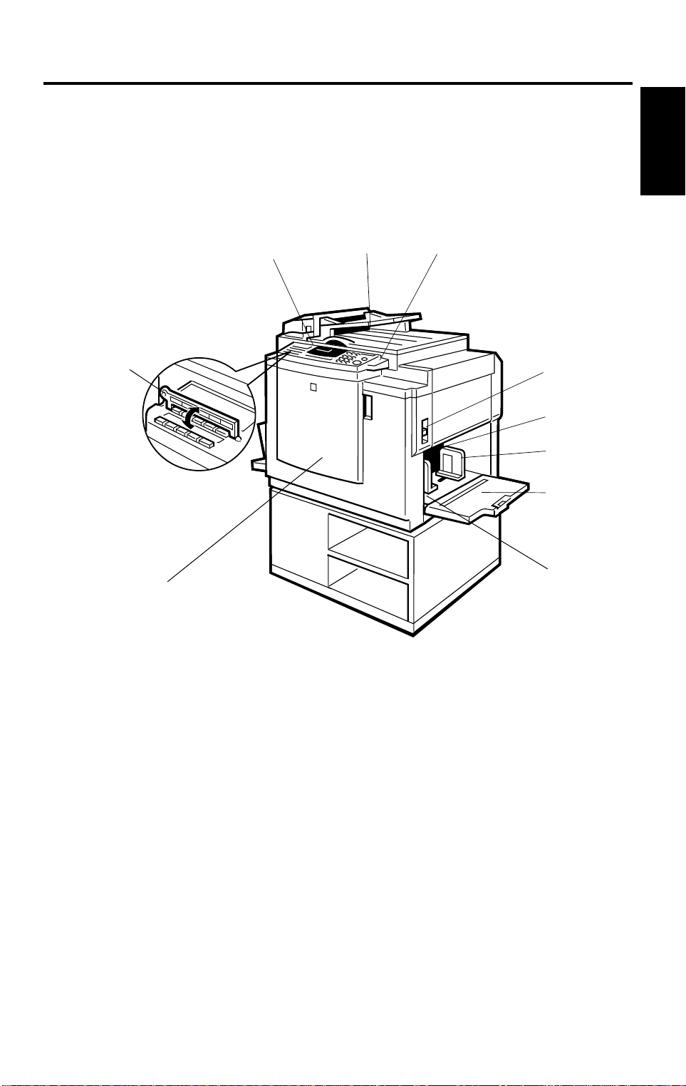
2.1 Machine Exterior
10
9
Overall
Information
1
2
3
4
5
6
7
8
1-17
Page 21

GUIDE TO COMPONENTS AND THEIR FUNCTION: C226 1 November 1996
1. Operation panel
2. Platen cover
3. Original table
release lever
4. Feed roller
pressure lever
5. Separation roller
pressure lever
6. Paper feed side
plates
7. Paper feed table
8. Side plate fine
adjusting dial
9. Front cover
Operator controls and i ndicators are locat ed here.
Lower this cover ove r an original before prin ting.
Use to open the original table unit when installing the master.
Use to adjust the contac t pressure of the paper fee d ro l ler
according to pa per th ickness.
Use to adjust the separa tion roller pressu re to prevent
double feed.
Use to prevent paper sk ew .
Set paper on this table fo r pri nti ng.
Use to shift the pape r feed table sidewa ys .
Open to access to the in side of the machine.
10.Plate
Flip over when you use One Touch Class fu nct ion.
1-18
Page 22
1 November 1996 GUIDE TO COMPONENTS AND THEIR FUNCTION: C226
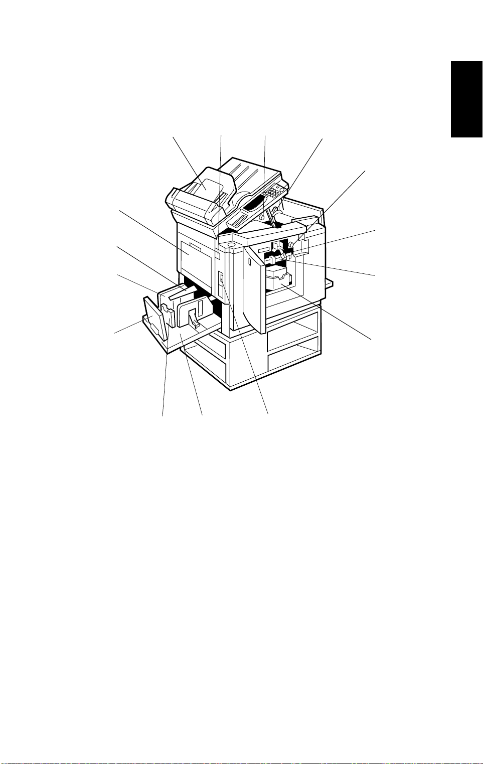
2.2 Machine Interior
1
15
14
23
4
5
6
Overall
Information
13
12
11
10
7
8
9
1-19
Page 23

GUIDE TO COMPONENTS AND THEIR FUNCTION: C226 1 November 1996
1. Document feeder
(Option)
2. Master eject unit
open button
3. Master cut button
4. Pressure release
lever
5. Drum rotation
button
6. Drum unit lock
lever
7. Drum unit
8. Ink holder
9. Main switch
10.Paper delivery table
11.Small size paper
delivery end plate
Original inser ted i nt o th e doc um ent feeder are indivi d ual l y
and automatica ll y fed ont o and removed from t he ex posure
glass.
Press to remove mis fe d pap er or a m isf ed master.
Press this button to cut the m aster leading edge after
installing a new master roll.
Use to install the master roll.
Press to rotate the drum unit.
Lift to unlock and pull out the drum unit.
The master is wrapped around this unit.
Set the ink cartridge in this holder.
Use to turn the power on or of f.
Completed print s ar e deli vered here.
Use to align the leading edge of prints tha t are A4, 8
1/2
" x 11"
or smaller.
12.Paper delivery end
plate
13.Paper delivery side
plate
14.Wing guides
15.Master eject
container cover
Use to align the leading edge of prints larg er tha n A4, 8
1/2
11".
Use to align the prints on the paper delivery table.
When printing on th i n or sm al l size paper, lift these guides.
Open when remov ing t he m aster eject box.
" x
1-20
Page 24

1 November 1996 OPERATION PANEL: C226
3. OPERATION PANEL: C226
3.1 Keys
1
2
4
3
5
6
Overall
Information
7
1. Economy/Tint key
2. Skip Feed key
3. Image Density key
4. Paste Shadow Erase key
5. Auto Cycle key
6. Master Makin g/ Prin t key
Press to select Master Making or Print
mode.
7. Security key
8. Quality Start key
9. SP mode key
10. Edge Erase key
12
8
9
13 14
10 11
15
16
17
18
20
19
21
11. Edge Erase/Center Era se key
12. 13. 14. CS mode key s
15. 16. Scroll keys
Press to select si ze and direction
of paper or original in Edge
Erase/Center Erase and Edge
Erase function.
Press to select the mo de i n
Service Program mode.
17. Type of Original key
18. Reduce key
19. Enlarge key
1-21
Page 25

OPERATION PANEL: C226 1 November 1996
22
28
29
23
20. Full Size key
Press to make full size prints.
21. Combine 2 Orig in al s key
22. Image Position keys
23. Reset key
Press to reset the error indicators.
24. Program Class key
25. Program key
26. Proof key
Press to make proof prints.
27. Clear Modes key
Press to cancel all previously
entered settings.
28. Speed keys
30
24 25
31
27
26
32
33
29. Lower key
Press to lower the paper feed
table.
30. Clear key
Press to change the nu m ber set .
31. Number keys
Press to enter the number of
prints and data.
32. Enter key
Press to input data int o m em ory.
33. Start key
Press t o start ma king of a master
or printing.
34. Stop key
Press to stop the machine
operation.
34
1-22
Page 26

1 November 1996 OPERATION PANEL: C226
3.2 Indicators
1
1. Error indicators
These indicators are lit when a
non-standard condition occurs
within the machine.
2. Guidance Display
Press to stop the machine
operation.
3. Master Making indicator
This indicator is lit when Master
Making mod e is sel ected.
2
3
5
4
4. Print indicator
6
Overall
Information
This indicator is lit when Print
mode is selected.
5. Speed indicators
These indicators show the
printing speed that is selected.
6. Color Drum indicator
This indicator is lit when the
optional colo r drum unit is set.
1-23
Page 27
PRINTING PROCESS 1 November 1996
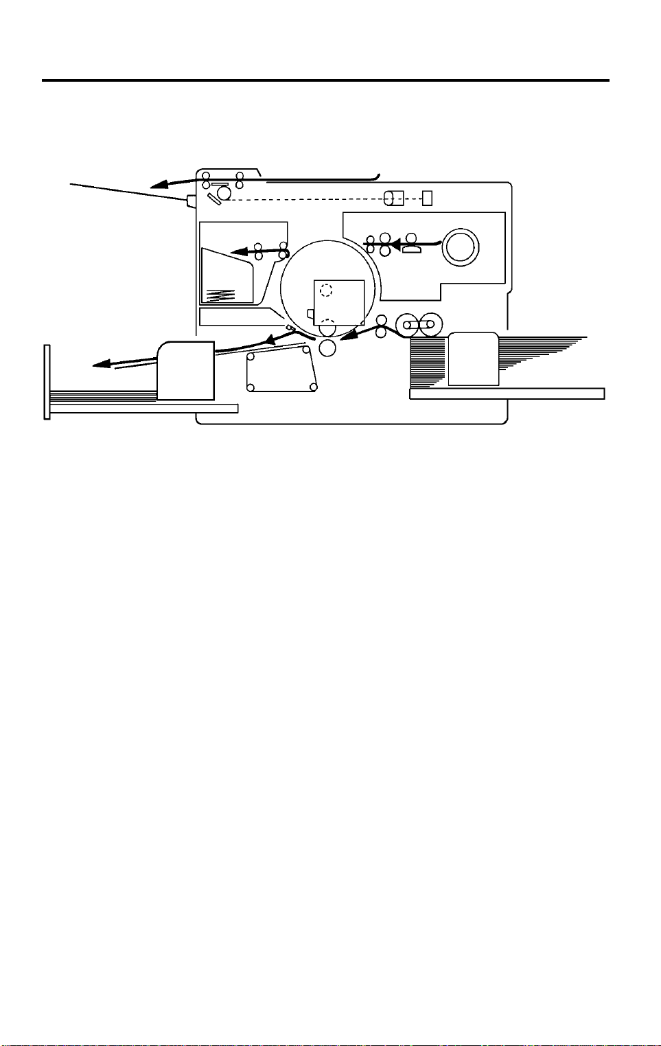
4. PRINTING PROCESS
2
1
6
4
5
1. Master Ejecting: Eject the used master wrapped around the
drum into the master eject box.
2. Scanning: Scan the original image by CCD through the
mirror and the lens while feeding the original.
3
3. Master Feeding: Convert the image signal read by CCD into the
digital signal and send it to the thermal head to
make holes on the surface of the master and
then, set the master around the drum.
4. Paper Feeding: Send paper to the drum section by using center
separation system consisting of the separation
plate and separation roller.
5. Printing: Press the paper fed from the paper feed section
to the drum to transfer the ink through drum
screen and the master.
6. Paper Delivering: Peel the printed paper with the Exit Pawl and
Air knife and eject the paper onto the paper
delivery table.
1-24
Page 28
1 November 1996 ELECTRICAL COMPONENTS LAYOUT
5. ELECTRICAL COMPONENTS LAYOUT
5.1 C226
5.1.1 ADF and Scaner
4
1
17
19
20
Overall
Information
6
9
13
21
22
25
1-25
28
Page 29

ELECTRICAL COMPONENTS LAYOUT 1 November 1996
Table
INDEX
NO.
Printed Circuit Board
1 OPU (Operation Pan el Uni t ) This boar d co nt ro l s the operation panel.
Contact Image Sens or and
Xenon Lamp
9
Motors
6 ADF Motor This stepper motor dri ves the scan ner .
4 Scanner Motor This stepper motor dr ives the book scanner.
Sensors and Switches
Document Sensor This detects the presence of a docu m ent i n th e
17
Scan Line Sensor This detects when a page i s app ro aching the auto
19
20 Not used
ADF Cover Switch This detects whether the ADF cover is open or
21
Scanner Home Positi on
28
Sensor
Platen Cover Sensor This detects wheth er the plat en cover is open or
25
22 ADF Swi t ch This detects whether th e ADF unit i s open or closed.
NAME FUNCTION
This sensor reads an d converts the light reflected
from the document in to an analog video sig nal. It
uses an RMLA (Roof Mi rror Lens Array) sensor un it.
The xenon lamp which illuminates the document is
contained in t his unit .
feeder.
shadi ng posit ion.
closed.
This detects when the image sensor is at home
position.
closed.
Others
13 Lamp Stabilizer This supplies power to the xenon lamp.
1-26
Page 30
1 November 1996 ELECTRICAL COMPONENTS LAYOUT
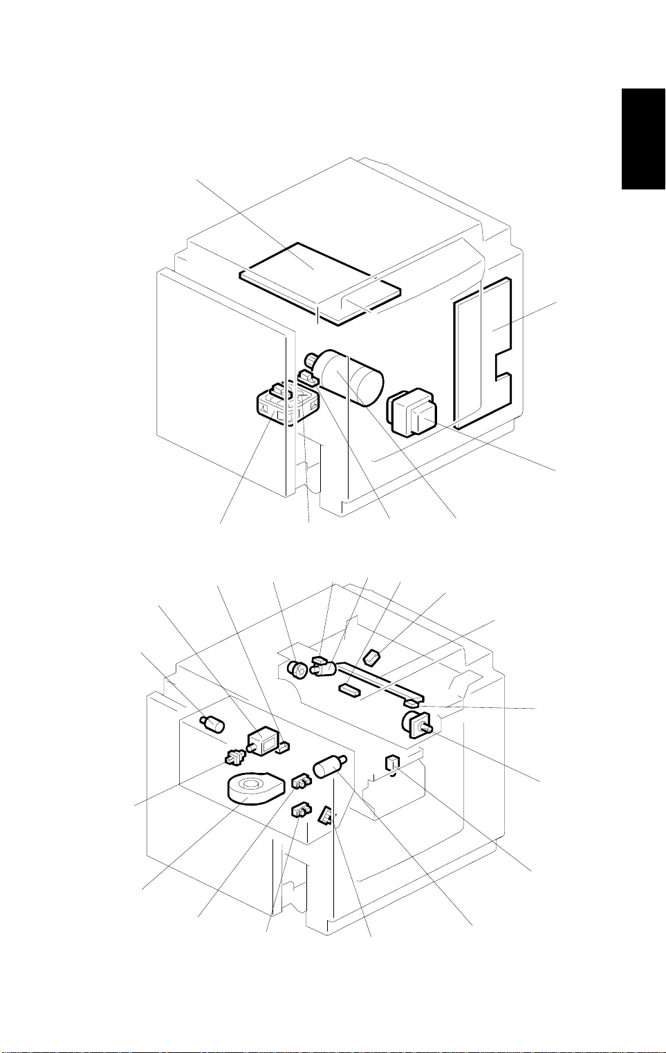
5.1.2 Main Body
39
63
Overall
Information
28
27
26
29
5
30
31
2
1
33
3
34
4
32
35
36
19
20
21
25
24
23
22
1-27
Page 31

ELECTRICAL COMPONENTS LAYOUT 1 November 1996
59
60
14
62
64
65
61
58
54
53
55
52
51
56
57
50
49
48
47
46
45 44
18
37
38
40
41
42
43
1-28
Page 32

1 November 1996 ELECTRICAL COMPONENTS LAYOUT
Table
INDEX
No.
Motors
Main Motor Drives paper feed, drum, printing and paper delivery
1
Vacuum Motor Provides suction so that paper is held f irm ly on the
4
20 Master Fe ed M ot or Feeds the master to the drum.
22 Pressure Pl at e M otor Raises and lower s the pr essure plate.
Air Knife Motor Rotates the fan to provide air to separate the paper
26
28 Master Ejec t Mot or Sends used masters into the mas te r eje ct box.
33 Cutter Motor Cuts the master.
Image Shift Motor Changes the timing bet ween the paper feed roller
60
64 Paper Table Drive Motor Raises and lowers the paper table.
Solenoids
Ink Supply Solenoid Releases the spr ing cl utch to activate the ink supply
21
29 Master Ejec t Solenoid Opens the master clamp to eject the master.
Paper Feed Solenoid Releases the paper feed sector gear to rotate the
51
52 Printing Pr ess ur e Sol enoid Moves the press roller against the drum.
Master Eject Clamper
56
Solenoid
Drum Lock Solenoi d Preven ts removal of the drum unit w hen the drum is
58
Master Feed Clamp er
59
Solenoid
NAME FUNCTION
unit component s.
transport belt.
leading edge from the dru m .
and the drum to adjust the ver t i cal i m age position.
pump.
paper feed roller .
Opens the master cl am p to eject the mast er .
not at the home positi on.
Opens the master cl am p to eject the mast er .
Overall
Information
Switches
Scanner Unit Safety Sw itc h Check w het her the scanner unit is set corre ct l y or
14
Plotter Cover Safety Sw itc h Check whether the co ver on t he plotter unit is closed
18
19 Left Cutter Switch Detects when the cutter position is at the far left.
Master Eject Box Switch Checks whether the master eject box is installed
27
32 Right Cutter Switch Detects when the cutter position is at the far right.
37 Front Doo r Safet y Swi tch Checks whether the front door is set correctly or no t.
38 Drum Safety Switch Checks whether the drum unit is set correctly or not.
Paper Table Safety Switch Checks whether the paper table is opened or not.
41
not.
correctly or not.
correctly or not.
1-29
Page 33

ELECTRICAL COMPONENTS LAYOUT 1 November 1996
INDEX
No.
Test Switch Releases the cover safety functions. (NOTE:)
47
Main Switch Turns the power on or off.
48
Master Eject Unit Safety
49
Switch (220V machines only)
Master Eject Unit Safety
55
Switch (115V machines only)
Master Cutter Switch Informs the CPU to cut the master paper leading
62
65 Drum Rotation Switch Informs the CPU to rotate the main motor at 10 rpm.
Sensors
3 1st Paper Exit Sen sor Detects misfeeds.
5 2nd Paper Exit Sensor Detects misfeeds.
Lower Pressure Plate Sensor Informs the CPU if the pressure plate is at the lower
23
Full Master Box Sensor Informs the CPU if the master eject box is full of
24
NAME FUNCTION
Checks whether the ma st er e ject uni t is cl osed
correctly or not. Cuts the ac power.
edge.
limit position.
used masters.
Upper Pressure Plate Sensor Informs the CPU if the pressure plate is at the upper
25
30 Master Ejec t Sen sor Det ects m aster eject jams.
34 Master Buc kle Sensor Detects master buckling.
Master End Sensor Informs the CPU when the plotter unit runs out of
35
Paper Table Height Sensor Detects when the paper table reaches t he paper
40
Paper Table Low er Limit
42
Sensor
43 Printing Press ur e Sensor Informs the CPU when print ing pr es sur e i s ap pl ied.
Paper End Sensor Informs the CPU when the paper table runs out of
44
50 Drum Rot ati on Sensor Supp l ies t i m ing pulses to the main boar d.
53 2nd Drum Posi ti on Sensor Checks the positi on of th e dr um .
57 1st Drum Posit i on Sensor Checks the position of the drum.
Printed Circuit Board
Main Control PCB Controls all machine functions both directly and
39
limit position.
master roll.
feed position.
Detects when the paper table reach e s the l ow est
position.
paper.
through other boards.
1-30
Page 34

1 November 1996 ELECTRICAL COMPONENTS LAYOUT
INDEX
No.
54 Ink Detection PCB Checks if the ink is present in the drum.
63 Power Suppl y PCB Rectifies 100 V ac input and supplies dc vol tage.
Counters
45 Copy Coun te r Keeps track of the total number of copies made.
46 Maste r Counter Keeps track of the total num ber of ma st er s m ade.
Others
2 Transformer Steps down the wall vol t ag e.
Reverse Roller Clutch Transfers master feed motor rotation to the reverse
31
36 Thermal H ead Burns the image onto the master.
61 Encoder Converts 16 image positions to 4 bit data.
NOTE:
1) The Master Eject Unit Safety Switch in the 220 V machines cannot
NAME FUNCTION
roller at proper timi ng.
be disabled by this test switch.
2) When you use this test switch, be sure to return it to home position
after servicing in order to recover the cover safety functions.
Overall
Information
1-31
Page 35

ELECTRICAL COMPONENTS LAYOUT 1 November 1996
5.2 C224
Electrical Component Layout
14
13
12
11
10
15
16
17
18
1
9
2
8
7
6
5
31
30
29
32
4
33
3
34
35
36
28
19
27
26
25
24
20
21
22
23
1-32
Page 36

1 November 1996 ELECTRICAL COMPONENTS LAYOUT
55
54
53
56
52
51
57
50
58
49
59
48
60
47
61
46 45
62
63
44
64
Overall
Information
65
66
37
38
39
40
41
42
43
1-33
Page 37

ELECTRICAL COMPONENTS LAYOUT 1 November 1996
Table
INDEX
No.
Motors
Main Motor Drives paper feed, drum, printing and paper delivery
1
Vacuum Motor Provides suction so that paper is held f irm ly on the
4
7 ADF Drive Motor Feeds the origin al to the original transp or t se ct i on.
12 Origina l Tra nsport Motor Transports the original to the scanner section.
20 Master Fe ed M ot or Feeds the master to the drum.
22 Pressure Pl at e M otor Raises and lower s the pr essure plate.
Air Knife Motor Rotates the fan to provide air to separate the paper
26
28 Master Ejec t Mot or Sends used masters into the mas te r eje ct box.
33 Cutter Motor Cuts the master.
Image Shift Motor Changes the timing bet ween the paper feed roller
60
64 Paper Table Drive Motor Raises and lowers the paper table.
Solenoids
Original Pressure Solenoid Presses the original pressure plate down on the
11
Ink Supply Solenoid Releases the spr ing cl utch to activate the ink supply
21
29 Master Ejec t Solenoid Opens the master clamp to eject the master.
Paper Feed Solenoid Releases the paper feed sector gear to rotate the
51
52 Printing Pr ess ur e Sol enoid Moves the press roller against the drum.
Master Eject Clamper
56
Solenoid
Drum Lock Solenoi d Preven ts removal of the drum unit w hen the drum is
58
Master Feed Clamp er
59
Solenoid
NAME FUNCTION
unit component s.
transport belt.
leading edge from the dru m .
and the drum to adjust the ver t i cal i m age position.
originals.
pump.
paper feed roller .
Opens the master cl am p to eject the mast er .
not at the home positi on.
Opens the master cl am p to eject the mast er .
Switches
Printing Density Switch Use to select the printing density corresponding to
6
14 ADF Safety Swit ch Check whether the ADF un it is se t co rrectly or not.
Fluorescent Lamp Safety
18
Switch
19 Left Cutter Switch Detects when the cutter position is at the far left.
Master Eject Box Switch Checks whether the master eject box is installed
27
32 Right Cutter Switch Detects when the cutter position is at the far right.
the type and quality of the ori gi n al .
Cuts the power for the fluorescent lamp when the
scanner is opene d.
correctly or not.
1-34
Page 38

1 November 1996 ELECTRICAL COMPONENTS LAYOUT
INDEX
No.
37 Front Doo r Safet y Swi tch Checks whether the front door is set correctly or no t.
38 Drum Safety Switch Checks whether the drum unit is set correctly or not.
41 Paper Table Safety Switch Checks whether the paper table is opened or not.
47 Test Switch Releases the cover safety functions. (NOTE:)
48 Main Switch Turns the power on or off.
Master Eject Unit Safety
49
Switch (220V machines only)
Master Eject Unit Safety
55
Switch (115V machines only)
Master Cutter Switch Informs the CPU to cut the master paper leading
62
65 Drum Rotation Switch Informs the CPU to rotate the main motor at 10 rpm.
Sensors
3 1st Paper Exit Sen sor Detects misfeeds.
5 2nd Paper Exit Sensor Detects misfeeds.
Original Regist r at i on Sen sor Detects misfeeds in the AD F, and synchronizes
9
10 2nd Orig inal Sensor Detects when the original comes to the feed position .
13 1st Original Sensor Detects when the original is set in the ADF mode.
Lower Pressure Plate Sensor Informs the CPU if the pressure plate is at the lower
23
Full Master Box Sensor Informs the CPU if the master eject box is full of
24
Upper Pressure Plate Sensor Informs the CPU if the pressure plate is at the upper
25
30 Master Ejec t Sen sor Det ects m aster eject jams.
34 Master Buc kle Sensor Detects master buckling.
Master End Sensor Informs the CPU when the plotter unit runs out of
35
Paper Table Height Sensor Detects when the paper table reaches t he paper
40
Paper Table Low er Limit
42
Sensor
43 Printing Press ur e Sensor Informs the CPU when print ing pr es sur e i s ap pl ied.
Paper End Sensor Informs the CPU when the paper table runs out of
44
50 Drum Rot ati on Sensor Supp l ies t i m ing pulses to the main boar d.
53 2nd Drum Posi ti on Sensor Checks the positi on of th e dr um .
57 1st Drum Posit i on Sensor Checks the position of the drum.
NAME FUNCTION
Checks whether the ma st er e ject uni t is cl osed
correctly or not. Cuts the ac power.
edge.
master feed with ori gi na l fee d.
limit position.
used masters.
limit position.
master roll.
feed position.
Detects when the paper table reach e s the l ow est
position.
paper.
Overall
Information
Printed Circuit Board
16 CCD PCB Converts light into an electrical signal.
17 A/D Convers i on PCB Converts analog signals into di gital signals.
1-35
Page 39

ELECTRICAL COMPONENTS LAYOUT 1 November 1996
INDEX
No.
Main Control PCB Controls all machine functions both directly and
39
54 Ink Detection PCB Checks if the ink is present in the drum.
63 Power Suppl y PCB Rectifies 100 V ac input and supplies dc vol tage.
Counters
45 Copy Coun te r Keeps track of the total number of copies made.
46 Maste r Counter Keeps track of the total num ber of ma st er s m ade.
Others
2 Transformer Steps down the wall vol t ag e.
8 Fluorescent Lam p Exposes the original.
15 Fluorescent Lamp Stabilizer Controls the exposure lamp.
Reverse Roller Clutch Transfers master feed motor rotation to the reverse
31
36 Thermal H ead Burns the image onto the master.
61 Encoder Converts 16 image positions to 4 bit data.
66 Operation Panel Interfaces the CPU and the oper at or .
NOTE:
1) The Master Eject Unit Safety Switch in the 220 V machines cannot
NAME FUNCTION
through other boards.
roller at proper timi ng.
be disabled by this test switch.
2) When you use this test switch, be sure to return it to home position
after servicing in order to recover the cover safety functions.
1-36
Page 40

1 November 1996 ELECTRICAL COMPONENTS LAYOUT
5.3 C215/C216
Electrical Component Layout
4
3
2
1
5
6
7
8
Overall
Information
9
20
19
10
18
17
16
15
14
13
12
11
36
37
35
38
34
33
32
31
21
22
23
24
25
26
27
28
29
30
1-37
Page 41

ELECTRICAL COMPONENTS LAYOUT 1 November 1996
39
40
41
42
43
44
45
46
65
64
63
62
61
60
59
58
57
56
55
47
48
49
50
51
52
53
54
1-38
Page 42

1 November 1996 ELECTRICAL COMPONENTS LAYOUT
Table
INDEX
No.
Motors
4 Original Transport Motor Transpor ts the original to the scanne r se ct ion.
10 Master Feed Motor Feeds the master to the drum.
11 Cutter Motor Cuts the master.
14 Master Eject Motor Sends used master into the master eject box.
18 ADF Drive Motor (C216) Feeds the original to the scanner section.
Image Shift Motor Changes the tim i ng between the paper fe ed r oll er
25
28 Paper Table Drive Motor Raises and lowers the pape r table.
Main Motor Drives paper feed, drum, printi ng and paper deliv er y
30
Air Knife Motor Rotates the fan to separate the paper leading edge
60
Vacuum Motor Provides suction so paper is held firmly on the
61
Solenoids
Original Pressure Solenoid
3
(C216)
Master Eject Solenoid Moves the master eject ro ll er to co ntact th e dr um
15
Master Eject Clamper
21
Solenoid
Drum Lock Sole noid Prevents remov al of the dru m uni t unl ess the drum is
22
Master Feed Clamper
23
Solenoid
24 Reverse Roller Solenoid Releases the clutch to rotat e t he r eve rs e ro l ler .
Paper Feed Solen oid Releases the paper feed sector gear to rotat e t he
27
32 Printing Pressure Solenoid Moves the press roller against the drum.
Ink Supply Soleno id Releases the spring clutch to activate the ink su ppl y
47
NAME FUNCTION
and the drum to adjust the vertical image position.
unit component s.
from the drum.
transport belt.
Presses the origi nal pr es sur e pl ate down on the
originals.
surface.
Opens the mast er clam p t o eject the master.
at the original st op position
Opens the ma st er clam p t o cl am p the master.
paper feed rolle r.
pump.
Overall
Information
Switches
6 Right Cutter Switc h Detects when the cutte r po sit i on is at th e fa r right .
12 Left Cutter Switch Detects when the cutter position is at the far left.
Master Box Switch Checks whether the master eject box is i ns ta l led
16
Master Eject Unit Safety
36
Switch
Master Cut Switch Informs the CPU to cut the master paper leading
41
correctly or not.
Checks whethe r the M as te r Eject Unit is closed
correctly or not.
edge.
1-39
Page 43

ELECTRICAL COMPONENTS LAYOUT 1 November 1996
INDEX
No.
Scanner Safety Switch Checks whether the scanner unit is closed correctly
42
44 Drum Rotation Switch Informs the CPU to rotate the main motor at 10 rpm.
45 Front Door Safety Switch Checks whether the Front Door is set correctly or not.
46 Drum Safety Switch Checks whethe r the dr um unit is set correctly or no t.
Paper Table Safet y Swi tch Checks whether the paper table is op ened correctly
52
57 Interlock Switch Releases the cover safety func tions.
59 Main Switch Turns the power on or off.
Full Master Detecting Switch Informs the CPU when the master eject box is full of
62
Pressure Plate Positio n
63
Switch
Printing Densit y Swi t ch Us e to sel ec t the pr i nti ng density accord ing t o th e
64
65 ADF Safety Switch (C216) Check whether the ADF unit is set cor r ect l y or not .
Sensors
Original Registration Sensor Informs the CPU when the original lea di ng edge
1
2 2nd Original Sensor Detects when the original is set.
Master End Sensor Informs the CPU when the pl ot ter un i t runs out of
9
13 Master Buckle Sensor Detects master buckles.
Master Eject Sensor Detects when the used master is sent into the
17
19 1st Original Sensor (C216) Detects when the original i s set in the ADF mode.
29 Drum Rotation Sensor Supplies timi ng pulses to the main board.
33 2nd Drum Position Sensor Checks the position of the dru m .
34 1st Paper Exit Sensor Detects misfeed.
35 2nd Paper Exit Sensor Detects misfeed.
37 1st Drum Position Sensor Checks the posi tio n of the dru m .
Paper Table Height Sensor Detects when the paper table rea ches the paper
49
Paper End Sensor Inform s t he CPU when the paper table runs out of
51
Paper Table Lowe r Limi t
53
Sensor
Printing Pressure Sen sor Informs the CPU when the prin tin g pr essure is
54
NAME FUNCTION
or not.
or not.
masters.
Informs the CPU when the pressure plat e has
reached the home position.
type and quality of th e or igi nal.
reaches the exposure glass.
master roll.
master eject box .
feed position.
paper.
Detects when the paper table reaches the lowest
position.
applied.
Printed Circuit Board
7 Power Supply PCB Rectifies 100V AC input and su ppl ies DC voltage.
1-40
Page 44

1 November 1996 ELECTRICAL COMPONENTS LAYOUT
INDEX
No.
31 AC Drive PCB Controls the AC component by relays.
38 Ink Detection PCB Control the ink supply.
39 CCD PCB Converts the light intensity into the electrical signal.
40 A/D Conversion PCB Converts the an al ogue signal into the di gital signal.
Operation Pan el Controls the LED perfor m anc e and monitors the key
43
Main Control PC B Controls all machine func tions both directl y and
48
50 Image Processing PCB Controls the master pr ocessing perform ance.
Counters
55 Copy Counter Keeps track of the tot al num ber of copies made.
56 Master Counter Keeps track of the total numb er of masters made.
Others
Fluorescent Lamp Stabilizer Stabilizes the power supplement to the fluorescent
5
8 Thermal Head Burns the image on to the master.
20 Fluorescent Lamp Exposes the original.
26 Encoder Converts 16 ima ge positions to 4 bit data.
58 Circuit Breaker Cuts the ac line.
NAME FUNCTION
operation.
through other bo ar ds.
lamp.
Overall
Information
1-41
Page 45

ELECTRICAL COMPONENTS LAYOUT 1 November 1996
5.4 C211/C212/C213
Electrical Component Layout
25
24
23
1
22
21
5
3
2
4
6
7
8
9
10
11
12
13
14
20
19
18
16
17
15
1-42
Page 46

1 November 1996 ELECTRICAL COMPONENTS LAYOUT
42
41
26
27
28
29
30
31
Overall
Information
32
33
34
35
36
40
39
37
38
1-43
Page 47

ELECTRICAL COMPONENTS LAYOUT 1 November 1996
71
70
69
72
68
67
66
43
65
64
44
63
62
45
61
46
47
48
49
50
51
52
53
54
55
56
57
58
5960
1-44
Page 48

1 November 1996 ELECTRICAL COMPONENTS LAYOUT
Table
INDEX
No.
Motors
4 Original Transport Motor Transports the original to the scanner secti on.
11 Master Fe ed M ot or Feeds the master to the drum.
16 Cutter Motor Cut the master.
19 Master Eject Motor Sends used master into the mast er eject box.
ADF Drive Motor
23
(C212/C213 onl y)
Image shift Motor Changes the timing between the paper feed
30
36 Paper Table Drive Motor Raises and lowers the paper table.
Main Motor Drives paper feed, drum, printing and paper
38
Air Knife Motor Rotates the fan to separate the pap er leadi ng
66
Vacuum Motor Provides suc tion so paper is held firm l y on t he
67
Solenoids
Original Pressure Solenoid
3
(C212/C213 onl y)
Master Eject Solenoi d Moves the master eject rol ler to cont ac t the dr um
20
26 Master Eject Clamper Soleno i d Opens the master clamp to eject the ma ster .
28 Master Fe ed C lam per Solenoid Opens the master cl am p to clamp the master .
31 Reverse Rol l e r Solenoid Releases the clutch to rotate the rev er se r oll er .
Paper Feed Solenoid Releases the paper feed sector gear to rotate the
35
39 Printing Pr ess ur e Sol enoid Moves the press roller against the dr um .
Ink Supply Solenoid Releases the spring clu tc h to acti vat e the i nk
52
Drum Lock Solenoi d Prevents removal of the drum uni t unl ess the
56
NAME FUNCTION
Feeds the original to the scan ner section.
roller and the drum t o adjust vertical image
position.
delivery unit com ponents.
edge from the drum.
transport belt.
Presses the or i ginal pressure plate down on the
originals.
surface.
paper feed roller .
supply pump.
drum is at the original stop position
(This solenoi d can be used on the C21 2/ C 213).
Overall
Information
Switches
6 Right Cutter Switch Detects when the cutter position is far right.
Left Cutter Switch Detects when the cutter position is far left.
17
Master Box Switch Checks whether the master eject box is installed
21
correctly or not.
1-45
Page 49

ELECTRICAL COMPONENTS LAYOUT 1 November 1996
INDEX
No.
29
45
46
49
50
51
58
Master Eject Unit Safety Switch Checks whether the Master Eject Unit is closed
Master Cut Switch Informs the CPU to cut th e m aster paper leading
Scanner Safety Switch Checks whether the scanner unit is cl os ed
Drum Rotation Switch Informs the CPU to rotate the main motor at 10
Front Door Safety Switch Checks whether the Front Door is set correctly or
Drum Safety Switch Checks whether the drum unit is set correctly or
Paper Table Safety Switch Checks whether the paper table is opened
NAME FUNCTION
correctly or not.
edge.
correctly or not.
rpm.
not.
not.
correctly or not.
63 Interlock Switch Releases the cover safety functions.
65 Main Switch Turns the power on or off.
Full Master Detecting Switch Informs the CPU when the master eject box is
68
Pressure Plate Positi on Switch Informs the CPU when th e pr essure plate has
69
Memory/Class Switch
70
(C212/C213 onl y)
Skip Paper Feed Switch
(C212/C213)
71
Printing Density Switch
(C211)
ADF Safety Switch
72
(C212/C213 onl y)
full of master s.
reached the home position.
Selects Memory or Class mode.
Adjusts paper feed interval to allow time for user
to remove prints.
Use to select the printing density according to
the type and quality of the ori gi n al .
Check whether the ADF unit is set correctly or
not.
Sensors
Original Registration Sensor Informs the CPU when the original leading edge
1
reaches the expos ur e glass.
2 2nd Original Sensor Detects when the original is set.
Master End Sensor Informs the CPU when the plotter unit runs out of
10
Paper Size Detection Sensor 3
12
(C212/C213 onl y)
Paper Size Detection Sensor 2
13
(C212/C213 onl y)
Paper Size Detection Sensor 1
14
(C212/C213 onl y)
master roll.
Detects the size of the paper set on the paper
table.
Detects the size of the paper set on the paper
table.
Detects the size of the paper set on the paper
table.
18 Master Buckle Sensor Detects the master buckle existence.
Master Eject Sensor Detects when the used master is sent into the
22
master eject box.
1-46
Page 50

1 November 1996 ELECTRICAL COMPONENTS LAYOUT
INDEX
No.
1st Original Sensor
24
(C212/C213 onl y)
33 1st Drum Position Sensor Checks the position of th e dr um .
34 2nd Drum Position Sensor Chec ks t he position of the drum .
37 Drum Rotation Sensor Supplies timing pulses to the mai n boar d.
41 1st Paper Exit Sensor Misfeed detector.
42 2nd Paper Exit Sensor Misfeed detector.
Drum Master Detection Sensor
47
(C212/C213 onl y)
Paper Table Height Sensor Detects when the paper tabl e re aches the paper
54
Paper End Sensor Informs the CPU when the paper table runs out
57
Paper Table Lower Lim i t Sensor Detects when the paper table reaches the lowest
59
Printing Pressure Sens or Informs the CPU when th e pr int ing pr essure is
69
Printed Circuit Board
7 Power Supply PCB Rectifies 100V AC in put and supplies DC volt age.
Thermal Head Drive Control
8
PCB
27 Ink Detection PCB Control the ink supply.
40 AC Drive PCB Contr ols t he AC com ponent by relays.
CCD PCB Converts the light intensity into the electrical
43
A/D Conversion PCB Converts the analogue signal into the digital
44
Operation Pane l Controls the LED performance and moni t or s the
48
Main Control PCB Controls all machine functions both directly and
53
55 Image Processing PCB Controls the m aster processing performance.
NAME FUNCTION
Detects when the original is set in the ADF mode.
Checks whether the master is on the drum.
feed position.
of paper.
position.
applied.
Supplies the power to the Thermal Head
according to the sig nal fro m the scanner section.
signal.
signal.
key operation.
through other boards.
Overall
Information
Printed Circuit Board
Paper Size Detection Board
15
(C212/C213 onl y)
Counters
61 Copy Counter Keeps track of the total nu m ber of copi e s m ade.
Master Count er Keeps track of the total num ber of ma st er s made.
62
Detects the size of the paper set on the table.
1-47
Page 51

ELECTRICAL COMPONENTS LAYOUT 1 November 1996
INDEX
No.
Others
Fluorescent Lamp Stabilizer Stabilizes the power supplement to the
5
9 Thermal Head Plots the m ast er w ith heat .
25 Fluorescent Lamp Applies light to the orig i nal f or exposure.
32 Encoder Converts 16 image positions to 4 bit data.
64 Circuit Breaker C ut s th e ac li ne off.
NAME FUNCTION
Fluorescent Lamp.
1-48
Page 52

1 November 1996 MECHANICAL COMPONENT LAYOUT
6. MECHANICAL COMPONENT LAYOUT
6.1 ADF AND SCANNER: C226 ONLY
43
2
No. Name Description
Scanner Contains a contact image sensor and a xenon lamp
1
2 R1 Roller Feed s the document throug h the scanner.
3 R0 Roller Feed s the document into the sc anner.
Separation roller Prevents more t han one sheet from feed i ng int o t he
4
5 Document Feed Roller Feeds the document into the scanner.
Pick-up Roller Picks up pages of the docu m ent from t he document
6
7 R2 Roller Feed s the document throug h the scanner.
Platen Cover This covers the original w hich was placed on the
8
9 Exposure Glass Book scanner reads the original on it.
6
5
7
8
9
1
driver.
scanner.
table one at a time.
exposure gla ss.
Overall
Information
1-49
Page 53

MECHANICAL COMPONENT LAYOUT 1 November 1996
6.2 MECHANICAL COMPONENT LAYOUT
18
19
20
21
22
23
24
17 16 15 1413 109 8 7 6 5 4 3
1211
333231302928272625
2
1
38
37
36
35
34
1-50
Page 54

1 November 1996 MECHANICAL COMPONENT LAYOUT
1. Thermal Head
2. Platen Roller
3. Master Feed Roller
4. CCD (Except for C226)
5. Lens (Except for C226)
6. Reverse Roller
7. Ink Roller
8. Drum Unit
9. 1st Eject Roller
10. 2nd Eject Roller
11. Original Pressure Plate
(C212/C213/C216/C224)
12. Pull-out Roller
(C212/C213/C216/C224)
13. Separation Blade
(C212/C213/C216/C224)
14. Original Feed Roller
(C212/C213/C216/C224)
15. 1st Original Transport Roller
(Except for C226)
16. Exposure Grass
(Except for C226)
17. 2nd Original Transport Roller
(Except for C226)
18. Fluorescent Lamp
(Except for C226)
19. Original Exit Tray
(Except for C226)
20. Feed Sub Mirror
(Except for C226)
21. Mirror
22. Master Eject Box
23. Exit Pawl
24. Air Knife
25. Delivery Table
26. Delivery Guide Plate
27. Vacuum Unit
28. Press Roller
29. Doctor Roller
30. 2nd Feed Roller
31. Lower Separation Roller
32. Separation Plate
33. Paper Feed Side Plate
34. Paper Feed Table
35. Paper Feed Roller
36. Upper Separation Roller
37. Ink Holder
38. Master Spool
Overall
Information
1-51
Page 55

DIFFERENCES BETWEEN MODELS 1 November 1996
7. DIFFERENCES BETWEEN MODELS
7.1 C226 AND C224
No. Item Remarks
These units are commonly used in our facsimile products.
The C226 model use s a book type scanner. Th e C 224
model does not have this feature. The contact image
sensor remove s th e necessity of compl i cated adjustment s
1.
ADF, Scanner, and
Operation Pan el
needed for a CCD scanner.
A half-tone processor is used for image processing. This
processor is similar to those in higher level models. It
produces better co py quality half-tone i m ag es i n Photo
and Letter/Photo modes.
[A]
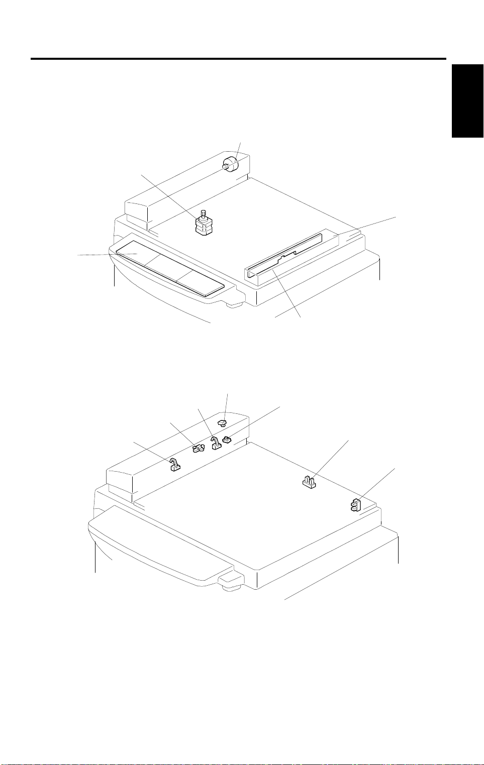
2. Paper Deli v er y Table
[B]
The C226 model use s a new paper delivery tabl e. This
table has newly added small guide plates [A] on each
front and rear side fenc e. The guide plates stack the
prints more evenly. The small guide plat es [B] , on the
bottom of each side fence keep the prints ali gned in the
center of the table while the copies are stacked.
Also, the paper stack ca pacity has been incre ased from
500 sheets to 1000 sheets.
[C]
Due to the the new paper del ivery table design, a new
auxiliary bracket [C] has been added for optional TAPE
MAKER installation. For details, refer to the "Tape Maker
Installation" section.
1-52
Page 56

1 November 1996 DIFFERENCES BETWEEN MODELS
No. Item Remarks
NOTE:
1) The small uppe r gu ide pl atesare needed w hen thin or
normal paper (80g/ m
2
or 20 lb. and thinner paper) is
used. The guide pla te is not needed for thicker pap er . If
the paper is too thick, it may be caught by the upper
guide plates. (Thick paper can be stacke d evenly
without the upper gui de plates.)
2) When the small up per gui d e pl at es are used, the paper
delivery table’s stack capacity reduces to about 750
sheets (dependin g on paper type). Close t he guide
plates to achieve th e maximum paper stack capacity.
3) The optional TAPE MAKER works with up to 500
sheets (dependin g on paper type).
Overall
Information
3. Main Control PCB
The C224 model’s A/D Co nve rs ion PC B is not used. The
function is now included in the Main Control PCB, which
is located beneath t he sc anner unit. Since the M ain
Control PCB was move d from t he op er at i onal side, the
Power Supply PCB was also moved from the
non-operation side of th e m achine to where the Main
Control PCB was located in the C224 model.
1-53
Page 57

DIFFERENCES BETWEEN MODELS 1 November 1996
No. Item Remarks
The following func tions were not used in the C 224 model:
– CS Mode
– SP Mode (User Accessible)
– Paste Shadow Erase Mod e (Unique to the C226
model)
– One Touch Clas s M ode (Uni que to the C226 model)
– Tint Mode (Unique to the C226 model)
– Program Mode
– Letter/Photo Mo de ( In addi ti on to the Letter and
Photo modes.)
– Quality Start Mode: See NOTE 1
4.
New Functions in
Operation
– Edge Erase Mode: See NO TE 2
– Edge Erase / Center Erase Mod e: See NO TE 2
NOTE:
1) In the Quality Start mo de, afte r the m aster making
process, one extra print (this can be set by the
operator from 0 to 3 print s) is m ade at the lowest
printing speed (20 cpm ) . Th e tri al pr i nt is m ade in the
same way as other models. As the default se tting, two
extra prints are made in the Quality Start m ode. The
Quality Start mode i s also used in some othe r models,
however, this meth od is unique to the C226 m odel.
2) In other models which use a book type sca nne r,
shadows near the edg es and the center of print s (wit h
the platen cover open) can be removed. In the C226, a
similar function is available as the Edge Erase/Center
Erase mode. Before using this fun cti on, th e pr int paper
size must be selected manually by the operator. Also.
the erasable margin widths for the edges and center
adjustable with a us er accessible SP mode.
The Edge Erase mode is t he sa m e as t he M ar gi n
Erase mode used in some other models that have a
book type scanner .
1-54
Page 58

1 November 1996 DIFFERENCES BETWEEN MODELS
7.2 BETWEEN C224 AND C211/C212/C213
No. Item Remarks
A CCD which corresponds to 300 dpi pixel density is used.
1. CCD
Number of Effective
Pixels:
Reading Lengt h: 309 mm
Photo Signal Storage: 2.5 ms
The thermal he ad and thermal head dr i ve cir cuit have
been changed corresponding to the 300 dpi pixel density
and the increased master feed speed.
3648 pixels
Overall
Information
2. Thermal Head
3.
Drum Ink Roller
Layout
Density of thermal
heating element s
Number of thermal
heating element s
Memory length 256 mm
To ensure paper separation from the drum , th e ink r ol l er
has been shifted towards the pap er feed table.
The distance L has be en changed from 5.0 mm t o 3. 5 m m
(same as the C21 6 m ode l ).
C211 model
[A]
L
L = 5.0 mm L’ = 3. 5 m m
NOTE:
The optional color dr um fo r the C224 model
is commonly used f or the C211 m odel.
(The distance L for th e color drum is
4.5 mm.)
[B]
300 dots/inch
3072 dots
C224 mode
l
[A]
[B]
L’
1-55
Page 59

DIFFERENCES BETWEEN MODELS 1 November 1996
No. Item Remarks
To ensure drum connection, a drum lo ck lever has been
added inside th e front door. To remove t he dr um fro m the
machine, the dru m rele ase lever must be pul l ed up to
disconnect the drum connector. (Same as the C216
model.)
4. Drum Connector
The location of th e i nk de te ct i on bo ar d has been changed
5. Ink Detecti on Board
6. Drum Shaft
7. Exit Pawl Air Pump
Main Board and
8.
9. Thermal Head Drive
12.
13. Air Knife Motor
14.
Image Processing
Board
Paper Table Drive
Motor
Pressure Plate
Position Sensors
from the upper si de to th e right side of the drum shaft. The
ink type switch (SW901), which was not used (always set
at oil type), has been removed. (Same as the C216 model.)
To supply ink to the i nk roller evenly , the second ink suppl y
hole (count from the front side) of the drum sh af t is
covered with a strip of tape.
(Same as the C216 mo del .)
To ensure paper separation from the drum , th e exit paw l
air pump system is standardized. (Same as the C216
model.) (Th e pum p system can opti onally be instal led in
models of the C21 1 ser i es .)
The main board and the image processing board have
been combin ed int o one board.
The thermal he ad dr i ve boar d has been remove d. The
function of the boa rd has been moved to the mai n board.
The thermal he ad voltage is directly appl ied from the
power supply un i t. The ma i n board applies the signal to the
PSU to supply thermal head voltage only dur i ng the master
making process. (Same as the C216 model.)
The paper table dr i ve mo to r ha s been changed from an ac
motor to a dc motor.
The air knife mot or has been changed from an ac mo to r to
a dc motor.
The pressure plate position swi tch and the full master
detecting swi tch have been elimina te d.
Three photo-i nt er ru pt er s, upper and lower press ur e pl ate
sensors and full m aster box sensor ar e used instead.
1-56
Page 60

1 November 1996 DIFFERENCES BETWEEN MODELS
No. Item Remarks
The master eje ct mo to r whi c h had two functions: (one i s t o
15.
16 Skip Feed
17.
18.
Pressure Plate
Motor
Economy Function
(New Function )
Security Mode
(New Function )
drive the exit rollers, the other is to drive the pressure
plate) has been replaced by two motors; the master eject
motor and press ur e pl ate m ot or . Du e to this modification ,
the master box capacity has be en increased.
A user can select from 2 t o 9 ro ta tio ns of th e dr um w hil e
one sheet of pape r is fed.
If "Economy mode" is selected on th e ope ration panel, a
lower thermal head energy is applied when a master is
made. As a result, the image will be lighter than normal
and ink consumption will be less.
"Secret mode" can be selected by changing DIP SW103-6.
If this mode is select ed, the Print key is disabled after
turning the m ai n swi t ch off and on. (Only the "M ast er
making key" is available.)
Overall
Information
1-57
Page 61

DIFFERENCES BETWEEN MODELS 1 November 1996
7.3 BETWEEN C215/C216 AND C211/C212/C213
No. Iter Remarks
The pixel densi t y of the C2 15/ C216 model is 300
dots/inch. Corresponding to this, the CCD used on the
C215/C216 model is the same as the one used on the
C201 model.
1. CCD
2. Thermal Head
Due to pixel density change, the thermal head has been
changed.
Number of effect ive
Pixels:
Reading Length: 309 mm
Photo Signal Storage: 5 ms
Density of thermal
heating element s
Number of thermal
heating element s
Memory length 256 mm
Applied voltage 19~24 V
3648pixels
300 dots/inch
3072 dots
3.
Drum Ink Roller
Layout
To ensure paper separation from the drum , th e ink r ol l er
has been shifted forw ar d t he paper feed table.
The distance L has be en changed from 5.0 mm t o 3. 5 m m .
C211 model
[A]
[B]
L
L = 5.0 mm L’ = 3.5 mm
NOTE:
The optional color dr um fo r the C215/C216 model
is commonly use d fo r t he C211 model.
(The distance L of the color drum is
4.5 mm)
C215/C216 model
[A]
[B]
L’
1-58
Page 62

1 November 1996 DIFFERENCES BETWEEN MODELS
To ensure drum connection, a drum lock lever is added
inside the front door. To remove the dr um from the
machine, the dru m rele ase lever must be pul l ed up to
discon nect th e drum con nector.
4. Drum Connector
The location of th e i nk de te ct i on bo ar d has been changed
5. Ink Detecti on Board
6. Drum Shaft
7. Exit Pawl Air Pump
8. Thermal Head Drive
from the upper si de to th e right side of the drum shaft. The
ink type switch (SW901), which was not used (always set
at oil type), has been removed.
To supply ink to the i nk roller evenly , the second ink suppl y
hole (count from the front side) of the drum sh af t is
covered with a strip of tape.
To ensure paper separation from the drum , th e exit paw l
air pump system is standardized. (The pump system can
optionally be installed on the C211/ C 212/C213 models .)
The thermal he ad dr i ve boar d has been remove d. The
function of the boa rd has been moved to the im age
processing boar d and the main boar d.
The thermal he ad voltage is directly appl ied from the
power supply unit. The main board applies signal to the
PSU to supply thermal head voltage only dur i ng the master
making process.
Overall
Information
1-59
Page 63

DIFFERENCES BETWEEN MODELS 1 November 1996
7.4 BETWEEN C207/C208 AND C211/C212/C213
No. Item Remarks
The heating elements used in the C211/C212/C213 ther m al head
are smaller tha n those used on the C207/C208 models. This
reduces ink set-off on the back sides of copies.
C207/C208 model
1
2
3
4Exterior
5
6
7
Thermal
Head
Thermal
Head Drive
Board
Power
Supply Board
Image
Processing
Board
Main
Harness
Drum Master
Sensor
The thermal hea d dr ive voltage has been decreased from 24 V to
16V because the sm all er heating element s in th e th er m al head
require less power.
The power supply boar d has been modified to output 16V to drive
the thermal head.
An ON/OFF switching circuit for the thermal head drive voltage
(VHD) has been add ed t o th e power supply board.
The design of the fron t co ver and the model name pr i nt ed on the
cover have been changed. This was done for marketing rea sons
and to ensure that the us er s do not confuse the C211/ C 21 2/ C 213
models with the C207/C208 models and use the wrong mast er ty pe.
(The new master is more sensitive.)
The C213 make-up control board has been eliminated because the
C213 image pro ces si ng boar d performs the Mak e- up function.
A VHD ON/OFF line has been added to the main har ness.
The drum master sensor has been chan ged to stabilize the sensor
sensitivity.
C211/C212/C213
model
1-60
Page 64

1 November 1996 DIFFERENCES BETWEEN MODELS
No. Item Remarks
The paper feed rol ler cam has been slightly modified as shown to
reduce the paper speed to 55% that of the C20 7/ C208 models.
(Extended outwa rd at po int [A].) Thi s reduces the nois e cau sed
when the paper leadi ng edge strikes the second feed roller .
Overall
Information
8
Paper Feed
Roller Cam
C207/C208 cam
C211/C212/C213 cam
[A]
The second feed cam has been modified sl ight l y as show n to
reduce the speed of the second feed roller to 40% that of the
C207/C208 model s. (Extended outwa rd at po int [A], moved in at
point [B].) This reduces the noise caused when the second fe ed
rollers turn and the paper [C] snaps as it is pull ed t aut .
[C]
9
Second
Feed Roller
Cam
C207/C208 cam
1-61
C211/C212/C213 cam
[A]
[B]
Page 65

DIFFERENCES BETWEEN MODELS 1 November 1996
No. Item Remarks
The shape of the C211 /C212/C213 press ur e cam has been modified
slightly as sh own t o decrease the pre ssure roller speed to 70% that
of the C207/C208 models. (A portion at po i nt [A] has be en shaved
off.) This reduces th e noi s e caused when the pres sur e r ol ler m oves
against the drum.
C207/C208 cam
10
Pressure
Cam
C211/C212/C2 13 cam
[A]
Rear Paper
Delivery
Side Plate
One of the air slots [B] cu t in t he r ear pap er del i ve ry side pl ate has
been enlarged so that tap e st rip s from t he optional tape dispenser
can be inserted thro ugh it.
C207/C208
11
12
Main Control
Board
C211/C212/C213
[B]
An ON/OFF control circ ui t for the th er m al head drive voltage (V HD )
has been added to th e m ain control board.
The drum master det ection circuit on the m ai n cont r ol boa rd has
been modified to accommodate the new drum master sensor.
1-62
Page 66

1 November 1996 DIFFERENCES BETWEEN MODELS
No. Item Remarks
The 40 cpm print sp eed at each step has been el im i nated on the
C211/C212/C213 models. This reduces ink set-off, which is most
likely to occu r at l ow printing speed s.
C207/C208 C211/ C 21 2/ C 213
Step 1: 40 sheets/min. 60 sheets/min.
Step 2: 60 sheets/min. 75 sheets/min.
Step 3: 80 sheets/min. 90 sheets/min.
Step 4: 100 sheets/min. 105 sheets/mi n.
Step 5: 120 sheets/min. 120 sheets/min.
When the Master Ma king key is pressed, the pr int speed gradually
increases until it reaches the set speed.
Trial Print 1st Print 2nd Print 3rd Print
C207/C208 10 rpm 40 xrpm 60 rpm 80 rpm
C211/C212/
C213
10 rpm 60 rpm 75 rpm 90 rpm
13
Printing
Speed
Overall
Information
14
Thermal
Head
Mounting
Plate
To prevent service personnel from mistakenly installing the
C207/C208 thermal head on C211/C212/C213 mode ls and vice
versa, the distance between the screw holes on each mounting plate
is different.
C207/C208
268 mm
C211/C212/C213
260 mm
1-63
Page 67

DIFFERENCES BETWEEN MODELS 1 November 1996
No. Item Remarks
To prevent users from installing old masters on C211/C212/C213
modes, the diameter of each master spool [A] and master spool
holder [B] has been changed as follows:
C207/C208
[A][B]
50
20
φ
20
φ
φ
15
Master
Spool/
Holder
C211/C212/C 213
New Master - M
(for C211 B4/C212/ C 213)
50
φ
46
φ
46
φ
25
[A]
φ
[B]
25
NOTE:
The C211 LG or C211 A4 m odel’s spool is the sam e diameter as the
C207/C208 spoo l ; how ever, the old master is too w ide to fit on the
C211 LG or C211 A4 mod el ’ s sp ool holder.
Old Master
φ
280 mm
New Mster - S
(for C211 LG/C21 1 A4)
1-64
280 mm
240 mm
50
φ
Page 68

1 November 1996 DIFFERENCES BETWEEN MODELS
No. Item Remarks
A guard [A] has been mou nt ed on the cutter unit [B] to prevent
contact with the cut ter ed ge ( sharp) during cutter uni t removal or
installation.
[B]
Overall
Information
16
Cutter
Section
[A]
Counter rollers [C] have been added to prevent new masters from
creasing as they are being fed through the master re ver se section.
Also, the reverse ro ll er [D] has been modified as shown.
17
Master Feed
Unit
[C]
[D]
1-65
Page 69

DIFFERENCES BETWEEN MODELS 1 November 1996
No. Item Remarks
Both ends of the metal scr een [A] pass through a half etc hing
process. The half et ch ar ea [B] is thinner than the other areas. This
improves the ou ter po rti on of the copy image.
[A]
[B]
The outer drum screen consists of two tetr on screens[C] that reduce
ink set-off.
18 Drum Unit
[C]
The diameter of th e lef t drum l oc k pi n [D ] an d th e rig ht dru m lo ck pin
[E] is different for each dr um t ype as follows:
[E]
[D]
Color Drum Left [D] Right [E]
M: (B4 Size)
S: (A4 Size)
LG: (LG Size)
8
10
10
φ
φ
φ
8
7.6f
7.6
φ
φ
1-66
Page 70

1 November 1996 DIFFERENCES BETWEEN MODELS
No. Item Remarks
The sponge cush ions [A] that were affixed to the pa per del i v er y end
plate have been removed to prevent paper sheets from bouncing
back when they strike the paper deli v ery end plate.
[A]
Paper
19
Delivery End
Plate
Two different siz es of pr essure rollers are used because the pri nt ing
area in the horizontal direction [B] on the C211 LG or C211 A4
model is narrower.
Overall
Information
20
21
Pressure
Roller
Pressure
Cam
B4 size: 292 mm
A4/LG size: 226 mm
[B]
Two different type s of pre ssu re cam s ar e used because the pri nti ng
area (feed direct ion) of A4 copi e s on t he C 21 1 A4 m odel is smaller.
B4/LG Size Pressure Cam
A4 Size Pressure Cam
1-67
Page 71

DIFFERENCES BETWEEN MODELS 1 November 1996
No. Item Remarks
The platen roller [A] has been changed to an electrically conductive
type to prevent the mast er from w r apping around the pla te n ro l ler .
22 Platen Roller
[A]
1-68
Page 72

SECTION 2
SECTIONAL DESCRIPTION
Page 73

1 November 1996 ORIGINAL FEED SECTION
1. ORIGINAL FEED SECTION
1.1 ADF AND SCANNER: C226 ONLY
1.1.1 Book Scanner Overview
[C]
[A]
[D]
[E]
[B]
[I]
[H]
Detailed
Descriptions
The scanner motor [A] drives the scanner [B] through the timing belt [C] and
drive wire [D]. The shaft [E] guides scanner movement in the sub-scan
direction. Inside the scanner [B] are a contact image sensor (containing a
sensor element and xenon lamp) and a xenon lamp driver.
The scanner [B] consists of a contact image sensor and a xenon lamp driver.
The scanner home position sensor [H] allows the scanner return to the same
position after scanning.
The platen cover switch [I] detects if the cover is opened or not.
2-1
Page 74

ORIGINAL FEED SECTION 1 November 1996
1.1.2 ADF Overview
[D]
[E]
[C]
[H]
[B]
[G]
[A]
[F]
The sheet through type ADF feeds the document from the top page of the
document stack on the table.
The pick-up [A] and feed roller [B] feed the original into the scanner, and the
separation roller [C] helps to feed one sheet at a time. Then, the R0 [D], R1
[E], and R2 [F] rollers feed the document through the scanner.
At the time of scanning the document, the scanner moves down to the
scanning position under the exposure glass [G]. The shading plate [H]
pushes the document to the exposure glass at the scan line, so that the
document is within the image sensor’s range of focus.
After scanning, the ADF feeds out the document onto the platen cover, and
the scanner moves back to its home position at the right end of the scanner.
2-2
Page 75

1 November 1996 ORIGINAL FEED SECTION
[B]
[A]
Detailed
Descriptions
The document sensor [A] detects documents when they are set in the ADF.
The sensor [B] is not used although it exists to use this unit for another
product commonly.
2-3
Page 76

ORIGINAL FEED SECTION 1 November 1996
1.1.3 Contact Image Sensor
[A]
[B]
[F]
[E]
[D]
[C]
The contact image sensor (CIS) assembly [A] consists of an exposure glass
[B], a roof mirror lens array [C], a xenon lamp [D], and an image sensor [E].
The CIS moves under the exposure glass when scanning a book original, or
stays at the ADF scan line when scanning a sheet original using the ADF.
The image sensor is a row of 4096 photosensitive elements (B4 width x 16
dots/mm). The roof mirror lens array focuses the light reflected from the
document onto the image sensor.
Because of the short optical path inside the CIS, the focal depth is much
shorter than for a CCD type scanner. Because of this, two springs at each
end of the CIS push it against the exposure glass [F], so that the distance
from the original is kept the same all the time. However in book scanning
mode, if the original is out of the CIS’s focal range, the scanned image may
get darker.
Because the analog output signal is a sawtooth waveform, data sampling
timing should be adjusted whenever a new CIS is installed in the machine.
2-4
Page 77

1 November 1996 ORIGINAL FEED SECTION
1.1.4 Drive Mechanism
1. Book Scanner
[D]
[E]
[C]
[A]
[G]
[B]
[F]
The book scanner motor [A] drives the scanner [B] through the timing belt [C]
and drive wire [D]. The scanner moves along the guide shaft [E].
The spring [F] pushes up the contact image sensor [G] to the exposure glass,
so that the distance from the image sensor to the exposure glass surface is
constant during scanning.
Detailed
Descriptions
2-5
Page 78

ORIGINAL FEED SECTION 1 November 1996
2. ADF
[E]
[C]
[A]
[F]
[B]
[D]
The ADF motor [A] drives the pick-up roller [B], the feed roller [C], the R0
roller [D], the R1 roller [E], and the R2 roller [F].
2-6
Page 79

1 November 1996 ORIGINAL FEED SECTION
1.1.5 Pick-up and Feed (ADF)
[B]
[A]
When the ADF motor starts, the mechanical clutch [A] moves the pick-up
roller [B] down to the document. Then, the machine feeds the top page of the
document. After the last page is scanned, the ADF motor reverses briefly to
move the pick-up roller back to the standby position.
Detailed
Descriptions
1.1.6 Separation Mechanism (ADF)
[A]
[B]
The feed roller [A] and the separation roller [B] prevent more than one sheet
of paper from feeding into the scanner at once.
When the feed roller feeds a sheet of paper, both the feed and the separation
rollers rotate in the feed-in direction. However, if two or more sheets are
between these rollers, the separation roller rotates in the feed-out direction to
prevent the lower sheet from being fed into the scanner.
2-7
Page 80

ORIGINAL FEED SECTION 1 November 1996
1.1.7 Error Conditions
1. Book Scanner
The main cpu detects an error (Error Code E-13 is displayed) if one of the
following conditions occurs.
Condition Description Error Code
The scanner home position sensor did not turn on
after the motor move d fo r mor e t han 7 seconds
Incorrect home posi t i on
sensor conditi on
back to the home posit i on af ter scanning.
The scanner could not l eav e th e hom e position
within 4 seconds of power on. O th er wi se, w hen the
scanner could no t r et ur n to the hom e position withi n
2 seconds of leaving.
E-13
2. ADF
"Paper feed jam" is displayed if one of the following conditions occurs.
Jam Condition Description
Non-feed
Misfeed 1
Misfeed 2
The scan line se nsor does not switch o n wi th i n
5 seconds of the ADF m otor sta rti ng .
The scan line sensor does not turn off after turni ng on even
when the trial print is m ade (when the printing pr essure
sensor is actuat ed) .
When the final page of the document has been fed out of the
scanner, or when a jammed document has been removed,
the ADF motor reverses. The message is di splayed if the
document sens or stays on at this time.
2-8
Page 81

1 November 1996 ORIGINAL FEED SECTION
1.2 OVERALL: C212/C213/C216/C224
[I] [G] [E] [B] [A]
Detailed
Descriptions
[J] [K] [L] [D] [C]
[F][H]
[J]: 2nd Original Transport Rollers
[K]: E xposure Glass
[L]: Fluorescent Lamp
There are two original feed modes in this model.
ADF Mode: The originals [I] set on the original table are detected by the
1st original sensor [A]. When the Master Making key is
pressed, the original pressure plate [B] presses the originals
down. The pull-out roller [C] starts moving the lowest original
forward at the same time. The lowest original is separated
from the other originals by the original feed roller [D] and the
separation blade [E]. When the 2nd original sensor [F]
detects the original, the 1st original transport rollers [G] start
rotating. The rollers stop after the original activates the
original registration sensor [H]. The 1st original transport
rollers start rotating again after the drum section completes
the preparation for the master making.
SADF Mode: The separation blade [E] is released in the SADF mode. The
original on the original table is fed to the starting position
when the 2nd original sensor [F] detects the original.
2-9
Page 82

ORIGINAL FEED SECTION 1 November 1996
1.3 OVERALL: C211/C215
[I] [G]
[J] [K] [L] [H] [F]
[J]: 2nd Original Transport Rollers
[K]: E xposure Glass
[L]: Fluorescent Lamp
[H]: Original Registration Sensor
The original [I] set on the original table is detected by the 2nd original sensor
[F]. At the same time, the 1st original transport rollers [G] and 2nd original
transport rollers [J] start rotating and feed the original to the original start
position where is 12 mm far from the guide plate. The original transport
rollers start rotating again after the drum section completes the preparation
for the master making.
2-10
Page 83

1 November 1996 ORIGINAL FEED SECTION
1.4 ORIGINAL FEED DRIVE MECHANISM:
C212/C213/C216/C224
[J]
[A]
[B]
Detailed
Descriptions
[H]
(f)
(e)
[I]
[C]
(c)(d)
(b)
(a)
[G]
[D]
[E]
[F]
[J] [D]
The original transport rollers [A] are driven by the original transport motor [B],
which is a stepper motor. The original feed rollers [J] are driven by the ADF
drive motor [C] through a series of gears [(a) to (f)]. The ADF drive motor is a
dc motor. The pull-out rollers [D] are driven by the ADF motor through a drive
belt [E].
The original pressure plate [F] is pressed down on the originals by the
original pressure solenoid [G]. The separation blade [H] is moved up and
down by the ADF ON/OFF select switch [I].
2-11
Page 84

ORIGINAL FEED SECTION 1 November 1996
1.5 ORIGINAL FEED DRIVE MECHANISM: C211/C215
[H]
[I]
[F]
[G]
[A]
[B]
[E]
[D]
[C]
When the actuator [A] is pressed down by the original, the 2nd original
sensor [B] is activated and the original transport motor [C] starts rotating. The
rotation of the original transport motor is transmitted to belts [D] and [E] to
turn the lower first original transport roller and lower second original transport
roller. At the same time, both the upper original transport rollers [F] contact
the first and second lower original transport rollers due to pressure from the
springs [G]. The rollers rotate and the original is fed.
When the actuator [H] is pressed down by the original, the original
registration sensor [I] is activated and the original transport motor stops.
When the Master Making key is pressed, the original transport motor rotates
to read the original after the master eject process is finished.
The distance between the sensors is 50 millimeters. If the original registration
sensor is not activated within five seconds, "A" and
indications blink.
2-12
Page 85

1 November 1996 ORIGINAL FEED SECTION
1.6 ELECTRICAL TIMING: C212/C213/C216/C224
(One Original):
2nd Drum Position Sen sor
Master Making Key
1st Original Sensor
Fluorescent Lamp
ADF Drive Motor
Original Pressure Solenoid
2nd Original Sens or
Original Regis trati on Sensor
Original Transport Motor
Master Feed Motor
Read Command
Insert Original
425 ms
Drum
Rotates
120°
Original Feeds 25 mm
Original
Feeds 14 mm
Master Feeds 438 mm
Detailed
Descriptions
T4:
Exposure Glass
12 mm
Original Stop Positio n
Scanning Position
16 mm
Original
Guide Plate
T1: When originals are inserted in the ADF unit, the 1st original sensor is
activated.
T2: When the Master Making key is pressed, the ADF drive motor starts
rotating and the pull-out roller and original feed roller feed the 1st
original. At the same time, the original pressure solenoid is energized
and the pressure plate presses the originals against the pull-out rollers.
T3: When the 2nd original sensor detects the original, which is separated by
the separation blade and the original feed roller, the original transport
motor starts rotating and the transport rollers start rotating.
T4: One original is fed and when the original registration sensor detects the
original, the original transport motor stops the original position is then as
shown above.
2-13
Page 86

ORIGINAL FEED SECTION 1 November 1996
T5: After the master eject process is finished and the second drum position
sensor is activated, the drum rotates 120 degrees more and then the
original transport motor turns on.
T6: After the original is fed 14 millimeters, master feeding and master
making start.
T7: The ADF drive motor and the original pressure solenoid are turned off
425 mseconds after the 2nd original sensor detects the original.
If 2nd original sensor is not activated within 2.3 seconds after pressing
the Master Making key, the Original Misfeed indicator (A +
blinking.
) will start
2-14
Page 87

1 November 1996 ORIGINAL FEED SECTION
(Make-up mode): C213 only
Insert
Command
Sheet
Command Sheet Tran spo rtat ion
Original
Transportation
Master Making Key
1st Original Sensor
Fluorescent Lamp
ADF Drive Motor
Original Pressure Solenoid
2nd Original Sens or
Original Regis trati on Sensor
Original Transport Motor
Read Command
(Command Sheet)
Read Command (Original)
Make-up Key
T4:
41.6 msec
2 mm
Scanning Position
Original Feeds
16 mm
425 msec
25 mm
Original Feeds
2 mm
Command Sheet
Guide Plate
Master Ejecting Star t
425 msec
Detailed
Descriptions
T0: When the Make-up key is pressed, the fluorescent lamp turns on.
T1: When the original is inserted with a command sheet, the 1st original
sensor is activated.
T2: When the Master Making key is pressed, the ADF drive motor turns on
and the command sheet is fed by the pull-out rollers and the original
transport rollers. At the same time, the original pressure solenoid is
energized and the original pressure plate presses down on the original
and the command sheets.
T3: The original transport motor starts rotating when the 2nd original sensor
is activated by the command sheet.
T4: The reading command is output when the command sheet is fed 2mm
past the scanning position.
T5: The original transport motor stops rotating when the command sheet is
fed 25 mm past the original registration sensor. At the same time, the
reading command turns off. The ADF drive motor and the original
pressure solenoid turn on at the same time and the original is fed.
2-15
Page 88

ORIGINAL FEED SECTION 1 November 1996
1.7 ELECTRICAL TIMING: C211/C215
2nd Drum Position Sensor
2nd Original Sen sor
Original Regist ra tion Sensor
Original Transport
Fluorescent Lam p
Reading Command
Master Feed Motor
T2:
No Image Area:
10 mm
Scanning Positio n
Original Set Master Making Key "ON"
Drum Rotation Degree
o
120
Original Feed
Length (14 mm)
Master Feed Length
(438 mm B4/LG model)
(371 mm A4 model)
16 mm
12 mm14 mm
NOTE: The original stops 12 millimeters
away from the corner of the
lower guide plate edge [A].
[A]
T1: When the 2nd original sensor detects the original, the original transport
motor starts rotating.
T2: One original is fed and when the original registration sensor detects the
original, the original transport motor stops the original position is then as
shown above.
T3: After the master eject process is finished and the second drum position
sensor is activated, the drum rotates 120 degrees more and then the
original transport motor turns on.
T4: After the original is fed 14 millimeters, master feeding and master
making start.
T5: The master feed motor stays on until it feeds the master 437 mm. The
original transport motor stops when the master feeding stops. At that
time the fluorescent lamp also turns off.
2-16
Page 89

1 November 1996 ORIGINAL FEED SECTION
1.8 CIRCUIT
1.8.1 C215/C216
Original
Registration
Sensor
2nd Original
Sensor
Original
Transport Motor
A/D
Conversion P.C.B.
Image
Processing
P.C.B.
Detailed
Descriptions
Fluorescent Lamp
1st Original
Sensor
(C216)
ADF
Drive Motor
(C216)
Original Pressure
Solenoid
(C216)
ADF Safety SW
(C216)
2-17
Page 90

ORIGINAL FEED SECTION 1 November 1996
OUTPUTS
Component
Name
Fluorescen t La m p
ADF Drive Motor
Original Pressure
Solenoid
Original
Registration
Sensor
2nd Original
Sensor
1st Original
Sensor
I/O
ID Conversion Board
CN No
O 604-3
O 607-6
O 607-2
I 603-4
I 603-3
I 607-5
Description
When the fluores cent lamp turns ON,
the CN604-3 goes to 0 V.
When the ADF drive mo to r star t s
rotating CN607-6 goes to 0 V.
When the origin al pr essure solenoid is
energized, CN607-2 goes to 0 V.
When the origin al re gi st r at ion sensor
is activated, CN603- 4 goes to 0 V.
When the 2nd original sensor is
activated, CN603- 3 goes to 0 V.
When the 1st original sensor is
activated, CN607- 5 goes to 0 V.
2-18
Page 91

1 November 1996 ORIGINAL FEED SECTION
1.8.2 C211/C212/C213
Original
Registration
Sensor
2nd Original
Sensor
Original
Transport Motor
A/D
Conversion P.C.B.
Image
Processing
P.C.B.
Detailed
Descriptions
Fluorescent Lam p
C212/C213 only:
1st Original
Sensor
ADF
Drive Motor
Original Pressure
Solenoid
ADF Safety SW
2-19
Page 92

ORIGINAL FEED SECTION 1 November 1996
OUTPUTS
Signal Name I/O
Fluorescen t La m p
Reading
Command I
ADF Drive
Motor
(C212/C213)
Original
Pressure SOL
(C212/C213)
Original
Registrati on
Sensor
2nd Original
Sensor
1st Original
Sensor
(C212/C213)
A/D Conversion Board
CN No. Level
O CN601-15
CN601-25
(CN601-27)
I (CN607-6 )
O (CN607-2)
O CN603-4
I CN603-3
I (CN607-5 )
Description
When the fluores cent lamp turns
on, the voltage of the CN601-15 is
3 V.
When the CCD reads the original
the voltage of CN601-25
(CN601-27) is 0 V.
When the ADF drive mo to r star t s
rotating, the voltage of CN607-6 is
0 V.
When the origin al pr essure
solenoid is energized, the voltage
of CN607-2 is 0 V.
When the origin al re gi st r at ion
sensor is activa te d, the vol tage of
CN603-4 is 0 V.
When the 2nd original sensor is
activated, the voltage of CN603-3
is 0 V.
When the 1st original sensor is
activated the voltage of CN607-5 is
5 V.
( ): C212/C213 model
2-20
Page 93

1 November 1996 OPTICS/IMAGE PROCESSING
2. OPTICS/IMAGE PROCESSING
2.1 OPTICS/IMAGE PROCESSING: C226 ONLY
2.1.1 Overview
Main Control PCB
CN109
Contact Image
Sensor
CN101
Power Supply
PCB
CN108
Thermal
Head
Amplification
GA2
Thermal
Head
Drive
A/D
Conversion
Data
Compensation
Clock
Overlay
Letter/Photo
Image Area
Detection
MTF
Correction
Main-scan Direction
Image Position
Adjustment
Data Selection
Data
Selection
GA1
Centering
Binary
Processing
Diffusion
Control
Error
Main
Half Tone Processor
Data
Selection
Image
Enlargement/
Reduction
This model uses a contact image sensor instead of a CCD. This removes the
necessity of the complicated adjustments needed for a CCD scanner.
There are 3 main chips on the main control board as shown. This model uses
a new type of halftone processing chip. The new halftone processor enables
the use of Letter/Photo mode in addition to Letter and Photo modes as the
Type of Original selection. In Letter/Photo and Photo modes, error diffusion
processing is used. This produces better copy quality halftone images.
Detailed
Descriptions
The new halftone processor also includes the A/D conversion function, not
only the image processing functions. The thermal head drive function is built
into a chip (GA2) on the main control board. Therefore, this model does not
have a A/D conversion board and thermal head board.
2-21
Page 94

OPTICS/IMAGE PROCESSING 1 November 1996
2.1.2 A/D Conversion Processing
The analog signal from the contact image sensor is converted into a digital
signal that represents 64 grayscale steps. This process is just like in the other
models, however it is carried out in the halftone processing chip while the
other models use a separate A/D conversion board.
Shading Distortion Correction
The image data from one main scan line does not exactly represent the line
from the original image, because of the following reasons:
1) Loss of brightness towards the ends of the exposure lamp.
2) Variations in sensitivity among elements of the contact image sensor
3) Distortions of the light path
Such distortions in the image data are corrected when they are converted
into digital data.
Before scanning the document, the scanner reads the white plate on the
back of the original scale. The output of each contact image sensor element
is changed to a 6-bit digital value and stored in the shading distortion memory.
To change the analog shading distortion signals to digital data, a scale of 64
steps is made between the whitest level when the white plate is scanned and
50% of the whitest level. Using this scale, the analog signal is changed to
6-bit digital data.
While an original is scanned, the 6-bit shading distortion value for each pixel
is sent in series from memory to the D/A converter, synchronizing with the
image signal being sent to the A/D converter. The D/A converter changes the
distortion value to an electrical current. The current is converted to the
voltage to be used as high reference data for A/D conversion. In this way, the
high reference voltage for A/D conversion is changed sequentially for each
pixel depending on the shading distortion data for that pixel.
2-22
Page 95

1 November 1996 OPTICS/IMAGE PROCESSING
Original Background Correctio n
When an original is scanned, the whitest level of the original background is
stored, and that level is used as the white peak level for A/D conversion. The
grayscale is made based on the white peak level of the original. As a result,
dark background does not appear on the printout.
If the original background correction is disabled, the whitest level when the
white plate is scanned is used for the high reference voltage.
Detailed
Descriptions
Peak Hold
The peak hold circuit holds the voltage for the white peak level. Before
scanning an original, it holds the white peak voltage from the white plate to
make shading distortion data. When the original is scanned, it stores the
white peak level of the original for the original background correction.
NOTE:
The white peak level is checked 5 mm from the leading edge of the
original set on the exposure glass (and from the central 147 mm
width). If the original leading edge is not flush with the original scale
and the platen cover stays open, insufficient voltage will be input as
the white peak level. If insufficient voltage is detected, a fixed voltage
is used as the white peak level to avoid a faint image copy.
2-23
Page 96

OPTICS/IMAGE PROCESSING 1 November 1996
2.1.3 Binary Processing
In the halftone processing chip, the 6-bit digital signal data is generated in the
A/D conversion circuit and is sent to the binary processing circuit. At that time
the data is inverted to match the binary processing circuit. Therefore, the
white peak level becomes 0, and the black level becomes 63.
In the binary processing circuit, the 6-bit data is converted into 1-bit data for
black or white pixels. The binary process for the letter mode is different from
that for the photo mode and the letter/photo mode as follows:
Letter Mode: MTF (Modulation Transfer Function) Correction
Photo Mode: Error Diffusion Processing
Data Compensation Processing
In this process, the 6-bit data are converted based on a compensation curve
(γ curve) which corresponds to selected image settings. For example, if a
darker image is selected, a compensation curve which converts each pixel
value to a higher number is selected. The output data is also 6-bit.
Darker Image Setting
Normal Image Setting
2-24
Page 97

1 November 1996 OPTICS/IMAGE PROCESSING
MTF Correction
When the original image is converted to electrical signals by the contact
image sensor, the contrast is reduced. This is because neighboring black and
white parts of the image influence each other. This symptom is typical when
the width and spacing between black and white areas are narrow. MTF
correction counters this symptom and emphasizes image detail. The value of
a target pixel is modified depending on the value of surrounding pixels. The
modified data are compared with a threshold level. This determines if the
pixel is to be black or white.
The value [E] of the target pixel [e] is calculated with the following formula:
Detailed
Descriptions
E = e +2
a+b+c+d+f+g+h+i
e –
8
After the MTF correction is done, the corrected data are compared with the
black or white threshold level. If a pixel value is above the threshold level, it is
set to black. If the pixel value is equal or below the threshold level, it is set to
white. The threshold level depends on the selected density setting.
Image Density Setting
Lighter 28 35
Normal 35 40
Darker 1 38 42
Darker 2 42 44
Threshold Le vel for Line
Mode
Threshold Le vel for Line
Areas in Line/Photo Mode
2-25
Page 98

OPTICS/IMAGE PROCESSING 1 November 1996
Error Diffusion
Error Diffusion is used to reproduce halftone images in Photo mode.
Before a 6-bit image signal is converted into a single-bit signal based on the
threshold level, there is a difference between the image signal value and the
complete black value (63 for a 6-bit signal) or white value (0). With the Error
Diffusion process, the difference is distributed among the surrounding pixels.
(The MTF process simply erases these differences.)
When considering Error Diffusion in one dimension only (across the page),
the 6-bit data shown in the example below produces white and black data
output as shown below. In practice, this one-dimensional Error Diffusion is
done in all directions on each pixel (across the page, down the page, etc.).
Image data from one scan line
7 11132130384144
In each dimension, the difference between the pixel value and the nearest
extreme (0 or 63) is transferred to the next pixel. The 1st pixel in the row
becomes either black or white, whichever is closest. Then, for the 1st pixel
above, the difference between 7 and 0 is added to the 2nd pixel. The value of
the 2nd pixel, which is now 18, is then added to the 3rd pixel. The 4th pixel
becomes 52, which is closer to 63 than 0. In such cases, the difference is
subtracted (not added) to get the next pixel value. In this example, the
difference is 63-52=11, and the next pixel value (30-11) becomes 19.
2-26
Page 99

1 November 1996 OPTICS/IMAGE PROCESSING
Binary Processing in Letter/Photo Mode
In the Letter/Photo mode, the machine checks each pixel of the original to
see if the pixel is in a line area or in a photo area. To recognize a line area in
a photo original, the CPU does the following calculation on the 6-bit pixel data.
x = | (c + f + i) - (a + d + g) |
y = | (g + h + i) - (a + b + c) |
If x or y is greater than 10, the machine recognizes that pixel e is in a letter
area of the image and uses the MTF process to convert the 6-bit value to
1-bit.
Detailed
Descriptions
If the calculated number is 10 or less, the pixel is converted to 1-bit using
Error Diffusion.
To emphasize characters in a photo original when using Letter/Photo mode,
a data compensation curve (γ curve) is used to make a darker image.
2-27
Page 100

OPTICS/IMAGE PROCESSING 1 November 1996
Main Scan Magnification
Scanned Data
Points
Calculated Data
Points
Reduced Image
Data Points
Scanned Data
Points
Calculated Data
Points
Enlarged Im age
Data Points
80% Redu ction
140% Enlargement
Reduction and enlargement in the sub-scanning direction is done by
changing the original transport motor speed. Reduction and enlargement in
the main scanning direction is handled by the magnification and image shift
processing.
Pixels for scanning and master making are generated at fixed intervals (the
contact image sensor and thermal head element intervals). The image is
scanned at the contact image sensor element interval. If pixels on the master
are made at the same interval (by the thermal head elements) then the
master image is the same size as the original.
80 % Reduction
For example, data for 10 pixels in a main scan line are scanned by the
contact image sensor. Those data are compressed into data for 8 pixels by
the magnification processor. As a result, the image is reduced to 80 %.
140 % Enlargement
Data for 10 pixels of a main scan line are expanded into data for 14 pixels. As
a result the image is enlarged with a 140 % magnification ratio.
When actual pixels are divided in accordance with a magnification ratio, the
values of the imaginary points that would correspond to new pixels are
calculated by the magnification processor. The proper value for each
imaginary point is calculated based on the image data of the surrounding
pixel values.
2-28
 Loading...