

Page 1
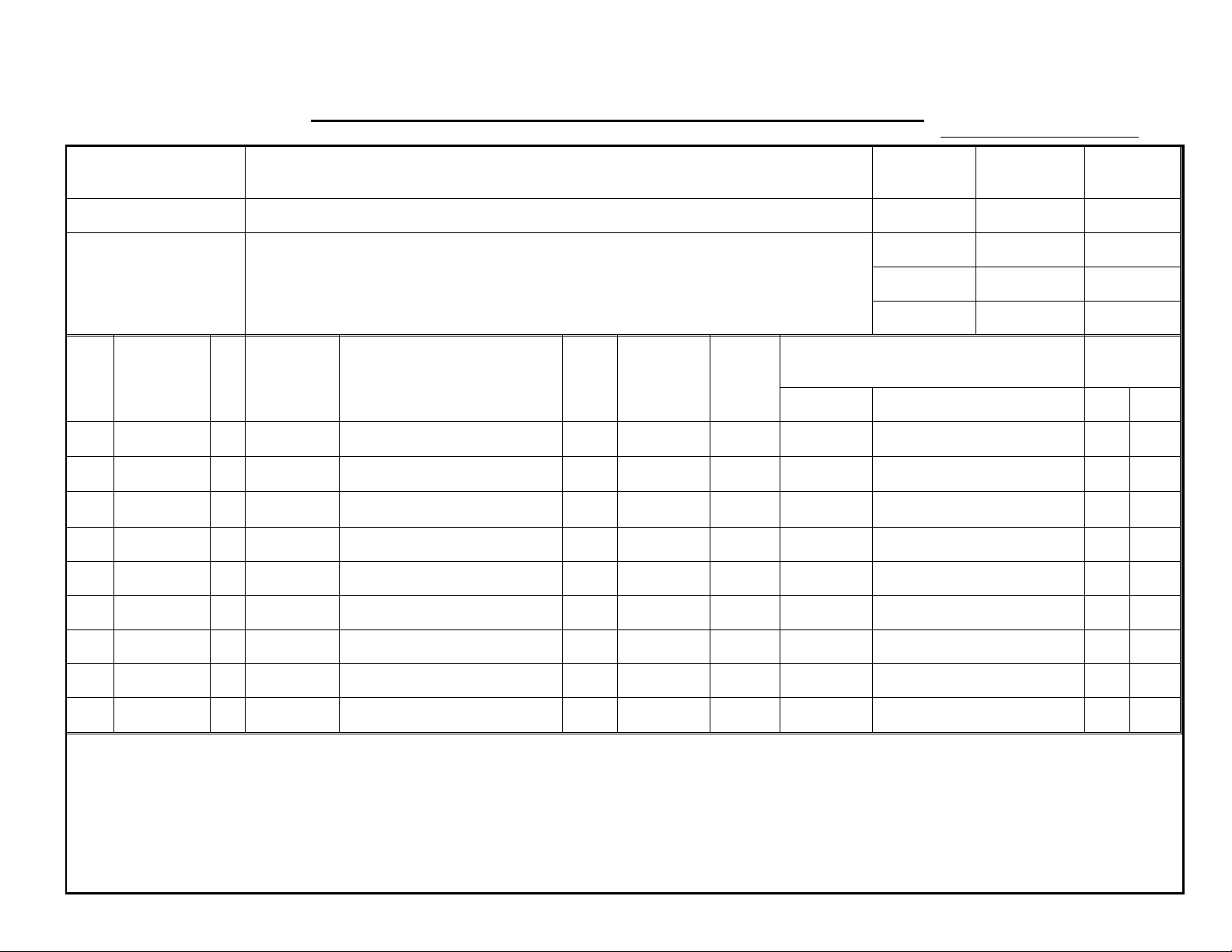
MODIFICATION BULLETIN NO. 1 PAGE 1 OF 5
ISSUED ON: October 15, ’93
Model N865 (VT2105, Ges5325, Rex1250, NSA CP325) Volt/Hz
Modified Article Reverse Roller Clutch
Reason for
To erase horizontal white line in photo mode
Modification
Draw
No.
Old Parts
No.
C2168122 C2168123 Main Control Board - 230V
C2168112 C2168113 Main Control Board - 115V
C2158045 C2158057 IC - Main Board
New Parts
No.
Description Rank
Q’ty Used
Old → New
1 → 1
1 → 1
1 → 1
Date of
Modification
Inter-
change-
ability
O/O 31 67
O/O 31 67
O/O 32 67
Part needed for replacement by new part
Part No. Description No. Page
Serial
Number
Parts
Catalog
Rank: A : Replace with new parts immediately.B : Replace with new parts at time of repair.C : Replace with new parts at time of overhaul.
I Interchangeability:
(1) When old and new parts are not mutually interchangeable, use additional parts or an assembly part as indicated in "Parts needed for
replacement by new part" to install the new part.
(2) The mark to the left of the slash indicates whether the old part can be used in the new machine, and the mark to the right indicates whether
the new part can be used in the old machine. x = Not interchangeable o = Interchangeable
Page 2
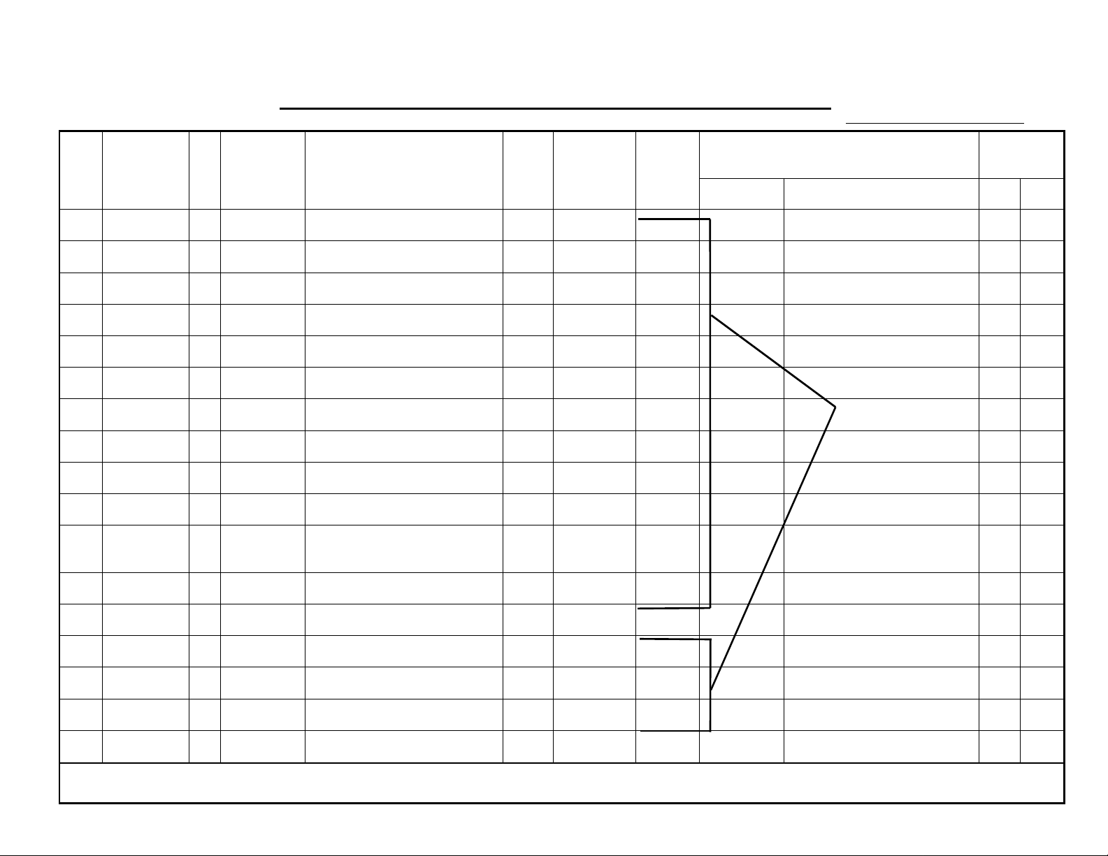
MODIFICATION BULLETIN NO. 1 PAGE 2 OF 5
ISSUED ON: October 15, ’93
Draw
No.
Old Parts
No.
C2008440 Reverse Roller Solenoid
C2004223 Reverse Solenoid Bracket
C2004216 Reverse Roller Clutch Barrel
C2004217 Reverse Roller Clutch Sleeve
C2004215 Reverse Roller Clutch Spring
C2004213 Pulley - 28T
C2014068 Reverse Roller Clutch Pawl
56073616 Guide Plate Spring
06220060E Spring Pin - 2 x 6mm
03140080Z Philips Screw - 4 x 8
05740060E
New Parts
No.
Description Rank
Hexagon Headless Screw M4 x 6
Q’ty Used
Old → New
1 → 0
1 → 0
1 → 0
1 → 0
1 → 0
1 → 0
1 → 0
1 → 0
1 → 0
1 → 0
1 → 0
Inter-
change-
ability
Part needed for replacement by new part
Part No. Description No. Page
X/O as a set
Parts
Catalog
03130200Z Philips Screw - 3 x 5
C2134046 Upper Reverse Roller
C2154200 Clutch Stopper
C2158240 Reverse Roller Clutch
09604008Z Flange Head Screw - 4 x 8
C2154046 Upper Reverse Roller
1 → 0
1 → 0
0 → 1
0 → 1
0 → 1
0 → 1
Page 3

MODIFICATION BULLETIN NO. 1 PAGE 3 OF 5
ISSUED ON: October 15, ’93
DETAILS OF MODIFICATION
It has been found that a horizontal thin white line appears 64 mm from the lead ing edge of prints. The line may be visible whe n
the image is made using the photo mode . This line is caused by a shock wave when the master is clamped by the drum master
clamper.
1. To erase this white line, th e software has been changed to de lay th e timing of the master clampin g. Wit h th e old software,
the reverse roller solenoid [A] and the ma ste r clamper solenoid were turned of f at the same time . (Due to th e slow resp on se of
the old spring clutch, th e reve rse rolle r st ops f eeding the master after the maste r was cla mpe d. ) Th e new so ft ware ena ble s tha t
the master is clamped when the master is fed 2 mm further after the reverse roller stops feeding the master. This allows t o
make a small buckle of the master, which ab sorb s the shock wave , be twe en the plat en roller an d th e reverse roller before the
leading edge of the mast er is clamped.
The new ROM can be used also for existing machines. The only side ef fe ct is t hat the image on prints is forwarded about 1 or 2
mm due to the slow response of the old mechan ism. (This valu e varies due to ratchets of the clutch gea r.) If the old ROM is
used for a modified ma chin e (this is the same situation as the ne w clu tch me cha nism installed on the old machine), the image
is shifted approximately 0.6 mm backwards.
NOTE: The part numbers of the RO Ms and main PCBs for the VT2000 series have been changed. The main PCB s have not
been changed except for the ROMs. The old PCBs and the ne w PCBs are in te rchangeable.
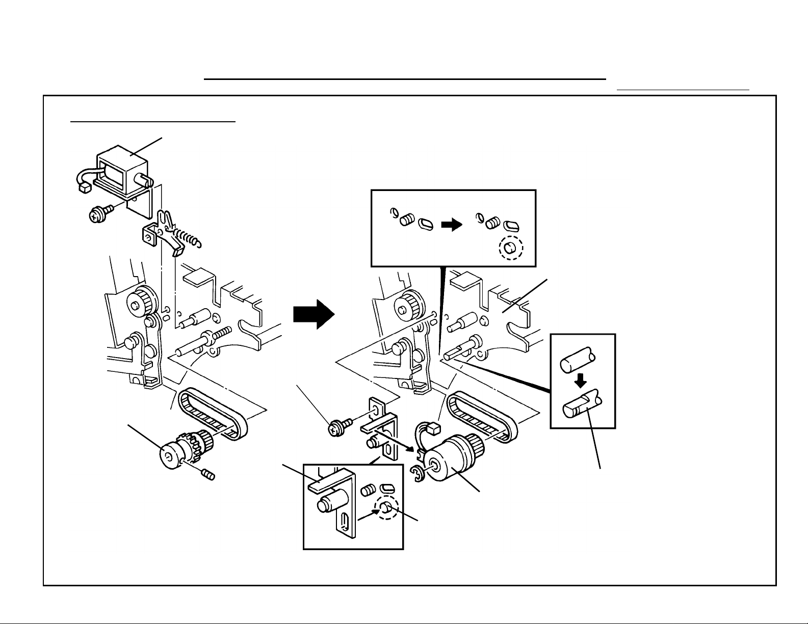
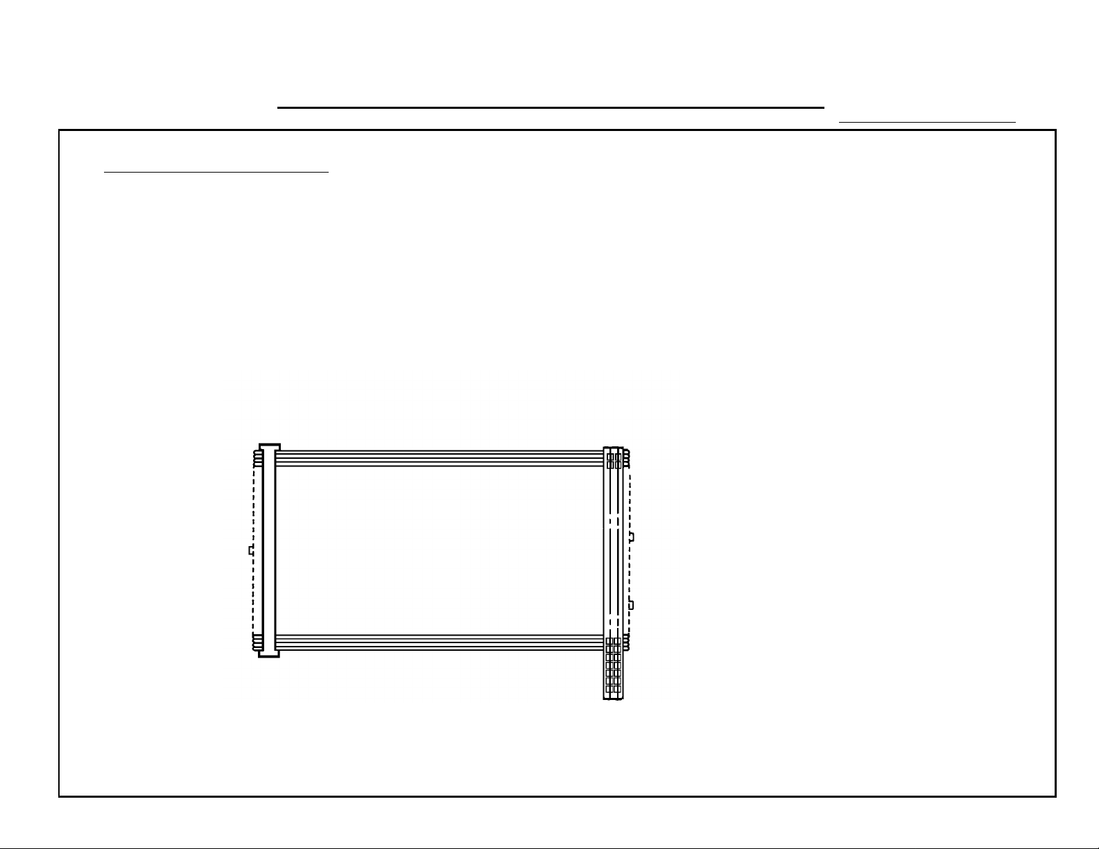
2. To enable the proper reverse rolle r stop timing , the reverse roller clutch mechanism ha s been cha ng ed from th e con bination
of a solenoid [A] and a spring clutch [B] to an elect rical clutch [C]. To cope with the strictly contro lled reverse roller stop timing,
the electrical clutch respo nds a lit tle bit quicker than the old clutch mechanism. (If the old sprin g clutch is used, the only side
effect is as mentioned above.)
To make assembly of the clutch sto pp er [E ] in the factory easier, a pro ject ion [F] is added on the right side plate [D]
(C2164005). Even if the side plate does not have this projection, the clutch stopp er can be installed on the side plate with one
screw [G] (09604008Z). So, the part number of the righ t side plat e ha s not been changed. Also, th e shape of th e up pe r re verse
roller shaft [H] has been changed to match the elect rical clut ch. The old spring clutch [B] can be replaced with the new electrical
clutch [C] (C2158240) with the clutch stopper [G ] (C21 54 200) an d the upper reverse roller (C2154046).
Page 4
T. Ito, Manager
Copier Technical Support
MODIFICATION BULLETIN NO. 1 PAGE 4 OF 5
[C]
DETAILS OF MODIFICATION
[B]
ISSUED ON: October 15, ’93
[D]
[A]
[G]
[E]
[H]
[F]
Page 5

MODIFICATION BULLETIN NO. 1 PAGE 5 OF 5
ISSUED ON: October 15, ’93
MODEL NAME
Ges5325 Rex1250
NSA CP325
Ricoh VT2105 120/60 USA, Canada C216-17 C3213040001
Ges5325 Rex1250
NSA CP325
Ricoh VT2105 230/50 Europe C216-27 C3213040031
Ricoh VT2105 230/60 Asia C216-29 C3213040106
V/Hz DESTINATION CODE SERIAL NUMBER
120/60 USA, Canada C216-12 50823040001
230/50 Europe, Asia C216-22 50813040001
Page 6
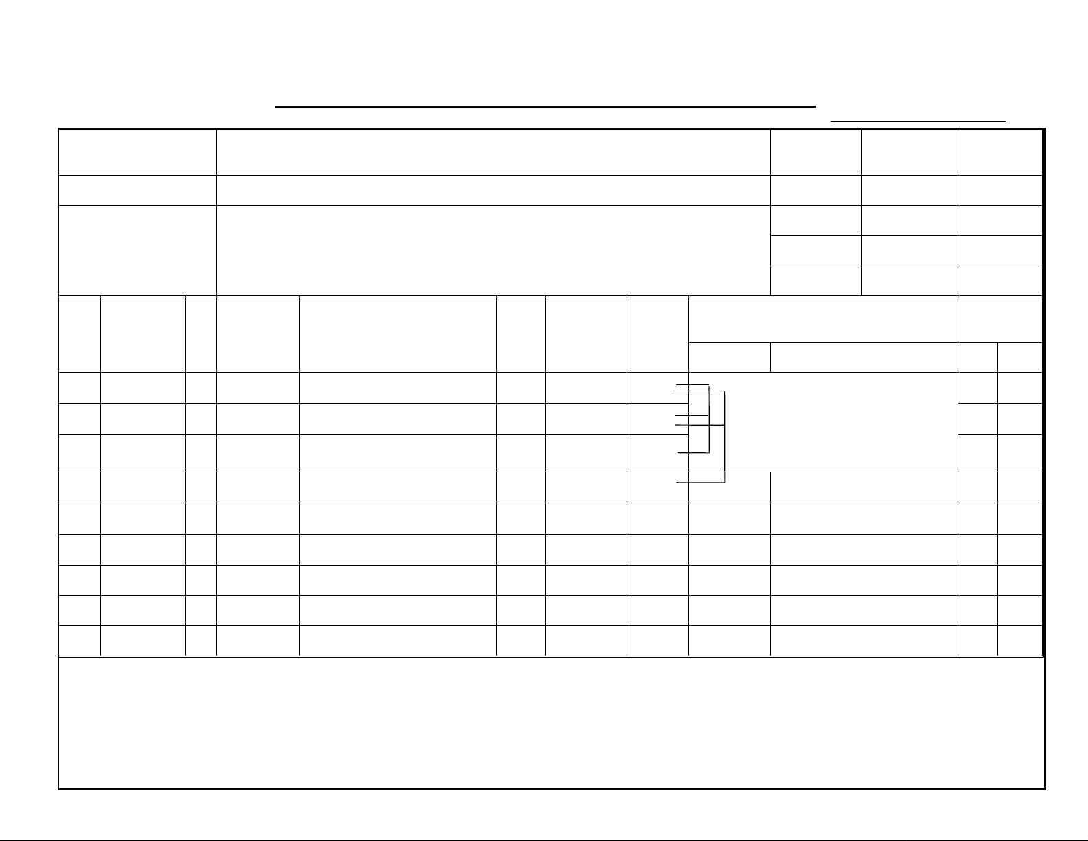
MODIFICATION BULLETIN NO. 2 PAGE 1 OF 3
ISSUED ON: October 15, ’93
Model N865 (VT2105, Ges5325, Rex1250, NSA CP325) Volt/Hz
Modified Article Main Board, Image Processing Board
Reason for
Gestetner version: To enable computer link up
Modification
Draw
No.
Old Parts
No.
C2158088 C2078088 Flat Cable - Main Board
C2158002 C2168002 Image Processing Board
C2168123 C2168062 Main Control Board - 230V
C2168113 C2168052 Main Control Board - 115V
C2158057 C2168057 IC - Main Board
New Parts
No.
Description Rank
Q’ty Used
Old → New
1 → 1
1 → 1
1 → 1
1 → 1
1 → 1
Date of
Modification
Inter-
change-
ability
X/X
X/X 25 67
X/X 31 67
X/X 31 67
X/X 32 67
Part needed for replacement by new part
Part No. Description No.Page
O/O as a set
(X/O, if the computer
link up is necessary.)
Serial
Number
Parts
Catalog
19 67
C2169501 Flat Cable - Main Board
Rank: A : Replace with new parts immediately.B : Replace with new parts at time of repair.C : Replace with new parts at time of overhaul.
I Interchangeability:
(1) When old and new parts are not mutually interchangeable, use additional parts or an assembly part as indicated in "Parts needed for
replacement by new part" to install the new part.
(2) The mark to the left of the slash indicates whether the old part can be used in the new machine, and the mark to the right indicates whether
the new part can be used in the old machine. x = Not interchangeable o = Interchangeable
0 → 1
**
Page 7
MODIFICATION BULLETIN NO. 2 PAGE 2 OF 3
Connected with
the new board
ISSUED ON: October 15, ’93
DETAILS OF MODIFICATION
To enable computer link up, the main cont rol bo ard and the image proce ssing boa rd have be en change d,
including the ROM on the main board (IC - main board). Due to this modification, the numbe r of connector
pins between the main cont rol bo ard and the image processing boa rd ha s bee n incre ase d. This is the
reason why the interchangeability of each board is X/X.
To enable to connect the new bo ard and the old board, the flat cable - main board (C2169501) has been
registered as a service part. A new board can be installe d on the old mach ine with this cable. Also, an old
board can be installed on th e ne w machine with this cable. To enable comp ut er link up , the new main
control board, image processing board, and flat cable must be used as a set.
Connected with
the old board
C2169501
T. Ito, Manager
Copier Technical Support
Page 8

MODIFICATION BULLETIN NO. 2 PAGE 3 OF 3
ISSUED ON: October 15, ’93
MODEL NAME
Ges5325 Rex1250
NSA CP325
Ricoh VT2105 120/60 USA, Canada C216-17
Ges5325 Rex1250
NSA CP325
Ricoh VT2105 230/50 Europe C216-27 C3213080001
Ricoh VT2105 230/60 Asia C216-29 C3213080036
V/Hz DESTINATION CODE SERIAL NUMBER
120/60 USA, Canada C216-12 50823080001
From September ’93
Production
230/50 Europe, Asia C216-22 50813080001
Page 9
MODIFICATION BULLETIN NO. 3 PAGE 1 OF 3
ISSUED ON: October 15, ’93
Model N865 (VT2105, Ges5325, Rex1250, NSA CP325) Volt/Hz
Modified Article Main Board, Image Processing Board
Reason for
Parts Standardization
Modification
Draw
No.
Old Parts
No.
C2158088 C2078088 Flat Cable - Main Board
C2158002 C2168002 Image Processing Board
C2168123 C2168062 Main Control Board - 230V
C2168113 C2168052 Main Control Board - 115V
C2158057 C2168057 IC - Main Board
New Parts
No.
Description Rank
Q’ty Used
Old → New
1 → 1
1 → 1
1 → 1
1 → 1
1 → 1
Date of
Modification
Inter-
change-
ability
X/X O/O as a set 19 67
X/X 25 67
X/X 31 67
X/X 31 67
X/X 32 67
Part needed for replacement by new part
Part No. Description No. Page
Serial
Number
Parts
Catalog
Rank: A : Replace with new parts immediately.B : Replace with new parts at time of repair.C : Replace with new parts at time of overhaul.
I Interchangeability:
(1) When old and new parts are not mutually interchangeable, use additional parts or an assembly part as indicated in "Parts needed for
replacement by new part" to install the new part.
(2) The mark to the left of the slash indicates whether the old part can be used in the new machine, and the mark to the right indicates whether
the new part can be used in the old machine. x = Not interchangeable o = Interchangeable
C2169501 Flat Cable Main PCB
0 → 1
**
Page 10

MODIFICATION BULLETIN NO. 3 PAGE 2 OF 3
Connected with
the new board
ISSUED ON: October 15, ’93
DETAILS OF MODIFICATION
Due to parts standardization, the main contro l b oa rd and the image processing board have been
changed, including the ROM on th e main board (IC - main board). Due to this modifica tio n, the number
of connector pins betwe en the main con trol board and the Image proce ssing boa rd ha s bee n
increased. This is the reason why the interchangea bilit y of ea ch bo ard is X/ X.
To enable to connect th e ne w boa rd an d th e old board, the flat cable - main boa rd (C21 69 50 1) ha s
been registered as a service part. A new board can be inst alle d on the old mach ine with this cable.
Also, an old board can be installed on the new machine with th is cable.
Connected with
the old board
C2169501
T. Ito, Manager
Copier Technical Support
Page 11

MODIFICATION BULLETIN NO. 3 PAGE 3 OF 3
ISSUED ON: October 15, ’93
MODEL NAME
Ges5325 Rex1250
NSA CP325
Ricoh VT2105 120/60 USA, Canada C216-17
Ges5325 Rex1250
NSA CP325
Ricoh VT2105 230/50 Europe C216-27 C3213080001
Ricoh VT2105 230/60 Asia C216-29 C3213080036
V/Hz DESTINATION CODE SERIAL NUMBER
120/60 USA, Canada C216-12 50823080001
From September ’93
Production
230/50 Europe, Asia C216-22 50813080001
Page 12
MODIFICATION BULLETIN NO. 4 PAGE 1 OF 2
ISSUED ON: October 31, ’93
Model N865 (VT2105, Ges5325, Rex1250, NSA CP325) Volt/Hz
Modified Article Parts Catalog
Reason for
Parts catalog correction
Modification
Please correct your parts catalog as follows:
Parts Catalog
Incorrect P/N Correct P/N Description Q’ty Used
Index No. Page
C2018453 12040801 Push Switch 1 20 67
Date of
Modification
Serial Number
S. Hamano, Assistant General Manager
Technical Support Department
Page 13
MODIFICATION BULLETIN NO. 4 PAGE 2 OF 2
ISSUED ON: October 31, ’93
MODEL NAME
Ges5325 Rex1250
NSA CP325
Ricoh VT2105 120/60 USA, Canada C216-17
Ges5325 Rex1250
NSA CP325
Ricoh VT2105 230/50 Europe C216-27
Ricoh VT2105 230/60 Asia C216-29
V/Hz DESTINATION CODE SERIAL NUMBER
120/60 USA, Canada C216-12
230/50 Europe, Asia C216-22
Page 14

MODIFICATION BULLETIN NO. 5 PAGE 1 OF 2
ISSUED ON: February 15, ’94
Model N865 (VT2105, Ges5325, Rex1250, NSA CP325) Volt/Hz
Modified Article ADF Stopper
Reason for
Parts standardization
Modification
Due to parts standardization, the following part has been changed.
Old P/N New P/N Description Q’ty Used
C2023131 C2093141 Stopper
1 → 1
change-
Date of
Modification
Inter-
ability
O/O 31 49
Parts Catalog
Index No. Page
Serial Number
S. Hamano, Assistant General Manager
Technical Support Department
Page 15

MODIFICATION BULLETIN NO. 5 PAGE 2 OF 2
ISSUED ON: February 15, ’94
MODEL NAME
Ges5325 Rex1250
NSA CP325
Ricoh VT2105 120/60 USA, Canada C216-17
Ges5325 Rex1250
NSA CP325
Ricoh VT2105 230/50 Europe C216-27
Ricoh VT2105 230/60 Asia C216-29
A.B. Dick 6520 120/60 USA, Canada C216-18
V/Hz DESTINATION CODE SERIAL NUMBER
120/60 USA, Canada C216-12
230/50 Europe, Asia C216-22
Page 16

MODIFICATION BULLETIN NO. 6 PAGE 1 OF 2
ISSUED ON: February 15, ’94
Model N865 (VT2105, Ges5325, Rex1250, NSA CP325) Volt/Hz
Modified Article Parts Catalog
Reason for
Parts catalog correction
Modification
Please correct your parts catalog as follows:
Incorrect P/N Correct P/N Description Index Page
C2136044 C2136050 Exit Pawl 14 31
Date of
Modification
Serial Number
S. Hamano, Assistant General Manager
Technical Support Department
Page 17

MODIFICATION BULLETIN NO. 6 PAGE 2 OF 2
ISSUED ON: February 15, ’94
MODEL NAME
Ges5325 Rex1250
NSA CP325
Ricoh VT2105 120/60 USA, Canada C216-17
Ges5325 Rex1250
NSA CP325
Ricoh VT2105 230/50 Europe C216-27
Ricoh VT2105 230/60 Asia C216-29
A.B. Dick 6520 120/60 USA, Canada C216-18
V/Hz DESTINATION CODE SERIAL NUMBER
120/60 USA, Canada C216-12
230/50 Europe, Asia C216-22
Page 18

MODIFICATION BULLETIN NO. 7 PAGE 1 OF 2
ISSUED ON:February 15, ’94
Model N865 (VT2105, Ges5325, Rex1250, NSA CP325) Volt/Hz
Modified Article Upper Hinge - Front Door
Reason for
Parts standa rdization
Modification
Due to parts standardization, the followin g part has bee n changed.
Old P/N New P/N Description Q’ty Used
C2132405 C2162405 Upper Hinge - Front Door
1 → 1
Date of
Modification
Inter-
change-
ability
O/O 25 9
Parts Catalog
Index No. Page
Serial Number
S. Hama no, Assist ant General Manager
Tec hnic al Support Department
Page 19

MODIFICATION BULLETIN NO. 7 PAGE 2 OF 2
ISSUED ON:February 15, ’94
MODEL NAME
Ges5325 Rex1250
NSA CP325
Ricoh VT2105 120/60 USA, Canada C216-17
Ges5325 Rex1250
NSA CP325
Ricoh VT2105 230/50 Europe C216-27
Ricoh VT2105 230/60 Asia C216-29
A.B. Dick 6520 120/60 USA, Canada C216-18
V/Hz DESTINATION CODE SERIAL NUMBER
120/60 USA, Canada C216-12
230/50 Europe, Asia C216-22
Page 20

MODIFICATION BULLETIN NO. 8 PAGE 1 OF 5
ISSUED ON: July 15, ’94
Model N865, N860 Volt/Hz
Modified Article Parts Catalog for N860 (VT2005, Ges5323, Rex1245, NST CP323)
Reason for
Parts catalog for N860
Modification
Date of
Modification
Serial Number
The mass-production of the N860 (C215 ) started from January ’94. To konw the diffe ren ce be twe en the N865 and N860 ,
Please refer to RTB No. 10 of the VT2000 series.
Please add the followingunique parts to the N860 in the N865 parts catalog, so that N865 parts catalog covers all the
parts for the N860.
Part Number Description Q’ty Used
Index No. Page
C2152771 Decal - Drum Replacement (C215) (Ricoh) 1 13 9
C2112871 Decal - Drum Replacement (C215) (NRG) 1 13 9
C2152712 Front Cover (C215) (Ricoh) 1 18 9
C2152812 Front Cover (C215) (NRG) 1 18 9
Parts Catalog
C2152815 Model Plate - GES 1 *30 9
C2152816 Model Plate - REX 1 *30 9
C2152817 Model Plate - NST 1 *30 9
C2053140 Original Table - A4 (C215) (Ricoh) 1 2 53
C2113138 Original Table - A4 (C215) (NRG) 1 2 53
C2158052 Main Control Board - 230V (C215) 1 31 67
C2158608 Operating Instructions - English (C215) (Ricoh) 1 24 95
C2158698 Operating Instructions - English (C215) (NRG) 1 24 95
*New Index
Page 21

MODIFICATION BULLETIN NO. 8 PAGE 2 OF 5
DETAILS OF MODIFICATION
Please add the following pages (48-2 and 49-2) for the scanner section 1 of the N860 (C2 15 )
ISSUED ON: July 15, ’94
Page 48-2
Page 22

DETAILS OF MODIFICATION
Page 49-2
MODIFICATION BULLETIN NO. 8 PAGE 3 OF 5
ISSUED ON: July 15, ’94
Part Number Description Q’ty Used
C200 3049 Pressure Arm Spring 4 1
C200 3052 Adjusting Shaft 2 2
C201 2454 Decal - Original Table Cover 1 3
C201 3024 Original Table Cover (Ricoh) 1 4
C2113211 Original Table Cover (NRG) 1 4
C200 3048 Pressure Arm 4 5
C200 3047 Shaft - Scanner Unit 1 6
C200 3053 Magnet Catch 2 7
C200 3045 Shoulder Screw - Inner Cover 2 8
C200 3041 Inner Cover - Original Transport 1 9
C200 3065 Original Press Roller 1 10
C202 3107 Transport Roller 1 11
C201 3066 Original Guide 1 12
C201 3067 Platen Plate 1 13
Parts Catalog
Index No.
0720 0050Z Retaining Ring - M5 100
0720 0030Z Retaining Ring - M3 101
0313 0050Z Philips Screw - 3 x 5 102
0313 0140Z Philips Pan Head Screw - M3 x 14 103
0313 0120Z Philips Screw - 3 x 12 104
Page 23

DETAILS OF MODIFICATION
MODIFICATION BULLETIN NO. 8 PAGE 4 OF 5
ISSUED ON: July 15, ’94
Part Number Description Q’ty Used
0433 0080Z Tapping Screw - M3 x 8 105
0707 6150B Bushing - 6 x 15mm 106
0720 0040Z Retaining Ring - M4 107
0803 0043 Screw - M3 x 11 108
0701 0030Z Flat Washer - M3 109
Parts Catalog
Index No.
S. Hamano, Assistant General Manager
Technical Support Department
Page 24

MODIFICATION BULLETIN NO. 8 PAGE 5 OF 5
ISSUED ON: July 15, ’94
MODEL NAME
Ges5325 Rex1250
NSA CP325
Ricoh VT2105 120/60 USA, Canada C216-17
Ges5325 Rex1250
NSA CP325
Ricoh VT2105 230/50 Europe C216-27
Ricoh VT2105 230/60 Asia C216-29
A.B. Dick 6520 120/60 USA, Canada C216-18
Ges5323 Rex1245
NSA CP323
Ricoh VT2005 110/60 Taiwan C215-19
Ges5323 Rex1245
NSA CP323
V/Hz DESTINATION CODE SERIAL NUMBER
120/60 USA, Canada C216-12
230/50 Europe, Asia C216-22
110/60 Taiwan C215-13
230/60 Asia C215-23
Ricoh VT2005 230/60 Asia C215-29
Page 25

Reissued on: February 15, ’95
ISSUED ON: September 15, ’94
MODIFICATION BULLETIN NO. 9 PAGE 1 OF 2
Model N865, N860 Volt/Hz
Modified Article Circuit Breaker
Reason for
Vender change
Modification
Due to a vender change, the following parts have been changed.
Inter-
Old P/N New P/N Description Q’ty Used
C2032059 C2162059 Circuit Breaker Bracket
11070134 11070761 Circuit Breaker - 3A (220/240V)
11070154 11070782 Circuit Breaker - 5A (120V)
11070154 11070783 Circuit Breaker - 7A (110V-TWN)
1 → 1
1 → 1
1 → 1
1 → 1
change-
ability
X/X 38 67
X/X 126 67
X/X 126 67
X/X 126 67
Date of
Modification
Parts Catalog
Index No. Page
O/O as a set
Serial Number
S. Hamano, Assistant General Manager
Technical Support Department
Page 26

MODIFICATION BULLETIN NO. 9 PAGE 2 OF 2
Reissued on: February 15, ’95
ISSUED ON: September 15, ’94
MODEL NAME
Ges5325 Rex1250
NSA CP325
Ricoh VT2105 120/60 USA, Canada C216-17 C3214020001
Ges5325 Rex1250
NSA CP325
Ricoh VT2105 230/50 Europe C216-27 C3214020031
Ricoh VT2105 230/60 Asia C216-29 C3214020106
A.B. Dick 6520 120/60 USA, Canada C216-18 From March ’94 Production
Ges5323 Rex1245
NSA CP323
Ricoh VT2005 110/60 Taiwan C215-19 From March ’94 Production
Ges5323 Rex1245
NSA CP323
V/Hz DESTINATION CODE SERIAL NUMBER
120/60 USA, Canada C216-12 50824020001
230/50 Europe, Asia C216-22 50814020001
110/60 Taiwan C215-13 From March ’94 Production
230/60 Asia C215-23 55114020001
Ricoh VT2005 230/60 Asia C215-29 From March ’94 Production
Page 27

MODIFICATION BULLETIN NO. 10 PAGE 1 OF 2
ISSUED ON: September 15, ’94
Model N865, N860 Volt/Hz
Modified Article AC Drive Board
Reason for
To improve reliability
Modification
Inter-
Old P/N New P/N Description Q’ty Used
12081245 Relay - DC24V
12081042 Power Relay - DC24V
4 → 2
0 → 2
change-
ability
X/O * 130 87
Parts Catalog
Index No. Page
109 87
Date of
Modification
* New Index
To improve reliability, the relays (RA303 and RA304) for the driving paper ta ble drive mot or ha ve be en chan ged.
Serial Number
S. Hamano, Assistant General Manager
Technical Support Department
Page 28

MODIFICATION BULLETIN NO. 10 PAGE 2 OF 2
ISSUED ON: September 15, ’94
MODEL NAME
Ges5325 Rex1250
NSA CP325
Ricoh VT2105 120/60 USA, Canada C216-17 From August ’94 Production
Ges5325 Rex1250
NSA CP325
Ricoh VT2105 230/50 Europe C216-27 C3213070001
Ricoh VT2105 230/60 Asia C216-29 C3213070071
A.B. Dick 6520 120/60 USA, Canada C216-18 From 1st Production
Ges5323 Rex1245
NSA CP323
Ricoh VT2005 110/60 Taiwan C215-19 From 1st Production
Ges5323 Rex1245
NSA CP323
V/Hz DESTINATION CODE SERIAL NUMBER
120/60 USA, Canada C216-12 From August ’94 Production
230/50 Europe, Asia C216-22 50813070001
110/60 Taiwan C215-13 From 1st Production
230/60 Asia C215-23 From 1st Production
Ricoh VT2005 230/60 Asia C215-29 From 1st Production
Page 29

MODIFICATION BULLETIN NO. 11 PAGE 1 OF 2
ISSUED ON: September 15, ’94
Model N865, N860 Volt/Hz
Modified Article Transformer
Reason for
To meet new safety standard
Modification
Inter-
Old P/N New P/N Description Q’ty Used
C2018155 C2168155 Transformer - 235V/105V
C2032018 C2162018 Transformer Bracket
1 → 1
1 → 1
change-
ability
X/X 35 67
X/X 36 67
Index No. Page
Modification
Parts Catalog
X/O as a set
To meet new safety stan da rd, the transformer for the 220/240 V mach ines has been changed. Due to th is
modification, th e transformer bracket has also be en chan ge d.
Date of
Serial Number
S. Hamano, Assistant General Manager
Technical Support Department
Page 30

MODIFICATION BULLETIN NO. 11 PAGE 2 OF 2
ISSUED ON: September 15, ’94
MODEL NAME
Ges5325 Rex1250
NSA CP325
Ricoh VT2105 120/60 USA, Canada C216-17 From August ’93 Production
Ges5325 Rex1250
NSA CP325
Ricoh VT2105 230/50 Europe C216-27 C3213070001
Ricoh VT2105 230/60 Asia C216-29 C3213070071
A.B. Dick 6520 120/60 USA, Canada C216-18 From August ’93 Production
Ges5323 Rex1245
NSA CP323
Ricoh VT2005 110/60 Taiwan C215-19 From August ’93 Production
Ges5323 Rex1245
NSA CP323
V/Hz DESTINATION CODE SERIAL NUMBER
120/60 USA, Canada C216-12 From August ’93 Production
230/50 Europe, Asia C216-22 50813070001
110/60 Taiwan C215-13 From August ’93 Production
230/60 Asia C215-23 From August ’93 Production
Ricoh VT2005 230/60 Asia C215-29 From August ’93 Production
Page 31

MODIFICATION BULLETIN NO. 12 PAGE 1 OF 6
ISSUED ON: February 15, ’96
Model N865, N860 Volt/Hz
Modified Article
Reason for
Modification
Parts Catalog
Parts Catalog Correction
Correct your parts catalog as follows:
Page 9 EXTERIOR section
1. NRG version only
Correct the part number as follows:
Index No. Incorrect PN Correct P/N Description
2 C2032761 C2122841 Master Eject Box Door - NRG
2. Ricoh version only
Correct the description as follows:
Date of
Modification
Serial Number
Index No. Incorrect PN Incorrect Description Correct Description
18 C2162702 Front Cover - LT Front Cover
* This part is used not only for the U. S. A. version machines, but also for all Ricoh version machines.
22 C2162705 Front Door A’ssy Front Door Ass’y - LT
3. Ricoh version only
Correct the index number and descrip tio n as follow:
Incorrect Index Correct Index P/N Incorrect Description Correct Description
18 22 C2162712 Front Cover - A4 Front Door Ass’y - A4
Page 32

MODIFICATION BULLETIN NO. 12 PAGE 2 OF 6
4. NRG version only
Add the following parts:
Index No. P/N Description Q’ty
22 C2162812 Front Door Cover - A4 (NRG Generic) 1
22 C2162805 Front Door Cover - LT (NRG Generic) 1
5. All versions
Correct the illustration in th e EXTERIOR section as follows:
ISSUED ON: February 15, ’96
* Index 7
Operation Panel (Se e ind ex 4,
Page 67 of your parts catalog)
Page 33

MODIFICATION BULLETIN NO. 12 PAGE 3 OF 6
Page 41 DRUM SECTION
1. A. B. Dick version only
Correct the part number as follows:
Index No. Incorrect P/N Correct P/N Description
25 C2004826 C2164826 Pump Rubber
Page 49 SCANNER SECTION 1
1. Ricoh and A. B. Dick versions only
Correct the part number as follows:
Index No. Incorrect P/N Correct P/N Description
ISSUED ON: February 15, ’96
* C2163105 C2163120 ADF Unit - LT
Page 34

MODIFICATION BULLETIN NO. 12 PAGE 4 OF 6
Index 13
* New Index 29
Index 24
Page 59 PLOTTER / MASTER FEED SECTION 2
1. All versions
Add the following part and correct the illustration as shown belo w:
New Index No. P/N Description Q’ty
29 C2008415 Motor / Cable Ass’y 1
* The motor (C2008418) and flat cable (C2008417) are soldered, and they are supp lied also as an
assembled part as shown below.
ISSUED ON: February 15, ’96
Index 22
Page 35

MODIFICATION BULLETIN NO. 12 PAGE 5 OF 6
* Index 118
(Incorrect)
* 119
Page 61 PLOTTER / MASTER FEED SECTION 3
1. All versions
Add the following parts and correct the illustration as shown below:
New Index P/N Description Q’ty
ISSUED ON: February 15, ’96
56
57
58
59
119
120
C2002338
53241658
H0022226
H0121181
07200020Z
07200025Z
Gear - 20T
Bushing - 4 x 8 x 4.5 mm
Bushing - Head Roller
Bushing - M6
Retaining Ring - M2
Retaining Ring - M2.5
Incorrect (* : Incorrect inde x numbe r or il lus tra tion)
* Index 118 (Incorrect)
Index 42
* Index 5 (Incorrect)
* Index 113
(Incorrect)
Index 4
Correct (* : New index number or corre cte d ill ustr ati on)
* 107
Index 42
* 59
1
1
1
2
1
1
* Index 100
(Incorrect)
Index 38
* 59
* 5
* 56
* 120
Index 4
* 107
* 57
Index 38
* 58
M. Iwasa, Manager
Technical Support Departme nt
Page 36

MODIFICATION BULLETIN NO. 12 PAGE 6 OF 6
ISSUED ON: February 15 ’96
MODEL NAME
Ges5325 Rex1250
NSA CP325
Ricoh VT2105 120/60 USA, Canada C216-17
Ges5325 Rex1250
NSA CP325
Ricoh VT2105 230/50 Europe C216-27
Ricoh VT2105 230/60 Asia C216-29
A.B. Dick 6520 120/60 USA, Canada C216-18
Ges5323 Rex1245
NSA CP323
Ricoh VT2005 110/60 Taiwan C215-19
Ges5323 Rex1245
NSA CP323
Ricoh VT2005 230/60 Asia C215-29
V/Hz DESTINATION CODE SERIAL NUMBER
120/60 USA, Canada C216-12
230/50 Europe, Asia C216-22
110/60 Taiwan C215-13
230/60 Asia C215-23
Page 37

MODIFICATION BULLETIN NO. 13 PAGE 1 OF 5
ISSUED ON: February 15, ’96
Model N865, N860 Volt/Hz
Modified Article
Reason for
Modification
Draw
No.
Old Parts
C2002005 C2222072 Bottom Stay
C2032015 Bracket
C2154505 C2194505
C2154506 C2194506 Stopper Base
C2034512 C2244512 Grounding Spring Plate
No.
Due to parts standardization with other models
New Parts
No.
C2242015
Description Rank
Image Processing Board
Bracket
Drum Stopper Ass’y
Q’ty Used
Old→New
2 → 2
1 → 0
0 → 1
1 → 1
1 → 1
1 → 1
Date of
Modification
Inter-
change-
ability
O/O 11 11
O/O 13 11
O/O 27 11
O/O 39 11
O/O 46 11
Parts needed for replacement by new part
Part No. Description No. Page
Serial
Number
Parts
Catalog
C2002340 Washer
07010030Z
C2012226 C2192226 Gear - 22T
Rank: A : Replace with new parts immediately. B : Replace with new parts at time of repair. C : Replace with new parts at time of overhaul.
Interchangeability:
(1) When old and new parts are not mutually interchangeable, use additional parts or an assembly part as indicated in "Parts needed for
replacement by new part" to install the new part.
(2) The mark to the left of the slash indicates whether the old part can be used in the new machine, and the mark to the right indicates whether
the new part can be used in the old machine. x = Not interchangeable o = Interchangeable
Flat Washer - M3
1 → 0
0 → 1
1 → 1
O/O 24 13
O/O 33 13
Page 38

MODIFICATION BULLETIN NO. 13 PAGE 2 OF 5
ISSUED ON: February 15, ’96
Draw
No.
Old Parts
No.
14030539
55061535 Right Side Pad
New Parts
No.
AW020041 Photointerruptor
C2095092
Description Rank
Photointerruptor EE-SX450-P1
Rubber Plate Lever
Q’ty Used
Old → New
n → n
2 → 0
0 → 2
Inter-
change-
ability
O/O
O/O 6 17
Part needed for replacement by new part
Part No. Description No. Page
Parts
Catalog
118
1111517
115
1112127
111
1173149
105
1065167
C2035126 C2245126 Right Rack - Paper Feed
C2035128 C2245128 Left Rack - Paper Feed
1 → 1
1 → 1
O/O 25 17
O/O 40 17
Page 39

MODIFICATION BULLETIN NO. 13 PAGE 3 OF 5
ISSUED ON: February 15, ’96
Draw
No.
Old Parts
No.
C2005207 C2195127 Sectorgear Stud
C2035175 C2245101 Sector Gear
55015929
56001086
08077018 Washer - M10
07200080Z Retaining Ring - M8
C2136034 Gear
New Parts
No.
C2196033
Description Rank
Spacer - 5.2 mm x 16 mm x
1
Spacer - 10.2 x 20
Gear - 50Z
Q’ty Used
Old → New
1 → 1
1 → 1
1 → 0
1 → 0
1 → 0
n → n-1
1 → 0
0 → 1
Inter-
change-
ability
X/X O/O as a set 3 25
X/X 5 25
O/O 9 33
Part needed for replacement by new part
Part No. Description No. Page
Parts
Catalog
125
625
104 25
106 25
C2136009 C2246009 Driven Roller - Transport Belt
55054189 C2156110 Felt - Side Plate
1 → 1
1 → 1
O/O 11 37
O/O 22 39
Page 40

MODIFICATION BULLETIN NO. 13 PAGE 4 OF 5
ISSUED ON: February 15, ’96
Draw
No.
Old Parts
No.
C2004941 C2194941 Clamper Shaft
C2004947 C2224947 Clamper Rubber
C2154948 C2194948
C2134583 Stainless Screen
C2003546 C2193546 Lower Belt
C2003545 C2193545
14080308 IC - TL321CP
New Parts
No.
C2194583 Tetron Screen - B4
14081187 IC - Ope. Amp-MC34071P
Description Rank
Drum Clamper Ass’y
Upper Belt
Q’ty Used
Old → New
1 → 1
2 → 2
1 → 1
1 → 0
0 → 1
4 → 4
4 → 4
1 → 0
0 → 1
Inter-
change-
ability
O/O 30 45
O/O 31 45
O/O 36 45
O/O 37 45
O/O 7 63
O/O 9 63
O/O 138 85
Part needed for replacement by new part
Part No. Description No. Page
Parts
Catalog
M. Iwasa, Manager
Technical Support Department
Page 41

MODIFICATION BULLETIN NO. 13 PAGE 5 OF 5
ISSUED ON: February 15, ’96
MODEL NAME
Ges5325 Rex1250
NSA CP325
Ricoh VT2105 120/60 USA, Canada C216-17
Ges5325 Rex1250
NSA CP325
Ricoh VT2105 230/50 Europe C216-27
Ricoh VT2105 230/60 Asia C216-29
A.B. Dick 6520 120/60 USA, Canada C216-18
Ges5323 Rex1245
NSA CP323
Ricoh VT2005 110/60 Taiwan C215-19
Ges5323 Rex1245
NSA CP323
Ricoh VT2005 230/60 Asia C215-29
V/Hz DESTINATION CODE SERIAL NUMBER
120/60 USA, Canada C216-12
230/50 Europe, Asia C216-22
110/60 Taiwan C215-13
230/60 Asia C215-23
 Loading...