

Page 1

MODEL U-C1
(Machine Code: B051/B052)
SERVICE MANUAL
Page 2

!IMPORTANT SAFETY NOTICES
PREVENTION OF PHYSICAL INJURY
1. Before disassembling or assembling parts of the copier and peripherals, make sure
that the copier power cord is unplugged.
2. The wall outlet should be near the copier and easily accessible.
3. If any adjustment or operation check has to be made with exterior covers off or
open while the main switch is turned on, keep hands away from electrified or
mechanically driven components.
4. If a job has started before the copier completes the warm-up or initializing period,
keep hands away from the mechanical and electrical components because the
starts making copies as soon as the warm-up period is completed.
5. The inside and the metal parts of the fusing unit become extremely hot while the
copier is operating. Be careful to avoid touching those components with your bare
hands.
HEALTH SAFETY CONDITIONS
Toner is non-toxic, but if you get it in your eyes by accident, it may cause temporary eye
discomfort. Try to remove with eye drops or flush with water as first aid. If unsuccessful,
get medical attention.
OBSERVANCE OF ELECTRICAL SAFETY STANDARDS
1. The copier and its peripherals must be installed and maintained by a customer
service representative who has completed the training course on those models.
2. The NVRAM on the Controller board has a lithium battery which can explode if
replaced incorrectly. Replace the NVRAM only with an identical one. Do not
recharge or burn this battery. Used NVRAM must be handled in accordance with
local regulations.
3. The danger of explosion exists if batteries on the FCU, MBU and JBIG are
incorrectly replaced. Replace only with the same or an equivalent type
recommended by the manufacturer. Discard used batteries in accordance with the
manufacturer’s instructions.
SAFETY AND ECOLOGICAL NOTES FOR DISPOSAL
1. Do not incinerate toner bottles or used toner. Toner dust may ignite suddenly when
exposed to an open flame.
2. Dispose of used toner, the maintenance unit which includes developer or the
organic photoconductor in accordance with local regulations. (These are non-toxic
supplies.)
3. Dispose of replaced parts in accordance with local regulations.
When keeping used lithium batteries in order to dispose of them later, do not put
more than 100 batteries per sealed box. Storing larger numbers or not sealing them
apart may lead to chemical reactions and heat build-up.
Page 3
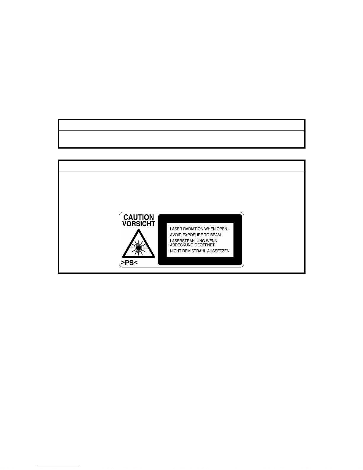
LASER SAFETY
The Center for Devices and Radiological Health (CDRH) prohibits the repair of
laser-based optical units in the field. The optical housing unit can only be repaired
in a factory or at a location with the requisite equipment. The laser subsystem is
replaceable in the field by a qualified Customer Engineer. The laser chassis is not
repairable in the field. Customer engineers are therefore directed to return all
chassis and laser subsystems to the factory or service depot when replacement of
the optical subsystem is required.
!WARNING
Use of controls, or adjustment, or performance of procedures other than
those specified in this manual may result in hazardous radiation exposure.
!WARNING
WARNING: Turn off the main switch before attempting any of the
procedures in the Laser Optics Housing Unit section. Laser
beams can seriously damage your eyes.
CAUTION MARKING:
Page 4
Trademarks
Microsoft
®
, Windows®, and MS-DOS® are registered trademarks of Microsoft
Corporation in the United States and /or other countries.
PostScript
®
is a registered trademark of Adobe Systems, Incorporated.
PCL
®
is a registered trademark of Hewlett-Packard Company.
Ethernet
®
is a registered trademark of Xerox Corporation.
PowerPC
®
is a registered trademark of International Business Machines
Corporation.
Other product names used herein are for identification purposes only and may be
trademarks of their respective companies. We disclaim any and all rights involved
with those marks.
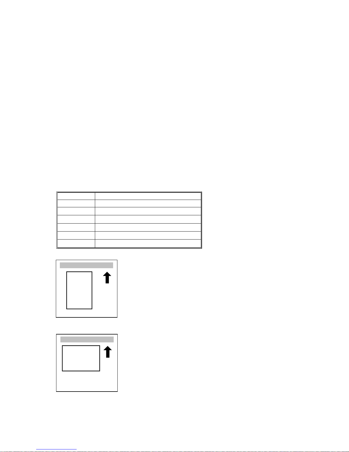
Conventions in this Manual
This manual uses several symbols.
Symbol What it means
☛ Refer to section number
!
See Core Tech Manual for details
"
Screw
#
Connector
$%
Clip ring
&%
E-ring
Lengthwise, SEF (Short Edge Feed)
Sideways, LEF (Long Edge Feed)
Page 5

i
TABLE OF CONTENTS
1. INSTALLATION...........................................................................1-1
1.1 INSTALLATION REQUIREMENTS...........................................................1-1
1.1.1 ENVIRONMENT .............................................................................. 1-1
1.1.2 MACHINE LEVEL............................................................................ 1-1
1.1.3 POWER REQUIREMENTS.............................................................. 1-2
1.1.4 SPACE REQUIREMENTS............................................................... 1-2
1.2 COPIER (B051/B052)............................................................................... 1-3
1.2.1 POWER SOCKETS FOR PERIPHERALS....................................... 1-3
1.2.2 INSTALLATION FLOW CHART....................................................... 1-4
1.2.3 ACCESSORY CHECK..................................................................... 1-5
1.2.4 INSTALLATION PROCEDURE........................................................ 1-6
1.3 PAPER TRAY UNIT (B456).................................................................... 1-13
1.3.1 ACCESSORY CHECK................................................................... 1-13
1.3.2 INSTALLATION PROCEDURE...................................................... 1-13
1.4 LCT (B457)............................................................................................. 1-17
1.4.1 ACCESSORY CHECK................................................................... 1-17
1.4.2 INSTALLATION PROCEDURE...................................................... 1-17
1.5 AUTO REVERSE DOCUMENT FEEDER (B386)................................... 1-21
1.5.1 ACCESSORY CHECK................................................................... 1-21
1.5.2 INSTALLATION PROCEDURE...................................................... 1-21
1.6 INTERCHANGE UNIT (B481)................................................................. 1-24
1.6.1 ACCESSORY CHECK................................................................... 1-24
1.6.2 INSTALLATION PROCEDURE...................................................... 1-25
1.7 1-BIN TRAY UNIT (B480)....................................................................... 1-26
1.7.1 ACCESORY CHECK..................................................................... 1-26
1.7.2 INSTALLATION PROCEDURE...................................................... 1-27
1.8 SHIFT TRAY........................................................................................... 1-30
1.8.1 COMPONENT CHECK.................................................................. 1-30
1.8.2 INSTALLATION PROCEDURE...................................................... 1-30
1.9 BY-PASS FEED UNIT (B490)................................................................. 1-33
1.9.1 ACCESSORY CHECK................................................................... 1-33
1.9.2 INSTALLATION PROCEDURE...................................................... 1-33
1.10 DUPLEX UNIT (B509).......................................................................... 1-35
1.10.1 ACCESSORY CHECK................................................................. 1-35
1.10.2 INSTALLATION PROCEDURE.................................................... 1-36
1.11 BRIDGE UNIT (B482) ........................................................................... 1-38
1.11.1 ACCESSORY CHECK................................................................. 1-38
1.11.2 INSTALLATION PROCEDURE.................................................... 1-38
1.12 1000-SHEET FINISHER (B408)........................................................... 1-41
1.12.1 ACCESSORY CHECK................................................................. 1-41
1.12.2 INSTALLATION PROCEDURE.................................................... 1-42
1.13 500-SHEET FINISHER (B458)............................................................. 1-45
1.13.1 ACCESSORY CHECK................................................................. 1-45
1.13.2 INSTALLATION PROCEDURE.................................................... 1-46
1.14 PLATEN COVER INSTALLATION........................................................ 1-48
Page 6

ii
1.15 MEMORY.............................................................................................. 1-49
1.16 KEY COUNTER INSTALLATION..........................................................1-51
1.17 ANTI-CONDENSATION HEATER........................................................ 1-53
1.18 TRAY HEATER..................................................................................... 1-54
1.19 TRAY HEATER (OPTIONAL PAPER TRAY UNIT) .............................. 1-55
1.20 TRAY HEATER (OPTIONAL LCT)........................................................ 1-57
2. PREVENTIVE MAIN TENANCE...................................................2-1
2.1 MAIN UNIT ............................................................................................... 2-1
2.1.1 OVERVIEW...................................................................................... 2-1
2.1.2 PM TABLE....................................................................................... 2-2
2.2 OPTIONAL UNIT PM TABLE.................................................................... 2-5
3. REPLACEMENT A ND ADJUSTMENT........................................ 3-1
3.1 SPECIAL TOOLS................................................................................ 3-1
3.2 FILTERS................................................................................................... 3-1
3.3 SCANNER UNIT....................................................................................... 3-2
3.3.1 EXPOSURE GLASS........................................................................ 3-2
3.3.2 APS SENSORS............................................................................... 3-2
3.3.3 LENS BLOCK ASSEMBLY.............................................................. 3-3
3.3.4 EXPOSURE LAMP STABILIZER..................................................... 3-5
3.3.5 SCANNER LAMP............................................................................. 3-5
3.3.6 SCANNER I/O BOARD.................................................................... 3-7
3.3.7 SCANNER MOTOR......................................................................... 3-7
3.3.8 FRONT SCANNER WIRE................................................................ 3-7
3.3.9 REAR SCANNER WIRE................................................................ 3-10
3.4 LASER UNIT........................................................................................... 3-12
3.4.1 CAUTION DECAL LOCATION....................................................... 3-12
3.4.2 LASER UNIT.................................................................................. 3-13
Adjusting for Image Skew .................................................................. 3-15
D-Phase Adjustment.......................................................................... 3-16
Laser Beam Pitch Adjustment............................................................ 3-17
3.4.3 POLYGONAL MIRROR MOTOR AND LSD...................................3-18
3.5 DEVELOPMENT UNIT........................................................................... 3-19
3.6 PHOTOCONDUCTOR UNIT (PCU)........................................................ 3-20
3.6.1 PCU ASSEMBLY........................................................................... 3-20
3.6.2 WASTE TONER BOTTLES........................................................... 3-21
3.6.3 CHARGE CORONA UNIT, GRID, WIRE, AND CLEANER............ 3-22
3.6.4 CHARGE CORONA WIRE CLEANER MOTOR............................ 3-23
3.6.5 OPC BELT CLEANING UNIT......................................................... 3-23
3.6.6 IMAGE TRANSFER BELT CLEANING UNIT................................. 3-23
3.7 PAPER TRANSFER UNIT...................................................................... 3-24
3.7.1 VERTICAL TRANSPORT UNIT..................................................... 3-24
3.7.2 TRANSFER ROLLER.................................................................... 3-24
3.8 FUSING/PAPER EXIT............................................................................ 3-25
3.8.1 FUSING UNIT................................................................................ 3-25
3.8.2 OIL SUPPLY UNIT......................................................................... 3-25
3.8.3 OIL SUPPLY PAD.......................................................................... 3-26
3.8.4 CLEANING ROLLER AND FUSING SPONGE ROLLER............... 3-26
Page 7

iii
3.8.5 OILING ROLLER AND OIL SUPPLY ROLLER.............................. 3-27
3.8.6 FUSING LAMPS............................................................................ 3-28
3.8.7 FUSING INNER UNIT.................................................................... 3-29
3.8.8 PRESSURE ROLLER THERMOFUSE.......................................... 3-29
3.8.9 HOT ROLLER STRIPPERS........................................................... 3-30
3.8.10 FUSING BELT UNIT AND PRESSURE ROLLER UNIT.............. 3-30
3.8.11 PRESSURE ROLLER, PRESSURE R OLLER G EAR,
AND CLEANING ROLLER........................................................... 3-31
3.8.12 PRESSURE ROLLER THERMISTOR......................................... 3-32
3.8.13 OIL ABSORBERS........................................................................ 3-33
3.8.14 PAPER EXIT/OVERFLOW SENSORS........................................ 3-34
3.9 PAPER FEED AND TRANSPORT ......................................................... 3-36
3.9.1 FEED ROLLER AND FRICTION PAD........................................... 3-36
3.9.2 REGISTRATION SENSOR............................................................ 3-37
3.9.3 PAPER FEED SENSOR 1............................................................. 3-40
3.9.4 PAPER NEAR-END SENSORS..................................................... 3-40
3.9.5 PAPER FEED SENSOR 2............................................................. 3-41
3.9.6 PAPER END SENSOR 1............................................................... 3-42
3.9.7 PAPER END SENSOR 2............................................................... 3-42
3.10 ELECTRICAL COMPONENTS............................................................. 3-43
3.10.1 EXHAUST FAN AND I/O BOARD................................................ 3-43
3.10.2 EX I/O BOARD............................................................................. 3-43
3.10.3 BICU BOARD AND CONTROLLER BOARD............................... 3-44
3.10.4 HDD............................................................................................. 3-45
3.10.5 HIGH VOLTAGE SUPPLY BOARD............................................. 3-45
3.10.6 POWER SUPPLY UNIT............................................................... 3-46
3.11 DRIVE UNITS....................................................................................... 3-47
3.11.1 DEVELOPMENT CLUTCHES...................................................... 3-47
K and Y Development Units............................................................... 3-47
C and M Development Units.............................................................. 3-47
3.11.2 DEVELOPMENT MOTOR............................................................ 3-48
3.11.3 MAIN MOTOR.............................................................................. 3-48
3.11.4 PCU GEAR BOX.......................................................................... 3-49
3.11.5 FUSING UNIT MOTOR................................................................ 3-49
3.11.6 PAPER FEED CLUTCH 1............................................................ 3-50
3.11.7 PAPER FEED MOTOR ................................................................ 3-50
3.11.8 PAPER FEED CLUTCH 2............................................................ 3-51
3.11.9 REGISTRATION CLUTCH........................................................... 3-51
3.11.10 OIL PUMP.................................................................................. 3-52
3.12 COPY ADJUSTMENT........................................................................... 3-53
3.12.1 PRINTING.................................................................................... 3-53
Registration - Leading Edge/Side-to-Side.......................................... 3-53
Blank Margin...................................................................................... 3-54
Main Scan Magnification.................................................................... 3-54
3.12.2 SCANNING.................................................................................. 3-55
Scanner Sub-Scan Magnification....................................................... 3-55
Scanner Leading Edge and Side-to-Side Registration....................... 3-55
Main Scan Dot Position Correction.................................................... 3-56
3.12.3 ARDF IMAGE ADJUSTMENT...................................................... 3-57
Page 8

i
v
ARDF Side-to-Side and Leading Edge Registration........................... 3-57
ARDF Skew Adjustment..................................................................... 3-58
3.13 COLOR ADJUSTMENT........................................................................ 3-59
3.13.1 AUTO COLOR CALIBRATION (ACC) ......................................... 3-59
3.13.2 PRINTER GAMMA CORRECTION.............................................. 3-60
Copy Mode......................................................................................... 3-60
Printer Mode....................................................................................... 3-64
3.14 SCANNER WHITE LEVEL ADJUSTMENT........................................... 3-66
White Level Check............................................................................. 3-66
White Level Adjustment..................................................................... 3-66
3.15 TOUCH SCREEN CALIBRATION........................................................ 3-69
4. TROUBLESHOOTIN G.................................................................4-1
4.1 SERVICE CALL........................................................................................ 4-1
4.1.1 SERVICE CALL CONDITIONS........................................................ 4-1
4.1.2 SC TABLE........................................................................................ 4-2
4.2 SELF-DIAGNOSTIC MODE.................................................................... 4-18
4.2.1 OVERVIEW.................................................................................... 4-18
4.2.2 DETAILED SELF-DIAGNOSTICS.................................................. 4-19
4.3 IMAGE TEST MODE .............................................................................. 4-20
4.3.1 OVERVIEW.................................................................................... 4-20
4.3.2 VPU TEST..................................................................................... 4-20
SP4-907-1: VPU Test Pattern: R........................................................ 4-20
SP4-907-2: VPU Test Pattern: G....................................................... 4-20
SP4-907-3: VPU Test Pattern: B........................................................ 4-20
4.3.3 IPU TEST....................................................................................... 4-20
SP4-904-1 Register Write/Read Check Result................................... 4-20
SP4-904-2 Image Path Check Result ................................................ 4-20
4.3.4 GAVD TEST................................................................................... 4-20
4.4 ELECTRICAL COMPONENT DEFECTS................................................ 4-21
4.4.1 SENSORS..................................................................................... 4-21
4.4.2 SWITCHES.................................................................................... 4-23
4.4.3 BLOWN FUSE CONDITIONS........................................................ 4-23
4.5 CHECK POINTS FOR IMAGE PROBLEMS AT REGULAR
INTERVALS............................................................................................ 4-24
5. SERVICE TABLES......................................................................5-1
5.1 SERVICE PROGRAM MODE................................................................... 5-1
5.1.1 SERVICE PROGRAM MODE OPERATION.................................... 5-1
Starting the SP mode........................................................................... 5-1
Quitting the SP mode........................................................................... 5-1
SP Mode Touch Screen....................................................................... 5-2
Copy Window for Test Printing............................................................. 5-3
Working on SP Mode Menus................................................................ 5-3
5.1.2 SP MODE TABLE............................................................................ 5-4
SP1-XXX: (Feed) ................................................................................. 5-4
SP2-XXX: (Drum)................................................................................. 5 -8
SP3-XXX: (Process)........................................................................... 5-21
SP4-XXX: (Scanner) .......................................................................... 5-25
Page 9

v
SP5-XXX: (Mode)............................................................................... 5 -29
SP6-XXX: (Peripherals) ..................................................................... 5-47
SP7-XXX: (Data Log)......................................................................... 5-50
SP9-XXX: (Etc.) ................................................................................. 5-62
5.1.3 TEST PATTERN PRINTING (SP5-955-1)...................................... 5-63
5.1.4 INPUT CHECK............................................................................... 5-64
Main Machine Input Check (SP5-803)............................................... 5-64
Table 1: Tray 1 and 2 Paper Size....................................................... 5-67
Table 2: By-pass Tray Paper Size...................................................... 5-67
Table 3: Optional Paper Tray Unit Paper Size................................... 5-67
Table 4: Optional Paper Tray Unit Paper Near End........................... 5-67
ARDF Input Check (SP6-007)............................................................ 5-68
Finisher Input Check (SP6-117)......................................................... 5-69
5.1.5 OUTPUT CHECK........................................................................... 5-70
Main Machine Output Check (SP5-804)............................................. 5-70
ARDF Output Check (SP6-008)......................................................... 5-73
Finisher Output Check (SP6-118)...................................................... 5-73
5.1.6 SMC DATA LISTS (SP5-990)........................................................ 5-74
5.1.7 ORIGINAL JAM HISTORY DISPLAY............................................. 5-74
Total Count......................................................................................... 5-74
Details on the Most Recent Jams....................................................... 5-74
5.1.8 COPY JAM HISTORY DISPLAY.................................................... 5-75
Total Count......................................................................................... 5-75
Details on the Most Recent Jams....................................................... 5-75
5.1.9 MEMORY ALL CLEAR (SP5-801)................................................. 5-76
Using a Flash Memory Card............................................................... 5-76
Without Using a Flash Memory Card ................................................. 5-77
5.1.10 APS OUTPUT DISPLAY (SP4-301)............................................. 5-78
5.2 PROGRAM DOWNLOAD....................................................................... 5-79
5.2.1 FIRMWARE................................................................................... 5-79
5.2.2 NVRAM DATA UPLOAD/DOWNLOAD.......................................... 5-80
Uploading NVRAM Data (SP5-824)................................................... 5-80
Downloading NVRAM Data (SP5-825)............................................... 5-81
5.3 SOFTWARE RESET............................................................................... 5-82
5.4 SYSTEM SETTINGS AND COPY SETTING RESET............................. 5-82
5.4.1 SYSTEM SETTING RESET........................................................... 5-82
5.4.2 COPIER SETTING RESET............................................................ 5-83
5.5 USER TOOLS......................................................................................... 5-84
5.5.1 HOW TO ENTER USER TOOLS................................................... 5-84
UP Mode Initial Screen: User Tools/Counter Display......................... 5-84
System Settings................................................................................. 5-84
Copier/Document Server Features..................................................... 5-84
Printer, Facsimile, Scanner Settings.................................................. 5-84
Inquiry................................................................................................ 5-84
Counter.............................................................................................. 5-85
5.6 DIP SWITCHES...................................................................................... 5-85
Page 10

vi
6. DETAILED SECTION DESCRIPTIONS.......................................6-1
6.1 OVERVIEW .............................................................................................. 6-1
6.1.1 MECHANICAL COMPONENTS....................................................... 6-1
6.1.2 PAPER PATH.................................................................................. 6-2
6.1.3 DRIVE COMPONENTS................................................................... 6-3
Layout.................................................................................................. 6-3
Drive Power Path................................................................................. 6-4
6.1.4 ELECTRICAL COMPONENTS........................................................ 6-5
Scanner Unit........................................................................................ 6-5
Image Transfer..................................................................................... 6-6
Paper Path........................................................................................... 6-7
Development Units............................................................................... 6-8
Boards.................................................................................................. 6-9
6.2 BOARD STRUCTURE............................................................................ 6-10
6.2.1 BLOCK DIAGRAM......................................................................... 6-10
6.2.2 CONTROLLER.............................................................................. 6-12
6.3 COPY PROCESS................................................................................... 6-14
6.4 PROCESS CONTROL............................................................................ 6-16
6.4.1 OVERVIEW.................................................................................... 6-16
6.4.2 PROCESS CONTROL STEPS...................................................... 6-16
Six Steps............................................................................................ 6-16
When is Process Control Done?........................................................ 6-16
Supplementary Information on Pr ocess Control................................. 6-17
6.5 SCANNING............................................................................................. 6-19
6.5.1 OVERVIEW.................................................................................... 6-19
6.5.2 SCANNER DRIVE ......................................................................... 6-20
Book Mode......................................................................................... 6-20
ARDF Mode ....................................................................................... 6-20
6.5.3 ORIGINAL SIZE DETECTION....................................................... 6-21
6.6 IMAGE PROCESSING ........................................................................... 6-23
6.6.1 OVERVIEW.................................................................................... 6-23
6.6.2 SBU BLOCK DIAGRAM................................................................. 6-24
Signal Processing .............................................................................. 6-24
A/D Conversion.................................................................................. 6-24
White Level Correction ....................................................................... 6-24
Others................................................................................................ 6-24
Black Level Correction....................................................................... 6-25
VPU Test Mode.................................................................................. 6-25
6.6.3 IMAGE PROCESSING .................................................................. 6-26
Shading Correction............................................................................ 6-26
Picture Element (Dot Position) Correction.......................................... 6-26
Scan Line Correction.......................................................................... 6-26
Scanner Gamma Correction (RGB Gamma Correction).................... 6-27
Filtering.............................................................................................. 6-27
ADS (Auto Image Density Selection) ................................................. 6-27
Image Separation............................................................................... 6-28
ACS (Auto Color Selection)................................................................ 6-28
Color Conversion ............................................................................... 6-29
Page 11

vii
Main Scan Magnification.................................................................... 6-29
Printer Gamma Correction................................................................. 6-30
Error Diffusion.................................................................................... 6-32
ASICs on the BICU Board Test.......................................................... 6-32
6.7 PHOTOCONDUCTOR UNIT (PCU)........................................................ 6-33
6.7.1 OVERVIEW.................................................................................... 6-33
6.7.2 CHARGE CORONA UNIT.............................................................. 6-34
Power Supply..................................................................................... 6-34
Grid and Wire Cleaning...................................................................... 6-34
Quenching.......................................................................................... 6-35
6.7.3 OPC BELT DRIVE......................................................................... 6-35
6.7.4 OPC BELT CLEANING UNIT......................................................... 6-36
Bottle Detection.................................................................................. 6-36
Waste Toner Collection...................................................................... 6-36
Drive................................................................................................... 6-37
6.7.5 IMAGE TRANSFER BELT UNIT.................................................... 6-37
Drive................................................................................................... 6-37
Belt Mark Detection............................................................................ 6-38
Transfer Roller................................................................................... 6-38
6.7.6 IMAGE TRANSFER BELT CLEANING UNIT................................. 6-39
Image Transfer Belt Cleaning............................................................. 6-39
Waste Toner Collection...................................................................... 6-39
Set Switch and Full Sensor................................................................ 6-39
Contact Mechanism ........................................................................... 6-40
Power Supply..................................................................................... 6-41
Drive................................................................................................... 6-41
6.8 LASER EXPOSURE............................................................................... 6-42
6.8.1 OVERVIEW.................................................................................... 6-42
6.8.2 POLYGON MIRROR MOTOR UNIT.............................................. 6-43
Speed................................................................................................. 6-43
6.8.3 SYNCHRONIZATION DETECTOR................................................ 6-43
6.8.4 LD UNIT......................................................................................... 6-43
6.8.5 LD SAFETY SWITCH.................................................................... 6-44
Front Door.......................................................................................... 6-44
Circuit................................................................................................. 6-44
Operation Panel Display and Switch Mechanism............................... 6-45
6.9 DEVELOPMENT..................................................................................... 6-46
6.9.1 OVERVIEW.................................................................................... 6-46
6.9.2 DEVELOPMENT UNIT .................................................................. 6-47
Replacing Units.................................................................................. 6-47
Memory Chip...................................................................................... 6-47
6.9.3 TONER SUPPLY MECHANISM.................................................... 6-48
Drive................................................................................................... 6-48
Rollers and Agitators.......................................................................... 6-49
Shutter ............................................................................................... 6-49
6.9.4 TONER END DETECTION............................................................ 6-50
Mechanism......................................................................................... 6-50
Toner Near-End Detection................................................................. 6-50
Toner End Detection.......................................................................... 6-51
Page 12

viii
Toner End Recovery.......................................................................... 6-51
6.9.5 DEVELOPMENT UNIT CONTACT MECHANISM......................... 6-52
Mechanism......................................................................................... 6-52
Reverse Rotation ............................................................................... 6-52
6.9.6 POWER SOURCE......................................................................... 6-53
Development, Toner Supply, and Doctor Rollers............................... 6-53
Doctor Roller...................................................................................... 6-53
6.10 PAPER FEED....................................................................................... 6-54
6.10.1 OVERVIEW.................................................................................. 6-54
Transport Speed................................................................................ 6-55
Friction Pad........................................................................................ 6-55
6.10.2 DRIVE MECHANISM................................................................... 6-55
Feed and Vertical Transport............................................................... 6-55
Registration........................................................................................ 6-55
6.10.3 PAPER LIFT................................................................................ 6-56
Lift Mechanism................................................................................... 6-56
Paper End/Near-End Detection.......................................................... 6-56
6.10.4 PAPER SIZE DETECTION.......................................................... 6-57
Mechanism......................................................................................... 6-57
Switch Pattern.................................................................................... 6-57
6.11 PAPER TRANSFER AND SEPARATION............................................. 6-58
6.11.1 OVERVIEW.................................................................................. 6-58
Jammed Paper Release..................................................................... 6-58
Image Transfer and Paper Separation............................................... 6-58
6.11.2 CONTACT/SEPARATION MECHANISM..................................... 6-59
Timing................................................................................................ 6-59
Mechanism......................................................................................... 6-59
6.11.3 POWER SUPPLY........................................................................ 6-60
Circuit................................................................................................. 6-60
Paper Transfer Roller Bias................................................................. 6-60
Discharge Plate.................................................................................. 6-60
Temperature/Humidity Control........................................................... 6-60
Roller Cleaning................................................................................... 6-61
6.12 IMAGE FUSING AND PAPER EXIT..................................................... 6-62
6.12.1 OVERVIEW.................................................................................. 6-62
6.12.2 DRIVE.......................................................................................... 6-63
6.12.3 FUSING UNIT COMPONENTS ................................................... 6-64
Fusing Belt......................................................................................... 6-64
Heating Roller Lamp .......................................................................... 6-64
Pressure Roller Lamp ........................................................................ 6-64
Pressure Roller Pawls........................................................................ 6-64
Fusing Bias........................................................................................ 6-65
Fusing Unit SCs................................................................................. 6-65
6.12.4 OIL SUPPLY................................................................................ 6-66
Oil Supply........................................................................................... 6-66
Oil Supply........................................................................................... 6-67
Oil End Detection and Recovery........................................................ 6-68
6.12.5 TEMPERATURE CONTROL....................................................... 6-69
6.12.6 ENERGY SAVER MODES........................................................... 6-70
Page 13

ix
Overview............................................................................................ 6-70
Panel Off Mode.................................................................................. 6-71
Low Power Mode............................................................................... 6-72
Auto Off Mode.................................................................................... 6-73
6.12.7 PAPER EXIT................................................................................ 6-74
Drive................................................................................................... 6-74
Paper Jam Detection.......................................................................... 6-74
6.12.8 PAPER OVERFLOW DETECTION.............................................. 6-74
PERIPHERALS
PAPER TRAY UNIT (B456)
1. REPLACEMENT AND ADJUSTMENT..................................B456-1
1.1 REAR COVER....................................................................................B456-1
1.2 PAPER FEED CLUTCHES.................................................................B456-1
1.3 LIFT MOTORS....................................................................................B456-2
1.4 PAPER FEED MOTOR.......................................................................B456-2
1.5 CONTROLLER BOARD......................................................................B456-2
1.6 PAPER FEED UNIT............................................................................B456-3
1.7 PICKUP, FEED, AND SEPARATION ROLLERS................................B456-4
1.8 UPPER LIMIT, PAPER END, AND RELAY SENSORS...................... B456-4
2. DETAILED DESCRIPTIONS.................................................B456-5
2.1 MECHANICAL COMPONENT LAYOUT.............................................B456-5
2.2 ELECTRICAL COMPONENT LAYOUT..............................................B456-6
2.3 PAPER FEED..................................................................................... B456-7
Paper Feed Mechanism.................................................................B456-7
Drive Path......................................................................................B456-7
2.4 PAPER SIZE DETECTION.................................................................B456-8
2.5 REVERSE ROLLER AND PICK-UP ROLLER RELEASE...................B456-9
2.6 PAPER LIFT.....................................................................................B456-10
2.7 PAPER HEIGHT AND END DETECTION........................................B456-11
Paper Height Detection................................................................B456-11
Paper End and Bottom Plate........................................................B456-12
LCT (B457)
1. REPLACEMENT AND ADJUSTMENT..................................B457-1
1.1 TRAY..................................................................................................B457-1
1.2 SENSORS..........................................................................................B457-2
Paper Height Sensors of Paper Storage Side................................B457-2
Left Fence HP Sensor/Paper End Sensor 2...................................B457-2
1.3 CHANGING THE TRAY SIZE.............................................................B457-3
1.4 TRAY LIFT MOTOR............................................................................B457-3
1.5 TRAY MOTOR .................................................................................... B457-4
1.6 MAIN BOARD..................................................................................... B457-4
Page 14

x
1.7 STACK TRANSPORT CLUTCH.........................................................B457-5
1.8 PAPER FEED CLUTCH......................................................................B457-5
1.9 PAPER FEED UNIT............................................................................B457-6
1.10 PICKUP, FEED, AND SEPARATION ROLLERS..............................B457-7
1.11 UPPER LIMIT, PAPER END 1, AND RELAY SENSORS................B457-7
2. DETAILED DESCRIPTIONS.................................................B457-8
2.1 MECHANICAL COMPONENT LAYOUT.............................................B457-8
2.2 ELECTRICAL COMPONENT LAYOUT..............................................B457-9
2.3 ELECTRICAL COMPONENT DESCRIPTIONS................................B457-10
2.4 PAPER FEED................................................................................... B457-11
2.5 SEPARATION ROLLER AND PICKUP ROLLER RELEASE............B457-12
2.6 TRAY LIFT........................................................................................B457-13
2.7 PAPER AMOUNT DETECTION ....................................................... B457-14
2.8 PAPER END DETECTION OF PAPER FEED SIDE.........................B457-15
2.9 PAPER STACK TRANSPORT..........................................................B457-16
AUTO REVERSE DOCUMENT FEEDER (B386)
1. REPLACEMENT AND ADJUSTMENT..................................B386-1
1.1 DF EXIT TABLE AND COVERS.........................................................B386-1
1.2 ORIGINAL FEED UNIT.......................................................................B386-2
1.3 LEFT COVER.....................................................................................B386-2
1.4 PICK-UP ROLLER..............................................................................B386-3
1.5 FEED BELT........................................................................................B386-3
1.6 SEPARATION ROLLER.....................................................................B386-4
1.7 ORIGINAL SET/ORIGINAL REVERSE SENSORS............................B386-4
1.8 ORIGINAL SIZE SENSORS, TRAILING EDGE SENSOR..................B386-5
1.9 ORIGINAL FEED DRIVE....................................................................B386-6
DF Feed Clutch..............................................................................B386-6
Pick-up Solenoid............................................................................B386-6
Transport Motor..............................................................................B386-6
DF Feed Motor...............................................................................B386-6
1.10 REGISTRATION SENSOR...............................................................B386-7
1.11 STAMP SOLENOID AND ORIGINAL EXIT SENSOR......................B386-8
2. DETAILED DESCRIPTIONS.................................................B386-9
2.1 MECHANICAL COMPONENT LAYOUT.............................................B386-9
2.2 ELECTRICAL COMPONENT LAYOUT............................................ B386-10
2.3 ELECTRICAL COMPONENT DESCRIPTION..................................B386-11
2.4 DRIVE LAYOUT ...............................................................................B386-12
2.5 ORIGINAL SIZE DETECTION..........................................................B386-13
2.6 MIXED ORIGINAL SIZE MODE........................................................B386-16
2.7 PICK-UP AND SEPARATION...........................................................B386-17
2.8 ORIGINAL TRANSPORT AND EXIT................................................B386-18
2.8.1 SINGLE-SIDED ORIGINALS...................................................B386-18
2.8.2 DOUBLE-SIDED ORIGINALS..................................................B386-19
2.8.3 ORIGINAL TRAILING EDGE SENSOR...................................B386-20
Page 15

xi
2.9 STAMP ............................................................................................. B386-21
2.10 TIMING CHART..............................................................................B386-22
2.11 CONDITION OF JAM DETECTION................................................B386-23
2.12 OVERALL ELECTRICAL CIRCUIT.................................................B386-24
3. SERVICE TABLES..............................................................B386-25
3.1 DIP SWITCHES................................................................................B386-25
INTERCHANGE UNIT (B418)
1. REPLACEMENT AND ADJUSTMENT..................................B481-1
1.1 EXIT SENSOR REPLACEMENT........................................................B481-1
2. DETAILED DESCRIPTION....................................................B481-2
2.1 MECHANICAL COMPONENT LAYOUT.............................................B481-2
2.2 ELECTRICAL COMPONENT AND DRIVE LAYOUT..........................B481-3
2.3 JUNCTION GATE MECHANISM........................................................B481-4
To the Exit Tray or Bridge Unit (for the Upper Tray on top of the Bridge
Unit, or the Finisher).......................................................................B481-4
To the 1-bin Tray............................................................................B481-4
To the Duplex Unit ......................................................................... B481-4
1-BIN TRAY UNIT (B480)
1. REPLACEMENT AND ADJUSTMENT..................................B480-1
1.1 PAPER SENSOR REMOVAL.............................................................B480-1
2. DETAILED DESCRIPTION....................................................B480-2
2.1 MECHANICAL COMPONENT LAYOUT.............................................B480-2
2.2 ELECTRICAL COMPONENT LAYOUT..............................................B480-3
2.3 ELECTRICAL COMPONENT DESCRIPTION....................................B480-3
2.4 BASIC OPERATION...........................................................................B480-4
SHIFT TRAY UNIT (B510)
1. REPLACEMENT AND ADJUSTMENT..................................B510-1
1.1 TRAY COVER REPLACEMENT.........................................................B510-1
1.1.1 TRAY COVER REMOVAL......................................................... B510-1
1.1.2 TRAY COVER ATTACHMENT..................................................B510-1
1.2 TRAY MOTOR AND HALF TURN SENSOR REPLACEMENT .......... B510-2
1.2.1 REPLACING THE TRAY MOTOR.............................................B510-2
1.2.2 REPLACING THE HALF TURN SENSOR ................................. B510-2
2. DETAILED DESCRIPTIONS.................................................B510-3
2.1 COMPONENT LAYOUT.....................................................................B510-3
2.2 BASIC OPERATION...........................................................................B510-4
2.3 PRIMARY MECHANISMS..................................................................B510-5
Page 16

xii
2.3.1 TRAY SHIFT..............................................................................B510-5
2.3.2 HALF TURN DETECTION.........................................................B510-6
BY-PASS TRAY UNIT (B490)
1. REPLACEMENT AND ADJUSTMENT..................................B490-1
1.1 PICKUP/FEED ROLLER.....................................................................B490-1
1.2 PAPER FEED CLUTCH......................................................................B490-2
1.3 REVERSE ROLLER...........................................................................B490-2
1.4 PAPER SIZE SENSOR BOARD.........................................................B490-3
2. DETAILED DESCRIPTIONS.................................................B490-4
2.1 MECHANICAL COMPONENT LAYOUT.............................................B490-4
2.2 PAPER FEED..................................................................................... B490-5
2.2.1 DRIVE........................................................................................B490-5
Power Source.................................................................................B490-5
Rollers............................................................................................B490-5
2.2.2 PAPER FEED MECHANISM.....................................................B490-6
Pickup Roller Mechanism...............................................................B490-6
Paper End Detection......................................................................B490-6
2.3 PAPER SIZE DETECTION.................................................................B490-7
DUPLEX UNIT (B509)
1. REPLACEMENT AND ADJUSTMENT..................................B509-1
1.1 EXTERIOR COVER............................................................................B509-1
1.2 ENTRANCE/EXIT SENSORS.............................................................B509-1
1.3 INVERTER MOTOR...........................................................................B509-2
1.4 CONTROLLER BOARD......................................................................B509-2
1.5 TRANSPORT MOTOR.......................................................................B509-2
2. DETAILED DESCRIPTIONS.................................................B509-3
2.1 OVERVIEW ........................................................................................B509-3
2.2 ELECTRICAL COMPONENT LAYOUT..............................................B509-4
2.3 DRIVE LAYOUT .................................................................................B509-5
2.4 DUPLEX PAPER FEED ORDER........................................................ B509-6
2.4.1 LONGER THAN A4/LT LEF....................................................... B509-6
2.4.2 UP TO A4/LT LEF......................................................................B509-7
2.5 REVERSE MECHANISM....................................................................B509-8
BRIDGE UNIT (B482)
1. REPLACEMENT AND ADJUSTMENT..................................B482-1
1.1 BRIDGE UNIT DRIVE MOTOR REPLACEMENT...............................B482-1
1.2 TRAY EXIT SENSOR REPLACEMENT.............................................B482-2
1.3 RELAY SENSOR REPLACEMENT....................................................B482-2
Page 17

xiii
2. DETAILED DESCRIPTIONS.................................................B482-3
2.1 MECHANICAL COMPONENT LAYOUT.............................................B482-3
2.2 DRIVE LAYOUT .................................................................................B482-4
2.3 ELECTRICAL COMPONENT LAYOUT..............................................B482-5
2.4 ELECTRICAL COMPONENT DESCRIPTION....................................B482-6
2.5 JUNCTION GATE MECHANISM........................................................B482-7
1000-SHEET FINISHER (B408)
1. REPLACEMENT AND ADJUSTMENT..................................B408-1
1.1 MAIN PCB ..........................................................................................B408-1
1.2 STAPLER UNIT..................................................................................B408-2
1.3 MOTORS............................................................................................B408-3
1.3.1 SHIFT MOTOR..........................................................................B408-3
1.3.2 STAPLER MOTOR....................................................................B408-3
1.3.3 UPPER TRANSPORT MOTOR AND EXIT MOTOR.................B408-4
1.3.4 LOWER TRANSPORT MOTOR................................................B408-4
1.4 MOTORS AND SENSORS.................................................................B408-5
1.4.1 PREPARATION.........................................................................B408-5
1.4.2 STACK HEIGHT SENSOR........................................................B408-6
1.4.3 STAPLER TRAY PAPER SENSOR...........................................B408-6
1.4.4 LOWER TRAY LIFT MOTOR.....................................................B408-7
1.4.5 STACK FEED-OUT MOTOR.....................................................B408-7
2. TROUBLESHOOTIN G...........................................................B408-8
2.1 JAM DETECTION...............................................................................B408-8
3. SERVICE TABLES................................................................B408-9
3.1 DIP SWITCH SETTINGS....................................................................B408-9
4. DETAILED DESCRIPTIONS...............................................B408-10
4.1 GENERAL LAYOUT.........................................................................B408-10
4.2 ELECTRICAL COMPONENT LAYOUT............................................ B408-11
4.3 ELECTRICAL COMPONENT DESCRIPTION..................................B408-13
4.4 DRIVE LAYOUT ...............................................................................B408-15
4.5 JUNCTION GATES...........................................................................B408-16
Upper Tray Mode.........................................................................B408-16
Sort/Stack Mode...........................................................................B408-16
Staple Mode.................................................................................B408-16
4.6 UPPER TRAY...................................................................................B408-17
4.7 LOWER TRAY UP/DOWN MECHANISMS.......................................B408-18
4.8 PAPER SHIFT MECHANISM ........................................................... B408-19
4.9 JOGGER UNIT PAPER POSITIONING MECHANISM ..................... B408-20
4.10 EXIT GUIDE PLATE.......................................................................B408-21
4.11 STAPLER MECHANISM.................................................................B408-22
4.12 STAPLER UNIT MOVEMENT MECHANISM..................................B408-23
4.13 PAPER FEED-OUT MECHANISM..................................................B408-24
Page 18

xi
v
500-SHEET FINISHER (B458)
1. REPLACEMENT AND ADJUSTMENT..................................B458-1
1.1 EXTERIOR .........................................................................................B458-1
Front Cover....................................................................................B458-2
1.2 ENTRANCE UPPER GUIDE/PAPER EXIT UNIT...............................B458-4
1.3 ENTRANCE LOWER GUIDE..............................................................B458-5
1.4 PAPER EXIT UNIT GEAR/PADDLE ROLLER SOLENOID................B458-5
1.5 STAPLER UNIT..................................................................................B458-6
1.6 JOGGER TRAY UNIT.........................................................................B458-6
1.7 PAPER EXIT SENSOR FEELER........................................................B458-7
1.8 MAIN MOTOR ....................................................................................B458-7
1.9 JOGGER MOTOR..............................................................................B458-8
1.10 CONTROL BOARD...........................................................................B458-8
1.11 OUTPUT TRAY UNIT.......................................................................B458-9
2. DETAILED DESCRIPTIONS...............................................B458-10
2.1 OVERALL MACHINE INFORMATION..............................................B458-10
2.1.1 COMPONENT LAYOUT..........................................................B458-10
Mechanical Component Layout....................................................B458-10
Drive Layout.................................................................................B458-11
2.1.2 ELECTRICAL COMPONENT LAYOUT...................................B458-12
2.1.3 ELECTRICAL COMPONENT DESCRIPTIONS.......................B458-13
2.2 DETAILED SECTION DESCRIPTIONS............................................B458-14
2.2.1 OUTPUT TRAY MECHANISM.................................................B458-14
Stack Height Detection.................................................................B458-14
Output Tray Up/Down Mechanism...............................................B458-15
2.2.2 PAPER FEED..........................................................................B458-16
Straight Feed Out Mode............................................................... B458-16
Shift Sorting Mode........................................................................B458-17
Stapling Mode..............................................................................B458-19
2.2.3 JAM CONDITIONS..................................................................B458-20
2.2.4 ERROR DETECTION...............................................................B458-20
SPECIFICATIONS
SPECIFICATIONS...................................................................... Spec-1
1. GENERAL SPECIFICATIONS (MAIN UNIT)........................................Spec-1
2. MACHINE CONFIGURATION.............................................................. Spec-3
2.1 SYSTEM COMPONENTS.............................................................Spec-3
2.2 OPTIONAL EQUIPMENT ............................................................. Spec-5
ARDF............................................................................................. Spec-5
Bridge Unit..................................................................................... Spec-5
By-pass Tray Unit...........................................................................Spec-6
Duplex Unit.....................................................................................Spec-6
Interchange Unit............................................................................. Spec-6
Page 19

x
v
LCT................................................................................................ Spec-7
Paper Tray Unit.............................................................................. Spec-7
Shift Tray Unit ................................................................................Spec-7
1-Bin Tray Unit............................................................................... Spec-8
500-Sheet Finisher......................................................................... Spec-8
1000-sheet Finisher ....................................................................... Spec-9
Upper Tray.....................................................................................Spec-9
Lower Tray.....................................................................................Spec-9
Page 20

26 July 2002 INSTALLATION REQUIREMENTS
1-1
Installation
1. INSTALLATION
1.1 INSTALLATION REQUIREMENTS
1.1.1 ENVIRONMENT
1. Temperature Range:
10°C to 32°C (50°F to 89.6°F) (humidity to be 54% at
32°C, 89.6°F)
2. Humidity Range:
15% to 80% Rh (temperature to be 27°C, 80.6°F at
80%)
3. Ambient Illumination: Less than 1,500 lux (keep the machine out of direct
sunlight.)
4. Ventilation: Air turnover of more than 30 m
3
/hr/person or more
5. Ambient Dust: Less than 0.10 mg/m
3
(2.7 x 10
– 6
oz/yd3)
6. Avoid exposing the machine to sudden temperature changes, which include:
1) Direct cool air from an air conditioner
2) Direct heat from a heater
7. Avoid installing the machine in areas that may be exposed to corrosive gas.
8. Install the machine at a location lower than 2,000 m (6,500 ft.) above sea level.
9. Install the machine on a strong, level base.
10. Avoid installing the machine in areas that may be subjecte d to strong vibration.
1.1.2 MACHINE LEVEL
Front to back: W ithin 5 mm (0.2") of level
Right to left: Within 5 mm (0.2") of level
Page 21
INSTALLATION REQUIREMENTS 26 July 2002
1-2
1.1.3 POWER REQUIREMENTS
!CAUTION
1. Insert the plug firmly in the outlet.
2. Avoid using an outlet extension plug or cord.
3. Ground the machine.
1. Input voltage level: 120 V, 60 Hz, More than 12 A
220 ∼ 240 V, 50/60 Hz, More than 8 A
110 V, 50/60 Hz, More than 13A
2. Permissible voltage fluctuation: ±10%
3. Do not put or place anything on the power cord.
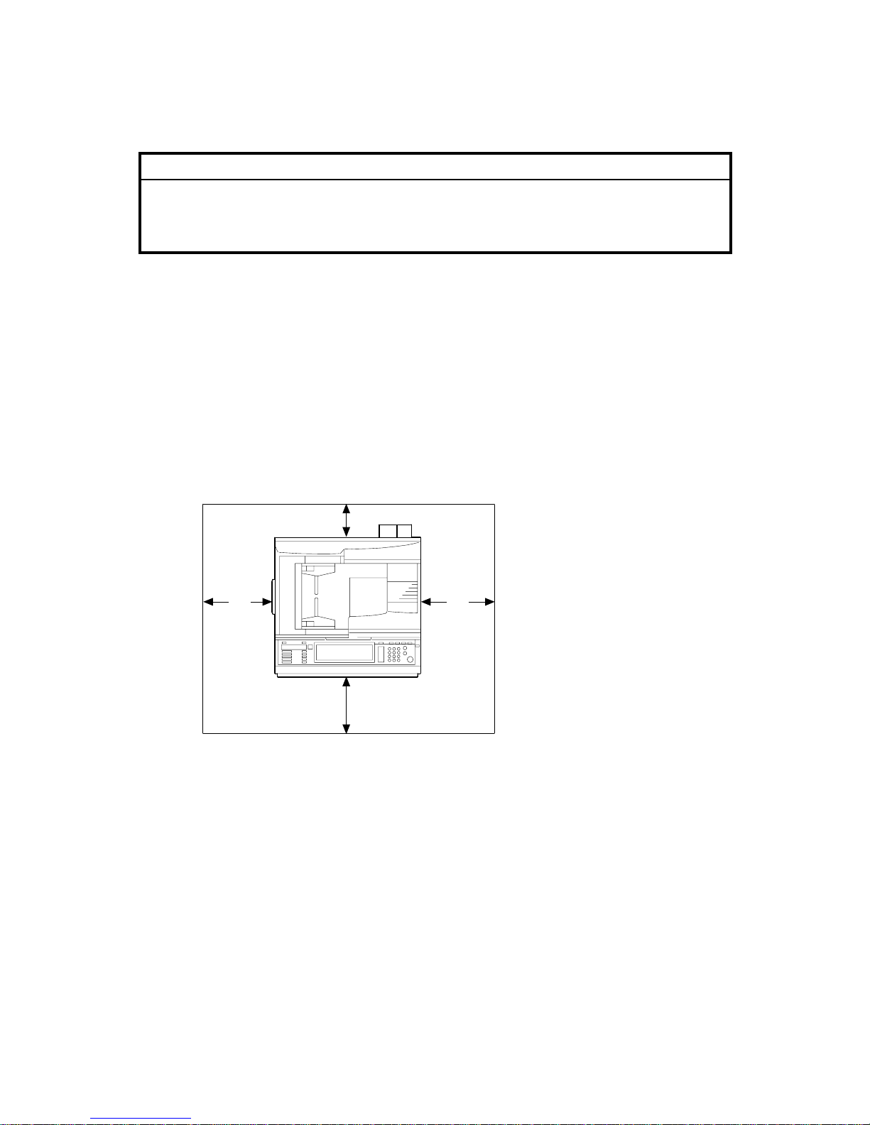
1.1.4 SPACE REQUIREMENTS
B051I126.WMF
A
: Over 100 mm (4")
B: Over 100 mm (4")
C: Over 550 mm (22")
D: Over 750 mm (29.6")
A C
B
D
Page 22
26 July 2002 COPIER (B051/B052)
1-3
Installation
1.2 COPIER (B051/B052)
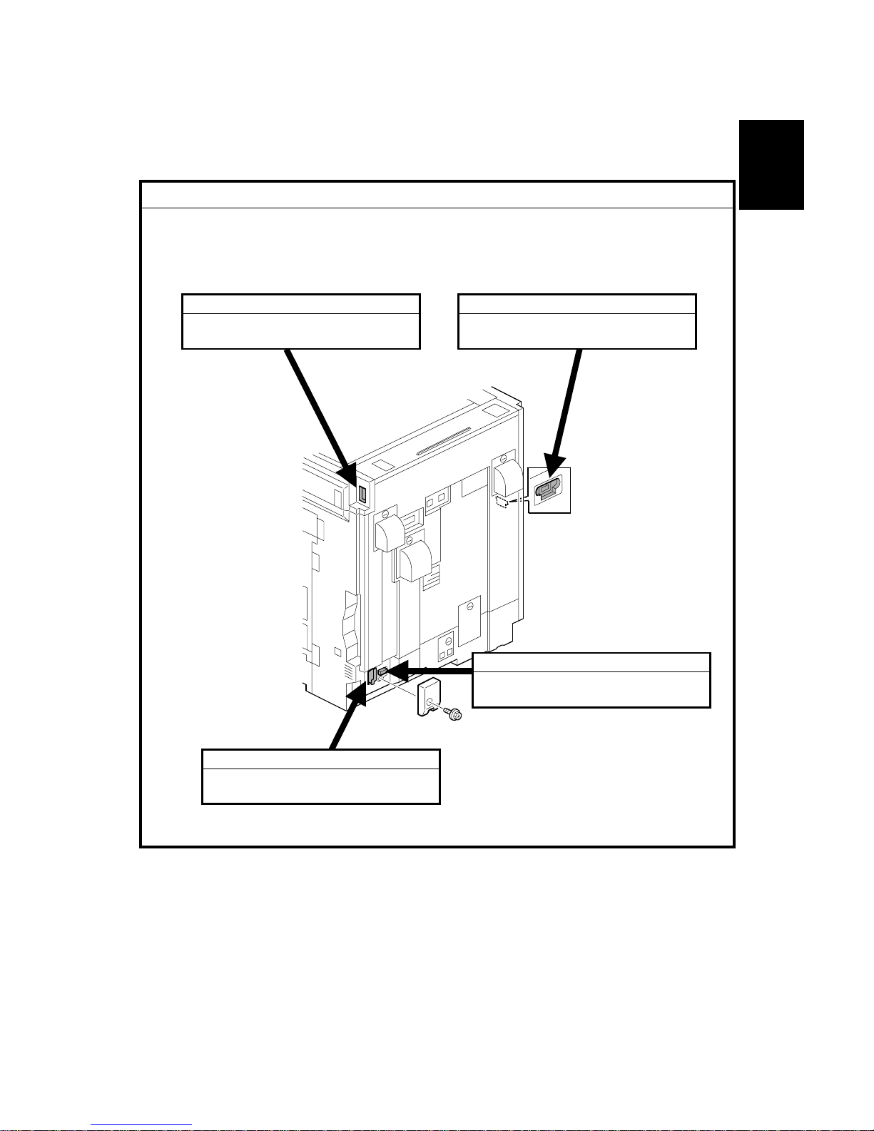
1.2.1 POWER SOCKETS FOR PERIPHERALS
!CAUTION
Rating voltage for peripherals.
Make sure to plug the cables into the correct sockets.
B051I130.WMF
1. ADF
1. Rating voltage output connector
for accessory Max. DC24 V
2. Finisher
1. Rating voltage output connector
for accessory Max. DC24 V
3. By-pass Tray
1. Rating voltage output connector
for accessory Max. DC24 V
4. Duplex Unit
1. Rating voltage output connector
for accessory Max. DC24 V
Page 23

COPIER (B051/B052) 26 July 2002
1-4
1.2.2 INSTALL ATION FLOW CHART
The following flow chart shows how to install the optional units more efficiently.
Unpack the copier
Place the copier on the Paper Tray Unit or LCT
Install the Paper Tray Unit or LCT
Install the copier
Install the Memory Unit
Install the By-pass Tray
Yes No
Yes No
Yes No
Install the Interchange Unit
Install the Duplex Unit and/or 1-bi n Tray U nit
Yes No
Install the Shift Tray
Yes No
Install the Bridge Unit
Install the Finisher
Yes No
Does the user require the Paper Tray Unit, LCT, or Finisher?
Does the user require the Memory Unit
Does the user require the By-pass Tray ?
Install the ARDF or Platen Cover (if required)
Does the user require the Duplex Unit and/or 1-bin Tray Unit ?
Does the user require the Shift Tray?
Does the user require the Finisher?
B051I500.WMF
Page 24

26 July 2002 COPIER (B051/B052)
1-5
Installation
1.2.3 ACCESSORY CHECK
Check the quantity and condition of the accessories in the box against the following
list:
No. Description Q’ty
1 Paper Tray Decal 1
2 Model Name Decal 1
3 NECR 1
4 Factory Data Sheet 1
5 Filter Duct 3
6 Filter 3
7 Caution Decal – Power/Paper 1
8 Decal – Copy prohibit ion 1
9 Manual Holder 1
10 Operating Instructions – System Setting 1
11 Operating Instructions – C opy Reference 1
Page 25
COPIER (B051/B052) 26 July 2002
1-6
1.2.4 INSTALLATION PROCEDURE
!CAUTION
Unplug the machine power cord before starting the following procedure.
If the optional paper tray or the optional LCT will be installed at the same time,
place the copier on the paper tray unit or the LCT first, then install the copier and
the other options.
NOTE: Keep the shipping retainers after installing the machine. They will be
reused when the machine is moved to another location in the future.
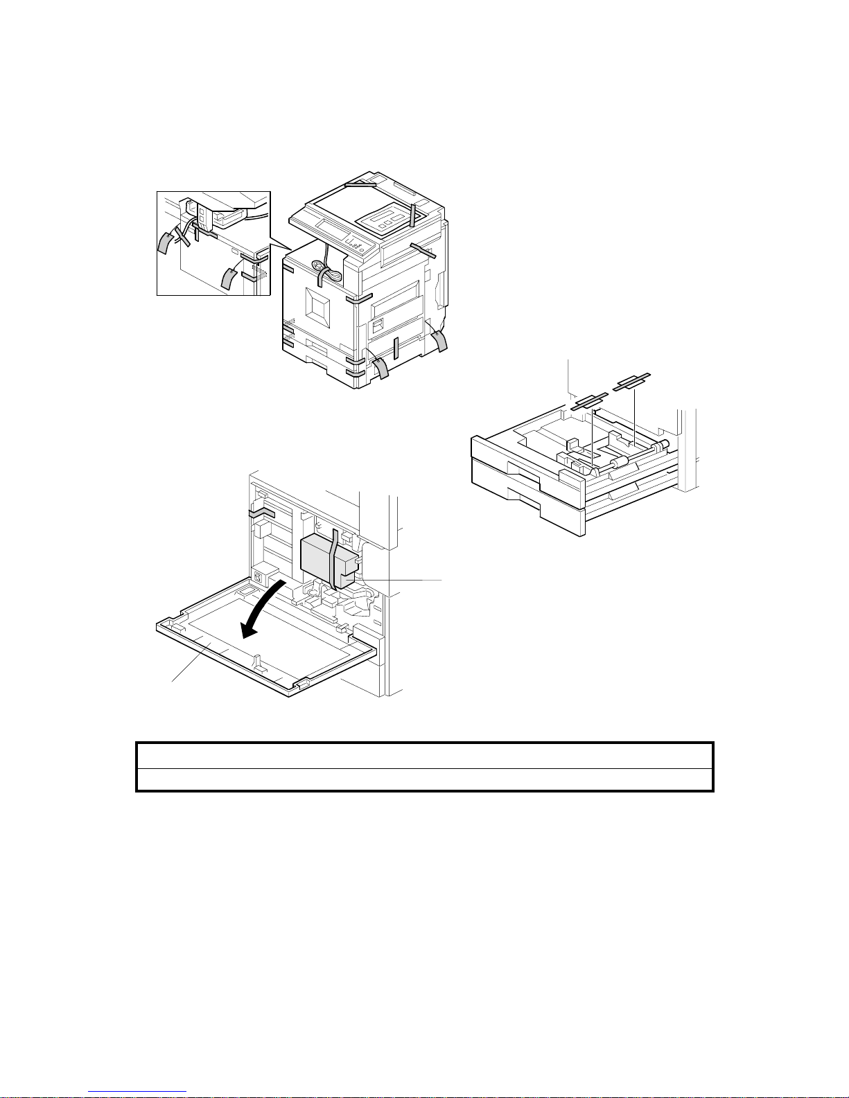
1. Remove the tapes.
2. Open the front cover [A] and remove the shipping retainer [B].
B051I101.WMF
B051I138.WMF
B051I125.WMF
[A]
[B]
Page 26
26 July 2002 COPIER (B051/B052)
1-7
Installation
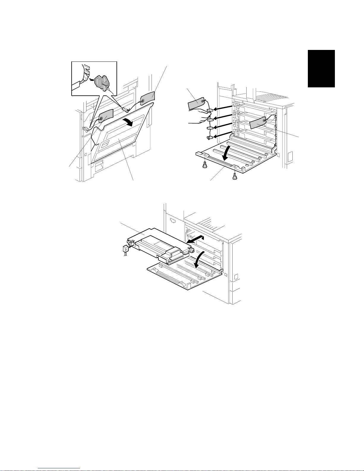
3. Open the right cover [A], and remove the red tags [B].
4. Open the left cover [C] (! x 2), and remove the red tags [D].
5. Pull out all development units [E] (" x 1 each).
B051I134.WMF
B051I124.WMF
B051I110.WMF
[C]
[D]
[D]
[A]
[B]
[B]
[E]
Page 27
COPIER (B051/B052) 26 July 2002
1-8
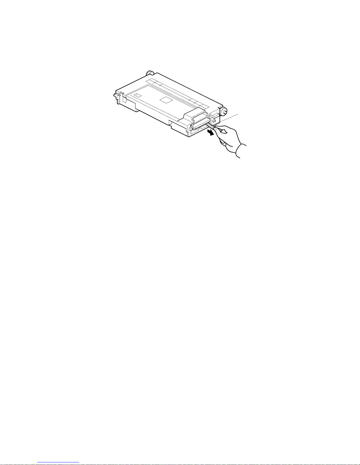
6. Peel off the toner cartridge seal [A].
7. Reinstall the toner cartridge in the development unit.
B051I133.WMF
[A]
Page 28
26 July 2002 COPIER (B051/B052)
1-9
Installation
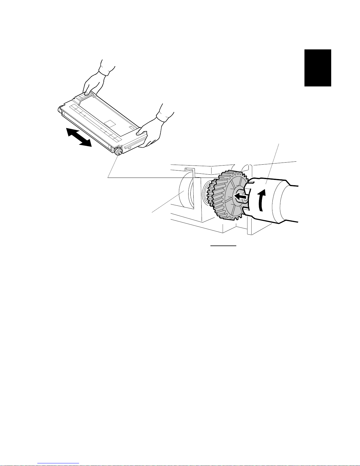
8. Keep the development unit level and shake the development unit about 10
times from side to side.
NOTE: 1) Do not touch the development roller or the development roller gear.
2) Use caution not to drop the cartridge or to damage it.
3) If the cartridge has not been shaken well, the machine takes a
longer time to initialize the development unit, or an error message or
SC350 is displayed. When either of them is displayed, turn the main
switch off and on.
9. Engage the special tool [A] (distributed with the machine) with the development
roller gear at the rear [B].
10. Turn the tool clockwise (approximately 5 times) until the toner covers the whole
area of the development roller [C].
NOTE: If the toner does not cover the whole area of the development roller,
redo step 8 to 10.
B051I315.WMF
B051I409.WMF
[A]
[C]
Rear view
[B]
Page 29
COPIER (B051/B052) 26 July 2002
1-10
11. Reinstall the development units, and close the left cover.
NOTE: A white line or band may appear on one end of the paper if a
development is incorrectly installed. To correct this, pull out the
development unit partially (about 30 mm) and slowly reinstall it.
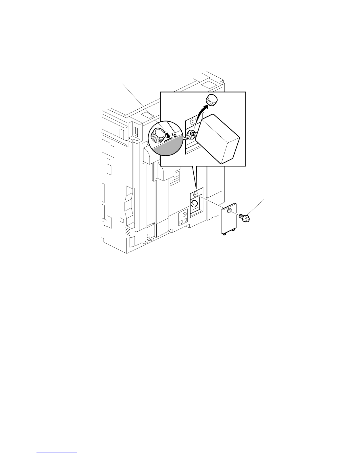
12. Remove the oil tank cover [A] (1 clip), and fill the oil tank to the maximum line.
NOTE: Do not fill the oil tank past the arrow [B].
B051I135.WMF
[A]
[B]
Page 30
26 July 2002 COPIER (B051/B052)
1-11
Installation
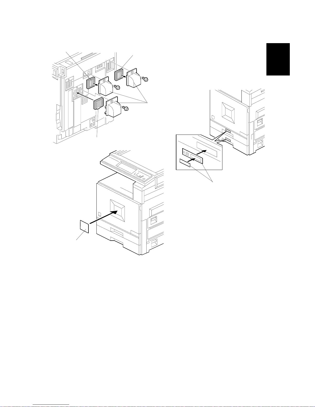
13. Install the filters [A] and ducts [B] as shown.
14. Attach the appropriate model name decal [C] to the front cover.
15. Pull the paper tray out, and adjust the side guides and end guide to match the
paper size.
NOTE: To move the side guides, first pull out the tray fully, then push down the
green lock at the rear inside the tray.
16. Attach the appropriate paper tray number decals [D] to the paper trays.
NOTE: Paper tray number decals are also used for the optional paper tray or
the optional LCT. Keep any remaining decals for use with these
optional units.
B051I137.WMF
B051I128.WMF
B051I131.WMF
[A]
[B]
[A]
[A]
[D]
[C]
Page 31

COPIER (B051/B052) 26 July 2002
1-12
17. If the optional bridge unit will not be installed: Swing the sensor feeler [A]
out.
18. Install the optional ARDF or the optional platen cover (see ARDF Installation or
Platen Cover Installation).
19. Plug in the machine and turn the main power switch on. The machine
automatically performs the initialization procedure. After this has finished, the
Start button LED turns green.
20. Make copies of image samples (text, photo, and text/photo modes).
21. Perform Automatic Color Calibration (ACC).
NOTE: Since this machine has been subject to color adjustment using
Automatic Color Calibration (ACC) at the factory, there is no need to
make automatic color calibration again if the customer is satisfied with
the image sample. If the customer is not satisfied, do the following.
1) Print the ACC test pattern (UP mode – Maintenance – ACC – Start).
2) Place the printout on the exposure glass.
3) Place 10 sheets of white paper on top of the test chart. Then, close
the ADF or platen cover.
4) Press “Start Scanning” on the LCD panel. The machine performs the
ACC.
22. Make sure that the sample image has been copied normally.
23. After installing the machine and all options, and making all test copies, initialize
the total counter (SP 7-825) if required by the service contract.
B051I129.WMF
[A]
Page 32

26 July 2002 PAPER TRAY UNIT (B456)
1-13
Installation
1.3 PAPER TRAY UNIT (B456)
1.3.1 ACCESSORY CHECK
Check the quantity and condition of the accessories against the following list.
No. Description Q’ty
1 Right Stand Bracket 1
2 Left Stand Bracket 1
3 Securing Bracket 2
4 Front Stand 1
5 Rear Stand 1
6 Screw - M4x10 4
7 Knob Screw 2
8 Stepped Screw 2
1.3.2 INSTALLATION PROCEDURE
!CAUTION
Unplug the machine power cord before starting the following procedure.
1. Remove the strips of tape.
B456I001.WMF
B456I002.WMF
1
2
3
4
5
6 7 8
Page 33

PAPER TRAY UNIT (B456) 26 July 2002
1-14
2. Remove the paper trays [A] from the paper tray unit and remove the shipping
retainers.
3. Install the front stand [B] (! x 2).
4. Install the rear stand [C].
5. Attach two stand brackets [D] (! x 1 each).
B456I103.WMF
B456I104.WMF
[A]
[B]
[D]
[C]
[D]
Page 34

26 July 2002 PAPER TRAY UNIT (B456)
1-15
Installation
6. Set the copier [A] on the paper tray unit [B].
7. Remove the paper trays [C] from the copier and secure the paper tray unit
(! x 2).
8. Attach a securing bracket [D] to each side of the paper tray unit (! x 1 each).
B456I105.WMF
B456I102.WMF
B456I106.WMF
[A]
[B]
[C]
[D]
[D]
Page 35

PAPER TRAY UNIT (B456) 26 July 2002
1-16
9. Reinstall the paper trays and attach the appropriate paper tray number decal
[A] to the paper tray.
NOTE: The paper tray number decal is in the accessory box for the main
copier.
10. Load paper into the paper trays.
11. Turn on the main switch.
12. Check the machine’s operation and copy quality.
B456I004.WMF
[A]
Page 36

26 July 2002 LCT (B457)
1-17
Installation
1.4 LCT (B457)
1.4.1 ACCESSORY CHECK
Check the quantity and condition of the accessories against the following list.
No. Description Q’ty
1 Right Stand Bracket 1
2 Left Stand Bracket 1
3 Securing Bracket 2
4 Front Stand 1
5 Rear Stand 1
6 Screw - M4x10 4
7 Knob Screw 2
8 Stepped Screw 2
1.4.2 INSTALLATION PROCEDURE
!CAUTION
Unplug the machine power cord before starting the following procedure.
1. Remove the strips of tape.
B457I151.WMF
B457I001.WMF
1
2 3
4
5
6 7 8
Page 37

LCT (B457) 26 July 2002
1-18
2. While pressing the stopper [A] attached to the guide rail, pull out the large
capacity tray [B].
3. Install the front stand [C] (! x 2).
4. Install the rear stand [D].
5. Attach two stand brackets [E] (! x 1 each).
B457I003.WMF
B457I104.WMF
[A]
[B]
[E]
[D]
[E]
[C]
Page 38

26 July 2002 LCT (B457)
1-19
Installation
6. Set the copier [A] on the LCT [B].
7. Remove the paper trays [C] from the copier and secure the LCT (! x 2).
8. Attach a securing bracket [D] to each side of the LCT (! x 1 each).
B457I006.WMF
B457I002.WMF
B457I156.WMF
[A]
[B]
[C]
[D]
[D]
Page 39

LCT (B457) 26 July 2002
1-20
9. Reinstall the paper trays and attach the appropriate paper tray number decal
[A] to the LCT.
NOTE: The paper tray number decal is in the accessory box for the main
copier.
10. Load paper into the LCT.
11. Turn on the main switch.
12. Check the machine’s operation and copy quality.
B457I005.WMF
[A]
Page 40

26 July 2002 AUTO REVERSE DOCUMENT FEEDER (B386)
1-21
Installation
1.5 AUTO REVERSE DOCUMENT FEEDER (B386)
1.5.1 ACCESSORY CHECK
Check the quantity and condition of the accessories against the following list.
No. Description Q’ty
1 Scale Guide 1
2 DF Exposure Glass 1
3 Stud Screw 2
4 Knob Screw 2
5 Original Size Decal 2
6 Screwdriver Tool 1
1.5.2 INSTALLATION PROCEDURE
!CAUTION
Unplug the copier power cord before starting the following procedure.
1. Remove the strips of tape.
B386I500.WMF
B386I101.WMF
1
2
4
5
3
6
Page 41

AUTO REVERSE DOCUMENT FEEDER (B386) 26 July 2002
1-22
2. Remove the left scale [A] (! x 2).
3. Peel off the backing [B] of the double-sided tape attached to the glass holder.
4. Place the DF exposure glass [C] on the glass holder.
NOTE: When installin g the DF exposure glass, make sure that the white point
[D] is on the lower front side of the glass, as shown.
5. Peel off the backing [E] of the double-sided tape attached to the rear side of the
scale guide [F], then install the scale guide [F] (! x 2 removed i n step 2).
6. Install two stud screws [G].
7. Mount the DF on the copier, then slide the DF to the front as shown.
8. Secure the DF unit with two screws [H].
9. Connect the cable [I] to the copier.
B386I107.WMF
B386I108.WMF
[H]
[I]
[H]
[A]
[B]
[C]
[D]
[E]
[F]
[G]
[G]
Page 42

26 July 2002 AUTO REVERSE DOCUMENT FEEDER (B386)
1-23
Installation
10. Peel off the platen sheet [A] and place it on the exposure glass.
11. Line up the rear left corner of the platen sheet flush against corner [B] on the
exposure glass.
12. Close the ARDF.
13. Attach the appropriate scale decal [C] as shown.
14. Turn the main power switch on. Then check if the document feeder works
properly.
15. Make a full size copy. Check that the registrations (side-to-side and leading
edge) and image skew are correct. If they are not, adjust the registrations and
image skew (refer to Replacements and Adjustments – Copy Adjustments).
B386I110.WMF
B386I111.WMF
B386I501.WMF
[A]
[B]
[C]
Page 43

INTERCHANGE UNIT (B481) 26 July 2002
1-24
1.6 INTERCHANGE UNIT (B481)
1.6.1 ACCESSORY CHECK
Check the quantity and condition of the components against the following list.
No. Description Q’ty
1 Interchange Unit 1
B481I101.WMF
Page 44

26 July 2002 INTERCHANGE UNIT (B481)
1-25
Installation
1.6.2 INSTALLATION PROCEDURE
!CAUTION
Unplug the copier power cord before starting the following procedure.
1. Remove all tapes.
2. Open the right cover [A] of the copier.
3. Open cover [B] and remove it.
NOTE: Pull down in the direction of the arrow. Do not pull directly outwards.
4. Remove the connector cover [C] (! x 1)
5. Open the cover [D] of the interchange unit.
6. Install the interchange unit [E] (" x 1).
NOTE: Take care not to pinch the harness at the front side (near [E] in the
drawing). This harness is not used in this procedure, but is used when
installing another option.
7. Secure the interchange unit with the knob screws [F].
8. Reinstall the connector cover [G] which was removed in step 4.
B481I102.WMF
B481I103.WMF
[A]
[B]
[C]
[D]
[E]
[F]
[F]
[G]
Page 45

1-BIN TRAY UNIT (B480) 26 July 2002
1-26
1.7 1-BIN TRAY UNIT (B480)
1.7.1 ACCESORY CHECK
Check the quantity and condition of the components against the following list.
No. Description Q’ty
1 1-Bin Tray Unit 1
2 Tray 1
3 Sub-Tray 1
4 Tray Guide 1
5 Shield Mylar 1
6 Sub Paper Guide 1
7 Paper Guide 1
8 Tapping Screw M3x8 2
B480I101.WMF
1
2
3
4
5
6
7
8
Page 46

26 July 2002 1-BIN TRAY UNIT (B480)
1-27
Installation
1.7.2 INSTALLATION PROCEDURE
!CAUTION
Unplug the copier power cord before starting the following procedure.
NOTE: Before installing this 1-bin tray unit, the optional interchange unit
(B416) must be installed.
1. Remove all tapes.
2. If the optional bridge unit has been installed, open the right jam removal cover
[A] of the bridge unit.
If the optional bridge unit is not installed, skip this step.
B480I107.WMF
[A]
Page 47

1-BIN TRAY UNIT (B480) 26 July 2002
1-28
3. Peel off the backing of the double-sided tape attached to the shield mylar [A].
Then attach the shield mylar to the 1-bin unit.
4. If the front right cover [B] is installed, remove it (! x 1).
5. Remove the cover [C].
6. Disconnect the connector [D] and remove the LED board [E].
7. Install the 1-bin tray unit [F] (! x 1).
B480I103.WMF
B480I102.WMF
B480I108.WMF
[B]
[C]
[F]
[D]
[E]
[A]
Page 48

26 July 2002 1-BIN TRAY UNIT (B480)
1-29
Installation
8. Install the LED board [A] on the front right cover (! x 1).
9. Reinstall the front right cover [B] (" x 2, ! x 1).
10. Peel off the backing of the double-sided tape attached to the paper guide [C].
Then attach the paper guide to the underside of the scanner unit as shown.
11. Peel off the backing of the double-sided tape attached to the sub paper guide
[D]. Then attach the sub paper guide to the underside of the scanner unit as
shown.
12. Install the tray guide [E].
13. Install the tray [F].
14. Install the sub-tray [G].
15. Turn on the main power switch and check the 1-bin tray unit operation.
B480I106.WMF
B480I104.WMF
B480I109.WMF
[A]
[B]
[C]
[D]
[E]
[F]
[G]
Page 49

SHIFT TRAY 26 July 2002
1-30
1.8 SHIFT TRAY
1.8.1 COMPONENT CHECK
Check the quantity and condition of the components against the following list.
No. Description Q’ty
1 Shift Tray Unit 1
2 Paper Guide - Large 1
3 Paper Guide - Small 2
4 Stepped Screw 1
1.8.2 INSTALLATION PROCEDURE
!CAUTION
Unplug the copier power cord before starting the following procedure.
1. Remove all tapes (see the diagram at the top of the page).
2. Remove the covers [A] (! x 1).
3. Replace screw [B] with a stepped screw [C].
4. Install the large paper guide [D] and two small paper guides [E].
B510I101.WMF
B510I102.WMF
1
2
3
4
[A]
[D]
[E]
[E]
[B]
[C]
Page 50

26 July 2002 SHIFT TRAY
1-31
Installation
5. Remove the rear cover [A] (! x 2).
6. Pass the harnesses [B] through the opening [C], and install the shift tray unit
[D], as shown.
NOTE: 1) Set the shift tray on the stepped screw.
2) The shift tray must be installed under the paper guides [E] installed
in step 4.
B510I103.WMF
B510I110.WMF
[C]
[B]
[A]
[D]
[E]
Page 51

SHIFT TRAY 26 July 2002
1-32
7. Connect the harnesses [A], as shown.
8. Turn on the main power switch.
9. Check the shift tray operation.
B510I104.WMF
[A]
Page 52

26 July 2002 BY-PASS FEED UNIT (B490)
1-33
Installation
1.9 BY-PASS FEED UNIT (B490)
1.9.1 ACCESSORY CHECK
Check the quantity and condition of the components against the following list.
No. Description Q’ty
1 By-pass Tray Unit 1
2 Tapping Screw 3
1.9.2 INSTALLATION PROCEDURE
!CAUTION
Unplug the copier power cord before starting the following procedure.
1. Remove all tapes (see the diagram at the top of the page).
2. Remove the entrance cover [A] (!x 2).
B490I001.WMF
B490I113.WMF
1
2
[A]
Page 53

BY-PASS FEED UNIT (B490) 26 July 2002
1-34
3. Install the by-pass tray unit [A] (! x 3, " x 1).
4. Turn the main power switch on and check the by-pass tray function.
5. Make a copy from the by-pass tray. Then check the registration.
B490I114.WMF
[A]
Page 54

26 July 2002 DUPLEX UNIT (B509)
1-35
Installation
1.10 DUPLEX UNIT (B509)
1.10.1 ACCESSORY CHECK
Check the quantity and condition of the accessories against the following list.
No. Description Q’ty
1 Duplex Unit 1
2 Upper Bracket 1
3 Rear Holder Bracket 1
4 Front Holder Bracket 1
5 Clip 2
6 Tapping Screw - M4x6 3
7 Tapping Screw - M3x6 1
B509I101.WMF
1
2
3
4
5
6
7
Page 55

DUPLEX UNIT (B509) 26 July 2002
1-36
1.10.2 INSTALLATION PROCEDURE
!CAUTION
Unplug the copier power cord before starting the following procedure.
NOTE: Before installing the duplex unit, the optional interchange unit (B481)
must be installed.
1. Remove all tapes (see the previous page).
2. Remove five covers [A] (! x 1).
3. Install three brackets [B] (! x 1 each - M4x6).
B509I102.WMF
B509I103.WMF
[A]
[A]
[A]
[B]
[B]
Page 56

26 July 2002 DUPLEX UNIT (B509)
1-37
Installation
4. Set the duplex unit [A] on the brackets [B] (1 clip).
5. Attach the link [C] to the shaft [D] and secure it with the clip.
6. Remove the connector cover [E] (! x 1).
7. Connect the cable [F] and secure the grounding wire [G] (! x 1).
8. Install the connector cover.
9. Turn on the main power switch and check the duplex unit function.
B509I104.WMF
B509I105.WMF
[A]
[B]
[C]
[D]
[B]
[F]
[E]
[G]
Page 57

BRIDGE UNIT (B482) 26 July 2002
1-38
1.11 BRIDGE UNIT (B482)
1.11.1 ACCESSORY CHECK
Check the quantity and condition of the accessories against the following list.
No. Description Q’ty
1 Bridge Unit 1
2 Rear Joint Bracket 1
3 Front Joint Bracket 1
4 Knob Screw 1
5 Screw - M3x6 1
6 Screw - M4x14 4
1.11.2 INSTALLATION PROCEDURE
!CAUTION
Unplug the copier power cord before starting the following procedure.
1. Remove all tapes.
2. If the sensor feeler [A] is out, fold it away into the machine.
B482I101.WMF
B482I500.WMF
1
2
3
4
5
6
[A]
Page 58

26 July 2002 BRIDGE UNIT (B482)
1-39
Installation
3. Remove the front right cover [A] (! x 1).
4. Remove two covers [B] (! x 1 each).
5. Remove the rear cover [C] (! x 2).
6. Pass the harnesses [D] through the opening [E], and install the bridge unit [F]
(! x 2).
7. Reinstall the front right cover.
B482I102.WMF
B482I103.WMF
B482I104.WMF
[A]
[B]
[B]
[D]
[E]
[F]
[C]
Page 59

BRIDGE UNIT (B482) 26 July 2002
1-40
8. Connect the harnesses [A], as shown.
9. Reinstall the rear cover.
10. When the 1,000-sheet finisher (Machine code: B408) will be installed,
attach the front joint bracket [B] and rear joint bracket [C] (! x 2 each).
11. Install the optional finisher (refer to the finisher installation procedure).
B482I105.WMF
B482I106.WMF
[A]
[B]
[C]
Page 60

26 July 2002 1000-SHEET FINISHER (B408)
1-41
Installation
1.12 1000-SHEET FINISHER (B408)
1.12.1 ACCESSORY CHECK
Check the quantity and condition of the accessories against the following list.
No. Description Q’ty
For
B022/B027/B031
For
B051/B052
1 Front Joint Bracket 1 O X
2 Rear Joint Bracket 1 O X
3 Grounding Plate 1 O X
4 Copy Tray 1 O O
5 Staple Position Decal 1 O O
6 Screw - M4x17 3 O X
7 Knob Screw - M4x10 1 O O
8 Screw - M3x8 1 O X
9 Knob Screw - M3x8 1 O O
O = Necessary, X = Not necessary
B408I101.WMF
1
2
3
4
5
8 9
6 7
Page 61

1000-SHEET FINISHER (B408) 26 July 2002
1-42
1.12.2 INSTALLATION PROCEDURE
!CAUTION
Unplug the main machine power cord before starting the following
procedure.
NOTE: The following options must be installed before installing this finisher.
- Bridge Unit (B482)
- Paper Tray Unit (B456) or LCT (B457)
Also, the optional adjustment table (B488) is required.
1. Unpack the finisher and remove the tapes.
B408I102.WMF
B408I103.WMF
[A]
Page 62

26 July 2002 1000-SHEET FINISHER (B408)
1-43
Installation
2. Unpack the adjustment table (B488).
3. Set the finisher [A] on the adjustment table [B] and secure the finisher (! x 1).
4. Install the grounding plate [C], which is in the accessory box for the adjustment
table (! x 2).
5. Open the front door [D], then pull the locking lever [E].
6. Align the finisher on the joint brackets, and lock it in place by pushing the
locking lever.
7. Secure the locking lever (1 knob screw - M3x8) and close the front door.
8. Install the copy tray [F] (1 knob screw - M4x10).
9. Connect the finisher cable [G] to the main machine.
B408I152.WMF
B408I114.WMF
[A]
[B]
[C]
[D]
[E]
[F]
[G]
Page 63

1000-SHEET FINISHER (B408) 26 July 2002
1-44
10. Attach the staple position decal [A] to the ARDF as shown.
11. Turn on the main power switch and check the finisher operation.
B408I501.WMF
[A]
Page 64

26 July 2002 500-SHEET FINISHER (B458)
1-45
Installation
1.13 500-SHEET FINISHER (B458)
1.13.1 ACCESSORY CHECK
Check the quantity and condition of the accessories against the following list.
No. Description Q’ty
1 Unit Holder 1
2 Entrance Guide 1
3 Shift Tray 1
4 Snap Ring 2
5 Knob Screw 2
B458I102.WMF
1
2
3
4 5
Page 65

500-SHEET FINISHER (B458) 26 July 2002
1-46
1.13.2 INSTALLATION PROCEDURE
!CAUTION
Unplug the main machine power cord before starting the following
procedure.
NOTE: Before installing the 500-sheet finisher, the optional bridge unit
(B482) must be installed.
1. Unpack the finisher and remove the tapes.
2. Install the entrance guide [A].
3. Remove the holder cover [B]. Then install the unit holder [C] (2 screws).
4. Re-install the holder cover [B].
B458I101.WMF
B458I103.WMF
[A]
[C]
[B]
Page 66

26 July 2002 500-SHEET FINISHER (B458)
1-47
Installation
5. Install the 500-sheet finisher [A] (" x 1).
6. Install the output tray [B] as shown (2 snap rings).
7. Turn on the main power switch and check the finisher operation.
B458I105.WMF
B458I104.WMF
[B]
[A]
Page 67

PLATEN COVER INSTALLATION 26 July 2002
1-48
1.14 PLATEN COVER INSTALLATION
1. Install the platen cover [A] (! x 2).
2. Peel off the platen sheet [B] and place it on the exposure glass.
3. Line up the rear left corner of the platen sheet flush against corner [C] on the
exposure glass.
4. Gently close the platen cover.
B051I520.WMF
B051I408.WMF
[A]
[B]
[C]
Page 68

26 July 2002 MEMORY
1-49
Installation
1.15 MEMORY
!CAUTION
Unplug the main machine power cord before starting the following
procedure.
1. Remove the rear cover [A] (! x 2).
2. Remove the cooling fan [B] (! x 2).
3. Remove the PCB fan [C] (! x3, " x 1).
4. Remove the BICU cover [D] (! x 16).
5. Remove the HDD connector cover [E] (! x 4).
6. Disconnect two HDD harnesses [F].
7. Remove the controller board cover [G] (! x 7).
B051I554.WMF
B051I504.WMF
B051I505.WMF
[D]
[E]
[F]
[G]
[A]
[B]
[C]
Page 69

MEMORY 26 July 2002
1-50
8. Install the memory DIMM [A] on the controller board.
9. Replace the controller board cover and rear cover.
B051I308.WMF
[A]
Page 70

26 July 2002 KEY COUNTER INSTALLATION
1-51
Installation
1.16 KEY COUNTER INSTALLATION
!CAUTION
Unplug the main machine power cord before starting the following
procedure.
1. Remove the rear cover [A] (! x 2).
2. Remove the upper right cover [B] (! x 1).
3. Remove the cap [C].
4. Install the bracket [D] (! x 2).
5. Connect the cable [E] to the BICU board and route it as shown.
B051I554.WMF
B051I119.WMF
B051I120.WMF
[A]
[B]
[C]
[D]
[E]
Page 71

KEY COUNTER INSTALLATION 26 July 2002
1-52
6. Hold the key counter plate nuts [A] on the inside of the key counter bracket [B]
and insert the key counter holder [C].
7. Secure the key counter holder to the bracket (! x 2).
8. Install the key counter cover [D] (! x 2).
9. Install the stepped screw [E].
1. Connect the cable [F].
10. Hook the key counter holder assembly [G] onto the stepped screw and secure
it (! x 1).
11. The restricted access control for the key counter is enabled by the Copier UP
mode.
B051I515.WMF
B051I121.WMF
[A]
[B]
[C]
[D]
[E]
[F]
[G]
Page 72

26 July 2002 ANTI-CONDENSATION HEATER
1-53
Installation
1.17 ANTI-CONDENSATION HEATER
!CAUTION
Unplug the main machine power cord before starting the following
procedure.
1. Remove the rear scale [A] (! x 3), left scale [B] (! x 2), and exposure glass
[C].
NOTE: When installing the exposure glass, make sure th at the mark [D] is
positioned at the rear left corner, as shown.
2. Install the anti-condensation heater [E] (! x 2, " x 1).
3. Reinstall the exposure glass and the scales.
B051I151.WMF
B051I139.WMF
[A]
[B]
[C]
[D]
[E]
Page 73

TRAY HEATER 26 July 2002
1-54
1.18 TRAY HEATER
!CAUTION
Unplug the main machine power cord before starting the following
procedure.
1. Remove the rear cover [A] (! x 2).
2. Slide out the 1st and 2nd paper trays.
3. Pass the connector [B] through the opening [C].
4. Install the tray heater assembly [D] (! x 1).
5. Connect the heater cable to the ac cable [E].
6. Reassemble the machine.
B051I554.WMF
B051I140.WMF
B051I141.WMF
[A]
[B]
[C]
[D]
[B]
[E]
Page 74

26 July 2002 TRAY HEATER (OPTIONAL PAPER TRAY UNIT)
1-55
Installation
1.19 TRAY HEATER (OPTIONAL PAPER TRAY UNIT)
!CAUTION
Unplug the main machine power cord before starting the following
procedure.
1. Remove the rear cover for the main machine [A] (! x 2).
2. Remove the joint brackets [B] (! x 1 each).
3. Remove the rear cover for the optional paper tray unit [C] (! x 2).
4. Slide out the paper trays from the optional paper tray unit.
5. Pass the connector [D] through the opening [E].
6. Install the tray heater [F] (! x 1).
B456I104.WMF
B456I502.WMF
B456I201.WMF
[D]
[E]
[F]
[A]
[C]
[B]
[B]
Page 75

TRAY HEATER (OPTIONAL PAPER TRAY UNIT) 26 July 2002
1-56
7. Remove the oil bottle [A] and the oil bottle bracket [B] (! x 3).
8. Install the clamp [C].
9. Connect the cable [D] to the heater cable [E] and the PSU [F]. Then clamp the
cable.
10. Reinstall the rear covers.
B456I202.WMF
[A]
[B]
[C]
[D]
[E]
[F]
Page 76

26 July 2002 TRAY HEATER (OPTIONAL LCT)
1-57
Installation
1.20 TR AY HEATER (OPTIONAL LCT)
!CAUTION
Unplug the main machine power cord before starting the following
procedure.
1. Remove the rear cover for the main machine [A] (! x 2).
2. Remove the joint brackets [B] (! x 1 each).
3. Remove the rear cover for the optional LCT [C] (! x 2).
4. Slide out the paper tray [D] from the optional LCT.
5. Push stopper [E] on the right slide rail and remove the paper tray.
B457I554.WMF
B457I502.WMF
B457I501.WMF
[C]
[B]
[B]
[A]
[D]
[E]
Page 77

TRAY HEATER (OPTIONAL LCT) 26 July 2002
1-58
6. Pass the connector [A] through the opening [B].
7. Install the tray heater [C] (! x 1).
8. Remove the oil bottle [D] and the oil bottle bracket [E] (! x 3).
9. Install the clamp [F].
10. Connect the cable [G] to the heater cable [H] and the PSU [I]. Then clamp the
cable.
11. Reinstall the rear covers.
B457I251.WMF
B457I201.WMF
[A] [B]
[C]
[D]
[E]
[F]
[G]
[H]
[I]
Page 78

26 July 2002 MAIN UNIT
2-1
Preventive
Maintenance
2. PREVENTIVE MAINTENANCE
2.1 MAIN UNIT
2.1.1 OVERVIEW
B051P112.WMF
Oil supply unit
PCU
Fusing subunit
Charge corona unit
Page 79

MAIN UNIT 26 July 2002
2-2
2.1.2 PM TABLE
After replacing a part, reset the PM counter for that part (SP 7-804).
Abbreviations: Clean, Inspect, Oil replenishment, Replace, Emergency Maintenance
Optical System
Prints Developments
70K 80K 120K 70K 120K 240K
EM Remarks
White plate C Optical cloth
1st mirror C Optical cloth
2nd mirror C Optical cloth
3rd mirror C Optical cloth
Front/rear rails C Damp/dry cloth
Exposure glass C C Glass cleaner
Dust shield glass
(laser optics unit)
C C
Optical cloth and dry
cloth
APS sensors C Dry cloth
Around the PCU
Prints Developments
70K 80K 120K 50K 120K 240K
EM Remarks
Charge corona unit
R
Replace as whole units
or individual parts
(listed below).
PCU R
T/B waste toner bottle R C Empty the bottle
ID sensor C Blower brush
O/B waste toner bottle C R C Empty the bottle
.Components Parts of the Charge Corona Unit
Prints Developments
70K 80K 120K 50K 120K 240K
EM Remarks
Charge Corona Wire R
Charge Corona Grid R
Charge Corona Cleaner R
Development Unit
Prints Developments
70K 80K 120K 60K 120K 240K
EM Remarks
Development unit-C R
Development unit-M R
Development unit-Y R
Development unit-K R
Refer to the PM
counter for each unit
(Not reclaimed at the
reclamation center)
Page 80

26 July 2002 MAIN UNIT
2-3
Preventive
Maintenance
Paper feed System
Prints Developments
70K 80K 120K 75K 120K 240K
EM Remarks
Idle roller (registration) C Damp/dry cloth
Registration sensor C Damp/dry cloth
Transport guide C Damp/dry cloth
Feed roller (main unit) R
Vertical transport roller C Damp/dry cloth
Friction pad (main unit) R
Fusing Unit
Prints Developments
60K 80K 120K 75K 120K 240K
EM Remarks
Fusing subunit R
Oil supply unit
R
Replace as whole units
or individual parts
(listed below).
Thermistor I
Fusing oil O
.Components Parts of the Fusing Sub Unit and Oil Supply Unit
Prints Developments
60K 80K 120K 75K 120K 240K
EM Remarks
Oil supply pad
R
Sponge roller
R
Fusing cleaning roller
R
Rear oil absorber R
Front oil absorber
R
Front oil tank absorber
R
Long oil tank absorber
R
Rear oil tank absorber
R
Fusing cover absorber
R
Oil supply roller
R
Oiling roller
R
Pressure cleaning roller
R
Fusing belt unit
R
Pressure roller
R
Pressure roller strippers
R
Idle gear – 28Z/35Z
R
Gear – 47Z
R
Front spring plate
R
Rear spring plate
R
Page 81

MAIN UNIT 26 July 2002
2-4
Filters
Prints Developments
70K 80K 120K 75K 120K 240K
EM Remarks
Exhaust filters R
Ozone filter R
By-pass Tray Unit
Prints Developments
70K 80K 120K 75K 120K 240K
EM Remarks
Feed roller R
Pickup roller R
Separation roller R
Friction pad C Damp cloth
Page 82

26 July 2002 OPTIONAL UNIT PM TABLE
2-5
Preventive
Maintenance
2.2 OPTIONAL UNIT PM TABLE
Abbreviations: Clean, Inspect, Oil replenishment, Replace, Emergency Maintenance
Duplex Unit
Prints Developments
70K 80K 120K 75K 120K 240K
EM Remarks
Idle roller (inverter) C Damp/dry cloth
Idle roller
(vertical transport)
C
Damp/dry cloth
Auto-reverse Document Feeder
Prints Developments
70K 80K 120K 75K 120K 240K
EM Remarks
Pickup roller R
Feed belt R
Separation roller R
Stamp I
ADF exposure glass C C Damp/dry cloth
Platen cover C C Damp/dry cloth
Paper Tray Unit
Prints Developments
70K 80K 120K 75K 120K 240K
EM Remarks
Pickup roller R
Feed roller R
Separation roller R
Large Capacity Tray
Prints Developments
70K 80K 120K 75K 120K 240K
EM Remarks
Pickup roller R
Feed roller R
Separation roller R
Page 83

26 July 2002 SPECIAL TOOLS
3-1
Replacement
Adjustment
3. REPLACEMENT A ND ADJUSTMENT
!CAUTION
Turn off the main power switch and unplug the machine before beginning
any of the procedures in this section.
NOTE: This manual uses the following symbols.
☛ : See or Refer to ! : Screws " : Connector # : Clip ring
$ : E-ring
3.1 SPECIAL TOOLS
Part Number Description Q’ty
A0069104 Scanner Positioning Pin (4 pcs/set) 1
N8036701 Flash Memory Card - 4MB 1
A0929503 C4 Color Test Chart (3 pcs/set) 1
C4019503 20X Magnification Scope 1
3.2 FILTERS
1. Filter covers [B, D, and E]
2. Exhaust filters [A, C, G, and I]
3. Filter holder [F]
4. Ozone filter [H]
B051R819.WMF
[A]
[B]
[C]
[D]
[E]
[F]
[G] [H]
[I]
Page 84

SCANNER UNIT 26 July 2002
3-2
3.3 SCANNER UNIT
3.3.1 EXPOSURE GLASS
1. Rear scale [A] (! x 3)
2. Left scale [B] (! x 2)
NOTE: After replacing the left scale,
adjust the scanner white level
(☛ 3.14).
3. Exposure glass [C]
NOTE: When rea ssembling, position the
glass marker [D] at the rear-left
corner.
3.3.2 APS SENSORS
1. Exposure glass (☛ 3.3.1)
2. Original length sensor 1 [A]
(! x 1, " x 1)
3. Original length sensor 2 [B]
(! x 1, " x 1)
4. Original width sensor [C]
(! x 1, " x1)
B051R001.WMF
B051R003.WMF
[A]
[B]
[C]
[A]
[C]
[B]
[D]
Page 85

26 July 2002 SCANNER UNIT
3-3
Replacement
Adjustment
3.3.3 LENS BLOCK ASSEMBLY
1. Exposure glass (☛ 3.3.1)
2. Rear cover (☛ 3.4.2)
3. Scanner right cover [A] (! x 1)
4. Inner cover [B] (! x 4)
5. Lens block assembly [C]
(! x 4, " x 4)
NOTE: Do not remove the paint-
locked screws.
6. After reassembling, input the data
in accordance with the data sheet
included in the spare SBU unit (☛
SP4-540).
Refer to the diagram on the next
page.
• Row No. 1: Numbers 1 to 6 –
please ignore
• Row No. 2: Numbers 7 to 10 –
please store in the following SP
modes
7: SP 4-540-001
8: SP 4-540-002
9: SP 4-540-003
10: SP 4-540-004
• Row No. 3: Numbers 11 to 14 – please store in the following SP modes
11: SP 4-540-021
12: SP 4-540-022
13: SP 4-540-023
14: SP 4-540-024
• Before inputting the number, check whether it is + or – (look at the data
sheet), then input a +ve or –ve number accordingly.
7. Check the registrations (☛ SP4-010/011 Chapter 3, Copy adjustments)
NOTE: After replacing the left scale , adjust the scanner white level (☛ 3.14).
B051R004.WMF
B051R005.WMF
[B]
[C]
[A]
Page 86

SCANNER UNIT 26 July 2002
3-4
B051S999.PCX
Page 87

26 July 2002 SCANNER UNIT
3-5
Replacement
Adjustment
3.3.4 EXPOSURE LAMP STABILIZER
1. Lens block assembly (☛ 3.3.3)
2. Exposure lamp stabilizer [A]
(! x 2, " x 2)
3.3.5 SCANNER LAMP
1. Exposure glass (☛ 3.3.1)
2. Rear cover (☛ 3.4.2)
3. Operation panel [A]
(! x 5, " x 1)
4. Scanner right cover [B] (! x 1)
5. Scanner left cover [C] (! x 1)
6. Scanner rear cover [D] (! x 1)
7. Left frame [E] (! x 2)
8. Front frame [F] (! x 5)
B051R006.WMF
B051R002.WMF
B051R009.WMF
[A]
[B]
[C]
[F]
[E]
[A]
[D]
Page 88

SCANNER UNIT 26 July 2002
3-6
9. Lamp guard [A] (! x 2)
10. Pulley [B]
NOTE: Use caution not to
bend the pulley guides.
11. Push down the part [C], then
slide out the scanner lamp.
12. Slide out the scanner lamp [D]
and unhook it from the clamps
[E].
NOTE: After replacing the
scanner lamp, adjust
the scanner white level
(☛ 3.14).
Reassembling
1. Take up the cable slack.
NOTE: Make sure the cable is not dangling and the wires are not crossed.
2. Adjust the cable clamp position [F] if necessary.
NOTE: Do not open the clamp.
B051R012.WMF
[A]
[B]
[D]
[E]
[F]
[C]
Page 89

26 July 2002 SCANNER UNIT
3-7
Replacement
Adjustment
3.3.6 SC ANNER I/ O BOARD
1. Scanner right cover and scanner rear
cover (☛ 3.3.5)
2. Scanner I/O board [A] (! x 6, " x 7)
3.3.7 SCANNER MOTOR
1. Scanner I/O board (☛ 3.3.6)
2. Scanner motor [A] (! x 2, Spring x 1)
3. Timing belt [B]
3.3.8 FRONT SCANNER WIRE
1. Front frame (☛ 3.3.5)
2. To make reassembly easy, slide the
first scanner to the right
(☛ Reassembling the Front Scanner
Wire).
3. Front scanner wire clamp [A]
4. Front scanner wire bracket [B]
(! x 1)
5. Front scanner wire and scanner drive
pulley [C] (! x 1)
B051R007.WMF
B051R008.WMF
B051R943.WMF
[A]
[A]
[B]
[A]
[B]
[C]
Page 90

SCANNER UNIT 26 July 2002
3-8
Reassembling the Front Scanner Wire
1. Pass the end with the ball [A]
through the left square hole
from the front.
2. Position the center ball [B] in
the middle of the notch, as
shown by the arrow.
3. Pass the ball end [A] through
the notch on the right.
4. Wind the end with the ring [C]
clockwise three times; wind the
ball end [A] counterclockwise
five times.
NOTE: The two red marks [D]
should meet when you
have done this.
5. Stick the wire to the pulley with
tape, so you can easily handle
the pulley and wire during
installation.
6. Install the drive pulley on the
shaft [E].
NOTE: Do not screw the pulley
onto the shaft yet.
7. Insert the ball end into the slit [F],
with the end going via the rear
track of the left pulley [G] and
the rear track of the movable
pulley [H].
B051R944.WMF
B051R945.WMF
[B]
[A]
[C]
[D]
[E]
[F]
[G]
[H]
Page 91

26 July 2002 SCANNER UNIT
3-9
Replacement
Adjustment
8. Hook the ring end onto the front
scanner wire bracket [I], with the
end going via the front track of
the right pulley [J] and the front
track of the movable pulley [K].
NOTE: Do not screw the
scanner wire bracket in
place yet.
9. Remove the tape from the drive
pulley.
10. Insert a scanner positioning pin
[L] through the 2nd carriage hole
[M] and the left holes [N] in the
front rail. Insert another scanner
positioning pin [O] through the
1st carriage hole [P] and the
right holes in the front rail [Q].
11. Insert two more scanner
positioning pins through the
holes in the rear rail.
12. Screw the drive pulley to the
shaft [R].
13. Screw the scanner wire bracket
to the front rail [S].
14. Install the scanner wire clamp [T].
15. Pull out the positioning pins.
NOTE: 1) After removing the positioning pins, make sure the 1st and 2nd
carriages move smoothly. If they do not, repeat steps 10 through 15.
2) After replacing the carriage, adjust the scanner white level (☛ 3.14).
B051R946.WMF
B051R947.WMF
[I]
[K]
[L]
[M]
[N]
[O]
[P]
[Q]
[R]
[S]
[T]
[J]
Page 92

SCANNER UNIT 26 July 2002
3-10
3.3.9 RE AR SCANNER WIRE
1. Exposure glass (☛ 3.3.1)
2. Scanner motor (☛ 3.3.7)
3. Left frame (☛ 3.3.5)
4. Rear frame [A] (! x 7, " x 1)
5. Rear rail frame [B] (! x 5, " x 1)
6. To make reassembly easy, slide
to the right (☛ Reassembling the
Rear Scanner Wire).
7. Rear scanner wire clamp [C]
8. Rear scanner wire bracket [D] (! x 1)
9. Scanner motor gear [E] (! x 1)
10. Rear scanner wire and scanner drive
pulley [F] (! x 1)
B051R010.WMF
B051R949.WMF
[A]
[C]
[D]
[E]
[F]
[B]
Page 93

26 July 2002 SCANNER UNIT
3-11
Replacement
Adjustment
Reassembling the Rear Scanner Wire
1. Pass the end with the ball [A]
through the right square hole
from the front.
2. Position the center ball [B] in
the middle of the notch, as
shown by the arrow.
3. Pass the ball end [A] through
the drive pulley notch.
4. Wind the end with the ring [C]
counterclockwise five times;
wind the ball end clockwise
three times.
NOTE: The two red marks [D]
should meet when you
have done this.
5. Stick the wire to the pulley with tape, so you can easily handle the pulley and
wire during installation.
6. Install the drive pulley on the shaft.
NOTE: Do not screw the pulley onto the shaft yet.
7. Install the wire.
NOTE: The winding pattern is a mirror image of that of the front scanner wire.
8. Perform steps 10 through 15 in “Reassembling th e Front Scanner Wire”.
B051R940.WMF
[B]
[A]
[C]
[D]
Page 94

LASER UNIT 26 July 2002
3-12
3.4 LASER UNIT
!WARNING
Turn off the main switch and unplug the machine before beginning any of
the procedures in this section. Laser beams can cause serious eye injury.
3.4.1 CAUTION DECAL LOCATION
!DANGER
Turn off the main switch and disconnect the power plug from the power
outlet before beginning any disassembly or adjustment of the laser unit.
This printer uses a class-1 laser beam with a wavelength of 650 nm and an
output of 7 mW. The laser can cause serious eye injury.
B051R106.WMF
Page 95

26 July 2002 LASER UNIT
3-13
Replacement
Adjustment
3.4.2 LASER UNIT
1. Rear cover [A] (! x 2)
2. Connector cover [B] (! x 1)
3. Lower rear cover [C] (! x 2)
4. Fan [D] (! x 5)
5. BICU cover [E] (! x 11)
6. Flat cable [F]
7. LD unit cables [G] (" x 2)
B051R101.WMF
B051R924.WMF
B051R102.WMF
[A]
[C]
[B]
[G]
[F]
[D]
[E]
Page 96

LASER UNIT 26 July 2002
3-14
8. Open the left cover [A] (! x 2).
9. ID chip connectors [B] (" x 4)
10. Development units [C] x 4 (☛ 3.5)
11. Left cover [D]
12. Lower left cover [E] (! x 3)
13. Open the front cover.
14. Dust shield glass cleaner lever [F]
NOTE: The dust shield glass cleaner
lever is the blue lever at the
left side of the charge corona
unit (☛ 3.6.3).
B051R103.WMF
B051R104.WMF
B051R909.WMF
[C]
[A]
[E]
[D]
[B]
[F]
Page 97

26 July 2002 LASER UNIT
3-15
Replacement
Adjustment
15. LD cover [A] (! x 2)
16. Laser unit [B] (! x 5, Flat cable x 1)
NOTE: When reassembling,
connect the flat cable with
the blue side down.
Adjusting for Image Skew
1. Positioning pin [A] (! x 1)
2. Loosen ! (x 4) [B].
3. Adjust the position of the laser optics
housing unit (☛ Adjustment).
4. Fasten ! (x 4) [B].
NOTE: After changing the position of
the laser optics housing unit,
do not reinstall the
positioning pin. Keep the pin
in a safe place.
NOTE: When the image skews as shown
on the right, move the unit 1 mm
in the direction of the black arrow
as shown in the diagram above
and to the right.
B051R105.WMF
B051R107.WMF
1mm
Paper feed
(A3 SEF)
B051R901.WMF
[A]
[B]
[☛ NOTE]
[A]
[B]
Page 98

LASER UNIT 26 July 2002
3-16
Adjustment Mag. Shift
Error: LD1-2
SP2-951-1 SP2-951-2
–11.8 ∼ –10.4
8 0
–10.3 ∼ –9.0
7 0
–8.9 ∼ –7.6
6 0
–7.5 ∼ –6.2
5 0
–6.1 ∼ –4.8
4 0
–4.7 ∼ –3.4
3 0
–3.3 ∼ –2.0
2 0
–1.9 ∼ –1.0
1 0
–0.9 ∼ 1.0
0 0
1.1 ∼ 2.0
0 1
2.1 ∼ 3.4
0 2
3.5 ∼ 4.8
0 3
4.9 ∼ 6.2
0 4
6.3 ∼ 7.6
0 5
7.7 ∼ 9.0
0 6
9.1 ∼ 10.4
0 7
10.5 ∼ 11.8
0 8
Table 1
D-Phase Adjustment
This adjustment corrects the difference in density on the left and right sides of the
paper. The data sheet (distributed with the laser unit) is necessary for this
adjustment. After replacing the laser unit, do the following adjustment.
NOTE: 1) If the D-phase adjustment is not made, a difference in the density may
be seen. This difference can be conspicuous when the gray scale in the
Color Chart C-4 is copied or when an original is repeatedly copied.
2) The D-phase adjustment is necessary whenever a difference in the
density is seen. Keep the data sheet inside the front cover for future
use.
1. Print out the test pattern with SP5955-6 (☛ 5.1.3).
2. Check if horizontal black stripes can
be seen.
a) If stripes cannot be seen
(Figure 2), the D-phase
adjustment is not required.
b) If stripes can be seen (Figure
1), the D-phase adjustment is
required. Go on to the next
step.
3. See the value of “Mag. Shift Error:
LD1-2” below the bar code on the
data sheet, and find the range in
Table 1 which includes the value.
4. Find the corresponding values of
“Adjustment” in Table 1, and input
them in SP2-951-1 and SP2-951-2
respectively.
For example, when the value of
“Mag. Shift Error: LD1-2” on the
data sheet is “–4.0”, enter “3” in
SP2-951-1 and enter “0” in SP2951-2.
5. Print out the test pattern with SP5955-6.
6. Check if vertical black stripes can
be seen.
Figure 1 Figure 2
B051R902.WMF
Feed direction
Page 99

26 July 2002 LASER UNIT
3-17
Replacement
Adjustment
Laser Beam Pitch Adjustment
1. Print out the test pattern with
SP5-955-1, then select pattern
15 (☛ 5.1.3).
2. Check if vertical black stripes
can be seen.
a) If stripes cannot be seen
(Figure 2), laser beam
pitch adjustment is not
required.
b) If stripes can be seen
(Figure 1), laser beam
pitch adjustment is
required. Go on to the
next step.
3. To adjust the laser beam pitch,
tighten or loosen the screw [A]
on the LD unit holder.
4. Print out the test pattern with
SP5-955-1.
5. Repeat steps 2 through 4 until
the black stripes disappear
(Figure 2).
Figure 1 Figure 2
B051R902.WMF
B051R820.WMF
[A]
Feed direction
Page 100

LASER UNIT 26 July 2002
3-18
3.4.3 POLYGONAL MIRROR MOTOR AND LSD
!WARNING
Do not touch any edges of the polygon mirror, spring, or bracket. These
edges can cause serious injury.
1. Development units, LD cover (☛ 3.4.2)
2. Cover [A] (! x 1)
NOTE: Before removing the cover, clean
the cover to prevent toner from
entering into the unit.
3. Polygonal mirror motor [B]
(" x 1, ! x 4)
NOTE: Do not touch the mirror
surface.
4. Synch. detection board (LSD) [C]
(" x 1, ! x 1)
B051R904.WMF
B051R905.WMF
[A]
[B]
[C]
 Loading...