

Ricoh SR3300 Field Service Manual

Internal Finisher SR3300
Machine Code: D3FT
Field Service Manual
Ver. 1.0
Latest Release: December, 2018
Initial Release: December, 2018
Copyright (c) 2018 Ricoh Co.,Ltd.

Symbols, Abbreviations and Trademarks
Symbols, Abbreviations
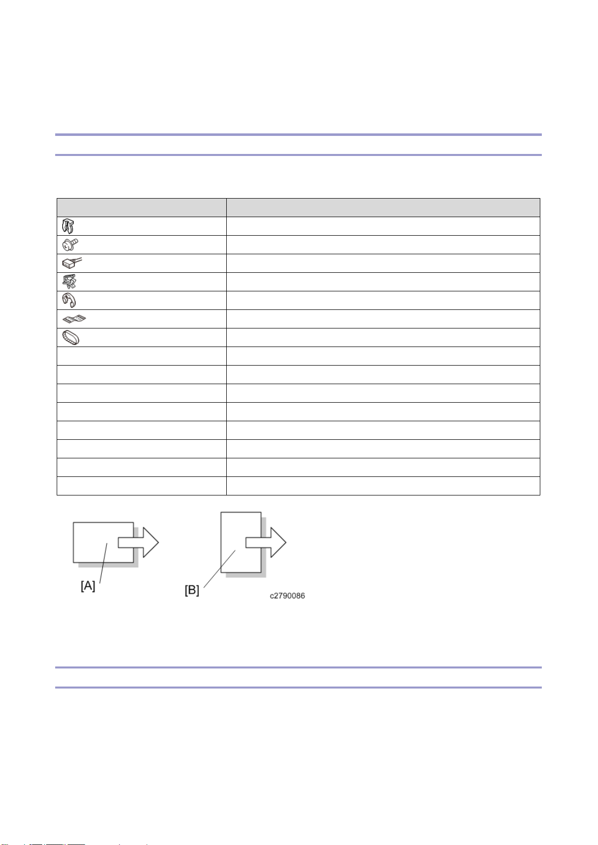
This manual uses several symbols and abbreviations. The meaning of those symbols and abbreviations
are as follows:
Symbol
What it means
Clip ring
Screw
Connector
Clamp
E-ring
Flat Flexible Cable
Timing Belt
SEF
Short Edge Feed
LEF
Long Edge Feed
K
Black
C
Cyan
M
Magenta
Y
Yellow
B/W, BW
Black and White
FC
Full color
[A] Short Edge Feed (SEF)
[B] Long Edge Feed (LEF)
Trademarks
Adobe, Acrobat, PageMaker, PostScript, and PostScript 3 are either registered trademarks or
trademarks of Adobe Systems Incorporated in the United States and/or other countries.
The Bluetooth® word mark and logos are registered trademarks owned by Bluetooth SIG, Inc. and any
use of such marks by Ricoh Company, Ltd. is under license.
Firefox and Thunderbird are registered trademarks of the Mozilla Foundation.

Dropbox is a registered trademark or trademark of Dropbox, Inc.
Google, Android, and Chrome are trademarks of Google Inc.
Java is a registered trademark of Oracle and/or its affiliates.
Macintosh, OS X, Bonjour, Safari, and TrueType are trademarks of Apple Inc., registered in the U.S.
and other countries.
Microsoft, Windows, Windows Server, Windows Vista, Internet Explorer, and Outlook are either
registered trademarks or trademarks of Microsoft Corp. in the United States and/or other countries.
PictBridge is a trademark.
QR Code is a registered trademark of DENSO WAVE INCORPORATED in Japan and in other
countries.
The SD and SD logo are trademarks of SD-3C, LLC.
UNIX is a registered trademark of The Open Group.
UPnP is a trademark of UPnP Implementers Corporation.
This product includes RSA BSAFE® Cryptographic software of EMC Corporation. RSA and BSAFE are
registered trademarks or trademarks of EMC Corporation in the United States and other countries.
The proper names of Internet Explorer 11 is as follows:
• Windows® Internet Explorer® 11
The proper names of the Windows operating systems are as follows:
• The product names of Windows Vista are as follows:
Microsoft® Windows Vista® Ultimate
Microsoft® Windows Vista® Business
Microsoft® Windows Vista® Home Premium
Microsoft® Windows Vista® Home Basic
Microsoft® Windows Vista® Enterprise
• The product names of Windows 7 are as follows:
Microsoft® Windows® 7 Home Premium
Microsoft® Windows® 7 Professional
Microsoft® Windows® 7 Ultimate
Microsoft® Windows® 7 Enterprise
• The product names of Windows 8 are as follows:

Microsoft® Windows® 8
Microsoft® Windows® 8 Pro
Microsoft® Windows® 8 Enterprise
• The product names of Windows 10 are as follows:
Microsoft® Windows® 10 Home Premium
Microsoft® Windows® 10 Pro
Microsoft® Windows® 10 Enterprise
Microsoft® Windows® 10 Education
• The product names of Windows Server 2003 are as follows:
Microsoft® Windows Server® 2003 Standard Edition
Microsoft® Windows Server® 2003 Enterprise Edition
• The product names of Windows Server 2003 R2 are as follows:
Microsoft® Windows Server® 2003 R2 Standard Edition
Microsoft® Windows Server® 2003 R2 Enterprise Edition
• The product names of Windows Server 2008 are as follows:
Microsoft® Windows Server® 2008 Standard
Microsoft® Windows Server® 2008 Enterprise
• The product names of Windows Server 2008 R2 are as follows:
Microsoft® Windows Server® 2008 R2 Standard
Microsoft® Windows Server® 2008 R2 Enterprise
• The product names of Windows Server 2012 are as follows:
Microsoft® Windows Server® 2012 Foundation
Microsoft® Windows Server® 2012 Essentials
Microsoft® Windows Server® 2012 Standard
• The product names of Windows Server 2012 R2 are as follows:
Microsoft® Windows Server® 2012 R2 Foundation
Microsoft® Windows Server® 2012 R2 Essentials
Microsoft® Windows Server® 2012 R2 Standard
• The product names of Windows Server 2016 R2 are as follows:
Microsoft® Windows Server® 2016 R2 Essentials
Microsoft® Windows Server® 2016 R2 Standard
Other product names used herein are for identification purposes only and might be trademarks of their
respective companies. We disclaim any and all rights to those marks.
Microsoft product screen shots reprinted with permission from Microsoft Corporation.


1
Table of Contents
1. Detailed Descriptions .......................................................................................................................... 3
Changes from the Previous Machine ..................................................................................................... 3
Specifications.......................................................................................................................................... 4
Parts Layout ............................................................................................................................................ 5
Mechanism ............................................................................................................................................. 8
Tray full detection mechanism ............................................................................................................ 8
Straight paper exit/shift paper exit mechanism .................................................................................. 9
Shift mechanism ............................................................................................................................... 10
Paper exit roller/paper exit belt release mechanism ........................................................................ 11
Staple eject mechanism ................................................................................................................... 13
Junction gate/trailing edge presser mechanism ............................................................................... 16
Sub-scan direction (transport direction) jogger mechanism ............................................................. 17
Paper detection on the stack guide plate ......................................................................................... 18
Sheet edge face alignment mechanism (main-scan direction) ........................................................ 18
Stapler Mechanism ........................................................................................................................... 19
Stapler Movement Mechanism ......................................................................................................... 20
2. Replacement and Adjustment .......................................................................................................... 21
Removing the Internal Finisher ............................................................................................................ 21
Stapler Unit ........................................................................................................................................... 23
Stapler Unit ....................................................................................................................................... 23
Exterior Covers and Tray ..................................................................................................................... 25
Finisher Front Cover ......................................................................................................................... 25
Finisher Upper Cover........................................................................................................................ 25
Rear Cover ........................................................................................................................................ 25
Paper Exit Cover ............................................................................................................................... 26
Paper Exit Tray ................................................................................................................................. 27
Sensors and Switch .............................................................................................................................. 28
Entrance Sensor (S6) ....................................................................................................................... 28
Sub-scan Registration Sensor (S2) .................................................................................................. 28
Door Switch (SW1) ........................................................................................................................... 29
Shift HP Sensor (S7) ........................................................................................................................ 30
Paper Exit Sensor (S3) ..................................................................................................................... 30
Paper Exit Pressure HP Sensor (S8) ............................................................................................... 31
Junction Gate Motor HP Sensor (S1) ............................................................................................... 32
Paper Exit Full Sensor 1 (S4), Paper Exit Full Sensor 2 (Staple) (S5) ............................................ 32
Stapler Drive HP Sensor (S9) ........................................................................................................... 33
Motors ................................................................................................................................................... 34

2
Shift Motor (STM3) ........................................................................................................................... 34
Transport Motor (STM2) ................................................................................................................... 34
Junction Gate Motor (STM1) ............................................................................................................ 35
Paper Exit Pressure Motor (STM4) .................................................................................................. 35
Stapler Drive Motor (DCM1) ............................................................................................................. 36
Board .................................................................................................................................................... 38
Controller Board (PCB1) ................................................................................................................... 38
1.Detailed Descriptions
3
1. Detailed Descriptions
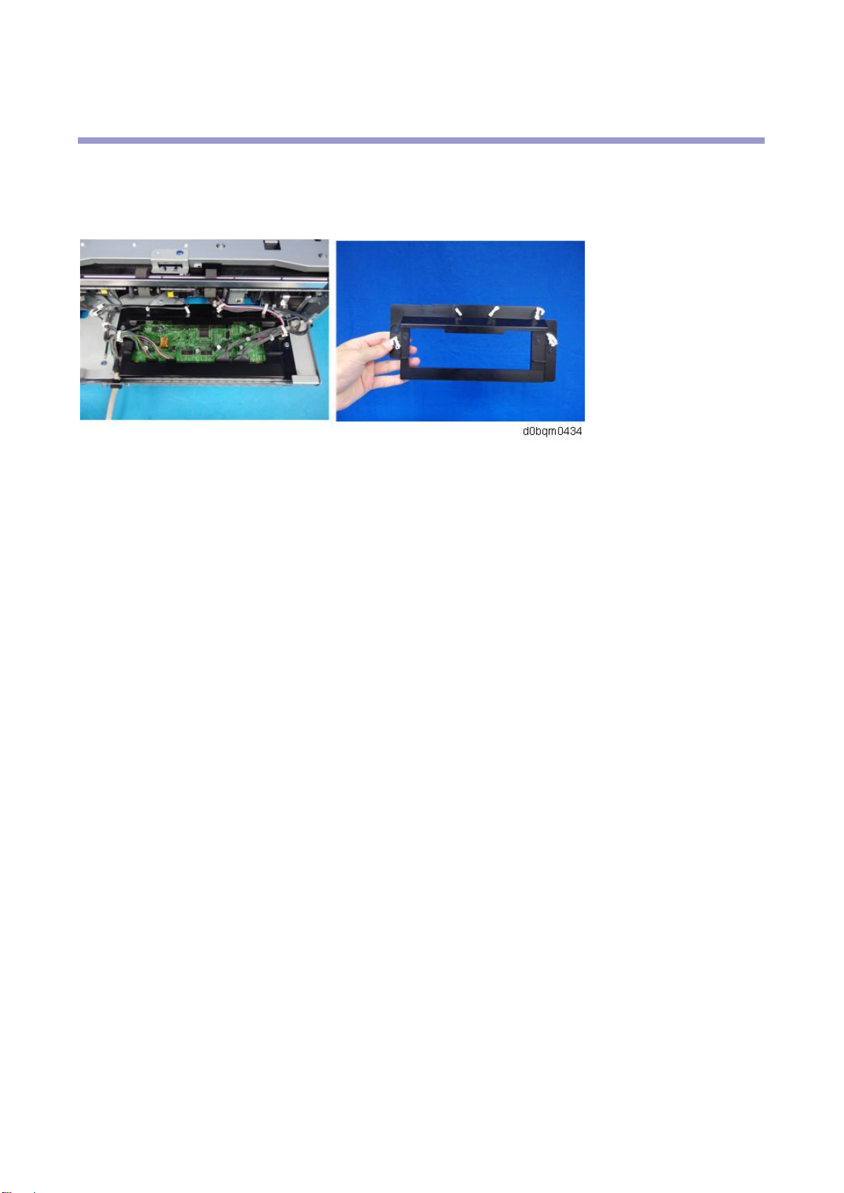
Changes from the Previous Machine
A cover is attached to the control board.

1.Detailed Descriptions
4
Specifications
Item
Specification
Paper size
A3 SEF, A4, B4 JIS SEF, B5 JIS, 11 × 17 SEF, 81/2 × 14 SEF, 81/2 × 13
SEF, 81/2 × 11, 81/4 × 14 SEF, 81/4 × 13 SEF, 71/4 × 101/2, 8K SEF, 16K,
81/2 × 132/
5
SEF, Custom Size
Paper weight
52-300 g/m2 (14 lb. Bond-110 lb. Cover)
Paper sizes that can be
shifted
A3 SEF, A4, B4 JIS SEF, B5 JIS, 11 × 17 SEF, 81/2 × 14 SEF, 81/2 × 13
SEF, 81/2 × 11, 81/4 × 14 SEF, 81/4 × 13 SEF, 71/4 × 101/2, 8K SEF, 16K,
81/2 × 132/
5
SEF, Custom Size
Paper weight that can be
shifted
64-80 g/m2 (17-20 lb. Bond)
Stack capacity (80 g/m2,
20 lb. Bond)
• 250 sheets or more: A4 Portrait, B5 JIS, 8
1
/
2
× 11
• 125 sheets: A3 SEF-A4 SEF, B4 JIS SEF, 8
1
/2 × 14 SEF, 11 × 17
SEF
Staple paper size
A3 Landscape, A4, B4 JIS Landscape, B5 JIS, 11 × 17 Landscape, 81/2 ×
14 Landscape, 81/2 × 13 Landscape, 81/2 × 11, 81/4 × 14 Landscape, 81/4
× 13 Landscape, 71/4 × 101/2, 8K Landscape, 16K, 81/2 × 132/5
Landscape, Custom Size
Staple paper weight
64-80 g/m2 (17-20 lb. Bond)
Staple capacity (80 g/m2,
20 lb. Bond)
5 sheets
Power consumption
30 W or less
Power source
24V DC (supplied from main frame), 5V SC (generated by FIN board),
SELV (super-low voltage secondary power supply)
Dimensions
(width×depth×height)
435 × 515 × 150 mm (17.2 × 20.3 × 6.0 inches)
Mass
Approx. 10 kg (22.1 lb.)
1.Detailed Descriptions
5
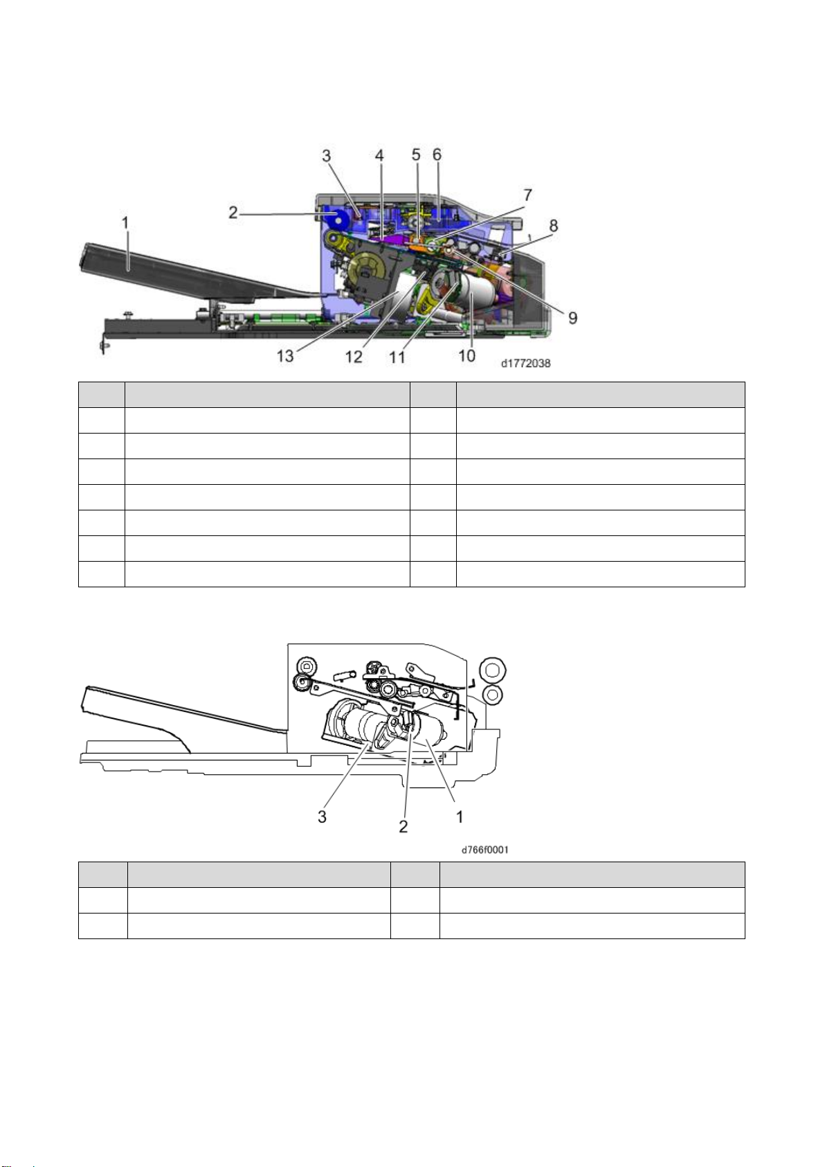
Parts Layout
No.
Description
No.
Description
1
Paper exit tray
8
Entrance sensor (S6)
2
Paper exit roller/paper exit belt
9
Trailing edge presser
3
Paper exit sensor (S3)
10
Stapler drive motor (DCM1)
4
Junction gate
11
Stapler
5
Shift roller
12
Stapler drive HP sensor (S9)
6
Sub-scan registration sensor (S2)
13
Paper exit pressure motor (STM4)
7
Reverse roller
-
-
No.
Description
No.
Description
1
Stapler drive motor (DCM1)
3
Paper exit pressure motor (STM4)
2
Stapler drive HP Sensor (S9)
-
-

1.Detailed Descriptions
6
No.
Description
No.
Description
4
Shift HP sensor (S7)
7
Door switch (SW1)
5
Junction gate motor HP sensor (S1)
8
Shift motor (STM3)
6
Entrance sensor (S6)
-
- No.
Description
No.
Description
9
Sub-scan registration sensor (S2)
12
Paper exit sensor (S3)
10
Paper exit pressure HP sensor (S8)
13
Paper exit full sensor 2 (Staple) (S5)
11
Paper exit full sensor 1 (S4)
-
-
1.Detailed Descriptions
7
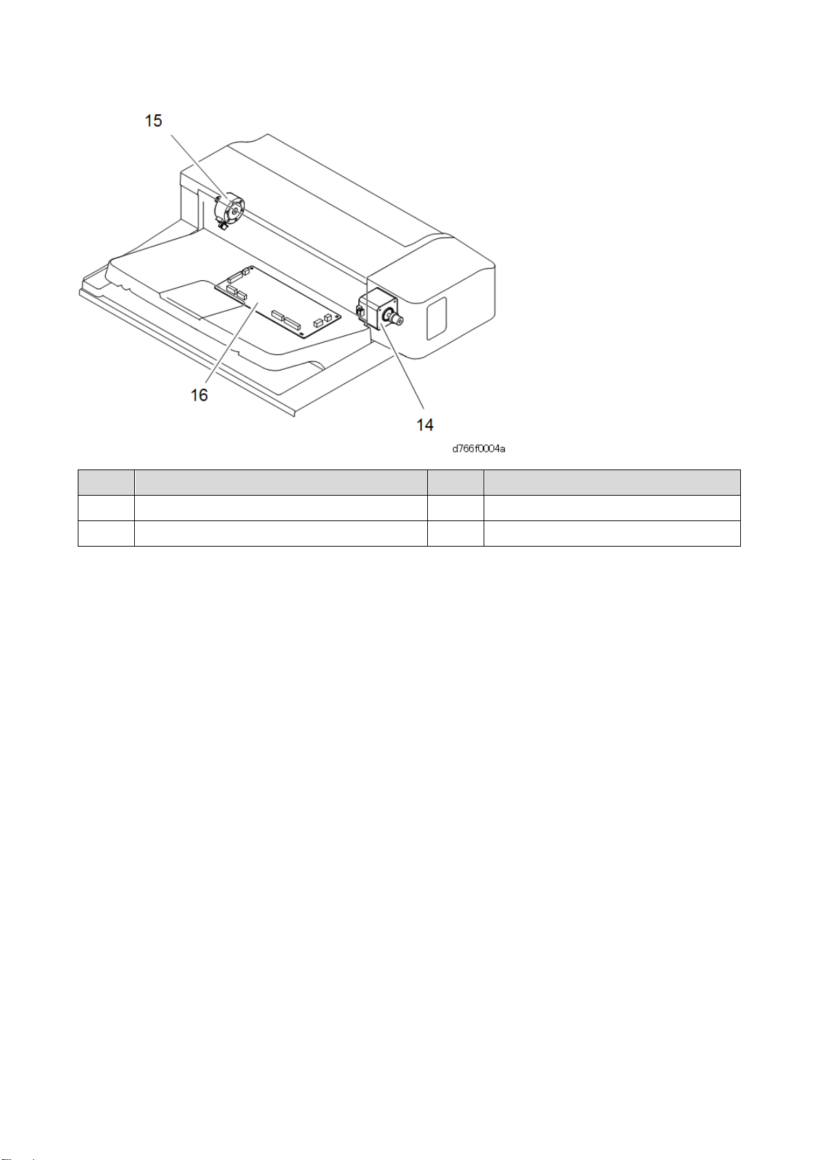
No.
Description
No.
Description
14
Transport motor (STM2)
16
Controller board (PCB1)
15
Junction gate motor (STM1)
-
-
1.Detailed Descriptions
8
Mechanism
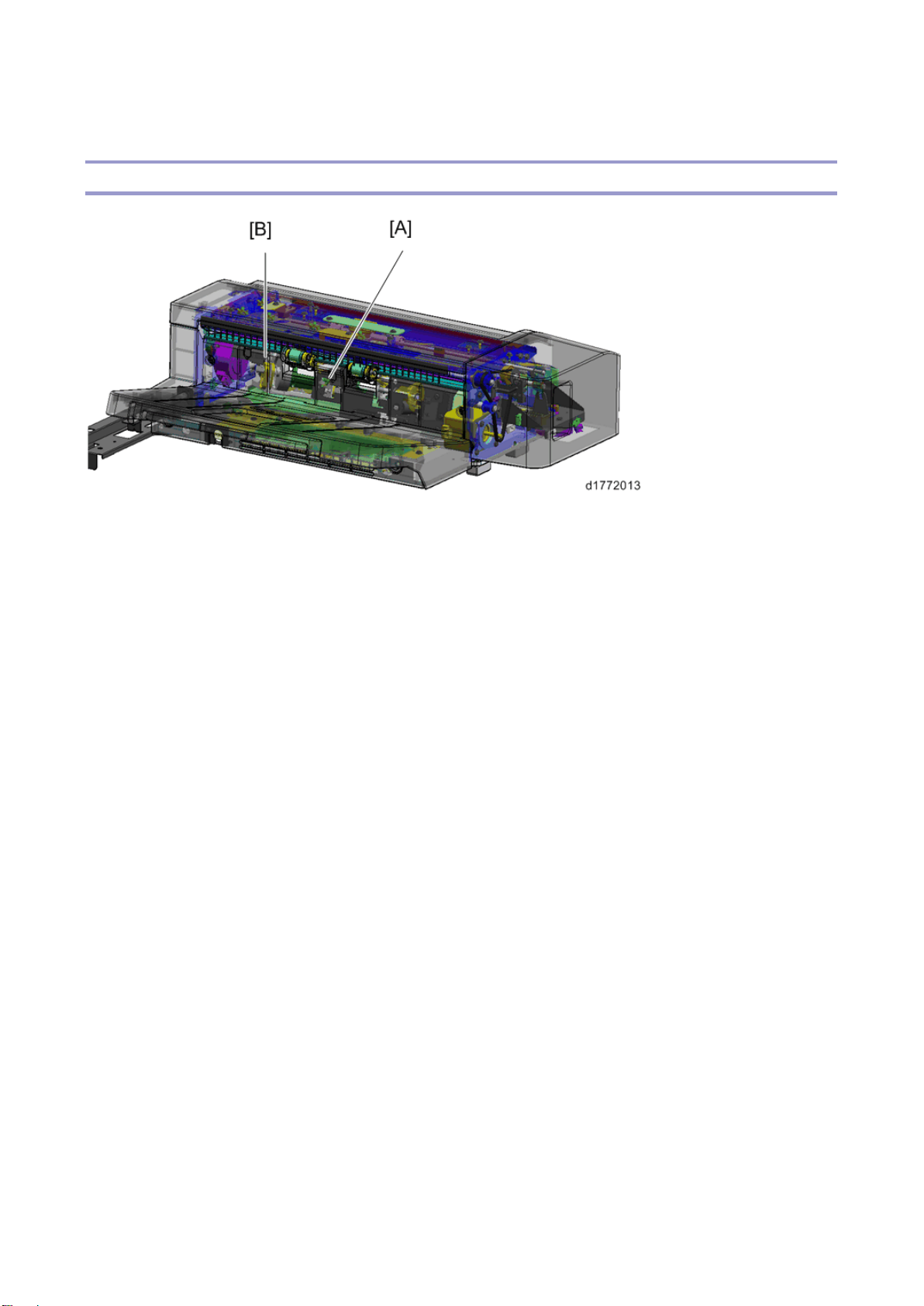
Tray full detection mechanism
When the paper exit full sensor 1 [A] or the paper exit full sensor 2 (staple) [B] detects paper, the paper
exit tray is full. Paper feed is stopped temporarily while the tray is full, and is restarted after the paper is
removed.
The paper exit full sensor 1 is at the center of the main scan (side-to-side), and detects the total
quantity of paper in the paper exit tray.
If the paper is stapled, the height of the paper around the stapled area is higher than that of the other
areas. The paper exit full sensor 2 (staple) is located at the stapling area, and detects the quantity of
stapled paper.
 Loading...