

Page 1
SERVICE MANUAL
(Machine code: C231)
Page 2

IMPORTANT SAFETY NOTICES
PREVENTION OF PHYSICAL INJURY
1. Before disassembling or assembling parts of the printer and peripherals, make
sure that the power cord is unplugged.
2. The wall outlet should be near the printer and easily accessible.
3. If any adjustment or operation check has to be made with exterior covers off or
open while the main switch is turned on, keep hands away from electrified or
mechanically driven components.
HEALTH SAFETY CONDITIONS
1. If you get ink in your eyes by accident, try to remove it with eye drops or flush
with water as first aid. If unsuccessful, get medical attention.
2. If you ingest ink by accident, induce vomiting by sticking a finger down your
throat or by giving soapy or strong salty water to drink.
OBSERVANCE OF ELECTRICAL SAFETY STANDARDS
1. The printer and its peripherals must be installed and maintained by a customer
service representative who has completed the training course on those models.
CAUTION
I
The RAM has a lithium battery which can explode if handled incorrectly.
Replace only with the same type of RAM. Do not recharge or burn this
battery. Used RAM's must be handled in accordance with local regulations.
ATTENTION
I
La carte RAM comporte une pile au lithium qui présente un risque
d'explosion en cas de mauvaise manipulation. Remplacer la pile
uniquement par une carte RAM identique. Ne pas recharger ni brûler cette
pile. Les cartes RAM usagées doivent être éliminées conformément aux
réglementations locales.
1
Page 3

SAFETY AND ECOLOGICAL NOTES FOR DISPOSAL
1. Dispose of replaced parts in accordance with local regulations.
2. Used ink and masters should be disposed of in an environmentally safe
manner and in accordance with local regulations.
3. When keeping used lithium batteries (from the main processing units) in order
to dispose of them later, do not store more than 100 batteries (from the main
processing units) per sealed box. Storing larger numbers or not sealing them
apart may lead to chemical reactions and heat build-up.
2
Page 4

1 July, 1998 SPECIFICATION
1. OVERALL INFORMATION
1.1 SPECIFICATION
Configuration: Desktop
Master Processing: Digital with 300 dpi thermal head
Scanning (Pixel Density): Contact image sensor (300 dpi), with xenon lamp
* In Fine mode, 400 dpi in the sub-scanning
resolution
Printing Process: Fully automatic one-drum stencil system
Original Type: Sheet/Book
In Platen Mode: Document size:
Maximum 257 x 364 mm [10.2" x 14.4"]
Thickness: Less than 30 mm
Weight: Less than 5 kg
In ADF Mode: Document size:
Maximum 257 x 364 mm [10.2" x 14.4"]
Minimum 148 x 105 mm [5.8" x 4.1"]
Overall
Information
Document weight:
50 - 90 g/m2[13.3 - 23.9 lb]
(40 - 120 g/m2[10.6 - 31.9 lb]
in single sheet feed)
ADF capacity:
30 sheets (using 20 lb or 80 g/m2 paper)
Reproduction Ratios: Inch version Others
Full Size: 100% 100%
Reduction: 65% 71%
74% 82%
77% 87%
93% 93%
Enlargement: 121% 115%
129% 122%
155% 141%
Image Modes: Letter, Photo, Letter/Photo, Fine, Tint
1-1
Page 5

SPECIFICATION 1 July, 1998
Printing Area:
(At 20 °C/ 65 % RH)
B4 size drum models:
250 mm x 355 mm
Legal size drum models:
210 mm x 355 mm [8.2" x 13.9"]
A4 size drum models:
210 mm x 288 mm [8.2" x 11.3"]
Edge Margins: Leading edge:
5 ± 3 mm (At the "0" position of Image Shift mode)
Trailing edge:
2 mm
Print Paper Size: Minimum: 90 mm x 148 mm [3.6" x 5.9"]
Maximum: 267 mm x 390 mm [10.5" x 15.3"]
Print Paper Weight: 47.1 g/m2 to 157.0 g/m2 [12.5 lb to 41.7 lb]
Printing Speed: 80, 100, 120 sheets/minute (3 steps)
Master Process Time: Platen mode:
Less than 28 seconds (A4 paper)
ADF mode:
Less than 30 seconds (A4 paper)
Master Eject Box Capacity: 40 masters (Normal conditions)
(30 masters at low temperatures)
Side Registration Adjustable
± 10 mm
Range:
Vertical Registration Adjustable
± 10 mm
Range:
Paper Feed Table Capacity: 1000 sheets (80 g/m2 / 20 lb)
Paper Delivery Table Capacity: 1000 sheets (80 g/m2/ 20 lb)
Power Source: 110/120 V, 50/60 Hz: 2.5 A
220 - 240 V, 50/60 Hz: 1.5 A
Maximum Power Consumption: 250 W
Noise Emission:
(At operation position)
At 80 rpm printing speed: 71 dB
At 100 rpm printing speed: 72 dB
At 120 rpm printing speed: 72 dB
1-2
Page 6

1 July, 1998 SPECIFICATION
Weight: 65 kg [143.3 lb]
68 kg [149.9 lb] with ADF
Dimensions:
(Width x Depth x Height)
Trays closed: 594 mm x 601 mm x 567 mm
With ADF:
594 mm x 601 mm x 617 mm
Trays open: 1187 mm x 601 mm x 567 mm
With ADF:
1187 mm x 601 mm x 617 mm
Master Type: Master for B4 drum
Thermal master roll type:
280 mm width, 125 m/roll
Yield:
260 masters/roll
Max run length per master:
2,000 prints
Overall
Information
Master for A4/Legal drum
Thermal master roll type:
240 mm width, 125 m/roll
Yield:
300 masters/roll (A4 drum)
260 masters/roll (Legal drum)
Max run length per master:
2,000 prints
Master Storage Conditions: Temperature:
0 °C to 40 °C
Humidity:
10% to 95% RH
Recommended maximum storage period:
One year after production date
* Avoid locations exposed to direct sunlight.
1-3
Page 7

SPECIFICATION 1 July, 1998
Ink Type 600 ml cartridge type
Available colors:
Black, Red, Blue, Green, Brown
Ink Storage Conditions: Temperature:
-5 °C to 40 °C
(Optimum conditions: 15 °C to 25 °C)
Humidity:
10% to 95% RH
(Optimum conditions: 20% to 70% RH)
Recommended maximum storage period:
One year after production date
* Avoid locations exposed to direct sunlight.
Available Options
· Color Drum
· Document Feeder
· Key Counter
· Tape Marker
· PC Controller
1-4
Page 8
1 July, 1998 GUIDE TO COMPONENTS AND THEIR FUNCTION
1.2 GUIDE TO COMPONENTS AND THEIR FUNCTION
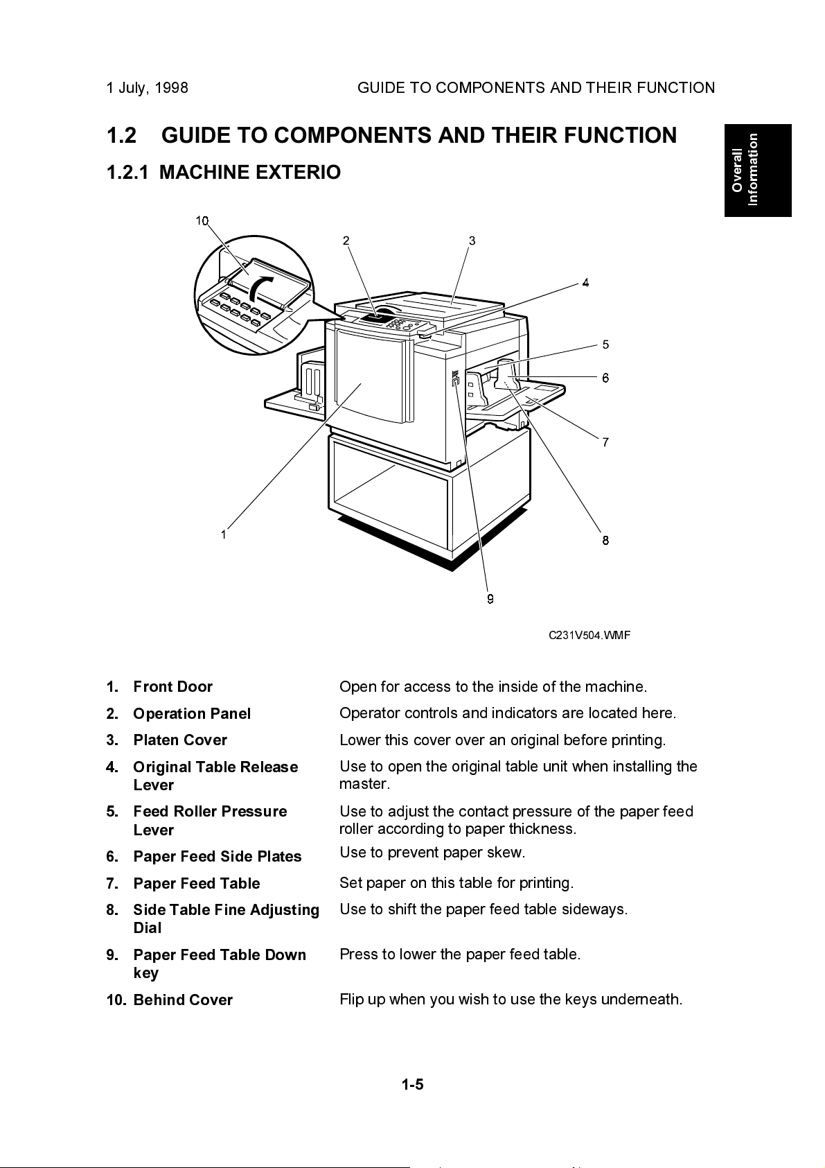
1.2.1 MACHINE EXTERIOR
Overall
Information
1. Front Door
2. Operation Panel
3. Platen Cover
4. Original Table Release
Lever
5. Feed Roller Pressure
Lever
6. Paper Feed Side Plates
7. Paper Feed Table
8. Side Table Fine Adjusting
Dial
9. Paper Feed Table Down
key
10. Behind Cover
C231V504.WMF
Open for access to the inside of the machine.
Operator controls and indicators are located here.
Lower this cover over an original before printing.
Use to open the original table unit when installing the
master.
Use to adjust the contact pressure of the paper feed
roller according to paper thickness.
Use to prevent paper skew.
Set paper on this table for printing.
Use to shift the paper feed table sideways.
Press to lower the paper feed table.
Flip up when you wish to use the keys underneath.
1-5
Page 9
GUIDE TO COMPONENTS AND THEIR FUNCTION 1 July, 1998
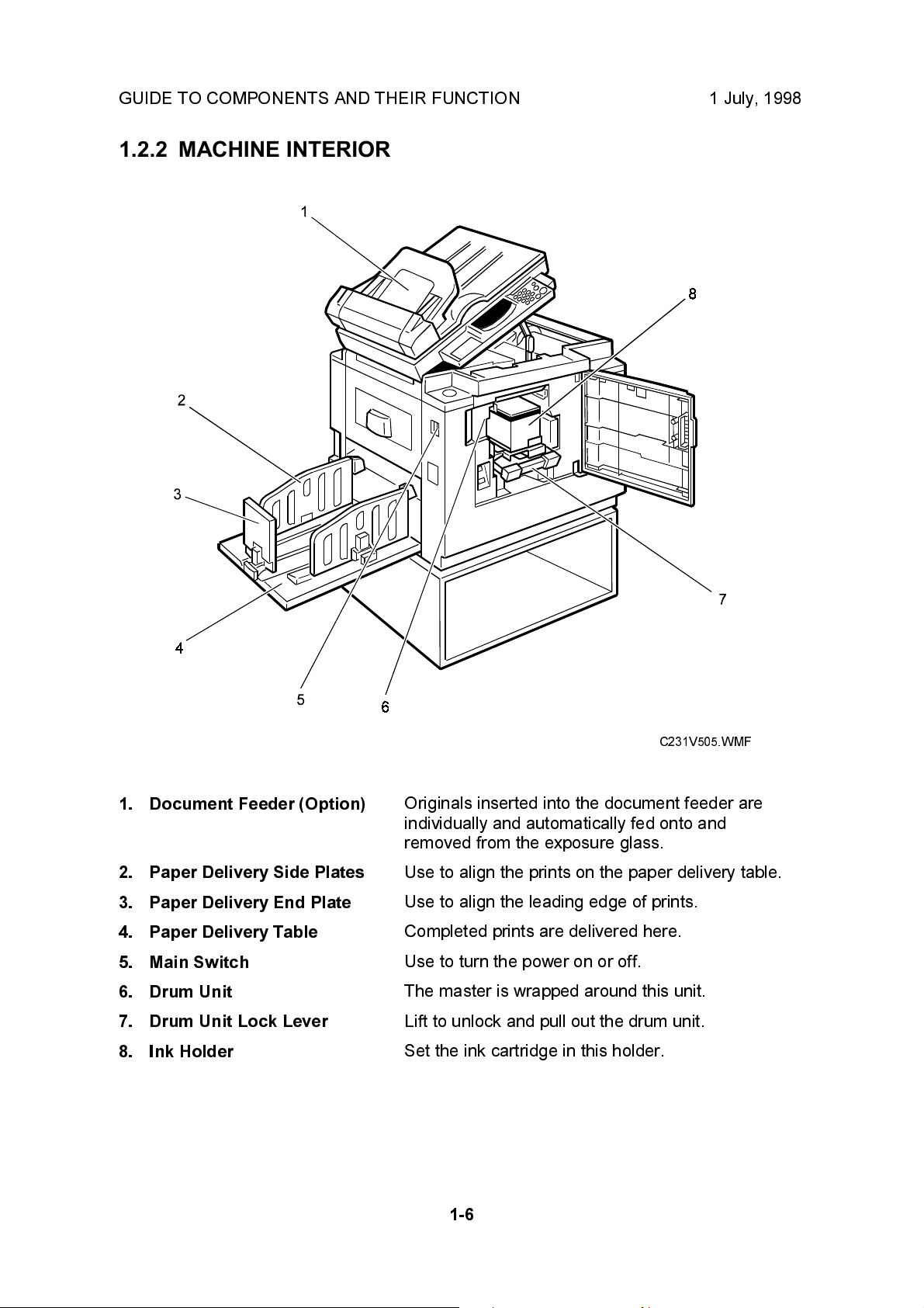
1.2.2 MACHINE INTERIOR
1. Document Feeder (Option)
2. Paper Delivery Side Plates
3. Paper Delivery End Plate
4. Paper Delivery Table
5. Main Switch
6. Drum Unit
7. Drum Unit Lock Lever
8. Ink Holder
C231V505.WMF
Originals inserted into the document feeder are
individually and automatically fed onto and
removed from the exposure glass.
Use to align the prints on the paper delivery table.
Use to align the leading edge of prints.
Completed prints are delivered here.
Use to turn the power on or off.
The master is wrapped around this unit.
Lift to unlock and pull out the drum unit.
Set the ink cartridge in this holder.
1-6
Page 10
1 July, 1998 GUIDE TO COMPONENTS AND THEIR FUNCTION
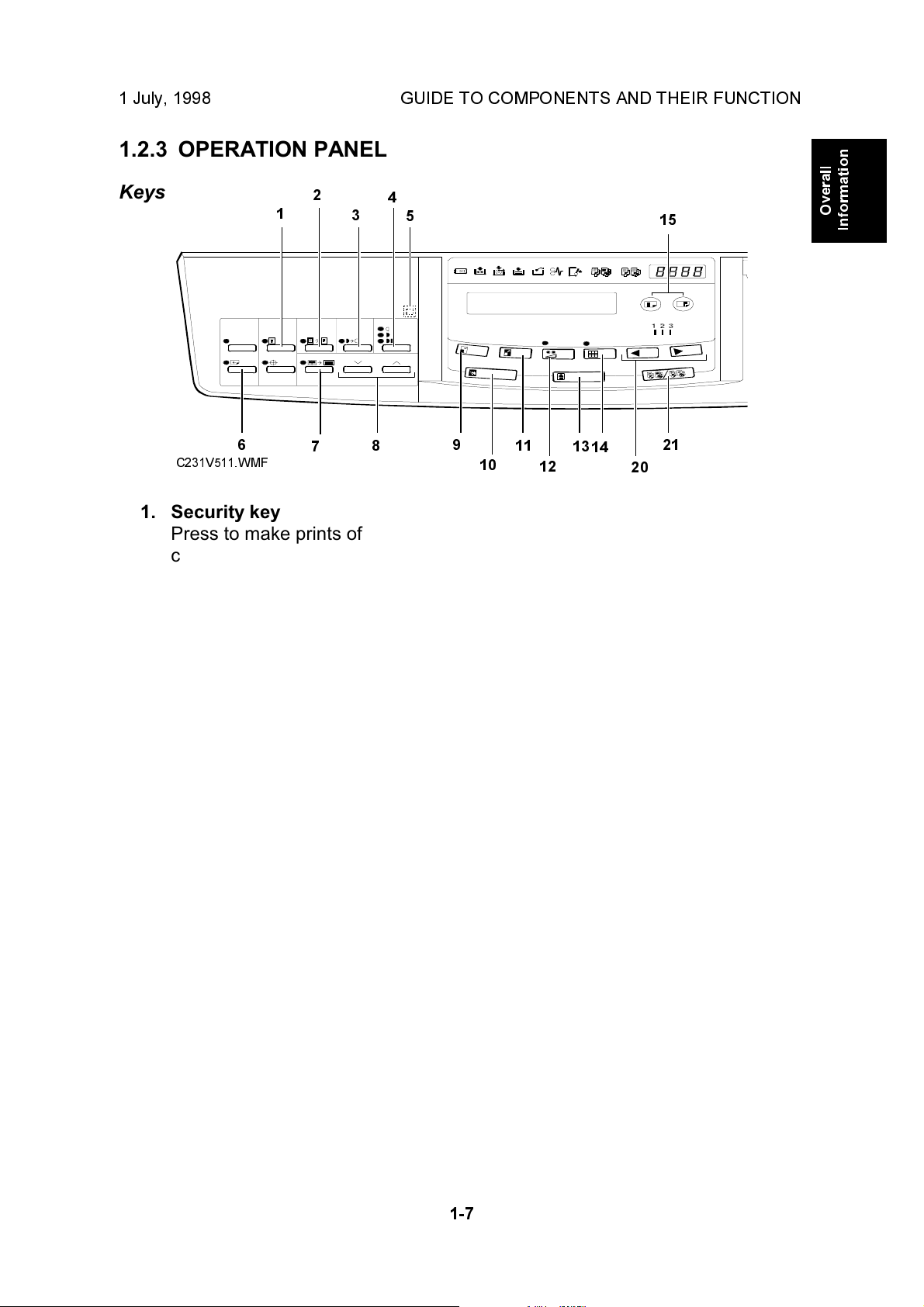
1.2.3 OPERATION PANEL
Keys
6
C231V511.WMF
2
1
7
1. Security key
Press to make prints of
confidential documents.
2. Paste Shadow Erase key
Press to erase the shadows on
images of pasted originals.
3. Tint key
Press to make prints in grey.
(This is the Tint/Economy key for
the China version.)
4
3
5
8
9
10
11
12
13
14
15
21
20
Overall
Information
7. Center/Edge Erase key
Press to print book originals that
have a solid image on the center
or edges.
8. Scroll keys
Press to select size and direction
of paper or original for
Center/Edge Erase.
9. Reduce key
Press to reduce the image.
4. Image Density key
Press to make prints darker or
lighter.
5. Check Indicator
This indicator lights when you
have selected one or more of the
functions accessed by lifting the
behind cover and pressing the
keys underneath (e. g. Security
key, Paste Shadow Erase key
etc.). This lets you know whether
one or more of these functions is
selected, even if the cover is
lowered.
6. Skip Feed key
Press to select skip feed printing.
10. Full Size key
Press to make full size prints.
11. Enlarge key
Press to enlarge the image.
12. Economy key
Press to save ink. (This is the
Combine 2 Originals key for the
China version.)
13. Type of Original key
Press to select Letter, Photo, or
Letter/Photo mode.
14. Fine key
Press to select fine image mode.
15. Image Position key
Press to shift the image forwards
or backwards.
1-7
Page 11
GUIDE TO COMPONENTS AND THEIR FUNCTION 1 July, 1998
16
17
18
19
21
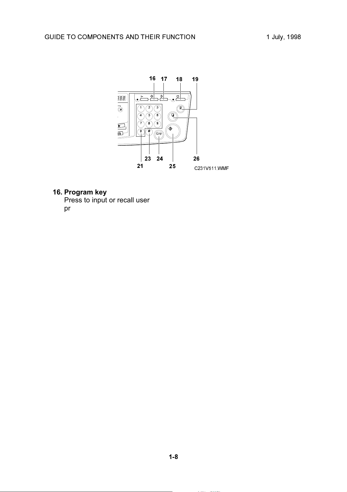
16. Program key
Press to input or recall user
programs.
17. Clear Modes key
Press to clear the previously
entered job settings.
18. Auto Cycle key
Use to process the master and
make prints automatically.
19. Proof key
Press to make proof prints.
20. Speed keys
Press to adjust the printing
speed.
21. Memory/Class key
Press to select Memory or Class
mode.
23
24
26
25
C231V511.WMF
22. Number keys
Press to enter the desired
number of prints and data for
selected modes.
23. # key
Use to enter data in selected
modes.
24. Clear/Stop key
While entering numbers, press to
cancel a number you have
entered. While copying, press to
stop copying.
25. Start key
Press to make a master.
26. Print key
Press to start printing.
1-8
Page 12
1 July, 1998 GUIDE TO COMPONENTS AND THEIR FUNCTION
Indicators
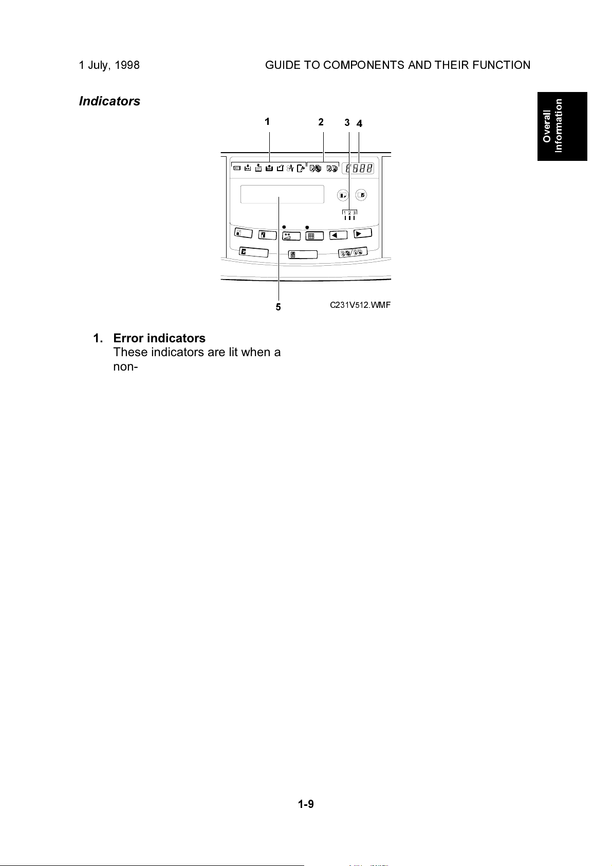
1. Error indicators
These indicators are lit when a
non-standard condition occurs
within the machine.
2. Memory/Class Indicator
Shows the number entered in
Memory or Class mode.
1
5
2
3
4
C231V512.WMF
Overall
Information
4. Counter
Displays the number of prints
entered. While printing, it shows
the number of prints remaining.
5. Guidance Display
Display the machine's condition.
3. Speed indicator
These indicators show the
printing speed that is selected.
1-9
Page 13
PRINTING PROCESS 1 July, 1998
1.3 PRINTING PROCESS
2
3
1
C231V500.WMF
654
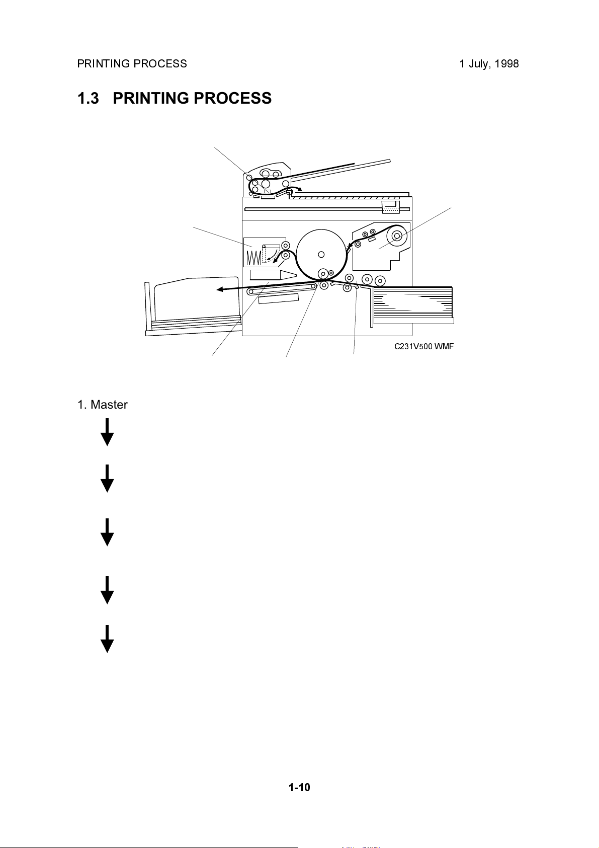
1. Master Eject: Ejects the used master wrapped around the drum
into the master eject box.
2. Scanning: The scanner, which is composed of the contact
image sensor (CIS) and xenon lamp, scans the
original image.
3. Master Feeding: Converts the image signal read by the CIS into digital
signals and sends them to the thermal head to
develop the image on the master. The master then
wraps around the drum.
4. Paper Feeding: Sends paper to the drum section.
5. Printing: Presses the paper fed from the paper feed section to
the drum. This transfers the ink to the paper through
the drum screen and the master.
6. Paper Delivering: Peels the printed paper with the exit pawl and air
knife, and ejects the paper onto the paper delivery
table.
1-10
Page 14
1 July, 1998 MECHANICAL COMPONENT LAYOUT
1.4 MECHANICAL COMPONENT LAYOUT
1232524232221
20
4
19
5
18
6
7
17
8
9
Overall
Information
16 13
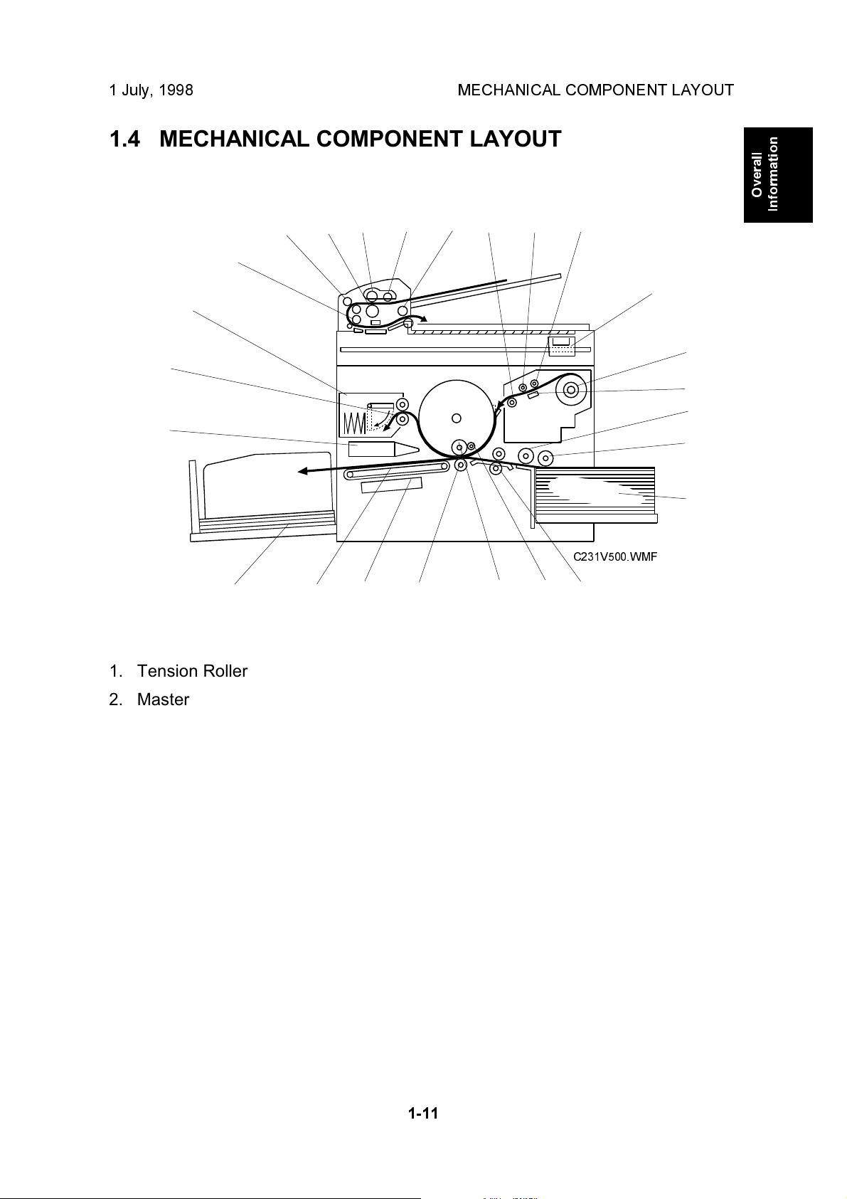
1. Tension Roller
2. Master Feed Roller
3. Platen Roller
4. Scanner
5. Master Roll
6. Thermal Head
7. Paper Feed Roller
8. Paper Pick-up Roller
9. Paper Table
10. Registration Roller
11. Doctor Roller
C231V500.WMF
11121415
10
14. Vacuum Fan Motor
15. Transport Belts
16. Paper Delivery Table
17. Air Knife Fan Motor
18. Master Eject Roller
19. Master Eject Box
20. DF R1 Roller
21. DF R0 Roller
22. DF Separation Roller
23. DF Document Feed Roller
24. DF Pick-up Roller
12. Ink Roller
13. Press Roller
25. DF R2 Roller
1-11
Page 15
ELECTRICAL COMPONENT LAYOUT 1 July, 1998
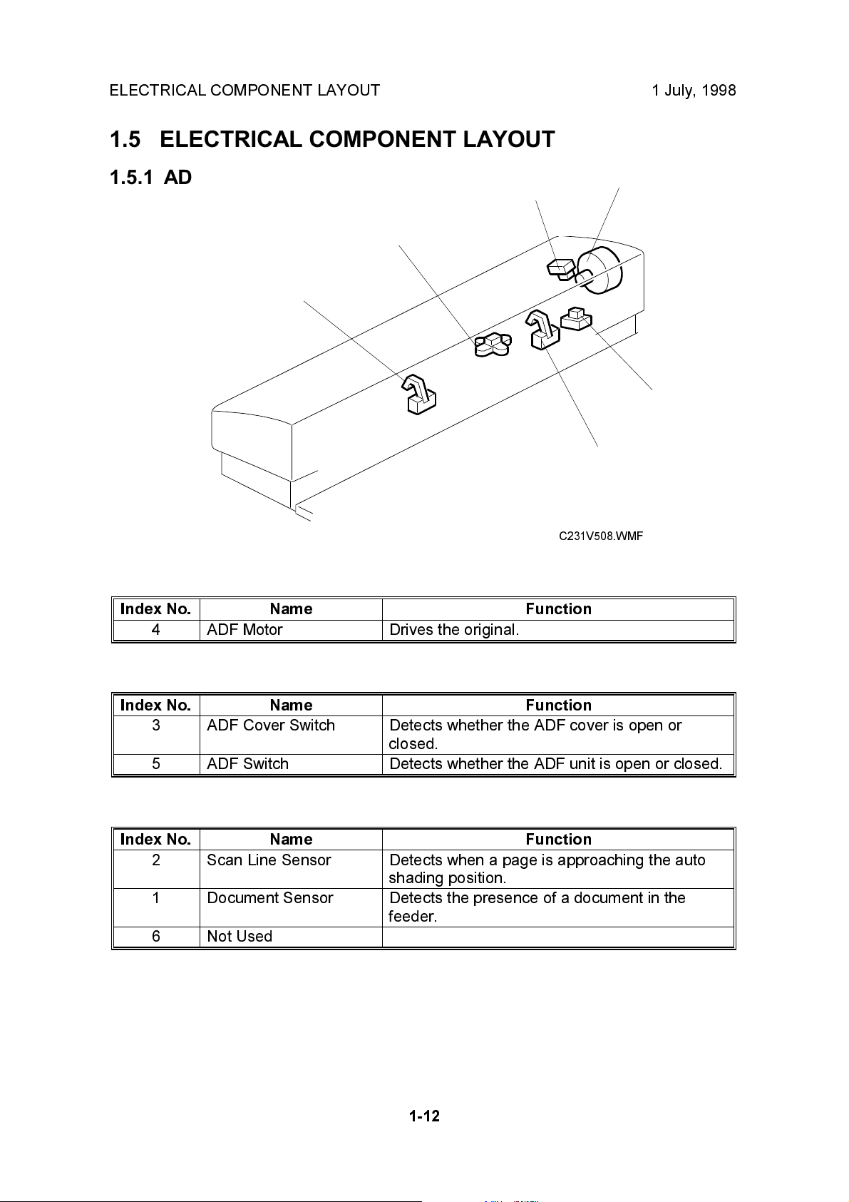
1.5 ELECTRICAL COMPONENT LAYOUT
1.5.1 ADF
3
2
1
Motors
Index No. Name Function
4 ADF Motor Drives the original.
4
5
6
C231V508.WMF
Switches
Index No. Name Function
3 ADF Cover Switch Detects whether the ADF cover is open or
closed.
5 ADF Switch Detects whether the ADF unit is open or closed.
Sensors
Index No. Name Function
2 Scan Line Sensor Detects when a page is approaching the auto
shading position.
1 Document Sensor Detects the presence of a document in the
feeder.
6 Not Used
1-12
Page 16
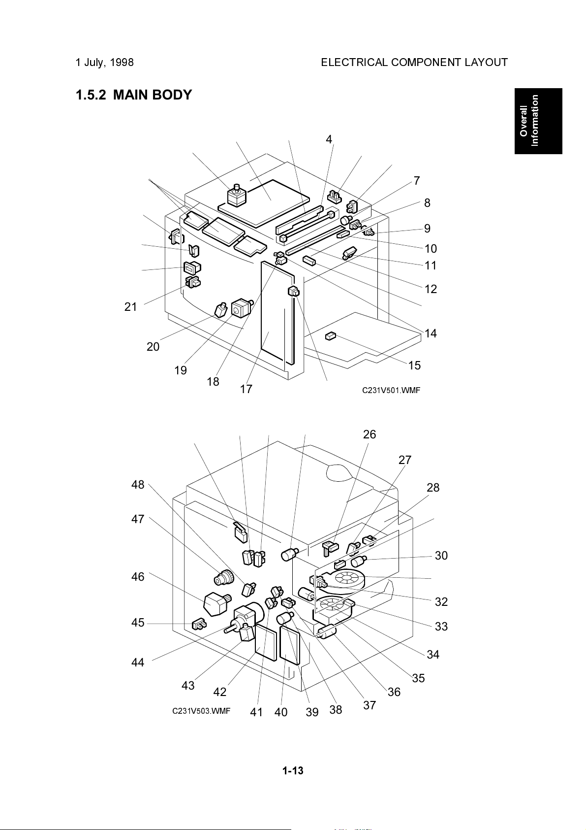
1 July, 1998 ELECTRICAL COMPONENT LAYOUT
1.5.2 MAIN BODY
24
23
22
21
25
20
19
1
2
3
4
5
Overall
Information
6
7
8
9
10
11
12
13
14
15
18
17
16
C231V501.WMF
48
47
46
45
44
49
43
C231V503.WMF
42
50
51
52
26
27
28
29
30
31
32
33
34
35
36
38
394041
37
1-13
Page 17

ELECTRICAL COMPONENT LAYOUT 1 July, 1998
Boards
Index No. Name Function
2 Main Processing Unit
(MPU)
3 Lamp Stabilizer This supplies power to the xenon lamp.
17 Power Supply Unit Provides dc power to the system.
25 Operation Panel Boards These boards control the operation panel.
4 Contact Image Sensor
and Xenon Lamp
40 Noise Filter Board Filters out electrical noise on the ac power input
42 Main Motor Control
Board
Controls all machine functions both directly and
through other boards.
This sensor reads and converts the light
reflected from the document into an analog
video signal. It uses an RMLA (Roof Mirror Lens
Array) sensor unit.
The xenon lamp that illuminates the document is
contained in this unit.
lines.
Controls the main motor speed.
Motors
Index No. Name Function
7 Master Feed Motor Feeds the master to the drum.
18 Cutter Motor Cuts the master.
19 Registration Motor Feeds the paper to align it with the master on
the drum.
1 Scanner Motor Stepper motor drives the book scanner.
30 Master Eject Motor Sends used masters into the master eject box.
31 Air Knife Fan Motor Rotates the fan to provide air to separate the
leading edge of the paper from the drum.
34 Pressure Plate Motor Raises and lowers the pressure plate.
35 Vacuum Fan Motor Provides suction so that paper is held firmly on
the transport belt.
36 Paper Transport Motor Transports the printed paper.
39 Clamper Motor Opens or closes the drum master clamper.
44 Main Motor Drives paper feed mechanisms and the drum.
46 Paper Table Motor Raises and lowers the paper table.
52 Ink Pump Motor Drives the ink pump.
1-14
Page 18

1 July, 1998 ELECTRICAL COMPONENT LAYOUT
Solenoids
Index No. Name Function
43 Rear Pressure Release
Solenoid
20 Front Pressure Release
Solenoid
Releases the press roller to apply printing
pressure.
Releases the press roller to apply printing
pressure.
Switches
Index No. Name Function
49 Scanner Unit Safety
Switch
9 Master Making Unit
Cover Safety Switch
16 Table Lowering Switch Lowers the paper table.
21 Test Switch Releases the cover safety functions. (See the
23 Door Safety Switch Checks whether the front door is properly
24 Main Switch Turns the power on or off.
Checks whether the scanner unit is properly set.
Checks whether the cover on the master making
unit is properly closed.
notes below this table.)
closed.
Overall
Information
NOTE:
When you use this test switch, be sure to return it to the default position
after servicing.
Sensors
Index No. Name Function
50 Master Eject Position
Sensor
51 Paper Exit Timing
Sensor
48 Feed Start Timing
Sensor
26 Master Eject Sensor Detects used master misfeeds.
28 Pressure Plate Limit
Sensor
27 Pressure Plate Home
Position Sensor
29 Drum Master Sensor Detects if there is a master on the drum.
32 Eject Box Set Sensor Checks if the master eject box is set.
33 Paper Exit Sensor Detects paper misfeeds at the exit.
37 2nd Feed Timing
Sensor
38 Clamper Open Sensor Detects if the clamper is in the open position.
41 Clamper Close Sensor Detects if the clamper is in the closed position.
45 Table Lower Limit
Sensor
Detects when the drum is at the master eject
position.
Determines the paper exit misfeed check timing.
Determines the paper feed start timing.
Detects if the pressure plate is in the lowest
position.
Detects if the pressure plate is at the home
position.
Determines the paper misfeed check timing at
the paper registration area.
Detects when the paper table is at its lower limit
position.
1-15
Page 19

ELECTRICAL COMPONENT LAYOUT 1 July, 1998
Index No. Name Function
5 Platen Cover Sensor Detects whether the platen cover is open or
closed.
6 Scanner Home Position
Sensor
8 Master Set Cover
Sensor
10 Master End Sensor Informs the CPU when the master making unit
11 Paper Height Sensor Detects when the paper table reaches the paper
13 Paper Registration
Sensor
15 Paper End Sensor Informs the CPU when the paper table runs out
Detects when the image sensor is at home
position.
Checks if the master set cover is set.
runs out of master roll.
feed position.
Detects paper approaching the registration
roller.
of paper.
14 Cutter Home Position
Sensor
Detects when the cutter is at the home position.
Counters
Index No. Name Function
22 Paper and Master
Counters
Keep track of the total number of copies and
masters made.
Others
Index No. Name Function
47 Paper Feed Clutch Transmits main motor drive to the paper feed
roller at the appropriate time.
12 Thermal Head Burns the image onto the master.
1-16
Page 20

1 July, 1998 DRIVE LAYOUT
1.6 DRIVE LAYOUT
1
2
8
7
Overall
Information
1. Pressure Plate Motor
2. Clamper Motor
3. Paper Transport Motor
4. Main Motor
C231V501.WMF
3456
5. Registration Motor
6. Paper Table Motor
7. Paper Feed Clutch
8. Master Feed Motor
1-17
Page 21
1 July, 1998 SCANNER AND OPTICS
2. DETAILED SECTION DESCRIPTIONS
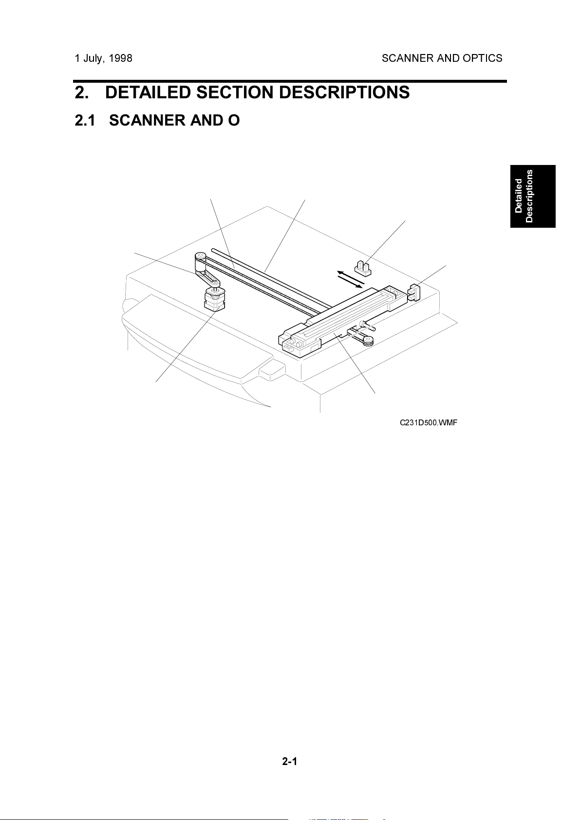
2.1 SCANNER AND OPTICS
2.1.1 BOOK SCANNER OVERVIEW
[D]
[C]
[A]
The scanner motor [A] drives the scanner [B] through the timing belt [C] and drive
wire [D]. The shaft [E] guides scanner movement in the sub-scan direction. Inside
the scanner [B] are a contact image sensor (containing a sensor element and
xenon lamp) and a xenon lamp driver.
[E]
[I]
[H]
[B]
C231D500.WMF
Detailed
Descriptions
The scanner [B] consists of a contact image sensor and a xenon lamp driver.
The scanner home position sensor [H] allows the scanner return to the same
position after scanning.
The platen cover switch [I] detects the cover status.
2-1
Page 22
SCANNER AND OPTICS 1 July, 1998
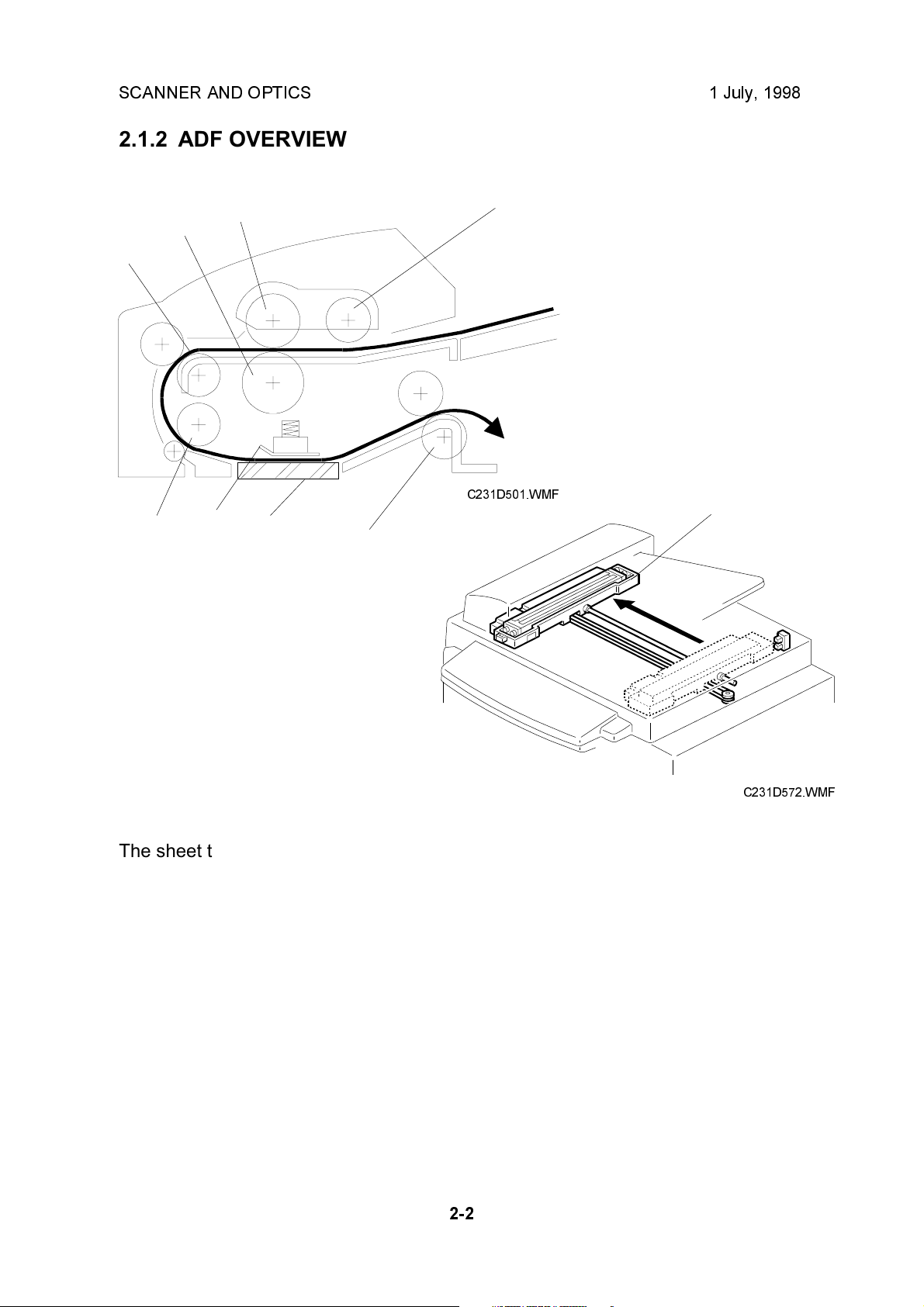
2.1.2 ADF OVERVIEW
[D]
[E]
[C]
[F]
[B]
[G]
[A]
C231D501.WMF
[I]
[H]
C231D572.WMF
The sheet through-type ADF feeds the document from the top of the document
stack.
The pick-up roller [A] and feed roller [B] feed the original into the scanner, and the
separation roller [C] helps to feed one sheet at a time. Then, the R0 [D], R1 [E],
and R2 [H] rollers feed the document through the scanner.
During scanning, the scanner [I] moves to the scanning position under the
exposure glass [G]. The shading plate [F] secures the document at the scan line,
ensuring the document is within the image sensor's range of focus.
After scanning, the ADF feeds out the document onto the platen cover, and the
scanner moves back to its home position.
2-2
Page 23
1 July, 1998 SCANNER AND OPTICS
[B]
[A]
C231D502.WMF
Detailed
Descriptions
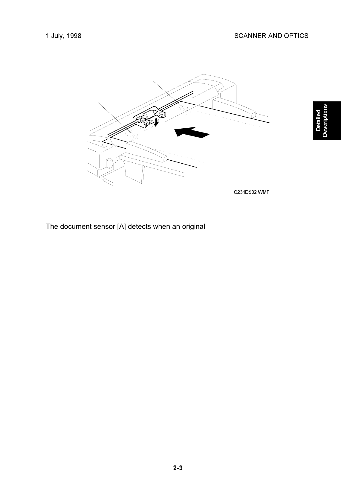
The document sensor [A] detects when an original is placed in the ADF. The
sensor [B] is not used in this unit. The ADF is a common part which is used in other
models.
2-3
Page 24
SCANNER AND OPTICS 1 July, 1998
2.1.3 CONTACT IMAGE SENSOR
[D]
[A]
[C]
[B]
[F]
[E]
C231D503.WMF
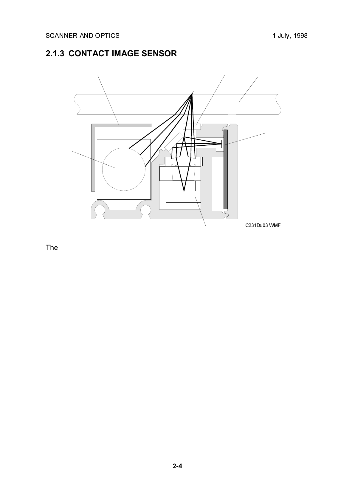
The contact image sensor (CIS) assembly [A] consists of the exposure glass [B],
roof mirror lens array [C], xenon lamp [D], and the image sensor [E].
The CIS moves under the exposure glass when scanning a book original, or stays
at the ADF scan line when scanning a sheet original using the ADF.
The image sensor is a row of 4096 photosensitive elements (B4 width x 16
dots/mm). The roof mirror lens array focuses the light reflected from the document
onto the image sensor.
Due to the short optical path of a CIS unit, the focal depth is much shorter than in a
CCD type scanner. Because of this, two springs push the CIS against the exposure
glass [F], to keep the distance between the CIS and the original constant. In book
scanning mode, if the original is out of the CIS focal range, however, the scanned
image may be darkened.
NOTE:
Due to the characteristics of the CIS, shadows of a paste-up original tend
to appear on copies. To counter this, press a key on the operation panel to
use the paste shadow erase mode.
The strength of the paste shadow erase level can be increased with SP no.
28.
2-4
Page 25
1 July, 1998 SCANNER AND OPTICS
2.1.4 DRIVE MECHANISM
Book Scanner
[D]
[E]
[C]
[A]
[B]
[G]
Detailed
Descriptions
[F]
C231D504.WMF
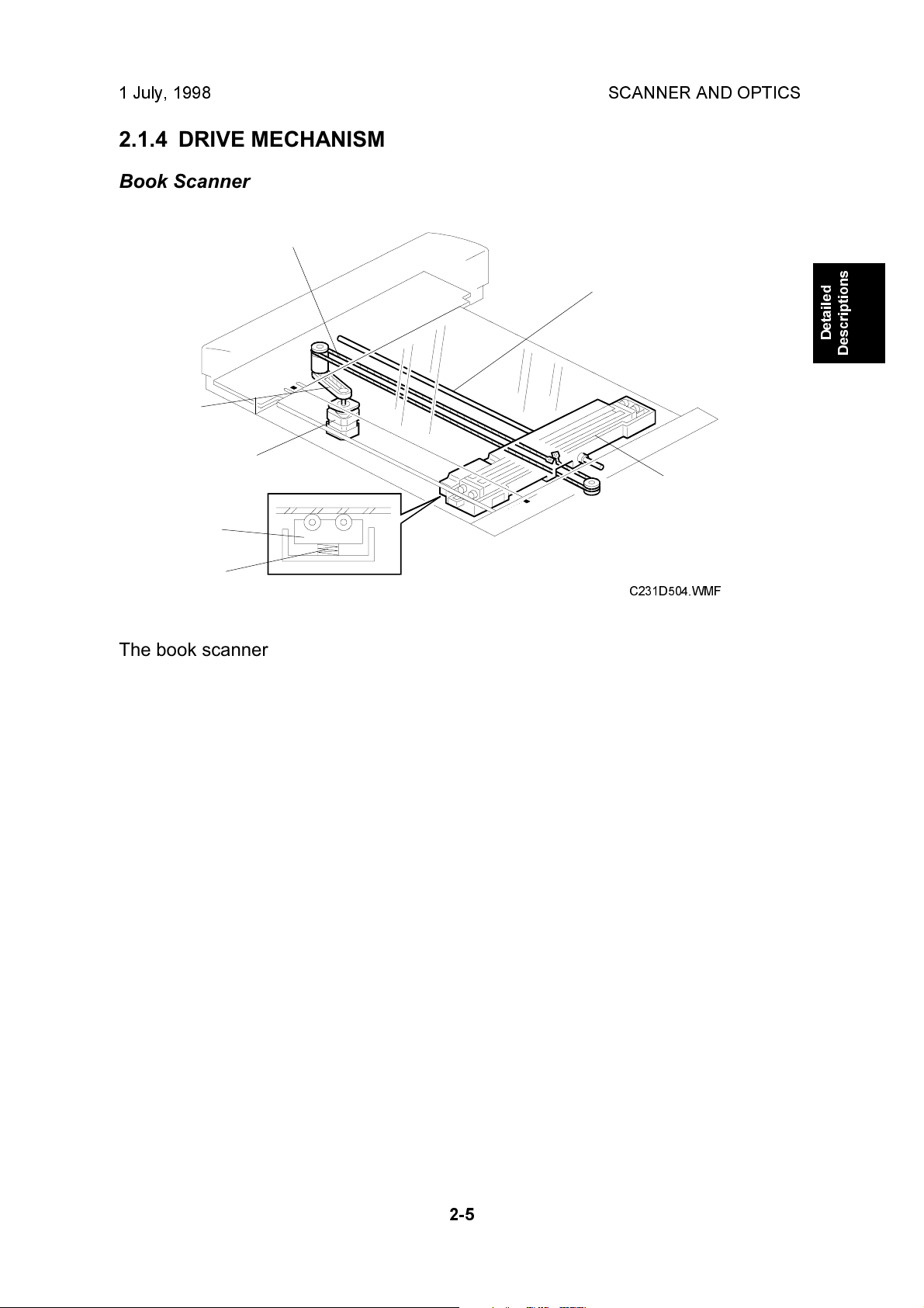
The book scanner motor [A] drives the scanner [B] via a timing belt [C] and drive
wire [D]. The scanner moves along the guide shaft [E].
The springs [F] apply pressure to the contact image sensor [G] to ensure that the
distance from the image sensor to the exposure glass surface remains constant
during scanning.
2-5
Page 26
SCANNER AND OPTICS 1 July, 1998
ADF
[A]
[C]
[D]
[B]
[E]
C231D505.WMF
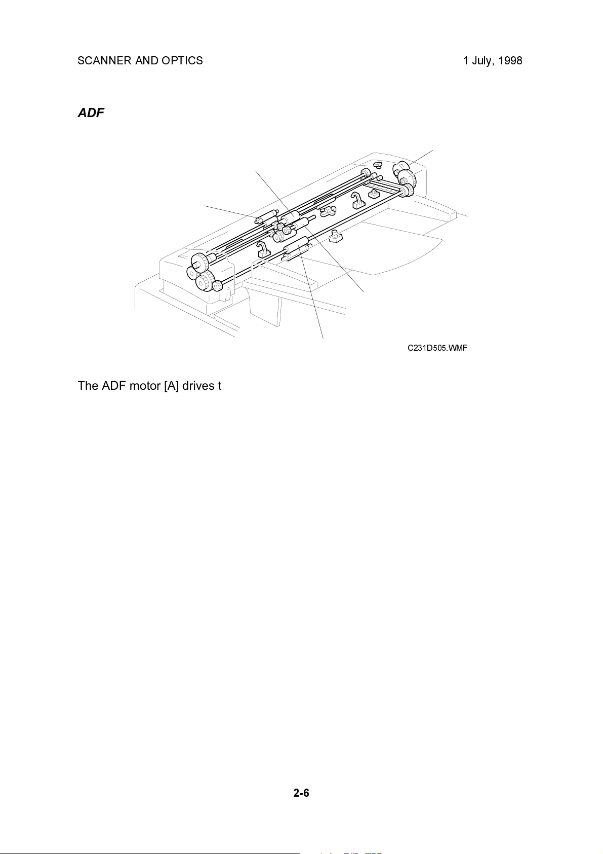
The ADF motor [A] drives the pick-up roller [B], the feed roller [C], the R0 roller [D],
the R1 roller (this is obscured in the diagram), and the R2 roller [E].
2-6
Page 27
1 July, 1998 SCANNER AND OPTICS
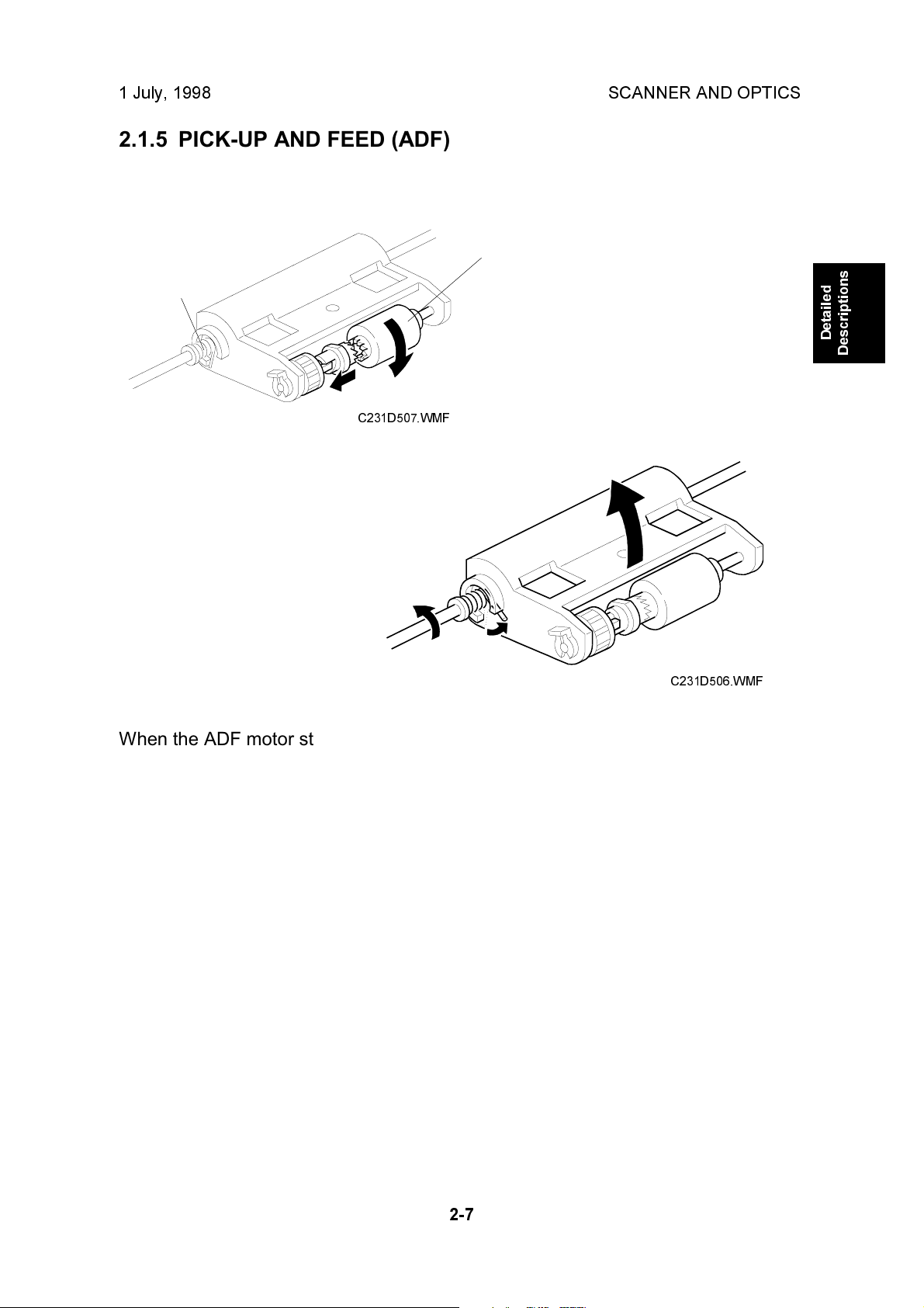
2.1.5 PICK-UP AND FEED (ADF)
[B]
[A]
C231D507.WMF
Detailed
Descriptions
C231D506.WMF
When the ADF motor starts, the mechanical clutch [A] engages and lowers the
pick-up roller [B] into contact with the document. Then the machine begins feeding
the original stack, beginning with the top page. After the last page is scanned, the
ADF motor reverses briefly to raise the pick-up roller back to the standby position.
2-7
Page 28
SCANNER AND OPTICS 1 July, 1998
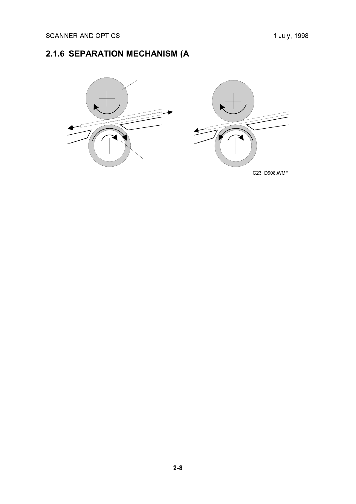
2.1.6 SEPARATION MECHANISM (ADF)
[A]
[B]
C231D508.WMF
The feed roller [A] and the separation roller [B] prevent more than one sheet of
paper from feeding into the scanner at the same time.
When the feed roller feeds a sheet of paper, both the feed and the separation
rollers rotate in the feed-in direction. However, if two or more sheets are between
these rollers, the separation roller rotates in the feed-out direction to prevent the
lower sheet from being fed into the scanner.
2-8
Page 29
1 July, 1998 SCANNER AND OPTICS
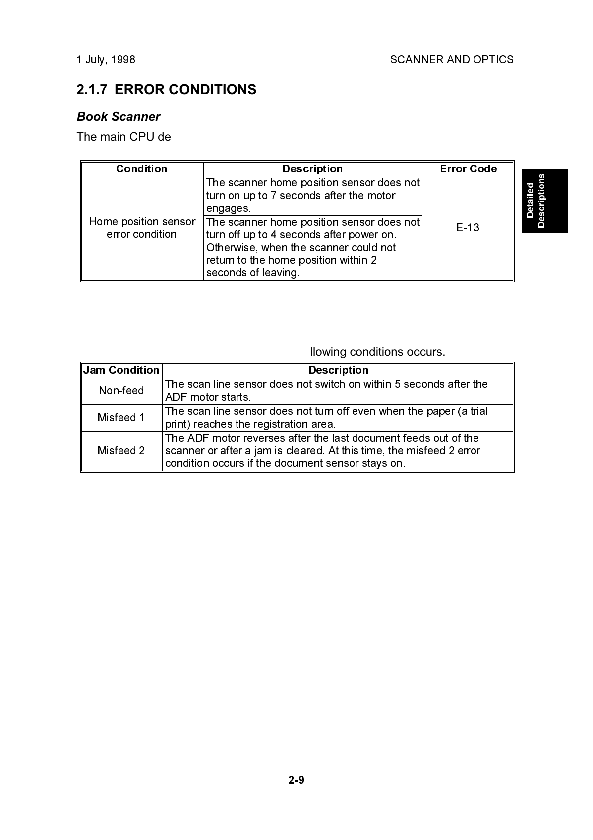
2.1.7 ERROR CONDITIONS
Book Scanner
The main CPU detects an error (error code E-13 is displayed) if either of the
following conditions occurs.
Condition Description Error Code
The scanner home position sensor does not
turn on up to 7 seconds after the motor
engages.
Home position sensor
error condition
ADF
The scanner home position sensor does not
turn off up to 4 seconds after power on.
Otherwise, when the scanner could not
return to the home position within 2
seconds of leaving.
E-13
Detailed
Descriptions
"Paper feed jam" is displayed if any of the following conditions occurs.
Jam Condition Description
Non-feed
Misfeed 1
Misfeed 2
The scan line sensor does not switch on within 5 seconds after the
ADF motor starts.
The scan line sensor does not turn off even when the paper (a trial
print) reaches the registration area.
The ADF motor reverses after the last document feeds out of the
scanner or after a jam is cleared. At this time, the misfeed 2 error
condition occurs if the document sensor stays on.
2-9
Page 30
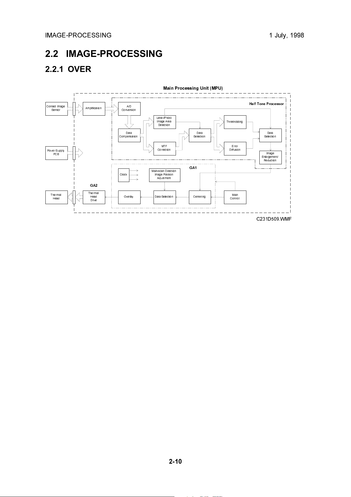
IMAGE-PROCESSING 1 July, 1998
2.2 IMAGE-PROCESSING
2.2.1 OVERVIEW
Main Processing Unit (MPU)
Error
Main
Half Tone Processor
Data
Selection
Image
Enlargement/
Reduction
Contact Image
Sensor
Power Supply
PCB
Thermal
Head
Amplification
GA2
Thermal
Head
Drive
A/D
Conversion
Data
Compensation
Clock
Overlay
Letter/Photo
Image Area
Detection
MTF
Correction
Main-scan Direction
Image Position
Adjustment
Data Selection
GA1
Data
Selection
Centering
Thresholding
Diffusion
Control
C231D509.WMF
This model uses a contact image sensor (CIS) instead of a CCD. It removes the
necessity for the complicated adjustments needed for a CCD scanner.
There are three main chips on the main processing unit (MPU) as shown. The
halftone processor chip enables the use of Letter/Photo mode in addition to Letter
and Photo modes. In Letter/Photo and Photo modes, error diffusion processing
produces better copy quality halftone images.
The halftone processor also includes the A/D conversion function, as well as the
image processing functions. The thermal head drive function is built into a chip
(GA2) on the MPU.
2-10
Page 31

1 July, 1998 IMAGE-PROCESSING
2.2.2 A/D CONVERSION PROCESSING
The analog signal from the contact image sensor is converted into a digital signal
that represents 64 grayscale steps. This process is carried out in the halftone
processing chip in the MPU.
Shading Distortion Correction
The image data from one main scan line does not exactly represent the line from
the original image, because of the following reasons:
1) Loss of brightness towards the ends of the exposure lamp.
2) Variations in sensitivity among elements of the contact image sensor
3) Distortions of the light path
Detailed
Descriptions
CIS
CIS
C231D510.WMF
Such distortions in the image data are corrected when they are converted into
digital data.
Before scanning the document, the scanner reads the white plate on the back of
the original scale. The output of each contact image sensor element is changed to
a 6-bit digital value and stored in the shading distortion memory.
To change the analog shading distortion signals to digital data, a scale of 64 steps
is made between the whitest level when the white plate is scanned and 50% of the
whitest level. Using this scale, the analog signal is changed to 6-bit digital data.
While an original is scanned, the 6-bit shading distortion value for each pixel is sent
in series from memory to the D/A converter, synchronizing with the image signal
being sent to the A/D converter. The D/A converter changes the distortion value to
an electrical current. The current is converted to the voltage to be used as high
reference data for A/D conversion. In this way, the high reference voltage for A/D
conversion is changed sequentially for each pixel depending on the shading
distortion data for that pixel.
2-11
Page 32

IMAGE-PROCESSING 1 July, 1998
Original Background Correction
When an original is scanned, the whitest level of the original background is stored,
and that level is used as the white peak level for A/D conversion. The grayscale is
made based on the white peak level of the original. As a result, dark background
does not appear on the printout.
If the original background correction is disabled, the whitest level when the white
plate is scanned is used for the high reference voltage.
C231D512.WMF
Peak Hold
The peak hold circuit holds the voltage for the white peak level. Before scanning an
original, it holds the white peak voltage from the white plate to make shading
distortion data. When the original is scanned, it stores the white peak level of the
original for the original background correction.
NOTE:
The white peak level is checked 5 mm from the leading edge of the original
set on the exposure glass (and from the central 147-mm width). If the
original leading edge is not flush with the original scale and the platen
cover stays open, insufficient voltage will be input as the white peak level.
If insufficient voltage is detected, a fixed voltage is used as the white peak
level to avoid a faint image copy.
2-12
Page 33

1 July, 1998 IMAGE-PROCESSING
2.2.3 BINARY PROCESSING
In the halftone-processing chip, the 6-bit digital signal data is generated in the A/D
conversion circuit and is sent to the binary processing circuit. At that time the data
is inverted to match the binary processing circuit. Therefore, the white peak level
becomes 0, and the black level becomes 63.
In the binary processing circuit, the 6-bit data is converted into 1-bit data for black
or white pixels. The binary processing for the letter and photo is different, as
follows:
Letter Mode, Letter areas in Letter/Photo Mode: MTF (Modulation Transfer
Function) Correction
Photo Mode, Photo areas in Letter/Photo Mode: Error Diffusion Processing
Data Compensation Processing
In this process, the 6-bit data are converted based on a compensation curve
(gamma curve) which corresponds to selected image settings. For example, if a
darker image is selected, a compensation curve, which converts each pixel value
to a higher number, is selected. The output data is still 6-bit.
Detailed
Descriptions
Input
6-bit data from
the A/D conversion
PCB
Gamma curve
selection signal
Data
Compensation
Circuit
Output
6-bit data
C231D514.WMF
2-13
C231D515.WMF
Page 34

IMAGE-PROCESSING 1 July, 1998
MTF Correction
When the original image is converted to electrical signals by the contact image
sensor, the contrast is reduced. This is because neighboring black and white parts
of the image influence each other. This symptom is typical when the width and
spacing between black and white areas are narrow. MTF correction counters this
symptom and emphasizes image detail. The value of a target pixel is modified
depending on the value of surrounding pixels. The modified data are compared
with a threshold level. This determines if the pixel is to be black or white.
After the MTF correction is done, the corrected data are compared with the black or
white threshold level. If a pixel value is above the threshold level, it is set to black.
If the pixel value is equal or below the threshold level, it is set to white. The
threshold level depends on the selected density setting.
Image Density
Setting
Lighter 28 35
Normal 35 40
Darker 1 38 42
Darker 2 42 44
Threshold Level for Line
Mode
Threshold Level for Line
Areas in Line/Photo Mode
Binary Processing in Letter/Photo Mode
In the Letter/Photo mode, the machine checks each pixel of the original to see if
the pixel is in a letter area or in a photo area. To distinguish letter and photo areas,
the CPU does the calculation on the 6-bit pixel data.
If the CPU recognizes that pixel is in a letter area of the image and uses the MTF
process to convert the 6-bit value to 1-bit.
If the CPU recognizes that pixel is in a photo area of the image, the pixel is
converted to 1-bit using error diffusion.
To emphasize characters in a photo original when using Letter/Photo mode, a data
compensation curve (g curve) is used to make a darker image.
2-14
Page 35

1 July, 1998 IMAGE-PROCESSING
Error Diffusion
Error diffusion is used to reproduce halftone images in photo mode.
Before a 6-bit image signal is converted into a single-bit signal based on the
threshold level, there is a difference between the image signal value and the
complete black value (63 for a 6-bit signal) or white value (0). With the error
diffusion process, the difference is distributed among the surrounding pixels. (The
MTF process simply erases these differences.)
When considering error diffusion in one dimension only (across the page), the 6-bit
data shown in the example below produces white and black data output as shown
below. In practice, this one-dimensional error diffusion is done in all directions on
each pixel (across the page, down the page, etc.).
Image data from one scan line
711132130384144
Detailed
Descriptions
C231D518.WMF
In each dimension, the difference between the pixel value and the nearest extreme
(0 or 63) is transferred to the next pixel. The 1st pixel in the row becomes either
black or white, whichever is closest. Then, in the example above, the difference
between 7 and 0 is added to the 2nd pixel. The value of the 2nd pixel, which is now
18, is then added to the 3rd pixel. The 4th pixel becomes 52, which is closer to 63
than 0. In such cases, the difference is subtracted (not added) to get the next pixel
value. In this example, the difference is 63-52=11, and the next pixel value (30-11)
becomes 19.
2-15
Page 36

IMAGE-PROCESSING 1 July, 1998
2.2.4 MAIN SCAN MAGNIFICATION
Scanned Data
Points
Calculated Data
Points
Reduced Image
Data Points
Scanned Data
Points
Calculated Data
Points
Reduced Image
Data Points
Changing the original transport speed does reduction and enlargement in the subscanning direction. Reduction and enlargement in the main scanning direction is
handled by the magnification and image shift processing circuits.
C231D520.WMF
Pixels for scanning and master making are generated at fixed intervals (the contact
image sensor and thermal head element intervals). The image is scanned at the
contact image sensor element interval. If pixels on the master are made at the
same interval (by the thermal head elements) then the master image is the same
size as the original.
When actual pixels are divided in accordance with a magnification ratio, the
magnification processor calculates the imaginary points values that would
correspond to new pixels. The proper value for each imaginary point is calculated
based on the image data of the surrounding pixel values.
- 80 % Reduction -
For example, the contact image sensor scans data for 10 pixels in a main scan
line. Those data are compressed into data for 8 pixels by the magnification
processor. As a result, the image is reduced to 80 %.
- 140 % Enlargement -
Data for 10 pixels of a main scan line are expanded into data for 14 pixels. As a
result the image is enlarged with a 140 % magnification ratio.
2-16
Page 37

1 July, 1998 IMAGE-PROCESSING
2.2.5 IMAGE POSITION ADJUSTMENT IN THE MAIN SCAN DIRECTION
To adjust the image position of the original across the printout, the image can be
shifted ± 1.9 mm in the main scan direction using SP mode No. 31 (platen mode)
or No. 37 (ADF mode).
The image shift in the main scan direction is done by changing the relationship
between the position of the image data on the CIS and on the thermal head. Data
for one main scan line are stored in a line memory. When the data is output from
memory, the output timing is changed to shift the image.
CIS Center
3072
3072
3072
Data from CIS
After A/D Conversion
Data from
Thermal Head Driver,
No Image Shift
Data from
Thermal Head Driver,
Image Shift x mm
(SP 31 or 37)
0
Thermal Head
Center
0
xmm
0
Thermal Head
Center
Detailed
Descriptions
C231D521.WMF
2.2.6 PASTE SHADOW ERASE MODE
Due to the characteristics of the contact image sensor, shadows of a paste-up
original tend to appear on copies. To counter this, the paste shadow erase mode
can be used by pressing a key on the operation panel.
When this mode is selected, the black or white threshold level is slightly lowered.
At the same time, the emphasis in the sub-scan direction in the MTF correction
process is weakened to make the shadows inconspicuous.
The strength of the paste shadow erase level can be increased with SP No. 28.
2-17
Page 38

IMAGE-PROCESSING 1 July, 1998
2.2.7 THERMAL HEAD
Specifications
· Length 260.2 mm
· Number of thermal head elements 3072 dots
· Density of thermal head elements 300 DPI
· Applied voltage Approximately 21 volts
Thermal Head Control
The thermal head has heating elements at a density of 300 dpi. The thermal
heating elements melt the over-coating and polyester film layers of the master,
according to the image signal for each pixel.
The power supply unit applies power (VHD) to the thermal heating elements. The
power source varies from one head to another since the average resistance of
each element varies. Therefore, when the thermal head or power supply unit is
replaced, it is necessary to readjust the applied voltage with particular values for
each thermal head.
Thermal Head Protection
The thermistor on the thermal head provides thermal head protection, preventing
the thermal head from overheating when processing a solid image. The CPU
detects any abnormal condition when the Start key is pressed, and displays an SC
code on the operation panel as follows:
SC Code Conditions
E-04
E-09
E - 10 When the pulse width that controls the
Over 54°C
Under - 20°C (Normally, this indicates that
the thermistor has become open, or a
related connector is disconnected.)
thermal head energy becomes abnormal,
master making stops and this SC lights.
Detecting
Component
Thermistor
Thermistor
MPU
2-18
Page 39

1 July, 1998 IMAGE-PROCESSING
Remarks for Handling the Thermal Head
The following remarks must be noted when servicing:
·
·
Do not touch the surface
with bare hands. If you
touch it, clean the surface
with alcohol.
·
Do not damage the
heating elements.
Platen
Master
Remove any foreign materials on
the platen roller.
·
Remove foreign materials.
·
Do not touch the surface of the
master film with bare hands.
·
Do not touch the terminals of
the connectors with bare
hands to prevent damage from
static electricity.
Detailed
Descriptions
MPU
Thermal Head
·
Connect and disconnect the connectors
carefully. Keep them horizontal. Also,
make sure that they are reconnected
firmly.
·
Adjust the applied voltage to the
particular value for the thermal head.
Connector
PSU
- Other Remarks -
Avoid using the machine under humid conditions. Moisture tends to condense on
the thermal head, causing heating element damage.
2-19
Page 40

MASTER EJECT 1 July, 1998
2.3 MASTER EJECT
2.3.1 OVERALL
[B]
[A]
C231D531.WMF
[C]
[B]
[C]
C231D530.WMF
At the end of the printing cycle, the used master remains wrapped around the drum
to prevent the ink on the drum surface from drying. When the Master Making key is
pressed to make a new master, the used master is removed from the drum.
The machine ensures that the drum is at the master eject position and a master is
on the drum by checking the drum master sensor. The master clamper [A] then
opens to eject the master. If there is no master on the drum, the machine skips the
master eject operation and proceeds to the master making process.
The master eject rollers [B] turn for 0.6 seconds and pick up the master's leading
edge. After closing the master clamper, the drum starts rotating at the slowest
speed (30 rpm). At the same time the master eject rollers turn and feed the used
master into the master eject box [C].
When the drum stops at the master feed position after one and a half turns, the
pressure plate drive motor starts turning to compress the used master into the
master eject box.
2-20
Page 41

1 July, 1998 MASTER EJECT
2.3.2 MASTER CLAMPER OPEN MECHANISM
[B]
[A]
[H]
[D]
[I]
[G]
[C]
[F]
[E]
[J]
C231D557.WMF
The master eject position sensor [A] ensures that the drum is positioned at the
master eject position when the Start key is pressed.
The master clamper has a magnetic plate [C] to secure the master's leading edge
in the clamper. The clamper is fixed to the clamper shaft [D], which has a lever [E]
at the rear side.
Detailed
Descriptions
The clamper motor [F] drives the moving link [G] and pushes up the clamper lever
[E]. (The link position, the clamper open and close positions, are maintained by the
clamper open sensor [H] and clamper close sensor [I].)
The master clamper then lifts the master eject arm [J] to release the master's
leading edge from the clamper.
Drum Position Lock Mechanism
When the clamper motor [F] opens the clamper at the master eject position, the
drum guide [B] moves and engages the pin on the rear flange of the drum.
The drum guide is moved by the same mechanism that drives the moving link [G].
This means that the drum guide catches the drum at the master eject position while
the master clamper is being opened.
When the clamper motor turns on again to close the master clamper, the drum
guide also disengages the pin and the drum can now turn.
2-21
Page 42

MASTER EJECT 1 July, 1998
2.3.3 MASTER EJECT ROLLER MECHANISM
[B]
[C]
[A]
C231D532.WMF
The master eject rollers are driven by the master eject motor [A] through idle gears.
The upper eject roller [B] has paddles to assure the master pick-up.
When the master clamper is opened and the master's leading edge is released
from the master clamper, the master eject motor turns on for 0.6 seconds to pick
up the leading edge of the master.
When the master eject motor is turned off, the clamper motor reverses to close the
master clamper.
The drum then starts turning at the slowest speed (30 rpm). At the same time, the
master eject rollers turn again to feed the master into the master eject box.
After one turn of the drum, the master eject motor stops. The drum turns for an
additional half turn, stopping 109 encoder pulses after the feed start timing sensor
is actuated (this means that the drum is at the master feed position).
The master eject sensor [C] detects master eject jams.
2-22
Page 43

1 July, 1998 MASTER EJECT
2.3.4 PRESSURE PLATE MECHANISM
[A]
[E]
[D]
[B]
[C]
Detailed
Descriptions
[C]
[B]
[F]
C231D533.WMF
The pressure plate motor [A] drives the pressure plate through the drive arm [B]
and the pressure springs [C].
When the master has been ejected into the master eject box, the pressure plate
motor turns until the actuator on the pressure plate [E] actuates the pressure plate
limit sensor [D]. When the limit sensor is actuated, the motor stops. When master
making and cutting are completed, the motor turns in the reverse direction to return
the pressure plate to the home position. When the pressure plate home position
sensor [F] is actuated, the motor stops.
If the pressure plate limit sensor is not actuated within 2.8 seconds after the
pressure plate motor is activated, the machine determines that the eject box is full
and that the pressure plate cannot travel any more. In this case, the machine
determines that the complete master has been fed into the box and stops the
motor (after returning the pressure plate to the home position). The Empty Master
Eject Box indicator lights when the drum returns to the home position at the end of
the next master making process.
2-23
Page 44

MASTER FEED 1 July, 1998
2.4 MASTER FEED
2.4.1 OVERALL
[A]
[C]
[B]
[E]
[D]
C231D534.WMF
The master is fed by the platen roller [A] while the thermal head [B] develops the
image on it. When the drum is at the master feed position and the master clamper
is opened, the tension roller [C] is moved away by the master clamper so that the
master's leading edge can be fed to the master clamper [D]. The leading edge of
the master is clamped by the master clamper, and the master is wrapped around
the drum and cut by the cutter [E] to the desired length.
This model uses a new master setting mechanism. This eliminates need for the
operator to manually cut the master, unlike the other models.
2-24
Page 45

1 July, 1998 MASTER FEED
2.4.2 MASTER FEED MECHANISM
[B]
Detailed
Descriptions
C231D536.WMF
[C]
[D]
[A]
C231D535.WMF
A stepper motor (the master feed motor [A]) drives the platen roller [B]. The thermal
head is pressed against the platen roller by the pressure springs. The pressure is
applied when the master set cover, which includes the platen roller, is closed.
After the master is ejected, the drum stops at the master feed position and the
master clamper opens, ready to clamp the new master.
The leading edge of the master is stopped on the guide plate after the last master
cutting operation or after a new master roll has been installed. The master is then
fed for 52.4 mm and stopped briefly to synchronize with original feed. The master is
fed for a further 67.5 mm before the master clamper is closed. Since the clamper
closes after the master's leading edge reaches the clamper, a buckle [C] is made in
the master above the master feed guide. This buckle absorbs the shocks from the
master clamping operation.
The drum then turns intermittently in the slowest mode (30 rpm) to wrap the master
around the drum. The intermittent rotation keeps a buckle in the master above the
master feed guide to absorb shocks from the wrapping operation. The tension roller
[D] is pressed against the guide plate to keep the master under tension during the
master wrapping operation.
2-25
Page 46

MASTER FEED 1 July, 1998
2.4.3 MASTER CLAMPER OPERATION AND TENSION ROLLER RELEASE MECHANISM
[B]
[A]
[D]
[C]
[E]
C231D537.WMF
When the master has been ejected, the drum is stopped at the master feed
position. At this time, the clamper motor [A] drives the moving link [B] to open the
master clamper [C].
The tension roller [D] is normally pressed against the master feed guide plate to
apply tension to the master during the master wrapping operation. When the
clamper opens, the clamper pushes the tension roller arms [E] and moves the
tension roller away from the guide plate to allow the master to be fed into the
master clamper.
To close the master clamper, the clamper motor reverses.
NOTE:
The clamper open and close sensors maintain the link [B] position. Refer to
the Master Eject section for details.
2-26
Page 47

1 July, 1998 MASTER FEED
2.4.4 CUTTER MECHANISM
Detailed
Descriptions
[E]
[A]
[B]
[C]
C231D573.WMF
[D]
After the master making process finishes, the master feed motor turns off and the
cutter starts running to cut the master to the desired length.
The cutter motor [D] drives the screw shaft [A], moving the cutter holder [C]
backwards and forwards.
There are two cutter blades [B] in the holder. While the cutter holder [C] travels
towards the rear (the non-operation side of the machine), they cut the master. The
cuter motor keeps turning in one direction. However the cutter holder returns to the
home position when it reaches the rear end of the cutter unit because of the two
different spirals threaded on the screw shaft [A].
When the cutter holder reaches the home position, the holder activates the cutter
home position sensor [E] and the motor stops.
After the master cut operation, the drum starts turning again to wrap the remaining
part of the master around the drum. The leading edge of the master that was cut
remains at the cutting position, ready to make the next master.
2-27
Page 48

DRUM 1 July, 1998
2.5 DRUM
2.5.1 OVERALL
[A]
[B]
[C]
[D]
[E]
The drum consists of a metal screen [A] and a cloth screen [B].
The ink pump, which is installed inside the drum, supplies ink from the ink cartridge
into the drum through the drum shaft [C]. Ink is then evenly spread on the screens
by the ink [D] and doctor [E] rollers. Ink passes to the paper through the holes in
the master [F], which were made by the thermal head.
The drum is driven by the main motor and turns only clockwise (as viewed from the
operator side). The motor speed and the drum stop positions are controlled by
monitoring the motor encoder.
C231D538.WMF
[F]
2-28
Page 49

1 July, 1998 DRUM
2.5.2 DRUM DRIVE MECHANISM
[E]
[F]
Detailed
Descriptions
[D]
[A]
[C]
[B]
C231D539.WMF
The drum is driven by the main motor (a dc motor) through a timing belt [A] and
gears [B]. The main motor has an encoder which sends pulses to the main motor
control board. The CPU on the board monitors the pulses and controls the drum
speed and stop positions.
The drum has two stop positions: the master eject (drum home) position and the
master feed position. These stop positions are determined by checking the feed
start timing sensor [C]. The CPU starts counting the main motor encoder pulses
when the feed start timing sensor is actuated.
When the drum is stopped at the master eject position, the master eject position
sensor [D] is actuated. When the master eject operation is started, the CPU
confirms that the drum is at the master eject position by checking this sensor.
There are other two sensors that check the drum position. The paper exit timing
sensor [E] and 2nd feed timing sensor [F] are used to send the CPU (on the MPU)
the paper jam detection timing of the paper exit and the registration area. (The
actual jam checking is done by the paper exit sensor and registration sensor.)
2-29
Page 50

DRUM 1 July, 1998
2.5.3 INK SUPPLY MECHANISM
[A]
[C]
[F]
[D]
[B]
[E]
C231D540.WMF
Ink is supplied from the ink cartridge to the ink roller [B] by a pump [C]. The ink
pump is driven by the ink supply motor (a dc motor) [D]. There is a pin on the pump
drive gear [E] which is coupled with the pin holder [F] on the pump piston shaft.
This mechanism converts the gear rotation into piston motion.
Ink drops through the holes in the drum shaft [A] onto the ink roller [B].
NOTE:
There are 4 holes in the shaft for the B4 size drum models, and two holes
for the Legal and A4 drum versions.
2-30
Page 51

1 July, 1998 DRUM
2.5.4 INK ROLLER MECHANISM
[C]
[D]
Detailed
Descriptions
[A]
[B]
[E]
C231D541.WMF
[F]
The ink roller [A] and the doctor roller [B] are driven by the gear [C] on the drum
shaft. Ink on the ink roller is squeezed by the doctor roller to produce an even
thickness of ink on the ink roller. The ink roller drive gear [D] has a one-way clutch
to prevent the ink roller from being turned in the reverse direction when the drum is
manually turned in the reverse direction.
The ink roller does not touch the screen [E] when the machine is not printing.
However, during the printing process, the ink on the ink roller is applied to the
paper through the holes in the screens and master. This happens when the press
roller [F] underneath the drum moves up to press the drum screen and the master
against the ink roller.
2-31
Page 52

DRUM 1 July, 1998
2.5.5 INK SUPPLY CONTROL
[C]
[B]
[A]
[D]
C231D542.WMF
The ink detecting pins [A] work like the electrode of a capacitor and detect the
capacitance between the detection pins and the ink [B] and doctor [C] rollers. This
capacitance is different when the ink level is high and the pins touch ink, compared
to when the ink level is low and the pins do not touch ink. By detecting the
capacitance, the ink supply motor is controlled to keep the ink level normal.
If the pins detect an insufficient amount of ink after activating the ink pump motor
for 40 seconds, a "no ink condition" is detected. The add ink indicator on the
operation panel will light.
NOTE:
There is an ink supply mode, which is useful when installing a new drum.
When the Economy Mode key is pressed while holding down the 0 key,
the drum turns 40 rotations, to supply ink inside the drum.
The ink roller blades [D] on both ends of the ink roller scrape off the built-up ink on
the ends of the ink roller.
2-32
Page 53

1 July, 1998 DRUM
2.5.6 DETECTION OF MASTERS ON THE DRUM
[A]
[B]
Detailed
Descriptions
C231D571.WMF
The drum master sensor [B] detects whether a master is on the drum.
When there is a master on the drum, the black patch [A] is covered and the sensor
detects the light reflected from the master. Printing starts when the start key is
pressed. (If an original is set, the master ejecting starts before making a new
master.)
When there is no master on the drum, the black patch [A] is exposed. The black
patch does not reflect light back to the sensor. Because of this, the master eject
process can be skipped when a new master is made.
2-33
Page 54

PAPER FEED 1 July, 1998
2.6 PAPER FEED
2.6.1 OVERALL
[B]
[D]
[C]
C231D543.WMF
The top sheet of the paper on the paper table is first fed by the pick-up roller [A].
Then, it is separated by the paper feed roller [B] and the friction pad [C], and
transported to the registration rollers [D]. The upper and lower registration rollers
transport the sheet to the drum.
[A]
The paper feed roller is driven by the main motor, and an independent stepper
motor is used to control the registration roller. The registration roller synchronizes
the paper feed timing with the master on the drum. The registration roller starts
rotating after the paper has come into contact with the rollers and has been
aligned.
2-34
Page 55

1 July, 1998 PAPER FEED
2.6.2 PAPER FEED MECHANISM
[D]
[B]
[A]
[E]
[C]
C231D556.WMF
The pick-up roller [A] and paper feed roller [B] are driven by the main motor [C]
through gears and a timing belt.
Detailed
Descriptions
During the printing cycle, when the feed start timing sensor [D] is actuated by the
actuator on the drum, the paper feed clutch [E] is energized to transmit the main
motor rotation to the paper feed roller shaft. The top sheet of the paper is
separated from the paper stack by the friction between the roller and the friction
pad [F], and transported to the registration roller.
A one-way clutch is installed in the paper feed roller so that after the
electromagnetic clutch is de-energized, it does not disturb the paper transportation.
2-35
Page 56

PAPER FEED 1 July, 1998
2.6.3 PAPER FEED/SEPARATION PRESSURE ADJUSTMENT
MECHANISM
[B]
[A]
C231D554.WMF
[E]
[D]
[C]
C231D558.WMF
The paper feed roller pressure can be changed by the operator by changing the
position of the pressure adjustment lever [A]. Normally the lever should be in the
lower position. If the thick paper (heavier than 127.9 g/m2 or 34 lb) is used or paper
feed jams frequently occur, the lever should be raised to increase the pressure.
An additional fine adjustment can be done by a technician by changing the position
of the feed pressure adjustment plate [B].
If no feed or multi-sheet feed problems still occur, the paper separation pressure
can also be adjusted. (This should be done by a technician.)
By loosening then moving up or down the screw [C], the spring [D], which applies
pressure to the friction pad block [E], moves up or down.
NOTE:
The default position of the screw [C] is the lower-most position.
2-36
Page 57

1 July, 1998 PAPER FEED
2.6.4 REGISTRATION ROLLER MECHANISM
[B]
[A]
Detailed
Descriptions
C231D544.WMF
Registration Roller Drive
The lower registration roller [A] is driven by a stepper motor [B] (the registration
motor). The CPU controls the registration roller start timing to synchronize the
printing paper with the image on the master on the drum.
The stepper motor rotation speed depends on the selected printing speed. By
pressing the image position keys on the operation panel, the registration motor
start timing is changed.
After the printing paper is caught between the drum and the press roller, the
stepper motor stops.
2-37
Page 58

PAPER FEED 1 July, 1998
[B]
[C]
[D]
C231D545.WMF
[A]
Registration Roller Up/Down Mechanism
After the printing paper is caught between the drum and the press roller, the upper
registration roller is released from the lower registration roller. This is to prevent
interference from the registration rollers while the paper is transported by the drum
and the press roller.
When high point of the cam [A] on the drum drive gear reaches the cam follower
[B], the shaft [C] rotates clockwise (as seen from the operation side) to release the
upper registration roller [D] from the lower registration roller.
2-38
Page 59

1 July, 1998 PAPER FEED
2.6.5 PRINTING PRESSURE MECHANISM
[I]
[F]
[D]
[E]
[A]
[B]
Detailed
Descriptions
[H]
[C]
[A]
[E]
[G]
[ I ]
C231D546.WMF
[F]
While the machine is not in the printing cycle, the printing pressure release
solenoids [A] stay off and the stoppers [B] lock the brackets [C] to keep the press
roller [D] away from the drum.
When the 1st sheet of paper is fed, the solenoid is energized but the brackets are
still locked by the stoppers due to strong tension from the springs [E]. When the
high points of the cams [F] on the front and rear drum flanges reach the cam
followers [G] on both sides of the press roller shaft, a small clearance is made
between the stoppers and the brackets.
There is one solenoid each on the operation side and non-operation side. The two
solenoid plungers are pulled down at the same time releasing the stoppers from
the brackets. Printing pressure is applied by tension of the springs when the cam
followers come of the high points of the cams.
During the printing cycle, the solenoids stay on. However, if paper does not reach
the registration sensor [H] at the proper time (when the cam follower is on the high
point of the cam), the solenoids are de-energized to lock the brackets.
The printing pressure is released when the cams push down the cam followers so
that the press roller does not contact the master clamper [I].
After printing is finished, the solenoids are de-energized and the stoppers return
because of the tension of springs. Before the drum returns to the home position,
the bracket is locked by the stopper again when the cams push down the cam
followers.
2-39
Page 60

PAPER FEED 1 July, 1998
2.6.6 PAPER TABLE MECHANISM
[B]
[C]
[C]
[B]
[G]
[A]
[F]
[E]
C231D547.WMF
[D]
C231D555.WMF
Table Up and Down Mechanism
An independent dc motor, the paper table motor [A], drives the paper table. When
the motor turns, the pinions [B] turn on the racks [C], lifting up or lowering the paper
table.
When the paper table moves up, the top of the paper stack contacts the pick-up
roller [D], lifting it up. Then, when the paper height sensor [E] is actuated, the paper
table stops.
During a printing run, the sheets of the stack are fed, lowering the pick-up roller
position. When the paper height sensor is de-actuated, the paper table motor starts
turning and raises the paper table until the sensor is actuated again. In this way,
the top of the paper stack is kept at the same position during printing.
When the tray lowers, the lower limit position is detected by the lower limit sensor
[F], which is beside the paper table motor.
Paper End Detection Mechanism
The paper end sensor [G] is under the paper table to detect when the paper on the
table runs out.
2-40
Page 61

1 July, 1998 PAPER FEED
[B]
[C]
Detailed
Descriptions
[A]
C231D548.WMF
Paper Table Side Fence Mechanism
The left and right side fences [A] move together due to a rack and pinion
mechanism. There is a lock lever [B] to hold the side fences in position.
NOTE:
The lock lever may be useful if there is no dedicated operator and some of
the operators cannot set the side fences properly, causing paper feed
problems. Advise the operator to use the lock lever once the paper fences
are properly adjusted.
Paper Table Side-to-Side Shift Mechanism
The paper table shifting dial [C] shifts the image across the page. If the dial is
turned, the whole paper table moves towards one side or the other.
2-41
Page 62

PAPER FEED 1 July, 1998
[A]
C231D559.WMF
Side Fence Friction Pads
The two side fence friction pads are included as accessories. These are not used
normally, but if paper multi-feed frequently occurs, the friction pads [A] can be
installed to apply stopping pressure to the paper. These are especially useful when
thin paper is used.
The user can install the friction pads if they are using thin paper.
2-42
Page 63

1 July, 1998 PAPER DELIVERY
2.7 PAPER DELIVERY
2.7.1 OVERALL
[B]
[A]
[C]
C231D549.WMF
The exit pawl [A] and the air knife [B] separate the paper from the drum. The paper
is transported to the delivery table by the delivery unit, which includes rubber belts
and a vacuum fan motor.
The paper exit sensor [C] (a reflective photosensor) detects paper jams.
Detailed
Descriptions
2-43
Page 64

PAPER DELIVERY 1 July, 1998
2.7.2 PAPER DELIVERY UNIT DRIVE MECHANISM
[A]
[B]
C231D550.WMF
The vacuum fan inside the unit holds the paper against the transport belts [A] to
deliver the paper to the delivery table. The transport belts are driven by an
independent dc motor (the paper delivery motor [B]).
2-44
Page 65

1 July, 1998 PAPER DELIVERY
2.7.3 PAPER SEPARATION FROM DRUM
[B]
[B]
[A]
Detailed
Descriptions
C231D551.WMF
[C]
The air from the air knife nozzle [A] separates the paper from the drum.
The exit pawl [B] prevents the paper from being transported upwards and being
wrapped around the drum, even if the air does not separate the paper properly.
The air knife fan motor [C] starts blowing air when the print start key is pressed or
master cutting is finished. The paper passes under the exit pawl and is delivered to
the delivery table. The motor stops when the last sheet of paper is fed out.
2-45
Page 66

PAPER DELIVERY 1 July, 1998
2.7.4 EXIT PAWL DRIVE MECHANISM
During printing, the distance
between the exit pawl [A] and
the drum is very small to
prevent paper wrap jams.
However, when the master
clamper [B] approaches the exit
pawl (as the drum turns), the
pawl has to be moved away
from the drum to prevent it from
being damaged by the master
clamper. This is controlled by
the front drum flange [C], which
is cam-shaped, and the cam
follower [E] on the exit pawl
shaft.
When the cam follower is not
pushed out by the drum flange,
the exit pawl closely
approaches the drum surface,
due to the tension of spring [G].
[A]
[E]
[B]
[C]
[D]
As the master clamper
approaches the exit pawl, the
high point of the drum flange
cam [C] moves into contact
with the cam follower [E]
pushing it down. This moves
the cam follower arm [F]
downwards. The pawl shaft
turns clockwise to move the
pawl away from the drum.
When printing finishes and the
printing pressure is released, the
cam follower arm [F] is engaged by
the printing pressure release arm
[D] and held in the lower position.
Therefore, after printing finishes,
the cam follower is out of contact
with the cam, and the exit pawl
moves away from the drum to its
normal position.
[G]
[F]
C231D561.WMF
C231D562.WMF
2-46
[D]
[F]
Page 67

1 July, 1998 ERROR DETECTION
2.8 ERROR DETECTION
2.8.1 ORIGINAL JAM DETECTION
The jam indicator lights if one of the following conditions occur.
Jam Condition Description
Non-feed
Misfeed 1
Misfeed 2
2.8.2 MASTER EJECT JAM DETECTION
The scan line sensor does not switch on within
5 seconds of the ADF motor starting.
The scan line sensor does not turn off after turning on even when the
trial print is made (when the printing pressure sensor is actuated).
When the final page of the document has been fed out of the scanner,
or when a jammed document has been removed, the ADF motor
reverses. The message is displayed if the document sensor stays on at
this time.
Detailed
Descriptions
[A]
[B]
C231D553.WMF
The master eject jams are detected by the master eject sensor [A]. The jam
indicator lights in the following conditions:
1) If the master eject sensor is actuated when the main switch is turned on.
2) If the master eject sensor is not actuated within 0.3 seconds after the drum
started turning to feed the master into the master eject box.
3) If the master eject sensor is not actuated when the drum makes a half turn
and passes the 2nd feed timing sensor [B]. This happens when the picked
up master leading edge is pulled back to the drum and the master remains
on the drum. (The jam indicator lights after the drum returns to the home
position.)
4) If the master eject sensor is actuated when the pressure plate is returned to
the home position. This happens when the master trailing edge sticks on the
pressure plate and is pulled back to the master eject rollers.
2-47
Page 68

ERROR DETECTION 1 July, 1998
2.8.3 MASTER FEED JAM DETECTION
[B]
[D]
[A]
C231D563.WMF
There is no jam sensor in the master feed path. Master feed jams are detected by
the drum master sensor [A], which detects the presence of the master on the drum.
When the drum returned to the home position (i.e. the master eject position) after
master making, if the drum master sensor [A] does not detect a master on the
drum, the jam indicator on the operation panel will light. (The master eject position
sensor [B] is used to check that the drum is at the home position.)
2-48
Page 69

1 July, 1998 ERROR DETECTION
2.8.4 PAPER FEED JAM DETECTION
[B]
Detailed
Descriptions
[A]
[C]
[D]
[E]
C231D560.WMF
Paper jams are detected by the registration sensor [D] and the exit sensor [E]. Jam
detection timing is determined by the drum position sensors and the main motor
encoder. The 2nd feed timing sensor [A] and paper exit timing sensor [B] are used
as the drum position sensors.
The timing chart on the next page shows the jam detection timing.
2-49
Page 70

ERROR DETECTION 1 July, 1998
Feed Start
Timing Sensor
2nd Feed
Timing Sensor
Paper Exit
Timing Sensor
Registration
Sensor
Exit Sensor
N
a) ON Check
b) OFF Check
t
c) Feed or Wrapping Jam
c) ON Check
C231D570.WMF
a) When the CPU counts a certain number of main motor encoder pulses
(N) after the 2nd feed timing sensor [A] is actuated, if the registration
sensor [D] does not detect the paper, the jam indicator lights.
b) When the exit timing sensor [B] is actuated, if the paper exit sensor [E]
remains activated, the jam indicator lights.
c) When a certain time (t) (this time depends on the drum speed) has
passed after the exit timing sensor [B] is actuated, if the paper exit sensor
[E] is not activated, the machine detects a paper jam. If this jam condition
is detected, the CPU stops the next paper from being fed. When the 2nd
feed timing sensor [A] is actuated:
1. If the registration sensor [D] is activated, a registration failure is
detected.
2. If the registration sensor [D] is not activated, a paper wrap jam is
detected.
2-50
Page 71

1 July, 1998 INSTALLATION REQUIREMENTS
3. INSTALLATION
3.1 INSTALLATION REQUIREMENTS
Carefully select the installation location because environmental conditions greatly
affect machine performance.
3.1.1 OPTIMUM ENVIRONMENTAL CONDITION
1. Temperature ¾10 to 30°C (50 to 86°F)
2. Humidity ¾20 to 90 % RH 20 to70 % RH (ADF)
3. Install the machine on a strong and level base. The machine must be level
within 5 mm (0.2) both front to rear and left to right.
3.1.2 ENVIRONMENTS TO AVOID
1. Locations exposed to direct sunlight or strong light (more than 1,500 lux).
2. Dusty areas.
3. Areas containing corrosive gases.
4. Locations directly exposed to cool air from an air conditioner or reflected heat
from a space heater. (Sudden temperature changes from low to high or vice
versa may cause condensation within the machine.)
3.1.3 POWER CONNECTION
1. Securely connect the power cord to a power source.
2. Make sure that the wall outlet is near the machine and easily accessible.
Installation
3. Make sure the plug is firmly inserted in the outlet.
4. Voltage must not fluctuate more than 10%.
5. Avoid multi-wiring.
6. Do not pinch the power cord.
3-1
Page 72

INSTALLATION REQUIREMENTS 1 July, 1998
3.1.4 ACCESS TO MACHINE:R
Place the machine near a power source, providing clearance as shown below.
More than 20 cm (7.9")
Paper
Delivery
Table
More than
60 cm
(23.7)
119 cm (46.9")
Paper
Feed
Table
More than
60 cm
(23.7)
59 cm
(23.3")
More than
60 cm
(23.7)
C231I510.WMF
3-2
Page 73

1 July, 1998 INSTALLATION PROCEDURE
3.2 INSTALLATION PROCEDURE
3.2.1 MAIN BODY
Accessory Check
Installation
C231I522.WMF
Make sure that you have all the accessories listed below:
Master Spool........................................................................... 2
Paper Feed Side Pad ............................................................. 2
Operating Instructions (except the Ricoh European version).. 1
NECR (Ricoh version only)..................................................... 1
Stabilizer brackets (3 brackets)............................................... 1 set
Model Name Plates (OEM version only)................................. 1 set
3-3
Page 74

INSTALLATION PROCEDURE 1 July, 1998
Installation Procedure
[D]
[F]
[A]
[E]
[B]
C231I538.WMF
1. Unpack the box. When installing the optional table, mount the machine, as
shown (There are 2 screws packed with the table).
CAUTION
I
1) Unplug the power cord before starting the following procedure.
2) Only handle the carrying handles on the bottom corners of the machine.
3) Secure the machine on the table with the 2 screws [A] provided. This
procedure prevents the machine from falling from the table when the scanner
unit is open.
4) Lock the casters of the table as shown [B], to prevent the machine from
moving (e.g. when the drum is set).
5) Set the stabilizer brackets [D], [E], and [F] under the optional table and
connect 2 stabilizer brackets [D] and [F] by the stabilizer bracket [E].
3-4
Page 75

1 July, 1998 INSTALLATION PROCEDURE
C231I531.WMF
C231I523.WMF
Installation
C231I532.WMF
2. Remove the tape and string securing the covers and units as shown above.
3. Open the paper delivery table.
3-5
Page 76

INSTALLATION PROCEDURE 1 July, 1998
[A]
[B]
C231I526.WMF
4. Open the scanner unit, then the upper cover [A], and take out the accessory
bag [B].
[C]
[C]
C231I527.WMF
5. Insert both spools [C] into the new master roll.
6. Set the master roll as shown.
3-6
Page 77

1 July, 1998 INSTALLATION PROCEDURE
[A]
C231I528.WMF
7. Open the platen roller unit by pushing the button [A].
[B]
Installation
C231I529.WMF
8. Insert the leading edge of the master roll under the platen roller. The arrows [B]
indicate the correct position of the master leading edge.
9. Close the platen roller unit.
10. Close the upper cover and scanner unit.
3-7
Page 78

INSTALLATION PROCEDURE 1 July, 1998
11. Push the ink cartridge release button
[A] to slide out the ink cartridge holder.
12. Install the new ink cartridge.
[A]
C231I530.WMF
13. Release the side fence lock
lever [B], then install the paper.
14. Adjust the side fence positions
so that they touch the paper
[B]
firmly. Engage the side fence
lock lever [B].
15. Firmly insert the plug in the
wall outlet.
CAUTION:
Make sure that the
wall outlet is near
the machine and
C231I524.WMF
easily accessible.
16. Turn on the main switch.
17. Press the Economy Mode key while holding down the 0 key, to supply ink in
the drum.
18. Make test copies.
3-8
Page 79

1 July, 1998 INSTALLATION PROCEDURE
3.2.2 AUTO DOCUMENT FEEDER (OPTION)
Accessory Check
Make sure that you have all the accessories listed below:
ADF Unit .................................................................................................... 1
Upper Front Cover ..................................................................................... 1
Upper Rear Cover...................................................................................... 1
Lower Front Cover ..................................................................................... 1
Lower Rear Cover...................................................................................... 1
Connector Cover........................................................................................ 1
ADF Roller Assembly................................................................................. 1
Original Table ............................................................................................ 1
Platen Cover Stopper ................................................................................ 1
M3 x 8 Screws (to install the lower front/rear covers) ................................ 4
M3 x 6 Sunken Screws (to install the upper front/rear covers)................... 2
Installation
3-9
Page 80

INSTALLATION PROCEDURE 1 July, 1998
f
Installation Procedure
[B]
[C]
[A]
C231I511.WMF
[D]
[E]
[E]
C231i550.wm
1. Remove the cover [A] (2 screws).
2. Remove the small cover [B] (1 screw). Retain the screw [C] for step 9.
3. Mount the ADF unit [D].
NOTE:
When you mount the ADF unit [D] on the scanner unit, make sure to
insert the tab [E] as shown above.
3-10
Page 81

1 July, 1998 INSTALLATION PROCEDURE
[F]
[G]
C231I552.WMF
[J]
[H]
Installation
[I]
C231I553.WMF
4. Secure the non-operation side of the ADF unit with the ADF lower rear cover
[F] (1 screw).
NOTE:
1) When you install the ADF lower rear cover [F], at first you must
open the ADF unit (flip it up) by pressing the release lever [G] as
shown above.
2) There is a switch [H] to detect whether the ADF unit is closed.
Make sure that the switch is properly activated when the ADF unit
is closed after installing the ADF lower rear cover [F]. Since the rib
[I] on the ADF lower rear cover [F] would interfere with the switch
[H] if you install the ADF lower rear cover [F] with the ADF unit [D]
closed, you must reinstall from step 3.
3) The connector [J] is not used and remains open.
3-11
Page 82

INSTALLATION PROCEDURE 1 July, 1998
[K]
C231I512.WMF
[M]
[L]
[C]
[N]
C231I513.WMF
5. Secure the operation side of the ADF unit with the ADF lower front cover [K] (2
screws). Secure the grounding wire with one of the two screws.
6. Secure the harness with the two clamps [L].
7. Secure the grounding wire [M] (1 screw).
8. Pass the two harnesses through the cutout in the ADF lower rear cover, and
then connect the harnesses to the main body.
9. Attach the connector cover [N] with the screw [C] removed in step 2.
3-12
Page 83

1 July, 1998 INSTALLATION PROCEDURE
[Q]
[O]
[P]
[R]
C231I514.WMF
C231I515.WMF
10. Attach the ADF upper rear cover [O] (1 sunken screw and 1 hook).
11. Attach the ADF upper front cover [P] (1 sunken screw and 2 hooks).
[S]
Installation
12. Install the ADF roller assembly [Q].
13. Attach the original table [R], then the platen cover stopper [S].
NOTE:
To enable the use of the ADF, access SP mode and set SP No. 2 to "1".
3-13
Page 84

INSTALLATION PROCEDURE 1 July, 1998
3.2.3 TAPE MARKER (OPTION)
Accessory Check
Check the quantity and condition of the accessories in the box against the following
list:
1. Knob Screw (For models #C210, C217, C218,
C219, C222, C223, C225, C228 and C231 only)................ 2
2. Screw M4 x 25 (For models # C211, C212,
C213, C214, C216, C224, and C226 only) ......................... 2
3. Hexagon Nut M4 (For models # C211, C212,
C213, C214, C216, C224, and C226 only) ......................... 2
4. Auxiliary Bracket (For model # C226 only).......................... 1
5. Screw M4 x 8 (For model # C226 only)............................... 2
6. Lock Washer (For model # C226 only) ............................... 1
7. Lock Washer....................................................................... 1
8. Tape ................................................................................... 1
3-14
Page 85

1 July, 1998 INSTALLATION PROCEDURE
Installation Procedure
- For C231 -
C231I536.WMF
[B]
[A]
Installation
[C]
C231I533.WMF
1. Turn off the main switch and unplug the power cord.
2. Remove the paper delivery table (2 screws).
3. Remove the paper delivery plate (4 screws).
4. Cut the cap [A] off the rear cover with pliers.
5. Remove the small cap in the rear cover of the main body. Then, connect the
tape marker harness to the main body, and install the connector cover using
one of the rear cover securing screws.
6. Install the tape marker on the main body with two knob screws [B]
(accessories) in the two outside holes of the tape marker bracket.
7. Reinstall the paper delivery plate and paper delivery table.
8. Refer to "Common Steps".
NOTE:
4) Tighten the knob screws with a screwdriver to prevent them from
coming loose.
5) Install the lock washer [C] (accessory) with the lower of the two knob
screws.
3-15
Page 86

INSTALLATION PROCEDURE 1 July, 1998
- For C226 -
[A]
[C]
[B]
C231I516.PCX
[D]
[F]
C231I517.WMF
[E]
Main Body:
1. Turn off the main switch and unplug the power cord.
2. Remove the rear cover (6 screws).
3. Replace the screw [A], to secure the AC drive board with M4 x 25 screws
(accessory).
4. Reinstall the rear cover.
5. Install the auxiliary bracket [B] on the main body with the hexagon nut [D]
(accessory) as shown.
Install the lock washer [C] (accessory) with the nut.
Tape Marker:
6. Install the tape marker on the auxiliary bracket with two M4 x 8 screws [E]
(accessories).
7. Install the lock washer [F] (accessory) with one of the two screws.
8. Refer to "Common Steps".
3-16
Page 87

1 July, 1998 INSTALLATION PROCEDURE
- For C210, C218, C219, C222, and C223 -
[A]
[B]
C532I502.PCX
1. Turn off the main switch and unplug the power cord.
Installation
2. Install the tape marker on the main body with two knob screws [A] (accessory)
in the two outside holes of the tape marker bracket.
3. Refer to "Common Steps".
NOTE:
1) Tighten the knob screws with a screwdriver to prevent them from
coming loose.
2) Install the lock washer [B] (accessory) with the lower of the two knob
screws.
For Model C228 and the models on which the New Paper Delivery Table is
installed
Use the two holes of the tape marker bracket [C] as shown below.
[C]
3-17
C532I504.PCX
Page 88

INSTALLATION PROCEDURE 1 July, 1998
- For C217 and C225 -
[A]
[B]
C532I503.PCX
1. Turn off the main switch and unplug the power cord.
2. Install the tape marker on the main body with two knob screws [A] (accessory)
in the two inside holes of the tape marker bracket.
3. Refer to Common Steps.
NOTE:
1) Tighten the knob screws with a screwdriver to prevent them from
coming loose.
2) Install the lock washer [B] (accessory) with the lower of the two knob
screws.
3-18
Page 89

1 July, 1998 INSTALLATION PROCEDURE
- Common Steps -
[A]
1. Remove the small cap in the rear
cover of the main body [A]. Then,
connect the tape marker harness
[B] to the main body, and install the
connector cover [C] using one of
the rear cover securing screws.
[C]
[B]
2. Open the tape marker cover [D].
Then, insert the leading edge of
the tape into the tape entrance until
it stops as shown in the illustration
[E].
NOTE:
Be sure that the tape is
installed in the proper
direction. If it is not, the
tape marker will not work
correctly.
3. Turn on the main switch of the main
body and set the SP mode to
activate the tape marker. (Refer to
the service program table in "4.
SERVICE TABLES.")
4. Turn on the tape marker switch [F].
[E]
[F]
C231I518.PCX
C231I519.PCX
C231I520.PCX
[D]
Installation
5. Press the tape cut button [G] to cut
off the leading edge of the tape.
6. Check the tape marker operation
using the Memory/Class modes of
the main body.
[G]
C231I521.PCX
3-19
Page 90

INSTALLATION PROCEDURE 1 July, 1998
3.2.4 COLOR DRUM (OPTION)
C231I534.WMF
[A]
C231I537.WMF
There are three types of color drum units:
· B4 Size: For the C231 B4 model
· Legal Size: For the C231 Legal model
· A4 Size: For the C231 A4 model
1. Remove the protective sheet [A] from the drum unit.
2. Remove the tape securing the ink holder.
3. Attach a color indicator decal to the drum case. The decal must be the same
color as the ink in use.
4. Remove the drum unit.
a) Leave the master wrapped around the removed drum to protect the drum
from dust and drying.
b) Keep the removed drum unit in the drum case.
5. Install the color drum unit.
The color drum indicator on the operation panel stays lit when a color drum is
mounted in the machine.
6. Install the colored ink.
a) Remove the ink cartridge cap.
b) Insert the ink cartridge into the ink holder.
3-20
Page 91

1 July, 1998 INSTALLATION PROCEDURE
3.2.5 INTERFACE BOARD (OPTION)
Accessory Check
Check the quantity and condition of the accessories in the box against the following
list:
1. Interface Board ................................................................... 1
2. Interface Harness ............................................................... 1
3. Screw M3 x 6 ...................................................................... 2
4. Lock Screws ....................................................................... 2
5. Washer ............................................................................... 2
Installation Procedure
[A]
[C]
[B]
C532I533.PCX
1. Turn off the main switch and unplug the power cord.
Installation
[D]
2. Remove the upper rear cover.
3. Remove the MPU cover.
4. Connect CN102 of the interface board [A] to CN110 [B] of the MPU board and
secure it using two screws.
5. Connect the harness [C] to CN101 of the interface board, and secure it to the
connector bracket [D] using two lock screws and washers.
6. Remove the communications port cover plate from the upper rear cover.
7. Reinstall the MPU cover.
8. Reinstall the upper rear cover.
3-21
Page 92

1 July, 1998 MASTER FEED SECTION
4. SERVICE TABLES
4.1 SERVICE REMARKS
4.1.1 MASTER FEED SECTION
1. Thermal Head 1
When installing the thermal head, there are important remarks. See 6.5.2 Thermal
Head Removal. Also, see "Remarks for Handling the Thermal Head" in "2.2.7
Thermal Head.".
2. Thermal Head 2
When replacing the thermal head, be sure to adjust the voltage supplied to the
thermal head (See 6.5.3 Thermal Head Voltage Adjustment).
4.1.2 PAPER FEED SECTION
1. Friction Pad
When removing and reinstalling the friction pad base, be sure to install it in the
correct orientation and position. (See "6.7.1 Paper Feed Roller, Pick-up Roller, and
Friction Pad")
2. Paper Feed Roller and Paper Separation Roller 1
Be careful to install the rollers the correct way around. They have a one-way clutch
inside.
3. Paper Feed Roller and Paper Separation Roller 2
Do not touch the surface of the roller with bare hands.
4. Paper Guide Plate Position for Registration Roller
Be sure to adjust the paper guide plate position once it is removed. See "6.7.4
Registration Roller Clearance Adjustment."
Tables
Service
4-1
Page 93

DRUM AND DRUM DRIVE SECTION 1 July, 1998
4.1.3 DRUM AND DRUM DRIVE SECTION
1. Main Motor
When the motor pulley has been removed from the motor and then reinstalled, be
careful of the position of the pulley on the motor shaft. (See "6.9.8 Main Motor
Pulley Position Adjustment")
2. Doctor Roller
Normally the doctor roller gap is not adjusted or changed. It tends to be difficult to
adjust in the field. If the gap becomes narrower, an uneven image may appear on
the prints. If it becomes wider, too much ink will be applied to the drum screens,
resulting in ink leakage from the drum.
3. Drum Master Clamper
1) When installing the drum master clamper, be sure to position the two springs in
the drum master clamper correctly.
2) Do not allow the inside of the clamping plate to become dirty with ink.
3) Do not use alcohol or other solvents to clean the inside of the clamping plate.
Use a cloth dampened with water.
4. Ink Roller Unit
Do not disassemble the ink roller unit. Each part between the front and rear side
plates of this unit has been precisely adjusted on the production line to keep the
doctor and ink rollers parallel against the drum shaft.
5. Ink Pump 1
When the ink pump has been removed and reinstalled, be sure to adjust the
plunger position. (See "6.9.6 Ink Pump Removal and Plunger Position Adjustment")
6. Ink Pump 2
When removing the ink pump, do not lose the small metal valve. When reinstalling
the pump, first set the valve on the joint side as shown, then install the ink pump on
the two joints. (See "6.9.6 Ink Pump Removal and Plunger Position Adjustment")
4-2
Page 94

1 July, 1998 PAPER DELIVERY SECTION
4.1.4 PAPER DELIVERY SECTION
1. Exit Pawl
The exit pawl clearance adjustment must be done prior to the drive timing
adjustment. Once this has been done then the drive timing adjustment must be
performed (See 6.10.4 Exit Pawl Clearance Adjustment and 6.10.5 Exit Pawl
Drive Timing Adjustment).
4.1.5 ELECTRICAL COMPONENTS
1. Main Processing Unit (MPU) 1
After replacing the MPU, be sure to perform the following:
1) Vertical magnification adjustment (SP30, 36)
2) Side-to-side registration (SP31, 37)
3) Leading edge margin adjustment (SP33)
4) Leading edge registration adjustment (SP26, 38)
5) Correct drum type select (SP15)
If you use the backup RAM on the old MPU for new one, all data, including data in
the SP mode, will be restored. You do not have to do the above procedures.
Tables
Service
See "6.3 MPU Replacement."
2. Main Processing Unit (MPU) 2
After replacing the MPU, also do the following:
1) Ink detection adjustment
2) Master end sensor adjustment
See "6.3 MPU Replacement."
3. Power Supply Unit
When replacing the power supply unit, be sure to adjust the voltage supplied to the
thermal head (See 6.5.3 Thermal Head Voltage Adjustment).
4. Sensor Adjustments
Adjustment is needed for the master end sensor. For details, see 6.5.4 Master End
Sensor Adjustment.
4-3
Page 95

TEST POINTS 1 July, 1998
4.2 DIP SW, LED, VR, TP, AND FUSE TABLES
4.2.1 TEST POINTS
MPU
No Usage
TP101
TP102
TP103
TP104
TP105
TP106
TP107
TP108
TP109
TP110
CIS Sample Clock
Video Signal
GND-a
Scan Line Synchronizing Signal
Ink Detection Pulse (Standard Pulse)
Ink Detection Pulse
Not used
Master End Sensor Output Voltage
GND-a
-12V
4.2.2 POTENTIOMETERS
MPU
No Usage
VR101
VR103
Ink Detection Adjustment
Master End Sensor Adjustment
Power Supply Unit
No Usage
VR2 Thermal Head Voltage Adjustment
4.2.3 LED'S
MPU
LED # OFF ON
101 Low Ink Condition Sufficient Ink Condition
4-4
Page 96

1 July, 1998 FUSES
4.2.4 FUSES
MPU
PSU
FUSE #
101 1 A 24VDC Paper Transport Motor
102 1 A 24VDC Ink Pump Motor, Master Eject Motor
FUSE #
501 10 A 120/230VAC AC Line
502 5 A 24VDC Paper Transport Motor, Paper Feed Clutch,
503 5 A 24VDC
504 6.3 A 24VDC Main Motor Control Board
505 5 A 24VDC Optional Tape Dispenser
Rated
Current
Rated
Current
Voltage Related Devices
Voltage Related Devices
Air Knife Fan Motor, Front/Rear Pressure
Release Solenoid, Vacuum Fan Motor
Ink Pump Motor, Master Eject Motor,
Optional Key Counter, Master Counter,
Paper Counter, Contact Image Sensor
Tables
Service
4-5
Page 97

FUSES 1 July, 1998
4.3 SERVICE CALL CODES
No. Description/Definition Points to Check
E-00
E-01
E-02
E-04
E-06
E-09
E-10
E-12
Clamper Motor Failure
The MPU cannot detect the master
clamper position sensor signal (open or
closed) within 1.2 seconds after the
clamper motor turns on.
Cutter Failure
·
The cutter HP sensor does not turn on
within 3 seconds after the cutter motor
turns on.
·
If the master is not cut at the end of the
master making. The drum master
detection sensor is used to check if the
black cover at the trailing part of the
drum cloth screen is covered by the
master just before the drum returns the
home position. In this case, the SC is
cleared once the power is off.
Paper Table Drive Failure
The paper height sensor or the table lower
limit sensor does not turn on within 7
seconds after the table drive motor turns
on.
Thermal Head Overheat
Temperature of the thermal head is
greater than 54°C when the Start key is
pressed.
Main Motor Lock
The CPU cannot detect the feed start
timing sensor signal within 2 seconds after
the main motor turns on, or the sensor
remains on for more than 0.5 seconds.
Thermal Head Thermistor Open
The thermistor output voltage (CN109-A1)
is over 4.9 volts.
Thermal Head Drive Failure
The CPU detects an abnormal condition in
the thermal head drive circuit.
Pressure Plate Motor Failure
The pressure plate home position sensor
signal is not detected within 4 seconds
after the pressure plate motor turns on.
*
Mechanical interference with
the clamper drive
Master clamper sensors
*
Clamper motor
*
Clamper drive mechanism
*
Master cut error occurred
*
Cutter switch
*
Cutter motor
*
Cutter drive mechanism
*
Paper table drive motor
*
Paper height sensor or table
*
lower limit sensor
Mechanical interference with
*
the paper table drive
Thermal head
*
Thermistor of the thermal
*
head (short circuit)
Wait for the thermal head to
*
cool down
Main motor
*
Power to the main motor
*
Feed start timing sensor
*
Mechanical interference with
*
the drum drive
**Thermal head thermistor
Thermal head connector
*
Thermal head
*
MPU
*
Thermal head connector
and harness
Mechanical interference with
*
the pressure plate drive
Pressure plate motor
*
Pressure plate HP sensor
*
4-6
Page 98

1 July, 1998 FUSES
No. Description/Definition Points to Check
E-13
Scanner Malfunction
·
The scanner HP sensor does not turn
on after the scanner motor moves for
**Mechanical interference with
the scanner
Defective scanner HP sensor
more than 7 seconds back to the home
position after scanning.
·
The scanner cannot leave the home
position within 4 seconds of power on.
·
When the scanner cannot return to the
home position within 2 seconds of
leaving.
E-14
IPU error
*MPU
Signal transmission error (from the IPU)
occurred in the MPU.
Tables
Service
4-7
Page 99

ACCESS PROCEDURE 1 July, 1998
4.4 SERVICE PROGRAM MODE
The service program (SP) mode is used to check electrical data, change modes, or
change adjustment values.
4.4.1 ACCESS PROCEDURE
Service Program Mode Access Procedure (For Engineers)
All service program modes can be accessed with the following procedures.
1. Press the following keys on the operation panel in the following order:
- Method 1 -
Clear Modes
*: Hold down the Clear/Stop key for more than 3 seconds.
- Method 2 -
Clear Modes
*: For the China machine, use the Combine 2 Original key, instead of the
Economy key.
- Method 3 -
Turn on the main switch while holding the
keys simultaneously.
NOTE:
Method 3 is a special way to enter SP mode that differs from the other
two methods. For example, when a service call indicator (E-xx) is
displayed at power on, SP mode can only be accessed by Method 3.
After you enter SP mode with Method 3, you can leave it by turning the
main switch off then on again.
Þ 1 Þ 0 Þ 7 Þ
Clear/Stop
Þ
Clear/Stop
Economy
Þ
Enter (#)
Þ
Start, Clear/Stop, and Enter (#)
2. The following is displayed on the LCD when the SP mode is accessed.
SP-MODE
PROGRAM No. 0
4-8
Page 100

1 July, 1998 ACCESS PROCEDURE
3. Using the
service program table), then press the
NOTE:
number keys
The SP mode number can be shifted up or down by pressing the
, enter the desired SP mode number (listed in the
Enter (#) key
.
Select Size And Direction ("Ù" or "Ú") keys.
4. Follow the "Change Adjustment Values or Modes" procedure on the next page.
NOTE:
To cancel SP mode, press the
Clear Modes key
. To shift to another
SP mode number, press the Enter (#) key again to return to the display
in step 2. Enter the desired SP mode number.
After you enter SP mode with Method 3, you can leave it by turning the
main switch off then on again.
Service Program Mode Access Procedure (For Users)
This procedure allows users to access only the service program modes that are
marked with an asterisk in the service program table.
Tables
Service
1. Press the following keys on the operation panel in the following order:
- Method 1 -
Clear Modes
Clear/Stop
Þ
*: Hold down the Clear/Stop key for more than 3 seconds.
- Method 2 -
Clear Modes
Clear/Stop
Þ
Enter (#)
Þ
2. The following is displayed on the LCD.
SP-MODE
PROGRAM No. 0
3. Using the
service program table), then press the
number keys
, enter the desired SP mode number (listed in the
Enter (#) key
.
4. Do the following procedure (Change Adjustment Values or Modes). To cancel
the SP mode, press the
Clear Modes key
4-9
.
 Loading...