

Ricoh SH-P1 M020, SH-P1 M021 Field Service Manual

Model SH-P1
Machine Code: M020/M021
Field Service Manual
29 July, 2011


Safety, Conventions
Safety
Prevention of Physical Injury
1. Before disassembling or assembling parts of the printer and peripherals, make sure that the printer
power cord is unplugged.
2. The wall outlet should be near the printer and easily accessible.
Note that some components of the printer and the paper tray unit are supplied with electrical
3.
voltage even if the main power switch is turned off.
4. If any adjustment or operation check has to be made with exterior covers off or open while the
main switch is turned on, keep hands away from electrified or mechanically driven components.
5. The inside and the metal parts of the fusing unit become extremely hot while the printer is operating.
Be careful to avoid touching those components with your bare hands.
6. To prevent a fire or explosion, keep the machine away from flammable liquids, gases, and
aerosols.
Health Safety Conditions
Toner and developer are non-toxic, but if you get either of them in your eyes by accident, it may cause
temporary eye discomfort. Try to remove with eye drops or flush with water as first aid. If unsuccessful,
get medical attention.
Observance of Electrical Safety Standards
The printer and its peripherals must be installed and maintained by a customer service representative
who has completed the training course on those models.
Safety and Ecological Notes For Disposal
1. Do not incinerate toner bottles or used toner. Toner dust may ignite suddenly when exposed to an
open flame.
2. Dispose of used toner, developer, and organic photoconductors in accordance with local
regulations. (These are non-toxic supplies.)
Dispose of replaced parts in accordance with local regulations.
3.
1

4. When keeping used lithium batteries in order to dispose of them later, do not put more than 100
batteries per sealed box. Storing larger numbers or not sealing them apart may lead to chemical
reactions and heat build-up.
• The controller board in this machine contains a lithium battery.
• The danger of explosion exists if a battery of this type is incorrectly replaced. Replace only with the
same or an equivalent type of battery recommended by the manufacturer.
Dispose of batteries in accordance with the manufacturer's instructions and local laws and
•
regulations.
LASER SAFETY
The Center for Devices and Radiological Health (CDRH) prohibits the repair of laser-based optical units
in the field. The optical housing unit can only be repaired in a factory or at a location with the requisite
equipment. The laser subsystem is replaceable in the field by a qualified Customer Engineer. The laser
chassis is not repairable in the field. Customer engineers are therefore directed to return all chassis and
laser subsystems to the factory or service depot when replacement of the optical subsystem is required.
• Use of controls, or adjustment, or performance of procedures other than those specified in this
manual may result in hazardous radiation exposure.
• Turn off the main switch before attempting any of the procedures in the Laser Unit section. Laser
beams can seriously damage your eyes.
2
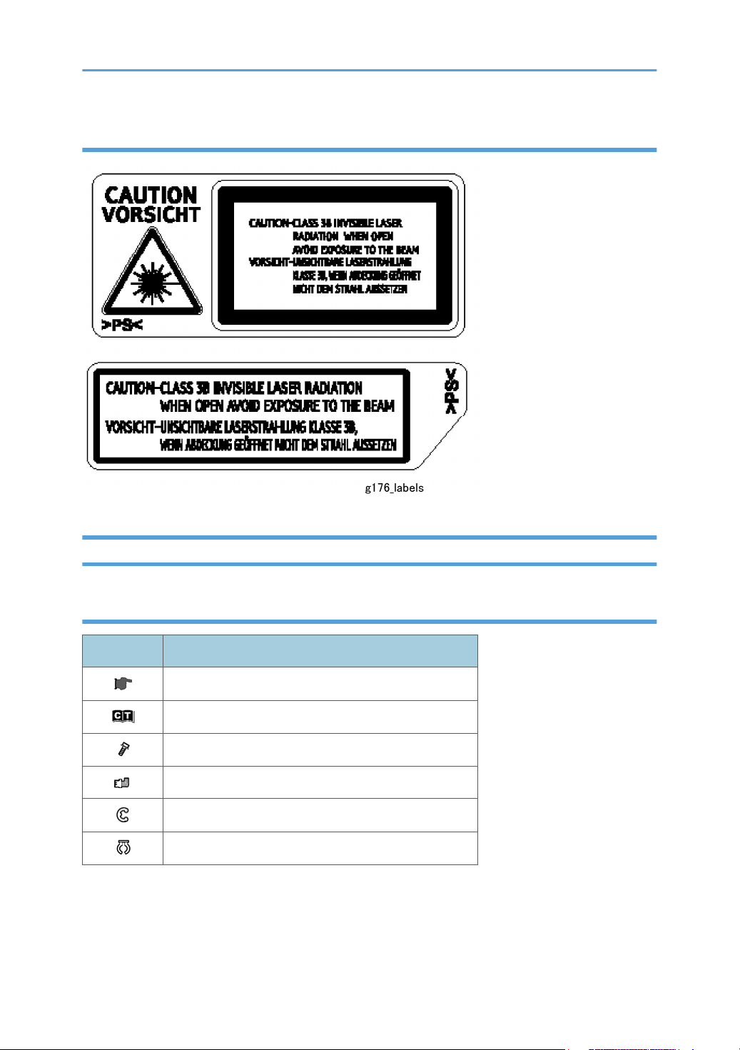
Caution Labels
Conventions
Conventions
Symbol What it means
Refer to section number
See Core Tech Manual for details
Screw
Connector
E-ring
C-ring
The following notations are used in text to describe the direction of paper feed: lengthwise and
sideways. The annotations “SEF” and “LEF” denote “Short Edge Feed” and “Long Edge Feed”. (The
arrows indicate the direction of paper feed.)
3

4

TABLE OF CONTENTS
Safety, Conventions............................................................................................................................................1
Safety...............................................................................................................................................................1
Conventions....................................................................................................................................................3
1. Product Information
Specifications....................................................................................................................................................11
Machine Configuration....................................................................................................................................12
System Components....................................................................................................................................12
Overview..........................................................................................................................................................15
Mechanical Component Layout ................................................................................................................15
Drive Layout..................................................................................................................................................16
Paper Path ...................................................................................................................................................17
2. Installation
Machine Installation ........................................................................................................................................19
Installation Requirements.................................................................................................................................20
Environment..................................................................................................................................................20
Machine Level..............................................................................................................................................20
Minimum Operational Space Requirements.............................................................................................21
Power Supply...............................................................................................................................................21
Controller Options............................................................................................................................................23
Overview......................................................................................................................................................23
Installing the SD Memory Card Options....................................................................................................24
SD Card Application Move........................................................................................................................26
IEEE 802.11 a/g (Wireless LAN)..............................................................................................................28
IEEE 1284 Interface Board.........................................................................................................................31
Gigabit Ethernet...........................................................................................................................................33
Memory Unit Type G 256MB / I 512MB (Only for M020)..................................................................35
Hard Disk Drive Type 2670 (Only for M020).........................................................................................37
Check All Connections................................................................................................................................40
IC Card Reader (External options) Attaching Location............................................................................40
Paper Feed Unit TK1120 (M386)..................................................................................................................41
Accessory Check..........................................................................................................................................41
Installation Procedure..................................................................................................................................41
When stacking four optional paper feed units..........................................................................................43
5

Paper Feed Unit TK1130 (M389)..................................................................................................................46
Accessory Check..........................................................................................................................................46
Installation Procedure
When stacking four optional paper feed units..........................................................................................48
..................................................................................................................................46
3. Preventive Maintenance
Maintenance Tables........................................................................................................................................51
User Maintenance.......................................................................................................................................51
Service Maintenance...................................................................................................................................51
PM Parts Settings
Before Removing the Old PM Parts............................................................................................................52
After Installing the New PM parts...............................................................................................................52
Operation Check.........................................................................................................................................52
..............................................................................................................................................52
4. Replacement and Adjustment
General Precautions........................................................................................................................................53
Precautions on Disassembly .......................................................................................................................53
Releasing Plastic Latches.............................................................................................................................54
After servicing the machine.........................................................................................................................54
Covers...............................................................................................................................................................56
Right Cover...................................................................................................................................................56
Left Cover......................................................................................................................................................57
Upper Cover
Front Cover...................................................................................................................................................59
Rear Cover...................................................................................................................................................61
Operation Panel...........................................................................................................................................62
Laser Unit..........................................................................................................................................................64
Caution Decal Locations.............................................................................................................................64
Laser Unit......................................................................................................................................................64
Polygon Mirror Motor ................................................................................................................................66
Laser Synchronization Detector..................................................................................................................67
Transfer Roller...................................................................................................................................................69
Fusing................................................................................................................................................................70
Fusing Unit....................................................................................................................................................70
Hot Roller and Pressure Roller Sections.....................................................................................................70
6
................................................................................................................................................58

Fusing Lamp..................................................................................................................................................71
Hot Roller......................................................................................................................................................72
Fusing Thermistor..........................................................................................................................................73
Thermostats
Pressure Roller..............................................................................................................................................74
Fusing Cleaning Roller.................................................................................................................................75
Paper Feed........................................................................................................................................................77
Paper Feed Roller........................................................................................................................................77
Friction Pad...................................................................................................................................................77
Paper End Sensor.........................................................................................................................................79
Remaining Paper Sensors 1 and 2.............................................................................................................81
Registration Sensor......................................................................................................................................83
By-pass Tray.....................................................................................................................................................85
By-pass Tray unit..........................................................................................................................................85
By-pass Feed Roller.....................................................................................................................................85
By-pass Friction Pad....................................................................................................................................87
By-pass Paper Sensor..................................................................................................................................88
Duplex...............................................................................................................................................................89
Duplex Unit...................................................................................................................................................89
Duplex Entrance Sensor..............................................................................................................................89
...................................................................................................................................................74
Duplex Relay Sensor...................................................................................................................................90
Paper Exit..........................................................................................................................................................93
Paper Overflow Sensor...............................................................................................................................93
Paper Exit Sensor.........................................................................................................................................93
Electrical Components.....................................................................................................................................96
Controller Board..........................................................................................................................................96
Controller Box..............................................................................................................................................97
PSU and PSU cover.....................................................................................................................................98
Engine Board.............................................................................................................................................100
Engine Board Bracket...............................................................................................................................102
Engine Board with Bracket.......................................................................................................................103
RFID (Radio Frequency ID).......................................................................................................................105
HVPS (High Voltage Power Supply)........................................................................................................105
7

Operation Panel unit.................................................................................................................................105
NVRAM and EEPROM.............................................................................................................................109
Switches..........................................................................................................................................................112
Tray Set Switch and Paper Size detection Sensor Board......................................................................112
Rear-left Interlock switch...........................................................................................................................112
Rear-right Interlock Switch........................................................................................................................113
Front Interlock Switch................................................................................................................................114
Clutches..........................................................................................................................................................115
Overview....................................................................................................................................................115
Registration Clutch
Relay Clutch...............................................................................................................................................116
By-pass Feed Clutch..................................................................................................................................116
Paper Feed Clutch.....................................................................................................................................117
Fans.................................................................................................................................................................118
Overview....................................................................................................................................................118
AIO Fan......................................................................................................................................................118
Exhaust Fan................................................................................................................................................119
PSU Fan......................................................................................................................................................119
Transfer Thermistor....................................................................................................................................120
Other Electrical Components........................................................................................................................121
HDD (option for M020)...........................................................................................................................121
DIMM (option for M020)........................................................................................................................121
Duplex Junction Solenoid.........................................................................................................................122
Toner End Sensor......................................................................................................................................123
Drive Section..................................................................................................................................................125
Overview....................................................................................................................................................125
.....................................................................................................................................115
Main Motor Gear Assy.............................................................................................................................125
Main Motor................................................................................................................................................126
Paper Exit Motor........................................................................................................................................128
Duplex motor.............................................................................................................................................129
5. System Maintenance Reference
Printer Service Mode.....................................................................................................................................131
SP1-XXX (Service Mode)..........................................................................................................................131
8

Engine Service Mode....................................................................................................................................138
Engine Mode Table...................................................................................................................................138
Firmware Update
Type of Firmware.......................................................................................................................................228
Precautions.................................................................................................................................................228
Machine Firmware Update......................................................................................................................229
NVRAM Data Upload/Download..............................................................................................................231
Uploading NVRAM Data.........................................................................................................................231
Downloading NVRAM Data....................................................................................................................232
SD Card Application Move..........................................................................................................................234
Overview....................................................................................................................................................234
Move Exec.................................................................................................................................................234
Undo Exec..................................................................................................................................................235
Menu Mode...................................................................................................................................................237
Controller Board DIP Switches.....................................................................................................................240
Card Save Function.......................................................................................................................................241
Overview....................................................................................................................................................241
Procedure...................................................................................................................................................241
...........................................................................................................................................228
6. Troubleshooting
Service Call Conditions.................................................................................................................................245
Summary....................................................................................................................................................245
SC Code Descriptions...............................................................................................................................246
Error Messages..............................................................................................................................................270
Common error messages..........................................................................................................................270
Jam Detection.................................................................................................................................................275
Paper Jam Display.....................................................................................................................................275
Paper Jam Sensors....................................................................................................................................275
Jam Codes and Display Codes................................................................................................................276
Initial Jam Relations...................................................................................................................................278
General Troubleshooting..............................................................................................................................279
Image Adjustment......................................................................................................................................279
Skew Adjustment.......................................................................................................................................279
Streaks in the Sub Scan Direction............................................................................................................280
9

7. Energy Saving
Energy Save...................................................................................................................................................281
Energy Saver Modes................................................................................................................................281
Energy Save Effectiveness........................................................................................................................282
Paper Save.....................................................................................................................................................284
Effectiveness of Duplex/Combine Function............................................................................................284
INDEX...........................................................................................................................................................287
10

1. Product Information
1
Specifications
See Appendices:
• Appendices: Basic Specifications
• Appendices: Controller Specifications
11
1. Product Information
1
Machine Configuration
System Components
12
Main
Item Machine code Remarks
45 ppm (A4 - SEF)
Mainframe (45 / 47 ppm) M020
47 ppm (LT - SEF)
50 ppm (A4 - SEF)
Mainframe (50 / 52 ppm) M021
52 ppm (LT - SEF)
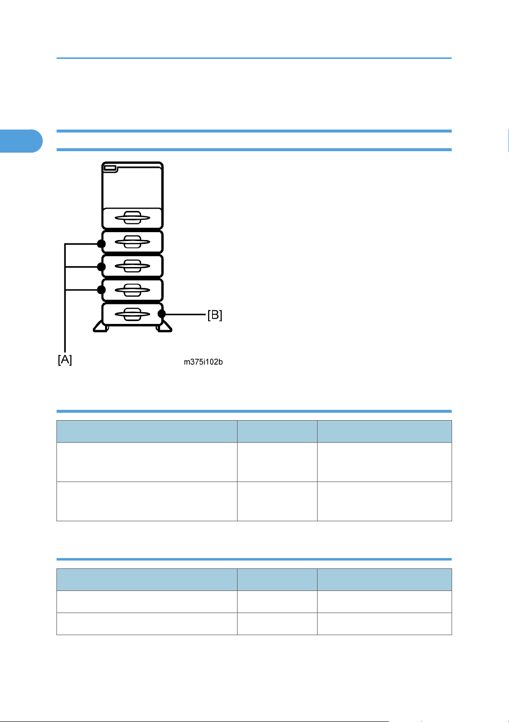
Options
Item Machine code Remarks
Paper Feed Unit TK1120 [A] M386 Without casters
Paper Feed Unit TK1130 [B] M389 With casters
Machine Configuration
1
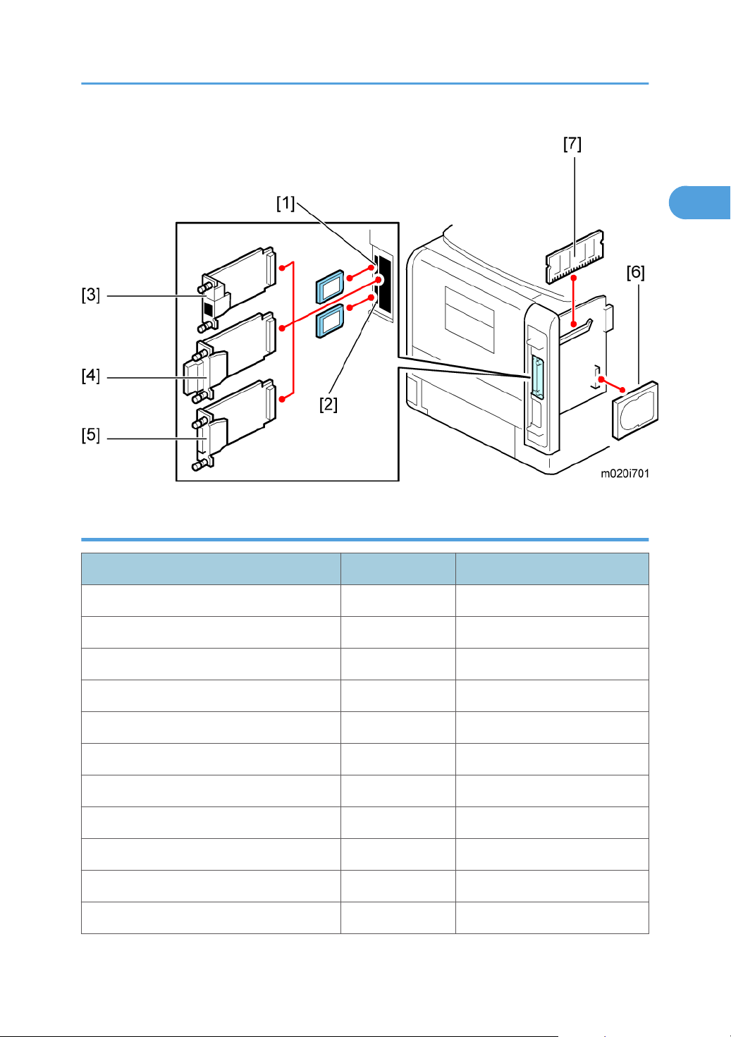
Internal options
Item Machine code Remarks
Memory Unit Type G 256 MB [7] D362 Optional for M020
Memory Unit Type I 512 MB [7] D435 Optional for M020
Hard Disk Drive Type 4310 [6] M394 Optional for M020
IEEE 1284 Interface Board Type A [5] B679
IEEE 802.11a/g interface Unit Type L [4] M344 For NA
IEEE 802.11a/g Interface Unit Type M [4] M344 For EU
Gigabit Ethernet Board Type A [3] G874
Gigabit Ethernet Board Type C [3] M397 For NA
SD Card for Netware Printing Type E [1] M388-03
IPDS Unit Type 5200 [1] M388-04 For NA
IPDS Unit Type 5200 [1] M388-05 For EU
13

1. Product Information
1
Item Machine code Remarks
SD Card for Fonts Type C [1] M352 For EU
14
Overview
1
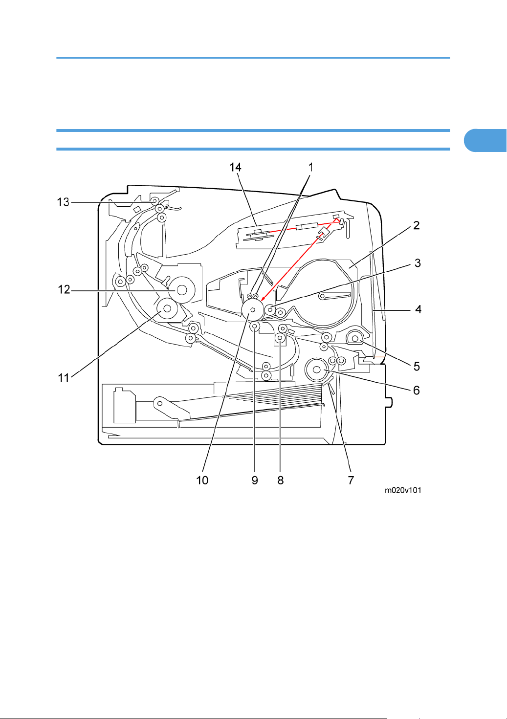
Mechanical Component Layout
Overview
1. Charge roller
Cartridge (AIO-type)
2.
3.
Development roller
4. By-pass feed tray
5. By-pass feed roller
6. Paper feed roller
7. Friction pad
8. Registration roller
9. Transfer roller
10. Drum
11. Pressure roller
12. Hot roller
13. Paper exit roller
14. Laser unit
15
1. Product Information
1
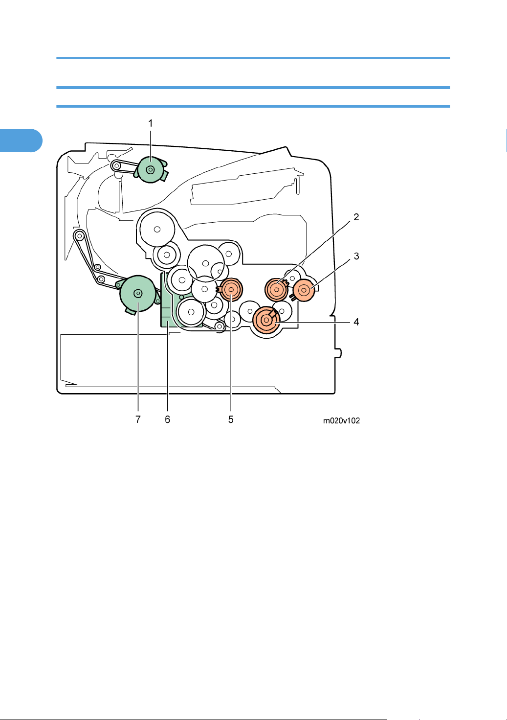
Drive Layout
16
1. Paper exit motor
2. Relay clutch
By-pass feed clutch
3.
4. Paper feed clutch
5. Registration clutch
6. Main motor
7. Duplex motor
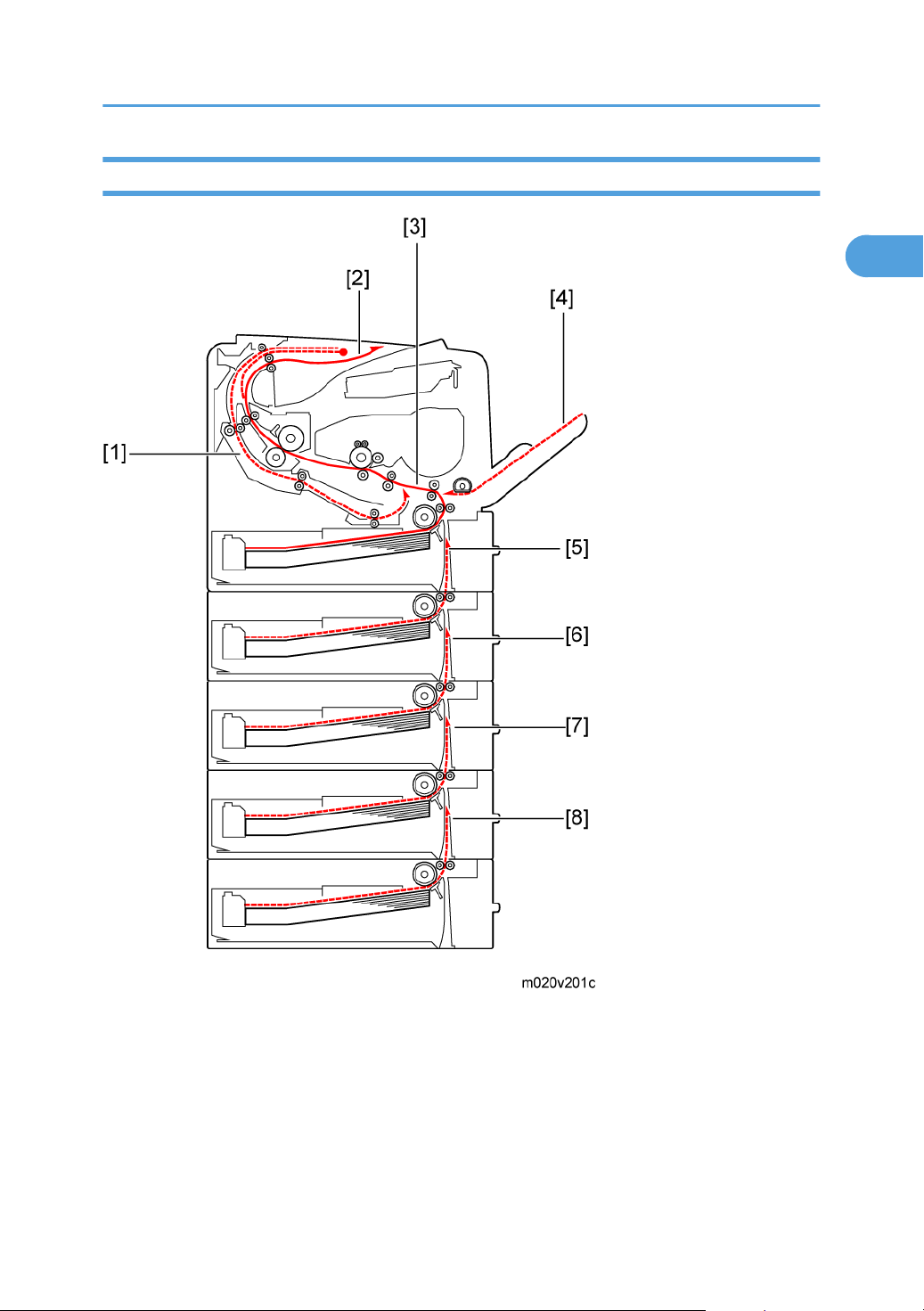
Paper Path
1
Overview
1. Paper feed through duplex unit
2. Paper exit to the paper stack
Paper feed from tray 1
3.
4. Paper feed from by-pass tray
5. Paper feed from optional PFU (tray 2)
6. Paper feed from optional PFU (tray 3)
17

1. Product Information
1
7. Paper feed from optional PFU (tray 4)
8. Paper feed from optional PFU (tray 5)
18

2. Installation
2
Machine Installation
Refer to the following sections for installation details for all models.
Category Item Machine code References
Main unit -
Paper Feed Unit TK1120 M386 p.41
Paper Feed Unit TK1130 M389 p.46
Memory Unit Type G 256 MB D362
Memory Unit Type I 512 MB D435
Hard Disk Drive Type 4310 M394
IEEE 802.11a/g interface Unit
Type L (NA) *1
Options
IEEE 802.11a/g interface Unit
Type M (EU) *1
IEEE 1284 Interface Board Type A B679
Gigabit Ethernet Board Type A *1 G874
Gigabit Ethernet Board Type C *1 M397
M020/
M021
M344
M344
Quick Installation Guide
p.23, p.24
IPDS Unit Type 5200 D571
SD Card for Netware Printing Type
E
Drivers - Software Guide, Section 1
*1: These units cannot be installed at the same time.
M388-03 Software Guide, Section 6
19
2. Installation
2
Installation Requirements
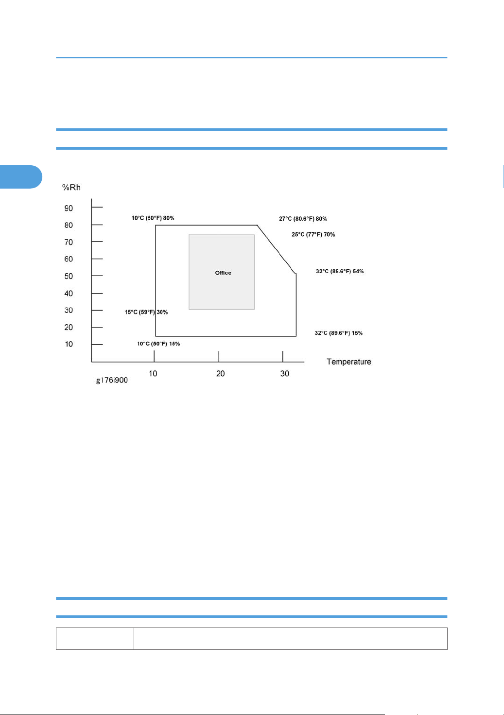
Environment
–Temperature and Humidity Chart–
• Temperature Range: 10°C to 32°C (50°F to 89.6°F)
• Humidity Range: 15% to 80% RH
•
• Ventilation: Room air should turn over at least 3 times/hr/person
• Ambient Dust: Less than 0.1 mg/m
• Do not install the machine where it will be exposed to direct sunlight or to direct airflow (from a fan,
• Do not install the machine where it will be exposed to corrosive gas.
• Install the machine at a location lower than 2,000 m (6,560 ft.) above sea level.
• Place the machine on a firm and level base.
• Do not install the machine where it may be subjected to strong vibration.
Machine Level
Front to back: Within 5 mm (0.2") of level
20
Ambient Illumination: Less than 1,500 lux (Do not expose to direct sunlight.)
3
air conditioner, air cleaner, etc.).
Right to left: Within 5 mm (0.2") of level
2
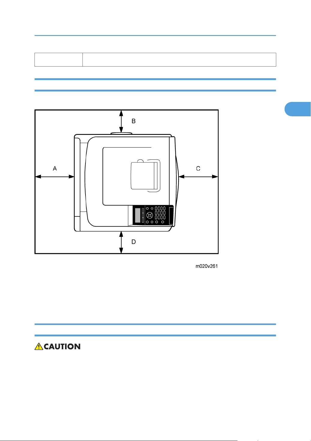
Minimum Operational Space Requirements
Place the machine near the power source, providing clearance as shown.
Installation Requirements
A: Rear – 200 mm (7.9")
B: Right – 100 mm (4.0")
C: Front – 350 mm (13.8")
D: Left – 100 mm (4.0")
Power Supply
• Make sure that the wall outlet is near the machine and easily accessible. After completing
installation, make sure the plug fits firmly into the outlet.
• Avoid multiple connections to the same power outlet.
Be sure to ground the machine.
•
Input voltage:
21

2. Installation
2
North America: 120 – 127 V, 60 Hz, 12 A
Europe/Asia: 220 – 240 V, 50/60 Hz, 8 A
Image quality guaranteed at rated voltage ± 10%.
Operation guaranteed at rated voltage ± 15%.
22
Controller Options
2
Controller Options
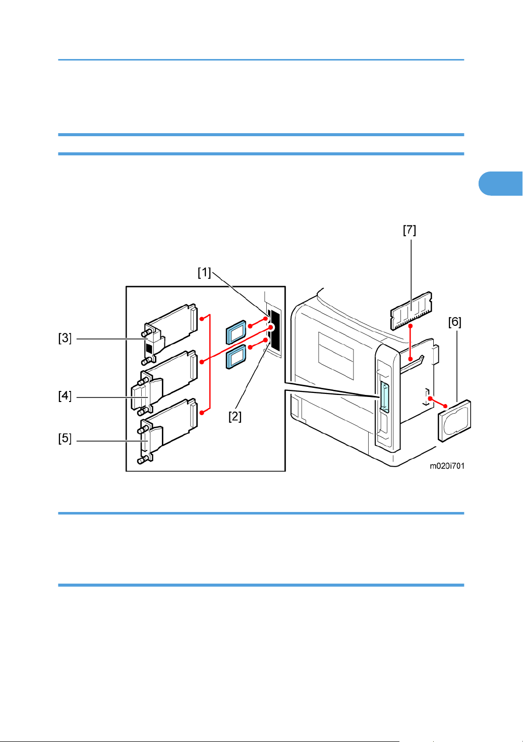
Overview
This machine has an I/F card slot for optional I/F connections and SD card slots.
After you install an option, check that the machine can recognize it (see "Check All Connections" at the
end of this section).
I/F Card Slots
• The I/F slot is used for one of the optional I/F connections (only one can be installed): Gigabit
Ethernet [3], IEEE802.11a/g (Wireless LAN) [4] or IEEE 1284 interface board [5].
SD Card Slots
• Slot 1 [1] (Upper) is used for the Security Card (standard) and IPDS Unit.
If IPDS Unit is to be installed, first merge IPDS application into the Security Card with SP mode
• Slot 2 [2] (Lower) is used for the VM card and service (for example, updating the firmware).
23
2. Installation
2
SDRAM slot
• The SDRAM slot is used for the SDRAM memory [7] (Standard for type M021, optional for type
M020).
Hard disk connector
• Hard disk connector is used for the hard disk [6] (Standard for type M021, optional for type
M020) installation.
Installing the SD Memory Card Options
Installation
• Keep SD memory cards out of reach of children. If a child swallows an SD memory card, consult a
doctor immediately.
• Do not subject the card to physical shocks.
• The VM card is optional for M020 models only. To use it, the optional 512 MB SDRAM module
must be installed.
Check the contents of the package.
1.
2. Turn off the power, and then unplug the power cord.
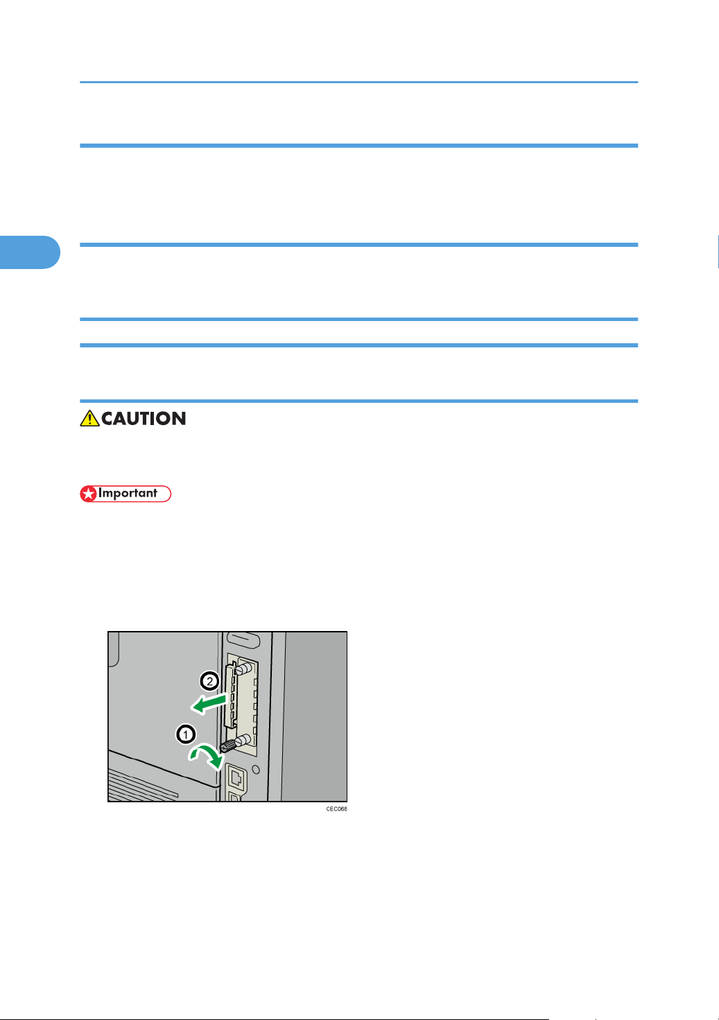
3. Remove the screw, and then carefully remove the cover of the SD card slot.
24

Controller Options
2
4. Carefully push in the SD card (notched corner downward and leading), until it clicks into place.
Insert the SD card in the appropriate slot as follows:
• Upper slot: SD font card, NetWare card, Security SD card (Standard for M020), IPDS card.
Lower slot: For service only (Firmware update, application move, etc.)
•
The SD card supplied with the optional hard disk (M020 model only) can be used in either of the
two slots.
5. Reattach the cover over the SD card. Fasten the screw to secure the cover.
• Do not touch the card while the printer is in use. It may come loose, even if pushed only slightly. The
slot cover must be reattached.
• You can confirm that the SD card was installed correctly by checking the control panel menu.
Depending on the SD card, certain menu items appear on the display.
SD card supplied with the optional hard disk (M020 model only): Make sure [Machine Data
•
Encryption] appears in [Security Options]. Depending on settings, [Machine Data Encryption]
might not appear. For details about how to confirm this setting, consult your administrator.
• NetWare card: Make sure [NetWare] appears in [Effective Protocol] under [Network].
25

2. Installation
2
SD Card Application Move
• The PostScript3 application and fonts cannot be moved to another SD card. However, other
applications can be moved onto the PostScript3 SD card.
Overview
The service program "SD Card Appli Move" (SP5-873) lets you copy application programs from one
SD card to another SD card.
Slot 1 (Upper) is used to store application programs. But there are 3 possible applications (PostScript 3,
DOS (DataOverwriteSecurity) unit, PictBridge). You cannot run application programs from Slot 2
(Lower). However you can move application programs from Slot 2 (Lower) to Slot 1 (Upper) with the
following procedure.
Make sure that the target SD card has enough space.
1. Enter SP5873 "SD Card Appli Move".
Then move the application from the SD Card in Slot 2 (Lower) to the SD Card in Slot 1 (Upper).
2.
• Do steps 1 - 2 again if you want to move another application program.
3. Exit the SP mode.
Be very careful when you do the SD Card Appli Move procedure:
The data necessary for authentication is transferred with the application program from an SD card
•
to another SD card. Authentication fails if you try to use the SD card after you copy the application
program from one card to another card.
• Do not use the SD card if it has been used before for other purposes. Normal operation is not
guaranteed when such an SD card is used.
• Keep the SD card in a safe place after you copy the application program from one card to another
card. This is done for the following reasons:
1) The SD card can be the only proof that the user is licensed to use the application program.
2) You may need to check the SD card and its data to solve a problem in the future.
Move Exec
The menu "Move Exec" (SP5873-001) lets you copy application programs from the original SD card to
another SD card.
26

Controller Options
2
• Do not set ON (Lock) the write-protect switch of the system SD card or application SD card on the
machine. If the write-protect switch is ON, a download error (e.g. Error Code 44) occurs during a
firmware upgrade or application merge.
1. Turn the main switch off.
Make sure that an SD card is in SD Card Slot 1 (Upper). The application program is copied to this
2.
SD card.
3. Insert the SD card with the application program in SD Card Slot 2 (Lower).The application
program is copied from this SD card.
4. Turn the main switch on.
5. Start the SP mode.
6. Select SP5873-001 "Move Exec."
7. Follow the messages shown on the operation panel.
8. Turn the main switch off.
9. Remove the SD card from SD Card Slot 2 (Lower).
10. Turn the main switch on.
11. Check that the application programs run normally.
Undo Exec
"Undo Exec" (SP5873-002) lets you copy back application programs from an SD card to the original
SD card. You can use this program when, for example, you have mistakenly copied some programs by
using Move Exec (SP5873-001).
• Do not set ON (Lock) the write protect switch of the system SD card or application SD card on the
machine. If the write protect switch is ON, a download error (e.g. Error Code 44) occurs during a
firmware upgrade or application merge.
1. Turn the main switch off.
Insert the original SD card in SD Card Slot 2 (Lower). The application program is copied back into
2.
this card.
3. Insert the SD card with the application program in SD Card Slot 1 (Upper).The application
program is copied back from this SD card.
4. Turn the main switch on.
5. Start the SP mode.
6. Select SP5873-002 "Undo Exec."
7. Follow the messages shown on the operation panel.
27

2. Installation
2
8. Turn the main switch off.
9. Remove the SD card from SD Card Slot 2 (Lower).
• This step assumes that the application programs in the SD card are used by the machine.
10. Turn the main switch on.
Check that the application programs run normally.
11.
12. Make sure that the machine can recognize the option (see "p.40" at the end of this section).
IEEE 802.11 a/g (Wireless LAN)
Installation Procedure
• Unplug the main machine power cord before you do the following procedure.
You can only install one of the network interfaces or printer enhanced option at one time: IEEE 802.11
a/g (Wireless LAN), Gigabit Ethernet, or File Format Converter.
1. Remove the two screws and remove the cover of the slot in which the Wireless LAN interface board
is to be installed.
28
 Loading...