

Page 1

Vacuum Feed LCIT RT5100
Machine Code: D777-17
Field Service Manual
V1.1
March 2015
Page 2

Page 3

Revision History
This is the Revision History for the Vacuum Feed LCIT RT5100 service manual.
Version Date Changes
Text, Illustrations. In procedures the order of the text and
illustrations has been reversed. For each step, the text description
Ver. 1.1 31 Mar 2015
(action) is followed by the relevant illustration. The callouts [A], [B],
[C] in text refer to the illustration below, not above.
PSU cooling fans. The naming of PSU cooling fan 1, and PSU
cooling fan 2 has been corrected.
1
Page 4
Safety, Conventions, Trademarks
Conventions
Common Terms
This is a list of symbols and abbreviations used in this manual.
Symbol What it means
Screw
Connector
E-ring
Clip ring
Harness clamp
FFC Flexible Film Cable
JG Junction Gate
LE Leading Edge of paper
LEF Long Edge Feed
SEF Short Edge Feed
TE Trailing Edge of paper
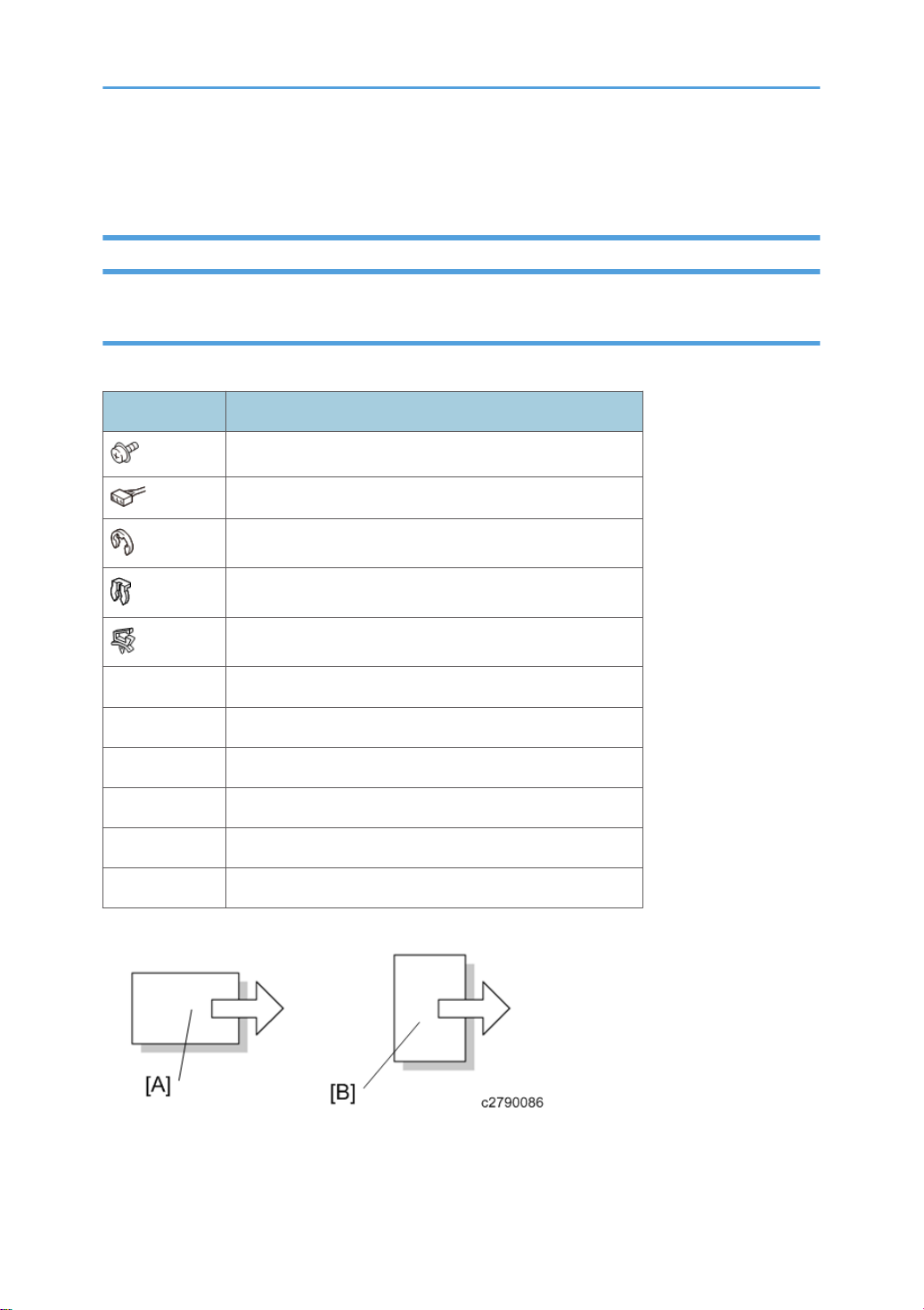
[A] Short Edge Feed (SEF)
[B] Long Edge Feed (LEF)
2
Page 5

Warnings, Cautions, Notes
In this manual, the following important symbols and notations are used.
• A Warning indicates a potentially hazardous situation. Failure to obey a Warning could result in
death or serious injury.
• A Caution indicates a potentially hazardous situation. Failure to obey a Caution could result in
minor or moderate injury or damage to the machine or other property.
• Obey these guidelines to avoid problems such as misfeeds, damage to originals, loss of valuable
data and to prevent damage to the machine.
• This information provides tips and advice about how to best service the machine.
Responsibilities of the Customer Engineer
Reference Material for Maintenance
• Maintenance shall be done using the special tools and procedures prescribed for maintenance of
the machine described in the reference materials (service manuals, technical bulletins, operating
instructions, and safety guidelines for customer engineers).
• Use only consumable supplies and replacement parts designed for use of the machine.
The Aim of Anti-tip Components and Precautions
The anti-tip components are necessary for meeting the requirements of IEC60950-1, the international
standard for safety.
The aim of these components is to prevent heavy products as a result of people running into or leaning
onto the products. This can lead to serious accidents such as persons becoming trapped under the
product. (U.S.: UL60950-1, Europe: EN60950-1)
Therefore, removal of such components must always be with the consent of the customer. Never remove
them without the customer's consent.
3
Page 6

TABLE OF CONTENTS
Revision History...................................................................................................................................................1
Safety, Conventions, Trademarks......................................................................................................................2
Conventions.................................................................................................................................................... 2
Common Terms...................................................................................................................................... 2
Warnings, Cautions, Notes...........................................................................................................................3
Responsibilities of the Customer Engineer.................................................................................................... 3
Reference Material for Maintenance...................................................................................................3
The Aim of Anti-tip Components and Precautions....................................................................................... 3
1. Replacement and Adjustment
Exterior Covers....................................................................................................................................................7
Right Upper Cover......................................................................................................................................... 7
Right Lower Cover.......................................................................................................................................... 7
Rear Right Cover............................................................................................................................................ 8
Rear Left Cover............................................................................................................................................... 8
Left Top Cover.................................................................................................................................................9
Center Top Cover........................................................................................................................................ 10
Right Top Cover........................................................................................................................................... 10
Front Corner Cover......................................................................................................................................11
Rear Corner Cover...................................................................................................................................... 12
Front Door.....................................................................................................................................................13
Upper Inner Cover.......................................................................................................................................13
Lower Inner Cover....................................................................................................................................... 15
Tray Front Cover (Tray 1, 2).......................................................................................................................15
Paper Feed Unit (Trays 1, 2)...........................................................................................................................16
Paper Tray.................................................................................................................................................... 16
Paper Feed Belt Unit.................................................................................................................................... 16
Paper Feed Belt............................................................................................................................................19
Paper End Sensor.........................................................................................................................................22
Paper Feed Sensor.......................................................................................................................................23
Transport Roller Unit.................................................................................................................................... 25
Float/Separation Fan Duct.........................................................................................................................26
Float Fan....................................................................................................................................................... 27
Re-installation...................................................................................................................................... 27
4
Page 7

Separation Fan.............................................................................................................................................27
Re-installation...................................................................................................................................... 28
Float Fan Shutter Solenoid.......................................................................................................................... 28
Paper Upper Limit Sensor 1, 2....................................................................................................................28
Main Paper Remaining Sensor................................................................................................................... 29
Sub Paper Remaining Sensor......................................................................................................................30
Paper Lower Limit Sensor............................................................................................................................ 31
LCIT Paper Length Sensor 1 and 2.............................................................................................................32
Tray Upper Limit Sensor.............................................................................................................................. 33
Side Fences (Front, Rear)............................................................................................................................ 35
Common Procedure for Removing the Side Fences (Front, Rear)...................................................35
Side Fence (Front)............................................................................................................................... 38
Side Fence (Rear)................................................................................................................................41
Paper Size Sensors...................................................................................................................................... 44
Side Fan........................................................................................................................................................45
Side Fan Shutter Solenoid...........................................................................................................................47
Rear Side...........................................................................................................................................................48
Main Board.................................................................................................................................................. 48
Tray 1 Pickup Belt Motor.............................................................................................................................48
Re-installation...................................................................................................................................... 49
Tray 1 Grip Motor....................................................................................................................................... 50
Re-installation...................................................................................................................................... 51
Tray 2 Pickup Belt Motor.............................................................................................................................51
Tray 2 Grip Motor....................................................................................................................................... 52
Suction Fan 1, 2 (Tray 1, 2)....................................................................................................................... 53
LCIT Lift Motor (Tray 1, 2)...........................................................................................................................54
Bypass Transport Motor 2...........................................................................................................................55
Re-installation...................................................................................................................................... 56
Transport Motor Cooling Fan..................................................................................................................... 57
Re-installation...................................................................................................................................... 58
Vertical Feed Unit.............................................................................................................................................59
Vertical Feed Unit.........................................................................................................................................59
Re-installation...................................................................................................................................... 62
5
Page 8

Tray 1 Vertical Transport Motor 1..............................................................................................................63
Tray 1 Vertical Transport Motor 2..............................................................................................................63
Tray 1 Transport Sensor.............................................................................................................................. 64
Tray 1 Vertical Transport Sensor................................................................................................................ 66
Tray 2 Vertical Transport Motor 1..............................................................................................................67
Tray 2 Vertical Transport Motor 2..............................................................................................................68
Re-installation...................................................................................................................................... 68
Tray 2 Vertical Transport Sensor................................................................................................................ 69
Tray 2 Transport Sensor.............................................................................................................................. 70
Vertical Transport Exit Motor...................................................................................................................... 72
Re-installation...................................................................................................................................... 73
Bypass Transport Sensor 2..........................................................................................................................74
LCIT Exit Motor.............................................................................................................................................74
LCIT Exit Roller Contact Motor....................................................................................................................75
Re-installation...................................................................................................................................... 76
LCIT Exit Sensor............................................................................................................................................76
LCIT Exit Roller Contact Sensor...................................................................................................................77
Vertical Transport Unit Cooling Fan........................................................................................................... 78
Vertical Transport Unit Cooling Fan Re-installation..........................................................................79
PSU Box............................................................................................................................................................ 81
PSU box........................................................................................................................................................81
PSU1, 2........................................................................................................................................................ 81
PSU Cooling Fan 1, 2................................................................................................................................. 83
Interlock Switch............................................................................................................................................ 84
AC Drive Board............................................................................................................................................85
Fuses on the PSU and AC drive board that can be replaced..........................................................86
6
Page 9
1. Replacement and Adjustment
Exterior Covers
Right Upper Cover
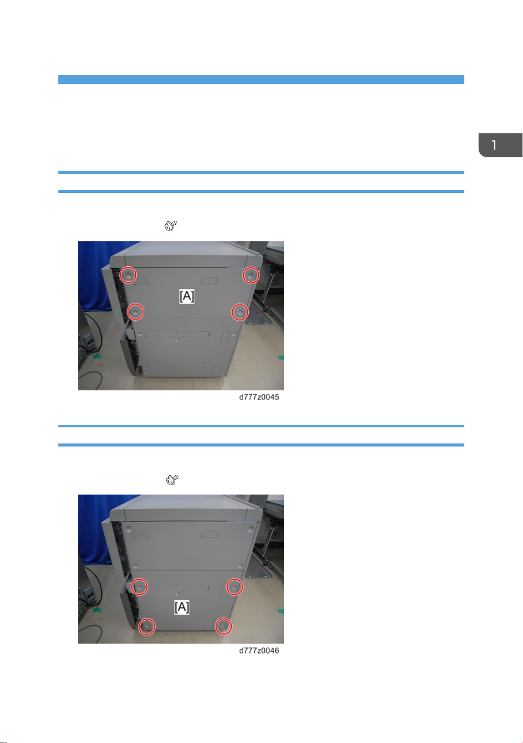
1. Open the paper tray 1 slightly.
2. Right upper cover [A]( x4)
Right Lower Cover
1. Open the paper trays 1 and 2 slightly.
2. Right lower cover [A] ( x5)
7
Page 10
1. Replacement and Adjustment
Rear Right Cover
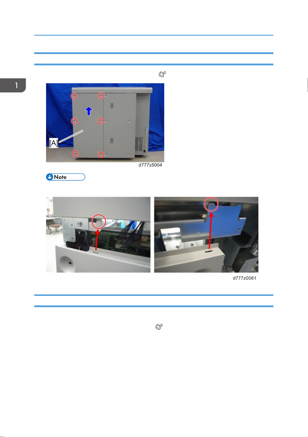
1. Lift the rear right cover [A] slightly and remove it ( x6).
• When attaching the rear right cover, hang it on the hook.
Rear Left Cover
1. Rear right cover (page 8 "Rear Right Cover")
2. Lift the rear left cover [A] slightly and remove it ( x10).
8
Page 11
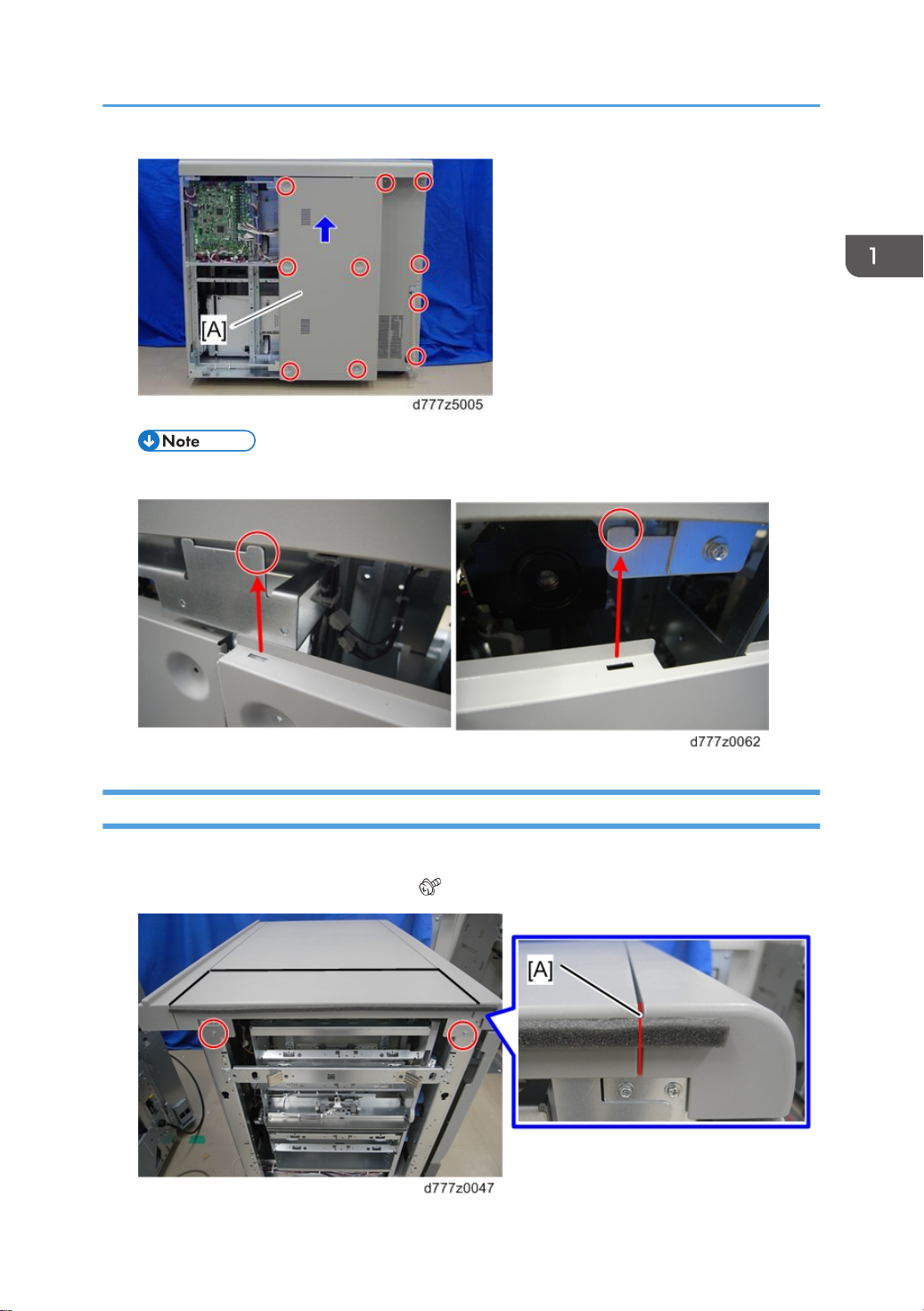
• When attaching the rear left cover, hang it on the hook.
Exterior Covers
Left Top Cover
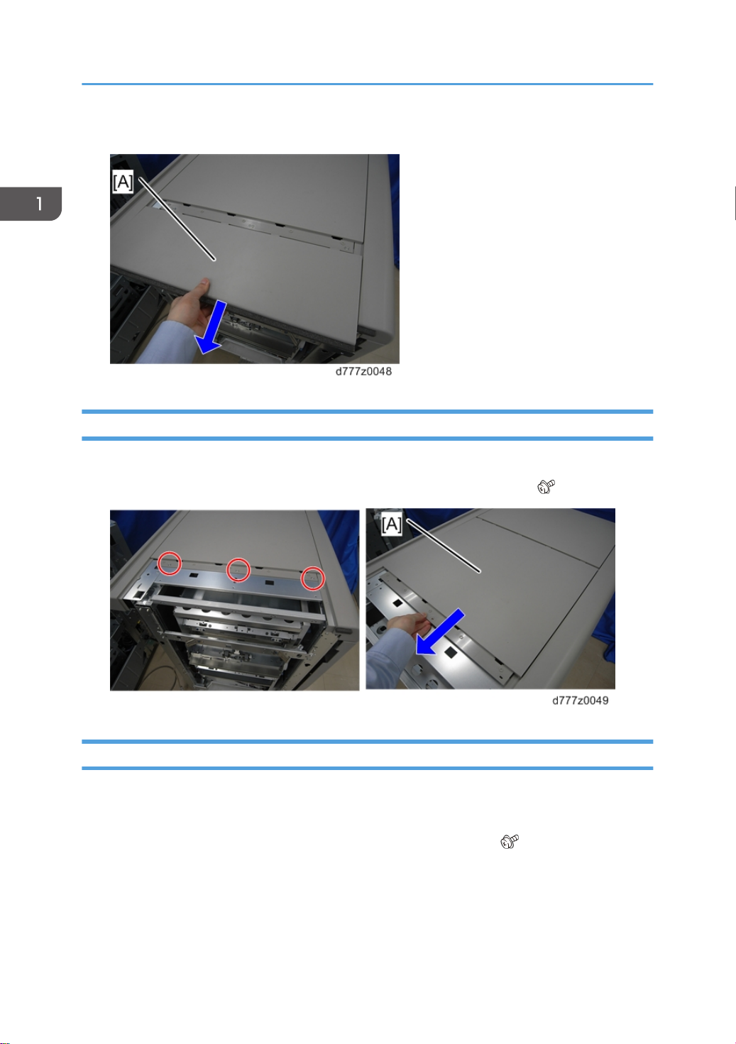
1. Cut the cushion at the position [A] along the groove.
2. Remove the screws on the left top cover ( x2).
9
Page 12
1. Replacement and Adjustment
3. Slide the left top cover [A] in the direction of the blue arrow and remove it.
Center Top Cover
1. Left top cover (page 9 "Left Top Cover")
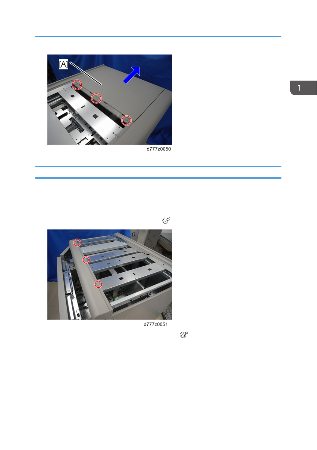
2. Slide the center top cover [A] in the direction of the blue arrow and remove it ( x3).
Right Top Cover
1. Left top cover (page 9 "Left Top Cover")
2. Center top cover (page 10 "Center Top Cover")
3. Slide the right top cover [A] in the direction of the arrow and remove it ( x3).
10
Page 13
Front Corner Cover
1. Left top cover (page 9 "Left Top Cover")
2. Center top cover (page 10 "Center Top Cover")
Exterior Covers
3. Right top cover (page 10 "Right Top Cover")
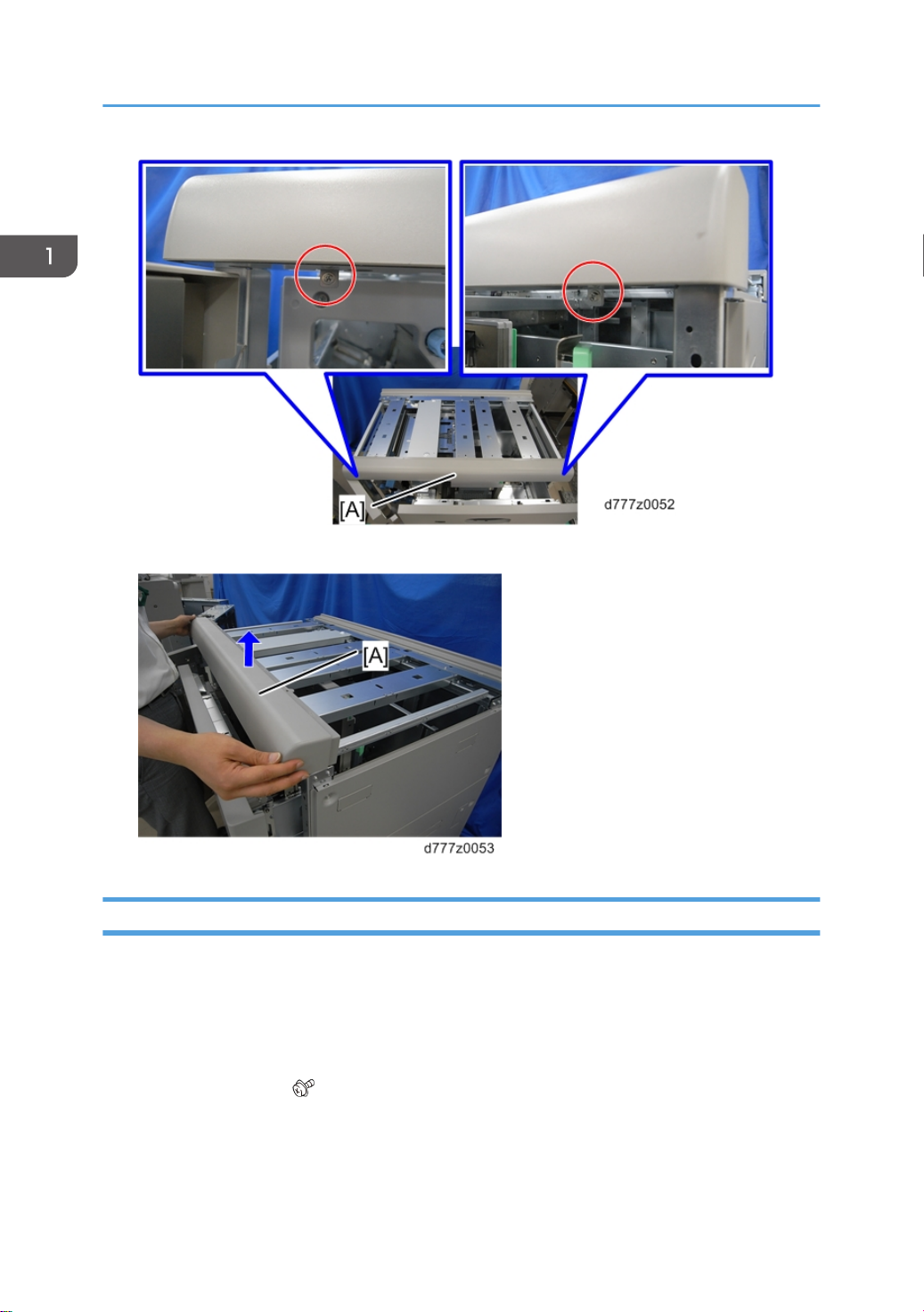
4. Remove the screws at the top of the front corner ( x3).
5. Remove the screws at the bottom of the front corner [A] ( x2).
11
Page 14
1. Replacement and Adjustment
6. Lift the front corner cover [A] and remove it.
Rear Corner Cover
1. Left top cover (page 9 "Left Top Cover")
2. Center top cover (page 10 "Center Top Cover")
3. Right top cover (page 10 "Right Top Cover")
4. Remove the rear right and rear left covers (page 8 "Rear Right Cover",page 8 "Rear Left Cover").
5. Rear corner cover [A]( x2)
12
Page 15
Front Door
1. Left top cover (page 9 "Left Top Cover")
2. Center top cover (page 10 "Center Top Cover")
Exterior Covers
3. Right top cover (page 10 "Right Top Cover")
4. Front corner cover (page 11 "Front Corner Cover")
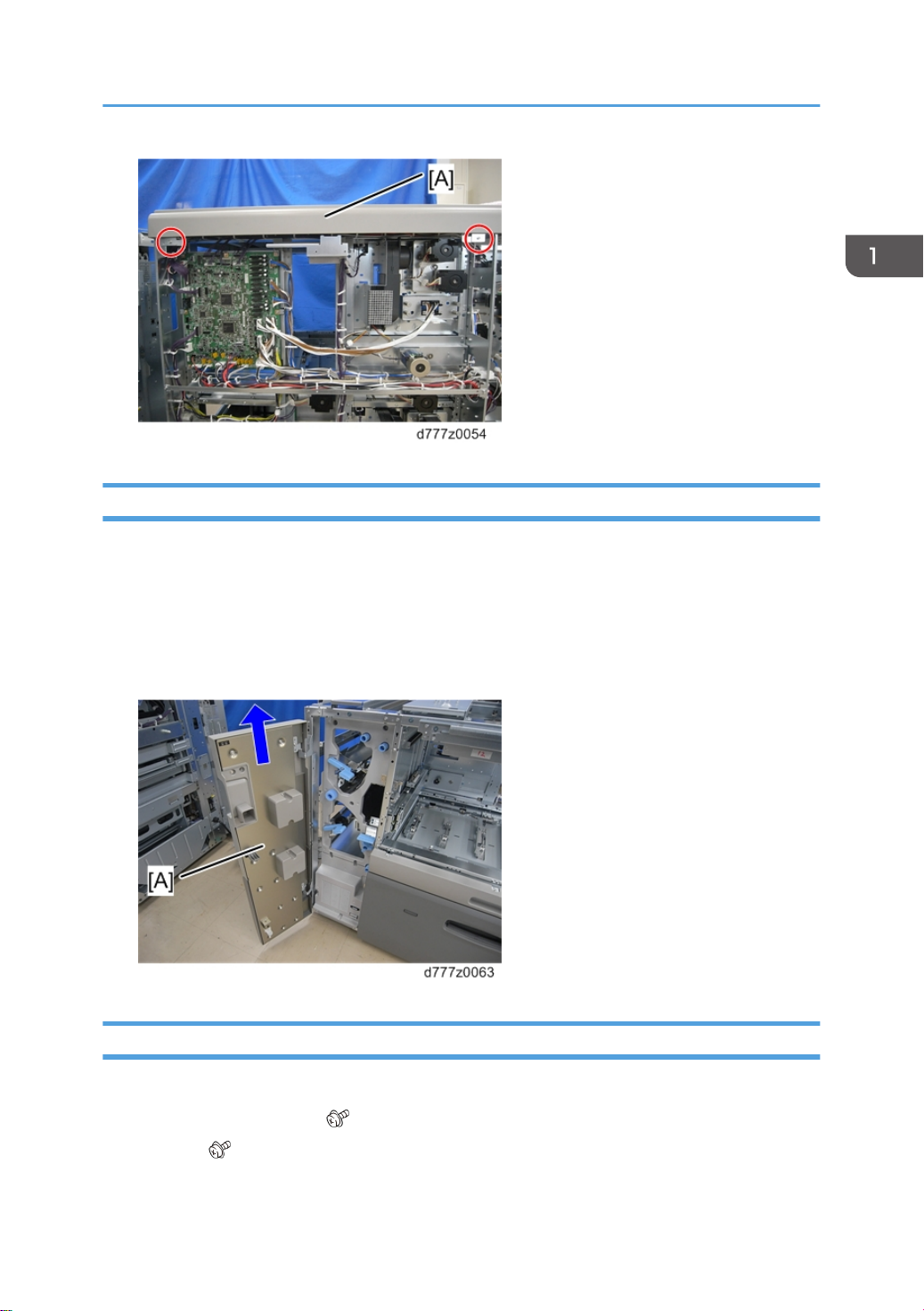
5. Lift the front door [A] and remove it.
Upper Inner Cover
1. Open the front door.
2. Remove the two levers [A] ( x1 each).
3. Knob [B] ( x1)
13
Page 16
1. Replacement and Adjustment
4. Raise the paper jam U9 clearing plate and remove the knob [A] ( x2).
14
5. Three knobs [A] ( x1 each)
6. Upper inner cover [B] ( x5)
Page 17
Lower Inner Cover
1. Open the front door.
2. Lower inner cover [A] ( x3)
Exterior Covers
Tray Front Cover (Tray 1, 2)
• The replacement procedure for tray front cover of tray 1 and 2 are the same. The following is the
procedure for replacing the tray front cover of tray 1.
1. Pull out the paper tray.
2. Lift the tray front cover [A] and remove it ( x4).
• The lower screw [B] is a shoulder screw.
15
Page 18
1. Replacement and Adjustment
Paper Feed Unit (Trays 1, 2)
• Do not pull out all trays in the vacuum feed LCIT RT5100 (when it is not linked to the main unit)
because it could fall over.
• Parts in paper trays 1 and 2 can be removed using the same procedure. The following are the
procedures for replacing the parts in tray 1.
Paper Tray
1. Tray front cover (page 15 "Tray Front Cover (Tray 1, 2)")
2. Paper tray ( x4)
• The tray weighs about 30 kg. It is heavy and requires careful handling by two persons.
Paper Feed Belt Unit
[A]: Tray 1 paper feed belt unit
[B]: Tray 2 paper feed belt unit
16
Page 19
1. Open the paper tray.
2. Remove the lock of the paper feed belt unit ( x2).
Paper Feed Unit (Trays 1, 2)
3. Hold the knob of the paper feed belt unit [A] and close the paper tray halfway.
4. Pull out the paper feed belt unit [A] and the paper tray together.
17
Page 20
1. Replacement and Adjustment
• The paper feed belt unit must be pulled out horizontally relative to the paper tray, to ensure that the
paper feed belt is not damaged by getting caught in the side fences or other parts.
• To prevent damaging the paper feed belt when you return the paper feed belt unit to its original
position, align the right and left guides [A] with the rail [B] on the paper tray side and raise them
slightly before replacing the unit.
18
Page 21
Paper Feed Unit (Trays 1, 2)
Paper Feed Belt
1. Paper feed belt unit (page 16 "Paper Feed Belt Unit")
2. Shaft [A]
3. Guide plate [A] ( x4)
19
Page 22
1. Replacement and Adjustment
4. Pull out the chamber [A] ( x2).
5. Bracket [A] ( x2)
20
Page 23
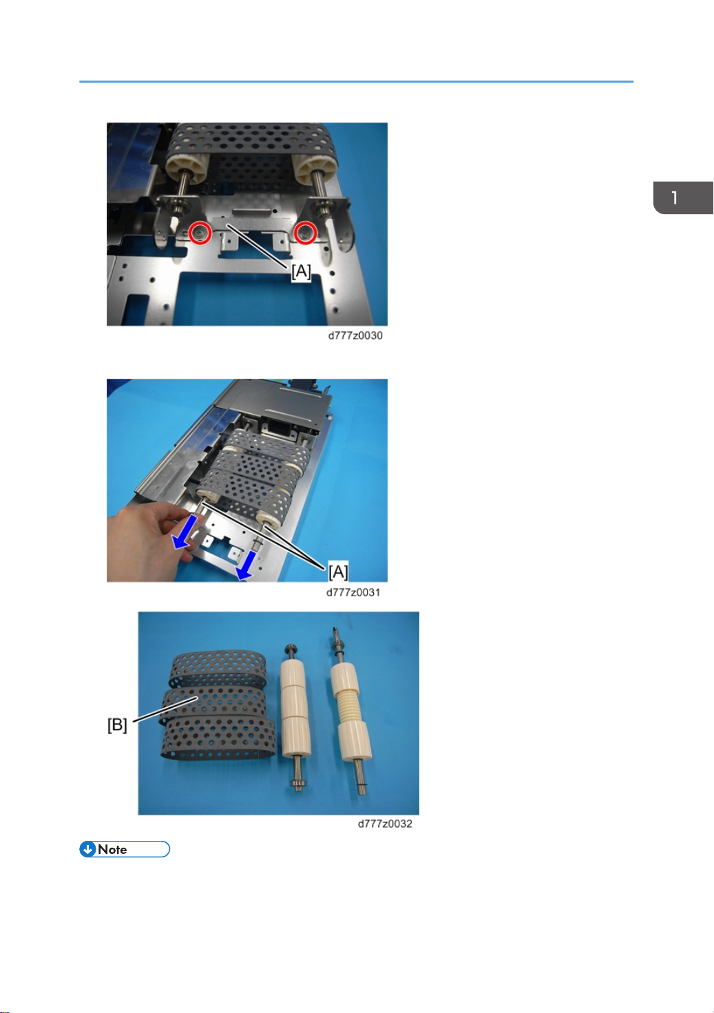
6. Remove the belt shaft [A] and the paper feed belt [B].
Paper Feed Unit (Trays 1, 2)
• During installation, turn the shaft to correct belt deflection before installing the chamber.
• When all parts have been assembled, turn the shaft once more to check for deflection, resistance
and other abnormalities before replacing the paper tray.
21
Page 24
1. Replacement and Adjustment
Paper End Sensor
1. Paper feed belt unit (page 16 "Paper Feed Belt Unit")
2. Rear harness ( x3, x1)
22
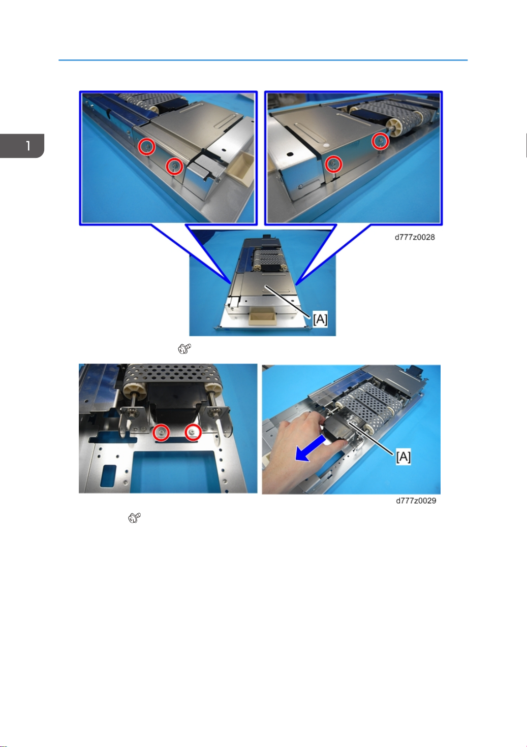
3. Center guide plate [A] ( x2)
Page 25
4. Paper end sensor [A] ( x2, x1, x1)
Paper Feed Unit (Trays 1, 2)
Paper Feed Sensor
• The replacement procedures for the paper feed sensor of the tray 1 and 2 are the same. The
following is the procedure for replacing the paper feed sensor of tray 1.
1. Pull out the paper tray.
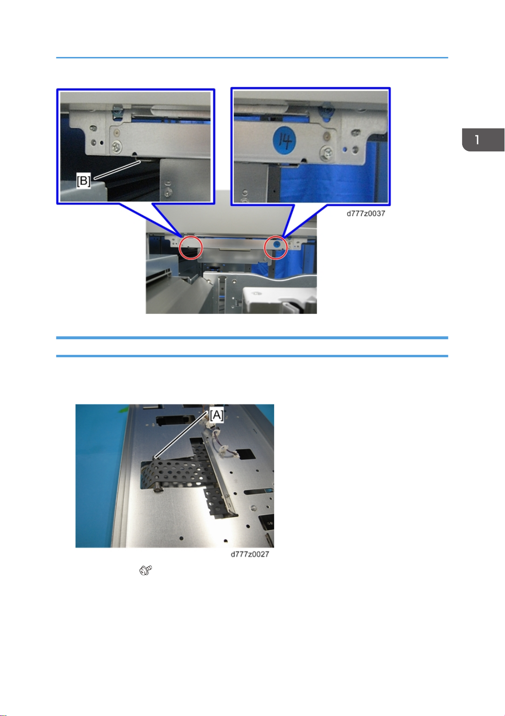
2. Remove the top cover [A] of the transport roller unit ( x2).
23
Page 26
1. Replacement and Adjustment
3. Paper feed sensor bracket [A] ( x2)
24
4. Paper feed sensor [A] ( x1, x1)
Page 27
Transport Roller Unit
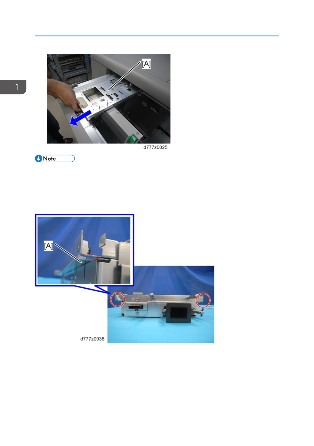
1. Open the front door [A] and pull out the paper tray [B].
2. Tray left top cover [A] ( x4)
Paper Feed Unit (Trays 1, 2)
3. Disconnect relay connector, and then remove transport roller unit [A] ( x1, x4)
25
Page 28

1. Replacement and Adjustment
Float/Separation Fan Duct
1. Transport roller unit (page 25 "Transport Roller Unit")
2. Remove the eight clamps and the three connectors.
3. Remove the float/separation fan duct [A] ( x6).
26
• When installing the float/separation fan duct, connect the connectors before installing the duct.
Installing the duct first will make it difficult to connect the connectors.
• Do not remove the bracket [A] that adjusts the position of the float/separation fan duct. This
bracket is factory installed and cannot be adjusted outside the factory.
Page 29

Float Fan
1. Float/separation fan duct (page 26 "Float/Separation Fan Duct")
2. Float fan [A] ( x2, x2)
Paper Feed Unit (Trays 1, 2)
Re-installation
Install the float fan so that its label faces to the right.
Separation Fan
1. Float/separation fan duct (page 26 "Float/Separation Fan Duct")
2. Separation fan [A] ( x2, x2)
27
Page 30

1. Replacement and Adjustment
Re-installation
Install the separation fan so that its label faces to the left.
Float Fan Shutter Solenoid
1. Paper tray (page 16 "Paper Tray")
2. Transport roller unit (page 25 "Transport Roller Unit")
3. Float/separation fan duct (page 26 "Float/Separation Fan Duct")
4. Float fan shutter solenoid [A] ( x2, x1)
Paper Upper Limit Sensor 1, 2
1. Transport roller unit (page 25 "Transport Roller Unit")
2. Float/separation fan duct (page 26 "Float/Separation Fan Duct")
3. Paper upper limit sensor 1 [A] ( x1, x1)
28
Page 31

4. Paper upper limit sensor 2 [A] ( x1, x1)
Paper Feed Unit (Trays 1, 2)
• The position of the paper upper limit sensor bracket [A] is adjusted at the factory. If it is removed,
make sure that it is reinstalled in the same position.
Main Paper Remaining Sensor
1. Transport roller unit (page 25 "Transport Roller Unit")
2. Float/separation fan duct (page 26 "Float/Separation Fan Duct")
3. Use your fingers to hold the pulley [A] in place while you remove it [A].
29
Page 32

1. Replacement and Adjustment
4. Main paper remaining sensor [A] ( x1)
Sub Paper Remaining Sensor
1. Open the front door [A] and pull out the paper tray [B].
2. Tray left top cover [A] ( x4)
30
Page 33

3. Sub paper remaining sensor bracket [A] ( x1, x1)
Paper Feed Unit (Trays 1, 2)
4. Sub paper remaining sensor [A] ( x1, x1)
Paper Lower Limit Sensor
1. Transport roller unit (page 25 "Transport Roller Unit")
2. Paper lower limit sensor bracket [A] ( x1)
31
Page 34

1. Replacement and Adjustment
3. Paper lower limit sensor [A] ( x1, x1)
LCIT Paper Length Sensor 1 and 2
1. Open the paper tray.
2. Hold the side fence lock to open the side fence [A].
3. Sensor cover [A] ( x2)
32
Page 35

4. Sensor bracket [A] ( x3, x1)
Paper Feed Unit (Trays 1, 2)
5. LCIT paper length sensor 1 [A] ( x1)
6. LCIT paper length sensor 2 [B] ( x1)
Tray Upper Limit Sensor
1. Paper tray (page 16 "Paper Tray")
33
Page 36

1. Replacement and Adjustment
2. Paper feed belt unit (page 16 "Paper Feed Belt Unit")
3. Tray upper limit sensor [A]
• The sensor pawl is on the rear of the frame. Access it from the rear of the main unit if it proves
difficult to remove it from the front.
4. Remove the rear right and left covers (page 8 "Rear Right Cover",page 8 "Rear Left Cover").
5. Bracket [A] ( x2, x4)
34
6. Remove the pawl of the tray upper limit sensor.
Page 37

Side Fences (Front, Rear)
Common Procedure for Removing the Side Fences (Front, Rear)
1. Tray front cover (page 15 "Tray Front Cover (Tray 1, 2)")
2. Paper tray (page 16 "Paper Tray")
3. Remove the plate [A] from the end fence side ( x4).
Paper Feed Unit (Trays 1, 2)
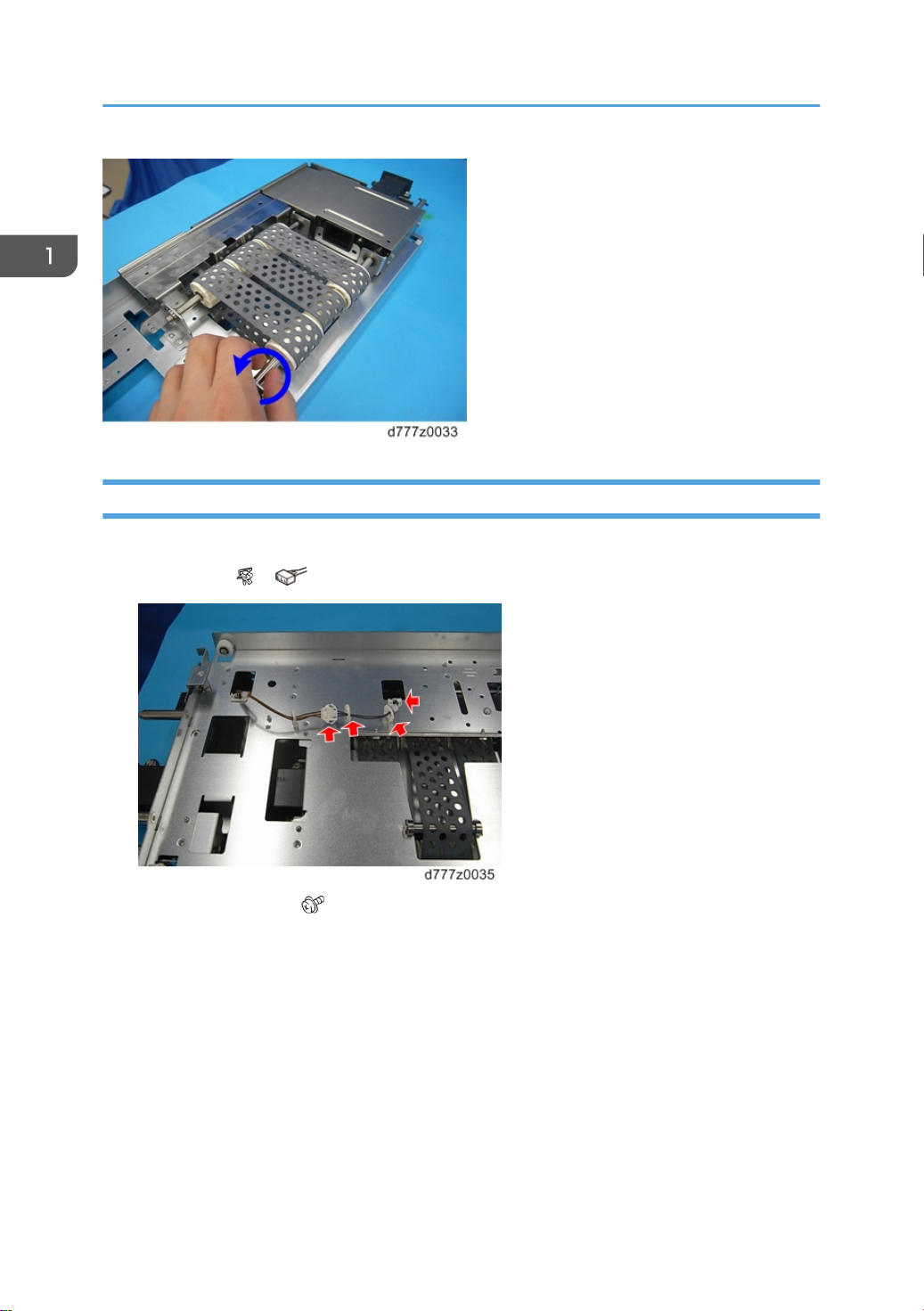
4. Turn the wire pick-up roller [A] at the rear of the paper tray in a clock-wise direction to raise the
bottom plate until it becomes visible on the end fence side.
35
Page 38

1. Replacement and Adjustment
5. When the bottom plate has been raised, insert a screwdriver or similar object in the hole in the
sheet metal at the bottom of the wire pick-up roller to prevent the pin [A] from turning.
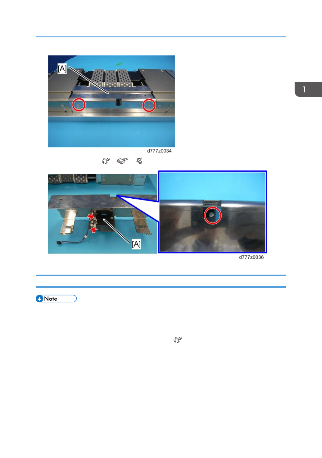
6. Remove the side fence guide [A] from the front side ( x2).
36
7. Remove the side fence guide [A] from the rear side ( x2).
Page 39

8. Two bottom plates [A] ( x4)
Paper Feed Unit (Trays 1, 2)
9. Remove the plate [A] from the paper feed side ( x2). There is a bracket [B] at the front side.
10. Fully close the side fence.
37
Page 40

1. Replacement and Adjustment
Side Fence (Front)
1. Do the common procedure for removing the side fences (Front, Rear). (page 35 "Common
Procedure for Removing the Side Fences (Front, Rear)")
2. Remove the side fence shafts [A] and [B] on the front side ( x2). Pull out the shaft in the direction of
the arrow. The [B] shaft has a spring.
38
3. Insert a screwdriver in the opening in the frame and remove the ground connection ( x1).
Page 41

4. Remove the screws in the side fence ( x4).
Paper Feed Unit (Trays 1, 2)
5. Clamp ( x2)
6. Hold down the lock lever [A] and raise the side fence [B].
39
Page 42

1. Replacement and Adjustment
7. Remove the connector from the bottom of the side fence ( x3, x2).
40
8. Raise the side fence (front) [A] and remove it.
9. Install the spring on the end face shaft as shown in the photo.
Page 43

Paper Feed Unit (Trays 1, 2)
Side Fence (Rear)
1. Do the common procedure for removing the side fences (Front, Rear). (page 35 "Common
Procedure for Removing the Side Fences (Front, Rear)")
2. Bracket [A] (
x1)
3. Remove the side fence shafts [A] and [B] on the rear side ( x2). Pull out the shaft in the direction of
the arrow. The [B] shaft has a spring.
41
Page 44

1. Replacement and Adjustment
4. Insert a screwdriver in the opening in the frame and remove the ground connection ( x1).
5. Remove the screws in the side fence ( x4).
42
Page 45

6. Clamp ( x2).
Paper Feed Unit (Trays 1, 2)
7. Hold down the lock lever [A] and raise the side fence [B].
8. Remove the connector from the bottom of the side fence ( x4, x2).
43
Page 46

1. Replacement and Adjustment
9. Lift the side fence (rear) and remove it.
10. Install the spring on the end face shaft as shown in the photo.
Paper Size Sensors
1. Side fence (rear) (page 35 "Side Fences (Front, Rear)")
2. Sensor bracket [A] ( x2)
44
Page 47

Paper Feed Unit (Trays 1, 2)
3. Remove the paper size sensors [1] to [4] ( x4, x4). The sensors are located in order 1 to 4 on
the paper feed side.
Side Fan
1. Side fence (page 35 "Side Fences (Front, Rear)")
2. Fan cover [A] ( x2)
45
Page 48

1. Replacement and Adjustment
3. Hold down the lock lever [A] and lower the plate [B] in the direction of the arrow.
46
4. Side fan [A] ( x2, x1)
Page 49

Side Fan Shutter Solenoid
1. Side fence (page 35 "Side Fences (Front, Rear)")
2. Bracket [A] ( x2)
3. Side fan shutter solenoid [A] ( x2)
Paper Feed Unit (Trays 1, 2)
47
Page 50

1. Replacement and Adjustment
Rear Side
• Do not pull out all the trays in the vacuum Feed LCIT RT5100 (when not linked to the main unit)
because it could fall over.
Main Board
1. Remove the rear right and left covers (page 8 "Rear Right Cover",page 8 "Rear Left Cover").
2. Main board ( x7, hook x1, all connectors and clamps)
Tray 1 Pickup Belt Motor
1. Remove the rear right and left covers (page 8 "Rear Right Cover",page 8 "Rear Left Cover").
2. Tray 1 grip motor bracket [A] ( x4, x2)
48
Page 51

3. Tray 1 pickup belt motor [A] ( x2)
Rear Side
• Do not remove the damper [A] between the motor and the bracket. This damper is factory installed
and cannot be adjusted outside the factory.
Re-installation
When installing the pickup belt motor, make sure that the motor is correctly placed on the timing belt [A].
49
Page 52

1. Replacement and Adjustment
Tray 1 Grip Motor
1. Remove the rear right and left covers (page 8 "Rear Right Cover", page 8 "Rear Left Cover").
2. Tray 1 grip motor bracket [A] ( x4, x2)
50
3. Tray 1 grip motor [A] ( x2)
Page 53

Rear Side
• Do not remove the damper [A] between the motor and the bracket. This damper is factory installed
and cannot be adjusted outside the factory.
Re-installation
When installing the grip motor, make sure that the motor is correctly placed on the timing belt [A].
Tray 2 Pickup Belt Motor
1. Remove the rear right and left covers (page 8 "Rear Right Cover", page 8 "Rear Left Cover").
2. Tray 2 grip motor bracket [A] ( x4, x2)
51
Page 54

1. Replacement and Adjustment
3. Tray 2 pickup belt motor (page 48 "Tray 1 Pickup Belt Motor")
• The procedure for removing and installing the tray 2 pickup belt motor is the same as for the
tray 1 pickup belt motor.
Tray 2 Grip Motor
1. Remove the rear right and left covers (page 8 "Rear Right Cover", page 8 "Rear Left Cover").
2. Tray 2 grip motor bracket [A] ( x4, x2)
3. Tray 2 grip motor (page 50 "Tray 1 Grip Motor")
• The procedure for removing and installing the tray 2 grip motor is the same as for the tray 1
grip motor.
52
Page 55

Suction Fan 1, 2 (Tray 1, 2)
• Suction fans 1, 2 can be removed using the same procedure for each tray. The following is the
procedure for replacing the fan in tray 1.
1. Remove the rear right and left covers (page 8 "Rear Right Cover", page 8 "Rear Left Cover").
Rear Side
2. Suction fan duct [A] (
3. Upper suction fan duct [A] ( x2)
x3, x4, x2)
4. Suction fan 1 [A] ( x2)
53
Page 56

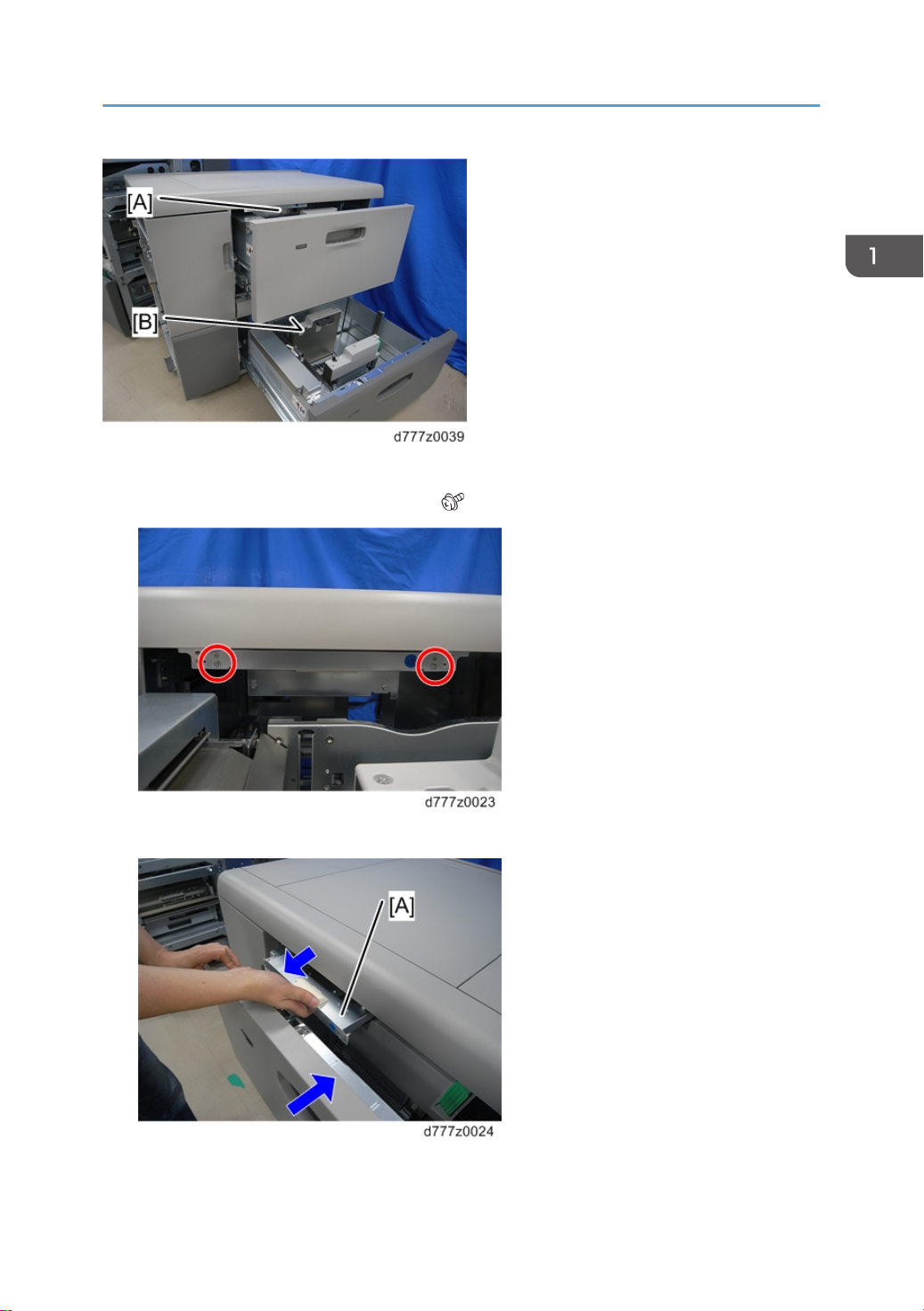
1. Replacement and Adjustment
5. Disassemble the suction fan 2 [A], the suction fan duct [B] and the bracket [C].
LCIT Lift Motor (Tray 1, 2)
• The LCIT lift motor can be removed using the same procedure for each tray. The following is the
procedure for replacing the motor in tray 1.
1. Remove the rear right and left covers (page 8 "Rear Right Cover", page 8 "Rear Left Cover").
2. Lift motor bracket [A] ( x2, x1)
54
Page 57

3. Lift motor [A] ( x3)
Bypass Transport Motor 2
• The bypass transport motor 1 is located on the side of the optional bypass unit. When an optional
bypass unit is not installed in the main unit, this motor is not used.
Rear Side
1. Remove the rear right and left covers (page 8 "Rear Right Cover", page 8 "Rear Left Cover").
2. Bypass transport motor 2 bracket [A] ( x2, x1)
3. Bypass transport motor 2[A] ( x2)
55
Page 58

1. Replacement and Adjustment
Re-installation
1. When attaching the bracket to the motor, position the bracket so that the opening in the bracket [A]
faces the label [B].
56
2. When attaching the motor bracket, turn the roller [A] to make sure that the timing belt [B] is
correctly installed.
Page 59

• If the timing belt is not correctly installed on the motor gear [A], the timing belt [B] may be too
loose.
Transport Motor Cooling Fan
1. Remove the rear right and left covers (page 8 "Rear Right Cover", page 8 "Rear Left Cover").
Rear Side
2. Remove the transport motor cooling fan [A] with the bracket ( x2, x2, x1).
3. Transport motor cooling fan [A] ( x2)
57
Page 60

1. Replacement and Adjustment
Re-installation
Install the transport motor cooling fan so that its label faces to the lower.
58
Page 61

Vertical Feed Unit
Vertical Feed Unit
• Do not pull out all the trays in the vacuum Feed LCIT RT510 (when not linked to the main unit)
because it could fall over.
Vertical Feed Unit
1. Upper inner cover (page 13 "Upper Inner Cover")
2. Lower inner cover (page 15 "Lower Inner Cover")
3. Remove the rear right and left covers (page 8 "Rear Right Cover", page 8 "Rear Left Cover").
4. Remove each vertical transport unit cooling fan bracket. (xref Vertical Transport Unit Cooling Fan)
5. Vertical transport exit motor bracket (page 72 "Vertical Transport Exit Motor")
6. Tray 2 vertical transport motor 2 bracket (page 68 "Tray 2 Vertical Transport Motor 2")
7. Disconnect all the harnesses that connected to the vertical feed unit ( x all, x all).
59
Page 62

1. Replacement and Adjustment
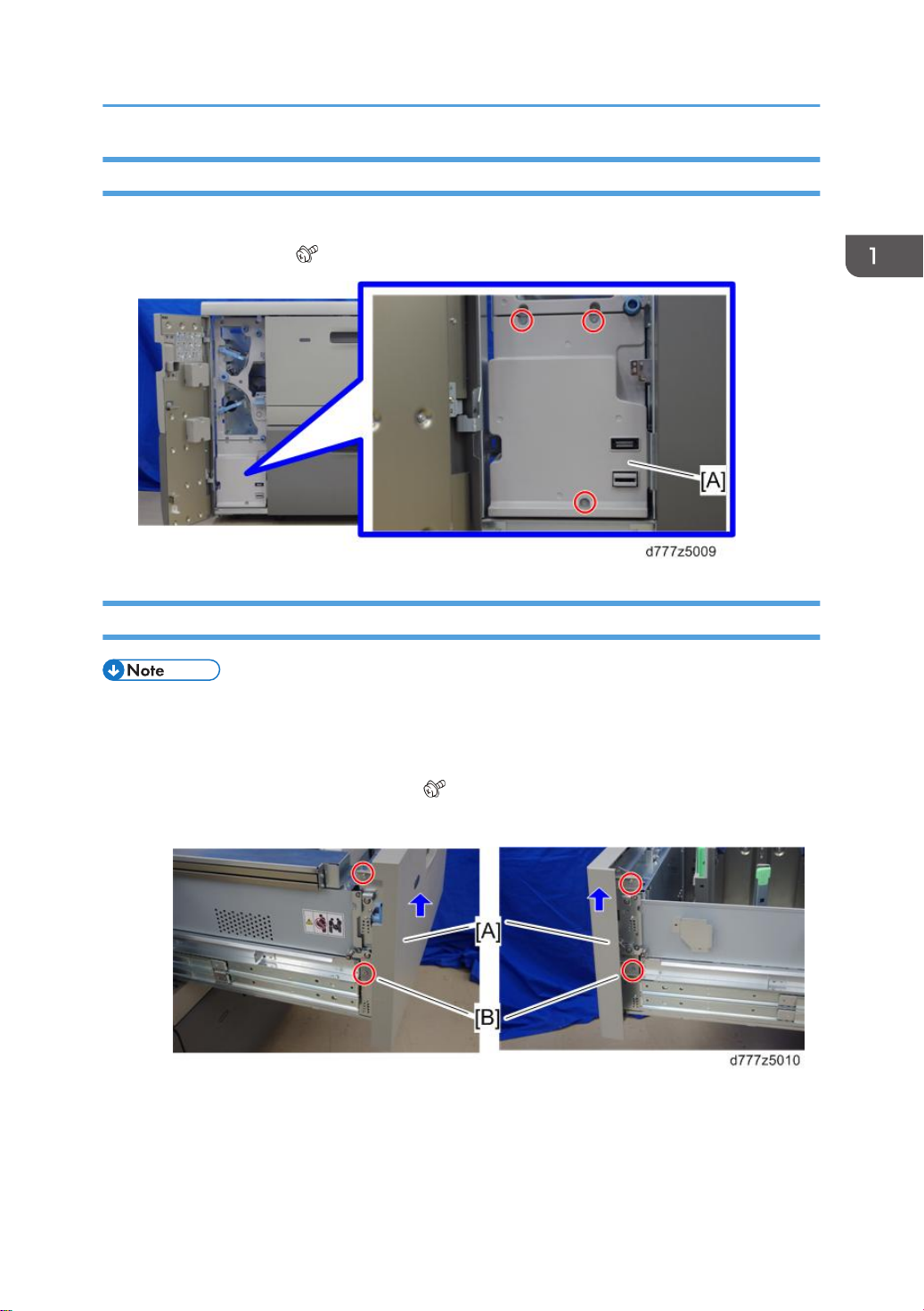
8. Remove the stay [A] from the left side ( x4).
9. Remove the six screws that secure the vertical feed unit [B] to the vacuum feed LCIT ( x6).
10. If linked to the vacuum feed LCIT, remove the horizontal feed unit ( x4).
60
Page 63

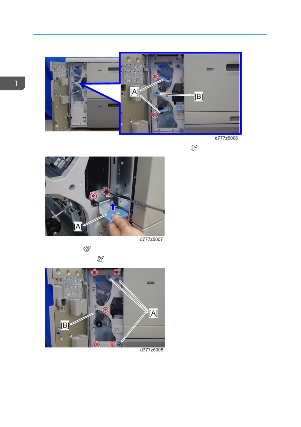
11. If linked to the vacuum feed LCIT, remove the paper jam processing lever [A] ( x2).
Vertical Feed Unit
12. Use both hands to support the vertical feed unit, raise it slightly and pull it towards you.
61
Page 64

1. Replacement and Adjustment
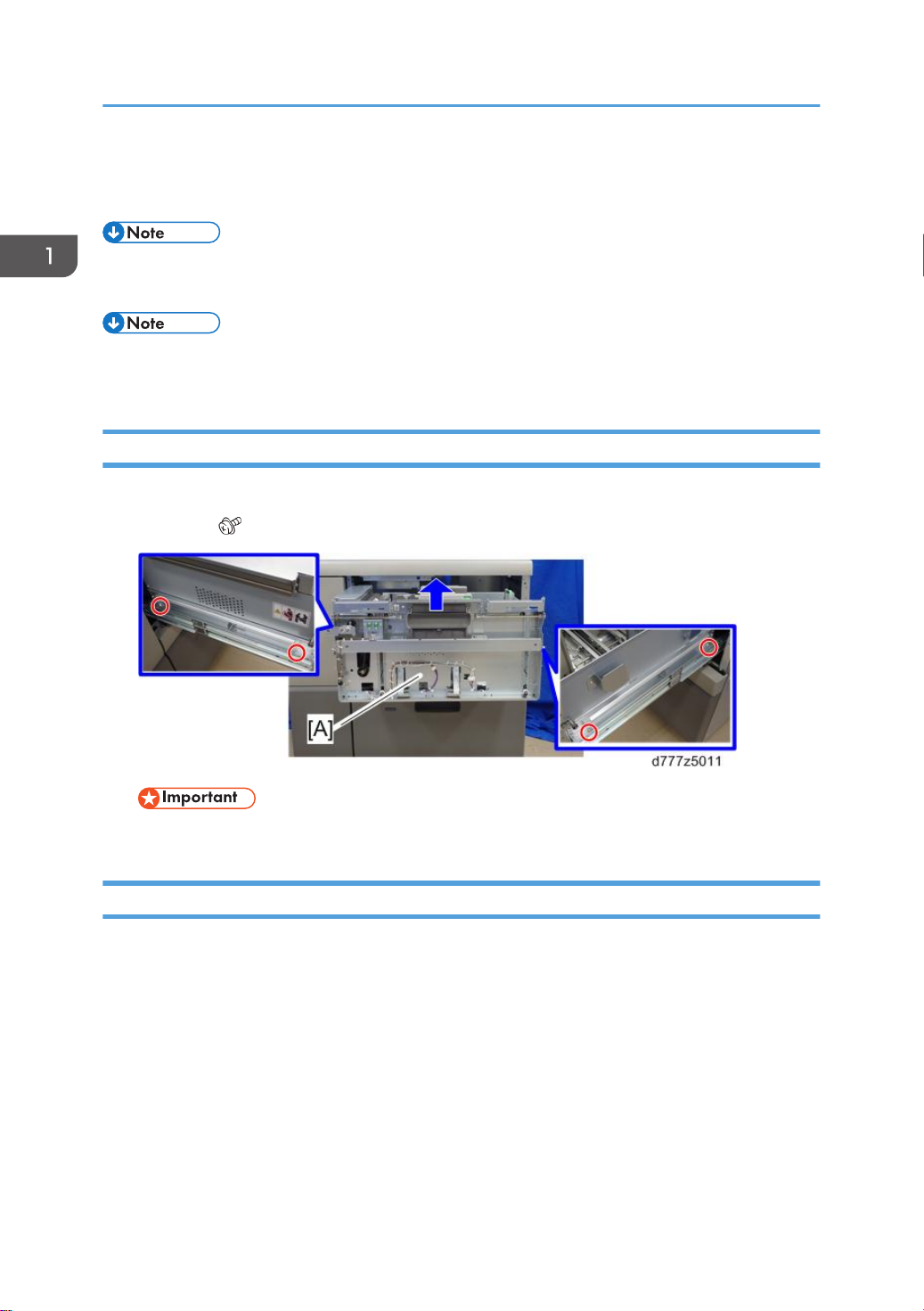
13. Place the vertical feed unit on the PSU box [A] and pull it out gently.
Re-installation
When installing the vertical feed unit, place the notches [B] on the right side of the frame of the vertical
feed unit on the two shoulder screws [A] on the left side of the LCIT.
62
Page 65

Vertical Feed Unit
Tray 1 Vertical Transport Motor 1
1. Remove the rear right and left covers (page 8 "Rear Right Cover", page 8 "Rear Left Cover").
2. Tray 1 vertical transport motor 1 bracket [A] ( x2, x1)
3. Tray 1 vertical transport motor 1[A] ( x2)
• When installing the motor, refer to re-installation for the bypass transport motor 2 (page 55
"Bypass Transport Motor 2").
Tray 1 Vertical Transport Motor 2
1. Remove the rear right and left covers (page 8 "Rear Right Cover", page 8 "Rear Left Cover").
2. Tray 1 vertical transport motor 2 bracket [A] ( x2, x1)
63
Page 66

1. Replacement and Adjustment
3. Tray 1 vertical transport motor 2 [A] ( x2)
• When installing the motor, refer to re-installation for the bypass transport motor 2 (page 55
"Bypass Transport Motor 2").
Tray 1 Transport Sensor
1. Vertical feed unit (page 59 "Vertical Feed Unit")
2. Shoulder screw [A]
64
Page 67

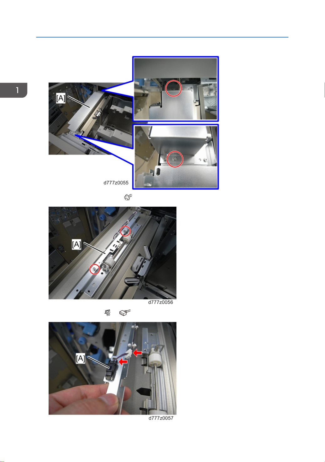
3. Remove the right cover [A] from the vertical feed unit ( x5).
Vertical Feed Unit
4. Tray 1 transport sensor bracket [A] ( x2)
5. Tray 1 transport sensor [A] ( x1, x1)
65
Page 68

1. Replacement and Adjustment
Tray 1 Vertical Transport Sensor
1. Vertical feed unit (page 59 "Vertical Feed Unit")
2. Remove the right cover [A] from the vertical feed unit ( x5).
66
3. Tray 1 vertical transport sensor bracket [A] ( x2)
4. Tray 1 vertical transport sensor [A] ( x1, x1)
Page 69

Vertical Feed Unit
Tray 2 Vertical Transport Motor 1
1. Remove the rear right and left covers (page 8 "Rear Right Cover", page 8 "Rear Left Cover").
2. Tray 2 vertical transport motor 1 bracket [A] ( x2, x1)
3. Tray 2 vertical transport motor 1 [A] ( x2)
67
Page 70

1. Replacement and Adjustment
• When installing the motor, refer to re-installation for the bypass transport motor 2 (page 55
"Bypass Transport Motor 2").
Tray 2 Vertical Transport Motor 2
1. Remove the rear right and left covers (page 8 "Rear Right Cover", page 8 "Rear Left Cover").
2. Tray 2 vertical transport motor 2 bracket [A] ( x3, x1)
3. Tray 2 vertical transport motor 2 [A] ( x2)
• Do not remove the damper [B] between the motor and the bracket. This damper is factory
installed and cannot be adjusted outside the factory.
Re-installation
1. When attaching the bracket to the motor, install it so that the connector openings [A] face the two
screw holes [B].
68
Page 71

Vertical Feed Unit
2. When attaching the motor bracket, turn the roller [A] to make sure that the timing belt [B] is
correctly installed.
Tray 2 Vertical Transport Sensor
1. Vertical feed unit (page 59 "Vertical Feed Unit")
2. Remove the right cover [A] from the vertical feed unit ( x5).
3. Tray 2 vertical transport sensor bracket [A] ( x2)
69
Page 72

1. Replacement and Adjustment
4. Tray 2 vertical transport sensor [A] ( x1, x1)
Tray 2 Transport Sensor
1. Vertical feed unit (page 59 "Vertical Feed Unit")
2. Remove the lower cover from the vertical transport unit [A] ( x4).
70
Page 73

Vertical Feed Unit
3. Bracket [A] ( x4)
4. Tray 2 transport sensor [A] ( x1, x1)
71
Page 74

1. Replacement and Adjustment
Vertical Transport Exit Motor
1. Remove the rear right and left covers (page 8 "Rear Right Cover", page 8 "Rear Left Cover").
2. Vertical transport exit motor bracket [A] ( x3, x1)
72
3. Vertical transport exit motor [A] ( x2)
• Do not remove the damper [B] between the motor and the bracket. This damper is factory
installed and cannot be adjusted outside the factory.
Page 75

Vertical Feed Unit
Re-installation
1. When attaching the bracket to the motor, install it so that the connector openings [A] face the two
screw holes [B].
2. When attaching the motor bracket, turn the roller [A] to make sure that the timing belt [B] is
correctly installed.
73
Page 76

1. Replacement and Adjustment
Bypass Transport Sensor 2
1. Vertical feed unit (page 59 "Vertical Feed Unit")
2. Bypass transport sensor 2 bracket [A] ( x2)
3. Bypass transport sensor 2 [A] ( x1, x1)
LCIT Exit Motor
1. Remove the rear right and left covers (page 8 "Rear Right Cover", page 8 "Rear Left Cover").
2. LCIT exit motor bracket [A] ( x2, x1)
3. LCIT exit motor [A] ( x2)
74
Page 77

Vertical Feed Unit
• When installing the motor, refer to re-installation for the bypass transport motor 2 (page 55
"Bypass Transport Motor 2").
LCIT Exit Roller Contact Motor
1. Remove the rear right and left covers (page 8 "Rear Right Cover", page 8 "Rear Left Cover").
2. LCIT exit roller contact motor bracket [A] ( x2, x1)
3. LCIT exit roller contact motor [A] ( x2)
75
Page 78

1. Replacement and Adjustment
Re-installation
1. When attaching the bracket to the motor, position the bracket so that the opening in the bracket [A]
faces the label [B].
2. When attaching the motor bracket, turn the roller [A] to make sure that the timing belt [B] is
correctly installed.
LCIT Exit Sensor
1. Bracket [A] ( x1, x1)
76
Page 79

2. LCIT exit sensor 1 [A] ( x1)
Vertical Feed Unit
LCIT Exit Roller Contact Sensor
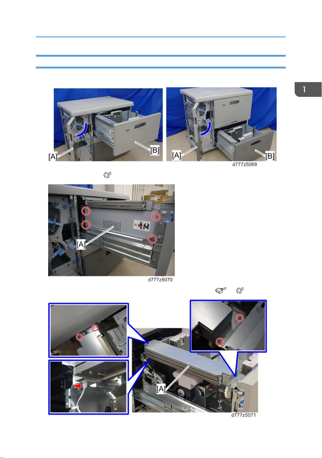
1. Remove the stay [A] from the vertical feed unit ( x2).
2. Bracket [A] ( x1, x1)
77
Page 80

1. Replacement and Adjustment
• The top stay is in the way. Use a small screwdriver to remove it.
3. LCIT exit roller contact sensor [A] ( x1, x1)
Vertical Transport Unit Cooling Fan
1. Remove the rear right and rear left covers (page 8 "Rear Right Cover", page 8 "Rear Left Cover").
2. Remove the vertical transport unit cooling fan [A] with the bracket ( x2, x1, x1).
78
Page 81

3. Vertical transport unit cooling fan [A] ( x2)
Vertical Feed Unit
Vertical Transport Unit Cooling Fan Re-installation
1. Install the cooling fan so that its label faces up
79
Page 82

1. Replacement and Adjustment
80
Page 83

PSU Box
PSU box
1. Remove the rear right and left covers (page 8 "Rear Right Cover", page 8 "Rear Left Cover").
2. Open the five clamps and disconnect the nine connectors [A]( x5, x9).
PSU Box
3. Pull out the PSU box [A] ( x5, x3, x2).
PSU1, 2
1. PSU box (page 81 "PSU box")
2. Open the six clamps.
81
Page 84

1. Replacement and Adjustment
3. Open the two clamps [A] in the PSU box and disconnect the connector [B].
82
4. Left PSU cover [A] ( x9, x2)
5. PSU2 [A] ( x8, x5)
Page 85

6. PSU1 [A] ( x8, x6)
PSU Box
PSU Cooling Fan 1, 2
1. PSU box (page 81 "PSU box")
2. Remove the PSU cooling fan 2 (cools PSU 1) [A] and PSU cooling fan 1 [B] (cools PSU 2) ( x4,
x2, x2).
83
Page 86

1. Replacement and Adjustment
Interlock Switch
1. Open the front door.
2. Lower inner cover (page 15 "Lower Inner Cover")
3. Bracket [A] ( x2)
4. Interlock switch [A] ( x1, x2)
84
Page 87

AC Drive Board
1. PSU box (page 81 "PSU box")
2. Open the six clamps.
3. Open the two clamps [A] in the PSU box and disconnect the connector [B].
PSU Box
4. Left PSU cover [A] ( x9, x2)
5. AC drive board [A] ( x6, x2)
85
Page 88

1. Replacement and Adjustment
Fuses on the PSU and AC drive board that can be replaced.
86
Fuses
FU3: 10A, 250V
FU4: 10A, 250V
PSU1, 2
FU5: 10A, 250V
FU7: 10A, 250V
Page 89

Fuses
AC drive board FU100: 15A, 250V
PSU Box
87
Page 90

MEMO
88 EN
 Loading...