

Page 1

Model J-P3
(Machine Code: G106)
SERVICE MANUAL
Subject to change
20 February 2004
Page 2

!IMPORTANT SAFETY NOTICES
PREVENTION OF PHYSICAL INJURY
1. Before disassembling or assembling parts of the printer and peripherals,
make sure that the printer power cord is unplugged.
2. The wall outlet should be near the printer and easily accessible.
3. If any adjustment or operation check has to be made with exterior covers off
or open while the main switch is turned on, keep hands away from electrified
or mechanically driven components.
4. The printer drives some of its components when it completes the warm-up
period. Be careful to keep hands away from the mechanical and electrical
components as the printer starts operation.
5. The inside and the metal parts of the fusing unit become extremely hot while
the printer is operating. Be careful to avoid touching those components with
your bare hands.
HEALTH SAFETY CONDITIONS
Toner and developer are non-toxic, but if you get either of them in your eyes by
accident, it may cause temporary eye discomfort. Try to remove with eye drops
or flush with water as first aid. If unsuccessful, get medical attention.
OBSERVANCE OF ELECTRICAL SAFETY STANDARDS
1. The printer and its peripherals must be serviced by a customer service
representative who has completed the training course on those models.
2. The NVRAM module (option) installed on the controller has a lithium battery
which can explode if replaced incorrectly. Replace the NVRAM only with an
identical one. The manufacturer recommends replacing the entire NVRAM.
Do not recharge or burn this battery. Used NVRAM must be handled in
accordance with local regulations.
3. The optional fax and memory expansion units contain lithium batteries,
which can explode if replaced incorrectly. Replace only with the same or an
equivalent type recommended by the manufacturer. Do not recharge or burn
the batteries. Used batteries must be handled in accordance with local
regulations.
Page 3
SAFETY AND ECOLOGICAL NOTES FOR DISPOSAL
1. Do not incinerate toner bottles or used toner. Toner dust may ignite suddenly
when exposed to an open flame.
2. Dispose of used toner, the maintenance unit which includes developer or the
organic photoconductor in accordance with local regulations. (These are
non-toxic supplies.)
3. Dispose of replaced parts in accordance with local regulations.
4. When keeping used lithium batteries in order to dispose of them later, do not
put more than 100 batteries per sealed box. Storing larger numbers or not
sealing them apart may lead to chemical reactions and heat build-up.
5. Dispose of used fusing oil in accordance with local regulations.
LASER SAFETY
The Center for Devices and Radiological Health (CDRH) prohibits the repair of
laser-based optical units in the field. The optical housing unit can only be repaired
in a factory or at a location with the requisite equipment. The laser subsystem is
replaceable in the field by a qualified Customer Engineer. The laser chassis is not
repairable in the field. Customer engineers are therefore directed to return all
chassis and laser subsystems to the factory or service depot when replacement of
the optical subsystem is required.
!WARNING
Use of controls, or adjustment, or performance of procedures other than
those specified in this manual may result in hazardous radiation exposure.
!WARNING
WARNING: Turn off the main switch before attempting any of the
procedures in the Laser Optics Housing Unit section. Laser
beams can seriously damage your eyes.
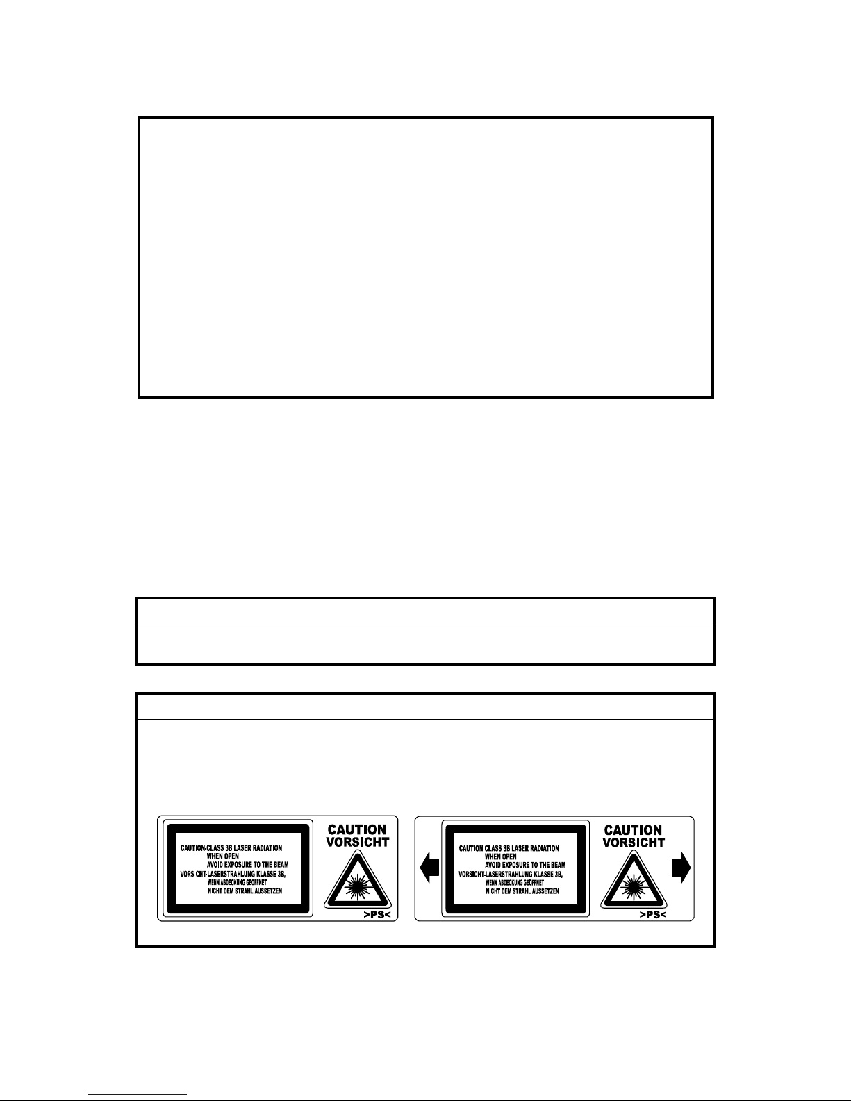
CAUTION MARKING:
Page 4

Trademarks
Microsoft
®
, Windows®, and MS-DOS® are registered trademarks of Microsoft
Corporation in the United States and /or other countries.
PostScript
®
is a registered trademark of Adobe Systems, Incorporated.
PCL
®
is a registered trademark of Hewlett-Packard Company.
Ethernet
®
is a registered trademark of Xerox Corporation.
PowerPC
®
is a registered trademark of International Business Machines
Corporation.
Other product names used herein are for identification purposes only and may be
trademarks of their respective companies. We disclaim any and all rights involved
with those marks.
Symbols and Abbreviations
This manual uses the symbols and abbreviations shown below.
Symbol Meaning
☛
Refer to section number
!
Clip ring
"
Screw
#
Connector
SEF Short Edge Feed
LEF Long Edge Feed
Long Edge Feed (LEF)Short Edge Feed (SEF)
Page 5

i
TABLE OF CONTENTS
1. INSTALLATION........................................................................... 1-1
1.1 INSTALLATION REQUIREMENTS........................................................... 1-1
1.1.1 ENVIRONMENT .............................................................................. 1-1
1.1.2 MACHINE LEVEL ............................................................................ 1-1
1.1.3 MACHINE SPACE REQUIREMENT................................................ 1-2
Printer .................................................................................................. 1-2
Printer and Finisher.............................................................................. 1-2
1.1.4 POWER REQUIREMENTS.............................................................. 1-3
1.2 OPTIONAL UNIT COMBINATIONS.......................................................... 1-4
1.3 PRINTER.................................................................................................. 1-5
1.3.1 POWER SOCKETS FOR PERIPHERALS....................................... 1-5
1.3.2 INSTALLATION FLOW CHART....................................................... 1-6
1.3.3 INSTALLATION AND SETTINGS.................................................... 1-7
1.3.4 MOVING THE MACHINE................................................................. 1-8
1.3.5 TRANSPORTING THE MACHINE................................................... 1-9
After Machine Test............................................................................... 1-9
Transporting Used Machine................................................................. 1-9
Necessary Adjustment ......................................................................... 1-9
Preparing the Printer.......................................................................... 1-10
1.4 OPTIONAL UNIT .................................................................................... 1-12
1.4.1 TWO-TRAY FINISHER.................................................................. 1-12
Accessory Check ............................................................................... 1-12
Installation Procedure ........................................................................ 1-12
1.4.2 PUNCH UNIT................................................................................. 1-18
Accessory Check ............................................................................... 1-18
Installation Procedure ........................................................................ 1-19
1.4.3 BOOKLET FINISHER .................................................................... 1-22
Accessory Check ............................................................................... 1-22
Adjusting the Height........................................................................... 1-23
Main Body .......................................................................................... 1-24
1.4.4 OPTIONAL PUNCH UNIT.............................................................. 1-27
Accessory Check ............................................................................... 1-27
Installation Procedure ........................................................................ 1-27
2. PREVENTIVE MAINTENANCE................................................... 2-1
2.1 USER MAINTENANCE............................................................................. 2-1
Maintenance Kit ................................................................................... 2-1
PM Alert Display................................................................................... 2-1
New Unit Detection .............................................................................. 2-1
PM Table.............................................................................................. 2-2
2.2 SERVICE MAINTENANCE....................................................................... 2-3
PM Counter Reset................................................................................ 2-3
PM Table.............................................................................................. 2-3
Page 6

ii
3. REPLACEMENT AND ADJUSTMENT........................................ 3-1
3.1 MODEL J-P3 AND MODEL J-P2.............................................................. 3-1
3.2 SPECIAL TOOLS ..................................................................................... 3-1
3.3 LASER OPTICS........................................................................................ 3-2
3.3.1 CAUTION DECAL LOCATIONS ...................................................... 3-2
3.3.2 LASER OPTICS HOUSING UNIT.................................................... 3-3
3.3.3 POLYGON MIRROR MOTOR ......................................................... 3-7
3.3.4 POLYGON MIRROR MOTOR DRIVE BOARD................................ 3-8
3.3.5 LASER SYNCHRONIZING DETECTOR BOARDS ......................... 3-8
3.4 PAPER FEED........................................................................................... 3-9
3.4.1 REGISTRATION SENSOR AND RELAY SENSORS ...................... 3-9
3.4.2 BY-PASS FEED CLUTCH ............................................................. 3-10
3.4.3 PAPER FEED MOTOR.................................................................. 3-10
3.5 TRANSFER AND PAPER TRANSPORT UNIT ...................................... 3-11
3.5.1 TRANSFER UNIT .......................................................................... 3-11
3.5.2 TRANSFER BELT CLEANING UNIT............................................. 3-12
3.5.3 CLEANING BLADE AND CLEANING ROLLER............................. 3-12
3.5.4 TRANSFER UNIT DRIVE MOTOR................................................ 3-14
3.6 ID SENSORS.......................................................................................... 3-15
3.7 FUSING .................................................................................................. 3-16
3.7.1 CLEANING UNIT ........................................................................... 3-16
3.7.2 PRESSURE ROLLER.................................................................... 3-17
3.7.3 FUSING UNIT FAN........................................................................ 3-19
3.8 ELECTRICAL COMPONENTS............................................................... 3-20
3.8.1 CONTROLLER AND BCU ............................................................. 3-20
3.8.2 NVRAM REPLACEMENT PROCEDURE ...................................... 3-22
NVRAM on the BCU........................................................................... 3-22
NVRAM on the Controller................................................................... 3-23
NVRAMs on the BCU and Controller ................................................. 3-24
3.8.3 HIGH VOLTAGE SUPPLY BOARD ............................................... 3-25
3.8.4 CIRCUIT BREAKER AND PSU FAN ............................................. 3-26
3.8.5 CHOKE COIL................................................................................. 3-26
3.8.6 DEVELOPMENT DRIVE MOTOR-K.............................................. 3-27
3.8.7 WASTE TONER VIBRATOR ......................................................... 3-28
4. TROUBLESHOOTING................................................................. 4-1
4.1 MODEL J-P3 AND MODEL J-P2.............................................................. 4-1
4.2 PROCESS CONTROL ERROR CONDITIONS ........................................ 4-1
4.2.1 DEVELOPER INITIALIZATION RESULT......................................... 4-1
4.2.2 PROCESS CONTROL SELF-CHECK RESULT .............................. 4-2
4.2.3 LINE POSITION ADJUSTMENT RESULT....................................... 4-3
SC Code Classification ........................................................................ 4-4
4.3 SC TABLE ................................................................................................ 4-5
4.4 TROUBLESHOOTING GUIDE ............................................................... 4-15
4.4.1 IMAGE QUALITY........................................................................... 4-15
4.4.2 COLOR SHIFT............................................................................... 4-16
Adjustment Standard.......................................................................... 4-18
Preparation......................................................................................... 4-18
Page 7

iii
4.4.3 BLACK OVER PRINT .................................................................... 4-20
Black Over Print Enabled................................................................... 4-20
Black Over Print Disabled .................................................................. 4-20
4.5 BLOWN FUSE CONDITIONS................................................................. 4-21
Main PSU........................................................................................... 4-21
Sub PSU ............................................................................................ 4-21
BCU ................................................................................................... 4-21
4.6 LEDS (BCU) ........................................................................................... 4-22
5. SERVICE TABLES...................................................................... 5-1
5.1 SERVICE PROGRAM MODE................................................................... 5-1
5.1.1 HANDLING SERVICE PROGRAM MODE....................................... 5-1
Starting SP Mode................................................................................. 5-1
Selecting a Service Program................................................................ 5-2
Changing a Setting............................................................................... 5-2
Quitting SP Mode................................................................................. 5-2
Enabling Settings ................................................................................. 5-2
Line Position Adjustment...................................................................... 5-2
5.1.2 REMARKS ....................................................................................... 5-3
Abbreviations and Symbols.................................................................. 5-3
Possible Values.................................................................................... 5-3
Process Speed..................................................................................... 5-4
5.2 CONTROLLER SERVICE MODE............................................................. 5-5
5.2.1 SERVICE MODE TABLE................................................................. 5-5
5.2.2 BIT SWITCH PROGRAMMING ....................................................... 5-7
5.3 ENGINE SERVICE MODE........................................................................ 5-8
5.3.1 SERVICE MODE TABLE................................................................. 5-8
SP1-XXX (Feed) .................................................................................. 5-8
SP2-XXX (Drum)................................................................................ 5-15
SP3-XXX (Process)............................................................................ 5-26
SP5-XXX (Mode)................................................................................ 5-33
SP6-XXX (Peripherals) ...................................................................... 5-47
SP7-XXX (Data Log) .......................................................................... 5-48
SP8-XXX (Data Log 2) ....................................................................... 5-55
5.3.2 MEMORY CLEAR/COUNTER CLEAR .......................................... 5-65
5.3.3 INPUT CHECK TABLE .................................................................. 5-66
Table 1: Paper Height Sensor............................................................ 5-68
Table 2: Paper Size Switch (Tray 2)................................................... 5-68
Table 3: Paper Size (By-pass Table) ................................................. 5-69
5.3.4 OUTPUT CHECK TABLE .............................................................. 5-70
5.3.5 TEST PATTERN (SP5-997)........................................................... 5-74
5.4 FIRMWARE UPDATE............................................................................. 5-75
5.4.1 TYPE OF FIRMWARE................................................................... 5-75
5.4.2 PRECAUTIONS............................................................................. 5-75
Handling SD Cards ............................................................................ 5-75
Upload or Download........................................................................... 5-75
Network Connection........................................................................... 5-75
Page 8

i
v
5.4.3 FILE ARRANGEMENT .................................................................. 5-76
How the Program Works .................................................................... 5-76
Example ............................................................................................. 5-76
5.4.4 UPDATING .................................................................................... 5-77
Procedure........................................................................................... 5-77
Error Handling.................................................................................... 5-78
Power Failure..................................................................................... 5-78
5.4.5 NVRAM DATA UPLOAD/DOWNLOAD.......................................... 5-79
Uploading NVRAM Data .................................................................... 5-79
Downloading NVRAM Data................................................................ 5-80
5.4.6 ERROR CODE TABLE .................................................................. 5-81
5.5 SD CARD APPLI MOVE......................................................................... 5-82
5.5.1 OVERVIEW.................................................................................... 5-82
5.5.2 MOVE EXEC.................................................................................. 5-83
5.5.3 UNDO EXEC.................................................................................. 5-84
5.6 CONTROLLER SELF-DIAGNOSTICS.................................................... 5-85
5.6.1 OVERVIEW.................................................................................... 5-85
5.6.2 DETAILED SELF-DIAGNOSTICS.................................................. 5-86
5.7 USER PROGRAM MODE....................................................................... 5-87
Starting a User Program .................................................................... 5-87
Quitting a User Program .................................................................... 5-87
Menu List ........................................................................................... 5-87
5.8 DIP SWITCHES...................................................................................... 5-88
Controller Board................................................................................. 5-88
BCU Board......................................................................................... 5-88
6. DETAILED DESCRIPTIONS ....................................................... 6-1
6.1 MODEL J-P3 AND MODEL J-P2.............................................................. 6-1
6.2 OVERVIEW .............................................................................................. 6-2
6.2.1 COMPONENT LAYOUT .................................................................. 6-2
6.2.2 DRIVE LAYOUT............................................................................... 6-3
6.2.3 BOARD STRUCTURE ..................................................................... 6-4
Overview .............................................................................................. 6-4
Descriptions ......................................................................................... 6-5
6.3 LASER EXPOSURE ................................................................................. 6-7
6.3.1 OVERVIEW...................................................................................... 6-7
6.3.2 OPTICAL PATH............................................................................... 6-8
6.3.3 LD SAFETY SWITCH ...................................................................... 6-9
6.4 PHOTOCONDUCTOR UNIT .................................................................. 6-10
6.4.1 OVERVIEW.................................................................................... 6-10
6.4.2 DRUM CHARGE AND QUENCHING ............................................ 6-11
6.4.3 DRUM CLEANING......................................................................... 6-12
6.4.4 WASTE TONER COLLECTION..................................................... 6-13
Waste Toner Path .............................................................................. 6-13
Waste Toner Vibrator ......................................................................... 6-14
6.5 PAPER FEED LINE SPEED................................................................... 6-15
6.6 IMAGE TRANSFER AND PAPER SEPARATION .................................. 6-16
6.6.1 OVERVIEW.................................................................................... 6-16
Page 9

v
6.6.2 TRANSFER BELT DRIVE.............................................................. 6-17
Drive Motor......................................................................................... 6-17
Rotation Encoder ............................................................................... 6-18
ACS (Auto Color Sensing) Mode........................................................ 6-19
6.7 FUSING .................................................................................................. 6-20
6.7.1 FUSING TEMPERATURE CONTROL........................................... 6-20
Fusing Temperatures......................................................................... 6-20
Temperature Corrections ................................................................... 6-21
Overheat Protection ........................................................................... 6-21
6.7.2 ENERGY SAVER MODE............................................................... 6-22
Level 1 Energy Saver Mode............................................................... 6-22
Level 2 Energy Saver Mode............................................................... 6-22
6.8 CONTROLLER ....................................................................................... 6-23
6.8.1 OVERVIEW.................................................................................... 6-23
6.8.2 BOARD LAYOUT........................................................................... 6-24
6.8.3 CONTROLLER FUNCTIONS......................................................... 6-25
Paper Output Tray.............................................................................. 6-25
Stapling .............................................................................................. 6-25
Punching ............................................................................................ 6-26
6.9 HARD DISK ............................................................................................ 6-27
PERIPHERALS
BOOKLET FINISHER (B602)
1. REPLACEMENT AND ADJUSTMENT..................................B602-1
1.1 REGULAR TRAY................................................................................ B602-1
1.2 COVERS............................................................................................. B602-1
1.2.1 FRONT COVER......................................................................... B602-1
1.2.2 REAR COVER ........................................................................... B602-3
1.2.3 LEFT/RIGHT TOP AND TRAY UPPER COVER........................ B602-3
1.2.4 UPPER RIGHT COVER............................................................. B602-5
1.3 SIDE GUIDE ....................................................................................... B602-6
Removal......................................................................................... B602-6
Reassembly ................................................................................... B602-6
1.4 STAPLER UNIT .................................................................................. B602-7
Removal......................................................................................... B602-7
Adjusting the Stapler Gear Phase................................................ B602-10
1.5 FOLDING UNIT ................................................................................ B602-13
Removal....................................................................................... B602-13
Adjusting the Folding Unit Gear Phase ........................................ B602-15
1.6 STACK TRAY AND JOGGER FENCE.............................................. B602-16
1.6.1 STACK TRAY UNIT................................................................. B602-16
1.6.2 JOGGER FENCE UNIT ........................................................... B602-18
1.7 STAPLER MOTOR UNIT.................................................................. B602-20
1.8 TRANSPORT.................................................................................... B602-22
1.8.1 TRANSPORT MOTOR ............................................................B602-22
Page 10

vi
1.8.2 TRANSPORT ROLLER ........................................................... B602-22
1.9 STACK TRAY ................................................................................... B602-24
1.9.1 STACK TRAY UPPER ROLLER.............................................. B602-24
1.9.2 STACK TRAY PADDLE........................................................... B602-25
1.9.3 STACK TRAY LOWER ROLLER ............................................. B602-27
Removal....................................................................................... B602-27
Reassembly ................................................................................. B602-29
1.10 CIRCUIT BOARD............................................................................ B602-30
1.10.1 CONTROLLER BOARD......................................................... B602-30
1.10.2 STAPLER HOME POSITION SENSOR BOARD ................... B602-30
1.11 PUNCH UNIT, MOTORS, AND CONTROLLER ............................. B602-32
1.11.1 PUNCH UNIT AND PUNCH UNIT MOTOR........................... B602-32
1.11.2 REGISTRATION MOTOR...................................................... B602-34
1.11.3 CONTROLLER ...................................................................... B602-35
1.11.4 PHOTO SENSOR BOARD .................................................... B602-35
1.11.5 LED BOARD .......................................................................... B602-36
1.11.6 CHAD BOX FULL SENSOR BOARD AND LED BOARD ...... B602-37
1.11.7 ADJUSTMENT AND INITIALIZATION................................... B602-38
Sensor Voltage............................................................................. B602-38
Punch Type.................................................................................. B602-39
EEPROM...................................................................................... B602-39
2. SERVICE TABLES..............................................................B602-40
2.1 DIP SWITCH SETTINGS.................................................................. B602-40
Punch Controller Board................................................................ B602-40
3. DETAILED DESCRIPTIONS ...............................................B602-41
3.1 GENERAL LAYOUT ......................................................................... B602-41
3.2 DRIVE............................................................................................... B602-42
3.3 CONTROLLER ................................................................................. B602-43
3.4 STACK TRAY ................................................................................... B602-44
3.4.1 SIMPLE OUTPUT.................................................................... B602-44
Mechanism................................................................................... B602-44
Stack-Tray Belt............................................................................. B602-44
3.4.2 SORT....................................................................................... B602-45
3.4.3 STACK..................................................................................... B602-46
Paddle.......................................................................................... B602-46
Stack-Tray Stopper ...................................................................... B602-46
Stack-Tray Guide Mechanism...................................................... B602-47
Stack-Tray Guide Mechanism...................................................... B602-48
Home Position.............................................................................. B602-48
Stapler Switch .............................................................................. B602-48
Safety Feature.............................................................................. B602-48
3.4.4 JOGGER FENCE..................................................................... B602-49
Action ........................................................................................... B602-49
Drive............................................................................................. B602-49
Home Position.............................................................................. B602-49
Paper Position.............................................................................. B602-50
Page 11

vii
3.4.5 PAPER OUTPUT..................................................................... B602-51
Mechanism................................................................................... B602-51
Stack-Tray Belt Home Position .................................................... B602-51
3.5 STAPLING........................................................................................ B602-52
3.5.1 OVERVIEW.............................................................................. B602-52
3.5.2 STAPLER................................................................................. B602-53
Mechanism................................................................................... B602-53
Stapler Switch .............................................................................. B602-53
Sensors........................................................................................ B602-53
3.5.3 POSITIONING ......................................................................... B602-54
Action and Drive........................................................................... B602-54
Home Position and Ready Position.............................................. B602-54
Staple Position ............................................................................. B602-55
3.6 REGULAR TRAY.............................................................................. B602-57
Action and Drive........................................................................... B602-57
Ready Position............................................................................. B602-57
Paper Sensor ............................................................................... B602-58
Paper Full..................................................................................... B602-58
Fail Safe Feature.......................................................................... B602-58
3.7 SADDLE STITCH ............................................................................. B602-59
3.7.1 OVERVIEW.............................................................................. B602-59
3.7.2 STACK TRAY .......................................................................... B602-60
3.7.3 STAPLER................................................................................. B602-60
3.7.4 PAPER TRANSPORT.............................................................. B602-61
3.7.5 PAPER OUTPUT..................................................................... B602-62
Folding Plate Mechanism............................................................. B602-62
Folding Plate Home Position........................................................ B602-62
Folder Rollers Mechanism ........................................................... B602-63
Folder Rollers Home Position....................................................... B602-63
Shape of Folder Rollers ...............................................................B602-64
3.8 PUNCH UNIT (OPTIONAL) .............................................................. B602-65
3.8.1 REGISTRATION...................................................................... B602-65
Slide Unit...................................................................................... B602-65
Home Position.............................................................................. B602-65
Registration.................................................................................. B602-65
3.8.2 PUNCH .................................................................................... B602-67
Types of Punch Unit..................................................................... B602-67
Drive............................................................................................. B602-67
Home Position.............................................................................. B602-67
Two Holes and Four Holes........................................................... B602-68
Two or Three Holes...................................................................... B602-69
SPECIFICATIONS
1. GENERAL SPECIFICATIONS.............................................................SPEC-1
2. SUPPORTED PAPER SIZES..............................................................SPEC-3
2.1 PAPER FEED ..............................................................................SPEC-3
2.2 PAPER EXIT................................................................................SPEC-4
Page 12

viii
3. SOFTWARE ACCESSORIES..............................................................SPEC-5
3.1 PRINTER DRIVERS ....................................................................SPEC-5
3.2 UTILITY SOFTWARE ..................................................................SPEC-5
4. MACHINE CONFIGURATION .............................................................SPEC-6
Controller.......................................................................................SPEC-7
Others ...........................................................................................SPEC-7
5. OPTIONAL EQUIPMENT ....................................................................SPEC-8
5.1 500-SHEET TRAY .......................................................................SPEC-8
5.2 1000-SHEET TRAY .....................................................................SPEC-8
5.3 2000-SHEET LARGE CAPACITY TRAY .....................................SPEC-8
5.4 TWO-TRAY FINISHER & PUNCH UNIT......................................SPEC-9
5.5 BOOKLET FINISHER ................................................................SPEC-10
Page 13
20 February 2004 INSTALLATION REQUIREMENTS
1-1
Installation
1. INSTALLATION
1.1 INSTALLATION REQUIREMENTS
1.1.1 ENVIRONMENT
1. Temperature Range: 10°C to 32°C (50°F to 89.6°F)
2. Humidity Range: 15% to 80% RH
3. Ambient Illumination: Less than 2,000 lux (do not expose to direct sunlight)
4. Ventilation: 3 times/hr/person or more
5. Avoid exposing the machine to sudden temperature changes, which include:
1) Direct cool air from an air conditioner
2) Direct heat from a heater
6. Avoid installing the machine in areas that might be exposed to corrosive gas.
7. Install the machine at a location lower than 2,500 m (8,200 ft.) above sea level.
8. Install the machine on a strong, level base (☛ 1.1.2).
9. Avoid installing the machine in areas that may be subjected to strong vibration.
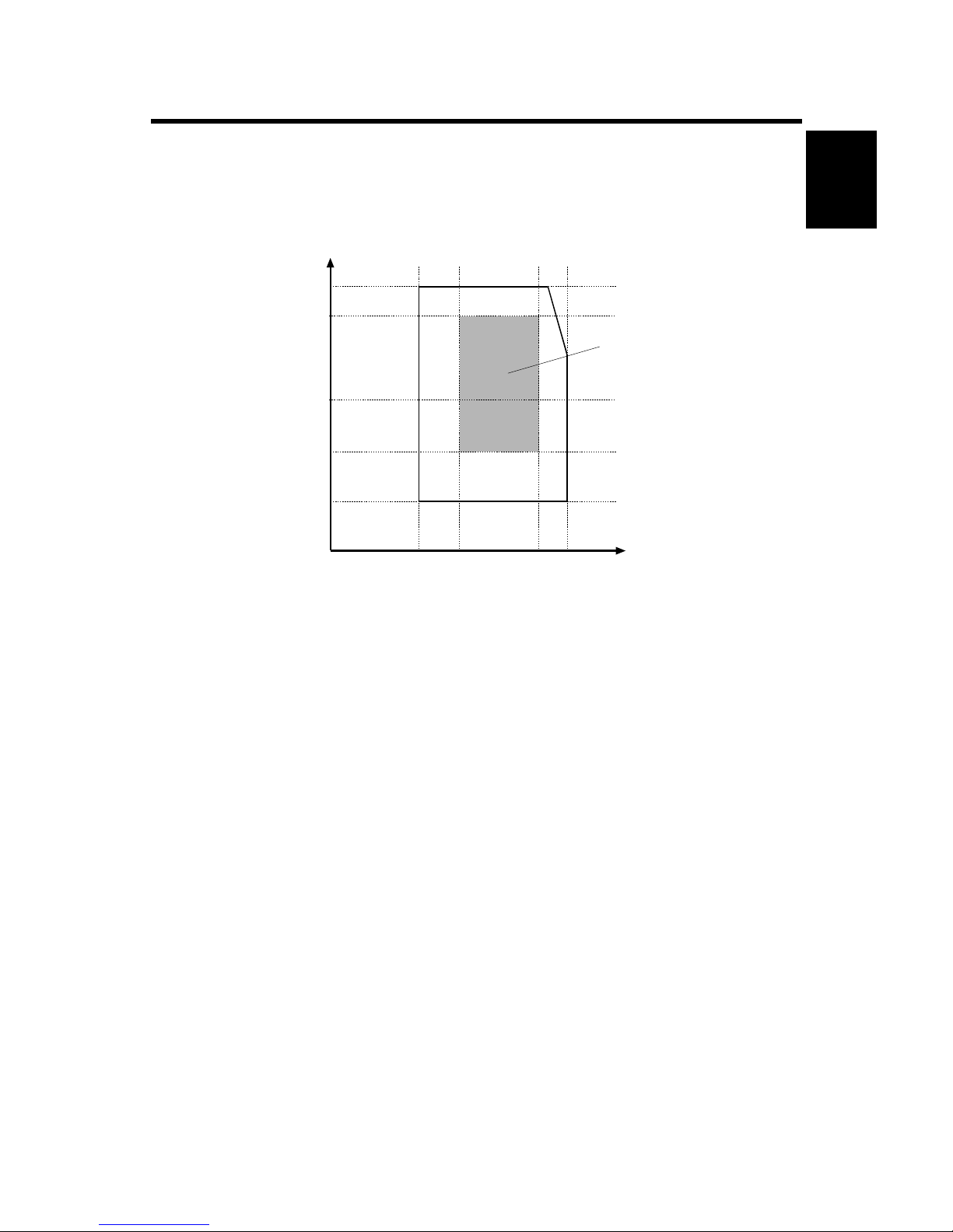
1.1.2 MACHINE LEVEL
Front to back: Within 5 mm (0.2")
Right to left: Within 5 mm (0.2")
G106I900.WMF
Ambient Humidity (%RH)
80%
70%
54%
30%
10°C 15°C25°C 32°C
15%
Recommended conditions:
15 to 25°C
30 to 70%RH
Page 14
INSTALLATION REQUIREMENTS 20 February 2004
1-2
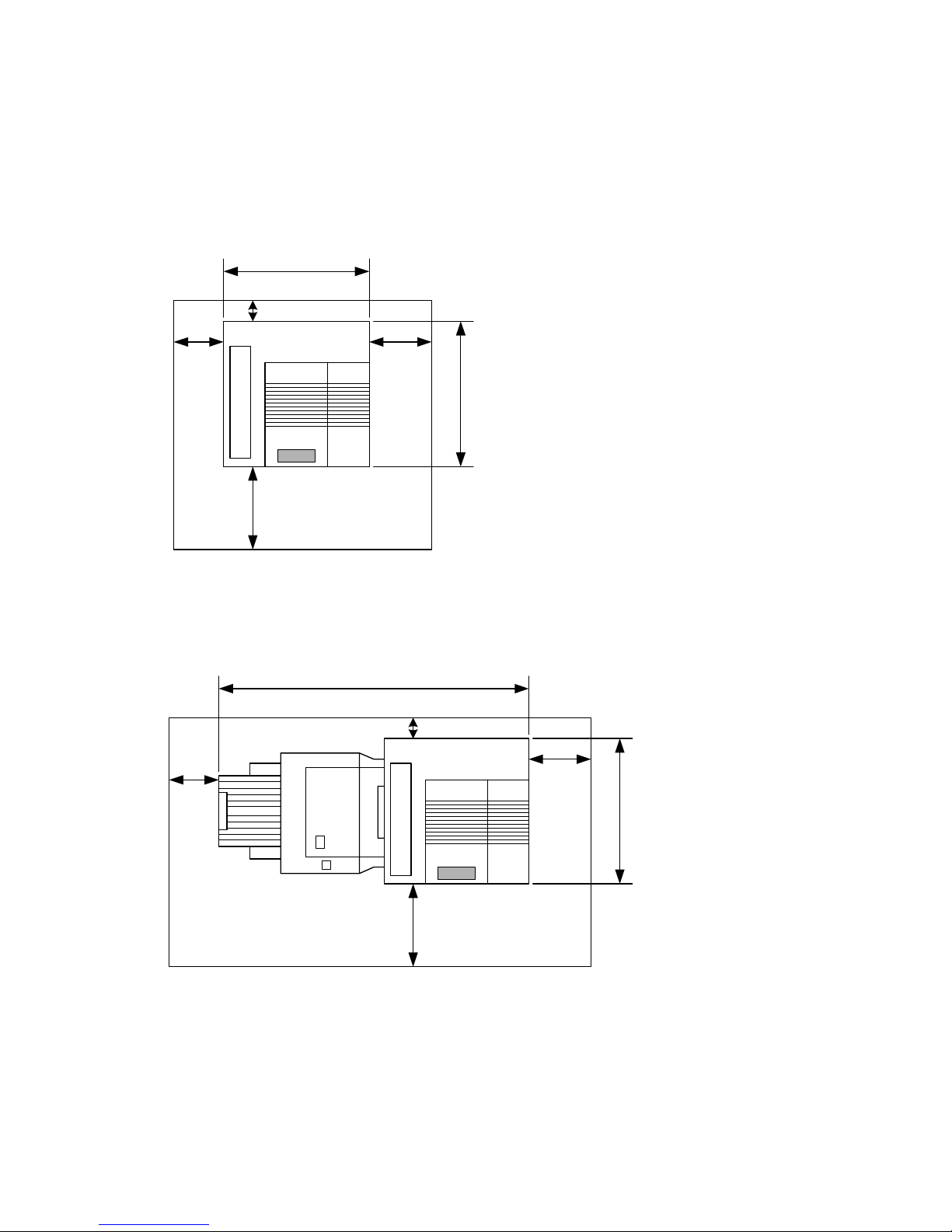
1.1.3 MACHINE SPACE REQUIREMENT
Install the machine near the power source. The diagrams show the necessary
space.
Printer
Printer and Finisher
[A]: Over 460 mm (18")
[B]: Over 100 mm (4")
[C]: Over 550 mm (22")
[D]: Over 700 mm (28")
!
!
!
!
!
!
!
!
!
!
!
!
B
D
C
A
575mm
678mm
G106I901.WMF
!
!
!
!
!
!
!
!
!
!
!
!
B
D
C
A
1450mm
678mm
!
!
G106I902.WMF
A
: Over 460 mm (18")
B: Over 100 mm (4")
C: Over 550 mm (22")
D: Over 700 mm (28")
Page 15

20 February 2004 INSTALLATION REQUIREMENTS
1-3
Installation
1.1.4 POWER REQUIREMENTS
!CAUTION
1. Insert firmly the plug in the outlet.
2. Avoid using an outlet extension plug or cord.
3. Ground the machine.
1. Input voltage level: 120 V, 60 Hz: More than 12 A
220 V ~ 240 V, 50 Hz/60 Hz: More than 7 A
2. Permissible voltage fluctuation: ±10%
3. Do not put or place anything on the power cord.
Page 16

OPTIONAL UNIT COMBINATIONS 20 February 2004
1-4
1.2 OPTIONAL UNIT COMBINATIONS
No. Options Remarks
1 One-tray paper feed unit
2 Two-tray paper feed unit
3 Large capacity tray
You can install one of these three
4 Two-tray finisher One from No. 4 and No. 6; No. 8 necessary
5 Punch kit (3 types) No. 4 necessary; One of the three types
6 Booklet Finisher One from No. 4 and No. 6; No. 8 necessary
7 Punch unit (4 types) No. 6 necessary; One of the four types
8 Duplex unit
9 64 MB memory
10 128 MB memory
11 256 MB memory
You can install one of these three
12 40 GB HDD unit
13 IEEE 1284
14 IEEE 1394
15 IEEE 802.11b
16 Bluetooth
You can install one of these four
17 NVRAM memory
Page 17
20 February 2004 PRINTER
1-5
Installation
1.3 PRINTER
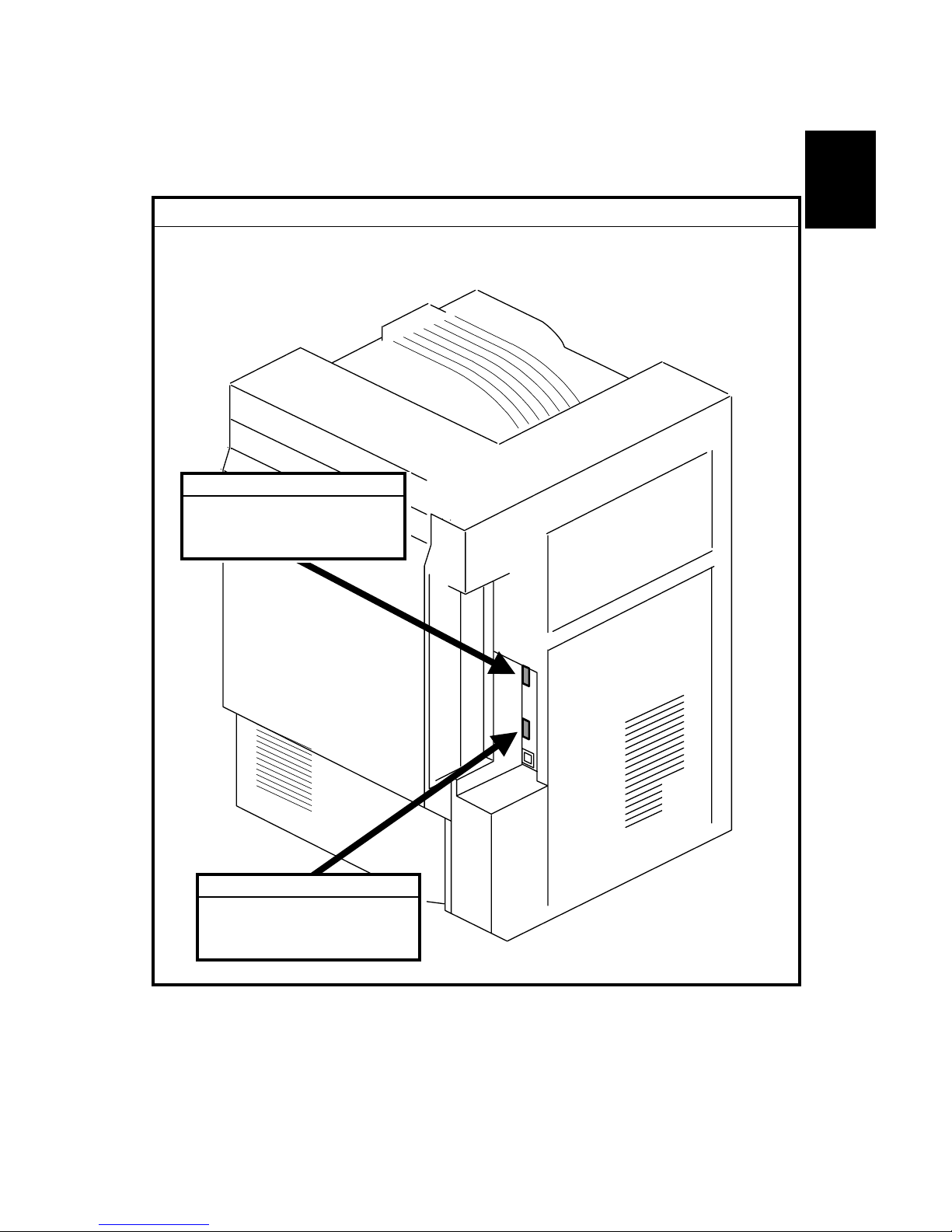
1.3.1 POWER SOCKETS FOR PERIPHERALS
!CAUTION
Rating voltage for peripherals.
Make sure to plug the cables into the correct sockets.
G106I903.WMF
1. Duplex unit
Rating voltage output
connector for accessory
Max. DC24V
2. Finisher
Rating voltage output
connector for accessory
Max. DC24V
Page 18
PRINTER 20 February 2004
1-6
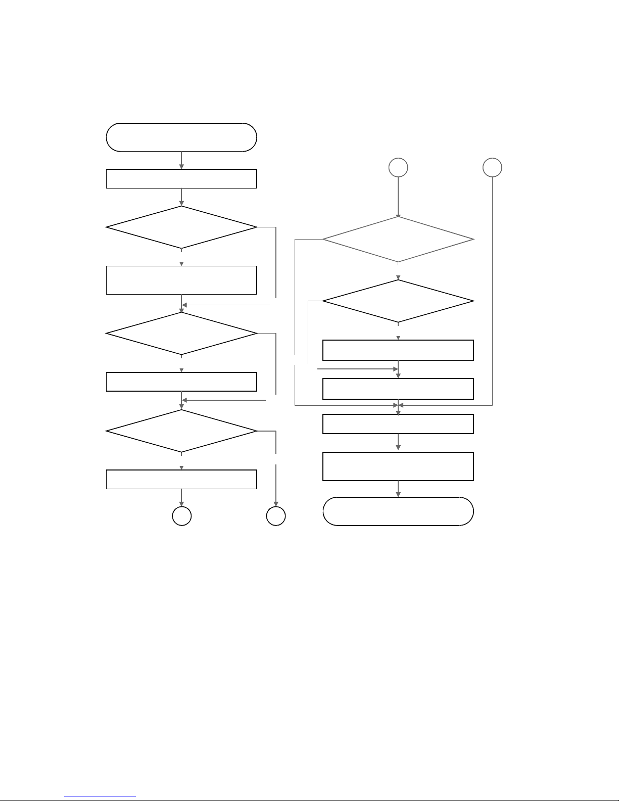
1.3.2 INSTALLATION FLOW CHART
The flow chart shows the installation procedure.
The two-tray finisher and the booklet finisher require ➀ the duplex unit and ➁ an optional paper
tray unit or the LCT. Each punch unit is dedicated to the two-tray finisher or the booklet finisher.
Start
The paper feed
unit or LCT to be installed?
Place the printer on the paper feed unit or
LCT, and install it.
Install the controller options.
Install the punch unit.
Install the printer.
Yes
Yes
No
No
Specify the settings relevant to the
contract (see section 1.3.3).
Unpack the printer.
End
A
A
No
Yes
Yes
Install the finisher.
No
The controller options to be
installed?
The two-tray finisher
or booklet finisher to be
installed?
The punch unit to be installed?
Install the duplex unit.
No
Yes
The duplex unit to be installed?
B
B
G106I904.WMF
Page 19

20 February 2004 PRINTER
1-7
Installation
1.3.3 INSTALLATION AND SETTINGS
For the installation procedure, see the Operating Instructions. After you install the
printer, make the settings that are necessary for the service contract. When you
make the settings, use caution:
1. Check the contract type carefully before you do steps 2 and 3. If you make the
wrong settings, you cannot change some settings back again.
2. You must enable Meter Charge (SP5-930-001) for any meter click counter
contract. The default is “OFF” (disabled).
3. If you set Meter Charge to “ON”, you must set Counter Methods (SP5-045)
(developments/prints) in accordance with the contract (☛ 5.3.1). If you change
the setting from “Prints” (default) to “Developments,” you cannot change the
setting back again.
The table shows the SP Mode settings related to service contracts.
Service Program Function
Meter Charge > ON/OFF
(SP5-930-001)
Enables or disables the Meter Charge. (Default: OFF
[Disabled])
When enabled:
• The Counter menu appears immediately after you push
the Menu key. The Counter Method (SP5-045) sets the
type of the counter.
• You can print the counter from the Counter menu.
• When the ACS mode is on, a monochrome page is
counted as such even if it follows a color page.
When disabled:
• The Counter menu is not displayed.
• The total counter starts from 0 (zero).
• When the ACS mode is on, a monochrome page is
counted as a color page if it follows a color page.
Meter Charge > Menu (SP5930-003)
Enables or disables the PM Alert for the PCUs, development
units, and fusing unit. (Default: Click 1 [Enabled])
When the PM Alert is enabled, a message is displayed
when one of the units needs to be replaced.
Meter Charge > Paper
Transfer (SP5-930-005)
Enables or disables the PM Alert for the transfer unit and
transfer cleaning unit. (Default: No Alert [Disabled])
Counter Method (SP5-045)
Tells the counter when to count (each development or each
print). (Default: 1 [Prints])
Double Count (SP5-104)
Specifies whether the counter increase by +1 or by +2 when
the paper size is A3 or 11" x 17". (Default: OFF [by +1])
Telephone Number Setting >
Service (SP5-812-001)
Shows or sets the telephone number of the service
representative.
Telephone Number Setting >
Fax Telephone Number
SP5-812-002
Shows or sets the fax number of the service station. The
number is printed on the counter list when the Meter Charge is
enabled. The user can send a fax message with the counter
list.
Page 20
PRINTER 20 February 2004
1-8
1.3.4 MOVING THE MACHINE
!CAUTION
Make sure that the transfer belt is in its correct position before moving the
printer, otherwise the transfer belt and the black PCU may be damaged.
NOTE: This section assumes that you manually move the machine to a different
floor in the same building. When using transportation equipment, see
section 1.3.5.
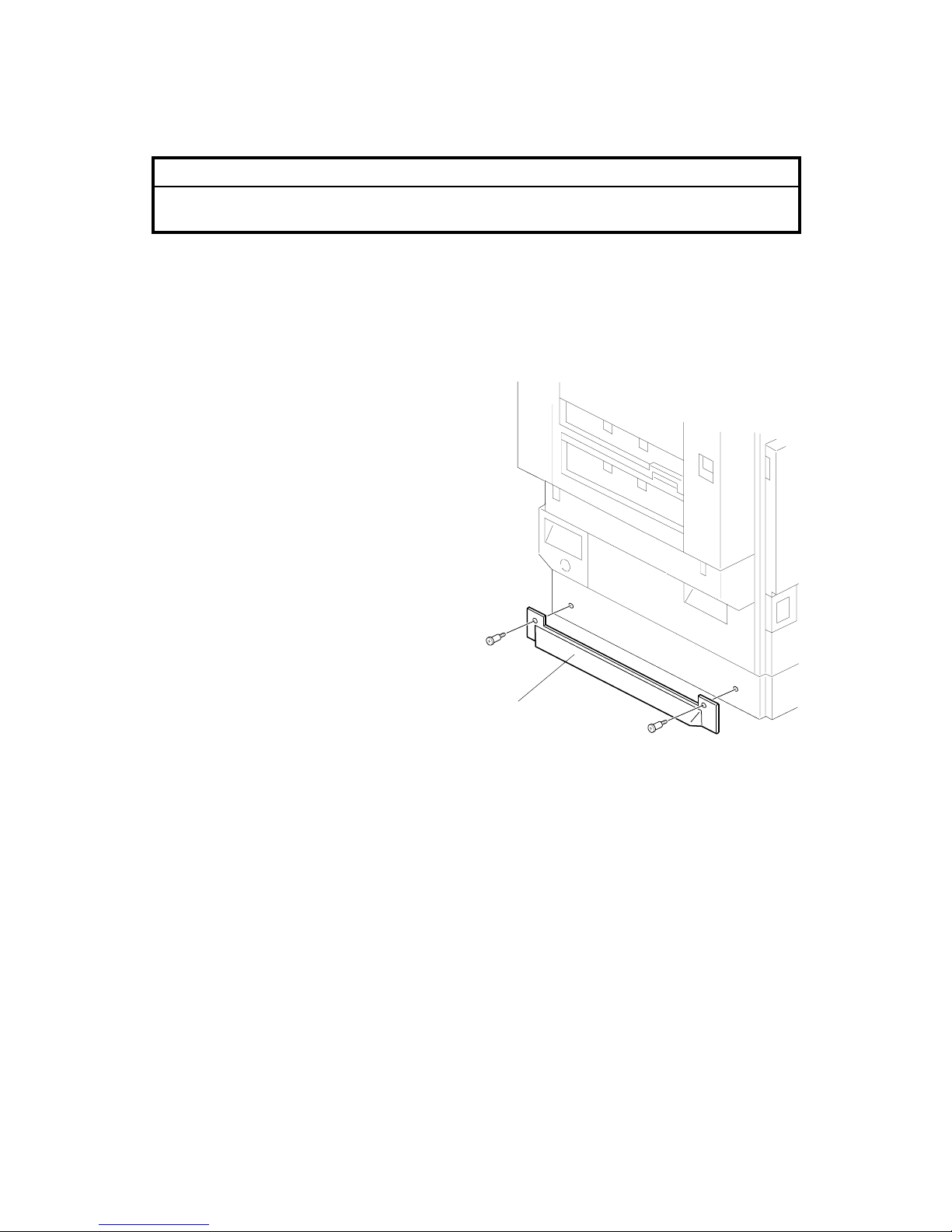
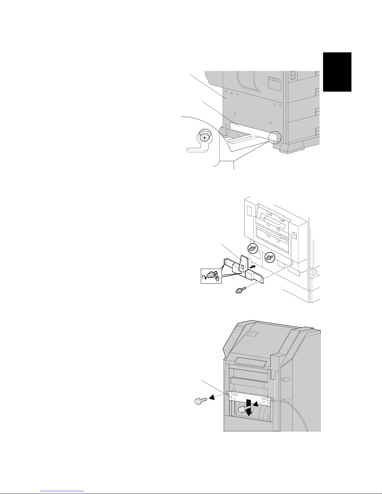
The supports on the paper feed unit or LCT make it difficult to move the machine.
You can remove them as necessary.
1. Check that the transfer belt is in the
correct position.
2. Remove the supports [A] from both
sides (! x 2 for each).
CAUTION: After moving the machine, reinstall the supports. Without them, the
machine may tip over when you draw out a paper tray or while you
work on the printer.
G106I905.WMF
[A]
Page 21

20 February 2004 PRINTER
1-9
Installation
1.3.5 TRANSPORTING THE MACHINE
Read this section when you use transportation equipment to move the machine.
When you manually move the machine to a different floor in the same building, see
section 1.3.4.
After a Machine Test
If you install the machine in your office to do a test before you send the machine to
the user, do these steps.
1. When you do your tests
• Do not use the oil supply unit that comes as an accessory with the machine.
2. When you send the machine after the tests:
• Remove the oil supply unit that you used for the tests.
If you keep the oil supply unit installed in the machine, the oil supply roller in the
fusing unit can move up and down during transportation. As a result, the oil
supply roller constantly supplies oil to all the fusing mechanism. This oil can
cause damage to the fusing mechanism, especially to the holder at the bottom of
the unit.
Transporting a Used Machine
When you move a used machine to a different location, you must discard the oil
supply unit (☛ After a Machine Test). After you install the machine at a new
location, install a new oil supply unit.
Necessary Adjustment after Transportation
After you install the machine at a new location, do the Line Adjustment (SP5-993-
002) or the Auto Adjustment (Menu > Maintenance > Color Regist. > Auto Adjust).
When you do one of these programs, make sure that the tray fences are set
correctly. If not set correctly, tray fences can make color images shift.
Page 22
PRINTER 20 February 2004
1-10
Preparing the Printer
!CAUTION
Make sure that the transfer belt is in its correct position before moving the
printer, otherwise the transfer belt and the black PCU may be damaged.
1. Check that the transfer belt is in its correct position.
2. Remove the supports (☛ 1.3.4).
3. Remove the toner bottles to prevent toner from flowing into the toner supply
tubes during transport. This may cause the tube to be clogged with toner.
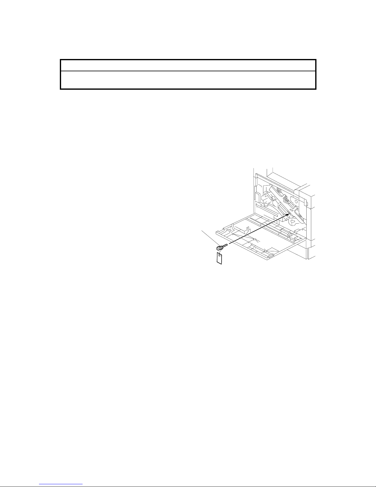
4. Put air packing into the toner cartridge holders to shield the toner supply
entrances. This prevents toner from flowing out to the toner cartridge holders.
5. Set the lock pin [A] (which comes
with the machine) in the transfer
belt unit.
NOTE: The lower end of the
transfer belt moves. The
surfaces of the belt and
PCU may be damaged by
the friction between them if
you transport the machine
without locking the belt.
6. Make sure there is no paper left in the paper trays and fix down the bottom
plates with a sheet of paper and tape.
7. Empty out the waste toner bottle and attach securing tape to prevent the bottle
from coming out.
8. Empty out the waste oil bottle and attach securing tape to prevent the bottle
from coming out.
G106I906.WMF
[A]
Page 23

20 February 2004 PRINTER
1-11
Installation
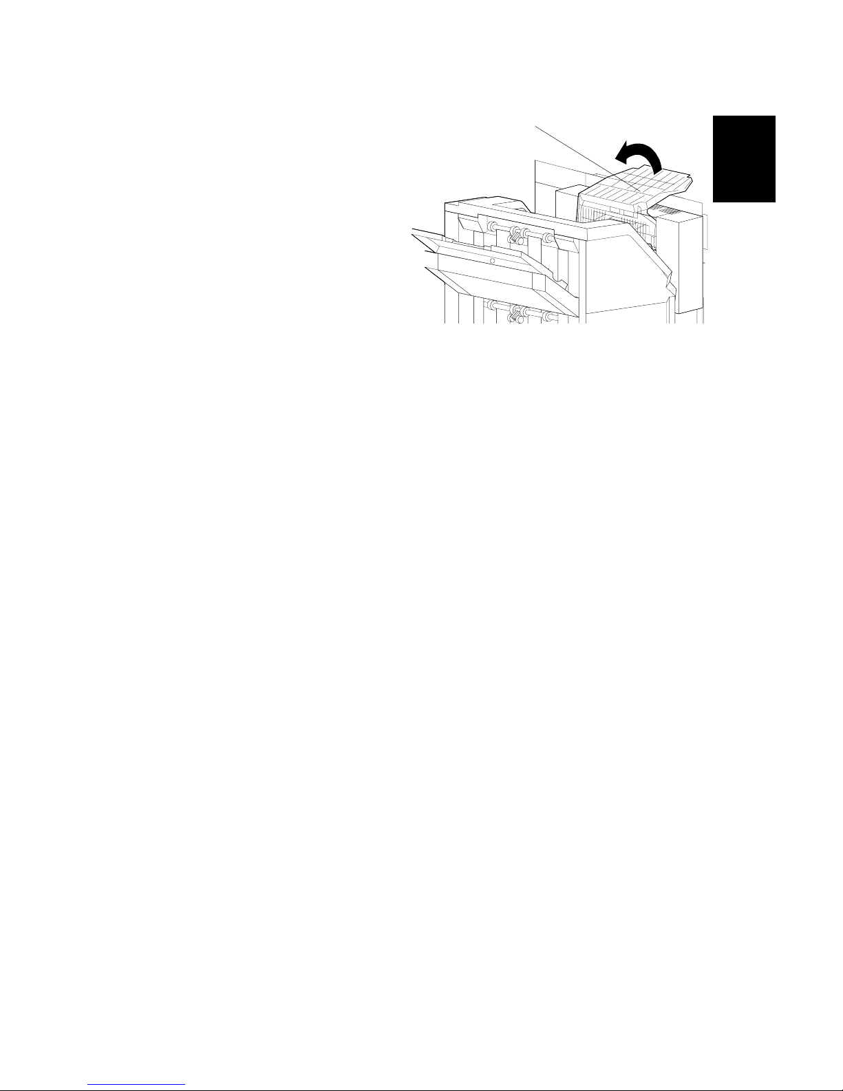
9. Turn the release lever [A]
counterclockwise to its lowermost
position. (The lever does not stay in
this position if you do not hold it.)
Stick the lever in this position with
tape.
NOTE: The release lever lifts the
transfer belt up and presses
it against the black PCU.
The surfaces of the belt and
PCU may be damaged by
the friction between them if
you transport the machine
with the two units in this
position.
10. Attach shipping tape to the covers and doors, or shrink-wrap the machine
tightly.
G106I907.WMF
[A]
Page 24
OPTIONAL UNIT 20 February 2004
1-12
1.4 OPTIONAL UNIT
1.4.1 TWO-TRAY FINISHER
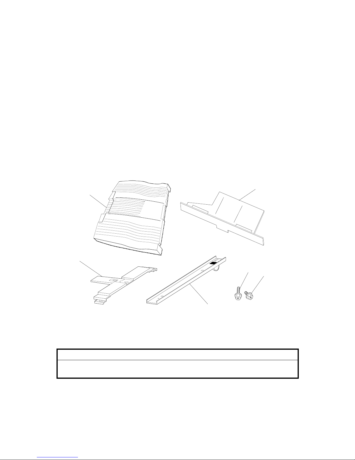
Accessory Check
Check the quantity and condition of the accessories.
Description Q’ty
1. Tray.............................................................................................2
2. Link-rail holder.............................................................................1
3. Screw M4 x 8 ..............................................................................2
4. Screw M4 x 12.............................................................................6
5. Link rail........................................................................................1
6. Duplex-unit support .....................................................................1
Installation Procedure
!CAUTION
Turn off the main switch of the printer and unplug its power cord before
starting the installation procedure.
G106I908.WMF
1
2
3
4
5
6
Page 25
20 February 2004 OPTIONAL UNIT
1-13
Installation
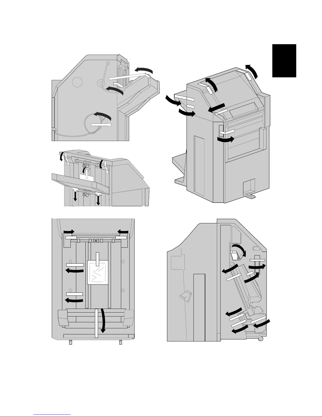
1. Remove all tape and packing materials.
G106I912.WMF
G106I909.WMF
G106I910.WMF
G106I911.WMF
G106I913.WMF
Page 26
OPTIONAL UNIT 20 February 2004
1-14
2. Fold the external tray [A].
3. Remove the support on the left side
[B] (! x 2).
4. Set the link rail [C] on the link-rail
holder [D].
G106I914.WMF
G106I916.WMF
G106I917.WMF
[A]
[C]
[D]
[B]
Page 27
20 February 2004 OPTIONAL UNIT
1-15
Installation
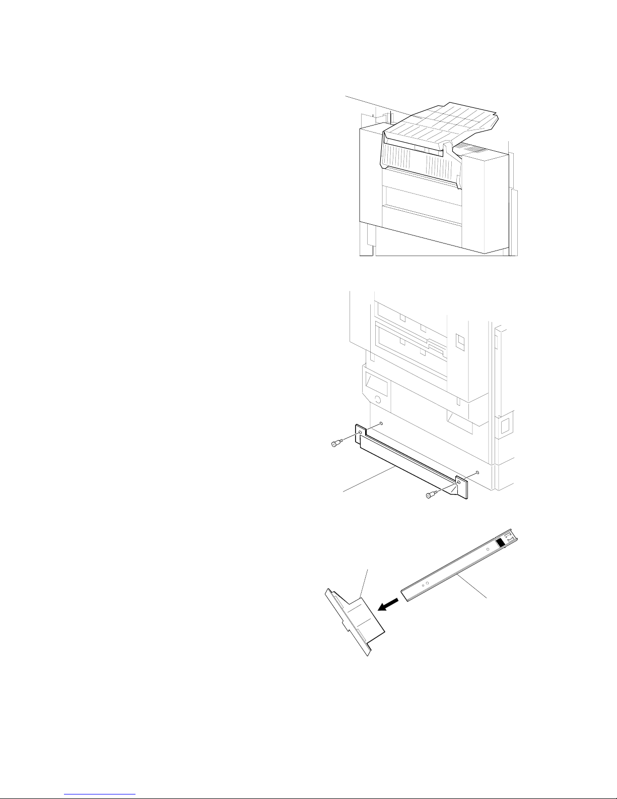
5. Install the link-rail holder (with
the link rail) [A] on the printer
[B] (! x 2).
6. Install the duplex-unit support [C] on
the duplex unit (! x 3).
7. Adjust the position of the connection
bracket [D] as necessary (! x 2):
• Upper position for the printer with
the two-tray paper feed unit or
LCT.
• Lower position for the printer with
the one-tray paper feed unit.
G106I918.WMF
G106I919.WMF
G106I920.WMF
[C]
[A]
[B]
[D]
Page 28
OPTIONAL UNIT 20 February 2004
1-16
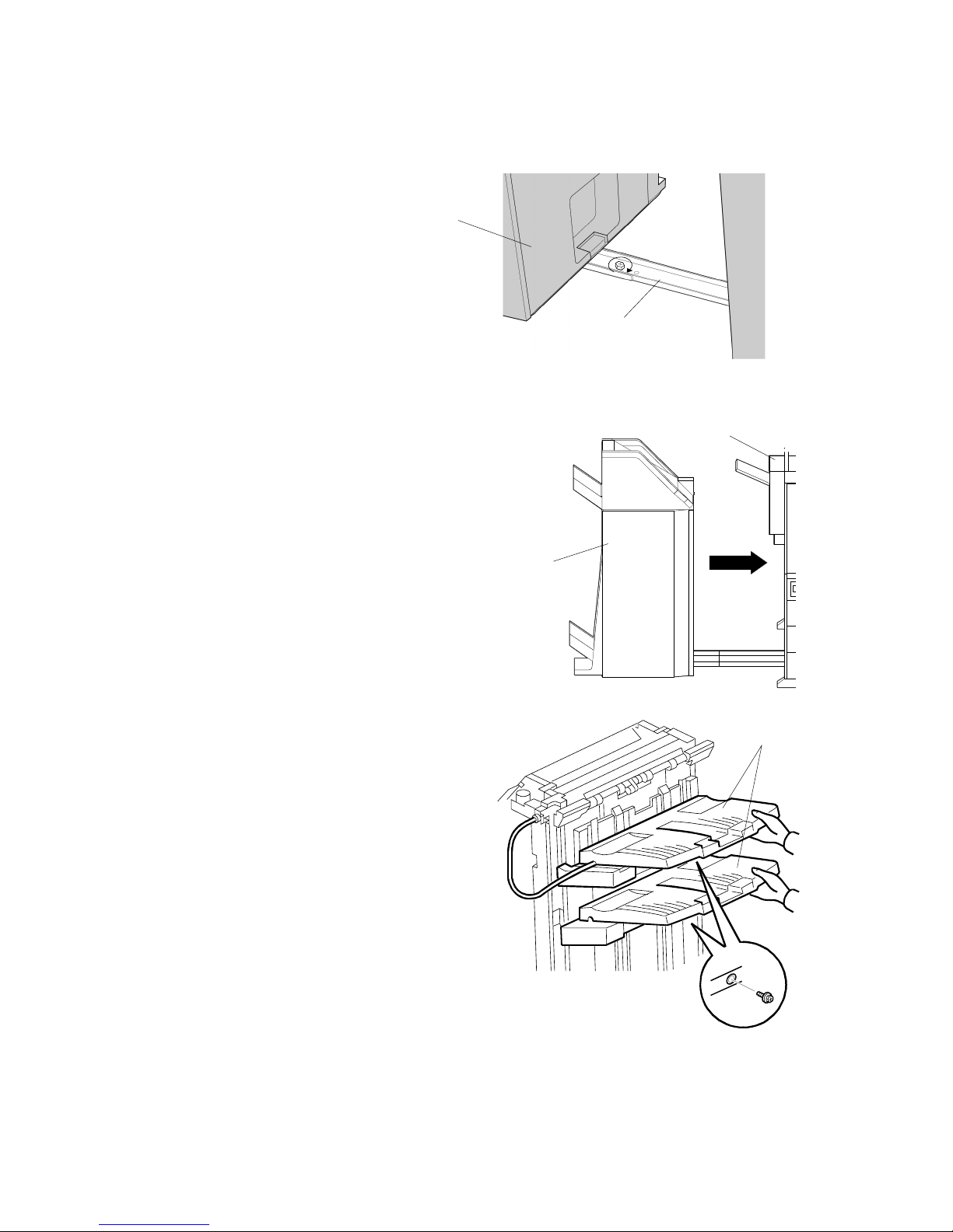
8. Attach the rail [A] to the finisher [B]
(! x 1).
9. Connect the finisher [C] with the printer [D].
10. Connect the finisher cable to the connector of
the printer.
11. Install the two trays [E]
(! x 1 for each).
G106I921.WMF
G106I922.WMF
G106I923.WMF
[A]
[B]
[C]
[D]
[E]
Page 29
20 February 2004 OPTIONAL UNIT
1-17
Installation
12. Extend the external tray [A] of the
printer.
13. Turn on the main power switch
and check the operation.
G106I924.WMF
[A]
Page 30
OPTIONAL UNIT 20 February 2004
1-18
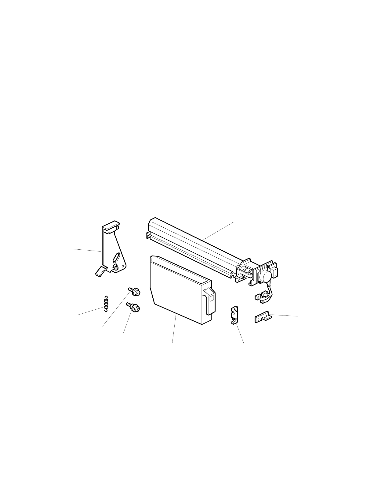
1.4.2 PUNCH UNIT
Accessory Check
Check the quantity and condition of the accessories.
Description Q’ty
1. Punch unit........................................................................... 1
2. Sensor arm ......................................................................... 1
3. Spring.................................................................................. 1
4. Screw M3 x 6 ...................................................................... 2
5. Step screw .......................................................................... 2
6. Hopper ................................................................................ 1
7. Spacer (2 mm) .................................................................... 1
8. Spacer (1 mm) .................................................................... 2
G106I925.WMF
1
2
3
4
5
6
7
8
Page 31

20 February 2004 OPTIONAL UNIT
1-19
Installation
Installation Procedure
!CAUTION
Switch off the main machine and unplug its power cord. If the two-tray
finisher has been installed, disconnect it and pull it away from the machine.
1. Unpack the punch unit and remove all tapes and shipping retainers.
2. Open the front door and remove the rear cover [A] (! x 4).
3. Remove the bracket [B] (! x 2) and paper guide [C] (stepped ! x 1).
G106I926.WMF
G106I927.WMF
[A]
[B]
[C]
Page 32

OPTIONAL UNIT 20 February 2004
1-20
4. Remove the hopper cover [A] (! x 2).
5. Install the sensor bracket [B] (stepped ! x 1).
6. Install the spring [C].
7. Install the 2 mm spacer [D].
8. Install the punch unit [E] (! x 2, stepped ! x 1).
G106I928.WMF
G106I929.WMF
[A]
[B]
[C]
[D]
[E]
Page 33

20 February 2004 OPTIONAL UNIT
1-21
Installation
9. Connect the harnesses [A] and clamp them as shown.
10. Slide in the hopper [B].
11. Fasten the two 1-mm spacers [C] to the rear frame for future adjustment.
NOTE: The spacers are used to adjust the horizontal positioning of the punch
holes.
12. Reassemble the finisher and check the punch operation.
G106I930.WMF
G106I931.WMF
[B]
[A]
[C]
Page 34

OPTIONAL UNIT 20 February 2004
1-22
1.4.3 BOOKLET FINISHER
Accessory Check
Check the quantity and condition of the accessories.
Description Q’ty
1. Regular tray.................................................................................1
2. Rail holder................................................................................... 1
3. Magnet catch–rear ......................................................................1
4. Magnet catch–front......................................................................1
5. Duplex-unit support .....................................................................1
6. Rail joint ......................................................................................1
7. Screw M4 x 12.............................................................................6
8. Screw M4 x 6 ..............................................................................8
9. Screw M3 x 14.............................................................................4
10. Rail............................................................................................1
11. Stapler unit................................................................................ 1
12. Staple cartridge .........................................................................1
13. Pad............................................................................................3
NOTE: Make sure that you retain the pads. The pads are white and made of
Styrofoam.
G106I932.WMF
10
11
12
13
1
2
3
4
5
6
7
8
9
Page 35

20 February 2004 OPTIONAL UNIT
1-23
Installation
Adjusting the Height
1. Check the type of the optional paper tray:
• If the optional two-tray paper feed unit or the optional LCT is installed, go to
step 2.
• If either of them is not installed, go to “Main Body.”
2. Tape the pads [A] to the right-hand side of the machine.
3. Lay the machine on its right-hand side.
4. Remove the adjuster plates [B] (! x 2).
5. Change the height [C].
6. Reinstall the adjuster plates [D].
7. Take out the machine from the box and stand it up.
8. Check that the height is correct, and remove the pads.
G106I934.WMF
G106I933.WMF
[B]
[C]
[D]
[A]
Page 36

OPTIONAL UNIT 20 February 2004
1-24
Main Body
1. Remove all tape and padding.
2. Remove the screw cover [A].
3. Install the rail joint [B] (! x 4).
4. Reinstall the screw cover.
5. Install the regular tray [C] (! x 4).
G106I935.WMF
G106I936.WMF
G106I937.WMF
[C]
[B]
[A]
Page 37

20 February 2004 OPTIONAL UNIT
1-25
Installation
6. Install the magnet catches [A][B]
(! x 2 for each).
7. Install the duplex-unit support [C] (! x 3).
8. Remove the support on the left side [D] (!
x 2).
9. Set the rail [E] through the rail holder [F].
10. Install the rail holder (with the rail) to the
printer (! x 2).
G106I938.WMF
G106I939.WMF
G106I940.WMF
[A]
[B]
[C]
[E] [F]
[D]
Page 38

OPTIONAL UNIT 20 February 2004
1-26
11. Connect the booklet finisher unit to
the printer (! x 1).
12. Install the stapler unit [A].
13. Turn the knob [B] clockwise until the
staple-cartridge holder [C] reaches the
front-most position.
14. Install the staple cartridge [D] firmly to
the staple-cartridge holder.
15. Turn on the main switch and check the operation.
G106I941.WMF
G106I942.WMF
G106I943.WMF
[A]
[D]
[B]
[C]
Page 39

20 February 2004 OPTIONAL UNIT
1-27
Installation
1.4.4 OPTIONAL PUNCH UNIT
Accessory Check
Check the quantity and condition of the accessories.
Description Q’ty
1. Punch unit........................................................................... 1
2. Decal................................................................................... 1
3. Screw M4 x 6 (with the base).............................................. 1
4. Cable................................................................................... 2
Installation Procedure
1. Remove the front lower cover
[A] (! x 2).
G106I944.WMF
G106I945.WMF
1
2
3
4
[A]
Page 40

OPTIONAL UNIT 20 February 2004
1-28
2. Remove the joint guard [A] (! x 2).
3. Open the front door [B].
4. Release the stopper and remove the knob [C].
5. Remove the front cover [D] (! x 4).
6. Remove the rear cover [E] (! x 3).
NOTE: Do not damage the Mylar when you remove the screw.
7. Remove the right top cover with the paper entrance cover [G] (! x 4).
G106I946.WMF
[A]
[D]
[E]
[G]
[C]
[B]
Page 41

20 February 2004 OPTIONAL UNIT
1-29
Installation
8. Remove the right top cover [A] from
the paper entrance cover [B].
9. Install the punch unit [C] (! x 2,
1 screw with the base [D])
10. Install the right top cover [E] (! x 2).
G106I947.WMF
G106I948.WMF
G106I949.WMF
[A]
[B]
[E]
[C]
[D]
Page 42

OPTIONAL UNIT 20 February 2004
1-30
11. Install the cable to the connectors as follows:
• J1003 (punch unit) [A] to CN12 (booklet finisher unit) [D]
• J1004 (punch unit) [B] to CN14 (booklet finisher unit) [C]
12. Fasten the cable with the clamps.
13. Reassemble the booklet finisher unit.
NOTE: Check that the side guide and the front cover correctly join with each
other [E].
14. Attach the decal [F].
15. Turn on the main switch and check the punch operation.
G106I950.WMF
G106I951.WMF
G106I952.WMF
[A]
[B]
[D]
[C]
[E]
[F]
Page 43

20 February 2004 USER MAINTENANCE
2-1
Preventive
Maintenance
2. PREVENTIVE MAINTENANCE
2.1 USER MAINTENANCE
Maintenance Kit
The table shows the maintenance kits for the user.
Kit Component Expected Yield (Prints)
A Color PCU (3 PCUs for CMY) 50k
B Color Development Unit (3 units for CMY) 100k
C Fusing Unit (without Oil Supply Unit) 100k
D Black Development Unit and Dust Filter 100k
E Waste Toner Bottle 50k
F Black PCU 50k
G Oil Supply Unit 30k
NOTE: The yield is calculated for these conditions: A4 (LT) LEF, 5% image
coverage ratio, 5 prints per job.
PM Alert Display
Model J-P3 can show a PM Alert (an error message) when a unit or component
must be replaced. The table shows the SPs related to PM Alerts.
Service Program Function
Meter Charge > Menu (SP5-930-003) Enables or disables the PM Alert for the PCUs,
development units, and fusing unit.
Alert Display > Waste Oil: Full (SP7-905-
010)
Sets the number of revolutions the development
drive motor-K can make after “Waste Oil Bottle is
Almost Full”, is shown.
Alert Display > Oil: Alert: Page (SP7-905-
014)
Sets the number of sheets the printer can output
after the fusing oil gets to the near end condition.
Model J-P3 stops operation if the user does not replace the waste toner bottle or
the oil supply unit when the machine tells the user to do this.
New Unit Detection
When the user replaces a unit or component that is a part of a maintenance kit,
Model J-P3 automatically detects the unit or component. The related counter(s)
(one or some of SP7-803-001 to 049) will be set to zero.
Page 44

USER MAINTENANCE 20 February 2004
2-2
PM Table
Symbol key: C: Clean, R: Replace, L: Lubricate, I: Inspect
Main Unit
Item 30K 50K 100K 150K EM Remarks
Black PCU R
Color (Y/M/C) PCU R
Black Development Unit R
Color (C/M/Y) Development Unit R
Fusing Unit R
Oil Supply Unit R
Waste Toner Bottle R
Dust Filter R
Circuit Breaker I At least once a month
Punch Kit
Item 10K EM Remarks
Chads I Discard chads.
Page 45

20 February 2004 SERVICE MAINTENANCE
2-3
Preventive
Maintenance
2.2 SERVICE MAINTENANCE
PM Counter Reset
Reset the related PM Counter after you replace a unit or component that is not a
part of a maintenance kit (☛ 2.1). To do this, use PM Counter Reset (SP7-804).
The table shows the service programs that you must use.
SP7-804-011 By-pass Tray Feed Roller SP7-804-015 Paper Feed Tray 4 Feed Roller
SP7-804-012 Paper Feed Tray 1 Feed Roller SP7-804-017 Transfer Unit
SP7-804-013 Paper Feed Tray 2 Feed Roller SP7-804-018 Transfer Cleaning Unit
SP7-804-014 Paper Feed Tray 3 Feed Roller
PM Table
Symbol key: C: Clean, R: Replace, L: Lubricate, I: Inspect
Main unit
Item 100K 150K 500K 1,000K 3,000K EM Remarks
Transfer Unit R
Transfer Cleaning Unit R
By-pass Feed Roller R
By-pass Pick-up Roller R
By-pass Separation Roller R
Waste Oil Bottle R
Pick-up Roller R
Feed Roller R
Separation Roller R
One-tray Paper Feed Unit (500 sheets x 1)
Item 100K 150K 500K 1,000K 3,000K EM Remarks
Relay Roller C Damp cloth
Bottom Plate Pad C Damp cloth
Pick-up Roller R
Feed Roller R
Separation Roller R
Two-tray Paper Feed Unit (500 sheets x 2)
Item 100K 150K 500K 1,000K 3,000K EM Remarks
Relay Roller C Damp cloth
Bottom Plate Pad C Damp cloth
Pick-up Roller R
Feed Roller R
Separation Roller R
Page 46

SERVICE MAINTENANCE 20 February 2004
2-4
LCT (2000 sheets)
Item 100K 150K 500K 1,000K 3,000K EM Remarks
Relay Roller C Damp cloth
Bottom Plate Pad C Damp cloth
Pick-up Roller R
Feed Roller R
Separation Roller R
Two-tray Finisher
Items 100K 150K 500K 1,000K 3,000K EM Remarks
Rollers C Damp cloth
Discharge Brush C Dry cloth
Sensors C Blower brush
Jogger Fences I Replace if required.
Page 47

20 February 2004 MODEL J-P3 AND MODEL J-P2
3-1
Replacement
Adjustment
3. REPLACEMENT AND ADJUSTMENT
!CAUTION
Turn off the main power switch and unplug the printer before removing any
part of the printer.
3.1 MODEL J-P3 AND MODEL J-P2
While reading this chapter, keep Model J-P2 Service Manual at hand. This chapter
frequently refers to Model J-P2.
Model J-P3 and Model J-P2 have common features and components. Model J-P2
Service Manual gives you the information on these features and components. This
chapter illustrates the features and components that are supported only by Model
J-P3.
Symbols in this chapter:
☛: See Model J-P3 Service Manual
☛ [P2]: See Model J-P2 Service Manual
!: Screw
": Connector
#: Clip ring
$: E ring
3.2 SPECIAL TOOLS
Part Number Part Name Q’ty
B6455010 SD Card 1
B6456700 PCMCIA Card Adapter 1
B6456800 USB Reader/Writer 1
A029 9387 Digital Multimeter–FLUKE87 1
G021 9350 Loop-back Connector–Parallel 1
C401 9503 20X Magnification Scope 1
A2579300 Grease Barrierta–S552R 1
52039501 Silicon Grease G-501 1
Page 48

LASER OPTICS 20 February 2004
3-2
3.3 LASER OPTICS
!
WARNING
Turn off the main power switch and unplug the printer before beginning
any of the procedures in this section. Laser beams can cause serious eye
injury.
3.3.1 CAUTION DECAL LOCATIONS
Caution decals are attached as shown below.
! WARNING
Be sure to turn off the main power switch and disconnect the power plug
from the power outlet before beginning any disassembly or adjustment of
the laser unit. This printer uses a class IIIb laser beam with a wavelength
of 655 nm and an output of 7 mW. The laser can cause serious eye injury.
G106R927.WMF
G106R901.WMF
G106R928.WMF
Page 49

20 February 2004 LASER OPTICS
3-3
Replacement
Adjustment
3.3.2 LASER OPTICS HOUSING UNIT
CAUTION: 1) Before installing a new laser optics housing unit, remove the sponge
padding and the tag from the new unit.
2) Do not remove the polygon mirror from its base. If you do this, the
lubricant on the shaft can leak out after you reassemble the printer.
Steps 1 through 4 refer to the
procedure for a newly supplied unit
that replaces the old one.
1. Top cover of the laser optics
housing unit [A] (! x 4)
2. Sponge padding [B]
3. Tag [C]
4. Reinstall the top cover.
5. Rear cover, upper rear cover
(☛ [P2] 3.3.1)
6. Paper exit tray (☛ [P2] 3.3.2)
7. Right cover, upper right cover
(☛ [P2] 3.3.3)
8. Operation panel
(☛ [P2] 3.3.6)
9. Black PCU cooling fan [D]
(" x 1, ! x 1)
G106R905.WMF
G106R924.WMF
[B]
[C]
[A]
[D]
Page 50

LASER OPTICS 20 February 2004
3-4
10. Securing screws for the toner
supply unit [A] (! x 4)
11. Securing screws for the laser
optics housing unit [B] (! x 2)
12. Lift the toner supply unit [C]
➀,
and
lower it ➁.
NOTE: The pins on the front side
[D] and the rear side hold
the toner supply unit.
G106R903.WMF
G106R908.WMF
[C]
[D]
[A]
[A]
[B]
Page 51

20 February 2004 LASER OPTICS
3-5
Replacement
Adjustment
13. Connector cover [A] (! x 1)
14. Four flat cables [B]
15. Connector [C]
16. Flat cable bracket [D] (! x 1)
17. Release the cable from the clamps
[E].
G106R904.WMF
G106R936.WMF
[E]
[D]
[A]
[B]
[C]
Page 52

LASER OPTICS 20 February 2004
3-6
18. Duct [A]
19. Securing screws for the laser optics housing unit [B] (! x 2)
NOTE: When reassembling, attach the ground cable [C].
20. Put a sheet of paper [D] between the laser optic housing unit and the machine
rear frame.
NOTE: This ensures that the cables are not caught by the brackets when you
lift the laser optics housing unit.
21. Hold the unit with both hands and lift it up slowly, making sure that the flat
cables from the laser diode board are not caught by the brackets.
NOTE: If you roughly remove the unit, the cables can be caught by the
brackets and the laser diode board may be damaged.
22. Do SP5-993-002 (Line Adjustment > Execute) or Auto Adjustment in the User
Tools (Maintenance > Color Regist. > Auto Adjust. > Now).
G106R906.WMF
[A]
[D]
[C]
[B]
Page 53

20 February 2004 LASER OPTICS
3-7
Replacement
Adjustment
3.3.3 POLYGON MIRROR MOTOR
1. Laser optics housing unit
(☛ 3.3.2)
2. Top cover [A] (! x 4)
3. Flat cable on the polygonmirror-motor drive-board [B]
4. Eight connectors [C] on the
four LD boards
5. Upper cover [D] (" x 9, ! x 6)
NOTE: Two of the nine
connectors are on the
opposite side of the
upper cover.
6. Air-current rectifier [E] (! x 3)
7. Polygon mirror motor [F] (! x 4)
G106R921.WMF
G106R922.WMF
G106R923.WMF
[A]
[B]
[C]
[D]
[F]
[E]
Page 54

LASER OPTICS 20 February 2004
3-8
3.3.4 POLYGON MIRROR MOTOR DRIVE BOARD
1. Laser optics housing unit
(☛ 3.3.2)
2. Polygon mirror motor drive
board [A] (! x 2, " x 1,
1 flat cable)
3.3.5 LASER SYNCHRONIZING DETECTOR BOARDS
1. Laser optics housing unit
(☛ 3.3.2)
2. Synchronizing detector boards
[A] (! x 1, " x 1)
G106R907.WMF
G106R937.WMF
[A]
[A]
Page 55

20 February 2004 PAPER FEED
3-9
Replacement
Adjustment
3.4 PAPER FEED
3.4.1 REGISTRATION SENSOR AND RELAY SENSORS
1. Right door unit (☛ [P2] 3.6.4)
2. Lift the registration guide [A]
(! x 2)
NOTE: It is not necessary to
fully lift the registration
guide. You can get
access to the screw of
the registration sensor
bracket when you lift the
guide half the distance.
3. Registration sensor bracket [B]
(! x 2)
4. Registration sensor [C]
(! x 1, " x 1)
NOTE: When you reassemble,
make sure that the
connector does not
come off.
5. Relay sensor bracket [D] (! x 1)
NOTE: Remove the registration
sensor bracket first. You
have easier access to
the relay sensor bracket.
6. Relay sensor [E] (" x 1)
G106R909.WMF
G106R938.WMF
[A]
[B]
[C]
[D]
[E]
Page 56

PAPER FEED 20 February 2004
3-10
3.4.2 BY-PASS FEED CLUTCH
1. Right door unit
(☛ [P2] 3.6.4)
2. By-pass tray cover [A]
(! x 1, 1 hook)
3. Upper guide plate [B]
(! x 4)
NOTE: It is not necessary
to remove the
connectors on the
bottom side of the
upper guide plate.
4. Support plate [C] ($ x 2)
5. Relay gear [D]
6. By-pass feed clutch [E] (" x 1)
3.4.3 PAPER FEED MOTOR
1. Rear cover (☛ [P2] 3.3.1)
2. Swing out the high voltage
supply unit. (☛ [P2] 3.10.2)
3. Sub power supply unit
(☛ 3.8.3)
NOTE: The cable of the paper
feed motor goes
behind the sub power
supply unit.
4. Paper feed motor [A] (! x 3,
" x 1)
NOTE: The connector is
CN604 on the driver
board [B].
G106R910.WMF
G106R939.WMF
[A]
[B]
[D]
[C]
[E]
[A]
[B]
Page 57

20 February 2004 TRANSFER AND PAPER TRANSPORT UNIT
3-11
Replacement
Adjustment
3.5 TRANSFER AND PAPER TRANSPORT UNIT
3.5.1 TRANSFER UNIT
NOTE: When removing or installing the transfer unit, grasp the grip on the front
frame and the center of the rear frame. Do not touch the transfer belt [A].
Do not damage the entrance Mylar [B].
1. Turn the release lever counterclockwise (☛ [P2] 3.5).
2. Pull out the transfer unit [C] until the entire unit is visible (! x 2).
3. Grasp the handle on the front frame and the center of the rear frame, and lift
the unit to remove it.
After replacing the transfer unit:
• Reset the maintenance counter, SP7-804-017
• Remove all the PCUs.
• Do the transfer belt idling with SP5-804-066 for 1 minute.
• Install the PCUs.
• Perform forced line position adjustment (SP5-993-002 or Menu > Maintenance >
Color Regist. > Auto Adjust).
• Print the 1-dot grid pattern on A3/11" x 17" paper and check the color shift level
(☛ [P2] 4.4.3).
G106R940.WMF
[A]
[C]
[B]
Page 58

TRANSFER AND PAPER TRANSPORT UNIT 20 February 2004
3-12
3.5.2 TRANSFER BELT CLEANING UNIT
CAUTION: Push the lever [A] and hold it there while you remove or install the
transfer belt cleaning unit. The blade [B] can cause damage to the
transfer belt if you do not continue to push the lever.
While pushing the lever [A], pull out
the transfer belt cleaning unit (! x 1).
Adjustment and Setting
After replacing the transfer belt
cleaning unit, reset the maintenance
counter (SP7-804-018).
After replacing the transfer belt
cleaning unit, do the forced line
position adjustment (SP5-993-002 or
Menu > Maintenance > Color Regist.
> Auto Adjust).
3.5.3 CLEANING BLADE AND CLEANING ROLLER
1. Transfer belt cleaning unit
(☛ 3.5.2)
2. Cleaning blade [A] (! x 2)
G106R941.WMF
G106R950.WMF
[A]
[A]
[B]
Page 59

20 February 2004 TRANSFER AND PAPER TRANSPORT UNIT
3-13
Replacement
Adjustment
3. 3 gears [A] ($ x 1)
4. Lever [B]
5. Gear box [C] (! x 1)
6. Cleaning brush gear [D]
($ x 1)
7. Bushing [E]
8. Cleaning brush [F]
Setting
After replacing the cleaning blade, do the forced line position adjustment (SP5-993002 or Menu > Maintenance > Color Regist. > Auto Adjust).
G106R913.WMF
G106R912.WMF
[A]
[C]
[B]
[F]
[D]
[E]
Page 60

TRANSFER AND PAPER TRANSPORT UNIT 20 February 2004
3-14
3.5.4 TRANSFER UNIT DRIVE MOTOR
1. Pull out the transfer unit
(☛ 3.5.1).
2. Transfer belt cleaning unit
(☛ 3.5.2)
3. Release lever [A] (! x 1)
4. Front cover [B] (! x 3)
5. Front plate [C] (! x 5, " x 1,
Timing belt x 1)
6. Transfer unit drive motor [D]
(! x 2, " x 1)
Reassembling
Before you attach the screw at the
left end [E], check that the timing
belt [F] is sufficiently tight. The
screw [E] adjusts the position of the
roller [G]. This roller pushes the
timing belt [H], to make sure that the
belt tightly engages with the drive
motor [I] and the drive gear [J].
G106R943.WMF
G106R944.WMF
G106R932.WMF
[A]
[B]
[C]
[D]
[E]
[G]
[H]
[I]
[J]
[F]
[E]
Page 61

20 February 2004 ID SENSORS
3-15
Replacement
Adjustment
3.6 ID SENSORS
1. Transfer unit (☛ 3.5.1).
2. Fusing unit (☛ [P2] 3.9.1)
3. Black PCU (☛ [P2] 3.5)
4. ID sensor bracket [A] (! x 2, " x 1)
Reassembling
Check that the ID sensor bracket receives the drum-positioning plate correctly.
G106R945.WMF
[A]
Page 62

FUSING 20 February 2004
3-16
3.7 FUSING
!
CAUTION
1. Make sure that the fusing unit is sufficiently cool before you touch it.
The fusing unit can be very hot.
2. Do not spill the silicone oil. Spilled silicone oil makes the floor slippery
and can cause serious accidents.
3. Do not tilt the fusing unit. The oil supply unit [A] can fall off the fusing
unit after the grip [B] is released from the oil supply unit.
3.7.1 CLEANING UNIT
1. Upper cover (☛ [P2] 3.9.2)
2. Spacer [A] (! x 1)
3. Front handle guide [B] (! x 1)
4. Rear handle guides [C] (! x 2)
5. Handle [D] (Spring x 1)
6. Cleaning unit [E] (! x 2)
G106R914.WMF
G106R946.WMF
[E]
[C]
[B]
[D]
[A]
Page 63

20 February 2004 FUSING
3-17
Replacement
Adjustment
3.7.2 PRESSURE ROLLER
1. Pressure roller fusing lamp (☛ [P2] 3.9.10)
2. Lower paper guide plate (☛ [P2] 3.9.8)
3. Drive gear holder [A] (! x 1)
4. Drive gear [B] ($ x 1)
5. Lower right cover (☛ [P2] 3.9.9)
6. Connector bracket [C] with the connector (! x 1)
7. Pads [D]
8. Release the fuse base [E] from the frame (! x 1).
NOTE: It is not necessary to remove the cables.
9. Thermistor (☛ [P2] 3.9.9)
NOTE: To prevent damage to the thermistor, remove the thermistor before you
remove the pressure roller unit.
10. Pressure roller unit [F] (! x 4)
NOTE: When you reassemble the machine, make sure that the pressure roller
unit does not cause damage to the cables.
G106R915.WMF
[A]
[B]
[F]
[D]
[C]
[E]
Page 64

FUSING 20 February 2004
3-18
11. Pressure roller gear [A] (C ring x 1)
12. Pressure roller holder [B] (! x 1)
13. Pressure roller [C] (C ring x 1, 2 bushings)
G106R916.WMF
[A]
[B]
[C]
Page 65

20 February 2004 FUSING
3-19
Replacement
Adjustment
3.7.3 FUSING UNIT FAN
!CAUTION
When reinstalling, make sure that the fan faces to the correct direction. The
arrow on the fan [D] and the arrow on the duct [D] must face to the same
direction.
1. Rear cover (☛ [P2] 3.3.1)
2. Left cover, rear left cover
(☛ [P2] 3.3.5)
3. Fusing fan duct [A]
(! x 2, " x 1)
4. Release the hooks and remove
the upper cover [B].
5. Fusing fan [C]
G106R917.WMF
G106R947.WMF
[A]
[B]
[C]
[D]
Page 66

ELECTRICAL COMPONENTS 20 February 2004
3-20
3.8 ELECTRICAL COMPONENTS
3.8.1 CONTROLLER AND BCU
NOTE: 1) Before replacing the BCU, the controller, or the NVRAM, print out the
SMC reports (“SP Mode Data” and “Logging Data”).
2) After replacing the BCU or the controller, remove the NVRAM from the
old board and install it on the new board. If the NVRAM on the old board
is defective, replace the NVRAM (☛ 3.8.2).
1. Controller [A] (! x 4)
2. Option bracket [B] (! x 4)
3. Rear cover [C] (☛ [P2] 3.3.1)
G106R918.WMF
[A]
[C]
[B]
Page 67

20 February 2004 ELECTRICAL COMPONENTS
3-21
Replacement
Adjustment
4. Connector cover [A] (! x 1)
5. Four flat cables [B]
6. Connector [C]
7. Cover bracket [D] (! x 5)
8. BCU [E] (All "'s, ! x 8)
CAUTION: 1) When handling NVRAMs, keep them away from any objects that can
cause static electricity. The data in NVRAMs may be corrupted by
static electricity.
2) Make sure the NVRAM is correctly installed on the board. A half-disk
[F] is engraved on one side of the NVRAM, while a guide mark [G] is
on one side of the NVRAM slot. Install the NVRAM so that the halfdisk and the guide mark are on the same side.
3) When replacing the BCU, make sure that the DIP-switch settings on
the old board and on the new board are the same (☛ 5.8).
G106R919.WMF
G106R920.WMF
[F]
[G]
[A]
[B]
[C]
[D]
[E]
Page 68

ELECTRICAL COMPONENTS 20 February 2004
3-22
3.8.2 NVRAM REPLACEMENT PROCEDURE
Make sure that you have the SMC report (factory settings) that comes with the
printer before beginning the following procedure.
NVRAM on the BCU
For this procedure, you must know the device number and the destination code (☛
step 10).
1. Start the SP mode.
2. Use SP5-990 to print out the SMC reports (“SP Mode Data” and “Logging
Data”) if possible.
3. Use SP5-824 to upload the NVRAM data if possible.
4. Turn off the main power switch and unplug the power cord.
5. Replace the NVRAM on the BCU and reassemble the machine.
6. Plug in the power cord.
7. Turn on the main power switch.
8. Start the SP mode.
9. Use SP5-825 to download the NVRAM data if possible.
10. Contact your supervisor to enter the machine’s device number.
NOTE: SC999 or “Fusing Unit Setting Error” may be displayed until the
machine’s device number and destination code are programmed
properly.
11. Turn the main power switch off and on.
12. If the NVRAM data is downloaded (☛ step 9), the following steps are not
required.
13. Start the SP mode.
14. Use SP5-998-1 to reset the engine settings.
15. Reset the meter charge settings (SP5-930-001 to 005).
16. Enter the SP mode changes previously made at the factory and the field.
17. Replace all maintenance kits with new ones.
Page 69

20 February 2004 ELECTRICAL COMPONENTS
3-23
Replacement
Adjustment
NVRAM on the Controller
1. Start the SP mode.
2. Use SP5-990 to print out the SMC reports (“SP Mode Data” and “Logging
Data”) if possible.
3. Use SP5-824 to upload the NVRAM data if possible.
4. Turn off the main power switch and unplug the power cord.
5. Replace the NVRAM on the controller and reassemble the machine.
6. Plug in the power cord.
7. Turn on the main power switch.
8. Start the SP mode.
9. Use SP5-825 to download the NVRAM data if possible. If it can be done, the
following steps are not required.
10. Use Memory Clear (SP5-801) to reset this data:
• SCS (SP5-801-003)
• PRT (SP5-801-008)
• NCS (SP5-801-011)
11. Do Counter Clear (SP7-808).
12. Make these contract-related settings:
• Counter Method (SP5-045)
• Double Count (SP5-104)
• Telephone Number Setting > Fax Telephone Number (SP5-812-002) if the
meter charge mode (SP5-930-001) is “ON” (enabled)
13. Enter the SP mode changes previously made at the factory and the field.
Page 70

ELECTRICAL COMPONENTS 20 February 2004
3-24
NVRAMs on the BCU and Controller
For this procedure, you must know the device number and the destination code (☛
step 10).
1. Start the SP mode.
2. Use SP5-990 to print out the SMC reports (“SP Mode Data” and “Logging
Data”) if possible.
3. Use SP5-824 to upload the NVRAM data if possible.
4. Turn off the main power switch and unplug the power cord.
5. Replace the NVRAMs on the BCU and the controller, and reassemble the
machine.
6. Plug in the power cord.
7. Turn on the main power switch.
8. Start the SP mode.
9. Use SP5-825 to download the NVRAM data if possible.
10. Contact your supervisor to enter the machine’s device number.
NOTE: SC999 or “Fusing Unit Setting Error” may be displayed until the
machine’s device number and destination code is programmed
properly.
11. Turn the main power switch off and on.
12. If the NVRAM data is downloaded (☛ step 9), the following steps are not
required.
13. Start the SP mode.
14. Use SP5-998-001 to reset the engine settings.
15. Use Memory Clear (SP5-801) to reset this data:
• SCS (SP5-801-003)
• PRT (SP5-801-008)
• NCS (SP5-801-011)
16. Do Counter Clear (SP7-808).
17. Reset the meter charge settings (SP5-930-001 to 005).
18. Make these contract-related settings:
• Counter Method (SP5-045)
• Double Count (SP5-104)
• Telephone Number Setting > Fax Telephone Number (SP5-812-002)
19. Enter the SP mode changes previously made at the factory and the field.
20. Replace all maintenance kits with new ones.
Page 71

20 February 2004 ELECTRICAL COMPONENTS
3-25
Replacement
Adjustment
3.8.3 HIGH VOLTAGE SUPPLY BOARD
1. Rear cover (☛ [P2] 3.3.1)
2. High voltage supply board [A]
(All'", ! x 6)
3. Sub power supply unit [B]
(" x 2, ! x 4)
G106R935.WMF
G106R911.WMF
[B]
[A]
Page 72

ELECTRICAL COMPONENTS 20 February 2004
3-26
3.8.4 CIRCUIT BREAKER AND PSU FAN
1. PSU (☛ [P2] 3.10.6)
2. Circuit breaker bracket [A]
(" x 2, ! x 2)
3. Circuit breaker [B] (" x 4)
4. PSU fan bracket [C]
(" x 1, ! x 2)
5. PSU fan [D] (! x 2)
Reassembling
Check that the arrows on the
fan and the bracket point in the
same direction.
3.8.5 CHOKE COIL
1. Left cover, rear left cover
(☛ [P2] 3.3.5)
2. Tray 2
3. Choke coil bracket [A] (! x 2)
4. Choke coil [B] (! x 2, " x 1)
NOTE: The connector is on the
PSU.
G106R930.WMF
G106R929.WMF
[A]
[B]
[A]
[B]
[C] [D]
Page 73

20 February 2004 ELECTRICAL COMPONENTS
3-27
Replacement
Adjustment
3.8.6 DEVELOPMENT DRIVE MOTOR-K
1. Fusing fan duct (☛ 3.7.3)
2. Development clutch securing plate
(☛ [P2] 3.11.3)
3. Solenoid cover [A] (! x 2)
4. Development drive motor–K [B] (with the fusing clutch [C]) (! x 4, " x 2)
NOTE: When reassembling, remove the bushing [D] and install the
development drive motor–K (with the fusing clutch) first. After this,
install the bushing.
G106R948.WMF
3
2
1
G106R949.WMF
[A]
[B]
[C]
[D]
Page 74

ELECTRICAL COMPONENTS 20 February 2004
3-28
3.8.7 WASTE TONER VIBRATOR
1. Move out the controller box (☛ [P2] 3.10.1)
NOTE: This step is necessary to remove the connector.
2. Transfer unit (☛ 3.5.1)
3. Waste toner vibrator [A]
(! x 2, " x 1)
G106R931.WMF
[A]
Page 75

20 February 2004 MODEL J-P3 AND MODEL J-P2
4-1
Trouble-
shooting
4. TROUBLESHOOTING
4.1 MODEL J-P3 AND MODEL J-P2
While reading this chapter, keep Model J-P2 Service Manual at hand. This chapter
frequently refers to Model J-P2.
Model J-P3 and Model J-P2 have common features and components. Model J-P2
Service Manual gives you the information on these features and components. This
chapter illustrates the features and components that are supported only by Model
J-P3.
4.2 PROCESS CONTROL ERROR CONDITIONS
4.2.1 DEVELOPER INITIALIZATION RESULT
SP-3-005-006 (TD Initialization > Result)
No. Result Description Possible Cause Action
0
Not
performed
Developer
initialization is not
performed.
When initializing only
the black developer, the
initialization result
becomes “1000”.
When done in SP mode, do
the developer initialization
again. If the result is the
same, reinstall the engine
main firmware.
When done at unit
replacement:
• Check if a new unit is
installed
• Check if the unit detection
system is working
• Check if SP2-223-001 (auto
initialization at unit
replacement) is enabled.
1
Successfully
completed
Developer
initialization is
successfully
completed.
- -
2
Forced
termination
Developer
initialization was
forcibly terminated.
A cover was opened or
the main switch was
turned off during the
initialization.
When done in SP mode, do
the developer initialization
again. If the result is the
same, reinstall the engine
main firmware.
When done at unit
replacement, turn the main
switch off and on.
Page 76

PROCESS CONTROL ERROR CONDITIONS 20 February 2004
4-2
No. Result Description Possible Cause Action
3
Vt error
Vt is less than
0.78V and “Reset
development unit”
is displayed.
1. Check if the drum stay is properly set and secured.
2. Check if the development unit is properly set.
3. If the problem is still the same, check the following:
• Poor connection of connectors
• TD sensor defective
• Harness damage
• BCU board failure
• Firmware problem (engine main or MUSIC)
8
Toner supply
error
During toner fill-up
mode, Vt does not
reach the target
value.
1. Check if the toner cartridge is properly set.
2. Check if the amount of toner left in the toner cartridge
is insufficient.
3. Check if toner is coagulated. (If yes, shake the toner
cartridge well.)
4. Check if the connectors of the following parts are
properly set, and/or replace the parts.
Toner attraction pump / Air Pump / Valves
5. Check if the toner supply tube is bent, caught, or
damaged.
1. Shielding tape is not
removed.
1. Remove the shielding tape
to supply developer to the
unit.
2. Development unit is
not firmly installed,
causing poor
connection of the TD
sensor connector.
2. Reinstall the development
unit.
9
Failure
Vt cannot be
adjusted within 3.0
± 0.1V.
SC370 - 373 will
be displayed.
Turning the main
switch off and on
clears this SC
code.
3. TD sensor defective.
3. Replace the development
unit.
NOTE: When the machine detects new development units, it automatically starts
developer initialization. If an error other than Error 8 occurs, developer
initialization is automatically resumed by opening and closing the front door
or turning the main switch off and on.
4.2.2 PROCESS CONTROL SELF-CHECK RESULT
See Model J-P2 Service Manual.
Page 77

20 February 2004 PROCESS CONTROL ERROR CONDITIONS
4-3
Trouble-
shooting
4.2.3 LINE POSITION ADJUSTMENT RESULT
SP5-993-007 (Line Position Adjustment > Result)
No. Result Description Note
01
Successfully
completed
Data sampling was correctly done and line position
adjustment was successfully completed.
02
Out of adjustment
range
(over ±1.4 mm)
The calculated result for line position correction is
greater than ±1.4 mm.
03
Calculation Error
Distance between the lines is greater than ±1.4 mm.
04 Sampling Error Data sampling cannot be done properly.
05
Descending slope
error
(See Note)
06
Ascending slope
error
The ascending or descending slope of the ID sensor
signal wave is out of specification.
(See Note)
07
Pattern lines
mismatch
(less than 64 lines)
The detected number of pattern lines is less than 64.
(See Note)
08
Sampling time-out
Data sampling cannot be done within the allocated
time.
09
Sampling start
error
The start mark cannot be detected within the
allocated time.
10
Pattern length
mismatch
The pattern length is shorter or longer than specified.
(See Note)
11
Pattern lines
mismatch
(over 64 lines)
The detected number of pattern lines is over 64.
12
Magnification
mismatch
The calculated magnification value does not match
any data in the laser power frequency adjustment
data table.
13
Toner condition
The machine is in the toner near-end or toner end
condition.
17
Not executed
The machine is not ready to do the line position
adjustment manually from the user menu.
18
Potential control
error
Line position adjustment cannot be done due to
failed potential control.
Note: Concerning the error codes (05, 06, 07 or 10) which stop sampling data
when either the front, center, or rear ID sensor detect an error, the machine
may display the error code for both ID sensors in some cases.
For the possible causes of the errors in the line position adjustment, see Model JP2 Service Manual.
Page 78

PROCESS CONTROL ERROR CONDITIONS 20 February 2004
4-4
SC Code Classification
The table lists the classification of the SC codes:
Class 1 Section SC Code Detailed section
100 - Scanner
1XX Scanning
190 - Unique for a specific model
200 - Polygon motor
220 - Synchronization control
230 - FGATE signal related
240 - LD control
260 - Magnification
2XX Laser exposure
280 - Unique for a specific model
300 - Charge
330 - Drum potential
350 - Development
3XX Image development 1
380 - Unique for a specific model
400 - Image transfer
420 - Paper separation
430 - Cleaning
440 - Around drum
460 - Unit
4XX Image development 2
480 - Others
500 - Paper feed
515 - Duplex
5XX Paper feed / Fusing
520 - Paper transport
530 - Fan motor
540 - Fusing
560 - Others
5XX Paper feed / Fusing
570 - Unique for a specific model
600 - Electrical counters
620 - Mechanical counters
630 - Account control
640 - CSS
650 - Network
670 - Internal data processing
6XX Communication
680 - Unique for a specific model
700 - Original handling
720 - Two-tray finisher
7XX Peripherals
740 - Booklet finisher
800 - Error after ready condition
820 - Diagnostics error
860 - Hard disk
8XX Controller
880 - Unique for a specific model
900 - Counter
920 - Memory
9XX Others
990 - Others
Page 79

20 February 2004 SC TABLE
4-5
4.3 SC TABLE
For the Service Call Conditions and other SC codes, see Model J-P2 Service Manual.
SC No. Item Definition Possible Cause
Related
SCs
Troubleshooting Procedure Type
SC 201
Polygon motor
error
• The polygon mirror motor
does not reach the targeted
operating speed within 10
seconds after turning on.
• The lock signal does not
become high within 10
seconds after turning off the
polygon motor.
• The lock signal does not
become low within 0.2
second after the polygon
motor reaches the targeted
operating speed.
• Polygon mirror motor
error
• Abnormal GAVD
behavior
• Cable disconnection
1. Turn the main switch off and on.
2. Check the cables.
3. Replace the polygon motor.
SC 286
Rotation
encoder error
The controller receives
unusual encoder signals three
times.
• Defective transfer unit
• Defective encoder
1. Turn the main switch off and on.
2. Replace the rotation encoder.
3. Replace the transfer unit.
SC 370
TD sensor [K]:
Adjustment
error
SC 371
TD sensor [Y]:
Adjustment
error
SC 372
TD sensor [C]:
Adjustment
error
SC 373
TD sensor [M] :
Adjustment
error
During the developer
initialization, the output value
of the TD sensor is without the
adjustment range (3.5 ± 0.1V).
• Poor connection (TD
sensor outputs is less
than 0.5V.)
• Defective TD sensor
1. Turn the main switch off and on.
2. Reset the related color development
unit.
3. Replace the related color
development unit.
Page 80

SC TABLE 20 February 2004
4-6
SC No. Item Definition Possible Cause
Related
SCs
Troubleshooting Procedure Type
SC 374 Vt error [K]
SC 375 Vt error [Y]
SC 376 Vt error [C]
SC 377 Vt error [M]
During the image
development, Vt value is less
than 0.78V.
• Poor connection (TD
sensor outputs is less
than 0.5V.)
• Defective TD sensor
1. Turn the main switch off and on.
2. Reset the related color development
unit.
3. Replace the related color
development unit.
SC 386
Development
gamma error K
SC 387
Development
gamma error Y
SC 388
Development
gamma error C
SC 389
Development
gamma error M
Any of the following conditions
happens three consecutive
times:
• W hen the development
gamma is out of the
following range:
0.3 ≤ γ ≤ 6.0
• W hen Vk is out of the
following range:
-150V ≤ Vk ≤ 150V
• Development gamma
calculation error
• Unsuitable toner
density
• Toner supply
mechanism problem
• Laser exposure
problem
• Image transfer
problem
1. Turn the main switch off and on .
2. Check the process control self-check
result (SP3-975). If the result is not
“1”, fix the problem according to the
table in section 4.1.2.
3. Print a full color image by disabling
SC detection (SP5-809-001) and
check if the image quality is OK. If the
image quality is not OK, fix the
problem. Then, enable the SC
detection again.
SC
391-01
Charge AC:
output error
391-01: K
391-02: Y
391-03: M
391-04: C
The high voltage supply board
sends the feedback signal
(CN228-2 to 5; MCYK). The
BCU monitors these feedback
signals every 8 ms. If the
average of the sampled data is
not within the control target 20
consecutive times, this SC
code is generated.
• Power pack
disconnected
• Charge receptacle or
terminal
• Defective PCU bias
input terminal
• Incorrect power pack
B/C output
• Damaged cable
• Defective BCU
1. Turn the main switch off and on.
2. Check the connector.
3. Check the PCU charge voltage input
(the spring/conducting shaft) or
replace the PCU.
4. Replace the power pack B/C.
5. Replace the cable.
6. Replace the BCU.
SC
440001
Drum motor
error
440-001: Black
440-002: Color
No drum gear position sensor
signal is detected within 0.7
second (185 mm/s), 0.8
second (162 mm/s), 1.0
second (125 mm/s), or 2.0
seconds (62.5 mm/s).
• Defective PCU
• Defective drum motor
• Defective drum gear
position sensor
1. Turn the main switch off and on.
2. Check and/or replace the PCU.
3. Check and/or replace the sensor.
Page 81

20 February 2004 SC TABLE
4-7
SC No. Item Definition Possible Cause
Related
SCs
Troubleshooting Procedure Type
SC 480
Waste toner
bottle full
The waste toner bottle does
not push the waste toner
sensor feeler.
• The waste toner
bottle is full.
• The waste toner
bottle is not correctly
set.
1. Replace the waste toner bottle.
2. Check that the waste toner bottle is
correctly lifted and that the bottle
pushes the waste toner sensor feeler.
3. Close the front cover. Wait 10
seconds. Turn the main switch off and
on.
SC 481
Waste toner
vibrator error
The waste toner vibrator does
not operate.
• Loose connection
• Defective motor
1. Turn the main switch off and on.
2. Check the connection.
3. Replace the motor.
SC 543
Heating roller
fusing lamp
overheat
The detected fusing
temperature stays at 220°C or
more for five seconds.
• Defective PSU
• Defective BCU
1. Replace the PSU.
2. Replace the BCU.
A
SC 555
Pressure roller
fusing lamp
consecutive full
power
When the fusing unit is not
running in the Ready condition,
the pressure roller fusing lamp
keeps ON with full power for
150 seconds continuously
(North America) or 190
seconds continuously
(Europe).
• Pressure roller
thermistor out of
position
1. Replace the fusing unit. A
Page 82

SC TABLE 20 February 2004
4-8
SC No. Item Definition Possible Cause
Related
SCs
Troubleshooting Procedure Type
SC 621
Two-tray
finisher/booklet
finisher
communication
error
SC 622
Bank
communication
error
• Cable problems
• BCU problems
• PSU problems in the
machine
• Main board problems
in the peripherals
1. Turn the main switch off and on.
2. Check if the cables of peripherals are
properly connected.
3. Replace the PSU if no power is
supplied to peripherals.
4. Replace the BCU or main board of
peripherals.
D
SC 623
Duplex unit
communication
error
While the BCU communicates
with an optional unit, an SC
code is displayed if one of
following conditions occurs.
1. The BCU receives a signal
which is generated by the
peripherals only just after
the main switch is turned
on.
2. When the BCU does not
receive an OK signal from a
peripheral 100 ms after
sending a command to it.
The BCU resends the
command. The BCU does
not receive an OK signal
after sending the command
3 times.
• Cable problems
• BCU problems
• PSU problems in the
machine
• Duplex control board
problem
1. Turn the main switch off and on.
2. Check if the cable of the duplex
inverter unit is properly connected.
3. Replace the PSU if no power is
supplied to the peripherals.
4. Replace the duplex control board in
the inverter unit.
D
SC 740
Booklet finisher
transport motor
error
• The folder home position
sensor does not turn off
within 2 seconds after the
folder rollers start to move.
• The folder home position
sensor does not turn on
within 2 seconds after the
folder rollers start
transporting the paper to the
booklet tray.
• Defective transport
motor
• Loose connection of
the transport motor
• Defective folder home
position sensor
• Loose connection of
the holder home
position sensor
1. Turn the main switch off and on.
2. Check the connection of the transport
motor.
3. Check the connection of the folder
home position sensor.
4. Replace the transport motor.
B
Page 83

20 February 2004 SC TABLE
4-9
SC No. Item Definition Possible Cause
Related
SCs
Troubleshooting Procedure Type
SC 741
Booklet finisher
paddle motor
error
• The paddle home position
sensor does not turn off
within 2 seconds after the
paddles start to move.
• The paddle home position
sensor does not turn on
within 2 seconds after the
paddles start to operate.
• The stack-tray upper roller
home position sensor does
not turn off within 2 seconds
after the paddle motor starts
to lower the roller.
• The stack-tray upper-roller
home-position sensor does
not turn on with in 2
seconds after the paddle
motor starts to lower the
roller.
• Defective paddle
motor
• Loose connection of
the paddle motor
• Defective paddle
home position sensor
• Loose connection of
the paddle home
position sensor
• Defective stack-tray
upper-roller homeposition sensor
• Loose connection of
the stack-tray upperroller home-position
sensor
1. Turn the main switch off and on.
2. Check that the connection of the
paddle motor.
3. Check the connection of the paddle
home position sensor.
4. Check the connection of the stacktray upper-roller home-position
sensor.
5. Replace the paddle motor.
B
SC 742
Booklet finisher
stapler slide
motor error
• The stapler home position
sensor does not turn off
within 1 second after this
same sensor turns on.
• The stapler home position
sensor does not turn on
within 1 second when the
stapler is coming back to its
home position.
• Defective stapler slide
motor
• Loose connection of
the stapler slide
motor
• Defective stapler
home position sensor
• Loose connection of
the stapler home
position sensor
1. Turn the main switch off and on.
2. Check the connection of the stapler
slide motor.
3. Check the connection of the stapler
home position sensor.
4. Replace the stapler home position
sensor.
5. Replace the stapler slide motor.
B
Page 84

SC TABLE 20 February 2004
4-10
SC No. Item Definition Possible Cause
Related
SCs
Troubleshooting Procedure Type
SC 743
Booklet finisher
front jogger
fence motor
error
• The front-jogger-fence
home-position sensor does
not turn off within 3 seconds
after the front-jogger-fence
motor starts.
• The front-jogger-fence
home-position sensor does
not turn on within 3 seconds
when the front-jogger-fence
motor is driving the fence to
its home position.
• Incorrect assembling
of the front jogger
fence
• Loose connection of
the front jogger fence
motor
• Defective front-
jogger-fence homeposition sensor
• Loose connection of
the front-jogger-fence
home-position sensor
1. Turn the main switch off and on.
2. Check the connection of the front
jogger fence motor.
3. Check the connection of the frontjogger-fence home-position sensor.
4. Replace the front-jogger-fence homeposition sensor.
5. Replace the front jogger fence motor.
B
SC 744
Booklet finisher
rear jogger
fence motor
error
• The rear-jogger-fence
home-position sensor does
not turn off within 3 seconds
after the rear-jogger-fence
motor starts.
• The rear-jogger-fence
home-position sensor does
not turn on within 3 seconds
when the rear-jogger-fence
motor is driving the fence to
its home position.
• Incorrect assembling
of the rear jogger
fence
• Loose connection of
the rear jogger fence
motor
• Defective rear-jogger-
fence home-position
sensor
• Loose connection of
the rear-jogger-fence
home-position sensor
1. Turn the main switch off and on.
2. Check the connection of the rear
jogger fence motor.
3. Check the connection of the rearjogger-fence home-position sensor.
4. Replace the rear-jogger-fence homeposition sensor.
5. Replace the rear jogger fence motor.
B
Page 85

20 February 2004 SC TABLE
4-11
SC No. Item Definition Possible Cause
Related
SCs
Troubleshooting Procedure Type
SC 745
Booklet finisher
stack-tray exit
motor error
• The stack-tray-belt home-
position sensor does not
turn off within 394
milliseconds after the stacktray exit roller starts to drive
the belts. → The stack-tray
exit motor retries to drive
the belts, but the stack-traybelt home-position sensor
still does not turn off within
another 394 milliseconds.
• The stack-tray-belt home-
position sensor does not
turn on within 1,084
milliseconds after the same
home-position sensor turns
off. → The stack-tray exit
motor retires to drive the
belts, but the stack-tray belt
home-position sensor still
does not turn on within
another 1,084 milliseconds.
• Defective stack-tray
exit motor
• Loose connection of
the stack-tray exit
motor
• Defective stack-tray-
belt home-position
sensor
• Loose connection of
the stack-tray-belt
home-position sensor
1. Turn the main switch off and on.
2. Check the connection of the stacktray exit motor.
3. Check the connection of the stacktray-belt home-position sensor.
4. Replace the stack-tray-belt homeposition sensor.
5. Replace the stack-tray exit motor.
B
Page 86

SC TABLE 20 February 2004
4-12
SC No. Item Definition Possible Cause
Related
SCs
Troubleshooting Procedure Type
SC 746
Booklet finisher
stapler/folder
motor error
• The stapler/folder motor
starts. But the controller
does not receive the signal
from the encoder sensor
within 0.1 second.
• The stapler/folder motor
starts to drive the stapler
unit, and the stapler switch
is on. But the controller
does not receive the signal
from the home position
sensor for 0.5 second.
• The stapler starts to staple
the paper. But the controller
does not receive any signal
from the home position
sensor, and the stapler
switch is off.
• The stapler/folder motor
starts to drive the folder
rollers. But the home
position sensor does not
turn off within 9.247
seconds.
• The home position sensor
does not turn on within
9.247 seconds after this
same sensor turns off.
• Malfunction of the
stapler/folder motor
• Loose connection of
the stapler/folder
motor
• Loose connection of
the encoder sensor
• Defective encoder
sensor
• Loose connection of
the stapler switch
• Defective stapler
switch
• Loose connection of
the stapler home
position sensor
• Defective stapler
home position sensor
• Loose connection of
the folder-roller
home-position sensor
• Defective folder-roller
home-position sensor
1. Turn the main switch off and on.
2. Check the connection of the
stapler/folder motor.
3. Check the connection of the encoder
sensor.
4. Check the connection of the stapler
switch.
5. Check the connection of the stapler
home position sensor.
6. Check the connection of the folderroller home-position sensor.
7. Replace the stapler/folder motor.
8. Replace the encoder sensor.
9. Replace the stapler switch.
10. Replace the stapler home position
sensor.
11. Replace the folder-roller homeposition sensor.
B
Page 87

20 February 2004 SC TABLE
4-13
SC No. Item Definition Possible Cause
Related
SCs
Troubleshooting Procedure Type
SC 747
Booklet finisher
lift motor error
• The upper limit sensor
detects the regular tray
while the lift motor is lifting
the regular tray.
• The paper height sensor
does not turn off within 10
seconds after the lift motor
starts to lower the regular
tray.
• The upper limit sensor does
not turn off within 10
seconds after the lift motor
starts to lower the regular
tray.
• The paper height sensor
does not turn on within 10
seconds after the lift motor
starts to lift the regular tray.
• The controller does not
receive the signal from the
lift motor encoder sensor
within 50 milliseconds after
the lift motor starts.
• Defective paper
height sensor
• Loose connection of
the paper height
sensor
• Defective upper limit
sensor
• Loose connection of
the upper limit sensor
• Defective lift motor
• Loose connection of
the lift motor
• Incorrect assembling
of the lift motor
• Defective lift motor
encoder sensor
• Loose connection of
the lift motor encoder
sensor
1. Turn the main switch off and on.
2. Check the connection of the paper
height sensor.
3. Check the connection of the upper
limit sensor.
4. Check the connection of the lift motor
encoder sensor.
5. Check the connection of the lift motor.
6. Replace the paper height sensor.
7. Replace the upper limit sensor.
8. Replace the lift motor encoder sensor.
9. Replace the lift motor.
B
SC 748
Booklet finisher
backup data
error
The CPU tries to write data in
the EEPROM three times, but
fails to write data.
• Defective EEPROM
• EEPROM not
installed
1. Turn the main switch off and on.
2. Check that the EEPROM is installed.
3. Replace the EEPROM.
B
SC 749
Booklet finisher
punch-unit
communication
error
A communication-error alarm
is not cleared for 3 seconds.
• The finisher controller
cannot communicate
with the punch-unit
controller.
1. Turn the main switch off and on.
2. Check the connection between the
finisher controller and the punch-unit
controller.
B
SC 750
Booklet finisher
punch-unit
controller error
The checksum in the backup
data is inconsistent.
• Defective EEPROM
(on the punch-unit
controller)
• EEPROM not
installed
1. Turn the main switch off and on.
2. Check that the EEPROM is installed.
3. Replace the EEPROM.
B
Page 88

SC TABLE 20 February 2004
4-14
SC No. Item Definition Possible Cause
Related
SCs
Troubleshooting Procedure Type
SC 751
Booklet finisher
punch-unit
sensor error 1
The paper edge and size
sensors receive the 2.5-volt
light or weaker light even when
the source emits 4.4-volt light.
• Defective sensors
• Dirty sensors
1. Turn the main switch off and on.
2. Clean the sensors.
3. Replace the sensors.
B
SC 752
Booklet finisher
punch-unit
registration
motor error
• The registration motor
drives the slide unit to the
rear side for 1 second. But
the home position sensor
does not turn on.
• The registration motor
drives the slide unit to the
front side for 1 second. But
the home position sensor
does not turn off.
• Incorrect assembly of
the registration motor
• Loose connection of
the registration motor
• Defective home
position sensor
• Loose connection of
the home position
sensor
1. Turn the main switch off and on.
2. Check the connection of the
registration motor.
3. Check the connection of the home
position sensor.
4. Replace the home position sensor.
5. Replace the registration motor.
B
SC 753
Booklet finisher
punch-unit
punch motor
error
• The punch motor starts to
drive the punch cams. But
the controller does not
receive the encoder-lock
signal for 60 milliseconds.
• The punch motor start to
drive the punch cams. But
the home positions sensor
does not turn on for 250
milliseconds.
• Malfunction of the
punch motor
• Loose connection of
the punch motor
• Defective home
position sensor
• Loose connection of
the home position
sensor
• Loose connection of
the encoder sensor
• Defective encoder
sensor
1. Turn the main switch off and on.
2. Check that the connection of the
punch motor.
3. Check the connection of the home
position sensor.
4. Check the connection of the encoder
sensor.
5. Replace the home position sensor.
6. Replace the encoder sensor.
7. Replace the punch motor.
B
SC 754
Booklet finisher
punch-unit
sensor error 2
The A/D inputs of the sensor
are not corrected by varying
the D/A outputs.
• Defective sensor
• Dirty sensor
1. Turn the main switch off and on.
2. Clean the sensors.
3. Replace the sensors.
B
Page 89

20 February 2004 TROUBLESHOOTING GUIDE
4-15
4.4 TROUBLESHOOTING GUIDE
4.4.1 IMAGE QUALITY
The table lists the troubleshooting procedures for some typical problems. For more troubleshooting procedures, see Model J-P2
Service Manual.
Subject Symptom Cause Action
Symptoms related to color
Color Shift Color shift level is out of the
adjustment standard.
The adjustment standard on this product
is 150 µm at the maximum.
The color shift level may change
depending on a type of paper used.
Check the level of the color shifts reported from
user and follow the troubleshooting procedure
described in section 4- if necessary.
Color missing Color(s) is missing on the
outputs.
• The position of 3rd mirror moves due
to the rough transportation of service
part; and then, becomes out of
position.
• Flat cable(s) is not properly
connected to the BCU board.
• When replacing the laser optic housing unit
due to any reason, make a color demo page in
the UP mode. If color(s) is missing, open the
unit and reposition the mirror(s).
• Reconnect the flat cable(s) firmly.
Page 90

TROUBLESHOOTING GUIDE 20 February 2004
4-16
4.4.2 COLOR SHIFT
For general information and some
typical symptoms, see Model J-P2
Service Manual.
EndA
Start
Print out the SMC sheets (SP5-990-002).
SP2-103-055 (M: [K] 64.3 MHz) is ...
Execute the line position a djustment (SP5-993-002).
Less than 250
Less than 2 mm
Print out a pattern with the following settings:
SP5-997-002 "1 dot grid (R)"
SP5-997-004 "Full Color"
SP5-997-005 "600 x 600"
Set the factory settings in the following SPs:
SP2-909-001, 002, and 003
SP2-103-055, 056, 057, and 058
Set the factory settings in the following SPs:
SP2-909-001, 002, and 003
SP2-916-008, 009, and 010
SP2-103-056, 057, and 058
250 or higher
How much do the lines shift?
Has the SP ended normally?
2 mm or more
Yes
Print out a pattern with the following settings:
SP5-997-002 "1 dot grid (R)"
SP5-997-004 "Full Color"
SP5-997-005 "600 x 600"
Do the lines shift?
Yes
No
No
Are the
transfer belt and ID sensors
clean?
Execute the forced toner-density
adjustment with the following SP:
SP3-126-002
Yes
Replace or clean the
transfer belt and/or the
ID sensors.
No
G106T901.WMF
Page 91

20 February 2004 TROUBLESHOOTING GUIDE
4-17
Execute the line position adjustment with the
following SP:
SP5-993-002
Main-scan dire ction
Sub-scan direction
Print out a pattern with the f ollowing settings:
SP5-997-002 "1 do t grid (R)"
SP5-997-004 "Full C olor"
SP5-997-005 "600 x 600"
Check the transfer -belt speed with
the following SPs:
SP5-993-031
SP5-993-033
Adjust the sub-scan
registration with the
following SPs:
SP5-993-016
SP5-993-017
SP5-993-018
SP5-993-019
SP5-993-020
SP5-993-021
A
How the lines shift?
When you have come to
this step, the lines shift
0.2 mm or less.
Are the black
lines and color lines parallel?
Which part
of the lines shift?
Yes
Adjust the main-scan registration with the
following SPs:
SP5-993-010
SP5-993-011
SP5-993-012
Do the lines s hift?
End
Yes
No
No
Adjust the magnif ication
with the following SPs:
SP5-993-013
SP5-993-014
SP5-993-015
Leading or trailing edge
Whole part
Disable the transfer-belt feedback
feature with the following SP:
SP5-995-020
Leading or trailing edge
Which
edges of the colo r lines has
shifted?
Trailing edges
Adjust the developm entmotor speed with the
following SPs:
SP1-004-005
SP1-004-004
SP1-005-003
SP1-007-001
Adjust the development-motor speed
with the followi ng SPs:
SP1-004-002
SP1-004-001
SP1-004-007
Print out a pattern with th e
following settings:
SP5-997-002 "1 do t grid (R)"
SP5-997-004 "F ull Color"
SP5-997-005 "600 x 600"
and "1200 x 1200"
Do the lines shift?
No
Yes
Leading edges
Enable the transfer-belt feedback
feature with the following SP:
SP5-995-020
Execute the line position
adjustment with the
following SP:
SP5-993-002
G106T902.WMF
Page 92

TROUBLESHOOTING GUIDE 20 February 2004
4-18
Adjustment Standard
The amount of color shift must be 150 µm or less. Some service programs (motor speed, registration, and magnification) can
decrease the size of color shifts. But, there is a limit.
Preparation
The Line Adjustment (SP5-993-002) cannot correct the color shift if the gap between the color lines is 1.4 mm or greater. In this
case, restore the factory settings in the following SPs and do the Line Adjustment. Then, follow the troubleshooting procedure if
required.
• Main-scan Registration SP2-909-001 to 004
• Sub-scan Registration SP2-916-001 to 010
• Main-scan Magnification SP2-103-055 to 059
When you see a color shift, try the following procedure before adjusting a component or service program.
1. Print out the SMC sheets (SP5-990-002).
2. Do the Line Adjustment (SP5-993-002 or Menu > Maintenance > Color Regist. > Auto Adjust).
NOTE: Make sure that the result (SP5-993-007) is “010101.” If not, see Model J-P2 Service Manual, section 4.1.3.
3. Print a 1-dot grid pattern using A3/11" x 17" paper. Refer to the following table for the detailed SP mode settings.
Mode SP5-997 (Test Pattern) Setting
Tray
selection
Pattern Color mode Resolution
Paper size
(By-pass)
Normal, color, 600 dpi 2 05 Full Color 600x600 —
Normal, color, 1200 dpi 2 05 Full Color 1200x1200 —
Thick paper 0 05 Full Color 1200x1200 A3 / 11x17
NOTE: When making prints on thick paper from the by-pass tray, the type of paper should be selected in the User Program
mode. Any adjustment needs to be done by using the type of paper that the customer normally uses.
Page 93

20 February 2004 TROUBLESHOOTING GUIDE
4-19
4. Check the tendency of color shift in the grid pattern printed in step 3. Sometimes, a magnification scope must be used to
measure the amount of color shift between colors.
5. Take the required action explained in each section depending on the type of color shift.
6. Do the ‘Auto Adjust’ in the User Program mode after the adjustment is done in step 5, and check the result.
7. Repeat steps 3 to 6 until the color shift is acceptable.
For more on troubleshooting, see Model J-P2 Service Manual.
Page 94

TROUBLESHOOTING GUIDE 20 February 2004
4-20
4.4.3 BLACK OVER PRINT
Black Over Print prevents unexpected white lines from appearing when black
letters or lines are printed with color background. You can enable or disable this
feature from the printer driver (default: enabled).
Black Over Print has these bad side effects:
• Crispness may deteriorate because the black toner spreads out.
• More toner is consumed.
• The background color may be seen through black letters or lines.
Black Over Print Enabled
Black lines and color background are
printed as follows:
1. The color toner (for example,
magenta [B] and yellow [A] toner)
is transferred on the paper [C].
2. The black toner [D] is transferred
on the color toner.
Even if the line position of the black
toner is not correct, an unexpected
white line does not appear.
Black Over Print Disabled
Black lines and color background are
printed as follows:
1. The color toner (for example,
magenta [B] and yellow [A] toner)
is transferred on the paper [C].
Some space [D] is left blank for
the black toner.
2. The black toner [E] is transferred
in the blank space.
If the line position of the black toner
is not correct, an unexpected white
line [F] appears.
1
K
K
1
Y Y Y
Y Y Y
Y Y Y
M M M
M M M
M M M
G106T903.WMF
1
11
K
K
Y Y
Y Y
Y Y
1
M M
M M
M M
G106T904.WMF
[A]
[B]
[C]
[E]
[D]
[F]
[A]
[B]
[D]
[C]
Page 95

20 February 2004 BLOWN FUSE CONDITIONS
4-21
Trouble-
shooting
4.5 BLOWN FUSE CONDITIONS
Main PSU
The table lists the fuses on the main power supply unit.
Rating
Fuse
115 V 220 - 240 V
Symptom when turning on the main
switch
FU1 15A/125V —
CB1 — 8A/250V
No response (No power is supplied to
the electrical components.)
FU2 10A/125V 5 A/250V
No response (No DC power is
supplied to the electrical components.)
FU91 10 A/250 V 10 A/250V
The 24V DC power is not supplied.
The message, “Close Front Cover,” is
displayed.
Sub PSU
The table lists the fuses on the sub power supply unit.
Rating
Fuse
115V 220–240V
Symptom when turning on the main
switch
F1 4A/250V 3.15A/250V
The two-tray finisher or booklet
finisher is not detected. “Close Duplex
Unit Cover” is shown.
F2 8A/250V 8A/250V
The two-tray finisher or booklet
finisher is not detected. “Close Duplex
Unit Cover” is shown.
BCU
The table lists the fuses on the sub power supply unit.
Fuse Rating Symptom when turning on the main switch
FU1 3A/32V No response
FU2 1A/24V
SC 680 (BCU/ MUSIC communication error: The power
is not supplied to the ID chips on the toner bottles, so the
toner bottles are not recognized.)
FU3 4A/24V
When you turn on the main power switch, the operation
panel displays messages as usual but the characters are
not clear. After this, the messages and LEDs turn off.
Page 96

LEDS (BCU) 20 February 2004
4-22
4.6 LEDS (BCU)
Status
LED
Blinking Stays OFF or ON
LED1 (Yellow) The DSP functions correctly. The DSP does not function correctly.
LED2 (Green)
The MUSIC CPU functions
correctly.
The MUSIC CPU does not function
properly.
LED3 (Red)
The main CPU functions
correctly.
The main CPU does not function
correctly.
Page 97

20 February 2004 SERVICE PROGRAM MODE
5-1
Service
Tables
5. SERVICE TABLES
5.1 SERVICE PROGRAM MODE
!
CAUTION
Before you start the service program mode, make sure that the printer is
not processing data. The Data In LED lights or blinks when the printer is
processing data.
5.1.1 HANDLING SERVICE PROGRAM MODE
!IMPORTANT
Do not let the user get access to the service program mode. If a person other
than service representatives gets access to the service program mode, the
machine quality is not guaranteed.
Starting SP Mode
Start the service program mode as shown in procedure A or B.
NOTE: The printer goes offline status while the service program mode is used.
A: When the main power switch is off
1. Push the on-line key [A] and the escape key [B] and hold them down.
2. Turn on the main power switch.
3. Hold the keys until the message “SYSTEM ver X.XX” is shown (where X.XX is
the firmware version).
B: When the main power switch is on
1. Push the up arrow key [C] and down key [D] together for 5 seconds or more.
2. Push the enter key. The message “SYSTEM ver X.XX” is shown (where X.XX
is the firmware version).
16桁×2行 LCD
Online Menu
Jon Reset Form Feed
Escape
Enter (#)
Power
Error Data In
SYSTEM Ver Ver.
SYSTEM Ver Ver.SYSTEM Ver Ver.
SYSTEM Ver Ver.
1.Service
1.Service1.Service
1.Service
G106S903.WMF
[A] [B]
[C]
[D]
[E]
Page 98

SERVICE PROGRAM MODE 20 February 2004
5-2
Selecting a Service Program
1. Use the up arrow key or the down arrow key to use one of these:
• 1. Service: Gets access to the Controller Service Mode
• 2. Engine: Gets access to the Engine Service Mode
• 3: End: Goes out of the SP Mode
2. Push the enter key [E].
3. Use the up arrow key or the down arrow key to find the necessary service
program.
4. Push the enter key.
5. To go back to step 1, push the escape key one or more times.
Changing a Setting
1. Start a service program (☛Selecting a Service Program). The current setting is
shown.
2. Push the up arrow key or the down arrow key to input a value.
3. Push the enter key. The setting is changed.
NOTE: The setting does not change if you do not push the enter key.
To enable some settings, you must turn the main power switch off and on
(☛Enabling Settings).
Quitting SP Mode
1. Push the escape key one or more times until one of these is shown
• 1. Service
• 2. Engine
2. Push the up arrow key or the down arrow key until this is shown:
• 3: End
3. Push the enter key.
Enabling Settings
To enable the settings shown in this
table, you must turn the main power
switch off and on after you go out of
SP Mode.
Line Position Adjustment
If you change the settings of SP5-993-013 to 015, the new settings have an effect
on the next line position adjustment.
SP Modes Related to
the Engine
SP Modes Related to
the Controller
SP2-208-009
SP2-213-001
SP2-224-001 to 004
SP5-905-007
SP5-930-001 to 005
SP5-994-001 and 002
SP5-009-001
SP5-961-001
SP5-824-001
SP5-825-001
SP5-869
Page 99

20 February 2004 SERVICE PROGRAM MODE
5-3
Service
Tables
5.1.2 REMARKS
Abbreviations and Symbols
These are the symbols and abbreviations in the service mode tables. (☛
5.2.1/5.3.1).
Paper Type
N Normal paper
TH Thick paper
Color Mode
[Color] Full-color mode
[K] Black in B&W mode
[Y] Yellow in full-color mode
[M] Magenta in full-color mode
[C] Cyan in the full-color mode
[YMC] Yellow, magenta, and cyan
[FC] Full-color mode
[FC, K] Black in the full-color mode
[FC, Y] Same as [Y]
[FC, M] Same as [M]
[FC, C] Same as [C]
Paper Feed Station
P Paper tray
B By-pass tray
Fusing Section
H Heating roller
P Pressure roller
Print Mode
S Simplex
D Duplex
Special Setting
FA Factory setting (The setting could
be adjusted before transportation.
See the SMC Report behind the
front cover.)
DFU Design/Factory Use only (Do not
change the setting.)
Line Speed
H 185 mm/s: (Not used in this
machine.)
M 162 mm/s
L 62.5 mm/s
Storage
* The setting is stored in the NVRAM
(engine) or NVRAM (printer
controller). If you clear the RAM, the
setting returns to the default.
BCU The setting is stored in the NVRAM
on the BCU board.
CTL The setting is stored in the NVRAM
on the controller board.
Other
# You must turn the main power
switch off and on to enable the
setting.
Possible Values
The service mode tables (☛ 5.2.1/5.3.1) show the possible values as follows:
[Adjustable range / Default setting / Step] Alphanumeric
where “Alphanumeric” shows that the setting is displayed by numbers and letters.
In this type of example, the letters are not shown in the service mode tables.
Page 100

SERVICE PROGRAM MODE 20 February 2004
5-4
Process Speed
Some service programs are related to the line speed and the print speed. The line
speed and the print speed change with the print mode (black & white/color), the
resolution, and the paper type as shown in the table.
Mode Resolution (dpi) Line speed (mm/s) Print speed (ppm)
600 x 600
1,200 x 600
162 35
B/W
1,200 x 1,200 62.5 14
600 x 600
1,200 x 600
162 35
Color
1,200 x 1,200 62.5 14
OHP/Thick
600 x 600
1,200 x 600
1,200 x 1,200
62.5 10
 Loading...