

Page 1

Model J-CF FAX UNIT
(Machine Code: G307)
SERVICE MANUAL
December 21st, 2001
Subject to change
Page 2

i
TABLE OF CONTENTS
INSTALLATION ............................................................................... 1-1
1.1 FAX UNIT.................................................................................................. 1-1
1.1.1 CAUTIONS.......................................................................................1-1
1.1.2 FAX OPTION INSTALLATION.........................................................1-2
1.1.3 INSTALLING THE HANDSET ..........................................................1-4
1.2 FAX UNIT OPTIONS.................................................................................1-5
1.2.1 G3 INTERFACE UNIT INSTALLATION............................................1-5
1.2.2 ISDN OPTION INSTALLATION........................................................1-7
1.2.3 FAX FUNCTION UPGRADE UNIT INSTALLATION.........................1-9
1.2.4 EXPANSION MEMORY INSTALLATION.......................................1-10
2. TROUBLESHOOTIN G................................................................ 2-1
2.1 ERROR CODES ........................................................................................2-1
2.2 ERROR CODES FOR THE ISDN OPTION...............................................2-9
2.2.1 D-CHANNEL LAYER MANAGEMENT...........................................2-10
2.2.2 D-CHANNEL, LAYER 1..................................................................2-10
2.2.3 D-CHANNEL LINK LAYER.............................................................2-10
2.2.4 D-CHANNEL NETWORK LAYER...................................................2-11
2.2.5 B-CHANNEL LINK LAYER.............................................................2-11
2.2.6 B-CHANNEL NETWORK LAYER...................................................2-12
2.2.7 TRANSPORT LAYER.....................................................................2-12
2.2.8 SESSION LAYER...........................................................................2-13
2.2.9 DOCUMENT LAYER......................................................................2-14
2.2.10 PRESENTATION LAYER.............................................................2-14
2.3 FAX SC CODES......................................................................................2-15
2.3.1 OVERVIEW....................................................................................2-15
2.3.2 SC1201...........................................................................................2-15
2.3.3 SC1207...........................................................................................2-15
2.3.4 FAX SC CODE TABLE...................................................................2-16
2.4 ISDN TEST FUNCTION ..........................................................................2-17
2.4.1 LEDS..............................................................................................2-17
2.4.2 BACK-TO-BACK TEST...................................................................2-18
3. SERVICE TABLES...................................................................... 3-1
3.1 SERVICE PROGRAM MODE....................................................................3-1
3.1.1 SERVICE PROGRAM MODE OPERATION.....................................3-1
Entering and Exiting SP mode..............................................................3-1
SP Mode Button Summary...................................................................3-2
Switching Between SP Mode and Copy Mode for Test Printing ...........3-3
Selecting the Program Number.............................................................3-3
3.1.2 SERVICE PROGRAM MODE TABLES............................................3-4
3.2 BIT SWITCHES.........................................................................................3-9
3.2.1 SYSTEM SWITCHES.......................................................................3-9
3.2.2 SCANNER SWITCHES..................................................................3-22
3.2.3 PRINTER SWITCHES....................................................................3-26
Page 3

ii
3.2.4 COMMUNICATION SWITCHES.....................................................3-31
3.2.5 G3 SWITCHES...............................................................................3-40
3.2.6 G3-2 SWITCHES............................................................................3-47
3.2.7 G4 INTERNAL SWITCHES............................................................3-53
3.2.8 G4 PARAMETER SWITCHES ........................................................3-60
3.3 NCU PARAMETERS...............................................................................3-63
3.4 DEDICATED TRANSMISSION PARAMETERS......................................3-74
3.4.1 PROGRAMMING PROCEDURE....................................................3-74
3.4.2 PARAMETERS...............................................................................3-75
3.5 SERVICE RAM ADDRESSES.................................................................3-79
4. DETAILED SECTION DESCRIPTIONS ...................................... 4-1
4.1 OVERVIEW...............................................................................................4-1
4.2 BOARDS...................................................................................................4-2
4.2.1 FCU..................................................................................................4-2
4.2.2 MBU..................................................................................................4-3
4.2.3 NCU (US) .........................................................................................4-4
4.2.4 NCU (EUROPE/ASIA)......................................................................4-5
4.2.5 SG3 BOARD.....................................................................................4-6
4.2.6 SIG4 BOARD....................................................................................4-7
4.3 VIDEO DATA PATH..................................................................................4-8
4.3.1 TRANSMISSION..............................................................................4-8
Memory Transmission and Parallel Memory Transmission...................4-9
Immediate Transmission.......................................................................4-9
JBIG Transmission ...............................................................................4-9
I-G3 (ISDN G3) Transmission...............................................................4-9
Adjustments..........................................................................................4-9
4.3.2 RECEPTION...................................................................................4-10
4.4 FAX COMMUNICATION FEATURES .....................................................4-12
4.4.1 PERSONAL/INFORMATION/TRANSFER BOXES.........................4-12
Personal Box (Confidential Box).........................................................4-12
Transfer Box.......................................................................................4-13
Information Box (Polling Tx)................................................................4-14
4.4.2 MULTI-PORT COMMUNICATION..................................................4-15
4.4.3 DOCUMENT SERVER...................................................................4-16
4.4.4 LAN FAX DRIVER..........................................................................4-17
Regular transmission.......................................................................... 4-18
Print and transmission........................................................................4-18
Using Document Server......................................................................4-18
SPECIFICATIONS.....................................................................SPEC-1
1. GENERAL SPECIFICATIONS.............................................................SPEC-1
2. CAPABILITIES OF PROGRAMMABLE ITEMS...................................SPEC-3
3. MACHINE CONFIGURATION.............................................................SPEC-4
Page 4

21 December, 2001 FAX UNIT
1-1
Installation
1. INSTALLATION
1.1 FAX UNIT
1.1.1 CAUTIONS
NOTE: 1) Never install telephone wiring during a lightning storm.
2) Never install telephone jacks in wet locations unless the jack is
specifically designed for wet locations.
3) Never touch uninsulated telephone wires or terminals unless the
telephone line has been disconnected at the network interface.
4) Use caution when installing or modifying telephone lines.
5) Avoid using a telephone (other than a cordless type) during an electrical
storm. There may be a remote risk of electric shock from lightning.
6) If there is a gas leak, do not use the telephone in the vicinity of the leak
to report it.
!
CAUTION
1. Before installing the fax unit, switch off the main power and operation
switches, and disconnect the power cord.
2. The fax unit contains a lithium battery. The danger of explosion exists if
a battery of this type is incorrectly replaced. Replace only with the same
or an equivalent type recommended by the manufacturer. Discard used
batteries in accordance with the manufacturer’s instructions.
Note for Australia:
Unit shall be connected to Telecommunication Network through a line cord which
meets the requirements of ACA Technical Standard TS008.
Page 5
FAX UNIT 21 December, 2001
1-2
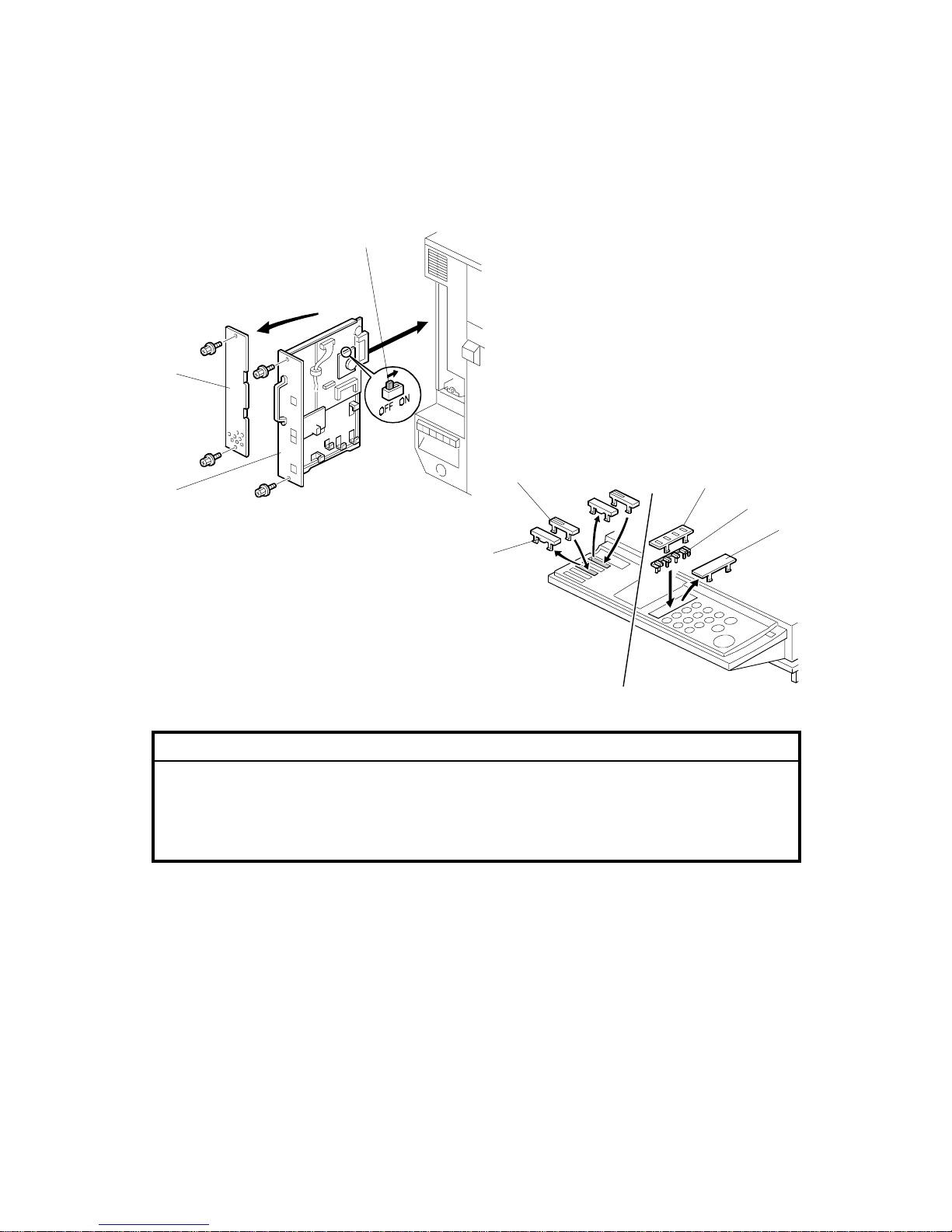
1.1.2 FAX OPTION INSTALLATION
!
CAUTION
Before installing this option, do the following:
1. Print out all data in the printer buffer.
2. Turn off the main switch and disconnect the power cord and the
network cable.
1. Remove the rear left cover plate [A] (! x 2).
2. Turn on the DIP switch [B] on the MBU board, then install the fax unit [C]
(! x 2).
NOTE: Make sure that the controlle r unit is installed when inserting the fax
unit. If the controller unit is installed after the fax unit has been
installed, this may cause poor connection between the fax unit and
controller unit.
3. Remove the cover key tops [D] and install key tops [E]/[F] and cover [G].
4. Attach the FCC decal (only for US/Canada) to the rear cover.
G307I501.WMF
G307I104.WMF
[A]
[C]
[B]
[D]
[F]
[G]
[E]
[D]
Page 6
21 December, 2001 FAX UNIT
1-3
Installation
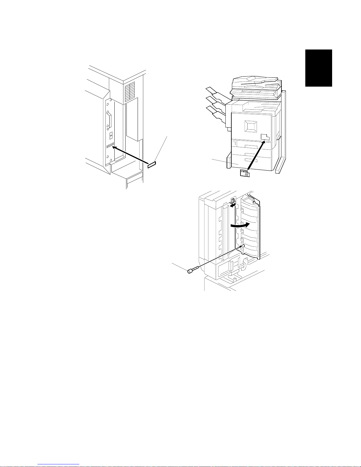
5. Attach the serial number decal [A] to the rear cover.
6. Attach the super G3 decal [B] as shown
7. If the ADF has been installed, insert the stamp cartridge [C] into the ADF as
shown.
8. Connect the telephone line to the “LINE” jack at the rear of the machine.
9. Plug in the machine and turn on the main power switch.
NOTE: The machine must be connected to a properly-grounded socket outlet.
10. Be sure to set the clock. (Date and time)
11. Enter service mode and program the serial number into the fax unit (SP3-102-
000). The serial number can be found on the serial number label (attached to
the machine in step 5).
G307I507.WMF
G307I105.WMF
G307I106.WMFWMF
[B]
[A]
[C]
Page 7
FAX UNIT 21 December, 2001
1-4
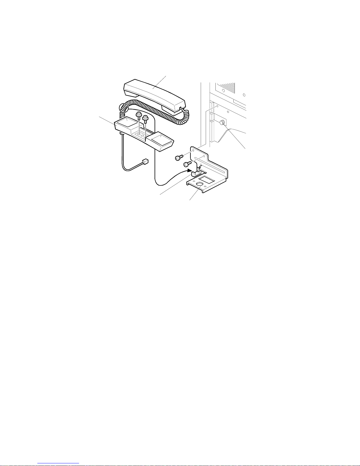
1.1.3 INSTALLING THE HANDSET
NOTE: The optional handset is for the U.S. model only.
1. Remove the thumb screw [A] on the left spacer.
2. Install the handset bracket [B] on the left arm (2 screws, 1 thumb screw).
3. Install the handset holder [C] on the bracket (2 screws).
4. Place the handset [D] with the handset cord resting on the cord holder [E] of
the bracket.
5. Connect the handset cord to the jack.
G307I114.WMF
[A]
[B]
[C]
[D]
[E]
Page 8
21 December, 2001 FAX UNIT OPTIONS
1-5
Installation
1.2 FAX UNIT OPTIONS
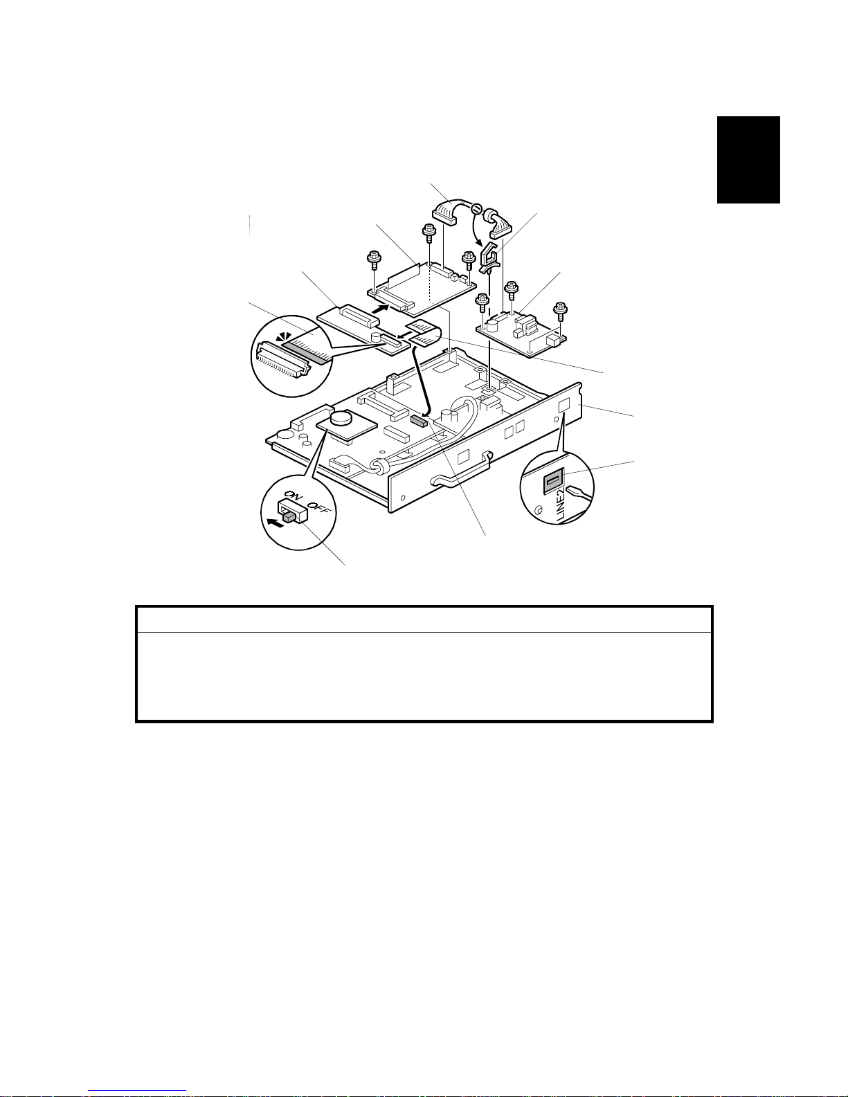
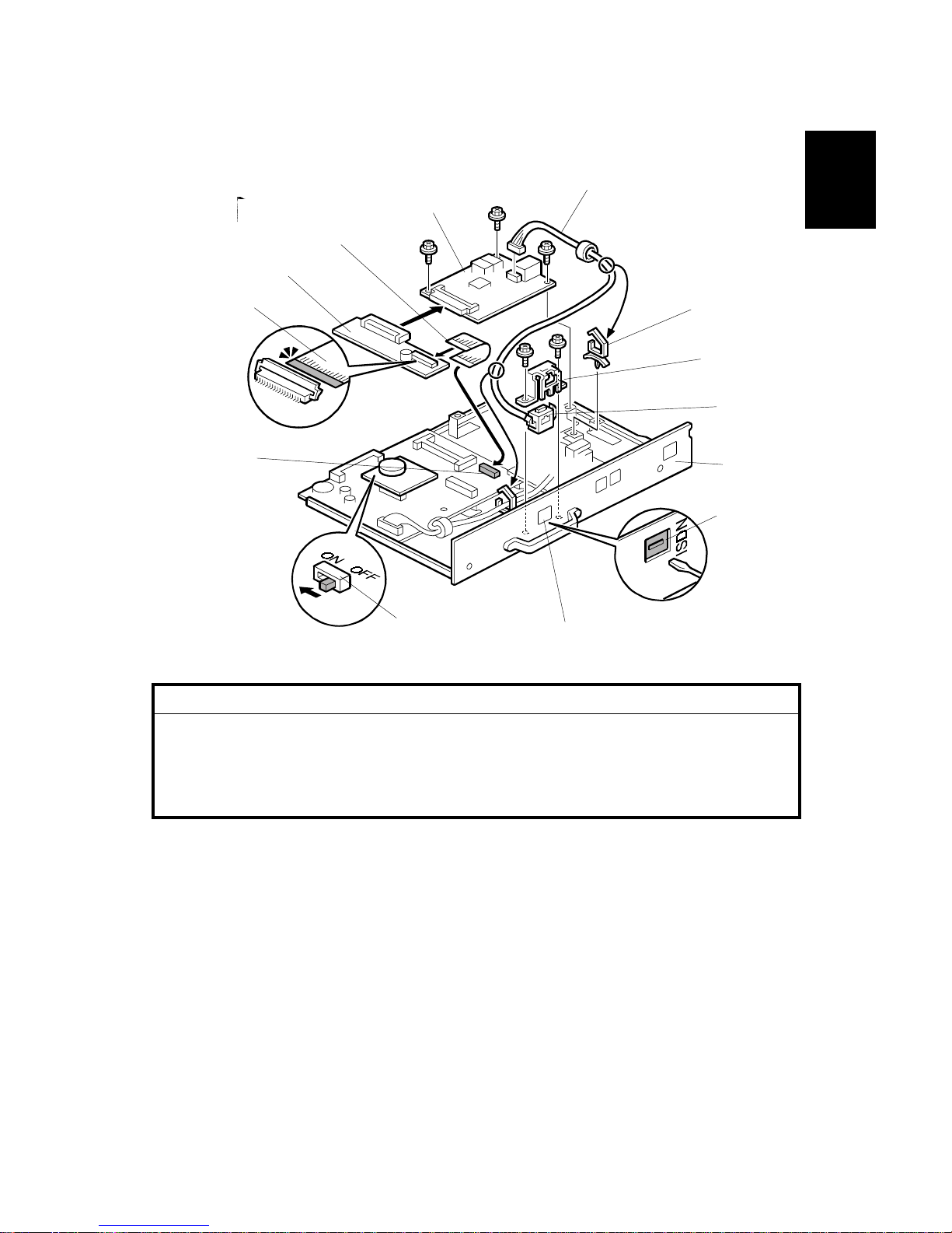
1.2.1 G3 INTERFACE UNIT INSTALLATION
!
CAUTION
Before installing this option, do the following:
1. Print out all data in the printer buffer.
2. Turn off the main switch and disconnect the power cord and the
network.
1. Remove the jack window (LINE2) [A] from the panel plate [B].
2. Install the G3 board [C] and NCU board [D] (3 screws each).
3. Attach the harness clamp [E].
4. Connect the harness [F] to the connectors on G3 and NCU boards (harness
clamp [E]).
5. Connect the flat cable [G] to the connector [H] on the FCU board.
6. Connect the I/F board [I] to the G3 board and connect the flat cable [G] to the
I/F board.
NOTE: When installing the fax unit and G3 unit simultaneously, turn on the DIP
switch [J] on the MBU board.
G307I511.WMF
[B]
[A]
[G]
[D]
[E]
[F]
[C]
[I]
[G]
[J]
[H]
Page 9
FAX UNIT OPTIONS 21 December, 2001
1-6
7. Remove the rear left cover plate [A] and install the fax unit [B] (2 screws each).
NOTE: Make sure that the controlle r unit is installed when inserting the fax
unit. If the controller unit is installed after the fax unit has been
installed, this may cause poor connection between the fax unit and
controller unit.
8. Connect the cable to the LINE2 jack, then plug in the machine and turn the
main switch on.
9. Attach the FCC/IC approval label to the machine near the ISDN jack (this step
is only for US/Canada).
10. Enter the service mode and set bit 1 of communication switch 16 to “1”, then
turn the main switch off and on.
11. Print the system parameter list and ensure that “SG3-V34” is listed as an
option.
12. Set up and program the items required for PSTN-2 communications.
G307I101.WMF
[A]
[B]
Page 10
21 December, 2001 FAX UNIT OPTIONS
1-7
Installation
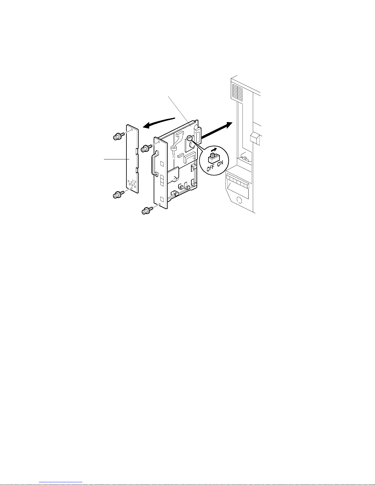
1.2.2 ISDN OPTION INSTALLATION
!
CAUTION
Before installing this option, do the following:
1. Print out all data in the printer buffer.
2. Turn off the main switch and disconnect the power cord and the
network cable.
1. Remove the jack window (ISDN) [A] from the panel [B].
2. Install the G4 unit [C] (3 screws) and harness clamp.
3. Connect the flat cable [D] to the connector [E] on the FCU board.
4. Connect the I/F board [F] to the G4 unit and connect the flat cable [D] to the I/F
board.
5. Attach the modular socket [G] to the bracket [H] and install the bracket (2
screws).
6. Connect the cable [I] to the G4 unit and route the cable (2 clamps [J]).
NOTE: When installing the fax unit and G4 unit simultaneously, turn on the DIP
switch [K] on the MBU board.
G307I521.WMF
[K]
[C]
[D]
[F]
[A]
[B]
[J]
[J]
[I]
[H]
[D]
[E]
[G]
Page 11
FAX UNIT OPTIONS 21 December, 2001
1-8
7. Remove the rear left cover [A] and install the fax unit [B] (! x 2 each).
NOTE: Make sure that the controller unit is installed when inserting the fax
unit.
If the controller unit is installed after the fax unit has been installed, this
may cause poor connection between the fax unit and controller unit.
8. Connect the cable to the ISDN jack, then plug in the machine and turn the main
switch on.
9. Attach the FCC/IC approval label to the machine near the ISDN jack (this step
is only for US/Canada).
10. Enter service mode and set bit 2 of communication switch 16 to "1". After that,
turn the main switch off and on.
11. Print the system parameter list and ensure that "G4" is listed as an option.
12. Set up and program the items required for ISDN communications. After setting
up the ISDN parameters, be sure to turn the main switch off and on.
G307I101.WMF
[A]
[B]
Page 12
21 December, 2001 FAX UNIT OPTIONS
1-9
Installation
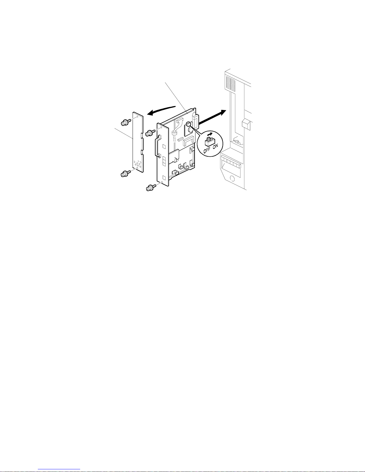
1.2.3 FAX FUNCTION UPGRADE UNIT INSTALLATION
!
CAUTION
Before installing this option, do the following:
1. Print out all data in the printer buffer.
2. Turn off the main switch and disconnect the power cord and the
network cable.
1. Turn on the DIP switch [A] on the fax function upgrade unit [B].
2. Attach the stand [C] to this unit.
3. Connect the fax function upgrade unit to CN621 and attach the stand to the
board.
4. Turn the main switch off and on.
5. Enter service mode and set bit 7 of system switch 1E to “1”
NOTE: When installing the fax unit and f ax function upgrade unit at the same time,
turn on the DIP switch [D] on the MBU board.
G307I103.WMF
[A]
[B]
[C]
[D]
Page 13
FAX UNIT OPTIONS 21 December, 2001
1-10
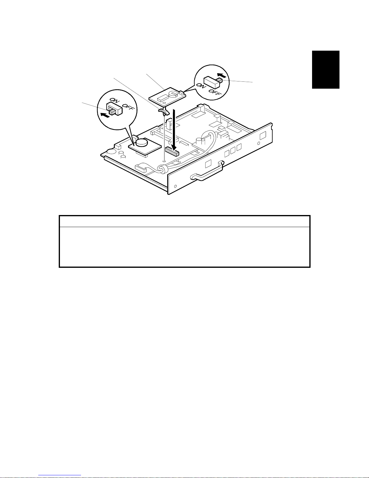
1.2.4 EXPANSION MEMORY INSTALLATION
!
CAUTION
Before installing this option, do the following:
1. Print out all data in the printer buffer.
2. Turn off the main switch and disconnect the power cord and the
network cable.
1. Slide the expansion memory [A] into the CN602 slot and tilt it down until it is
locked by the pin [B].
NOTE: When installing the fax unit and expansion memory at the same time, turn
on the DIP switch [C] on the MBU board.
G307I102.WMF
[A]
[C]
[B]
Page 14

21 December, 2001 ERROR CODES
2-1
Trouble-
shooting
2. TROUBLESHOOTING
2.1 ERROR CODES
If an error code occurs, retry the communication. If the same problem occurs, try to
fix the problem as suggested below. Note that some error codes appear only in the
error code display and on the service report.
Code Meaning Suggested Cause/A c ti on
0-00 DIS/NSF not detecte d w it hin
40 s of Start being pressed
• Check the line connection.
• Check the NCU - FCU connectors.
• The machine at the other end may be
incompatible.
• Replace the NCU or FCU.
• Check for DIS/NSF with an oscilloscope.
• If the rx signal is weak, there may be a bad line.
0-01 DCN received unexpectedly
• The other party is out of paper or has a jammed
printer.
• The other party pressed Stop during
communication.
0-03 Incompatible mode m at t he
other end
• The other terminal is incompat ible.
0-04 CFR or FTT not received
after modem training
• Check the line connection.
• Check the NCU - FCU connectors.
• Try changing the tx level and/or ca bl e equalizer
settings.
• Replace the FCU or NCU.
• The other terminal may be faulty ; try sending to
another machine.
• If the rx signal is weak or defective, there may be
a bad line.
Cross reference
• Tx level - NCU Par ameter 01 (PSTN)
• Cable equalizer - G 3 Switch 07 (PSTN)
• Dedicated Tx parameters - Section 4
0-05 Unsuccessful after modem
training at 2400 bps
• Check the line connection.
• Check the NCU - FCU connectors.
• Try adjusting the tx level and/or cable equalizer.
• Replace the FCU or NCU.
• Check for line problems.
Cross reference
• See error code 0-04.
Page 15

ERROR CODES 21 December, 2001
2-2
Code Meaning Suggested Cause/A c ti on
0-06 The other terminal did not
reply to DCS
• Check the line connection.
• Check the FCU - NCU connectors.
• Try adjusting the tx level and/or cable equalizer
settings.
• Replace the NCU or FCU.
• The other end may be defective or incompatible;
try sending to another machine.
• Check for line problems.
Cross reference
• See error code 0-04.
0-07 No post-message response
from the other end after a
page was sent
• Check the line connection.
• Check the FCU - NCU connectors.
• Replace the NCU or FCU.
• The other end may have jammed or run out of
paper.
• The other end user may have disconne ct ed t he
call.
• Check for a bad line.
• The other end may be defective; t ry sending to
another machine.
0-08 The other end sent RTN or
PIN after receiving a page,
because there were too
many errors
• Check the line connection.
• Check the FCU - NCU connectors.
• Replace the NCU or FCU.
• The other end may have jammed, or run out of
paper or memory space.
• Try adjusting the tx level and/or cable equalizer
settings.
• The other end may have a defective
modem/NCU/FC U; t r y sending to another
machine.
• Check for line problems and noise.
Cross reference
• Tx level - NCU Par ameter 01 (PSTN)
• Cable equalizer - G 3 Switch 07 (PSTN)
• Dedicated Tx parameters - Section 4
0-14
Non-standard post message
response code received
• Check the FCU - NCU connectors.
• Incompatible or defective remote terminal; try
sending to another machine.
• Noisy line: resend.
• Try adjusting the tx level and/or cable equalizer
settings.
• Replace the NCU or FCU.
Cross reference
• See error code 0-08.
Page 16

21 December, 2001 ERROR CODES
2-3
Trouble-
shooting
Code Meaning Suggested Cause/A c ti on
0-15 The other terminal is not
capable of specific
functions.
The other terminal is not capabl e of a ccepting the
following functions, or the other termin al ’s me mory
is full.
• Confidential rx
• Transfer function
• SEP/SUB/PWD/SID
0-16 CFR or FTT not detected
after modem training in
confidential or transfer mode
• Check the line connection.
• Check the FCU - NCU connectors.
• Replace the NCU or FCU.
• Try adjusting the tx level and/or cable equalizer
settings.
• The other end may have disconnect ed, or it may
be defective; try calling another machine.
• If the rx signal level is too low, there may be a
line problem.
Cross reference
• See error code 0-08.
0-17 Communication was
interrupted by pressing the
Stop key.
If the Stop key was not pressed and this error keeps
occurring, replace the operation panel.
0-20 Facsimile data not receiv ed
within 6 s of retraining
• Check the line connection.
• Check the FCU - NCU connectors.
• Replace the NCU or FCU.
• Check for line problems.
• Try calling another fax machine.
• Try adjusting the reconstruction time for the first
line and/or rx cable equaliz er set t ing.
Cross reference
• Reconstruction time - G3 Switch 0A, bit 6
• Rx cable equalizer - G3 Switch 07 (PSTN)
0-21 EOL signal (end-of-line)
from the other end not
received within 5 s of the
previous EOL signal
• Check the connections between the FCU, NCU,
& line.
• Check for line noise or other line pro bl ems.
• Replace the NCU or FCU.
• The remote machine may be defective or may
have disconnected.
Cross reference
• Maximum interval between EOLs and between
ECM frames - G3 Bit Switch 0A, bit 4
0-22 The signal from the other
end was interrupted for
more than the acceptable
modem carrier drop time
(default: 200 ms)
• Check the line connection.
• Check the FCU - NCU connectors.
• Replace the NCU or FCU.
• Defective remote terminal.
• Check for line noise or other line pro bl ems.
• Try adjusting the acceptable mode m carrier drop
time.
Cross reference
• Acceptable modem carrier drop time - G3 Sw it ch
0A, bits 0 and 1
Page 17

ERROR CODES 21 December, 2001
2-4
Code Meaning Suggested Cause/A c ti on
0-23 Too many errors during
reception
• Check the line connection.
• Check the FCU - NCU connectors.
• Replace the NCU or FCU.
• Defective remote terminal.
• Check for line noise or other line pro bl ems.
• Try asking the other end to adjust their tx level.
• Try adjusting the rx cable equalizer set t ing an d/ or
rx error criteria.
Cross reference
• Rx cable equalizer - G3 Switch 07 (PSTN)
• Rx error criteria - Communication Switch 02, bits
0 and 1
0-30 The other terminal did not
reply to NSS(A) in AI short
protocol mode
• Check the line connection.
• Check the FCU - NCU connectors.
• Try adjusting the tx level and/or cable equalizer
settings.
• The other terminal may not be comp atible.
Cross reference
• Dedicated tx parameters - Section 4
0-32 The other terminal sent a
DCS, which contained
functions that the receiving
machine cannot handle.
• Check the protocol dump list.
• Ask the other party to contact the manufacturer.
0-52 Polarity changed durin g
communication
• Check the line connection.
Retry communication.
0-70 The communication mode
specified in CM/JM was not
available
(V.8 calling and called
terminal)
• The other terminal did not have a co mpat ible
communication mode (e.g., t he ot her t erminal
was a V.34 data modem and not a fax mo dem.)
• A polling tx file was not ready at t he ot her
terminal when polling rx was in it iated from the
calling terminal.
0-74
The calling terminal fell back
to T.30 mode, because it
could not detect ANSam
after sending CI.
• The calling terminal coul d not det ect ANSam due
to noise, etc.
• ANSam was too short to detect.
• Check the line connection an d condition.
• Try making a call to another V.8/V. 34 fax.
0-75
The called terminal fell back
to T.30 mode, because it
could not detect a CM in
response to ANSam
(ANSam timeout).
• The terminal could not detect A NS am.
• Check the line connection an d condition.
• Try receiving a call from another V.8/V.34 fax.
0-76 The calling terminal fell back
to T.30 mode, because it
could not detect a JM in
response to a CM
(CM timeout).
• The called terminal could not detect a CM due to
noise, etc.
• Check the line connection an d condition.
• Try making a call to another V.8/V. 34 fax.
Page 18

21 December, 2001 ERROR CODES
2-5
Trouble-
shooting
Code Meaning Suggested Cause/A c ti on
0-77 The called terminal fell back
to T.30 mode, because it
could not detect a CJ in
response to JM
(JM timeout).
• The calling terminal could not det ect a JM due to
noise, etc.
• A network that has narrow bandwidth cannot
pass JM to the other end.
• Check the line connection an d condition.
• Try receiving a call from another V.8/V.34 fax.
0-79 The called terminal detected
CI while waiting for a V.21
signal.
Check for line noise or other line problems.
If this error occurs, the called terminal falls back to
T.30 mode.
0-80
The line was disconnected
due to a timeout in V.34
phase 2 – line probing.
0-81 The line was disconnected
due to a timeout in V.34
phase 3 – equalizer trainin g.
0-82 The line was disconnected
due to a timeout in the V.34
phase 4 – control channel
start-up.
0-83 The line was disconnected
due to a timeout in the V.34
control channel restart
sequence.
• The guard timer expired while starting these
phases. Serious noise, narrow ba ndw idth, or low
signal level can cause these errors.
If these errors happen at the transmitting t erminal:
• Try making a call at a later time.
• Try using V.17 or a slower modem using
dedicated tx parameters.
• Try increasing the tx level.
• Try adjusting the tx cable equalizer setting.
If these errors happen at the receiving t erminal:
• Try adjusting the rx cable equalizer set t ing.
• Try increasing the tx level.
• Try using V.17 or a slower modem if the same
error is frequent when receiving from multiple
senders.
0-84
The line was disconnected
due to abnormal signa li ng in
V.34 phase 4 – control
channel start-up.
• The signal did not stop within 1 0 s.
• Turn off the machine, then turn it back on.
• If the same error is frequent, replace the FCU.
0-85
The line was disconnected
due to abnormal signa li ng in
V.34 control channel restart.
• The signal did not stop within 1 0 s.
• Turn off the machine, then turn it back on.
• If the same error is frequent, replace the FCU.
0-86 The line was disconnected
because the other terminal
requested a data rate using
MPh that was not available
in the currently selected
symbol rate.
• The other terminal was incompatible.
• Ask the other party to contact the manufacturer.
0-87
The control channel started
after an unsuccessful
primary channel.
• The receiving terminal restarte d t he cont rol
channel because data recept ion in the primary
channel was not successful.
• This does not result in an error communication.
0-88
The line was disconnected
because PPR was
transmitted/received 9
(default) times within the
same ECM frame.
• Try using a lower data rate at the start.
• Try adjusting the cable equalizer setting.
2-10 The modem cannot enter tx
mode
• Replace the FCU.
2-11 Only one V.21 connection
flag was received
• Replace the FCU.
Page 19

ERROR CODES 21 December, 2001
2-6
Code Meaning Suggested Cause/A c ti on
2-12 Modem clock irregularity
• Replace the FCU.
2-13 Modem initialization error
• Turn off the machine, then turn it back on.
• Update the modem ROM.
• Replace the FCU.
2-20 Abnormal coding/deco ding
(cpu not ready)
• Replace the FCU.
2-23
JBIG compression or
reconstruction error
• Turn off the machine, then turn it back on.
• Replace the EXFUNC board if the error is
frequent.
2-24 JBIG ASIC error
• Turn off the machine, then turn it back on.
• Replace the EXFUNC board if the error is
frequent.
2-25 JBIG data reconstruction
error (BIH error)
2-26
JBIG data reconstruction
error (Float marker error)
2-27
JBIG data reconstruction
error (End marker error)
2-28 JBIG data reconstruction
error (Timeout)
• JBIG data error
• Check the sender’s JBIG function.
• Update the MBU ROM.
2-50 The machine resets itself for
a fatal FCU system error
• If this is frequent, update the ROM, or replace the
FCU.
2-51 The machine resets itself
because of a fatal
communication error
• If this is frequent, update the ROM, or replace the
FCU.
3-00 G4 interface board reset
• Replace the G4 interface board or FC U.
3-10 Disconnection during ISDN
G3 communication
• Check the other terminal and the ISDN line.
• The other terminal may have dia led a w rong
number.
3-11 Disconnection during ISDN
G4 communication
• Check the other terminal and the ISDN line.
3-20
A CSA signal was received
during ISDN G4
communication
• The operator at the other terminal may have
interrupted the communication.
3-21 A CSA signal was sent
during ISDN G4
communication, because t he
Stop key was pressed
• The local operator has interrupted t he
communication.
3-30 Mismatched specific ations
(rx capability)
• Check the receive capabilities re quest ed from the
other terminal.
4-01 Line current was cut
• Check the line connector.
• Check the connection between FCU and NCU.
• Check for line problems.
• Replace the FCU or the NCU.
4-10
Communication failed
because of an ID Code
mismatch (Closed Network)
or Tel. No./CSI mismatch
(Protection against Wrong
Connections)
• Get the ID Codes the same and/or the CSIs
programmed correctly, then resend.
• The machine at the other end may be defective.
Page 20

21 December, 2001 ERROR CODES
2-7
Trouble-
shooting
Code Meaning Suggested Cause/A c ti on
5-00 Data construction not
possible
5-01 Data reconstruction not
possible
5-10 DCR timer expired
• Replace the FCU.
5-20 Storage impossible becaus e
of a lack of memory
• Temporary memory shortage.
• Test the SAF memory.
• Replace the FCU or optional EXMEM board
5-21 Memory overflow
5-22 Mode table overflow after
the second page of a
scanned document
• Wait for the messages which are currently in the
memory to be sent or delete some files from
memory.
5-23 Print data error when
printing a substitute rx or
confidential rx messag e
• Test the SAF memory.
• Ask the other end to resend the message.
• Replace the FCU or optional EXMEM board.
5-24 Memory overflow after the
second page of a scanned
document
• Try using a lower resolution setting.
• Wait for the messages which are currently in the
memory to be sent or delete some files from
memory.
5-25 SAF file access error
• Replace the FCU or EXMEM board.
6-00 G3 ECM - T1 time out
during reception of facsim ile
data
6-01
G3 ECM - no V.21 signal
was received
6-02
G3 ECM - EOR was
received
• Try adjusting the rx cable equalizer.
• Replace the FCU or NCU.
6-04 G3 ECM - RTC not detected
• Check the line connection.
• Check connections from the NCU to the FCU.
• Check for a bad line or defective remote term inal.
• Replace the FCU or NCU.
6-05 G3 ECM - facsimile data
frame not received within 18
s of CFR, but there was no
line fail
• Check the line connection.
• Check connections from the NCU to the FCU.
• Check for a bad line or defective remote term inal.
• Replace the FCU or NCU.
• Try adjusting the rx cable equaliz er
Cross reference
• Rx cable equalizer - G3 Switch 07 (PSTN)
6-06 G3 ECM - coding/decoding
error
• Defective FCU.
• The other terminal may be defectiv e.
6-08 G3 ECM - PIP/PI N received
in reply to PPS.N ULL
• The other end pressed Stop during
communication.
• The other terminal may be defectiv e.
6-09 G3 ECM - ERR received
• Check for a noisy line.
• Adjust the tx levels of the communicating
machines.
• See code 6-05.
Page 21

ERROR CODES 21 December, 2001
2-8
Code Meaning Suggested Cause/A c ti on
6-10 G3 ECM - error frames still
received at the other end
after all communication
attempts at 2400 bps
• Check for line noise.
• Adjust the tx level (use NCU parameter 01 or the
dedicated tx parameter for that addres s).
• Check the line connection.
• Defective remote terminal.
6-21 V.21 flag detected during
high speed modem
communication
• The other terminal may be defectiv e or
incompatible.
6-22
The machine resets the
sequence because of an
abnormal handshake in the
V.34 control channel
• Check for line noise.
• If the same error occurs frequently, replace t he
FCU.
• Defective remote terminal.
6-99 V.21 signal not stopped
within 6 s
• Replace the FCU.
22-00 Original length exceeded the
maximum scan length
• Divide the original into more than one page.
• Check the resolution used for scanning. Lower
the scan resolution if possible.
• Add optional page memory.
22-01 Memory overflow while
receiving
• Wait for the files in the queue to be sent .
• Delete unnecessar y files from memory.
• Transfer the substitute reception files to an
another fax machine, if the machine’s printer is
busy or out of order.
• Add an optional SAF memory card or hard disk.
22-02 Tx or rx job stalled due to
line disconnection at the
other end
• The job started normally but did not finish
normally; data may or may not have been
received fully.
• Restart the machine.
22-04 The machine cannot store
received data in the SAF
• Update the ROM
• Replace the FCU.
23-00 Data read timeout during
construction
• Restart the machine.
• Replace the FCU
25-00 The machine software
resets itself after a fatal
transmission error occurred
• Update the ROM
• Replace the FCU.
F0-xx V.34 modem error
• Replace the FCU.
F6-8x SG3-V34 modem error
• Update the SG3-V34 modem ROM.
• Replace the SG3-V34 boar d.
• Check for line noise or other line pro bl ems.
• Try communicating another V.8/V.34 fax.
Page 22

21 December, 2001 ERROR CODES FOR THE ISDN OPTION
2-9
Trouble-
shooting
2.2 ERROR CODES FOR THE ISDN OPTION
The tables on the following pages show the error codes for the ISDN option.
The meaning of the numbers in the Action column is as follows.
1. Check Layer 1 signaling with a protocol analyzer to determine the cause of the
problem. This may require assistance from a G4 specialist.
2. Repeat the communication. If the problem does not repeat itself, the problem
was a temporary one caused by the user connecting the machine to another
interface. However, if the problem remains, there is a network problem.
3. There is a network problem.
4. There is a network problem. Do the following:
• Check the error bit rate of the network. If it is high, contact the network and
ask them to improve the line.
• Check the network speed (is it 56 or 64 kbps), and make sure that the bit
switch setting is correct. You may also use the dedicated transmission
parameters if this problem only occurs when dialing certain numbers.
• Check that the user dialed the correct number.
5. There is a network problem, or a problem in the machine at the other end.
6. There is a problem in the machine at the other end; ask a technician to check it.
7. The machine at the other end is not a Group 4 fax terminal.
8. The machine is not compatible with the machine at the other end. A
compatibility test is needed.
Error codes related to the errors detected by the FCU are listed in the service
manual of the main body.
Page 23

ERROR CODES FOR THE ISDN OPTION 21 December, 2001
2-10
2.2.1 D-CHANNEL LAYER MANAGEMENT
Code Probable Cause Action
7-00 Link reset 2
7-01 Link set-up failed because of time-o ut . 2
7-02 Link release failed because of ti me-out . 2
7-03 Link set-up parameter error 2
2.2.2 D-CHANNEL, LAYER 1
Code Probable Cause Action
7-10 T3 timeout (layer 1 activation error) 1
7-11 No connection on the S0 interface 1
7-12 Deactivated 1
2.2.3 D-CHANNEL LINK LAYER
Code Probable Cause Action
7-20 At the start of link set-up, the ma chi ne received an unsolicited S (F= 1). 2
7-21 At the start of link set-up, the ma chine received an unsolicited DM
(F=1).
2
7-22 At TEI release, the machine received an unsolicited U A (F=1). 2
7-23 At the start of link set-up, the ma chine received an unsolicited DM
(F=0).
2
7-24 At TEI release, the machine received an unsolicited U A (F=0). 2
7-25 SABME received at the start of network link set-up No error
7-26 N200 retransmission error for SABME 2
7-27 N200 retransmission error for DISC 2
7-28 N200 retransmission error for situation enquiry (RR) 2
7-29 N(R) sequence number error 3
7-30 N(S) sequence number error 3
7-31 FRMR received 3
7-32 Non-standard frame receiv ed 3
7-33 Abnormal frame length 3
7-34 N201 error; information field N in the I frame exceeded N201 3
7-35 T201 timeout; timeout whi le waiting for checking 3
7-36 T202 timeout; timeout whi le w aiting for ID assignment 3
Page 24
21 December, 2001 ERROR CODES FOR THE ISDN OPTION
2-11
Trouble-
shooting
2.2.4 D-CHANNEL NETWORK LAYER
Code Probable Cause Action
7-40 Insufficient mandatory information elements 3
7-41 Abnormal LI for a mandatory inf ormation element 3
7-42 T301 timeout; timeout while waiting for R:CONN 3
7-43 T303 timeout; timeout while waiting for R: CALL-PROC etc. 3
7-44 T304 timeout; timeout while waiting for R: CALL-PROC etc. 3
7-45 T305 timeout; timeout while waiting for R:REL 3
7-46 T308 timeout; timeout w hile waiting for R:REL-COMP 3
7-47 T310 timeout; timeout w hi le w aiting for R: ALERT etc. 3
7-48 T313 timeout; timeout w hile waiting for R:CONN-ACK 3
7-49 Internal error 3
7-51 Release call reference during communication 3
2.2.5 B-CHANNEL LINK LAYER
Code Probable Cause Action
7-60 T3 timeout; timeout while wait ing for flag 4
7-61 T3 timeout; timeout while wait ing for SABM during an incoming ca ll 4
7-62 T1 timeout x N2; timeout while waiting for UA after sending SABM 5
7-63
T1 timeout x N2; timeout whi le waiting for a response to a transmitt ed
S frame (P=1)
5
7-64 T1 timeout x N2; timeout while waiting for SABM or DISC after sending
FRMR
5
7-65 T1 timeout x N2; timeout whi le w aiting for a response to DISC 5
7-66 RNR x N2 (other end busy, RCB counter error) 5
7-67 Invalid (Ad) frame received 5
7-68 Invalid short frame received 5
7-69 Link reset error 5
7-70 FRMR received 5
7-71 Non-standard (Cn) frame receiv ed 5
7-72 An S or U frame having an information field was receive d 5
7-73 A frame longer than the maximum N1 length was received 5
7-74 An S or I frame having an N(R) error was received 5
7-75 CRC error 3
Page 25

ERROR CODES FOR THE ISDN OPTION 21 December, 2001
2-12
2.2.6 B-CHANNEL NETWORK LAYER
Code Probable Cause Action
7-80 A packet having an abnormal G FI was received 6
7-81 A packet was received that had a l ogi cal channel number different
from the logical channel be ing used for the communication
6
7-82 A packet containing a format error was receiv ed 6
7-83 A packet containing an LI error was receiv ed 7
7-84 A CN packet was received that had a PID different from 02 7
7-85 Unsupported packet type received 7
7-86 Abnormal or unsupported fac ility received 7
7-87 P(s) sequence number error 6
7-88 P(r) sequence number error 6
7-89 A reset using S:RQ or R:RI occurred 6
7-90 A restart using S:RQ or R:SI occurred 6
7-91 Call set-up err or; in reply to S:CR, R:CI was receiv ed to indicate
rejection of the call
7
7-92 T20 timeout; timeout while w ait ing for an SF packet 6
7-93 T21 timeout; timeout while w ait ing for a CC packet 6
7-94 T22 timeout; timeout while w ait ing for an RF packet 6
7-95 T23 timeout; timeout while w ait ing for a CF packet 6
7-96 T10 timeout; timeout while w ait ing for the first frame 6
2.2.7 TRANSPORT LAYER
Code Probable Cause Action
8-00 Invalid block received 8
8-01 TCC block received 8
8-02 TBR block received 8
8-05 TCR block; block format error 8
8-06 TCR block; block size paramet er LI error 8
8-07 TCR block; extended addressing LI error 8
8-08 TCR block; block size length error 8
8-10 TCA block; block format error 8
8-11 TCA block; Tx origin reference d ata in TCR disagreed with the addre ss
reference data in TCA
8
8-12 TCA block; octet 7 did not equal 0 8
8-13 TCA block; extended address ing LI error 8
8-14 TCA block; block size exceeded that set by TCR 8
8-15 TCA block; block size parameter LI error 8
8-20 TDT block; block format error 8
8-21 TDT block; octet 3 did not equal either 00 or 80(H) 8
8-22 TDT block; the end indicat or w as “Continue” even though there was no
field data
8
8-23 TDT block; an end block with no field data was received after an end
indicator of “End”
8
8-26 Timeout during state 0.2 8
8-27 Timeout during state 1.1 8
8-28 Timeout during state 0.3 8
Page 26

21 December, 2001 ERROR CODES FOR THE ISDN OPTION
2-13
Trouble-
shooting
2.2.8 SESSION LAYER
Code Probable Cause Action
8-30 Invalid frame received 8
8-31 RSSN received 8
8-32 CSA received 8
8-34 Calling terminal ident i fication error in CSS 8
8-35 Date and time error in CSS 8
8-36 Window size error in CSS 8
8-37 Service identification error in CSS 8
8-38 Session user data error in CSS 8
8-39 CSS rejected (new session rejected) 8
8-40 Called termin al identificatio n error in RSSP 8
8-41 Date and time error in RSSP 8
8-42 Date and time in RSSP was n ot t he same as that in CSS 8
8-43 Window size error in RSSP 8
8-44 Service identification error in RSSP 8
8-45 Session user data error in RSSP 8
8-47 Message synchronization error inside the CCU 8
8-48 Document task busy 8
8-50 Ti timeout; non-communicat ion surveillance timer (T.62) 8
8-51 T2 timeout; timeout while wait ing for a response (T.62) 8
8-52 T3 timeout; CSA timer timeout (T.62) 8
8-53 G4 board load timer timeout; calling side waited too long for a new
session
8
8-54 G4 board load timer timeout; calling side waited too long for transport
probability
8
8-55 G4 board load timer timeout; called side waited too long for S:RS SP 8
8-56 G4 board load timer timeout; document t r ansmission surveillance timer
timeout
8
8-57 G4 board load timer timeout; timeout whi le waiting for a user abort
request after a provider fail
8
Page 27

ERROR CODES FOR THE ISDN OPTION 21 December, 2001
2-14
2.2.9 DOCUMENT LAYER
Code Probable Cause Action
8-60 T.62 coding format error (LI error) 8
8-61 A mandatory PI was absent, or the LI for a man dat ory PI was 0 8
8-62
Calling/called terminal identification LI was different from that specified
by F.184 (LI = 24)
8
8-63 The LI for session user data exceeded the maximum value (512) 8
8-64 The LI for CDUI was not 0 8
8-65 Checkpoint and document reference n umbers LI error, or they were
not in T.61 (ASCII) coding
8
8-66 The checkpoint reference nu mber differed from the expected value 8
8-70 RDGR received 8
8-71 A non-standard PDU was rece ived while in calling mode 8
8-72 A non-standard PDU was rece ived while in called mode 8
8-73 Abnormal PDU receiv ed while in calling state ds1 8
8-74 15 consecutive CDCL signals received 8
8-75 Session window size control error (size not equal to 0) 8
8-76 Internal error 8
2.2.10 PRESENTATION LAYER
Code Probable Cause Action
8-80 X.209 coding error in session user data (LI error) 8
8-81 PV error in session user data 8
8-82 PI error in session user data 8
8-83 The capabilities in the session user data of CDS/CDC were not the
same as those in RDCLP
8
8-84 X.209 coding error in the DP (LI error) 8
8-85 X.209 coding error in the SLD (document descriptor/page descriptor)
(LI error)
8
8-86 SLD object type absent 8
8-87 PI error in the SLD (document descriptor/ page descriptor) 8
8-88
The capabilities in the SLD (do cument descriptor/page descriptor) are
duplicated or are not the same as thos e in RDCLP
8
8-89 No document descriptor at the start of the document 8
8-90 No page descriptor at the start of the page 8
8-91 Page descriptor PV error 8
8-92 X.209 coding error in the TU (LI error) 8
8-93 The TU was absent 8
8-94 PV error in the TU 8
8-95 TI error 8
8-96 X.209 coding nest level >> 8, or an LI form error 8
8-97 CDPB/CDE received while TU/TI not yet completed, or an unexpected
PDU was received while analyzing an SLD
8
Page 28

21 December, 2001 FAX SC CODES
2-15
Trouble-
shooting
2.3 FAX SC CODES
2.3.1 OVERVIEW
When the FCU detects a Fax SC Code condition other than SC1201 and SC1207,
it resets itself automatically (default setting). This initializes the FCU without
erasing files in the SAF memory or resetting the switches.
NOTE: For details on Fax SC Codes 1201 and 1207, refer to the following
sections.
If bit 7 of System Switch 1F is changed to “1”, when the FCU detects a Fax SC
Code condition, it displays the code on the display and stops working until the fax
unit is initialized using one of the following methods:
• Hold down the “7” and “9” keys for more than 10 s.
• Turn off the main power switch and turn it back on.
2.3.2 SC1201
When the FCU detects an unrecoverable error in the SRAM, which requires a
complete SRAM initialization, the fax unit displays this SC Code and stops.
There is no way to recover from this error condition without a complete SRAM
initialization (all the user and service programmed data will be erased).
The possible causes are:
• SRAM backup battery defect, or SW1 on the MBU is at the “OFF” position
• SRAM on the MBU has a physical defect
• Flash memory card connection was loose
2.3.3 SC1207
This is the same as SC1201 except the error location is the SRAM on the Fax
Function Upgrade board.
The possible causes are:
• SRAM backup battery defect, or SW1 on the Fax Function Upgrade board is at
the “OFF” position.
• SRAM on the Fax Function Upgrade board has a physical defect.
• The Fax Function Upgrade board connection was loose.
Page 29

FAX SC CODES 21 December, 2001
2-16
2.3.4 FAX SC CODE TABLE
SC Code Description
Suggested
Action
Sys Switch
1F bit 7 = 0
Sys Switch
1F bit 7 = 1
1101 FCU error Initialize the fax unit.
(See section 2.3.1.for
the initialization
procedure)
Automatic
reset
1201 Unrecoverable FCU -
SRAM error
Refer to section 2.3.2.
“Service Call”
display
1207
Unrecoverable Fax
Function Upgrade SRAM error
Refer to section 2.3.3.
“Service Call”
display
1299
1305
1310
1311
1312
1401
1405
Software error Initialize the fax unit.
Automatic
reset
SC Code
display
Page 30

21 December, 2001 ISDN TEST FUNCTIO N
2-17
Trouble-
shooting
2.4 ISDN TEST FUNCTION
2.4.1 LEDS
There are four LEDs on the G4 board. These LEDs show the status of the
machine.
LED 1 LED 2 LED 3 LED 4
Initial Settings O=ON, --=OFF
Initial check (if the flash RO M i s updated) O O O O
Handshaking with the FCU ready O O -- --
Standby Mode
Ready to communicate -- -- -- --
Communication
Layer 1 activated -- -- -- O
Link setup -- -- O O
B channel 1 connected -- O O O
B channel 2 connected O -- O O
Page 31

ISDN TEST FUNCTION 21 December, 2001
2-18
2.4.2 BACK-TO-BACK TEST
To make a back-to-back test, you need:
• Two machines, one with the CiG4 board (G4 board used in the FX4, FR4,
Adam, NAD, Stinger, and Russian) and the other with the SiG4 board (G4
board used with the Schmidt 3, S4, J-CF, and Kaiser 1).
• Cross rosette
NOTE: You cannot make a back-to-back test using two SiG4 machines.
The procedure is as follows.
1. Switch off the machines
2. Connect two machines back-to-back using a cross rosette as follows.
3. Make the following bit switch adjustments:
• In the machine acting in NT mode (CiG4 board), set bits 0 and 1 of G4
parameter switch 0D to 1.
• In the machine acting in TE mode (SiG4 board) set bit 0 of G4 parameter
switch 0D to 0 and bit 1 to 1.
4. Reset the machines by switching them off, waiting a few seconds, then
switching back on.
5. Place a document in one of the machines, dial a number, then press Start.
6. After you have finished the test, set bits 0 and 1 of G4 parameter switch 0D
back to 0, then reset the machine.
NOTE: The following cannot be tested using this procedure:
• ISDN G3 communication
• Point to Multi (Like a broadcasting test, from one point to many places.)
1
2
3
4
5
6
7
8
1
2
3
4
5
6
7
8
1
2
3
4
5
6
7
8
Cross Rosette
Machine A Machine B
G307T601.WMF
Page 32

21 December, 2001 SERVICE PROG RAM MODE
3-1
Service
Tables
3. SERVICE TABLES
!
CAUTION
Never turn off the main power switch when the power LED is lit or flashing.
To avoid damaging the hard disk or memory, press the operation power
switch to switch the power off, wait for the power LED to go off, and then
switch the main power switch off.
NOTE: The main power LED lights or flashes while the platen cover or ARDF is
open, while the main machine is communicating with a facsimile machine
or the network server, or while the machine is accessing the hard disk or
memory for reading or writing data.
3.1 SERVICE PROGRAM MODE
3.1.1 SERVICE PROGRAM MODE OPERATION
The service program (SP) mode is used to check electrical data, change modes,
and adjust values.
Entering and Exiting SP mode
"
1. Press the Clear Mode key.
#$%
2. Use the keypad to enter “107”.
&
3. Hold down Clear/Stop for at least 3 seconds.
Fax SP
4. On the touch-panel, press Fax SP.
Exit
5. Press Exit twice to return to the copy window.
Page 33

SERVICE PROGRAM MODE 21 December, 2001
3-2
SP Mode Button Summary
Here is a short summary of the touch-panel buttons.
!!!!
Opens all SP groups and sublevels.
""""
Closes all open groups and sublevels and restores the init ial SP mode display.
####
Not used for the Fax SP mode.
$$$$
Enter the SP mode directly w ith t he number keys if you know the SP number and t hen
press '. (SP Mode must be highlighted before you can enter the number. Just press SP
Mode if it is not highlight ed. )
%%%%
Press twice to leave the SP mod e ret urn t o t he copy window to resume normal operation.
&&&&
Press any Group number to open a list o f SP mode s and titles for that group. For
example, to open the SP mode list for SP1-nnn, press Group1. If an SP has sublevel s,
click the appropriate button t o expand the list.
''''
Press to scroll the display to t he previous or next group.
((((
Press to scroll to the previous or next display in segments the size of the screen display
(page).
))))
Press to scroll the display t o t he previous or next line, line by line.
****
Press to move to the highlig ht t o t he previous or next selection in the list on t he left.
‡@ ‡A ‡B ‡C ‡D
‡E ‡F
‡G
‡H
‡I
G307S902.WMF
Page 34

21 December, 2001 SERVICE PROG RAM MODE
3-3
Service
Tables
Switching Between SP Mode and Copy Mode for Test Printing
1) In the SP mode, select the test print and then press Copy Window.
2) Use the copy window (copier mode), to select the appropriate settings
(paper size, etc.) for the test print.
3) Press Start ( to execute the test print.
4) Press SP Mode (highlighted) to return to the SP mode screen and repeat
from step 1.
Selecting the Program Number
Program numbers have two or three levels.
1. Before you begin, refer to the Service Tables to find the SP that you want to
adjust. (☛ 3.1.2)
2. Click the Group number on the left side SP Mode window that contains the SP
that you want to adjust.
3. Use the scrolling buttons in the center of the SP mode window to display the
SP number that you want to open, then press that number to expand the list.
4. Use the center touch-panel buttons to scroll to the number and title of the item
that you want to set and press. The small entry box on the right is activated and
displays the default or the current setting below.
Refer to the Service Tables for the range of allowed settings. (☛ 3.1.2)
1. To enter a setting:
• Press ! to toggle between plus and minus, then use the keypad to enter the
appropriate number. The number you enter writes over the previous setting.
• Press ' to enter the setting. (If you enter a number that is out of range, the
key press is ignored.)
• When you are prompted to co mplete the selection, press Yes.
2. When you are finished, press Exit twice to return to the copy window.
‡@ ‡A ‡B ‡C ‡D
‡E ‡F
‡G
‡H
‡I
G307S902.WMF
Page 35

SERVICE PROGRAM MODE 21 December, 2001
3-4
3.1.2 SERVICE PROGRAM MODE TABLES
SP1-XXX (Bit Switches)
☛ Section 3.2 Bit Switches
1
Mode No. Function
System Switch101
001 – 032 00 – 1F Change the bit switches for syst em settings
for the fax option
☛ Section 3.2 Bit Swit ches
Scanner Switch102
001 – 016 00 – 0F Change the bit switches for scanner
settings for the fax option
☛ Section 3.2 Bit Swit ches
Printer Switch103
001 – 016 00 – 0F Change the bit switches for print er set t i ngs
for the fax option
☛ Section 3.2 Bit Swit ches
Communication Switch104
001 – 032 00 – 1F Change the bit switches for c ommunication
settings for the fax option
☛ Section 3.2 Bit Swit ches
G3-1 Switch105
001 – 016 00 – 0F Change the bit switches for th e prot ocol
settings of the standard G3 board ☛
Section 3.2 Bit Switches
G3-2 Switch106
001 – 016 00 – 0F Change the bit switches for th e prot ocol
settings of the optional extra G 3 board
☛ Section 3.2 Bit Swit ches
G4 Internal Switch108
001 – 032 00 – 1F
Change the bit switches for the optional
ISDN ☛
Section 3.2 Bit Switches
G4 Parameter Switch109
001 – 016 00 – 0F Change the bit switches for the optional
ISDN
☛ Section 3.2 Bit Swit ches
SP2-XXX (RAM Data)
2
Mode No. Function
RAM Read/Write101
001 Change RAM data for the fax board dire ct ly.
☛ Section 3.5 Service RAM Addresses
Memory Dump
001 G3-1 Memory Dump
Print out RAM data for the fax board. ☛
Section 3.5 Service RAM Addre sses
002 G3-2 Memory Dump Print out RAM data for the optional ext r a G 3
board.
102
004 G4 Memory Dump Print out RAM data for the SiG4 board.
Page 36

21 December, 2001 SERVICE PROG RAM MODE
3-5
Service
Tables
2
Mode No. Function
G3-1 NCU Parameters103
001 – 023 CC, 01 – 22
NCU parameter settings for the standard
G3 board. ☛ Section 3.3 NCU Parameters
G3-2 NCU Parameters104
001 – 023 CC, 01 – 22
NCU parameter settings for the optional G3
board. ☛ Section 3.3 NCU Parameters
SP3-XXX (Tel Line Settings)
3
Mode No. Function
Service Station
001 Fax Nu mber Enter the fax number of the service stati on.
101
002 Select Li ne Select the line type.
Serial Number102
000 Enter the fax un it ’s serial number.
PSTN-1 Port Settings
001 Select Li ne Select the line type setting for the G3-1 line.
If the machine is installed o n a PABX line,
select “PABX”, “PABX(GND)” or
“PABX(FLASH)”.
002 PSTN Acc ess Number Enter the PSTN access number for the
G3-1 line.
003
Memory Lock
Disabled
If the customer does not want to receive
transmissions using Memory Lock on this
line, turn this SP on.
103
004 Transmission
Disabled
If you turn this SP on, the machine does not
send any fax messages on the G3-1 line.
PSTN-2 Port Settings
001 Select Li ne Select the line setting for the G3-2 (optional
extra G3) line. If the machine is i nst al led on
a PABX line, select “PABX”, “PABX(GN D) ”
or “PABX(FLASH)”.
002 PSTN Acc ess Number Enter the PSTN access number for the G3-
2 line.
003
Memory Lock
Disabled
If the customer does not want to receive
transmissions using Memory Lock on this
line, change this SP to on.
104
004 Transmission
Disabled
If you turn this SP on, the machine does not
send any fax messages on the G3-2 line.
ISDN Port Settings
001 Select Line Select the line setting for the ISDN line. If
the machine is installed on a PABX line,
select “PABX”.
002 PSTN Acc ess Number Enter the PSTN access number for ISD N
line.
003 Memory Lock
Disabled
If the customer does not want to receive
transmissions using Memory Lock on this
line, change this SP to on
106
004 Transmission
Disabled
If you turn this SP on, the machine does not
send any fax messages on the IS D N li ne.
Page 37

SERVICE PROGRAM MODE 21 December, 2001
3-6
SP4-XXX (ROM Versions)
4
Mode No. Function
101 001 FCU ROM Version Displays the FC U ROM version.
102 001 Error Codes Displays the latest 64 fax error codes.
103 001 G3-1 ROM Version Displays the G3-1 modem version.
104 001 G3-2 ROM Version Displays the G3-2 modem version.
106 001 G4 ROM Version Displays the G4 (ISDN) ROM v ersion.
107 001 Charge ROM Version Not used.
SP5-XXX (Initializing)
5
Mode No. Function
Initialize SRAM101
000
Initializes the bit sw itches and user
parameters, user data in the SRAM, files i n
the SAF memory, and clock.
Erase All Files102
000 Erases all files stored in the SAF me mory .
Reset Bit Switches103
000 Resets the bit switches and user
parameters.
Factory setting104
000 Resets the bit switches and user
parameters, user data in the SRAM and
files in the SAF memory.
Delete All Speed Dials
001 Speed Dials Enabled
200 speed dials and 1000 quic k d ia ls are
available when the Fax Funct i on Upgrade
Unit is installed.
105
002 Speed Dials Disabled 1200 quick dials (but no speed dials) are
available when the Fax Funct i on Upgrade
Unit is installed.
SP6-XXX (Reports)
6
Mode No. Function
System Parameter List101
000
Touch the “ON” button to print t he system
parameter list.
Service Monitor Report102
000
Touch the “ON” button to print the service
monitor report.
G3 Protocol Dump List
001 G3 All
Communications
Prints the protocol dump list o f all
communicatio ns for all G3 lines.
103
002 G3-1 (All
Communications)
Prints the protocol dump list o f all
communications for the G3-1 li ne.
Page 38

21 December, 2001 SERVICE PROG RAM MODE
3-7
Service
Tables
6
Mode No. Function
003
G3-1 (1
Communication)
Prints the protocol dump list o f the last
communication for the G3-1 line.
004 G3-2 (All
Communications)
Prints the protocol dump list o f all
communications for the G3-2 li ne.
103
005 G3-2 (1
Communication)
Prints the protocol dump list o f the last
communication for the G3-2 line.
G4 Protocol Dump List
001 Dch + Bch 1
002 Dch
003 Bch 1 Link Layer
004 Dch Link Layer
005 Dch +Bch 2
104
006 Bch 2 Link Layer
Prints the protocol dump list s for the G 4
line.
All Files print out105
000
Prints out all the user files in the SAF
memory, including confidential messages.
NOTE: Do not use this function, unless
the customer is having trouble
printing confidential messages or
recovering files stored using the
memory lock feature.
Journal Print out
001 All Journals
The machine prints all the co mmunication
records on the report.
106
002 Specified Date The machine prints all communication
records after the specified date.
Log List Print out
001 All log files
002 Printer
003 SC/TRAP Stored
004 Decompression
005 Scanner
006 JOB/SAF
007 Reconstruction
008 JBIG
009 FAX Driver
010 G3CCU
011 FAX Job
012 CCU
107
013 Scanner Condition
These log print out functions are for
designer use only.
011 JBIG
012 Fax Driver
013 G3CCU
107
014 Fax Job
These log print out functions are for
designer use only.
Page 39

SERVICE PROGRAM MODE 21 December, 2001
3-8
SP7-XXX (Test Modes)
These are test modes for PTT approval.
7
Function
101 G3-1 Modem Tests
102 G3-1 DTMF Tests
103 Ringer Test
104 G3-1 V34 (S2400baud)
105 G3-1 V34 (S2800baud)
106 G3-1 V34 (S3000baud)
107 G3-1 V34 (S3200baud)
108 G3-1 V34 (S3429baud)
109 Recorded Message Test
110 G3-2 Modem Tests
111 G3-2 DTMF Tests
112 G3-2 V34 (S2400baud)
113 G3-2 V34 (S2800baud)
114 G3-2 V34 (S3000baud)
115 G3-2 V34 (S3200baud)
116 G3-2 V34 (S3429baud)
124 IG3-1 Modem Tests
125 IG3-1 DTMF Tests
126 IG3-1 V34 (S2400baud)
127 IG3-1 V34 (S2800baud)
128 IG3-1 V34 (S3000baud)
129 IG3-1 V34 (S3200baud)
130 IG3-1 V34 (S3429baud)
131 IG3-2 Modem Tests
132 IG3-2 DTMF Tests
133 IG3-2 V34 (S2400baud)
134 IG3-2 V34 (S2800baud)
135 IG3-2 V34 (S3000baud)
136 IG3-2 V34 (S3200baud)
137 IG3-2 V34 (S3429baud)
Page 40

21 December, 2001 BIT SWITCHES
3-9
Service
Tables
3.2 BIT SWITCHES
!
WARNING
Do not adjust a bit switch or use a setting that is described as “Not used”,
as this may cause the machine to malfunction or to operate in a manner
that is not accepted by local regulations. Such bits are for use only in other
areas, such as Japan.
NOTE: Default settings for bit switches are not listed in this manual. Refer to the
System Parameter List printed by the machine.
3.2.1 SYSTEM SWITCHES
System Switch 00 SP No. 1-101-001
No FUNCTION COMMENTS
0
Dedicated transmission
parameter programming
0: Disabled 1: Enabled
Set this bit to 1 before changing a ny dedicated
transmission parameters.
Reset this bit to 0 after programmin g dedicated
transmission parameters.
1 Confidential RX message print
out without the password.
0: Disabled 1: Enabled
1: Confidential RX messages can be printed out
without the password. Use this bit if the customer
forgot the password for the confident ial
messages. Reset this bit to 0 after printing
confidential RX messa ges.
Technical data printout on the
Journal
0: Disabled
1: Enabled
1: Instead of the personal name, the f ollowing data
are listed on the Journal for each G3
communication.
2
e.g. 0000 32V34 288/264 L0100 03 04
(1) (2)(3) (4) (5) (6) (7) (8)
(1): EQM value (Line quality data). A larger number means more errors.
(2): Symbol rate (V.34 only)
(3): Final modem type used
(4): Starting data rate (for example, 288 means 28.8 kbps)
(5): Final data rate
(6): Rx revel (refer to the note after this table for how to read the rx level)
(7): Total number of error lines that occurred during non-ECM reception.
(8): Total number of burst error lines that occurred during non-ECM reception.
Note:
EQM and rx level are fixed at “FFFF” in tx mode.
The seventh and eighth numbers are fixed at “00” for transmission records and
ECM reception records.
Page 41

BIT SWITCHES 21 December, 2001
3-10
System Switch 00 SP No. 1-101-001
No FUNCTION COMMENTS
2 Rx level calculation
Example: 0000 32 V34 288/264 L 01 00
03 04
The four-digit hexadecimal value (N) after “L” indicates the rx level.
The high byte is given first, followed by the low
byte. Divide the deci mal value of N by -
16 to get the rx level.
In the above example, the deci mal value of N (= 0100 [H]) is 256.
So, the actual rx level is 256/-16 = -16 dB
3-4 Not used Do not change the settings.
5 G3/G4 communication
parameter display
0: Disabled
1: Enabled
This is a fault-finding aid. The LCD shows the key
parameters (see below). This is normally disabled
because it cancels the CSI d isp lay for the user.
Be sure to reset this bit to 0 after testing.
6 Protocol dump list output after
each communication
0: Off
1: On
This is only used for commun icat i on
troubleshooting. It shows the content of the
transmitted facsimile prot ocol signals. Always reset
this bit to 0 after finishing testing.
If system switch 09 bit 6 is at “1”, t he list is only
printed if there was an error during the
communication.
7 Not used Do not change the setting.
G3 Communication Parameters
Modem rate 336: 33600 bps 168: 16800 bps
312: 31200 bps 144: 14400 bps
288: 28800 bps 120: 12000 bps
264: 26400 bps 96: 9600 bps
240: 24000 bps 72: 7200 bps
216: 21600 bps 48: 4800 bps
192: 19200 bps 24: 2400 bps
Resolution S: Standard (8 x 3.85 dots/mm)
D: Detail (8 x 7.7 dots/mm)
F: Fine (8 x 15.4 dots/mm)
SF: Superfine (16 x 15.4 dots/ mm)
21: Standard (200 x 100 dpi)
22: Detail (200 x 200 dpi)
44: Superfine (400 x 400 dpi)
Compression mode MMR: MMR compression
MR: MR compression
MH: MH compression
JBO: JBIG compression (Optional mode)
JBB: JBIG compression (Basic mode)
Communication
mode
ECM: With ECM
NML: With no ECM
Width and
reduction
A4: A4 (8.3"), no reduction
B4: B4 (10.1"), no reduction
A3: A3 (11.7"), no reduction
Page 42

21 December, 2001 BIT SWITCHES
3-11
Service
Tables
I/O rate 0: 0 ms/line 10: 10 ms/line
25: 2.5 ms/line 20: 20 ms/line
5: 5 ms/line 40: 40 ms/line
Note:
“40” is displayed while receiving a fax message using AI short
protocol.
G4 Communication Parameters
Compression mode MMR: MMR compression
MR: MR compression
MH: MH compression
Resolution
21: Standard (200 x 100 dpi)
22: Detail (200 x 200 dpi)
44: Superfine (400 x 400 dpi)
Width and
reduction
A4: A4 (8.3"), no reduction
B4: B4 (10.1"), no reduction
A3: A3 (11.7"), no reduction
Transfer
T: Transfer
- : Other
Confidential C: Confidential
- : Other
Other parameters
The following information is shown in 6-bit format. Bit 1 is the first
bit from the left, and bit 6 is at the right end.
Bit 1 - Smoothing 0: Off, 1: On
(Smoothing is disabled in halftone mode.)
Bit 2 - CIL printing 0: On, 1: Off
Bit 3 - Not used
Bit 4 - mm/inch conversion 0: Off, 1: On
Bit 5 - Engine type 0: mm, 1: inches
Bit 6 - Document resolution unit 0: mm, 1: inches
System Switch 01 - Not used (Do not change the factory settings.)
System Switch 02 SP No. 1-101-003
No FUNCTION COMMENTS
0-3 Not used Do not change the settings.
4
File retention time
0: Depends on User Parameter
24 [18(H)]
1: No limit
1: A file that had a communication error will not be
erased unless the communication is successful.
5 Not used Do not change the settings.
Page 43

BIT SWITCHES 21 December, 2001
3-12
System Switch 02 SP No. 1-101-003
No FUNCTION COMMENTS
6
7
Memory read/write by RDS
Bit 7 6 Setting
0 0 Always disabled
0 1 User selectable
1 0 User selectable
1 1 Always enabled
(0,0): All RDS systems are alway s locked out.
(0,1), (1,0): Normally, RDS systems are locked out,
but the user can temporarily swit ch RDS on to allow
RDS operations to take place. RDS will
automatically be locked out again after a certain
time, which is stored in System Switch 03. Note that
if an RDS operation takes pl ace, RDS will not switch
off until this time limit has expired.
(1,1): At any time, an RDS system can access t he
machine.
System Switch 03 SP No. 1-101-004
No FUNCTION COMMENTS
0
to
7
Length of time that RDS is
temporarily switched on when
bits 6 and 7 of System Switch
02 are set to “User selectable”
00 - 99 hours (BCD).
This setting is only valid if bits 6 and 7 of System
Switch 02 are set to “User selectable”.
The default setting is 24 hours.
System Switch 04 SP No. 1-101-005
No FUNCTION COMMENTS
0-2 Not used Do not change the settings.
3 Printing dedicated tx
parameters on Quick/Speed
Dial Lists
0: Disabled
1: Enabled
1: Each Quick/Speed d ia l number on the list is
printed with the dedicated tx para meters (10
bytes each).
The first 10 bytes of data are the programmed
dedicated tx parameters; 34 byt es of data are
printed (the other 24 bytes have no use for service
technicians).
4 Not used Do not change the setting.
Page 44

21 December, 2001 BIT SWITCHES
3-13
Service
Tables
System Switch 04 SP No. 1-101-005
No FUNCTION COMMENTS
5 Memory file transfer operation
0: User level
1: Service level
If the machine is unable to print fax messages due
to a mechanical proble m, change this bit to 0 to
transfer all messages in the memory (including
confidential rx messages) to an another terminal.
Always reset this bit to 1 after transfer. However,
this bit can be left at 0, if the cust omer’s keyoperators want to transfer the files thems elves.
This machine does not support the confidential rx.
Procedure
1. Enter service mode and change this bit to 0.
2. Exit the service mode.
3. Enter the key-operator mode, and select ‘Keyoperator settings’.
4. Choose ‘03’ and specify a dest i nat ion for the
machine to transfer all the files to.
5. Press ‘Start’.
6. After the machine transfers the memory files,
enter the service mode and reset this b it t o 1.
Otherwise, anybody who knows how t o ent er the
key-operator mode can transfer confidential
messages.
6 G3 CSI/G4 Terminal ID
programming level
0: User level
1: Service level
1: The CSI and Terminal I D can only be
programmed by a technician (in the user tool s).
The Terminal ID can only be programmed if a
Group 4 option is installed.
This machine does not have a G roup 4 option.
7 Telephone line type
programming mode
0: User level
1: Service level
1: Telephone line type selection (choosing tone dia l
or pulse dial) can only be program med by a
technician (in the user tools).
System Switch 05 - Not used (Do not change the factory settings.)
System Switch 06 SP No. 1-101-007
No FUNCTION COMMENTS
0
to
7
Margin setting for Create
Margin Transmission
71 to 99 (BCD) %. This setting determines the
reduction ratio when the user uses the Creat e
Margin Transmission feature.
Default setting:1001 0011 (93%)
System Switch 07 - Not used (Do not change the factory settings.)
System Switch 08 - Not used (Do not change the factory settings.)
Page 45

BIT SWITCHES 21 December, 2001
3-14
System Switch 09 SP No. 1-101-010
No FUNCTION COMMENTS
0 Addition of image data from
confidential transmissions on
the transmission result report
0: Disabled 1: Enabled
If this feature is enabled, the top half of the first
page of confidential mes s ages will be printed on
transmission result reports.
1 Inclusion of communications on
the Journal when no image
data was exchanged.
0: Disabled 1: Enabled
0: Communications that reached p hase C (message
tx/rx) of the T.30 protocol are list ed on t h e
Journal.
1: Communications that reached p hase A (call
setup) of T.30 protocol are listed on t he Journal.
This will include telephone calls.
2 Automatic error report printout
0: Disabled 1: Enabled
0: Error reports will not be printed.
1: Error reports will be printed automati cally after
failed communications.
3
Printing of the error code on the
error report
0: No 1: Yes
1: Error codes are printed on the error reports.
4 Not used Do not change the settings.
5 Power failure report
0: Disabled 1: Enabled
1: A power failure report will be automatica lly printed
after the power is switched on if a fax message
disappeared from the memory when the power
was turned off last.
6 Conditions for printing the
protocol dump list
0: Print for all communications
1: Print only when there is a
communication error
This switch becomes effective only when system
switch 00 bit 6 is set to 1.
1: Set this bit to 1 when you wish to print a prot ocol
dump list only for communications with errors.
7 Priority given to various ty pes
of remote terminal ID when
printing reports
0: RTI > CSI > Dial label > Tel.
number
1: Dial label > Tel. number >
RTI > CSI
This bit determines whic h set of priorities the
machine uses when list ing remote terminal na mes
on reports.
In G4 communication, G4_TID (Terminal ID) is used
instead of RTI or CSI.
Dial Label: The name stored, by the user, for the
Quick/Speed Dial number.
Page 46

21 December, 2001 BIT SWITCHES
3-15
Service
Tables
System Switch 0A SP No. 1-101-011
No FUNCTION COMMENTS
0-2 Not used Do not change the settings.
3 Continuous polling receptio n
0: Disabled 1: Enabled
This feature allows a series of stations to be polled
in a continuous cycle. This will continue until the
polling reception file is erased.
The dialing interval is the same as memory
transmission.
4 Dialing on the ten-key pad
when the external telephone is
off-hook
0: Disabled 1: Enabled
0: Prevents dialing from the t en-key pad while the
external telephone is off-hook. Use this setting
when the external telephone is not by the
machine, or if a wireless telephone is connected
as an external telephone.
1: The user can dial on the machine’s ten-key pad
when the handset is off-hook.
5 On hook dial
0: Disabled 1: Enabled
0: On hook dial is disabled.
6 Line used for G3 transmission
0: PSTN 1: ISDN
If an ISDN unit has been installed, this bit
determines whether G3 trans missi ons go out over
the PSTN or the ISDN.
7
Line used when the machin e
falls back to G3 from G4 if the
other end is not a G4 machine
0: PSTN 1: ISDN
This bit switch has no effect if Communication
Switch 07 bit 0 is set to 0.
System Switch 0B - Not used (Do not ch ange the factory settings.)
System Switch 0C - Not used (Do not ch ange the factory settings.)
System Switch 0D - Not used (Do not ch ange the factory settings.)
System Switch 0E SP No. 1-101-015
No FUNCTION COMMENTS
0-2 Not used Do not change the settings.
3 Action when the external
handset goes off-hook
0: Manual tx and rx operation
1: Memory tx and rx operation
(the display remains the same)
0: Manual tx and rx are possible while the ext ernal
handset is off-hook. However, me mory tx is not
possible.
1: The display stays in standby mode even when
the external handset is used, so that other people
can use the machine for memory tx operation.
Note that manual tx and rx are not possible with
this setting.
4-7 Not used Do not change the settings.
Page 47

BIT SWITCHES 21 December, 2001
3-16
System Switch 0F SP No. 1-101-016
No FUNCTION COMMENTS
0
to
7
Country/area code for
functional settings (Hex)
00: France 11: USA
01: Germany 12: Asia
02: UK 13: Japan
03: Italy 14: Hong Kong
04: Austria 15: South Africa
05: Belgium 16: Australia
06: Denmark 17: New Ze al and
07: Finland 18: Singa pore
08: Ireland 19: Malaysia
09: Norway 1A: China
0A: Sweden 1B: Taiwan
0B: Switz. 1C: Korea
0C: Portugal 20: Turkey
0D: Holland 21: Greece
0E: Spain 22: Hungary
0F: Israel 23: Czech
10: Canada 24: Poland
This country/area code determines the factory
settings of bit switches and RAM a ddresses.
However, it has no effect on the N CU parameter
settings and communication parameter RAM
addresses.
Cross reference
NCU country code:
SP No. 2-103-001 for G3-1
SP No. 2-104-001 for G3-2
System Switch 10 SP No. 1-101-017
No FUNCTION COMMENTS
0
to
7
Threshol d me mor y lev el for
parallel memory transmission
Threshold = N x 128 KB + 256 KB
N can be between 00 - FF(H)
Default setting: 02(H) = 512 KB
System Switch 11 SP No. 1-101-018
No FUNCTION COMMENTS
0 TTI printing position
0: Superimposed on the page
data
1: Printed before the data
leading edge
Change this bit to 1 if the TTI overprints information
that the customer considers to be important (G 3
transmissions).
1
TSI (G3) or CIL/TID (G4)
printing position
0: Superimposed on the page
data
1: Printed before the data
leading edge
Change this bit to 1 if the TSI (G 3) or CI L/TID (G4)
overprints information t hat t he cust omer considers
to be important.
CIL: Command Information Line (Group 4)
2 Not used Do not change the factory settings.
3 TTI used for broadcasting
0: The TTIs selected for each
Quick/Speed dial are used
1: The same TTI is used for all
destinations
1: The TTI (TTI_1 or TTI_2) which is selected for all
destinations during broadc ast ing.
Page 48

21 December, 2001 BIT SWITCHES
3-17
Service
Tables
System Switch 11 SP No. 1-101-018
No FUNCTION COMMENTS
4 Type of TTI used for
transmission using the ten-key
pad
0: TTI_1
1: TTI_2
1: The machine uses TTI_2 when th e user dials the
destination using the ten- key pad. It is also used
for polling transmission and manual transmission
using the handset.
5-6 Not used Do not change the factory settings.
7 Use of parallel memory
transmission with G4
transmission
0: Disabled 1: Enabled
This determines whether para l lel t r ansmission can
be used with a G4 transmission or not.
Note that this bit is only effective if Parallel Memory
transmission is enabled (Us er Parameter 07 - bit 2).
System Switch 12 SP No. 1-101-019
No FUNCTION COMMENTS
0
to
7
TTI/CIL printing position in the
main scan direction
TTI/CIL: 08 to 92 (BCD) mm
Input even numbers only.
This setting determines the print start position for
the TTI and CIL from the left edge of the paper. If
the TTI is moved too far to the right, it may overwrite
the file number which is on the top right of the page.
On an A4 page, if the CIL is moved ov er by more
than 50 mm, it may overwrite t he page number.
System Switch 13 - Not used (do not ch ange the settings)
System Switch 14 - Not used (do not ch ange the settings)
System Switch 15 SP No. 1-101-022
No FUNCTION COMMENTS
0 Not used Do not change the settings.
1 Going into the Energy Saver
mode automatically
0: Enabled
1: Disabled
1: The machine will restart from the Energy Saver
mode quickly, because t he + 5V power supply is
active even in the Energy Saver mode.
2-3 Not used Do not change the settings.
4-5 Interval for preventing the
machine from entering Energy
Saver mode if there is a
pending transmission fi le.
Bit 5 4 Setting
00 1 min
0 1 30 min
1 0 1 hour
1 1 24 hours
If there is a file waiting for transmission, the machine
does not go to Energy Saver mode duri ng t he
selected period.
After transmitting the file, if there is no file waiting for
transmission, the machine goes t o the Energy Saver
mode.
6 Print user codes on reports.
0: Disabled 1: Enabled
1: User codes are printed out on the Jo urnal or
other reports.
7 Not used Do not change the settings.
Page 49

BIT SWITCHES 21 December, 2001
3-18
System Switch 16 SP No. 1-101-023
No FUNCTION COMMENTS
0 Parallel Broadcasting
0: Disabled
1: Enabled
1: When the G4 or/and G3 unit is installed, the
machine sends messages simultaneously using
both available ports (PSTN/IS D N) during
broadcasting.
1 Priority setting for the G3 line.
0: PSTN-1 > PSTN-2
1: PSTN-2 > PSTN-1
This function allows the user to sel ect the default G3
line type. The optional SG3 unit is required to use
the PSTN-2 setting.
2 Changing the I-G3 modem
default.
0: PSTN-1
1: PSTN-2
This function allows the user to sel ect the default IG3 modem. The optiona l SG3 unit and ISDN unit
are required to use the PSTN-2 setting.
3 Line used for I-G3
transmissions
0: Allowed to change
1: Fixed
0: The machine will place priority on the line
selected by the above bit 2 for I- G 3
transmissions.
1: The machine will always use the line selected by
the above bit 2 for I-G3 transmiss ions.
4-7 Not used Do not change the settings.
System Switch 17 - Not used (do not ch ange the settings)
System Switch 18 - Not used (do not ch ange the settings)
System Switch 19 SP No. 1-101-026
No FUNCTION COMMENTS
0-5 Not used Do not change the settings.
6
Extended scanner page
memory after memory option
is installed
0: Disabled
1: Enabled
0: After installing the memo ry expansion option, the
scanner page memory is extended to 4 M B fro m 2
MB.
1: If this bit is set to 1 after installing the memory
expansion option, the scann er page memory is
extended to 12 MB. But the SAF me mory
decreases to 18 MB.
7 Special Original mode
0: Disabled
1: Enabled
1: If the customer frequently w ishe s to transmit a form
or letterhead which has a color ed or pri nted
background, change this bit t o “1”. “O riginal 1” and
“Original 2” can be selected i n addition to the
“Text”, “Text/Photo” and “Photo” modes.
System Switch 1A - Not used (do not change the settings)
System Switch 1B - Not used (do not chan ge t he set t ings)
System Switch 1C - Not used (do not chan ge t he set t ings)
Page 50

21 December, 2001 BIT SWITCHES
3-19
Service
Tables
System Switch 1D SP No. 1-101-030
No FUNCTION COMMENTS
0 RTI/CSI/CPS display
0: Disabled
1: Enabled
1: RTI/CSI/CPS is d isplayed on the top line of the
LCD panel during communicati on.
1-7 Not used Do not change the settings.
System Switch 1E SP No. 1-101-031
No FUNCTION COMMENTS
0
Communication after the
Journal data storage area has
become full
0: Impossible
1: Possible
This setting is effective only when Automatic Journal
printout is enabled but the machi ne cannot print the
report (e.g., no paper).
0: If the buffer memory of the communication
records for the Journal has become fu ll, fax
communications will become impossible, to
prevent overwriting the communi cat i on records
before the machine prints them out.
1: If the buffer memory of the communication
records for the Journal is full, fax co mmu nications
are still possible. But the machine will overwrite
the oldest communication records.
Cross Reference
+
Automatic Journal output - Us er switch 03 bit 7
+
Number of communication record s for the
Journal:
200 records (standard)
1000 records (with the Function Upgrade unit
installed)
1 Action when the SAF memory
has become full durin g
scanning
0: The current page is erased.
1: The entire file is erased.
0: If the SAF memory becomes full during scanning,
the successfully scanned p ages are transmitted.
1: If the SAF memory becomes full during scanning,
the file is erased and no pages are trans mit t ed.
This bit switch is ignored for paralle l me mory
transmission.
2 RTI/CSI display pr ior it y
0: RTI 1: CSI
This bit determines which identifier, RTI or CSI, is
displayed on the LCD while the machine is
communicating in G3 non-st andard mode.
3
File No. printing
0: Enabled
1: Disabled
1: File numbers are not printed on any report s.
Page 51

BIT SWITCHES 21 December, 2001
3-20
System Switch 1E SP No. 1-101-031
No FUNCTION COMMENTS
4 Action when authorized
reception is enabled but
authorized RTIs/CSIs are not
yet programmed
0: All fax reception is disab led
1: Faxes can be received if the
sender has an RTI or CSI
If authorized reception is enabled but the user has
stored no acceptable sender RTIs or CSIs, t he
machine will not be able to receive any fax
messages.
If the customer wishes to receive mess ages from
any sender that includes an R TI or CSI, and to block
messages from senders that do not include an RTI
or CSI, change this bit to “1”, then enable
Authorized Recept ion.
Otherwise, keep this bit at “0 (default setting)”.
5 Address display priority in the
AI redial mode
0: RTI/CSI
1: Telephone number
0: When the machine has both RTI/CSI and the
telephone number infor mation, the machine
displays RTI/CSI.
1: The machine always displays the telephone
number.
6 Not used Do not change the settings
7
RAM initializ ation after the
optional Function Upgrade unit
is installed or removed
0: Enabled
1: Disabled
When the machine detects that a Function Upgrade
unit has been installed or removed, t he machine
shows the following message on t he display for the
customer.
“Adding/Removing F A X Feature Expander causes
data loss. Turn Main Power S w it ch of f and
remove/replace it to avoid loss. To continue, press
Yes.”
If Yes is pressed, the machine initializes the RAM to
the “with” or “without card” configuration. H ow ever,
changing this bit to “1” disables this initialization,
even if Yes is pressed.
Change this bit to 1 after installing the Function
Upgrade unit.
0: When the above message is displayed, the
machine initializ es t he R AM i f Y es is pressed.
The amount of data lost depends on whether the
board is in or out. To avoid losing data, t he user
must switch off immediately and put the Function
Upgrade unit back in.
1: When the above message is displayed, the
machine does not initialize the RAM even if Yes
is pressed. However, the fax unit cannot be used
until the user switches of f, put s the Function
Upgrade unit back in, then switches back on. No
data is lost.
Page 52

21 December, 2001 BIT SWITCHES
3-21
Service
Tables
System Switch 1F SP No. 1-101-032
No FUNCTION COMMENTS
0 Not used Do not change the settings.
1 Report printout after an original
jam during SAF storage or i f
the SAF memory fills up
0: Enabled
1: Disabled
0: When an original jams, or t he SAF memory
overflows during scanning, a report will be
printed.
Change this bit to “1” if the custom er does not want
to have a report in these cases.
Memory tx – Memory storage report
Parallel memory tx – Transmissi on result report
2 Not used Do not change the settings.
3
Received fax print start t iming
(G3 reception)
0: After receiving each pag e
1: After receiving all pages
4
Received fax print start t iming
(G4 reception)
0: After receiving each pag e
1: After receiving all pages
0: The machine prints each page imme di at ely after
the machine receives it.
1: The machine prints the complete message after
the machine receives all t he pages in the
memory.
5-6 Not used Do not change the factory settings.
7 Action when a fax SC has
occurred
0: Automatic reset
1: Fax unit stops
0: When the fax unit detects a fax S C code other
than SC1201 and SC1207, the f ax unit
automatically r e se ts itself.
1: When the fax unit detects any fax SC code, the
fax unit stops.
Cross Reference
Fax SC codes - See “Troubleshooting”
Page 53

BIT SWITCHES 21 December, 2001
3-22
3.2.2 SCANNER SWITCHES
Scanner Switch 00 - Not used (do not change the settings)
Scanner Switch 01 SP No. 1-102-002
No FUNCTION COMMENTS
0-7 Scan density step value
(Text mode)
When scan density is adjusted manually away from
the Normal setting, the threshold value for binary
picture processing changes for each st ep from the
value specified by Scanner Switch 02, by the
amount programmed here.
For example, with the default setting (14), t he
threshold value changes as fo ll ows.
+3 (Darkest) : 83 (= 98 – 15)
+2 : 98 (= 113 – 15)
+1 : 113 (= 128 – 15)
0 (Normal) : 128 (Scanner Switch 02 setti ng)
-1 : 143 (= 128 + 15)
-2 : 158 (= 143 + 15)
-3 (Lightest) : 173 (= 158 + 15)
For smaller steps, input a lower value.
Scanner Switch 02 SP No. 1-102-003
No FUNCTION COMMENTS
0-7 Binary picture processing:
Threshold for Text mode Normal setting (center posit ion)
This setting determines the thre shold value for
binary picture processing in Te xt mo de (w hen t he
scan density setting is at the center).
The value can be between 01 an d FF. For a darker
threshold, input a lower valu e.
Default setting: 80(H) = 128(D)
Scanner Switch 03 - Not used (do not change the settings)
Scanner Switch 04 SP No. 1-102-005
No FUNCTION COMMENTS
0-7 Binary picture processing:
Threshold for monotone
background special original 1
mode - Normal setting (center
position)
This setting determines the thre shold value for
binary picture processing in mon ot one background
special original 1 mo de (w hen t he scan density
setting is at the center).
The value can be between 01 an d FF. For a darker
threshold, input a lower valu e.
Default setting: C0( H) = 192(D)
Page 54

21 December, 2001 BIT SWITCHES
3-23
Service
Tables
Scanner Switch 05 SP No. 1-102-006
No FUNCTION COMMENTS
0-7 Binary picture processing:
Threshold for colored
background special original 2
mode - Normal setting (center
position)
This setting determines the thre shold value for
binary picture processing in co lored background
special original 2 mo de (w hen t he scan density
setting is at the center).
The value can be between 01 an d FF. For a darker
threshold, input a lower valu e.
Default setting: 3E (H) = 62(D)
Scanner Switch 06 SP No. 1-102-007
No FUNCTION COMMENTS
0
to
3
MTF filter level (Text mode)
The value can be between 0(Of f) and F. For a weaker threshold, input a lower value.
Default setting: 2
This setting is independent from the threshold specifie d by the copier SP modes.
4
to
7
MTF filter level (Text/Phot o mode)
The value can be between 0(Of f) and F. For a weaker threshold, input a lower value.
Default setting: 2
This setting is independent from the threshold specifie d by the copier SP modes.
Scanner Switch 07 SP No. 1-102-008
No FUNCTION COMMENTS
0
to
2
Smoothing filter level (Photo
mode)
The value can be between 0(Of f) and 7. F or a
weaker threshold, input a lower v alue.
Default setting: 2
This setting is independent from the threshold
setting specified by t he copier S P modes.
3-7 Not used Do not change the settings.
Scanner Switch 08 - Not used (do not change the settings)
Scanner Switch 09 - Not used (do not change the settings)
Scanner Switch 0A SP No. 1-102-011
No FUNCTION COMMENTS
0-3 Not used Do not change the settings
4-7
MTF filter level (Color mode)
The value can be between 0(Of f) and F. For a weaker threshold, input a lower value.
Default setting: 5
This setting is independent from the threshold specifie d by the copier SP modes.
Page 55

BIT SWITCHES 21 December, 2001
3-24
Scanner Switch 0B SP No. 1-102-012
No FUNCTION COMMENTS
0-3 Scan margin setting (right and left margin in book scan ADF mode)
The setting can be between 0 and F (H) (un it 0. 5 mm).
Default setting: 2 mm
4-7
Scan margin setting (top and bottom margi n in book scan and ADF mode)
The setting can be between 0 and 7 (H) (un it 0. 5 mm).
Default setting: 3 mm
Scanner Switch 0C SP No. 1-102-013
No FUNCTION COMMENTS
0 Action when an original jam
has occurred while scannin g
the original into memory for
memory tx
0: Continues scanning a fte r
recovery
1: Stops scanning and erases
all scanned pages for that jo b
This bit is only effective when parallel memory tx is
disabled (user parameter 07 - bit 2).
If parallel memory tx is enabl ed, the machine always
erases the scanned pages when an original jam
occurs. The machine then asks the user to retry
from the first page, even if the paralle l memory tx is
not actually used.
0: The machine displays a mess age asking the user
to put the jammed page back into the original
stack, and continues scann ing.
The message is displayed for the t i me p eriod
specified by scanner swit ch 0E, bit 2.
1: The machine erases all the sc anned pages and
asks the user to retry from the first page.
1
to
2
Setting when an original size
cannot be recognized
Bit 2 1 Setting
0 0 No original
0 1 A5 )
1 0 A5 *
1 1 No original
3-5 Not used Do not change the settings.
6 Scan width used for a
document set in the ADF when
the width is less than 230 mm.
0: A4 (210 mm)
1: LT (216 mm)
This bit is set at “1” when the country code i s set t o
the US.
7 Not used Do not change the settings.
Page 56

21 December, 2001 BIT SWITCHES
3-25
Service
Tables
Scanner Switch 0D SP No. 1-102-014
No FUNCTION COMMENTS
0-6 Not used Do not change the settings.
7 Scan width for A5 lengthwise or
B5 lengthwise originals
0: 210 mm (8.5”)
1: Original width
0: The machine scans the origina l as 21 0 mm (8. 5")
width. The transmitted imag e has a blank area on
the right.
1: The machine scans 148 mm (A5) or 182 mm (B5)
and centers the scanned data on a 216 mm width
transmitted image.
Scanner Switch 0E SP No. 1-102-015
No FUNCTION COMMENTS
0
Wait time for the next page
when scanning a book origi nal
into memory
0: 60 s
1: 30 s
This bit determines how long t he machine waits for
the next page when scanning a book original for
memory transmission. If this timer expires, the
machine transmits all the pages scanned so far as
one document.
Note: In immediate tx or parallel memory tx, the wait
time for the next page is 10 s.
1
Scan resolution unit
0: mm
1: inches
This bit determines which resolution unit will be
used for scanning a fax message.
Default setting: mm
2
ADF jam alarm displa y time
0: 60 s
1: 30 s
The bit is only effective w hen bit 0 of scanner bit
switch 0C is “0”.
This bit determines how long t he machine displays
the ADF jam alarm after a jam occurred.
3-7 Not used Do not change the settings.
Scanner Switch 0F SP No. 1-102-016
No FUNCTION COMMENTS
0
Image rotation before
transmission (A4/LT sideway s)
0: Disabled
1: Enabled
This bit determines whether the machine rotates the
scanned image by 90 degrees be fore transmission.
If this bit is set at 1, A4 (LT) sideways images (297
mm width in the protocol) will be transmitt ed as A 4
(LT) lengthwise images (216 mm widt h in the
protocol).
1 Not used Do not change the settings
2 Image rotation before
transmission (A5/HLT
lengthwise)
0: Disabled
1: Enabled
This bit determines whether the machine rotates the
scanned image by 90 degrees be fore transmission.
If this bit is set at “1”, A5 (HLT) lengthwise images
will be transmitted as A 4 ( LT) width images (216
mm width in the protocol).
3-7 Not used Do not change the settings.
Page 57

BIT SWITCHES 21 December, 2001
3-26
3.2.3 PRINTER SWITCHES
Printer Switch 00 SP No. 1-103-001
No FUNCTION COMMENTS
0 Page separation mark
0: Disabled
1: Enabled
0: No marks are printed.
1: If a received page has to be printed out on t w o
sheets, an asterisk inside square brackets is
printed at the bottom right hand corner of the first
sheet, and a “2” inside a small box is printed at
the top right hand corner of the second she et .
This helps the user to identi fy pages t hat have
been split.
1 Repetition of data when the
received page is longer than
the printer paper
0: Disabled
1: Enabled
0: The next page continues fro m where the previous
page left off.
1: The final few mm of the previous page are
repeated at the top of the next page. The amount
of repeated data depends on printer sw it ch 04,
bits 5 and 6.
2 Prints the date and time on
received fax messages
0: Disabled
1: Enabled
This switch is only effective when user parameter 02
- bit 2 (printing the received date an d t ime on
received fax messages) is enabled.
1: The machine prints the receiv ed and printed date
and time at the bottom of each received page.
3-7 Not used Do not change the settings.
Printer Switch 01 SP No. 1-103-002
No FUNCTION COMMENTS
0-2 Not used Do not change the settings.
3-4 Maximum print width used in
the setup protocol
Bit 4 3 Setting
00 Not used
01 A3
10 B4
11 A4
These bits are only effect ive when bit 7 of printer
switch 01 is “1”.
5-6 Not used Do not change the settings.
7 Received message width
restriction in the protocol signal
to the sender
0: Disabled
1: Enabled
0: The machine informs the tr ansmitting machine of
the print width depending on the paper size
available from the paper feed stations.
Refer to the table on the next page for how t he
machine chooses the paper width used in the
setup protocol (NSF/DIS).
1: The machine informs the transmitting machine of
the fixed paper width which is sp ecified by bits 3
and 4 above.
Page 58

21 December, 2001 BIT SWITCHES
3-27
Service
Tables
Relationship between available paper sizes and printer width used in the
setup protocol
Available Paper Size Printer wi dt h used in the Protocol (NSF/DIS)
A4 or 8.5" x 11" 297 mm width
B5 256 mm width
A5 or 8.5" x 5.5" 216 mm width
No paper available (Paper end) 216 mm width
Printer Switch 02 SP No. 1-103-003
No FUNCTION COMMENTS
0 1st paper feed station usage for
fax printing
0: Enabled
1: Disabled
1
2nd paper feed station usage
for fax printing
0: Enabled
1: Disabled
2
3rd paper feed station usage
for fax printing
0: Enabled
1: Disabled
3
4th paper feed station usage
for fax printing
0: Enabled
1: Disabled
4 LCT usage for fax printing
0: Enabled
1: Disabled
0: The paper feed station can be us ed t o pri nt fax
messages and reports.
1: The specified paper feed station will not be used
for printing fax messages and reports.
Note: Do not disable usage for a paper feed
station which has been spec i fied by User
Parameter Switch 0F (15), or which is used for
the Specified Cassette Sel ect ion feature.
5-7 Not used Do not change the settings.
Printer Switch 03 SP No. 1-103-004
No FUNCTION COMMENTS
0 Length reduction of received
data
0: Disabled
1: Enabled
0: Incoming pages are printed without length
reduction.
(Page separation threshold: Printer Switch 03,
bits 4 to 7)
1: Incoming page length is reduced when printing.
(Maximum reducible length: Pr int er Switches 04,
bits 0 to 4)
1-3 Not used Do not change the settings
Page 59

BIT SWITCHES 21 December, 2001
3-28
Printer Switch 03 SP No. 1-103-004
No FUNCTION COMMENTS
4
to
7
Page separation threshold (with re duct i on disabled with switch 03-0 above)
If the incoming page is up to x mm lon ger t han t he length of copy paper, the excess
portion will not be printed. If the incoming page is more than x mm longer than the
length of copy paper, the excess portion will be printed on the next pag e.
The value of x is determined by these four bits.
Hex value of bits 4 to 7 x (mm)
0 0
1 1
and so on until
F 15
Default setting: 6 mm
Cross reference
Length reduction On/Off: Printer Switch 03, Bit 0
Printer Switch 04 SP No. 1-103-005
No FUNCTION COMMENTS
0
to
4
Maximum reducible length when l engt h reduction is enabled with switch 03-0 above.
<Maximum reducible length> = <Paper length> + (N x 5mm)
“N” is the decimal value of the binary setting of bits 0 to 4.
Bit 4 3 2 1 0 Setting
0 0 0 0 0 0 mm
0 0 0 0 1 5 mm
0 0 1 0 0 20 mm (default setting)
1 1 1 1 1 155 mm
For A5 sideways and B5 sideways paper
<Maximum reducible len gt h> = < Paper l engt h> + 0. 75 x (N x 5mm)
5
6
Length of the duplicated image on the next page, when page separati on has taken
place.
usedNot
1
1
mm,15
1
0
mm,10
0
1
mm,4
0
0
=
=
=
=
7 Not used. Do not change the setting.
Printer Switch 05 - Not used (do not change the settings)
Page 60

21 December, 2001 BIT SWITCHES
3-29
Service
Tables
Printer Switch 06 SP No. 1-103-007
No FUNCTION COMMENTS
0 Printing while a paper cassette
is pulled out, when the Just
Size Printing feature i s
enabled.
0: Printing will not start
1: Printing will start if anoth er
cassette has a suitable size of
paper, based on the paper size
selection priority t ables.
Cross reference
Just size printing on/off – User sw it ch 05, bit 5
1-7 Not used. Do not chang e t he settings.
Printer Switch 07 SP No. 1-103-008
No FUNCTION COMMENTS
0 Reduction for Journal printing
0: Off
1: On
1: The Journal is reduced to 91% to ens ure t hat
there is enough space in the le ft margi n for p unch
holes or staples.
2-3 Not used. Do not chang e t he settings.
4 List of destinations in the
Communication Failure Report
for broadcasting
0: All destinations
1: Only destinations where
communication failure occu rred
1: Only destinations where co mmunication failure
occurred are printed on the Communication
Failure Report.
5-7 Not used. Do not chang e t he settings.
Printer Switch 08 - Not used (do not change the settings)
Printer Switch 09 - Not used (do not change the settings)
Printer Switch 0A - Not used (do not change the settings)
Printer Switch 0B - Not used (do not change the settings)
Printer Switch 0C - Not used (do not change the settings)
Printer Switch 0D - Not used (do not change the settings)
Printer Switch 0E SP No. 1-103-015
No FUNCTION COMMENTS
0 Paper size selection priority
0: Widt h
1: Length
0: A paper size that has the same width as t he
received data is selected first.
1: A paper size which has enough length to print all
the received lines without reduct ion is selected
first.
1 Paper size selected for
printing A4 width fax data
0: 8.5" x 11" size
1: A4 size
This switch determines which paper size is selected
for printing A4 width fax data, when the machine has
both A4 and 8.5" x 11" size paper.
Page 61

BIT SWITCHES 21 December, 2001
3-30
Printer Switch 0E SP No. 1-103-015
No FUNCTION COMMENTS
2 Page separation
0: Enabled
1: Disabled
1: If all paper sizes in the machine req uire page
separation to print a received fax message, the
machine does not print the message (Substitute
Reception is used).
After a larger size of paper is set in a cassette, the
machine automatically print s t he f ax message.
3
to
4
Printing the sample image on
reports
Bit 4 Bit 3 Setting
0 0 The upper half
only
0 1 50% reduction
in sub-scan only
1 0 Same size
1 1 Not used
“Same size” means the sample image i s printed at
100%, even if page separation occurs.
User Parameter Switch 19 (13H) bit 4 must be set to
“0” to enable this switch.
Refer to Detailed Section Descriptions for more on
this feature.
5-6 Not used Do not change the settings.
7 Equalizing the reduction ratio
among separated pages
(Page Separation)
0: Enabled
1: Disabled
0: When page separation has taken place, all the
pages are reduced with the same reduction ratio.
1: Only the last page is reduced to fit the selected
paper size when page separation has taken place.
Other pages are printed without reduct ion.
Printer Switch 0F SP No. 1-103-016
No FUNCTION COMMENTS
0
to
1
Smoothing feature
Bit 1 Bit 0 Setting
0 0 Disabled
0 1 Disabled
1 0 Enabled
1 1 Not used
(0, 0) (0, 1): Disable smoothing if the mac hine
receives halftone images fro m other manufacturers
fax machines frequently.
2 Duplex printing
0: Disabled
1: Enabled
1: The machine always prints received fax
messages in duplex printing mo de:
3
Binding direction for Duplex
printing
0: Left binding
1: Top binding
4
Printing fax messages in user
code mode
0: Enabled
1: Disabled
1: The machine holds the received fax messages
until the machine exits the restri ct ed access
mode (user code or key counter).
If the machine enters the restricted acc ess mode
again while printing fax mess ages, the machine
stops printing the machine exits the mode again.
5-7 Not used Do not change the settings.
Page 62

21 December, 2001 BIT SWITCHES
3-31
Service
Tables
3.2.4 COMMUNICATION SWITCHES
Communication Switch 00 SP No. 1-104-001
No FUNCTION COMMENTS
0
to
1
Compression modes available
in receive mode
Bit 1 0 Modes
0 0 MH only
0 1 MH/MR
1 0 MH/MR/MMR
1 1 MH/MR/MMR/
JBIG
These bits determine the compression capabilities
to be declared in phase B (handshaking) of the T.30
protocol.
2
to
3
Compression modes available
in transmit mode
Bit 3 2 Modes
0 0 MH only
0 1 MH/MR
1 0 MH/MR/MMR
1 1 MH/MR/MMR/
JBIG
These bits determine the compression capabilities
to be used in the transmission a nd t o be declared in
phase B (handshaking) of the T.30 protocol.
4 Not used Do not change the settings.
5
JBIG compression method:
Reception
0: Only basic supported
1: Basic and optional both
supported
Change the setting when communication problems
occur using JBIG compression.
6 JBIG compression method:
Transmission
0: Basic mode priority
1: Optional mode priority
Change the setting when communication problems
occur using JBIG compression.
7 Closed network (reception)
0: Disabled
1: Enabled
1: Reception will not go ahea d i f the ID code of the
other terminal does not match the ID code of this
terminal. This function i s only available in
NSF/NSS mode.
Page 63

BIT SWITCHES 21 December, 2001
3-32
Communication Switch 01 SP No. 1-104-002
No FUNCTION COMMENTS
0 ECM
0: Off 1: On
If this bit is set to 0, ECM is switched off for all
communications.
In addition, V.8 protocol and JBIG compression are
switched off automatically.
1 Not used Do not change the setting.
2
to
3
Wrong connection prevention
method
Bit 3 Bit 2 Setting
0 0 None
0 1 8 digit CSI
1 0 4 digit CSI
1 1 CSI/RTI
(0,1) - The machine will disconnect the l ine without
sending a fax message, if the last 8 digits of the
received CSI do not match the last 8 digits of the
dialed telephone number. This does not work when
manually dialed.
(1,0) - The same as above, except that only the last
4 digits are compared.
(1,1) - The machine will disconnect the l ine without
sending a fax message, if the other en d does not
identify itself with an RTI or CSI.
(0,0) - Nothing is checked; transmission will always
go ahead.
Note: This function does not work when dialing is
done from the external telephone.
4-5 Not used Do not change the setting.
6
to
7
Maximum printable page length
available
Bit 7 6 Setting
0 0 No limit
0 1 B4 (364 mm)
1 0 A4 (297 mm)
1 1 Not used
The setting determined by these bits is informed to
the transmitting terminal in the pre-message
protocol exchange (in the DIS/NSF frames).
Communication Switch 02 SP No. 1-104-003
No FUNCTION COMMENTS
0 Burst error threshold
0: Low 1: High
If there are more consecutive error lines in t he
received page than the threshold, t he machine will
send a negative response.
The Low and High threshold v al ues depend on the
sub-scan resolution, and are as follows.
Resolution 100 dpi200 dpi 400 dpi
3.85 l/mm 7.7 l/mm 15.4 l/mm
Low settings 6 12 24
High settings 12 24 48
1
Acceptable total err o r line ratio
0: 5% 1: 10%
If the error line ratio for a page exceeds the
acceptable ratio, RTN will be sent t o t he other end.
2 Treatment of pages received
with errors during G3 reception
0: Deleted from me mor y
without printing
1: Printed
0: Pages received with errors are not print ed.
Page 64

21 December, 2001 BIT SWITCHES
3-33
Service
Tables
Communication Switch 02 SP No. 1-104-003
No FUNCTION COMMENTS
3 Hang-up decision when a
negative code (RTN or PIN) is
received during G3 immediate
transmission
0: No hang-up, 1: Hang-up
0: The next page will be sent even if RTN or PIN is
received.
1: The machine will send DCN and hang up if it
receives RTN or PIN.
This bit is ignored for memory transmissions or if
ECM is being used.
4-7 Not used Do not change the settings.
Communication Switch 03 SP No. 1-104-004
No FUNCTION COMMENTS
0
to
7
Maximum number of page
retransmissions in a G3
memory transmission
00 - FF (Hex) times.
This setting is not used if ECM is swit ched on.
Default setting - 03(H)
Communication Switch 04 - Not used (do not change t he settings)
Communication Switch 05 - Not used (do not change t he settings)
Communication Switch 06 - Not used (do not change t he settings)
Page 65

BIT SWITCHES 21 December, 2001
3-34
Communication Switch 07 SP No. 1-104-008
No FUNCTION COMMENTS
0 Fallback from G4 to G3 if the
other terminal is not a G4
terminal
0: Disabled
1: Enabled
Also see system switch 0A bit 7.
Refer to G4 Internal Switches 17, 18, 1A, 1B, and
1C for the CPS code set (Cause Val ue set) that
determines G4 to G3 fallback.
1 Not used Do not change the setting.
2 Not used Do not change the setting.
3 Fallback from G4 to G3
reflected in programmed
Quick/Speed dials
0: Fallback enabled
1: Always start with G4
0: If a communication falls back from G4 to G3, the
machine will always st art transmission with G3
from the next communication.
1: The machine will always start to transmit with G4.
4 Fallback from G4 to G3 when
G4 communication fail s on t he
ISDN B-channel
0: Fallback disabled
1: Fallback enabled
1: Enable this switch only when G4 communication
errors occur because the exchanger conne ct s G4
calls to the PSTN.
This problem occurs with some types of exchanger.
5 Not used Do not change the setting.
6 Not used Do not change the setting.
7 Not used Do not change the setting.
Communication Switch 08 - Not used (do not change t he settings)
Communication Switch 09 - Not used (do not change t he settings)
Communication Switc h 0A SP No. 1-104-011
No FUNCTION COMMENTS
0
Point of resumption of memory
transmission upon redialing
0: From the error page
1: From page 1
0: The transmission begins from the page where
transmission failed the prev ious time.
1: Transmission begins from the first page, using
normal memory transmissio n.
1-6 Not used Do not change the settings.
7 Emergency calls using 999
0: Enabled 1: Disabled
If this bit is at 1, the machine will not allow y ou to
dial 999 at the auto-dialer. This is a P TT
requirement in the Hong Kon g.
Page 66

21 December, 2001 BIT SWITCHES
3-35
Service
Tables
Communication Switch 0B SP No. 1-104-012
No FUNCTION COMMENTS
0 Use of Economy Transmission
during a Transfer operation to
end receivers
0: Disabled 1: Enabled
These bits determine whether the machine uses the
Economy Transmission feature when it is carrying
out a Transfer operation as a Transfer St at ion.
1 Use of Economy Transmission
during a Transfer operation to
the Next Transfer Station s
0: Disabled 1: Enabled
2 Use of Label Insertion for the
End Receivers in a Transfer
operation
0: Disabled 1: Enabled
This bit determines whether the machine uses the
Label Insertion feature when it is carrying out a
Transfer operation as a Transfer Station.
3 Conditions required for
Transfer Result Report
transmission
0: Always transmitted
1: Only transmitted if there wa s
an error
0: When acting as a Transfer Station, the machine
will always send a Tr ansfer Result Rep o r t back to
the Requesting Station aft er completing the
Transfer Request, even if there were no
problems.
1: The machine will on ly send back a Transfer
Result Report if there were errors during
communication, mean ing one or more of the End
Receivers could not be contacted.
4 Printout of the message when
acting as a Transfer Station
0: Disabled 1: Enabled
When the machine is acting as a Transfer Station,
this bit determines whether the machine prints the
fax message coming in from the R equesting
Terminal.
5 Action when there is no fax
number in the programmed
Quick/Speed dials which meets
the requesting terminal’s own
fax number
0: Transfer is disabled
1: Transfer is enabled
After the machine receives a transfer request, the
machine compares the la st N digits of the
requesting terminal’s own fax number with all the
Quick/Speed dials programmed in the machine. (N
is the number programmed in communication switch
0C.)
0: If there is no matching number programmed in
the machine, the machine reject s t he t r ansfer
request.
1: Even if there is no matching number programmed
in the machine, the machine accepts the transfer
request. The result report will be printed at t he
transfer terminal, but will not be sent back to the
requesting terminal.
6-7 Not used Do not change the settings.
Page 67

BIT SWITCHES 21 December, 2001
3-36
Communication Switch 0C SP No. 1-104-013
No FUNCTION COMMENTS
0
to
4
Number of digits compared to
find the requester’s fax number
from the programmed
Quick/Speed Dials when acting
as a Transfer Station
00 - 1F (0 to 31 digits)
After the machine receives a transfer request, the
machine compares the own telephone number sent
from the Requesting T erminal with all Quick/Speed
Dials programmed in the machine, st art ing fr om
Quick Dial 01 to the end of the Speed Dials.
This number determines how many digits from the
end of the telephone numbers the machine
compares.
If it is set to 00, the machine will sen d t he report to
the first Quick/Speed Dial that t he machine
compared. If Quick Dial 01 is pr ogrammed, the
machine will send the report to Quick 01. If Quick
Dial 01 through 04 are not programmed and Q uick
Dial 05 is programmed, the machine will send the
report to Quick 05.
Default setting - 05(H) = 5 digits
5-7 Not used Do not change the settings.
Communication Switch 0D SP No. 1-104-014
No FUNCTION COMMENTS
0
to
7
The available memory
threshold, below which ringing
detection (and therefore
reception into memory) is
disabled
00 to FF (Hex), unit = 4 kbytes
(e.g., 06(H) = 24 kbytes)
One page is about 24 kbytes.
The machine refers to this setting bef ore each fax
reception. If the amount of remaining memory is
below this threshold, the machine cannot receive
any fax messages.
If this setting is kept at 0, t he mac hine will detect
ringing signals and go into rec eive mode even if
there is no memory available. This will result in
communication failure.
Communication Switch 0E SP No. 1-104-015
No FUNCTION COMMENTS
0
to
7
Minimum interval between
automatic dialing attempts
06 to FF (Hex), unit = 2 s
(e.g., 06(H) = 12 s)
This value is the minimum ti me that t he machine
waits before it dials the next destination.
Page 68

21 December, 2001 BIT SWITCHES
3-37
Service
Tables
Communication Switch 0F - Not used (do not change t he set t i ngs.)
Communication Switch 10 SP No. 1-104-017
No FUNCTION COMMENTS
0
to
7
Memory transmission:
Maximum number of dialing
attempts to the same
destination
01 - FE (Hex) times
Communication Switch 11 - Not used (do not change t he settings.)
Communication Switch 12 SP No. 1-104-019
No FUNCTION COMMENTS
0
to
7
Memory transmission: Interval
between dialing attempts to t he
same destination
01 - FF (Hex) minutes
Communication Switch 13 - Not used (do not change t he settings.)
Communication Switch 14 SP No. 1-104-021
No FUNCTION COMMENTS
0 Inch-to-mm conversion during
transmission
0: Disabled 1: Enabled
0: In immediate transmission, d at a scanned in inch
format are transmitted without conversion.
In memory transmission, data store d in t he SAF
memory in mm format are transmitted without
conversion.
Note: When storing the scanned data into SAF
memory, the fax unit always conv ert s t he dat a
into mm format.
1: The machine converts the scanned dat a or st ored
data in the SAF memory to the format which was
specified in the set-up protocol (DIS/NSF) before
transmission.
1-5 Not used Do not change the factory settings.
6
to
7
Available unit of resol ution in
which fax messages are
received
Bit 7 Bit 6 Unit
0 0 mm
0 1 inch
1 0 mm and inch
(default)
1 1 Not used
For the best performance, do not cha nge t he factory
settings.
The setting determined by these bits is informed to
the transmitting terminal in the pre-message
protocol exchange (in the DIS/NSF frames).
Communication Switch 15 - Not used (do not change t he settings)
Page 69

BIT SWITCHES 21 December, 2001
3-38
Communication Switch 16 SP No. 1-104-023
No FUNCTION COMMENTS
0 Standard G3 unit
0: Disabled
1: Enabled
Set this bit to 0 if the user wants to use only the
ISDN line (option G4 unit), ev en for G3
communications. Howev er, for IS DN on hook
dialing, bit 7 of user parameter 30 must be set t o 1.
Note: If the optional G4 unit is not installed, but t h i s
bit is changed to ‘disabl ed’, no document can be
transmitted.
1 Optional G3 unit (G3-2)
0: Not installed
1: Installed
Change this bit to 1 when installing the first optional
G3 unit.
2 Optional ISDN unit
0: Not installed
1: Installed
Change this bit to 1 when inst alling the optional
ISDN unit.
3-5 Not used Do not change the settings.
6
Use of the I-G3 line
0: Tx or rx
1: Tx only
Change this bit to 1 when the customer requires.
7 G4 Dual communication
0: Enabled
1: Disabled
1: The machine uses only one B channel for
communication. This enables a customer to
occupy another B channel for other purp oses
such as internet communication.
Communication Switch 17 SP No. 1-104-024
No FUNCTION COMMENTS
0 SEP reception
0: Disabled
1: Enabled
0: Polling transmission to anot her maker’s machine
using the SEP (Selectiv e Polling) signal is
disabled.
1 SUB reception
0: Disabled
1: Enabled
0: Confidential reception to another maker’s
machine using the SUB (Sub-address) signal is
disabled.
2 PWD reception
0: Disabled
1: Enabled
0: Disables features that require PWD (Password)
signal reception.
3-6 Not used Do not change the settings.
7 Action when there is no box
with an F-code that matches
the received SUB code
0: Disconnect the line
1: Receive the message
(using normal reception mo de)
Change this setting when the customer requires.
Page 70

21 December, 2001 BIT SWITCHES
3-39
Service
Tables
Communication Switch 18 - Not used (do not change t he settings)
Communication Switch 19 - Not used (do not change t he settings)
Communication Switch 1A - Not used (do not change t he set t i ngs)
Communication Switch 1B SP No. 1-104-028
No FUNCTION COMMENTS
0
to
7
Extension access code (0 to 7)
to turn V.8 protocol On/Off
0: On
1: Off
If the PABX does not support V. 8/ V. 34 protocol
procedure, set this bit to “1” to disable V.8.
Example: If “0” is the PSTN access code, set bit 0
to 1. When the machine detects “0” as the first
dialed number, it automatically disables V. 8
protocol. (Alternatively, if “3” is the PSTN access
code, set bit 3 to 1.)
Communication Switch 1C SP No. 1-104-029
No FUNCTION COMMENTS
0
to
1
Extension access code (8 and
9) to turn V.8 protocol On/Off
0: On
1: Off
Refer to communication switch 1B.
Example: If “8” is the PSTN access code, set bit 0
to 1. When the machine detects “8” as the first
dialed number, it automatically disables V. 8
protocol. (If “9” is the PSTN access code, use b it 1. )
2-7 Not used Do not change the settings.
Communication Switch 1D - Not used (do not change the sett i ngs)
Communication Switch 1E - Not used (do not change the set t i ngs)
Communication Switch 1F - Not used (do not change t he set t i ngs)
Page 71

BIT SWITCHES 21 December, 2001
3-40
3.2.5 G3 SWITCHES
G3 Switch 00 SP No. 1-105-001
No FUNCTION COMMENTS
0
1
Monitor speaker during
communication (tx and rx)
Bit 1 Bit 0 Setting
0 0 Disabled
0 1 Up to Phase B
1 0 All the time
1 1 Not used
(0, 0): The monitor speaker is disabled all through
the communication.
(0, 1): The monitor speaker is on up to phase B in
the T.30 protocol.
(1, 0): Used for testing. The monitor speaker is on
all through the communication. Make sure that you
reset these bits after testing.
2 Monitor speaker during
memory transmission
0: Disabled 1: Enabled
1: The monitor speaker is enabled during memory
transmission.
3-7 Not used Do not change the settings.
G3 Switch 01 SP No. 1-105-002
No FUNCTION COMMENTS
0-3 Not used Do not change the settings.
4
DIS frame length
0: 10 bytes 1: 4 bytes
1: The bytes in the DIS frame a fter t he 4th byte will
not be transmitted (set to 1 if there are
communication proble ms wit h PC-based faxes
which cannot receive the extended DIS frames).
5 Not used Do not change the setting.
6 CED/ANSam transmission
0: Disabled
1: Enabled
Do not change this setting, unless the
communication proble m is caused by the
CED/ANSam tran smission.
7 Not used Do not change the setting.
G3 Switch 02 SP No. 1-105-003
No FUNCTION COMMENTS
0 G3 protocol mode used
0: Standard and non-standard
1: Standard only
Change this bit to 1 only w hen t he ot her end can
only communicate with machines that send T.30-
standard frames only.
1: Disables NSF/NSS signals (these are used in
non-standard mode communication)
1-4 Not used Do not change the settings.
5 Use of modem rate history for
transmission using
Quick/Speed Dials
0: Disabled
1: Enabled
0: Communications usin g Quick/Speed Dials alwa ys
start from the highest modem rate.
1: The machine refers to the modem rate history for
communications with the sa me machine when
determining the most suitable rate for the current
communication.
6
AI short protocol (transmission
and reception)
0: Disabled 1: Enabled
Refer to Appendix B in the Group 3 Facsimile
Manual for details about AI Short Prot ocol.
7 Short preamble
0: Disabled 1: Enabled
Refer to Appendix B in the Group 3 Facsimile
Manual for details about Short Preamble.
Page 72

21 December, 2001 BIT SWITCHES
3-41
Service
Tables
G3 Switch 03 SP No. 1-105-004
No FUNCTION COMMENTS
0 DIS detection number
(Echo countermeasure)
0: 1
1: 2
0: The machine will hang u p i f it receives the same
DIS frame twice.
1: Before sending DCS, the machine will wait for the
second DIS which is caused by echo on the line.
1
V.8 protocol in manual
reception
0: Disabled
1: Enabled
0: The machine sends CED i nstead of ANSam
when starting a manual reception.
1: The machine sends ANSam d uri ng manual
reception.
2 V.8 protocol
0: Disabled
1: Enabled
0: V.8/V.34 communications will not be possible.
Note:
Do not set to 0 unless the line condition is always
bad enough to slow down the data rat e t o 14.4 kbps
or lower.
3 ECM frame size
0: 256 bytes
1: 64 bytes
Keep this bit at “0” in most cases.
4
CTC transmission conditions
0: Ricoh mode (PPR x 1)
1: ITU-T mode (PPR x 4)
When using ECM, the machine w ill choose a slower
modem rate after receiving PP R once (Ricoh mode)
or four times (ITU-T mode).
This bit is ineffective in V.34 communications.
5 Modem rate used for the next
page after receiving a negative
code (RTN or PIN)
0: No change 1: Fallback
1: The machine’s tx modem rate wi ll fall back before
sending the next page if a negat ive code is
received. This bit is ignored if ECM is being used.
6 V.8 protocol in manual
transmission
0: Disabled
1: Enabled
1: The machine detects either ANSam or CED
during manual transmission.
7 Not used Do not change the setting.
G3 Switch 04 SP No. 1-105-005
No FUNCTION COMMENTS
0
to
3
Training error detection
threshold
0 - F (Hex); 0 - 15 bits
If the number of error bits in the received T C F is
below this threshold, the mach ine informs the
sender that training has succeeded.
4-7 Not used Do not change the settings.
Page 73

BIT SWITCHES 21 December, 2001
3-42
G3 Switch 05 SP No. 1-105-006
No FUNCTION COMMENTS
0
to
3
Initial Tx mo dem rate
Bit 3 2 1 0 Setting (bps)
0 0 0 1 2.4 k
0 0 1 0 4.8 k
0 0 1 1 7.2 k
0 1 0 0 9.6 k
0 1 0 1 12.0 k
0 1 1 0 14.4 k
0 1 1 1 16.8 k
1 0 0 0 19.2 k
1 0 0 1 21.6 k
1 0 1 0 24.0 k
1 0 1 1 26.4 k
1 1 0 0 28.8 k
1 1 0 1 31.2 k
1 1 1 0 33.6 k
Other settings - Not used
These bits set the initial starting modem rate for
transmission.
Use the dedicated transmiss i on parameters if you
need to change this for specific rece ivers.
If a modem rate 14.4 kbps or slower is selected, V.8
protocol should be disabled manually.
Cross reference
V.8 protocol on/off - G3 switch 03, bit 2
4
to
5
Initial modem type for 9.6 k or
7.2 kbps.
Bit 5 Bit 4 Setting
0 0 V.29
0 1 V.17
1 0 V.34
1 1 Not used
These bits set the initial modem type for 9.6 and 7.2
kbps, if the initial mode m rate is set at these speeds.
6-7 Not used Do not change the settings.
G3 Switch 06 SP No. 1-105-007
No FUNCTION COMMENTS
0
to
3
Initial Rx modem rate
Bit 3 2 1 0 Setting (bps)
0 0 0 1 2.4 k
0 0 1 0 4.8 k
0 0 1 1 7.2 k
0 1 0 0 9.6 k
0 1 0 1 12.0 k
0 1 1 0 14.4 k
0 1 1 1 16.8 k
1 0 0 0 19.2 k
1 0 0 1 21.6 k
1 0 1 0 24.0 k
1 0 1 1 26.4 k
1 1 0 0 28.8 k
1 1 0 1 31.2 k
1 1 1 0 33.6 k
Other settings - Not used
These bits set the initial starting modem rate for
reception.
Use a lower setting if high speed s pose problems
during reception.
If a modem rate 14.4 kbps or slower is selected, V.8
protocol should be disabled manually.
Cross reference
V.8 protocol on/off - G3 switch 03, bit 2
Page 74

21 December, 2001 BIT SWITCHES
3-43
Service
Tables
G3 Switch 06 SP No. 1-105-007
No FUNCTION COMMENTS
4
to
7
Modem types available for
reception
Bit 7 6 5 4 Setting
0 0 0 1 V.27ter
0 0 1 0 V.27ter, V.29
0 0 1 1 V.27ter, V.29
V.33
0 1 0 0 V.27ter, V.29,
V.17/V.33
0 1 0 1 V.27ter, V.29,
V.17/V33,
V.34
Other settings - Not used
The setting of these bits is used to inform the
transmitting terminal of the available modem type for
the machine in receive mode.
If V.34 is not selected, V.8 protocol must be
disabled manually.
Cross reference
V.8 protocol on/off - G3 switch 03, bit 2
G3 Switch 07 SP No. 1-105-008
No FUNCTION COMMENTS
0
to
1
PSTN cable equalizer
(tx mode: Internal)
Bit 1 Bit 0 Setting
0 0 None
0 1 Low
1 0 Medium
1 1 High
Use a higher setting if there is sig nal loss at higher
frequencies because of the lengt h of wire between
the modem and the telephone exchange.
Use the dedicated transmissi on parameters for
specific receiv er s .
Also, try using the cable eq ualizer if one or more of
the following symptoms occurs.
• Communication error
• Modem rate fallback occurs frequently.
Note: This setting is not effective in V.34
communications.
2
to
3
PSTN cable equalizer
(rx mode: Internal)
Bit 3 Bit 2 Setting
0 0 None
0 1 Low
1 0 Medium
1 1 High
Use a higher setting if there is sig nal loss at higher
frequencies because of the lengt h of wire between
the modem and the telephone exchange.
Also, try using the cable eq ualizer if one or more of
the following symptoms occurs.
• Communication error with error codes such as
0-20, 0-23, etc.
•
Modem
rate
fallback
occurs frequently.
Note: This setting is not effective in V.34
communications.
4 PSTN cable equalizer
(V.8/V.17 rx mode: External)
0: Disabled
1: Enabled
Keep this bit at “1”.
5
PSTN cable equalizer
(V.34 rx mode; External)
Keep this bit at “1”.
6-
7
Not used Do not change the settings.
Page 75

BIT SWITCHES 21 December, 2001
3-44
G3 Switch 08 - Not used (do not change the settings)
G3 Switch 09 SP No. 1-105-010
No FUNCTION COMMENTS
0
to
1
ISDN cable equalizer
(tx mode: Internal)
Bit 1 Bit 0 Setting
0 0 None
0 1 Low
1 0 Medium
1 1 High
Use a higher setting if there is sig nal loss at higher
frequencies because of the lengt h of wire between
the modem and the telephone exchange.
Use the dedicated transmissi on parameters for
specific receiv er s .
Also, try using the cable eq ualizer if one or more of
the following symptoms occurs.
• Communication error
•
Modem rate fallback
occurs frequently.
Note: This setting is not effective in V.34
communications.
2
to
3
ISDN cable equalizer
(rx mode: Internal)
Bit 3 Bit 2 Setting
0 0 None
0 1 Low
1 0 Medium
1 1 High
Use a higher setting if there is sig nal loss at higher
frequencies because of the lengt h of wire between
the modem and the telephone exchange.
Also, try using the cable eq ual izer if one or more of
the following symptoms occurs.
• Communication error with error codes such as
0-20, 0-23, etc.
• Modem rate fallback occurs frequently.
Note: This setting is not effective in V.34
communications.
4 ISDN cable equalizer
(V.8/V.17 rx mode: External)
0: Disabled
1: Enabled
Keep this bit at “0” in most cases.
5 ISDN cable equalizer
(V.34 rx mode: External)
0: Disabled
1: Enabled
Keep this bit at “0” in most cases.
6-7 Not used Do not change the settings.
G3 Switch 0A SP No. 1-105-011
No FUNCTION COMMENTS
0
1
Maximum allowable carrier
drop during image data
reception
Bit 1 Bit 0 Value (ms)
0 0 200
0 1 400
1 0 800
1 1 Not used
These bits set the acceptable modem carrier drop
time.
Try using a longer setting if error code 0-22 is
frequent.
Page 76

21 December, 2001 BIT SWITCHES
3-45
Service
Tables
G3 Switch 0A SP No. 1-105-011
2-3 Not used Do not change the settings.
4 Maximum allowable frame
interval during image data
reception.
0: 5 s 1: 13 s
This bit set the maximum int erval between EOL
(end-of-line) signals and the maximu m interv al
between ECM frames from the other end.
Try using a longer setting if error code 0-21 is
frequent.
5 Not used Do not change the settings.
6 Reconstruction time for the first
line in receive mode
0: 6 s 1: 12 s
When the sending terminal is controlled by a
computer, there may be a delay in receiving page
data after the local machine accepts set-up data and
sends CFR. This is outside t he T.30
recommendation. But, if this delay occurs, set this
bit to 1 to give the sending machine more time to
send data.
Refer to error code 0-20.
ITU-T T.30 recommendation: The first line should
come within 5 s of CFR.
7 Not used Do not change the settings.
G3 Switch 0B SP No. 1-105-012
No FUNCTION COMMENTS
0
Protocol requirements: Europe
0: Disabled 1: Enabled
1
Protocol requirements: Spain
0: Disabled 1: Enabled
2 Protocol requirements:
Germany
0: Disabled 1: Enabled
3
Protocol requirements: France
0: Disabled 1: Enabled
4
PTT requirements: Germany
0: Disabled 1: Enabled
5 PTT requirements: France
0: Disabled 1: Enabled
The machine does not automat ically reset these bits
for each country after a country code (Syste m
Switch 0F) is programmed.
Change the required bits manu al ly at installation.
6 Not used Do not change the settings.
7 DTS requirements : Germany
0: Disabled 1: Enabled
Change this bit manua lly if required.
G3 Switch 0C SP No. 1-105-013
No FUNCTION COMMENTS
0
1
Pulse dialing method
Bit 1 Bit 0 Setting
0 0 Normal(P=N)
0 1 Oslo (P=10 - N)
1 0 Sweden
(N+1)
1 1 Not used
P = Number of pulses sent out , N = Number dialed.
2-7 Not used Do not change the settings.
Page 77

BIT SWITCHES 21 December, 2001
3-46
G3 Switch 0D SP No. 1-105-014
No FUNCTION COMMENTS
0-1 Not used Do not change the settings.
2
to
5
Data rate threshold during V. 34
reception
Bit5432Setting
0000 Normal
0 1 1 1 Lower by
one step
1 1 1 1 Lower by
two steps
The machine changes the modulation parameters in
the MPh signal to lower the initial modem rate
during V.34 reception. If this switch is set to “0111”,
the machine lowers the initial speed one step, for
example, from 28,800 to 26,400 b ps.
This switch reduces transmission time if the
machine frequently sends PPR signals during V. 34
reception.
6 Not used Do not change the settings.
7
B signal detection time for V.34
polling transmission
0: 75 ms (default setting)
1: 65 ms
Change this switch only when there are
communication errors during V.34 polling
transmission to a machine w it h a Panasonic
modem.
G3 Switch 0E - Not used (do not change the settings)
G3 Switch 0F SP No. 1-105-016
No FUNCTION COMMENTS
0
Alarm when an error occurred
in Phase C or later
0: Disabled
1: Enabled
If the customer wants to hear an alarm after each
error communication, change this b it t o “1”.
1 Alarm when the handset is off-
hook at the end of
communication
0: Disabled
1: Enabled
If the customer wants to hear an alarm if the
handset is off-hook at the end of fax communication,
change this bit to “1”.
2-7 Not used Do not change the settings.
Page 78

21 December, 2001 BIT SWITCHES
3-47
Service
Tables
3.2.6 G3-2 SWITCHES
These switches require an optional G3 interface unit.
G3-2 Switch 00 SP No. 1-106-001
No FUNCTION COMMENTS
0-1 Monitor speaker during
communication (tx and rx)
Bit 1 Bit 0 Setting
0 0 Disabled
0 1 Up to Phase B
1 0 All the time
1 1 Not used
(0, 0): The monitor speaker is disabled all through
the communication.
(0, 1): The monitor speaker is on up to phase B in
the T.30 protocol.
(1, 0): Used for testing. The monitor speaker is on
all through the communication. Make sure that you
reset these bits after testing.
2 Monitor speaker during
memory transmission
0: Disabled 1: Enabled
1: The monitor speaker is enabled during memory
transmission.
3-6 Not used Do not change the settings.
G3-2 Switch 01 SP No. 1-106-002
No FUNCTION COMMENTS
0-3 Not used Do not change the settings.
4
DIS frame length
0: 10 bytes 1: 4 bytes
1: The bytes in the DIS frame a fter t he 4th byte will
not be transmitted (set to 1 if there are
communication proble ms wit h PC-based faxes
which cannot receive the extended DIS frames).
5 Not used Do not change the setting.
6 CED/ANSam transmission
0: Disabled
1: Enabled
Do not change this setting, unless the
communication proble m is caused by the
CED/ANSam tran smission.
7 Not used Do not change the setting.
G3-2 Switch 02 SP No. 1-106-003
No FUNCTION COMMENTS
0 G3 protocol mode used
0: Standard and non-standard
1: Standard only
Change this bit to 1 only w hen t he ot her end can
only communicate with machines that send T.30standard frames only.
1: Disables NSF/NSS signals (these are used in
non-standard mode communication)
1-4 Not used Do not change the settings.
5
Use of modem rate history for
transmission using
Quick/Speed Dials
0: Disabled
1: Enabled
0: Communications usin g Quick/Speed Dials alwa ys
start from the highest modem rate.
1: The machine refers to the modem rate history for
communications with the sa me machine when
determining the most suitable rate for the current
communication.
6 AI short protocol (transmission
and reception)
0: Disabled 1: Enabled
Refer to Appendix B in the Group 3 Facsimile
Manual for details about AI Short Prot ocol.
7
Short preamble
0: Disabled 1: Enabled
Refer to Appendix B in the Group 3 Facsimile
Manual for details about Short Preamble.
Page 79

BIT SWITCHES 21 December, 2001
3-48
G3-2 Switch 03 SP No. 1-106-004
No FUNCTION COMMENTS
0 DIS detection number
(Echo countermeasure)
0: 1
1: 2
0: The machine will hang u p i f it receives the same
DIS frame twice.
1: Before sending DCS, the machine will wait for the
second DIS which is caused by echo on the line.
1 Not used Do not change the settings.
2
V.8 protocol
0: Disabled
1: Enabled
0: V.8/V.34 communications will not be possible.
Note:
Do not set to 0 unless the line condition is always
bad enough to slow down the data rat e t o 14.4 kbps
or lower.
3 ECM frame size
0: 256 bytes
1: 64 bytes
Keep this bit at “0” in most cases.
4 CTC transmission co nditions
0: After one PPR signal
received
1: After four PPR signals
received (ITU-T standard)
0: When using ECM in non-standard ( N SF/NSS)
mode, the machine sends a C TC to drop back
the modem rate after receiving a PPR, if the
following condition is met in communications at
14.4, 12.0, 9.6, and 7.2 kbps.
NTransmit N send≤ Re
N
Transmit-
Number of transmitted frames
N
Resend
- Number of frames to be retrans mit t ed
1: When using ECM, the machine sends a CTC to
drop back the modem rate after receiving four
PPRs.
PPR, CTC: These are ECM protocol signals.
This bit is not effective in V.34 commu n ications.
5 Modem rate used for the next
page after receiving a negative
code (RTN or PIN)
0: No change 1: Fallback
1: The machine’s tx modem rate wi ll fall back before
sending the next page if a negat ive code is
received. This bit is ignored if ECM is being used.
6 Not used Do not change the settings.
7 Not used Do not change the settings.
G3-2 Switch 04 SP No. 1-106-005
No FUNCTION COMMENTS
0
to
3
Training error detection
threshold
0 - F (Hex); 0 - 15 bits
If the number of error bits in the received T C F is
below this threshold, the mach ine informs the
sender that training has succeeded.
4-7 Not used Do not change the settings.
Page 80

21 December, 2001 BIT SWITCHES
3-49
Service
Tables
G3-2 Switch 05 SP No. 1-106-006
No FUNCTION COMMENTS
0
to
3
Initial Tx mo dem rate
Bit3210 Setting (bps)
0001 2.4 k
0010 4.8 k
0011 7.2 k
0100 9.6 k
0101 12.0 k
0110 14.4 k
0111 16.8 k
1000 19.2 k
1001 21.6 k
1010 24.0 k
1011 26.4 k
1100 28.8 k
1101 31.2 k
1110 33.6 k
Other settings - Not used
These bits set the init ial starting modem rate for
transmission.
Use the dedicated transmissi on parameters if you
need to change this for specific rece ivers.
If a modem rate 14.4 kbps or slower is selected, V.8
protocol should be disabled manually.
Cross reference
V.8 protocol on/off - SG3 switch 0 3, bit 2
4
to
5
Initial modem type for 9.6 k or
7.2 kbps.
Bit 5 Bit 4 Setting
00V.29
01V.17
10V.34
11Not used
These bits set the initial modem type for 9.6 and 7.2
kbps, if the initial mode m rate is set at these speeds.
6-7 Not used Do not change the settings.
G3-2 Switch 06 SP No. 1-106-007
No FUNCTION COMMENTS
0
to
3
Initial Rx modem rate
Bit3210 Setting (bps)
0001 2.4 k
0010 4.8 k
0011 7.2 k
0100 9.6 k
0101 12.0 k
0110 14.4 k
0111 16.8 k
1000 19.2 k
1001 21.6 k
1010 24.0 k
1011 26.4 k
1100 28.8 k
1101 31.2 k
1110 33.6 k
Other settings - Not used
These bits set the initial starting modem rate for
reception.
Use a lower setting if high speed s pose problems
during reception.
If a modem rate 14.4 kbps or slower is selected, V.8
protocol should be disabled manually.
Cross reference
V.8 protocol on/off - SG3 switch 0 3, bit 2
Page 81

BIT SWITCHES 21 December, 2001
3-50
G3-2 Switch 06 SP No. 1-106-007
No FUNCTION COMMENTS
4
to
7
Modem types available for
reception
Bit7654 Setting
0001 V.27ter
0010 V.27ter, V.29
0011 V.27ter, V.29
V.33
0100 V.27ter, V.29,
V.17/V.33
0101 V.27ter, V.29,
V.17/V33,
V.34
Other settings - Not used
The setting of these bits is used to inform the
transmitting terminal of the av ai lable modem type for
the machine in receive mode.
If V.34 is not selected, V.8 protocol must be
disabled manually.
Cross reference
V.8 protocol on/off - SG3 switch 0 3, bit 2
G3-2 Switch 07 SP No. 1-106-008
No FUNCTION COMMENTS
0
to
1
PSTN cable equalizer
(tx mode: Internal)
Bit 1 Bit 0 Setting
00None
0 1 Low
1 0 Medium
11High
Use a higher setting if there is sig nal loss at higher
frequencies because of the lengt h of wire between
the modem and the telephone exchange.
Use the dedicated transmissi on parameters for
specific receiv er s .
Also, try using the cable eq ualizer if one or more of
the following symptoms occurs.
• Communication error
• Modem rate fallback occurs frequently.
Note: This setting is not effective in V.34
communications.
2
to
3
PSTN cable equalizer
(rx mode: Internal)
Bit 3 Bit 2 Setting
00None
0 1 Low
1 0 Medium
11High
Use a higher setting if there is sig nal loss at higher
frequencies because of the lengt h of wire between
the modem and the telephone exchange.
Also, try using the cable eq ualizer if one or more of
the following symptoms occurs.
• Communication error with error codes such as
0-20, 0-23, etc.
• Modem rate fallback occurs frequently.
Note: This setting is not effective in V.34
communications.
4 PSTN cable equalizer
(V.8/V.17 rx mode: External)
0: Disabled
1: Enabled
Keep this bit at “1”.
5 PSTN cable equalizer
(V.34 rx mode; External)
Keep this bit at “1”.
6-7 Not used Do not change the settings.
Page 82

21 December, 2001 BIT SWITCHES
3-51
Service
Tables
G3-2 Switch 08 - Not used (do not change the settings)
G3-2 Switch 09 - Not used (do not change the settings)
G3-2 Switch 0A SP No. 1-106-011
No FUNCTION COMMENTS
0
1
Maximum allowable carrier
drop during image data
reception
Bit 1 Bit 0 Value (ms)
0 0 200
0 1 400
1 0 800
11Not used
These bits set the acceptable modem carrier drop
time.
Try using a longer setting if error code 0-22 is
frequent.
2-3 Not used Do not change the settings.
4
Maximum allowable frame
interval during image data
reception.
0: 5 s 1: 13 s
This bit set the maximum int erval between EOL
(end-of-line) signals and the maximu m interv al
between ECM frames from the other end.
Try using a longer setting if error code 0-21 is
frequent.
5 Not used Do not change the settings.
6 Reconstruction time for the first
line in receive mode
0: 6 s 1: 12 s
When the sending terminal is controlled by a
computer, there may be a delay in receiving page
data after the local machine accepts set-up data and
sends CFR. This is outside t he T.30
recommendation. But, if this delay occurs, set this
bit to 1 to give the sending machine more time to
send data.
Refer to error code 0-20.
ITU-T T.30 recommendation: The first line should
come within 5 s of CFR.
7 Not used Do not change the settings.
Page 83

BIT SWITCHES 21 December, 2001
3-52
G3-2 Switch 0B SP No. 1-106-012
No FUNCTION COMMENTS
0 Protocol requirements: Europe
0: Disabled 1: Enabled
1 Protocol requirements: Spain
0: Disabled 1: Enabled
2 Protocol requirements:
Germany
0: Disabled 1: Enabled
3 Protocol requirements: France
0: Disabled 1: Enabled
4 PTT requirements: Germany
0: Disabled 1: Enabled
5 PTT requirements: France
0: Disabled 1: Enabled
The machine does not automat ically reset these bits
for each country after a country code (Syste m
Switch 0F) is programmed.
Change the required bits manu al ly at installation.
6 Not used Do not change the settings.
7 Not used Do not change the settings.
G3-2 Switch 0C SP No. 1-106-013
No FUNCTION COMMENTS
0
1
Pulse dialing method
Bit 1 Bit 0 Setting
0 0 Normal(P=N)
0 1 Oslo (P=10 - N)
1 0 Sweden
(N+1)
1 1 Not used
P = Number of pulses sent out , N = Number dialed.
2-7 Not used Do not change the settings.
G3-2 Switch 0D - Not used (do not change the settings)
G3-2 Switch 0E - Not used (do not change the settings)
G3-2 Switch 0F - Not used (do not change the settings)
Page 84

21 December, 2001 BIT SWITCHES
3-53
Service
Tables
3.2.7 G4 INTERNAL SWITCHES
G4 Internal Switch 00
No. FUNCTION COMMENTS
0
to
7
Country code
Bit 4 3 2 1 0 Country
00001Germany (1TR6 mode)
0 0 0 1 0 Universal (Europe Euro ISDN)
10001USA
Note: In Germany, use the Universal setting for the Euro ISDN lines.
G4 Internal Switch 01 - Not used (do not change these settings)
G4 Internal Switch 02 - Not used (do not change these settings)
G4 Internal Switch 03
No. FUNCTION COMMENTS
0
Amount of protocol dump data in
one protocol dump list
0: Last communicatio n only
1: Up to the limit of the memory
area for protocol dumping
Change this bit to 0 if you w ant t o have a
protocol dump list of the last co mmu nication
only.
This bit is only effective for the dump list D +
Bch1.
1-7 Not used Do not change these set t ing s.
G4 Internal Switch 04
No. FUNCTION COMMENTS
0-2 Not used Do not change these set t ing s.
3
Auto data rate change for
transmission
(64 kbps to 56 kbps)
0: On 1: Off
0: The machine automatica l ly changes the
transmission data rate from 64 kbps t o 56
kbps after 3 s if the other end did not
accept the call. This is to cope with 56 kbps
networks in the USA.
Normally, keep this bit at 0.
4
Auto data rate change for reception
(64 kbps to 56 kbps)
0: Off 1: On
1: The machine automatica l ly changes the
reception data after 6 s.
Change this bit to 1 only w hen there is a
communication error where the other
terminal informs 64 kbps in t he SETUP
signal although it is act ually 56 kbps.
5-7 Not used Do not change these set t ing s.
Page 85

BIT SWITCHES 21 December, 2001
3-54
G4 Internal Switch 05
No. FUNCTION COMMENTS
0-1 Not used Do not change these set t ing s.
2 Protocol ID check
0: Yes 1: No
The Protocol ID is in the CR p acket.
3-7 Not used Do not change these set t ing s.
G4 Internal Switch 06 - Not used (do not change these settings)
G4 Internal Switch 07 - Not used (do not change these settings)
G4 Internal Switch 08 - Not used (do not change these settings)
G4 Internal Switch 09 - Not used (do not change these settings)
G4 Internal Switch 0A - Not used (do not change these settings)
G4 Internal Switch 0B - Not used (do not change these settings)
G4 Internal Switch 0C - Not used (do not change these settings)
G4 Internal Switch 0D - Not used (do not change these settings)
G4 Internal Switch 0E - Not used (do not change these settings)
G4 Internal Switch 0F - Not used (do not change these settings)
G4 Internal Switch 10 (Dch. Layer 1)
No. FUNCTION COMMENTS
0-5 Not used Do not change these set t ing s.
6 INFO1 signal resend
0: Resend 1: No resend
0: Some DSUs may not reply to the INFO1
signal with INFO2, if there is noise in the
INFO1 signal accidenta l ly. Try changing
this bit to 0, to resend INFO1 bef ore t he
machine displays “CHECK INTERFACE”.
7 Not used Do not change these settings.
G4 Internal Switch 11 (Dch. Layer 2)
No. FUNCTION COMMENTS
0 Not used Do not change these settings.
1 Type of TEI used
0: Dynamic TEI 1: Static TEI
This is normally fixed at 0. However, some
networks may require this b it t o be set at 1
(see below). In this case, you may have to
change the values of bits 2 to 7.
2
to
7
Static TEI value Store the lowest bit of the TEI at bit 7 and the
highest bit of the TEI at bit 2.
Example: If the static TEI i s 011000, set bits 3
and 4 to 1 and bits 2, 5, 6, and 7 to
0.
G4 Internal Switch 12 - Not used (do not change these settings)
Page 86

21 December, 2001 BIT SWITCHES
3-55
Service
Tables
G4 Internal Switch 13: D channel layer 3 (Attachment IE in S: SETUP)
No. FUNCTION COMMENTS
0 Not used Do not change these settings.
1 Information transfer capability shift
down to retry transmission
0: Shift down procedure disabled
(Default)
1: Shift down and retry the call
1: The machine changes the IS D N G3
information transfer capabi l it y informed in
the [SETUP] signal to “Speech” from “3.1
kHz audio” or to “3.1 kHz audio” from
“Speech” automatically and retries the
transmission.
The information transfer ca pability used in the
first try is determined by the setting o f G4
internal bit switch 14 bit 0.
This switch is effective with some types of
exchangers and T/As where they only accept
calls with information transfer capability
“Speech”.
2 Attachment of calling ID and
subaddress
0: No 1: Yes
Normally, this bit should be at 0, because
most networks add the calling ID a nd
subaddress to the SETUP sign al to the
receiver.
However, some networks may require the
machine to add this ID (and/or subaddress).
Only in this case should this bit be at 1.
3 Attachment of the Lower Layer
Capabilities
0: No 1: Yes
This bit determines whether Lower Layer
Capabilities are informed in the [SETUP]
signal.
Keep this bit at 0 in most cases.
4 Attachment of the Higher Layer
Capabilities
0: Yes 1: No
This bit determines whether Higher Layer
Capabilities are informed in the [SETUP]
signal or not.
Keep this bit at 0 in most cases.
5 Attachment of the channel
information element (CONN)
0: No 1: Yes
Keep this bit at 0 in most cases.
6
Attachment of the Higher Layer
Capabilities for ISDN G3
transmission
0: Same as the bit 4 setting
1: Not attached
This bit determines whether Higher Layer
Capabilities are informed in the [SETUP]
signal for ISDN G3 trans missi on. This switch
is effective in coping with co mmunication
problems with some types of T/A and PBX
that do not respond to Higher Layer Cap ability
“G3”.
When this bit is set to 0, the setting depends
on the setting of bit 4.
Keep this bit at 1 in most cases.
Page 87

BIT SWITCHES 21 December, 2001
3-56
G4 Internal Switch 13: D channel layer 3 (Attachment IE in S: SETUP)
No. FUNCTION COMMENTS
7 Condition for fallback from G4 to
G3
0: Refer to the CPS code sett ing
1: Fallback in response to any CPS
code
0: Fallback occurs when a CPS c ode i s t he
same as the CPS code settings specified
by G4 internal switches 17, 1 8, 1A, 1B, and
1C.
If you wish to enable fallback when any CPS
code is detected, set this bit to “1”.
This switch is effective in coping with fallback
problems where the CPS code does not
match those specified in the ITU-T
recommendation.
G4 Internal Switch 14: D channel layer 3 (Selection IE in S: SETUP)
No. FUNCTION COMMENTS
0
ISDN G3 information transfer
capability
0: 3.1 kHz audio
1: Speech
In tx mode, this determines the information
transfer capability informed in the [SETUP]
message.
In rx mode, this determines the information
transfer capability that t he mac hine can use to
receive a call.
Set this bit to 1 if the ISDN does not support
3.1 kHz audio.
1-2 Not used Do not change these set t ing s.
3-4 Channel selection in [SETUP] in tx
mode
Bit 4 3 Setting
0 0 Any channel
0 1 B1 channel
1 0 B2 channel
11Not used
Any channel: When this is informed to the
exchanger, the exchanger will select either B1
or B2.
5 Called ID mapping
0: Called party number
1: Keypad facility
0: Called ID is mapped t o t he called party
number.
1: Called ID is mapped t o t he keypad facility.
Note that the subaddress in not mapped.
On the 5ESS network (USA), set it to 1.
6 Numbering plan for the called party
number
0: Unknown
1: E.164
E.164: This may be used in Sw eden if an
AXE10 exchanger is fitted with old software,
and in Australia.
Unknown: This is the normal setting.
7
Subaddress coding type
0: IA5 (NSAP)
1: BCD (ISO8348)
This is normally kept at 0. However, some
networks require this bit to be at 1.
Page 88

21 December, 2001 BIT SWITCHES
3-57
Service
Tables
G4 Internal Switch 15: D channel layer 3 ( Judgement R: MSG)
No. FUNCTION COMMENTS
0 Action when receiving [SETUP]
signal containing no called
subaddress
0: A reply is sent
1: No reply is sent
This bit depends on user requirements. If it is
at 1, communication will be halted if the other
terminal has not input the suba ddress.
1
to
4
Not used Do not change the settings
5 Global call reference
0: Ignored
1: Global call number is used
Global call reference means ' call reference
value = 0'. This bit determines how to deal
with such an inc oming call if rec e ived from the
network.
Keep this bit at 1 in Germany 1TR6.
6-7 Not used Do not change these set t ing s.
G4 Internal Switch 16: D channel layer 3 (Approval)
No. FUNCTION COMMENTS
0-1 Answer delay time
Bit 1 0 Setting
0 0 No delay
0 1 1.0 s delayed (1TR6)
1 0 0.5 s delayed
11Not used
In some countries, a time delay to answer a
call is requir ed.
Otherwise, use this switch as follows:
If the machine is connected to the s ame bus
from the DSU as a model K200 is connected,
the machine receives most of t he calls
because the response time to a call is faster
than the K200.
If the customer wants the K200 to receiv e
most of the calls, adjust the response time
using these bits.
If the customer does not want one mach ine to
receive most of the calls, use subaddresses to
identify each terminal.
2 Action when receiving [SETUP]
signal containing user-spec i fic
called party subaddress
0: Ignores the call
1: Receives the call
Normally, the 3rd octet of called p art y
subaddress information in the [SETUP] signal
is set to NSAP. However, some networks may
add “user-specific” subaddress to the
[SETUP] signal, and the res ult of this is that
the machine won't answer the call if a
subaddress is specified.
So, change this bit to 1 to let t he machine
receive the call if the machine is connected to
such a network.
3-4 Not used Do not change these set t ing s.
5 Indicated bearer capabilities
0: 56 kbps 1: 64 kbps
1: 64 kbps calling is indicat ed in t he Bearer
Capabilities, but commu n ication is at 56 k.
Use this bit if the machine is connected to
a network which does not acce pt a 56 kbps
data transfer rate as a bearer capability .
6 Not used Do not change these settings.
Page 89

BIT SWITCHES 21 December, 2001
3-58
G4 Internal Switch 16: D channel layer 3 (Approval)
No. FUNCTION COMMENTS
7 Transfer capabilities (SI) informed
in 1TR6 ISDN G3 transmission
0: G3 Fax
1: Analog
This bit determines whether tr ansfer
capabilities infor med in t he Service Indicator
for 1TR6 ISDN G3 transmission. This switch is
effective in coping with communication
problems with some types of T/A and PBXs.
Normally keep this bit at 1 in Germany 1TR6.
G4 Internal Switch 17: CPS Code Used for G4 to G3 Fallback - 1
No. FUNCTION COMMENTS
0
to
6
Condition for fallback from G4 to G3
Bits 0 to 6 of bit switch 17 contain a CPS code, and bits 0 to 6 of b it switch 18
contain another CPS code. If a CPS code is received which is t he same as either of
these, communication will fall back from ISDN G4 mode to ISDN G3 mode.
The CPS codes must be the same as those specified in tab le 4-13 of ITU-T
recommendation Q.931.
Examples: Bit 6 5 4 3 2 1 0
1000001CPS code 65
1011000CPS code 88
For the codes in bits 0 to 6 of bit switches 17 and 18 to be recognized, bit 7 of bit
switch 17 must be 1. Also, bit 0 of the Communication Switch 0 7 must be at 0, or
Fallback from G4 to G3 will be disabled.
7 This bit determines whether fallback from G4 to G3 occurs on receipt of one of the
CPS codes programmed in bit switch 17 or 18, or on receipt of a certain standard
code.
0: Fallback occurs on receipt of any of the following CPS codes:
Universal (Euro ISDN) - #3, #18, #57, #58, # 63, # 65, #79, #88, and #127
Germany 1TR6 mode - #3, #53, #58, and #90
Others - #3, #65, and #88
1: Fallback from G4 to G3 occurs on recei pt any of above CPS codes or one of the
CPS codes programmed in bit swit ch 17, 18, 1A, 1B, or 1C
G4 Internal Switch 18: CPS Code Used for G4 to G3 Fallback - 2
No. FUNCTION COMMENTS
0
to
6
Condition for fallback from G4 to G3
See the explanation for bits 0 t o 6 of b it sw it ch 17
7 This bit helps to choose the CPS code set for G4 to G3 fa ll back.
0: Fallback occurs on receipt of the CPS code set, which is specified by the country
code setting.
1: Fallback occurs on receipt of the Universal CPS code set (#3, #18, #57, #58, #
63, # 65, #79, #88, and #127) even if anoth er count ry code is programmed.
If bit switch 17 bit 7 is “1”, fallba ck occurs on receipt of the Universal CPS code
set or one of the CPS codes programmed in bit switches 17, 18, 1A, 1B, or 1C.
Page 90

21 December, 2001 BIT SWITCHES
3-59
Service
Tables
G4 to G3 fallback
Bit 0 of Communication Switch 07 must be at 0, or fallback from G4 to G3 will be
disabled.
The CPS codes for which fallback occurs are decided as follows.
• G4 bit switch 17, bit 7 - If set to “0”, fallback occurs on receipt of a code from a
set that depends on the country code. If set to ”1”, fallback occurs for the 5 CPS
codes programmed in bits 0 to 6 of G4 bit switches 17, 18, 1A, 1B, and 1C, in
addition to the country code set.
Note that if G4 bit switch 18, bit 7 is set to “1”, the CPS code set that is used is
always the Universal set, regardless of the country code setting.
G4 Internal Switch 19
No. FUNCTION COMMENTS
0 Permanence of the link
0: Set/released each LAPD call
1: Permanent
Keep this at 1 in the USA. In ot her areas, this
bit is normally 0, depending on network
requirements.
1
Channel used in ISDN L2 (64k)
mode
0: B1 1: B2
When making an IDSN L2 back-to-back test,
you can select either the B1 or B2 channel
with this bit switch.
2-7 Not used Do not change the factory settings.
G4 Internal Switch 1A: CPS Code Used for G4 to G3 Fallback - 3
No. FUNCTION COMMENTS
0
to
6
Condition for fallback from G4 to G3
See the explanation for bits 0 t o 6 of b it sw it ch 17.
7 Not used Do not change this setting.
G4 Internal Switch 1B: CPS Code Used for G4 to G3 Fallback - 4
No. FUNCTION COMMENTS
0
to
6
Condition for fallback from G4 to G3
See the explanation for bits 0 t o 6 of b it sw it ch 17.
7 Not used Do not change this setting.
G4 Internal Switch 1C: CPS Code Used for G4 to G3 Fallback - 5
No. FUNCTION COMMENTS
0
to
6
Condition for fallback from G4 to G3
See the explanation for bits 0 t o 6 of b it sw it ch 17.
7 Not used Do not change this setting.
G4 Internal Switch 1D - Not used (do not change these settings)
G4 Internal Switch 1E - Not used (do not change these settings)
G4 Internal Switch 1F - Not used (do not change these settings)
Page 91

BIT SWITCHES 21 December, 2001
3-60
3.2.8 G4 PARAMETER SWITCHES
G4 Parameter Switch 00
No. FUNCTION COMMENTS
0-2 Network type
Bit 2 1 0 Type
x 0 0 Circuit switched
ISDN
Other settings: Not used
Do not change the default sett ing.
3-7 Not used Do not change the defa ult set t ings.
G4 Parameter Switch 01
No. FUNCTION COMMENTS
0
Voice coding
0: µ law 1: A law
0: This setting is used in US A.
1: This setting is used in Europe and Asia.
1 Action when [SETUP] signal
without HLC is received
0: Respond to the call
1: Not respond to the call
If there are several TEs on the same bus and
the machine responds to calls for an ot her TE,
the call may be without HLC information.
Identify the type of callin g t erminal and
change this bit to 1 if the caller is no t a fax
machine.
2-6 Not used Do not change these set t ing s.
7 Signal attenuation for G3 fax
signals received from ISDN l ine (6dB)
0: Off 1: On
0: If an analog signal co me s over digital line,
the signal level after decoding by the TE is
theoretically the same as the level at the
entrance to the digital lin e. However, this
sometimes causes the received s ig nal level
to be too high at the received end. I n this
case, set this bit to 1 to adjust the
attenuation level.
G4 Parameter Switch 02
No. FUNCTION COMMENTS
0-1 Data rate (kbps)
Bit 1 0 Setting
0 0 64 kbps
0 1 56 kbps
Other settings: Not used
2-7 Not used Do not change these set t ing s.
G4 Parameter Switch 03 - Not used (do not change these settings)
G4 Parameter Switch 04 - Not used (do not change these settings)
Page 92

21 December, 2001 BIT SWITCHES
3-61
Service
Tables
G4 Parameter Switch 05
No. FUNCTION COMMENTS
0-3 Not used Do not change these set t ing s.
4 B-channel T3 timer
0: 30s 1: 57s
1: This switch is useful when us ed i n
combination with the Co mmunication Bit
SW 07 bit 4. This is to cope with
communication proble ms w here G4
communication fails on t he ISDN Bchannel.
Normally keep this bit at 1.
5-7 Not used Do not change these set t ing s.
G4 Parameter Switch 06
No. FUNCTION COMMENTS
0
Layer 3 protocol
0: ISO8208 1: T.70NULL
Set this bit to match the type of layer 3
signaling used by t he I SDN.
The dedicated parameters hav e t he same
setting for specific destinations.
Normally keep this bit at 0.
1-7 Not used Do not change these set t ing s.
G4 Parameter Switch 07
No. FUNCTION COMMENTS
0
to
3
Packet size
Bit 3 2 1 0 Value
0 1 1 1 128
1 0 0 0 256
1 0 0 1 512
1 0 1 0 1024
1 0 1 1 2048
This value is sent in the CR packet. This value
must match the value stored in the other
terminal, or communication will stop (CI will be
returned). If the other end returns CI, check
the value of the packet window size with the
other party.
Note that this value must be the same as the
value programmed for the trans port block size
(G4 Parameter Switch 0B, bits 0 to 3).
Normally, do not change th e default setting.
4-7 Not used Do not change these set t ing s.
G4 Parameter Switch 08
No. FUNCTION COMMENTS
0
to
3
Packet window size
Bit 3 2 1 0 Value
00011
00102
and so on until
111115
This is the maximum number of
unacknowledged packets that the machine
can send out before having to pause a nd wait
for an acknowledgement from the other end.
Normally this should be kept at 7.
4-7 Not used Do not change these set t ing s.
Page 93

BIT SWITCHES 21 December, 2001
3-62
G4 Parameter Switch 09 - Not used (do not change these settings)
G4 Parameter Switch 0A - Not used (do not change these settings)
G4 Parameter Switch 0B
No. FUNCTION COMMENTS
0
to
3
Transport block size
Bit 3 2 1 0 Value
0 1 1 1 128
1 0 0 0 256
1 0 0 1 512
1 0 1 0 1024
1 0 1 1 2048
This value must match the value set in the
other terminal. Note that this value must be
the same as the value programmed for the
packet size (G4 Parameter Switch 7, bits 0 to
3). Also, the transport block size is limited by
the amount of memory in the remote terminal.
Normally, do not change th e default setting.
4-7 Not used Do not change these set t ing s.
G4 Parameter Switch 0C - Not used (do not change these settings)
G4 Parameter Switch 0D
No. FUNCTION COMMENTS
0-1
Back-to-back test mode
Bit 1 0 Setting
00Off
1 0 ISDN L2 test mode
(TE mode)
Other settings - Not used
When doing a back-to-back test or doing a
demonstration without a line simulator, use
these bits to set up one of the machines in TE
mode, and the other in NT mode
Please note that this machi ne can only be set
to TE mode.
After the test, return both bits to 0.
See "Back-to-back Testing" in the
Troubleshooting section for fu ll details.
2-7 Not used Do not change these set t ing s.
G4 Parameter Switch 0E - Not used (do not change these settings)
G4 Parameter Switch 0F - Not used (do not change these settings)
Page 94

21 December, 2001 NCU PARAMETERS
3-63
Service
Tables
3.3 NCU PARAMETERS
The following tables give the RAM addresses and the parameter calculation units
that the machine uses for ringing signal detection and automatic dialing. The
factory settings for each country are also given. Most of these must be changed by
RAM read/write (SP2-102), but some can be changed using NCU Parameter
programming (SP2-103, 104 and 105); if SP2-103, 104 and 105 can be used, this
will be indicated in the Remarks column. The RAM is programmed in hex code
unless (BCD) is included in the Unit column.
NOTE: The following addresses describe settings for the standard NCU.
Change the fourth digit from “5” to “6” (e.g. 680500 to 680600) for the
settings for the first optional G3 interface unit.
Page 95

NCU PARAMETERS 21 December, 2001
3-64
Address Function Unit Remarks
680500 Country/Area code for NCU
parameters
Use the Hex value to program the
country/area code directly int o t his
address, or use the decimal value t o
program it using SP2-103-001
Country/Area Decimal Hex
France 00 00
Germany 01 01
UK 02 02
Italy 03 03
Austria 04 04
Belgium 05 05
Denmark 06 06
Finland 07 07
Ireland 08 08
Norway 09 09
Sweden 10 0A
Switzerland 11 0B
Portugal 12 0C
Holland 13 0D
Spain 14 0E
Israel 15 0F
USA 17 11
Asia 18 12
Hong Kong 20 14
South Africa 21 15
Australia 22 16
New Zealand 23 17
Singapore 24 18
Malaysia 25 19
China 26 1A
Taiwan 27 1B
Korea 28 1C
Greece 33 21
Hungary 34 22
Czech 35 23
Poland 36 24
680501 Line current detection time
680502 Line current wait time
680503 Line current drop detect time
20 ms Line current detection is
disabled.
Line current is not
detected if 680501
contains FF.
Page 96

21 December, 2001 NCU PARAMETERS
3-65
Service
Tables
Address Function Unit Remarks
680504 PSTN dial tone frequency upper limit
(high byte)
680505 PSTN dial tone frequency upper limit
(low byte)
Hz (BCD) If both addresses contain
FF(H), tone detection is
disabled.
680506
PSTN dial tone frequency lower limit
(high byte)
680507
PSTN dial tone frequency lower limit
(low byte)
Hz (BCD)
If both addresses contain
FF(H), tone detection is
disabled.
680508 PSTN dial tone detection time
680509 PSTN dial tone reset time (LOW)
68050A PSTN dial tone reset ti me (HIGH)
68050B PSTN dial tone continuo us tone time
68050C PSTN dial tone permissible drop time
If 680508 contains FF(H),
the machine pauses for
the pause time (address
68050D / 68050E).
Italy: See Note 2.
68050D PSTN wait interval (LOW)
68050E PSTN wait interval (HIGH)
20 ms
68050F PSTN ring-back tone detection time 20 ms Detection is disabled if
this contains FF.
680510
PSTN ring-back tone off det ect ion
time
20 ms
680511
PSTN detection time for silent peri od
after ring-back tone detected (LO W)
20 ms
680512 PSTN detection time for silent period
after ring-back tone detected (HIGH)
20 ms
680513 PSTN busy tone frequency upper
limit (high byte)
680514 PSTN busy tone frequency upper
limit (low byte)
Hz (BCD) If both addresses contain
FF(H), tone detection is
disabled.
680515 PSTN busy tone frequency lower
limit (high byte)
680516
PSTN busy tone frequency lower
limit (low byte)
Hz (BCD) If both addresses contain
FF(H), tone detection is
disabled.
680517
PABX dial tone frequen cy upper limit
(high byte)
680518 PABX dial tone frequency upper limit
(low byte)
Hz (BCD)
If both addresses contain
FF(H), tone detection is
disabled.
680519 PABX dial tone frequency lower limit
(high byte)
68051A PABX dial tone frequency lower limit
(low byte)
Hz (BCD) If both addresses contain
FF(H), tone detection is
disabled.
Page 97

NCU PARAMETERS 21 December, 2001
3-66
Address Function Unit Remarks
68051B PABX dial tone detect ion time
68051C PABX dial tone reset time (LOW)
68051D PABX dial tone reset time (HIGH)
68051E PABX dial tone continuous tone time
68051F PABX dial tone permissible drop ti me
If 68051B contains FF,
the machine pauses for
the pause time (680520 /
680521).
680520 PABX wait interval (LOW)
680521 PABX wait interval (HIGH)
20 ms
680522 PABX ringback tone detection time 20 ms
680523
PABX ringback tone off det ection
time
20 ms
If both addresses contain
FF(H), tone detection is
disabled.
680524 PABX detection time for silent
period after ringback tone detected
(LOW)
20 ms
680525 PABX detection time for silent
period after ringback tone detected
(HIGH)
20 ms
If both addresses contain
FF(H), tone detection is
disabled.
680526 PABX busy tone frequency upper
limit (high byte)
680527 PABX busy tone frequency upper
limit (low byte)
Hz (BCD) If both addresses contain
FF(H), tone detection is
disabled.
680528 PABX busy tone frequency lower
limit (high byte)
680529
PABX busy tone frequency lower
limit (low byte)
Hz (BCD) If both addresses contain
FF(H), tone detection is
disabled.
68052A Busy tone ON time: range 1
68052B Busy tone OFF time: range 1
68052C Busy tone ON time: range 2
68052D Busy tone OFF time: range 2
68052E Busy tone ON time: range 3
68052F Busy tone OFF time: range 3
680530 Busy tone ON time: range 4
680531 Busy tone OFF time: range 4
680532 Busy tone continuous tone detection
time
20 ms
680533 Busy tone signal state time tolerance for all ranges, and number of cycles
required for detection (a setting of 4 cy cles means that ON-OFF-ON or OFF-ONOFF must be detected twic e).
Tolerance (±)
Bit 1 0
0 0 75% Bits 2 and 3 must always
0 1 50% be kept at 0.
1 0 25%
1 1 12.5%
Bits 7, 6, 5, 4 - number of cycles required for cadence detection
Page 98

21 December, 2001 NCU PARAMETERS
3-67
Service
Tables
Address Function Unit Remarks
680534 International dial tone frequency
upper limit (high byte)
680535 International dial tone frequency
upper limit (low byte)
Hz (BCD) If both addresses contain
FF(H), tone detection is
disabled.
680536
International dial tone frequency
lower limit (high byte)
680537
International dial tone frequency
lower limit (low byte)
Hz (BCD)
If both addresses contain
FF(H), tone detection is
disabled.
680538 International dial tone detection time
680539
International dial tone reset time
(LOW)
68053A International dial tone reset time
(HIGH)
68053B International dial tone continuous
tone time
68053C International dial tone permissible
drop time
If 680538 contains FF,
the machine pauses for
the pause time (68053D /
68053E).
Belgium: See Not e 2.
68053D International dial wait interval (LOW)
68053E International dial w ait interval (HIGH)
20 ms
68053F Country dial tone upper frequency
limit (HIGH)
680540 Country dial tone upper frequency
limit (LOW)
If both addresses contain
FF(H), tone detection is
disabled.
680541 Country dial tone lower frequency
limit (HIGH)
680542 Country dial tone lower frequency
limit (LOW)
Hz (BCD)
If both addresses contain
FF(H), tone detection is
disabled.
Page 99

NCU PARAMETERS 21 December, 2001
3-68
Address Function Unit Remarks
680543 Country dial tone detection time
680544 Country dial tone reset time (LOW)
680545 Country dial tone reset time (HIGH)
If 680543 contains FF,
the machine pauses for
the pause time (680548 /
680549).
680546 Country dial tone continuous tone
time
680547 Country dial tone permissible drop
time
680548 Country dial wait interval (LOW)
680549 Country dial wait interval (HIG H)
20 ms
68054A Time between openin g or closing the
DO relay and opening the O H DI
relay
1 ms See Not es 3, 6 and 8.
SP2-103-012 (parameter
11).
68054B Break time for pulse dialing 1 ms See Note 3.
SP2-103-013 (parameter
12).
68054C Make time for pulse dialing 1 ms See Note 3.
SP2-103-014 (parameter
13).
68054D Time between final OHDI relay
closure and DO relay opening or
closing
1 ms See Not es 3, 6 and 8.
SP2-103-015 (parameter
14).
This parameter is only
valid in Europe.
68054E Minimum pause between d ialed
digits (pulse dial mode)
See Note 3 and 8. SP2103-016 (parameter 15).
68054F Time waited when a pause is
entered at the operation panel
20 ms
SP2-103-017 (parameter
16). See Note 3.
680550 DTMF tone on time SP2-103-018 (parameter
17).
680551 DTMF tone off time
1 ms
SP2-103-019 (parameter
18).
680552
Tone attenuation level of DTMF
signals while dialing
-N x 0.5 –3.5
dBm
SP2-103-020 (parameter
19).
See Note 5.
680553 Tone attenuation value difference
between high frequency t one and
low frequency tone in DTMF signals
-dBm x 0.5 SP2-103-021 (parameter
20).
The setting must be less
than –5dBm, and should
not exceed the setting at
680552h above.
See Note 5.
680554 PSTN: DTMF tone attenuation level
after dialling
-N x 0.5 –3.5
dBm
SP2-103-022 (parameter
21). See Note 5.
680555 ISDN: DTMF tone attenuation level
after dialling
-dBm x 0.5 See Note 5
680556 Not used
Do not change the
settings.
Page 100

21 December, 2001 NCU PARAMETERS
3-69
Service
Tables
Address Function Unit Remarks
680557 Time between 68054Dh (NCU
parameter 14) and 68054Eh (NCU
parameter 15)
1 ms This parameter takes
effect when the country
code is set to France.
680558 Not used Do not change the
setting.
680559 Grounding time (ground start mode) 20 ms The Gs relay is closed for
this interval.
68055A Break time (flash start mode) 1 ms The O HDI relay is open
for this interv al.
68055B International dial acce ss code (High)
68055C International dial access code (Low)
BCD For a code of 100:
68055B - F1
68055C - 00
68055D PSTN access pause time 20 ms This time is waited for
each pause input after
the PSTN access code. If
this address contains
FF[H], the pause time
stored in address 68054F
is used.
Do not set a number
more than 7 in the UK.
68055E Progress tone detection level, and
cadence detection enable flags
Bit 7 Bit 6 Bit 5 dBm
0 0 0 -25.0
0 0 1 -35.0
0 1 0 -30.0
1 0 0 -40.0
1 1 0 -49.0
Bits 2, 0 - See Note 2.
68055F
to
680564
Not used Do not change the
settings.
680565 Long distance call prefix (HIGH) BCD
680566 Long distance call prefix (LOW) BCD
For a code of 0:
680565 - FF
680566 - F0
680567
to
680571
Not used Do not change the
settings.
 Loading...