

Ricoh J012, J013, J014 Service Manual

J012/J013/J014
SERVICE MANUAL
003286MIU
CÓPIA NÃO CONTROLADA
CÓPIA NÃO CONTROLADA

CÓPIA NÃO CONTROLADA
CÓPIA NÃO CONTROLADA

J012/J013/J014
SERVICE MANUAL
CÓPIA NÃO CONTROLADA
CÓPIA NÃO CONTROLADA

CÓPIA NÃO CONTROLADA
CÓPIA NÃO CONTROLADA

J012/J013/J014
SERVICE MANUAL
003286MIU
CÓPIA NÃO CONTROLADA
CÓPIA NÃO CONTROLADA

CÓPIA NÃO CONTROLADA
CÓPIA NÃO CONTROLADA

It is the reader's responsibility when discussing the information contained
within this document to maintain a level of confidentiality that is in the best
interest of Ricoh Americas Corporation and its member companies.
NO PART OF THIS DOCUMENT MAY BE REPRODUCED IN ANY
FASHION AND DISTRIBUTED WITHOUT THE PRIOR
PERMISSION OF RICOH AMERICAS CORPORATION.
All product names, domain names or product illustrations, including
desktop images, used in this document are trademarks, registered
trademarks or the property of their respective companies.
They are used throughout this book in an informational or editorial fashion
only and for the benefit of such companies. No such use, or the use of
any trade name, or web site is intended to convey endorsement or other
affiliation with Ricoh products.
© 2007 RICOH Americas Corporation. All rights reserved.
CÓPIA NÃO CONTROLADA
CÓPIA NÃO CONTROLADA

CÓPIA NÃO CONTROLADA
CÓPIA NÃO CONTROLADA

The Service Manual contains information
regarding service techniques, procedures,
processes and spare parts of office equipment
distributed by Ricoh Americas Corporation.
Users of this manual should be either service
trained or certified by successfully completing a
Ricoh Technical Training Program.
Untrained and uncertified users utilizing
information contained in this service manual to
repair or modify Ricoh equipment risk personal
injury, damage to property or loss of warranty
protection.
Ricoh Americas Corporation
WARNING
CÓPIA NÃO CONTROLADA
CÓPIA NÃO CONTROLADA

CÓPIA NÃO CONTROLADA
CÓPIA NÃO CONTROLADA

LEGEND
PRODUCT CODE COMPANY
LANIER RICOH SAVIN
J012 GX3000S GX3000S GX3000S
J013 GX3000SF GX3000SF GX3000SF
J014 GX3050SFN GX3050SFN GX3050SFN
DOCUMENTATION HISTORY
REV. NO. DATE COMMENTS
*
012/2007 Original Printing
CÓPIA NÃO CONTROLADA
CÓPIA NÃO CONTROLADA

CÓPIA NÃO CONTROLADA
CÓPIA NÃO CONTROLADA

SM i J012/J013/J014
J012/J013/J014
TABLE OF CONTENTS
INSTALLATION
1. INSTALLATION ........................................................................... 1-1
1.1 PREPARATION ......................................................................................... 1-1
1.1.1 ENVIRONMENT ............................................................................... 1-1
1.1.2 CHOOSING A LOCATION................................................................ 1-2
1.1.3 MINIMUM SPACE REQUIREMENTS............................................... 1-3
1.1.4 POWER SOURCE ............................................................................ 1-3
1.1.5 COMPUTER HARDWARE AND SOFTWARE.................................. 1-4
1.2 USING THE OPERATION PANEL............................................................. 1-5
1.2.1 SUMMARY OF IMPORTANT OPERATION PANEL KEYS .............. 1-6
1.2.2 ENTERING TEXT ............................................................................. 1-8
1.2.3 QUICK SUMMARY OF IMPORTANT PROCEDURES ................... 1-10
To turn the machine on and off........................................................... 1-10
To print the Config. Page (System Summary).................................... 1-10
To print a Nozzle Check Pattern......................................................... 1-10
To clean the print heads..................................................................... 1-10
To flush the print heads...................................................................... 1-11
To feed 1 blank sheet (paper feed test):............................................. 1-12
To feed 3 blank sheets (to remove moisture): .................................... 1-12
1.3 INSTALLATION PROCEDURE................................................................ 1-13
1.3.1 WHAT YOU NEED.......................................................................... 1-13
1.3.2 ACCESSORY CHECK .................................................................... 1-13
1.3.3 REMOVE THE SHIPPING MATERIAL ........................................... 1-14
1.3.4 CARRYING THE PRINTER ............................................................ 1-15
1.3.5 INSTALL THE PRINT CARTRIDGES ............................................. 1-18
1.3.6 LOAD PAPER ................................................................................. 1-20
1.3.7 CONNECT THE POWER CORD .................................................... 1-23
1.3.8 COMPLETE THE INSTALLATION.................................................. 1-23
Power On ........................................................................................... 1-23
Select Country and Language ............................................................ 1-24
Set Paper Type and Size for Tray 1 ................................................... 1-24
Do a Nozzle Check............................................................................. 1-24
Print a System Summary.................................................................... 1-25
1.3.9 INSTALL USB AND PRINTER DRIVER ......................................... 1-25
Connect the USB Cable ..................................................................... 1-25
Install the Printer Driver...................................................................... 1-25
Installation Notes................................................................................ 1-26
1.4 OPTIONS................................................................................................. 1-28
1.4.1 PAPER FEED UNIT........................................................................ 1-28
Install the Paper Feed Unit................................................................. 1-28
CÓPIA NÃO CONTROLADA
CÓPIA NÃO CONTROLADA

J012/J013/J014 ii SM
Load Paper in the Paper Feed Unit .................................................... 1-29
Do the Paper Type/Size Settings for Tray 2 ....................................... 1-30
1.4.2 MULTI BYPASS TRAY J507........................................................... 1-30
Installing the Multi Bypass Tray.......................................................... 1-30
Set Paper Type and Size for the Multi Bypass Tray ........................... 1-31
1.4.3 NETWORK INTERFACE BOARD J510.......................................... 1-31
Install the NIB..................................................................................... 1-31
Connect the NIB ................................................................................. 1-32
Do the Network Settings..................................................................... 1-33
1.5 IMPORTANT INFORMATION.................................................................. 1-35
1.5.1 CHECKLIST BEFORE MOVING THE MACHINE ........................... 1-35
1.5.2 IF THE MACHINE IS NOT USED FREQUENTLY…....................... 1-36
1.5.3 MOVING THE PRINTER................................................................. 1-36
PREVENTIVE MAINTENANCE
2. PREVENTIVE MAINTENANCE ................................................... 2-1
2.1 PM TABLE ................................................................................................. 2-1
2.1.1 SERVICE CALL PROCEDURES ...................................................... 2-1
2.1.2 REGULAR CLEANING ..................................................................... 2-2
REPLACEMENT AND ADJUSTMENT
3. REPLACEMENT AND ADJUSTMENT ........................................ 3-1
3.1 BEFORE REPLACING PARTS.................................................................. 3-1
3.1.1 REMOVAL TABLE ............................................................................ 3-1
3.1.2 IMPORTANT NOTICE ...................................................................... 3-5
3.1.3 PROCEDURE SUMMARY................................................................ 3-6
3.2 COMMON PROCEDURES ...................................................................... 3-10
3.2.1 NETWORK INTERFACE BOARD (NIB) ......................................... 3-10
3.2.2 DUPLEX UNIT ................................................................................ 3-10
3.2.3 INK COLLECTOR UNIT.................................................................. 3-11
3.2.4 PLATEN (J012 ONLY) .................................................................... 3-13
3.2.5 ADF. (J013/J014)............................................................................ 3-14
3.2.6 ORIGINAL PRESSURE PLATE...................................................... 3-15
3.2.7 SCANNER TO FULL UPRIGHT...................................................... 3-16
3.2.8 PAPER CASSETTE, OUTPUT TRAY............................................. 3-17
3.2.9 RIGHT FRONT COVER.................................................................. 3-17
3.2.10 RIGHT COVER ......................................................................... 3-18
3.2.11 RIGHT INNER COVER ............................................................. 3-19
3.2.12 LEFT COVER............................................................................ 3-21
3.2.13 FRONT COVER ........................................................................ 3-21
3.2.14 SCANNER UNIT ....................................................................... 3-23
3.2.15 REAR COVER........................................................................... 3-28
3.3 FLUSHING UNIT...................................................................................... 3-30
CÓPIA NÃO CONTROLADA
CÓPIA NÃO CONTROLADA

SM iii J012/J013/J014
3.4 MAINTENANCE UNIT.............................................................................. 3-31
3.5 ENCODERS............................................................................................. 3-33
3.5.1 VERTICAL ENCODER WHEEL...................................................... 3-33
3.5.2 HORIZONTAL ENCODER STRIP .................................................. 3-36
3.6 BOARDS.................................................................................................. 3-38
3.6.1 PSU ................................................................................................ 3-38
3.6.2 HVPS .............................................................................................. 3-39
3.6.3 PRINTER ENGINE CTL BOARD, NVRAM ..................................... 3-40
If the control board is being replaced….............................................. 3-42
3.6.4 DUPLEX UNIT DETECTION BOARD............................................. 3-44
3.7 MOTORS ................................................................................................. 3-45
3.7.1 HORIZONTAL MOTOR................................................................... 3-45
3.7.2 VERTICAL MOTOR ........................................................................ 3-47
3.7.3 MAINTENANCE UNIT MOTOR ...................................................... 3-48
3.7.4 REAR FAN...................................................................................... 3-50
3.7.5 FRONT FAN ................................................................................... 3-51
3.8 SENSORS ............................................................................................... 3-52
3.8.1 VERTICAL ENCODER SENSOR ................................................... 3-52
3.8.2 CARRIAGE POSITION SENSOR ................................................... 3-53
3.8.3 INK LEVEL SENSOR...................................................................... 3-54
3.8.4 1ST REGISTRATION SENSOR ..................................................... 3-55
3.8.5 2ND REGISTRATION SENSOR..................................................... 3-56
3.8.6 SCANNER UNIT SENSOR ............................................................. 3-58
3.9 AIR RELEASE SOLENOID ...................................................................... 3-59
3.10 CLEANING PROCEDURES............................................................... 3-60
3.10.1 FLUSHING GATE CLEANING .................................................. 3-61
3.10.2 MAINTENANCE UNIT CLEANING............................................ 3-61
3.10.3 FEED ROLLER CLEANING ...................................................... 3-63
3.10.4 TRANSPORT BELT CLEANING ............................................... 3-64
3.10.5 FRICTION PAD CLEANING...................................................... 3-65
3.10.6 HORIZONTAL ENCODER STRIP CLEANING.......................... 3-66
Cleaning procedure ............................................................................ 3-66
3.11 SWAPPING THE ENGINE UNIT........................................................ 3-68
3.12 FIRMWARE UPDATE ........................................................................ 3-69
3.12.1 WHAT YOU NEED .................................................................... 3-69
Before You Begin…............................................................................ 3-70
Update Procedure .............................................................................. 3-70
TROUBLESHOOTING
4. TROUBLESHOOTING ................................................................. 4-1
4.1 DISPLAY SUMMARY................................................................................. 4-1
4.1.1 OPERATION PANEL DISPLAY ........................................................ 4-1
4.1.2 DISPLAY MENU SUMMARY ............................................................ 4-2
4.2 STATUS REPORTS................................................................................. 4-13
4.2.1 1. PAGE COUNTER ....................................................................... 4-14
CÓPIA NÃO CONTROLADA
CÓPIA NÃO CONTROLADA

J012/J013/J014 iv SM
4.2.2 2. SYSTEM SUMMARY (CONFIG. LIST) ....................................... 4-15
4.2.3 3. ENGINE SUMMARY CHART...................................................... 4-16
4.2.4 4. SERVICE DATA LIST ................................................................. 4-18
4.2.5 5. T.30 PROTOCOL LIST ............................................................... 4-18
4.3 SELF-DIAGNOSTIC TEST FLOW ........................................................... 4-19
4.4 SC ERROR CODES ................................................................................ 4-21
4.4.1 SUMMARY OF ERROR LEVELS ................................................... 4-21
4.4.2 OUT-OF-RANGE TEMPERATURE ERRORS ................................ 4-22
4.4.3 SC CODE TABLES......................................................................... 4-23
4.4.4 JAM CODES ................................................................................... 4-28
Original Feed Jam .............................................................................. 4-28
Paper Feed Jams ............................................................................... 4-29
4.4.5 FACSIMILE ERRORS..................................................................... 4-37
Communication (RX) .......................................................................... 4-37
Communication (TX) .......................................................................... 4-40
4.5 IMAGE CORRECTION ............................................................................ 4-46
4.5.1 PREPARING FOR TEST PRINTING .............................................. 4-46
4.5.2 NOZZLE CHECK ............................................................................ 4-46
Main Nozzle Check Pattern................................................................ 4-46
4.5.3 PRINT HEAD CLEANING ............................................................... 4-47
4.5.4 PRINT HEAD FLUSHING ............................................................... 4-48
4.5.5 ADJUST PAPER FEED .................................................................. 4-48
4.5.6 HEAD POSITION............................................................................ 4-50
4.5.7 REGISTRATION ............................................................................. 4-51
4.5.8 DRIVE CLEANING.......................................................................... 4-53
4.5.9 CLEANING THE PRINT HEADS BEFORE STORAGE .................. 4-55
4.6 QUICK REFERENCE............................................................................... 4-57
SERVICE TABLES
5. SERVICE TABLES....................................................................... 5-1
5.1 BEFORE YOU BEGIN ............................................................................... 5-1
5.1.1 SERVICE MODE .............................................................................. 5-1
Entering/Exiting Service Mode ............................................................. 5-1
5.1.2 SP MODE ......................................................................................... 5-3
Entering/Exiting SP Mode .................................................................... 5-3
Using SP Mode Menus......................................................................... 5-4
5.2 SERVICE MODE........................................................................................ 5-8
5.2.1 ACCESS TO SERVICE MODE......................................................... 5-8
5.2.2 SERVICE MODE MENUS............................................................... 5-10
5.3 SP MODE SERVICE TABLES ................................................................. 5-44
5.3.1 SP TABLE KEY............................................................................... 5-44
5.3.2 GROUP 1000.................................................................................. 5-46
Main Scan, Sub Scan Registration..................................................... 5-46
Paper Feed......................................................................................... 5-49
Carriage ............................................................................................. 5-49
CÓPIA NÃO CONTROLADA
CÓPIA NÃO CONTROLADA

SM v J012/J013/J014
Suction Vents ..................................................................................... 5-50
Charge Width Setting Mj1: Simplex (DFU) ......................................... 5-50
Charge Width Setting Mj2: Simplex (DFU) ......................................... 5-51
Charge Width Setting Mj3: Simplex (DFU) ......................................... 5-51
Charge Width Setting Mj3: Simplex (DFU) ......................................... 5-51
Charge Width Setting Mj4: Simplex (DFU) ......................................... 5-52
Charge Width Setting Mj4: Simplex (DFU) ......................................... 5-52
Charge Width Setting Mj1: Duplex (DFU)........................................... 5-52
Charge Width Setting Mj2: Duplex (DFU)........................................... 5-53
Charge Width Setting Mj3: Duplex (DFU)........................................... 5-53
Charge Width Setting Mj4: Duplex (DFU)........................................... 5-54
Calibrate Humidity/Temperature for Duplex ....................................... 5-54
Charge ID Tables: Mj1 ....................................................................... 5-55
Charge ID Tables: Mj2 ....................................................................... 5-56
Charge ID Tables: Mj3 ....................................................................... 5-57
Charge ID Tables: Mj4 ....................................................................... 5-57
Set Charge Area 1.............................................................................. 5-58
Set Charge Area 2.............................................................................. 5-59
Set Charge for Target Market............................................................. 5-60
Print Head Temperature Thresholds .................................................. 5-61
Ambient Temperature Thresholds ...................................................... 5-61
5.3.3 GROUP 2000.................................................................................. 5-62
Set Threshold for Near-Full Alert........................................................ 5-62
Set Threshold for Automatic Print Head Cleaning .............................. 5-63
Set Threshold Idle Time for Maintenance Alarm ................................ 5-64
Set Maintenance Method ................................................................... 5-65
Set Threshold for Venting During Printing .......................................... 5-65
5.3.4 GROUP 3000.................................................................................. 5-67
Adjust Printhead Gap for dpi .............................................................. 5-67
Set Print Head Rank (Wave) .............................................................. 5-68
Set Print Head Rank (Voltage) ........................................................... 5-68
Set Amount for Standard Ink Coverage.............................................. 5-69
Gamma: K, C, M, Y ............................................................................ 5-69
5.3.5 GROUP 4000.................................................................................. 5-69
5.3.6 GROUP 5000.................................................................................. 5-70
Reset and Restoration Settings.......................................................... 5-70
Firmware Upload, Download .............................................................. 5-70
Maintenance, Replacement................................................................ 5-71
Input Check: Sensors 1/2 ................................................................... 5-74
Input Check: Sensors 2/2 ................................................................... 5-75
Input Check: Temperature and Humidity............................................ 5-75
Input Check: Air.................................................................................. 5-76
Input Check: Ink Cartridge Set Sensors ............................................. 5-76
Input Check: Ink Cartridge Levels ...................................................... 5-77
Input Check: Ink Collector Unit Sensor............................................... 5-77
Encoder Readings.............................................................................. 5-78
Board Temperature Sensors .............................................................. 5-78
CÓPIA NÃO CONTROLADA
CÓPIA NÃO CONTROLADA

J012/J013/J014 vi SM
5.3.7 GROUP 6000.................................................................................. 5-78
5.3.8 GROUP 7000.................................................................................. 5-79
Display Charge Count ........................................................................ 5-79
Display Coverage Count .................................................................... 5-79
Display User Cleaning Count ............................................................. 5-80
Display User Flushing Count.............................................................. 5-80
Display Count: Air Purges/Re-fillings After SC990 ............................. 5-80
Display Count: Air Purges/Re-fillings After Ink End............................ 5-81
Display Count: Air Purges/Re-Fillings After Air Detected ................... 5-81
Display Count: Air Detected at Power On .......................................... 5-82
Display Count: Air Detected Before Capping, Between Pages, or When Ink
Cartridge Replaced ............................................................................ 5-82
Display Count: Air Detected in Print Head Tank After During Maintenance
After Purge ......................................................................................... 5-83
Display Count: Automatic Cleanings Between Page Prints................ 5-83
Display Count: Automatic Cleanings Before Print Head Capping....... 5-84
Display Count: Automatic Cleanings After Printer Has Remained Idle5-84
Display Count: Maintenance Operations After Printer Idle ................. 5-85
Display Count: Total Ink Cartridge Out............................................... 5-85
Display Count: Ink Cartridge Out (Equal or More Than Guaranteed Service
Life) .................................................................................................... 5-85
Display Software Count: Near End for Ink Collector Unit ................... 5-86
Display Count: Tank Full: Ink Collector Unit ....................................... 5-86
Display Count: Tank Full: Ink Collector Unit ....................................... 5-86
Display Count: Swing Plate Contacts With Carriage .......................... 5-86
Display Count: Mist Counter for Automatic Cleaning.......................... 5-87
Display Count: Paper Dust Counter for Automatic Cleaning .............. 5-87
Display Count: Cap Off Time for Automatic Print Head Cleaning....... 5-87
Display Humidity Reading Before Automatic Print Head Cleaning ..... 5-88
Display Count: Ink Cartridge Replacements....................................... 5-88
Display Date of Ink Collector Unit Replacement................................. 5-88
Display Standby Time ........................................................................ 5-89
Display Operation Start Date.............................................................. 5-89
Display SC Code Log ......................................................................... 5-89
Display Jam Log................................................................................. 5-90
Display Total Count: Jam Log ............................................................ 5-90
Display Total Count: Ink Fill Log......................................................... 5-91
Display Maintenance Log ................................................................... 5-91
Display Maintenance Log: By Type of Maintenance........................... 5-91
Display Maintenance Log: Total Count............................................... 5-92
Display Near Full Flag: Right Ink Collector Unit.................................. 5-92
Display Position of Tank Full Feeler for Each Print Head Tank After Air
Purge.................................................................................................. 5-93
Display Normal Position for Detection of Full Print Head Tank........... 5-93
Display Count: Number of Drive Cleanings ........................................ 5-94
Display Count: Ink Supply Time Up.................................................... 5-94
CÓPIA NÃO CONTROLADA
CÓPIA NÃO CONTROLADA

SM vii J012/J013/J014
Display Count: Automatic Print Head Cleanings (After De-Cap Time
Elapsed) ............................................................................................. 5-95
Display Count: Maintenance Cleanings of Right Vent ........................ 5-95
Display Count: Air Detections Before Maintenance Cleanings........... 5-95
5.4 BIT SWITCHES........................................................................................ 5-96
5.4.1 CHANGING BIT SWITCH SETTINGS ............................................ 5-96
5.4.2 BIT SWITCH SUMMARY ................................................................ 5-97
DETAILED DESCRIPTIONS SECTION
6. DETAILED DESCRIPTION SECTION ......................................... 6-1
6.1 IMPORTANT PARTS ................................................................................. 6-1
6.1.1 J012 .................................................................................................. 6-1
Front View: J012 .................................................................................. 6-1
Rear View: J012 ................................................................................... 6-3
6.1.2 J013/J014 ......................................................................................... 6-5
Front View: J013/J014.......................................................................... 6-5
Rear View: J013/J014 .......................................................................... 6-7
6.2 BOARDS.................................................................................................... 6-9
6.2.1 BOARD CIRCUIT DIAGRAM ............................................................ 6-9
6.2.2 BOARD LAYOUT DIAGRAM .......................................................... 6-10
6.3 ELECTRICAL COMPONENTS ................................................................ 6-11
6.3.1 OVERVIEW..................................................................................... 6-11
ARDF Unit .......................................................................................... 6-11
Scanner Unit....................................................................................... 6-12
Printer Engine..................................................................................... 6-13
6.3.2 ELECTRICAL COMPONENT SUMMARY ...................................... 6-16
ADF. ................................................................................................... 6-16
Scanner.............................................................................................. 6-17
Printer Engine..................................................................................... 6-18
6.4 PRINT HEADS ......................................................................................... 6-28
6.4.1 OVERVIEW..................................................................................... 6-28
6.4.2 PRINT HEAD .................................................................................. 6-28
Print Head Specifications ................................................................... 6-28
6.4.3 PRINT HEAD TANK........................................................................ 6-29
6.4.4 INK EJECTION DEVICE ................................................................. 6-31
6.4.5 INK NEAR END .............................................................................. 6-31
6.4.6 INK OUT ......................................................................................... 6-32
6.4.7 REGISTRATION SENSORS........................................................... 6-33
1st Registration Sensor ...................................................................... 6-33
2nd Registration Sensor..................................................................... 6-34
6.5 INK ........................................................................................................... 6-35
6.5.1 VISCOUS INK (LIQUID GEL) ......................................................... 6-35
6.5.2 WIDE PRINT HEAD........................................................................ 6-35
6.5.3 BELT TRANSFER SYSTEM ........................................................... 6-37
6.5.4 LEVEL COLOR MODE ................................................................... 6-37
CÓPIA NÃO CONTROLADA
CÓPIA NÃO CONTROLADA

J012/J013/J014 viii SM
6.6 INK SUPPLY............................................................................................ 6-38
6.6.1 OVERVIEW..................................................................................... 6-38
6.6.2 PRINT CARTRIDGES..................................................................... 6-38
6.6.3 PRINT CARTRIDGE SET SENSORS............................................. 6-41
6.6.4 INK PUMPS .................................................................................... 6-42
6.6.5 PRINT HEADS................................................................................ 6-44
6.6.6 PRINT HEAD MAINTENANCE ....................................................... 6-46
Overview ............................................................................................ 6-46
6.6.7 MAINTENANCE UNIT .................................................................... 6-47
Overview ............................................................................................ 6-47
Maintenance Unit Cleaning Cycle ...................................................... 6-48
6.6.8 PRINT HEAD MAINTENANCE CYCLES........................................ 6-51
6.6.9 INK COLLECTOR TANK................................................................. 6-53
6.6.10 INK COLLECTOR INK LEVEL SENSOR .................................. 6-54
6.6.11 FLUSHING UNIT....................................................................... 6-55
6.7 CARRIAGE DRIVE .................................................................................. 6-56
6.7.1 OVERVIEW..................................................................................... 6-56
6.7.2 ENVELOPE SELECTOR ................................................................ 6-58
6.8 PAPER FEED, TRANSPORT, PAPER EXIT ........................................... 6-59
6.8.1 OVERVIEW..................................................................................... 6-59
6.8.2 CASSETTE LOCK/RELEASE......................................................... 6-60
6.8.3 LEADING EDGE AND PAPER SIZE DETECTION......................... 6-61
6.8.4 PAPER JAM, TRAILING EDGE DETECTION ................................ 6-62
6.8.5 PAPER TRANSPORT DRIVE......................................................... 6-63
6.8.6 PAPER PATH ................................................................................. 6-64
6.8.7 TRANSPORT BELT........................................................................ 6-65
6.8.8 CHARGE LEAK DETECTION......................................................... 6-66
6.8.9 COOLING FAN ............................................................................... 6-67
6.8.10 SCANNER UNIT SWITCH ........................................................ 6-67
6.9 BASIC OPERATION ................................................................................ 6-68
6.9.1 INITIALIZATION SEQUENCE AT POWER ON .............................. 6-68
6.10 IMAGE PROCESSING....................................................................... 6-69
6.11 DUPLEX UNIT.................................................................................... 6-70
6.11.1 OVERVIEW ............................................................................... 6-70
6.11.2 DUPLEX DRIVE ........................................................................ 6-71
6.11.3 DUPLEXER COVER SWITCH .................................................. 6-72
6.11.4 DUPLEXER SET SWITCH........................................................ 6-73
6.12 MULTI BYPASS TRAY (OPTION)...................................................... 6-74
6.13 PAPER FEED UNIT (OPTION) .......................................................... 6-76
6.13.1 OVERVIEW ............................................................................... 6-76
6.13.2 PAPER FEED............................................................................ 6-77
6.14 ADF. ................................................................................................... 6-78
6.14.1 OVERVIEW ............................................................................... 6-78
6.14.2 DRIVE ....................................................................................... 6-78
CÓPIA NÃO CONTROLADA
CÓPIA NÃO CONTROLADA

SM ix J012/J013/J014
SPECIFICATIONS
7. SPECIFICATIONS........................................................................ 7-1
7.1 GENERAL SPECIFICATIONS ................................................................... 7-1
7.1.1 ADF................................................................................................... 7-1
7.1.2 SCANNER ........................................................................................ 7-1
7.1.3 GENERAL SPECIFICATIONS .......................................................... 7-3
Basic Specifications ............................................................................. 7-3
T1 (Standard) ....................................................................................... 7-7
Paper Output Tray................................................................................ 7-8
7.1.4 ADF................................................................................................... 7-9
7.1.5 TARGET YIELDS............................................................................ 7-10
General .............................................................................................. 7-10
Print Cartridges .................................................................................. 7-11
7.1.6 ENVIRONMENT ............................................................................. 7-12
Operating Environment ...................................................................... 7-12
Storage Environment.......................................................................... 7-13
7.1.7 OPERATION SPECIFICATIONS .................................................... 7-13
Copy Operation .................................................................................. 7-13
Printing Operation .............................................................................. 7-17
Scanning Operation............................................................................ 7-18
Fax Operation..................................................................................... 7-20
7.1.8 OPTIONS........................................................................................ 7-21
Paper Feed Unit (J509) (Tray 2)......................................................... 7-21
Multi Bypass Tray Type (J507)........................................................... 7-22
Network Interface Board Type GX4 (J510) ........................................ 7-24
7.1.9 PAPER SIZE TABLE ...................................................................... 7-24
North America/Europe/Asia ................................................................ 7-27
7.1.10 CONTROLLER.......................................................................... 7-29
Basic Controller Specifications ........................................................... 7-29
7.1.11 INTERFACE SPECIFICATIONS ............................................... 7-30
USB.................................................................................................... 7-30
Network Interface Board GX4............................................................. 7-30
7.1.12 SUPPORTED UTILITIES .......................................................... 7-30
CÓPIA NÃO CONTROLADA
CÓPIA NÃO CONTROLADA

CÓPIA NÃO CONTROLADA
CÓPIA NÃO CONTROLADA

INSTALLATION
PREVENTIVE MAINTENANCE
REPLACEMENT AND ADJUSTMENT
TROUBLESHOOTING
SERVICE TABLES
DETAILED DESCRIPTIONS
SPECIFICATIONS
TAB
POSITION 2
TAB
POSITION 1
TAB
POSITION 3
TAB
POSITION 4
TAB
POSITION 6
TAB
POSITION 5
TAB
POSITION 8
TAB
POSITION 7
CÓPIA NÃO CONTROLADA
CÓPIA NÃO CONTROLADA

CÓPIA NÃO CONTROLADA
CÓPIA NÃO CONTROLADA
Read This First
Safety Instructions
For your safety, please read this manual carefully before you service machine. Always keep
this manual handy for future reference.
Safety Information
Always obey these safety precautions when using this product.
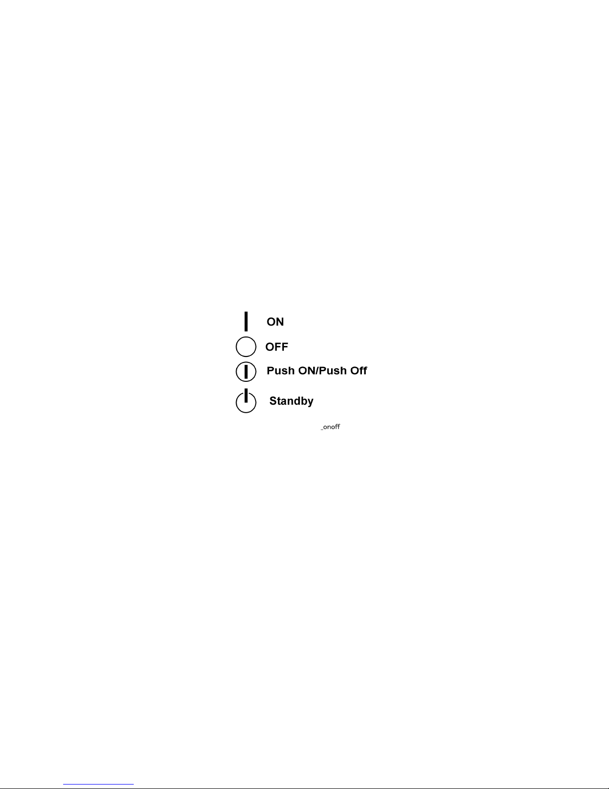
Switches and Symbols
Where symbols are used on or near switches on machines for Europe and other areas, the
meaning of each symbol conforms with IEC60417.
Responsibilities of the Customer Engineer
Maintenance
Maintenance shall be done only by trained customer engineers who have completed service
training for the machine and all optional devices designed for use with the machine.
Installation
The main machine and options can be installed by either the customer or customer engineer.
The customer or customer engineer must follow the installation instructions described in the
operating instructions.
CÓPIA NÃO CONTROLADA
CÓPIA NÃO CONTROLADA

Reference Material for Maintenance
Maintenance shall be done with the special tools and the procedures prescribed for
maintenance of the machine described in the reference materials (service manuals,
technical bulletins, operating instructions, and safety guidelines for customer engineers).
Use only consumable supplies and replacement parts designed for use with the
relevant machine.
Before Installation, Maintenance
Shipping and Moving the Machine
Work carefully when lifting or moving the machine. If the machine is heavy, two or
more customer engineers may be required to prevent injuries (muscle strains,
spinal injuries, etc.) or damage to the machine if it is dropped or tipped over.
Personnel moving or working around the machine should always wear proper
clothing and footwear. Never wear loose fitting clothing or accessories (neckties,
loose sweaters, bracelets, etc.) or casual footwear (slippers, sandals, etc.) when
lifting or moving the machine.
Always unplug the power cord from the power source before you move the machine.
Before you move the machine, arrange the power cord so it will not fall under the
machine.
Power
Always turn the machine off and disconnect the power plug before doing any
maintenance procedure. After turning the machine off, power is still supplied to the
main machine and other devices. To prevent electrical shock, switch the machine
off, wait for a few seconds, and then unplug the machine from the power source.
Before you do any checks or adjustments after turning the machine off, work
carefully to avoid injury. After removing covers or opening the machine to do checks
or adjustments, avoid touching electrical components or moving parts (gears, timing
belts, etc.).
After turning the machine on with any cover removed, keep your hands away from
electrical components and moving parts. Never touch the cover of the fusing unit,
gears, timing belts, etc.
CÓPIA NÃO CONTROLADA
CÓPIA NÃO CONTROLADA

Installation, Disassembly, and Adjustments
After installation, maintenance, or adjustment, always check the operation of the
machine to make sure that it is operating normally. This ensures that all shipping
materials, protective materials, wires and tags, metal brackets, etc., (attached to
protect the machine during shipping), have been removed and that no tools remain
inside the machine.
Never use your fingers to check moving parts that are causing spurious noise.
Never use your fingers to lubricate moving parts while the machine is operating.
Special Tools
Use only standard tools approved for machine maintenance.
For special adjustments, use only the special tools and lubricants described in the
service manual. Using tools incorrectly, or using tools that could damage parts,
could damage the machine or cause injuries.
During Maintenance
General
Before you begin a maintenance procedure always switch the machine off.
Disconnect the power plug from the power source.
Allow the machine to cool for at least 10 minutes.
Avoid touching the components inside the machine that are labeled as hot surfaces.
CÓPIA NÃO CONTROLADA
CÓPIA NÃO CONTROLADA

Safety Devices
Never remove any safety device (a fuse, thermistor, etc.) unless it requires
replacement. Always replace a safety device immediately.
Never do any procedure that defeats the function of any safety device. Modification
or removal of a safety device (fuse, thermistor, etc.) could cause a fire and personal
injury. After removal and replacement of any safety device, always test the
operation of the machine to ensure that it is operating normally and safely.
For replacement parts use only the correct fuses, thermistors, circuit breakers, etc.
rated for use with the machine. Using replacement devices not designed for use
with the machine could cause a fire and personal injuries.
Organic Cleaners
During preventive maintenance, never use any organic cleaners (alcohol, etc.)
other than those described in the service manual. (Refer the “2. Preventive
Maintenance” in the Service Manual.)
Make sure the room is well ventilated before using any organic cleaner. Always use
organic solvents in small amounts to avoid breathing the fumes and becoming
nauseous.
Switch the machine off, unplug it, and allow it to cool before doing preventive
maintenance. To avoid fire or explosion, never use an organic cleaner near any
component that generates heat.
Wash your hands thoroughly after cleaning parts with an organic cleaner to avoid
contamination of food, drinks, etc. which could cause illness.
Power Plug and Power Cord
Before servicing the machine (especially when responding to a service call), always
make sure that the power plug has been inserted completely into the power source.
A partially inserted plug could lead to heat generation (due to a power surge caused
by high resistance) and cause a fire or other problems.
Always check the power plug and make sure that it is free of dust and lint. Clean it if
necessary. A dirty plug can generate heat and cause a fire.
Inspect the entire length of the power cord for cuts or other damage. Replace the
power cord if necessary. A frayed or otherwise damaged power cord can cause a
CÓPIA NÃO CONTROLADA
CÓPIA NÃO CONTROLADA

short circuit which could lead to a fire or personal injury from electrical shock.
Check the length of the power cord between the machine and power supply. Make
sure the power cord is not coiled or wrapped around any object such as a table leg.
Coiling the power cord can cause excessive heat to build up and could cause a fire.
Make sure that the area around the power source is free of obstacles so the power
cord can be removed quickly in case of an emergency.
Make sure that the power cord is grounded (earthed) at the power source with the
ground wire on the plug.
Connect the power cord directly into the power source. Never use an extension
cord.
When you disconnect the power plug from the power source, always pull the plug,
not the cable.
After Installation Servicing
Disposal of Used Items
Ink is flammable. Never attempt to incinerate empty ink cartridges.
Always dispose of used items in accordance with the local laws and regulations
regarding the disposal of such items.
To protect the environment, never dispose of this product or any kind of waste from
consumables at a household waste collection point. Dispose of these items at one
of our dealers or at an authorized collection site.
Points to Confirm with Operators
At the end of installation or a service call, instruct the user about use of the machine.
Emphasize the following points.
Show operators how to remove jammed paper and troubleshoot other minor problems
by following the procedures described in the operating instructions.
Point out the parts inside the machine that they should never touch or attempt to
remove.
Confirm that operators know how to store and dispose of consumables such as ink
cartridges, ammonia water, paper, etc.
Make sure that all operators have access to an operating instruction manual for the
machine.
Confirm that operators have read and understand all the safety instructions described in
CÓPIA NÃO CONTROLADA
CÓPIA NÃO CONTROLADA

the operating instructions.
Demonstrate how to turn off the power and disconnect the power plug (by pulling the
plug, not the cord) if any of the following events occur:
1. Something has spilled into the product.
2. Service or repair of the product is necessary.
3. The product cover has been damaged.
Caution operators about removing paper fasteners around the machine. They should
never allow paper clips, staples, or any other small metallic objects to fall into the
product.
Make sure the operators understand the following points:
The operator must lift the output tray to release the paper cassette before
loading paper.
Paper is loaded in the standard paper cassette without removing it from the
machine.
The operator should never attempt to remove the paper cassette from the
machine.
Special Safety Instructions For Ink Cartridges
Accidental Exposure To Ink
If ink gets on the skin, wash the affected area immediately with soap and cold
running water.
If ink gets into the eyes, immediately flush the eyes with cold running water. If there
are signs of irritation or other problems, seek medical attention.
If ink is swallowed, drink a strong solution of cold water and table salt to induce
vomiting. Seek medical attention immediately.
Ink is difficult to remove from fabric. Work carefully to avoid staining clothing when
performing routine maintenance or replacing cartridges.
CÓPIA NÃO CONTROLADA
CÓPIA NÃO CONTROLADA
 Loading...