

Page 1

ISDN
Protocol Handbook
Revised on September 20th, 1995
Page 2

I. Layer 1
Page 3
g
g
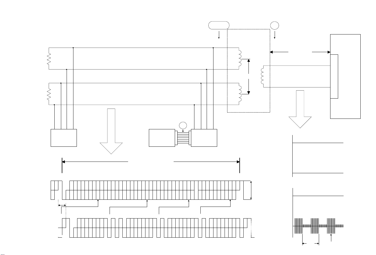
Note: Phantom power (40V). Ping-pong transmission may be
g
g
different, depending on the network company.
LAYER 1 CONFIGURATION DIAGRAM
Ω
100
100
Ω
→ → → → → → → → → →
→ → → → → → → → → →
S/T
TA
TB
RA
DSU
-
40V
U
7 km max.
L1
→ → → → → →
-pong transmission
Pin
or echo cancellin
L2
NTT
D70
I
S
→ → → → → →
N
+
RB
I - 1
R
[Durin
standby]
+55V
(L1)
0V
(L2)
communication]
[Durin
0V
(L2)
U→NU
UN
→
→
NU
NN
U
→
→
DSU→TE
0(+)
1
0(-)
→
DSU
TE
TE1 T A
Existing
terminal TE2
V/X series
48bit (250µs, 192kbps)
DL. B1B1B1B1B1B1B1B1 E D A FAN B2B2B2B2B2B2B2B2 E D M B1B1B1B1B1B1B1B1 E D S B2B2B2B2B2B2B2B2 E D L. F L.FL.
2-bit offset
D B1B1B1 B1B1 B1B1 B1 L. D L. FA L. B2 B2B2 B2B2B2 B2B2 L. D L. B1B1 B1B1 B1B1 B1B1 L. D L. B2B2 B2B2 B2B2 B2B2 L. D L. F L.FL.L.
1.5V p-p
-30V
(L1)
2.5ms
320kbps
Page 4
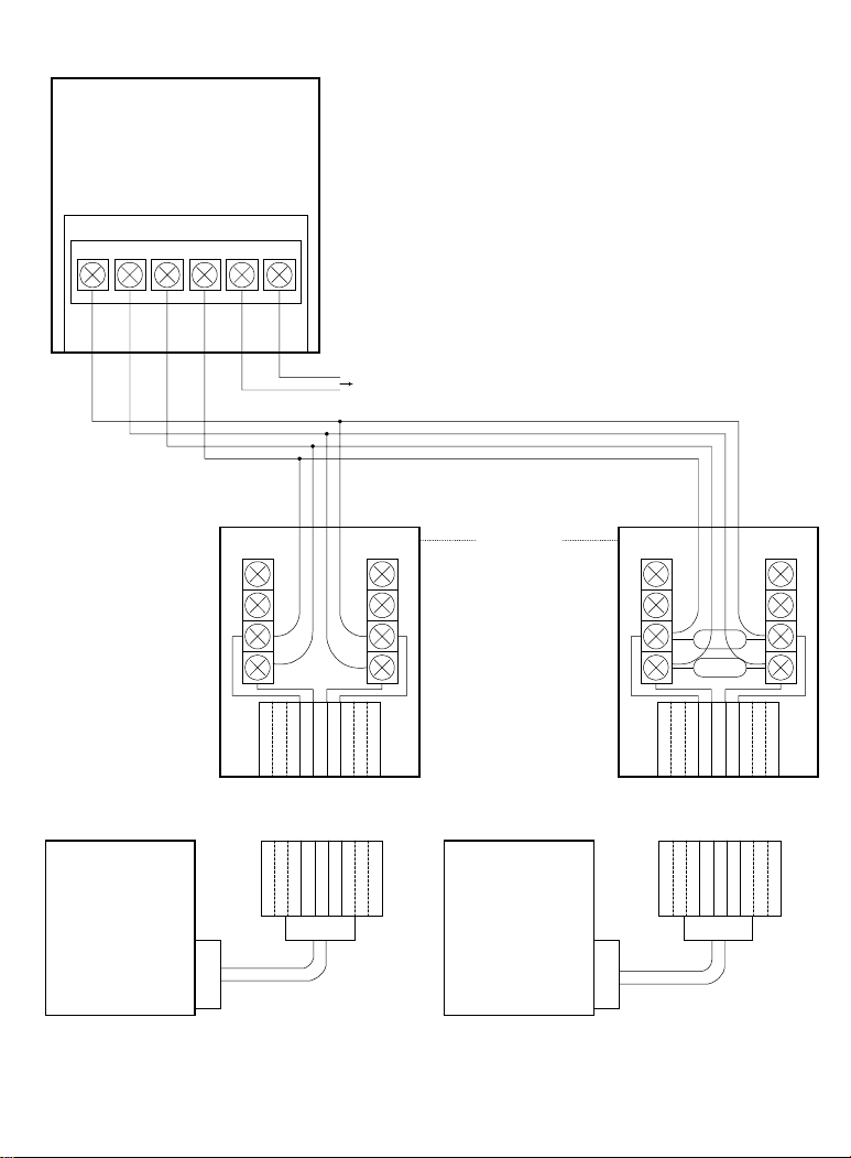
D S U
(
)
DSU CONNECTION
JAPAN
TA RA RB
MJ - 8S MJ - 8SR
TB
L1 L2
TB
RB
87654321
87654321
8P
To subscriber line
TA
RA
Bus wiring
TA
RA
RB
TB
87654321
87654321
8P
100
100
Ω
Ω
ISDN terminal
TE1
8P
I - 2
TE1
ISDN terminal
8P
Page 5

Example of pseudo-ternary signalling (AMI Code)
000 00011111111
+0
1
-0
Time
I - 3
Page 6

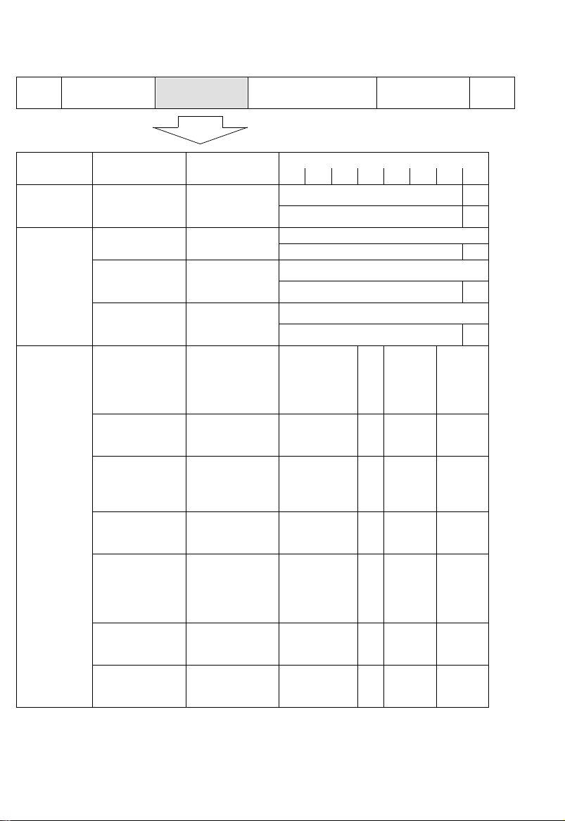
Layer 1 Status
The ITU-T I.430 recommendation (the basic user-network inter face - Layer 1 specification) specifies layer 1 activation/deactivation procedures.
Before understanding the procedures, the status and INFO signals should be noted.
TE (Terminal Equipment) Status
Status Description
F1 TE is turned off.
F2 TE is turned on, but no signal is exchanged.
F3 TE is stopped. No signal is exchanged between TE and NT.
F4 TE is waiting for the response to the INFO1 signal from NT.
F5 TE is checking if the signal from the NT is INFO2 or INFO4.
F6 TE is waiting for signals from NT after receiving the INFO2 signal.
F7 TE and NT are synchronized.
F8 TE has failed to synchronize with NT, and is waiting for the stop request from NT
NT (Network Termination) Status
Status Description
G1 NT has stopped.
G2 NT is sending INFO2.
G3 TE and NT are synchronized.
G4 NT is terminating itself.
INFO Signals
NT to TE Direction TE to NT Direction
INFO0 No signal INFO0 No signal
INFO2
INFO4 Synchronized frame INFO3 Synchronized frame
Activation signal in
synchronized condition
INFO1
Activation signal in nonsynchronized condition
Page 7
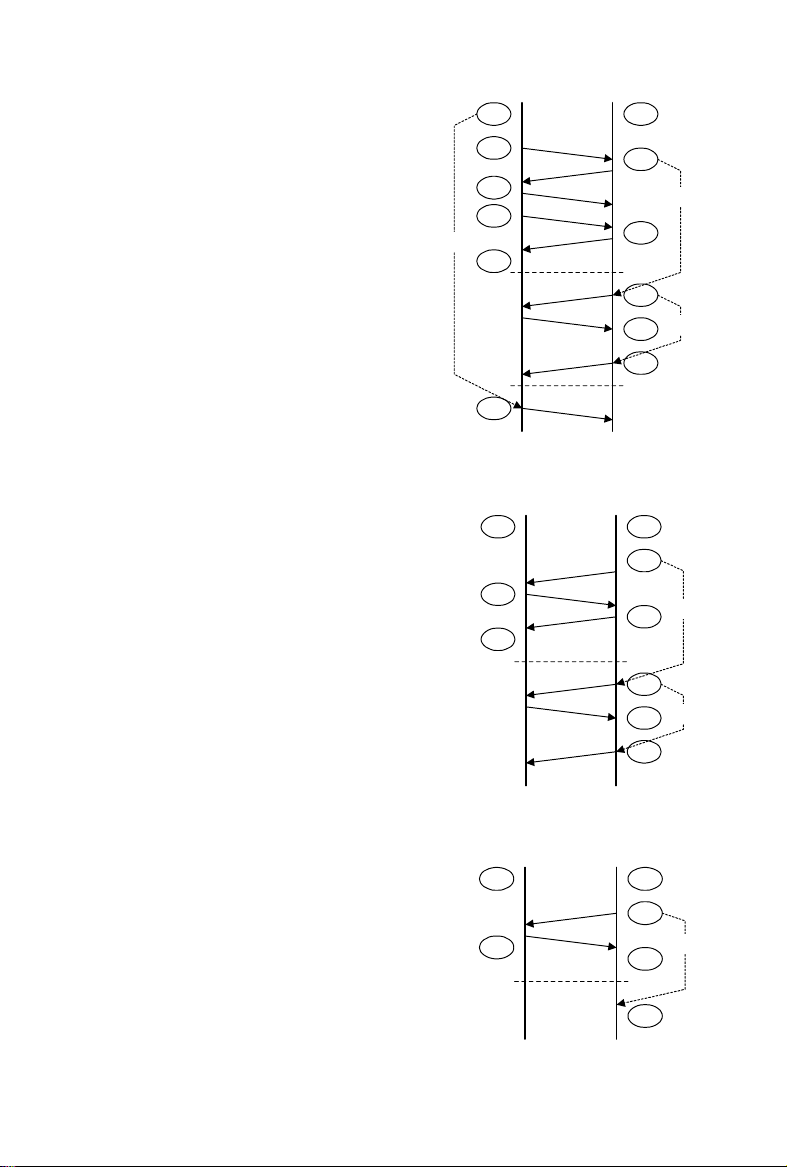
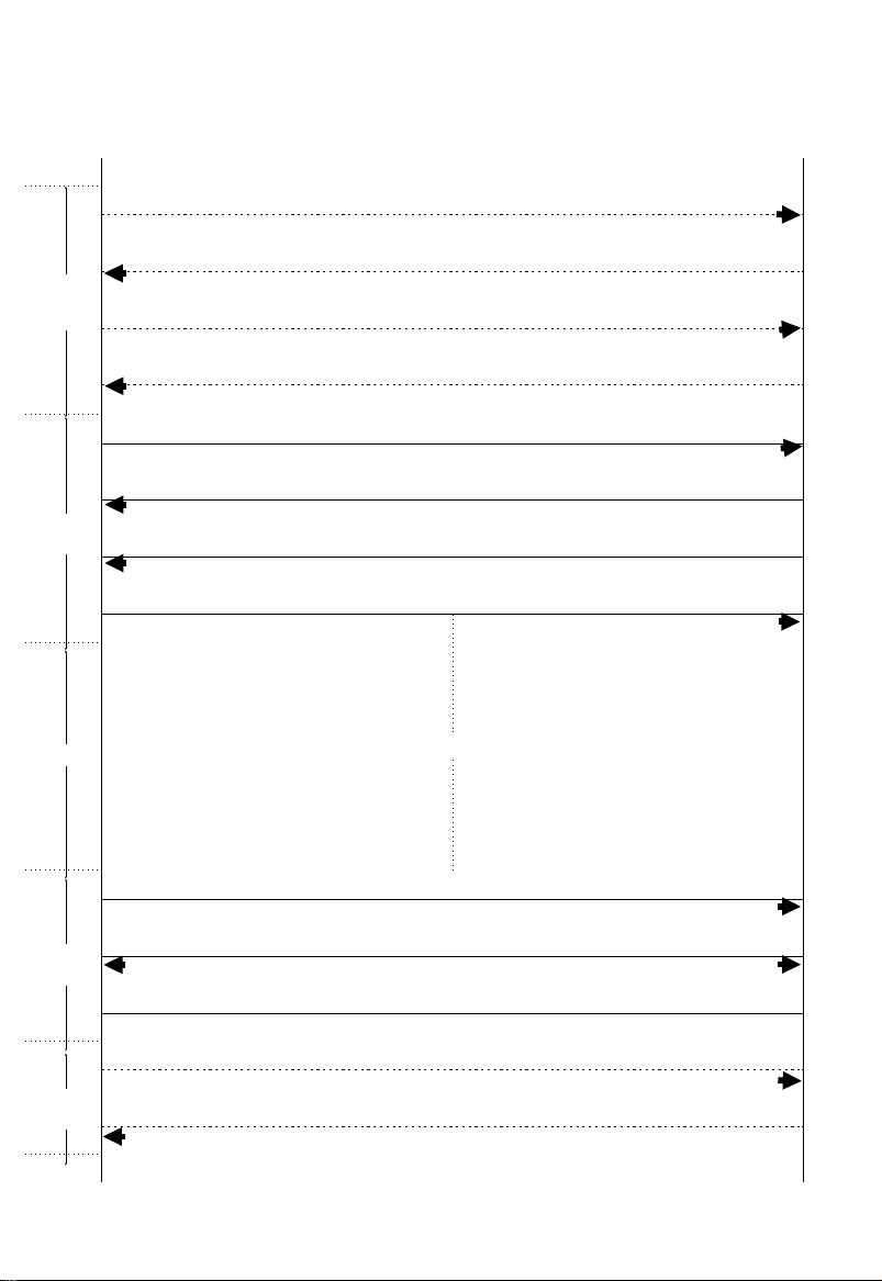
Activation Procedure from the TE
In idle “F3” status , the TE sends the INFO1
signal to the NT and changes to “F4” status.
The NT then changes to “G2” status and
sends the INFO2 signal to the TE.
The TE changes to “F5” status and stops
sending signals to synchronize itself to the
signal from the NT.
After the TE has synchronized to the signal,
it sends the INF O3 signal to the NT and
changes to the “F6” status.
The NT then changes to “G3” status and
sends the INFO4 si gnal back to the TE to inform that a physic al lin k ha s be en est ablished.
The timers T1, T2 and T3 are used to reset
the TE or NT if a correct response has not
been received before the timers expire.
T3
F3
F4
F5
F6
F7
F3
TE
INFO1
INFO2
INFO0
INFO3
INFO4
INFO0
INFO0
INFO0
INFO0
NT
G1
G2
G3
G4
G1
G1
h143x510.wmf
T1
T2
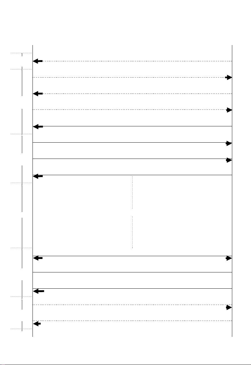
Activation Procedure from the NT
The procedure starts from the NT by sending the INFO2 signal to the TE.
After the TE has synchronized to the signal,
it sends the INF O3 signal to the NT and
changes to the “F6” status.
The NT then changes to “G3” status and
sends the INFO4 si gnal back to the TE to inform that a physic al lin k ha s be en est ablished.
The timers T1 and T2 are used to reset the
NT if a correct response ha s no t be en received before the ti me rs ex pi re.
Termination Procedure from the NT
The terminatio n pro ce du r e st art s fro m sy nchronized status (“F7” status for the TE and
“G3” status for the NT).
To terminate the physical connection, the NT
just stops sending signals and ch an ge s to
“G1” status. (The INFO0 signal means no signal is sent from the NT.) Then, the TE also
stops sending signals and changes to “F3”
status.
INFO2
INFO3
INFO4
INFO0
INFO0
INFO0
NT
G1
G2
G3
G4
G1
G1
TE
F3
F6
F7
h143x511.wmf
INFO0
INFO0
NT
G4
G1
G1
TE
F7 G3
F3
T1
T2
T2
h143x512.wmf
I - 5
Page 8

II. D Channel, Layer 2
Page 9
g
g
L
A
Y
E
R
1
100
100
Configuration of Dch layers 1 to 3
Ω
Ω
TE1 T A
→ → → → → → → → → →
DSU
TA
-
TB
RA
40V
→ → → → → → → → → →
+
RB
L1
→ → → → → →
-pong transmission
Pin
or echo cancellin
L2
NTT
D70
I
S
→ → → → → →
N
L
A
Y
E
R
2
L
A
Y
E
R
3
DL. B1 B1 B1 B1 B1 B1 B1 B1 E D A FA N B2 B2 B2 B2 B2 B2 B2 B2 E D M B1 B1 B1 B1 B1 B1 B1 B1 E D S B2 B2 B2 B2 B2 B2 B2 B2 E DFL.
0(+)
1
0(-)
FLAG A C I FCS FLAG
0111111 0000000000 000000 0000000000 000000 0000000000 000000 00000000000000000 00000000000000 00 000000000000000000000000000000 0000000000000000000000000000000 000000000000 000 00 1111110···
Protocol ID
00010000
Call ref length
10000000
Call referance
XXXXXXXX
Mesage type Info element length
XXXXXXXX XXXXXXXX XXXXXXXX XXXXXXX XXXXXXX
Information element D
Info element contents
···
XX
··
··
··
Page 10

D channel, layer 2-1 (Q.921:I.441:LAPD)
F
1 oct
A
2 oct
87654321
C
1 or 2 oct
I
N oct
SAPI
(Note 3)
TEI
(Note 4)
Note 1. Meaning of the EA bit (Address field extension bit)
EA value Meaning
0 Address field extension
1 Address field end
Note 2. Meaning of the C/R bit (Command/Response field bit)
C/R value Definition
→
N command
0
1
U
→
U response
N
→
U command
N
→
N response
U
C/R
(Note 2)
C
R
R
C
FCS
2 oct
EA
(Note 1)
EA
(Note 1)
NetUser
NetUser
F
1 oct
0
1
Note 3. SAPI value assignment (Service Access Point Identifier)
SAPI value Related entity
0 Call control procedure
1
16 Packet communication procedure (X.25 level 3)
63 Layer 2 management procedure
Other Reserved for future use
Reserved for packet communication using Q.931 call control
procedure
Note 4. TEI value assignment (Terminal endpoint Idenifier)
TEI value User terminal type
0 ~63 Non-automatic TEI setting user terminal
64~126 Automatic TEI setting user terminal
127 B roadcasting format data link connection TEI
II - 2
Page 11
D channel, layer 2-2 (Q.921:I.441:LAPD)
F
1 oct
Format Command Response
Information
transfer
(I)
Supervisory
Unnumbered
A
2 oct
(I)
(Information)
RR
(Receive ready)RR(Receive ready)
RNR
(Receive not
ready)
REJ
(Re-transfer
request)
SABME
(Set
asynchronous
balanced mode
extended)
UI
(Unnumbered
system
information)
DISC
(Disconnect)
C
1 or 2 oct
(Receive not
(Re-transfer
request)
(Disconnect
(Unnumbered
system
acknowledgement)
RNR
ready)
REJ
DM
mode)
UA
I
N oct
Coding
87654321oct
N (S) 0 1
N (R) P 2
000000011
N (R) P/F 2
000001011
N (R) P/F 2
000010011
N (R) P/F 2
011P11111
000F11111
000P00111
010P00111
011F00111
FCS
2 oct
F
1 oct
FRMR
(Frame reject)
XID
(ID exchange)
: P/F When sent as a command: (P) bit
∗
XID
(ID exchange)
When sent as a response: (F) bit
: Provision of XID is not yet scheduled.
∗
II - 3
100F01111
101P/F11111
Page 12

TEI management procedure
•
The TEI management procedure includes the following procedures:
. TEI assignment procedure
. TEI check procedure
. TEI clear procedure
. TEI identifying procedure executed by the user as an option
Conceptually, these procedures belong to the layer management entity.
The network side layer management entity is referred to as Assignment Source Point
(ASP). The TEI management procedure is performed by using the data link layer of a
non-confirming type information transfer.
SAPI is set to 63, and TEI is set to 127.
The following shows the format of the me ss ag es tr an sf erre d between layer management entities:
oct87654321
1 Management entity indentifier - mei: 15 (0FH)
2 Reference number (Ri)
3 Reference number (Ri)
4 Message type - XXH
5 Operation indication Ai value E=1: End oct
Ri: A value in a range of 0 to 65535
randomly generated by user equipment
Message
name
ID request
→
(User
Net)
ID assignment
(User → Net)
ID reject
→
(Net
User)
ID check re-
quest
→
(Net
User)
ID check re-
sponse
→
Net)
(User
ID clear
→
User)
(Net
ID check
→
Net)
(User
Management
entity
identifier
00001111 0 ~ 65535 00000001 Ai=127: Any TEI is ready
00001111 0 ~ 65535 00000010
00001111 0 ~ 65535 00000011
00001111
00001111 0 ~ 65535 00000101 Ai=0 to 126: TEI value being used
00001111
00001111
Reference
number
Not used
(Code 0)
Not used
(Code 0)
Not used
(Code 0)
Message
type
Ai=64 to 126: TEI is the assigned
value
Ai=64 to 126: Request abnormal
(Reject TEI)
Ai=127: TEI assignment is not possible
00000100
00000110
00000111 Ai=0 to 126: TEI value to check
Ai=127: Check all TEI values
Ai=0 to 126: TEI value to check
Ai=127: Request to clear all TEI values
Ai=0 to 126: TEI value to clear
Operation indication
Ai
II - 4
Page 13
TEI assignment procedure (call from user)
•
User
UI
SAPI:63, TEI: 127, mei: 15, Ri: XXXXH, Message type 01 (H), Ai: 127
UI
SAPI:63, TEI: 127, mei: 15, Ri: XXXXH, Message type 02 (H), Ai: YYY
D ch
layer 2
SABME
SAPI: 0, TEI: YYY
UA
SAPI:0 , TEI:YYY
D ch
layer 3
B ch
D ch
layer 3
D ch
layer 2
I
SAPI: 0, TEI: YYY [
I
SAPI: 0, TEI: YYY [
I
SAPI: 0, TEI: YYY [
I
SAPI: 0, TEI: YYY [
Procedure on
I
SAPI: 0, TEI: YYY [
I
SAPI: 0, TEI: YYY [
I
SAPI: 0, TEI: YYY [
DISC
SAPI: 0, TEI: YYY
UA
SAPI: 0, TEI: YYY
SETUP
]
CALL PROC
CONN
]
CONN ACK
B ch
DISC
]
REL
]
REL COMP
]
]
]
II - 5
Page 14
TEI assignment procedure (call from network)
•
User
D ch
layer 3
D ch
layer 2
D ch
layer 3
B ch
UI
SAPI: 0, TEI: 127 [
UI
SAPI:63, TEI: 127, mei: 15, Ri: XXXXH, Message type 01 (H), Ai: 127
UI
SAPI:63, TEI: 127, mei: 15, Ri: XXXXH, Message type 02 (H), Ai: YYY
SABME
I
SAPI: 0, TEI: YYY [
I
SAPI: 0, TEI: YYY [
I
SAPI: 0, TEI: YYY [
SAPI: 0, TEI: YYY
UA
SAPI: 0, TEI:YYY
Procedure on
SETUP
]
CALL PROC
CONN
]
CONN ACK
B ch
]
]
D ch
layer 3
D ch
layer 2
I
SAPI: 0, TEI: YYY [
I
SAPI: 0, TEI: YYY [
I
SAPI: 0, TEI: YYY [
DISC
SAPI: 0, TEI: YYY
UA
SAPI: 0, TEI: YYY
II - 6
DISC
]
REL
]
REL COMP
]
Page 15

III. D Channel, Layer 3
Page 16
D channel, layer 3-1 (Q.931: I.451)
F
1 oct
Protocol
discriminator
08H
↓
Table 1
A
2 oct
C
1 or 2 oct
Call reference
1H XXH
↓
Table 2
Message type
XXH
I
N oct
Differs depending on message type
FCS
2 oct
0~N oct
Table 1. Protocol Discriminator
87654321
00000000User’s typical protocol identifier
00000001OSI high layer protocol
00000010Recommendation X.244
00000011Reserved for system management converse function
00000100A5 characters
00000111Standard JT-V.120 speed compatibility
0 0 0 0 1 0 0 0 Standard JT-Q.931 user/network setting message
00010000Reserved for other network layer or layer 3 protocol
|
00111111
01000000National use
01000001
01000010
|
01001111
01010000
|
11111110
Other than above Reserved
including standard JT-X.25
Recommendation X.208/X.209 (ASN.1: Abstract syntax
descriptive method 1)
National use
Reserved for other network layer or layer 3 protocol
including standard JT-X.25
F
1 oct
Table 2. Call Reference
87654321
Reserved Call reference length
0 0 0 0 0 0 0 1
F X X X X X X X
III - 1
F=0: Calling side
F=1: Called side
Page 17

F
1 oct
A
2 oct
D channel, layer 3-2 (Q.931:I.451)
C
1 or 2 oct
I
N oct
FCS
2 oct
F
1 oct
Protocol
discriminator
08H
Call reference
01H XXH
Table 3. Message Type
Message type
XXH
↓
Table 3
Differs depending on message type
0~N oct
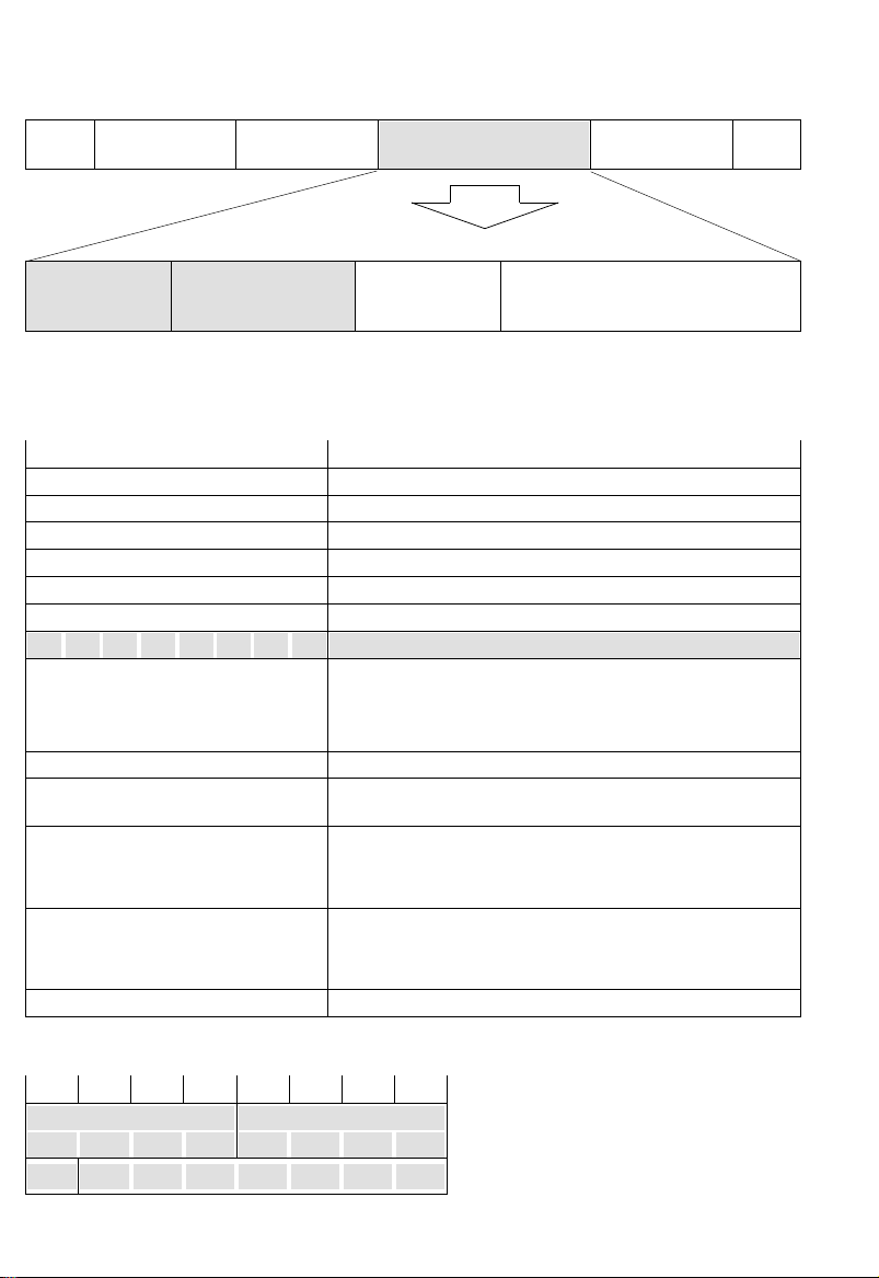
87654321 HEX Name Full name Function
0000001 01 ALERT ALERTING
0000010 02 CALL PROC CALL PROCEEDING
0000011 03 PROG PROGRESS Indicates call progress
0000101 05 SETUP SETUP Call set-up request
0000111 07 CONN CONNECT
0001101 0D SETUP ACK SETUP ACKNOWLEDGE
0001111 0F CONN ACK
0100000 20 USER INFO USER INFORMATION User to user signal
0100001 21 SUSP REJ SUSPEND REJECT
0100010 22 RES REJ RESUME REJECT
0100101 25 SUSP SUSPEND
0100110 26 RES RESUME
0101101 2D SUSP ACK
0
0101110 2E RES ACK
1000101 45 DISC DISCONNECT Call clear request
1000110 46 REST RESTART Initial setting request
1001101 4D REL RELEASE
1001110 4E REST ACK
1011010 5A REL COMP RELEASE COMPLETE
1100010 62 FAC FACILITY
1101110 6E NOTIFY NOTIFY
1110101 75 STAT ENQ STATUS ENQUIRY Party status inquiry
1111001 79 CONG CON
1111011 7B INFO INFORMATION
1111101 7D STAT STATUS
SETUP ACK, USER INFO, REST, REST ACK, FAC, and CONG CON not provided by NTT (as
Note:
of July 1989)
CONNECT ACKNOWLEDGE
SUSPEND ACKNOWLEDGE
RESUME ACKNOWLEDGE
RESTART ACKNOWLEDGE
CONGESTION CONTROL
III - 2
Informs that receiving side
user is being called
Informs that ca l l s et -u p
procedure is bei ng execu ted
Called side response
notification
Acknowledgement of
SETUP
Acknowledgement of
CONN
Informs that temporary
interruption is rejected
Informs that interrupted call
cannot be resumed
Call temporary interrupt
request
Interrupted call resume
request
Temporary interruption
complete notification
Interrupted call resume
complete notification
Channel clear complete
notification and call number
clear request
Initial setting complete
notification
Channel clear and call
number clear complete
notification
Additional service request
and check
Notification of call
information
Additional call control, and
other information
User/network status
notification
Informs the status of the
user and the network.
Type
Call
setting
During
comm-
uni-
cation
Call
clear
Others
Page 18

F
1 oct
A
2 oct
D channel, layer 3-3 (Q.931:I.451)
C
1 or 2 oct
I
N oct
FCS
2 oct
F
1 oct
Protocol discriminator
08H
Call reference
01H XXH
Table 4. Information Elements
1. SETUP (05)
Information element HEX Type Contents
Protocol discriminator 08
Call reference 01XX
Message type 05
Bearer capability 04
Channel identifier 18 Optional
Facilities 1C Optional
Progress identifier 1E Optional
Display 28 Optional
Keypad 2C Optional
Signal 34 Optional
Feature activation 38 Optional
Feature indication 39 Optional
Calling party address 6C Optional
Calling party subaddress 6D Optional
Called party address 70 Optional
Called party su badd ress 71 Optional
Transit network selection 78 Optional
Low layer compatibility
High layer compatibility 7D Optional
User to user 7E Optional
Mandatory
Mandatory
Mandatory
Mandatory
7C Optional
Table 1
Table 2
Table 5
Table 6
Table 7
Table 8
Table 9
Table 10
Table 12
Table 13
Table 14
Table 15
Table 16
Table 17
Table 18
Table 19
Table 20
Table 21
3. ALERT (01)
Information element HEX Type Contents
Protocol discriminator 08
Call reference 01XX
Message type 01
Channel identifier 18 Optional
Facilities 1C Optional
Progress identifier 1E Optional
Display 28 Optional
Signal 34 Optional
Feature activation 38 Optional
Feature indication 39 Optional
User to user 7E Optional
Mandatory
Mandatory
Mandatory
Table 1
Table 2
Table 3
Table 6
Table 7
Table 8
Table 9
Table 12
Table 13
Table 21
Message type
XXH
Differs depending on message type
0~N oct
↓
Table 4: 1 to 25
2. CALL PROC (02)
Information element HEX Type Contents
Protocol discriminator 08
Call reference 01XX
Message type 02
Channel identifier 18 Optional
Progress identifier 1E Optional
Display 28 Optional
Feature indication 39 Optional
Mandatory
Mandatory
Mandatory
4. PROG (03)
Information element HEX Type Contents
Protocol discriminator 08
Call reference 01XX
Message type 03
Cause 08 Optional
Progress identifier 1E Optional
Indication 28 Optional
User to user 7E Optional
Mandatory
Mandatory
Mandatory
5. CONN (07)
Information element HEX Type Contents
Protocol discriminator 08
Call reference 01XX
Message type 07
Channel identifier 18 Optional
Facilities 1C Optional
Progress identifier 1E Optional
Display 28 Optional
Signal 34 Optional
Feature activation 38 Optional
Feature indication 39 Optional
Low layer compat ibil ity
User to user 7E Optional
Mandatory
Mandatory
Mandatory
7C Optional
Table 1
Table 2
Table 3
Table 6
Table 8
Table 9
Table 13
Table 1
Table 2
Table 3
Table 22
Table 8
Table 9
Table 21
Table 1
Table 2
Table 3
Table 6
Table 7
Table 8
Table 9
Table 12
Table 13
Table 19
Table 21
III - 3
Page 19

6. SETUP ACK (0D)
Information element HEX Type Contents
Protocol discriminator 08
Call reference 01XX
Message type 0D
Channel identifier 18 Optional Table 6
Progress identifier 1E Optional Table 8
Mandatory
Mandatory
Mandatory
Table 1
Table 2
Table 3
7. CONN ACK (0F)
Information element HEX Type Contents
Protocol discriminator 08
Call reference 01XX
Message type 0F
Channel identifier 18 Optional Table 6
Display 28 Optional Table 9
Signal 34 Optional
Mandatory
Mandatory
Mandatory
Table 1
Table 2
Table 3
8. USER INFO (20)
Information element HEX Type Contents
Protocol discriminator 08
Call reference 01XX
Message type 21
More data 08 Optional Table 23
User to user 28 Optional Table 21
Mandatory
Mandatory
Mandatory
Table 1
Table 2
Table 3
9. SUSP REJ (21)
Information element HEX Type Contents
Protocol discriminator 08
Call reference 01XX
Message type 21
Cause indication 08 Optional Table 22
Display 28 Optional Table 9
Mandatory
Mandatory
Mandatory
Table 1
Table 2
Table 3
10. RES REJ (22)
Information element HEX Type Contents
Protocol discriminator 08
Call reference 01XX
Message type 22
Cause 08 Optional Table 22
Display 28 Optional Table 9
Fixed shift procedure 96 Optional Table 24
Charge notification 01 Optional Table 25
Mandatory
Mandatory
Mandatory
Table 1
Table 2
Table 3
11. SUSP (25)
Information element HEX Type Contents
Protocol discriminator 08
Call reference 01XX
Message type 25
Call identification 20 Optional Table 26
Mandatory
Mandatory
Mandatory
12. RES (26)
Information element HEX Type Contents
Protocol discriminator 08
Call reference 01XX
Message type 26
Call identification 20 Optional Table 26
Mandatory
Mandatory
Mandatory
13. SUSP ACK (2D)
Information element HEX Type Contents
Protocol discriminator 08
Call reference 01XX
Message type 2D
Display 28 Optional Table 9
Mandatory
Mandatory
Mandatory
14. RES ACK (2E)
Information element HEX Type Contents
Protocol discriminator 08
Call reference 01XX
Message type 2E
Channel identifier 18 Optional Table 6
Display 28 Optional Table 9
Mandatory
Mandatory
Mandatory
15. DISC (45)
Information element HEX Type Contents
Protocol discriminator 08
Call reference 01XX
Message type 45
Cause 08 Optional Table 22
Facilities 1C Optional Table 7
Progress identifier 1E Optional Table 8
Display 28 Optional Table 9
Signal 34 Optional Table 11
Feature indication 39 Optional Table 13
User to user 7E Optional Table 21
Fixed shift procedure 96 Optional Table 24
Charge notification 01 Optional Table 25
Mandatory
Mandatory
Mandatory
Table 1
Table 2
Table 3
Table 1
Table 2
Table 3
Table 1
Table 2
Table 3
Table 1
Table 2
Table 3
Table 1
Table 2
Table 3
III - 4
Page 20

16. REST (46)
Information element HEX Type Contents
Protocol discriminator 08
Call reference 01XX
Message type 46
Channel identifier 18 Optional Table 6
Display 28 Optional Table 9
Initial setting indication 79 Optional Table 27
Mandatory
Mandatory
Mandatory
Table 1
Table 2
Table 3
17. REL (4D)
Information element HEX Type Contents
Protocol discriminator 08
Call reference 01XX
Message type 4D
Cause 08 Optional Table 22
Facilities 1C Optional Table 7
Display 28 Optional Table 9
Signal 34 Optional
Feature indication 39 Optional Table 13
User to user 7E Optional Table 21
Fixed shift procedure 96 Optional Table 24
Charge notification 01 Optional Table 25
Mandatory
Mandatory
Mandatory
Table 1
Table 2
Table 3
18. REST ACK (4E)
Information element HEX Type Contents
Protocol discriminator 08
Call reference 01XX
Message type 4E
Channel Identifier 18 Optional Table 6
Display 28 Optional Table 9
Initial setting indication 79
Mandatory
Mandatory
Mandatory
Mandatory
Table 1
Table 2
Table 3
Table 27
20. FAC (62)
Information element HEX Type Contents
Protocol discriminator 08
Call reference 01XX
Message type 62
Facilities 1C
Display Optional Table 9
Mandatory
Mandatory
Mandatory
Mandatory
Table 1
Table 2
Table 3
Table 7
21. NOTIFY (6E)
Information element HEX Type Contents
Protocol discriminator 08
Call reference 01XX
Message type 6E
Transfer capability 04 Optional Table 5
Notification identifier 27
Display 28 Optional Table 9
Mandatory
Mandatory
Mandatory
Mandatory
Table 1
Table 2
Table 3
Table 28
22. STAT ENQ (75)
Information element HEX Type Contents
Protocol discriminator 08
Call reference 01XX
Message type 75
Display 28 Optional Table 9
Mandatory
Mandatory
Mandatory
Table 1
Table 2
Table 3
23. CONG CON (79)
Information element HEX Type Contents
Protocol discriminator 08
Call reference 01XX
Message type 79
Congestion BX
Cause 08 Optional Table 22
Display 28 Optional Table 9
Mandatory
Mandatory
Mandatory
Mandatory
Table 1
Table 2
Table 3
Table 29
19. REL COMP (5A)
Information element HEX Type Contents
Protocol discriminator 08
Call reference 01XX
Message type 5A
Cause 08 Optional Table 22
Facilities 1C Optional Table 7
Display 28 Optional Table 9
Signal 34 Optional
Feature indication 39 Optional Table 13
User to user 7E Optional Table 21
Fixed shift procedure 96 Optional Table 24
Charge notification 01 Optional Table 25
Mandatory
Mandatory
Mandatory
Table 1
Table 2
Table 3
24. INFO (7B)
Information element HEX Type Contents
Protocol discriminator 08
Call reference 01XX
Message type 7B
Cause 08 Optional Table 22
Display 28 Optional Table 9
Keypad 2C Optional Table 10
Signal 34 Optional
Feature activation 38 Optional Table 12
Feature indication 39 Optional Table 13
Mandatory
Mandatory
Mandatory
III - 5
Table 1
Table 2
Table 3
Page 21

25. STAT (7D)
Information element HEX Type Contents
Protocol discriminator 08
Call reference 01XX
Message type 7D
Cause 08
Call status 14
Display 28 Optional Table 9
Mandatory
Mandatory
Mandatory
Mandatory
Mandatory
Table 1
Table 2
Table 3
Table 22
Table 30
III - 6
Page 22

Table 5. Bearer Capability (04)
87654321oct
Information element identifier 1
00000100
L I 2
Coding standard Information transfer capability 3
Extension
00:CCITT standard
01:Other international
10:National standard
1
11:Standard specific
standard
to network
Transfer mode Information transfer rate 4
Extension
1/0
00:Circuit-switched
exchange
10:Packet exchange
Others: Reserved
Structure Configuration Establishment
Extension
1/0
000: Default
001: 8 kHz integrity
100: Service data unit integrity
111: Reserved
Others: Reserved
Mode Information transfer rate (destination to origin)
Extension
00:Bidirectional
symmetric
Others: Reserved
1
Layer 1 identifier User information layer 1 protocol
Extension
1/0
Extension
1/0
Synchronous/
asynchronous
0: Synchronous
1: Asynchronous
Inbound
negotiation
0: Negotiation
not possible
1: Negotiation
possible
Layer 2 identifier User information layer 2 protocol
Extension
1
1 0
Layer 3 identifier User information layer 3 protocol
Extension
1
1 0
00000:Voice (speech)
01000:Unrestricted digital information
01001:Reserved
10000:3.1 kHz audio
11000:Reserved
Others: Already reserved
00000:Packet exchange
10010:Reserved
10000:64 kbps
10011:384 kbps
10101:1536 kbps
10111:Reserved
Others: Reserved
00:Point to point
Others: Reserved
00000:Packet exchange
10010:Reserved
10000:64 kbps
10011:384 kbps
10101:1536 kbps
10111:Reserved
Others: Reserved
00001:CCITT speed compatibility (V.110/X.30): Indicates that 5a to
5d exist.
00010:Recommendation G.711
00011:Recommendation G.711 A-law voice
01001:CCITT standard speed compatibility (JT-X.31): HDLC
flag stuffing
µ
-law voice
00:Immediate
connection
Others: Reserved
User speed
0111: 56 kbps Recommendation V.110
Others: Reserved
Unprovided
00010: TTC standard JT-Q.921
00110: TTC standard JT-X.25 link layer
Others: Reserved
00010: TTC standard JT-Q.931
00110: TTC standard JT-X.25 packet layer
Others: Reserved
*: Option
4a*
4b*
5*
5a*
5b*
5d*
6*
7*
|
III - 7
Page 23
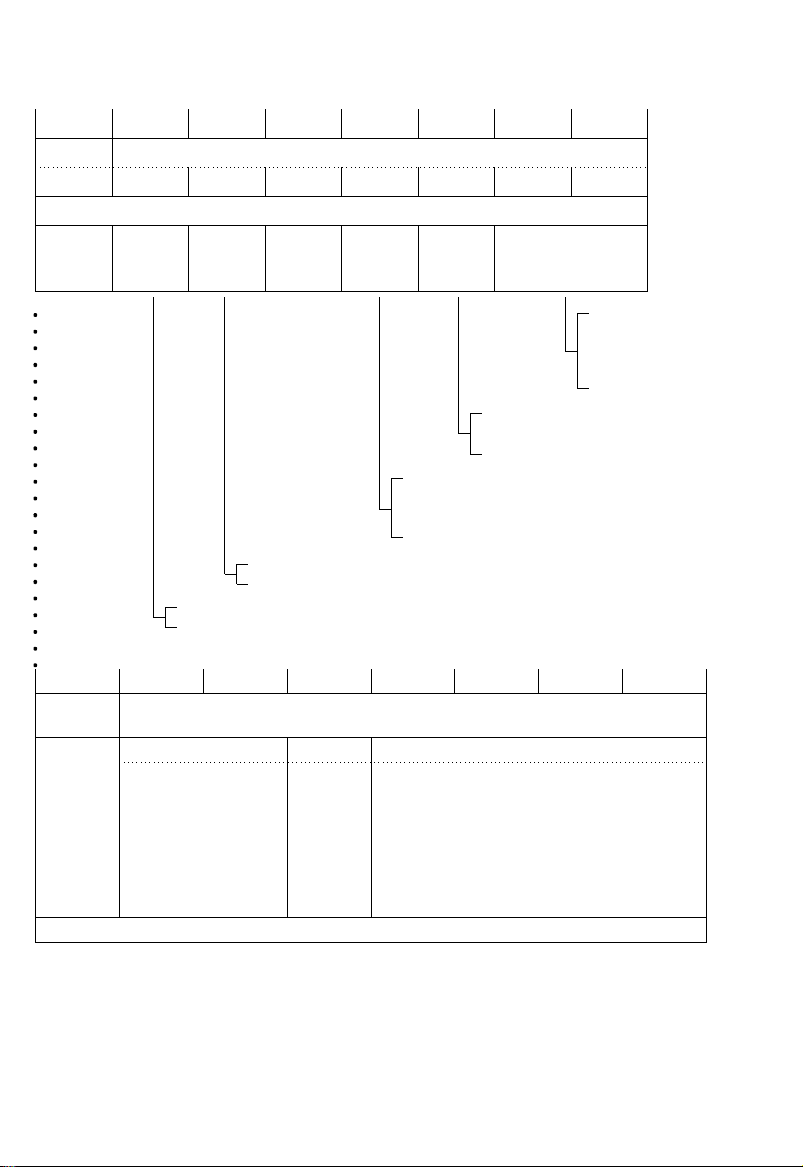
Table 6. Channel Identifier (18)
87654321oct
Information element identifier 1
00011000
L I 2
Exten-
sion
1
Int
id
Int
type
Spare
0
Pre/
Excl
D ch
ind
Information channel
0: Specified channel is not channel D
1: Specified channel is channel D
0: Network can change channel specified by
terminal
1: Network cannot change channel
specified by terminal
0: Basic interface
1: Other interface (primary group interface, etc.)
0: Interface implicitly identified
1: Interface explicitly identified by 1 or more octets from oct 3.1
selection
3
00: No channel
01: B1 channel
10: B2 channel
11: Any channel
87654321
Extension
1
Extension
1
Coding standard
00:CCITT/TTC
standard
01:Reserved for inter-
national standards
other than
CCITT/TTC
standard
10:National standard
11:Standard specific
to network
Interface identifier
Number/map
0: Indicates
to next oct
by number
1: Indicates
to next oct
by slot
Channel type/map element type
0011: Channel B unit
0110: Channel H0 unit
1001: Reserved
Others: Reserved
Channel number/slot map
III - 8
oct
3.1*
3.2*
3.3*
*: Option
Page 24

Table 7. Facilities (1C)
87654321
Information element identifier
00011100
L I
Extension
1
Reserved Service identifier
0 0
10001: Additional service application
Others: Already reserved
Components
Table 8. Progress Identifi er (1E)
87654321
Information element identifier
00011110
L I
Extension
1
Coding standard
00:CCITT standard
01:Other internation-
al standard
10:National standard
11:Standard specific
to generation
source indicated
by bits 3 to 1 of
oct 3
Reserved
0
0000: User
0001: Private network accommodating local
0010: Public network accommodating local users
0011: Relay network
0100: Public network accommodating remote
0100: Private network accommodating remote
0101: International network
0111: Interworking destination network
1010: Reserved
Generation source
users (self side)
(self side)
users (other party side)
users (other party side)
oct
1
2
3
4
.
.
==
.
.
oct
1
2
3
Extension
1
Progress description
0000001:Call is not end-to-end ISDN. Afterwards, progress information
becomes inbound signal.
0000010:Non-ISDN destination
0000011:Non-ISDN originator
0000100:Returning call onto ISDN
0001000:Inbound signal or appropriate pattern can be used
Others: Already reserved
III - 9
4
Page 25

Table 9. Display (28)
87654321
Information element identifier
00101000
L I
Display infor mat io n
(IA5 characters)
MAX 32/80 oct
Table 10. Keypa d Facility (2C)
87654321
Information element identifier
00101100
L I
Keypad facility information
(IA5 characters)
MAX 32 oct
oct
1
2
3
.
.
.
==
.
.
.
oct
1
2
3
.
.
.
==
.
.
.
III - 10
Page 26

Table 11. Signal (34)
87654321
Information element identifier
00110100
L I
00000001
Signal value
00000000: Dial tone
00000001: Calling tone
00000010: Interrupt tone
00000011: Network tone ON
00000100: Busy tone ON
00000101: Check tone ON
00000111: Response tone ON
00001000: Off hook warning tone ON
00111111: Tone OFF
01000000: Calling ON pattern 0
01000001: Calling ON pattern 1
01000010: Calling ON pattern 2
01000011: Calling ON pattern 3
01000100: Calling ON pattern 4
Method of use depends on the network
01000101: Calling ON pattern 5
01000110: Calling ON pattern 6
01000111: Calling ON pattern 7
01001111: Calling OFF
Others: Reserved
Table 12. Featu re Activation (38)
oct
1
2
3
87654321
Information element identifier
00111000
L I
Extension
1/0
Extension
1
Feature identifier number (continued from above)
Feature identifier number
III - 11
oct
1
2
3
3a
Page 27
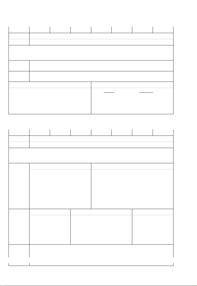
Table 13. Featu re Indication (39)
87654321
Information element identifier
00111001
L I
Extension
1/0
Extension
1
Feature identifier number (continued from above)
Feature identifier number
Reserved Feature status indication
0000: InactiveFeature is in inactive condition
0001: Active Feature is in active condition
0000
0010: Prompt Feature is in prompt condition
0011: Execution Feature is in execution
Other: Already reserved
Status
condition
Meaning
Table 14. Calling Party Address (6C)
87654321
Information element identifier
01101100
L I
Number type Numbering/addressing plan
0000: Undefined
0001: ISDN/phone numbering plan
(recommendation E.164/E.163)
0011: Data numbering plan
(recommendation X.121)
0100: Telex numbering plan
(recommendation F.69)
1000: National numbering plan
1001: Private network numbering plan
1111: Reserved for expansion
Others: Reserved
Network check identifier
00:Reserved
01:User insertion,
000
10:Reserved
11:Network insertion
Number digit
(IA5 characters)
MAX 32 oct
network check
made, successful
Extension
1/0
Extension
1
Reserved
0
000: Undefined
001: International number
010: National number
Number specific to network
011:
100: Local number
110: Short dial number
111: Reserved for expansion
Others: Reserved
Indication identifier Reserved
00:Indication possible
01:Indication not
possible
10:Mutual connection
condition, and no
number can be
displayed
11:Reserved
oct
1
2
3
3a
4
oct
1
2
3
3a
4
.
.
.
===
.
III - 12
Page 28

Table 15. Calling Party Subaddress (6D)
87654321
Information element identifier
01101101
L I
Odd/even
indication
0: Number of
address
signals is
even
1: Number of
address
signals is odd
Reserved
000
Extension
1
Subaddress type
000: NSAP (X.213/ISO 8348 AD2)
010: Subaddress specific to user
Others: Reserved
Format identification (AFI) [Indicates that subaddress is configured in IA5 characters]
01010000
Subaddress information
(IA5 characters)
MAX 19 oct
Table 16. Called Party Address (70)
87654321
Information element identifier
01110000
L I
Type of address Numbering plan identifier
0000: Undefined
0001: ISDN/phone numbering plan
(recommendation E.164/E.163)
0011: Data numbering plan
(recommendation X.121)
0100: Telex numbering plan
(recommendation F.69)
1000: National numbering plan
Extension
1
000: Undefined
001: International number
010: National number
011: Network specific number
100: Local number
110: Short dial number
111: Reserved for expansion
Others: Reserved
1001: Private network numbering plan
1111: Reserved for expansion
Others: Reserved
Reserved
=
=
0
Number digit
(IA5 characters)
MAX 19 oct
.
oct
1
2
3
4
5
.
==
.
.
.
oct
1
2
3
4
.
.
=
.
.
III - 13
Page 29

Table 17. Called Party Subaddress (71)
87654321
Information element identifier
01110001
L I
Odd/even
indication
0: Number of
address
signals is even
1: Number of
address
signals is odd
Reserved
000
Extension
1
Subaddress type
000: NSAP (X.213/ISO 8348
AD2)
010: Subaddress specific to
user
Others: Reserved
Format identifier (AFI) [Indicates that subaddress is configured in IA5 characters]
01010000
Subaddress information
(IA5 characters)
MAX 19 oct
Table 18. Trans it Network Selection (78)
87654321
Information element identifier
01111000
L I
Network identification type Network identification plan
Extension
=
000: User definition
010: National network
011: International network
1
Others: Reserved
=
0000: Undefined
0001: Carrier identification code
0011: Data network identification code
(recommendation X.121)
Others: Reserved
Network identifier
(IA5 characters)
oct
1
2
3
4
5
.
.
==
.
oct
1
2
3
4
.
.
=
.
.
III - 14
Page 30

Table 19. Low Layer Compatibility (7C)
87654321oct
01111100
Coding standard Information transfer capability 3
00:CCITT standard
Extension
Extension
Extension
Extension
Extension
Extension
01:Other international
standard
10:National standard
1/0
11:Standard specific
to network
Negotiation
specification
0: Outbound
negotiation
1
not possible
1: Outbound
negotiation
possible
Transfer mode Information transfer rate 4
00:Circuit-switched
exchange
10:Packet exchange
Others: Already reserved
1/0
000: Default
001: 8 kHz integrity
100: Service data unit integrity
1/0
111: Reserved
Others: Reserved
00:Bi-directional
symmetric
Others: Reserved
1
Layer 1 identifier Layer 1 protocol identifier 5*
1/0
01
000000
Structure Configuration Establishment 4a
Mode Information transfer rate (destination to origin) 4b
Information element identifier 1
L I
00000:Voice (Speech)
01000:Unrestricted digital information
01001:Reserved
10000:3.1 kHz audio
10001:Reserved
11000:Reserved
Others: Already reserved
Reserved 3a*
00000:Packet exchange
10010:Reserved
10000:64 kbps
10011:384 kbps
10101:1536 kbps
10111:Reserved
Others: Reserved
00:Point to point
Others: Reserved
00000:Packet exchange
10010:Reserved
10000:64 kbps
10011:384 kbps
10101:1536 kbps
10111:Reserved
Others: Reserved
00000:Undefined
00001:CCITT recommendation I.461 speed compatibility
00010:Recommendation G.711
00011:Recommendation G.711 A-law speech
00100:Recommendation G.721 32 kbps-ADPCM and
recommendation I.460
00110:Recommendation G.722 and 7 kHz-audio
00111:TTC non-standard speed compatibility (indicates
use of 5a-5d)
01000:TTC standard JT-V.120 speed compatibility (indicates
use of 5a-5d)
01001:TTC standard JT-X.31 speed compatibility (HDLC
flag stuffing)
-law speech
µ
00:Immediate
connection
Others: Reserved
2
↓
Continued on nex t pa ge
III - 15
Page 31

87654321oct
Extension
1/0
Extension
1/0
Synchronous/
asynchronous
0:
Synchronous
1:
Asynchronous
Intermediate speed
00:Unused
01:8 kbps
10:16 kbps
11:32 kbps
0: Negotiation
not possible
1: Negotiation
possible
00000:Speed is indicated by bit E of standard JT-I.460
00001:0.6 kbps recommendations X.1 and V.6
00010:1.2 kbps recommendation V.6
00011:2.4 kbps recommendations X.1 and V.6
00100:3.6 kbps recommendation V.6
00101:4.8 kbps recommendations X.1 and V.6
00110:7.2 kbps recommendation V.6
00111:8 kbps standard I.460
01000:9.6 kbps recommendations X.1 and V.6
01001:14.4 kbps recommendation V.6
01010:16 kbps standard I.460
01011:19.2 kbps recommendation V.6
01100:32 kbps standard JT-I.460
01100:48 kbps recommendations X.1 and V.6
01111:56 kbps recommendation V.6
10101:0.1345 kbps recommendation X.1
10110:0.100 kbps recommendation V.6
10111:0.075 kbps (origin to destination)/1.2 kbps
(origin to destination) recommendations V.6 and X.1
11000:1.2 kbps (outgoing to incoming)/0.075 kbps (origin to
destination) recommendations V.6 and X.1
11001:0.050 kbps recommendations X.1 and V.6
11010:0.075 kbps recommendations X.1 and V.6
11011:0.110 kbps recommendations X.1 and V.6
11100:0.150 kbps recommendations X.1 and V.6
11101:0.200 kbps recommendations X.1 and V.6
11110:0.300 kbps recommendations X.1 and V.6
11111:1.2 kbps recommendation V.6
Others: Reserved
Transmission
NIC
0: Data need not
be transmitted
with network’s
independent clock
1: Data must be
transmitted with
network’s
independent clock
Receive NIC
0: Cannot be
received with
network’s
independent
clock
1: Can be
received with
network’s
independent
clock
User speed 5a*
Transmission
flow control
0: Flow
controlled
transmission not
necessary for
data transmission
1: Flow
controlled
transmission
necessary for
data transmission
Receive flow
control
0: Flow
controlled
transmission
data cannot be
received
1: Flow
controlled
transmission
data can be
received
Reserved 5b*
0
Extension
1/0
Speed
compatibility
header
0: Speed
compatibility
header not
included
1: Speed
compatibility
header included
Multiplex frame
support
0: Multiplex
frame not
supported
(accepts UI only)
1: Multiplex
frame supported
Operation
mode
0: Bit
transparent mode
1: Protocol
sensitive mode
Logic link
identifier
negotiation
0: Default
LLI=256
1: Complete
protocol
Assign/assigned
0: Calling party
default is
assigned
1: Only assigned
by calling party
↓
Continued on nex t pa ge
III - 16
Inbound/outbo
und
negotiation
0: Performed by
user information
on temporary
signal connection
1: Performed
inbound using
logic link 0
Reserved 5b*
0
Page 32

87654321oct
Number of data bits
including parity
00:Unused
01:5 bits
10:7 bits
11:8 bits
Coded in accordance with rules specific to network
00001:ISO1745 basic mode
00010:TTC standard JT-Q.921
00110:TTC standard JT-X.25 link layer
00111:CCITT recommendation X.25 multi-link
01000:Extention LAPB; For half-duplexed (T.71)
01001:HDLC ARM (ISO4335)
01010:HDLC NRM (ISO4335)
01011:HDLC ABM (ISO4335)
01101:LAN logical layer control (ISO8802.2)
01101:Standard JT-X.75 single link procedure (SLP)
Others: Reserved
Optional layer 2 protocol information 6a*
Undefined
00000:Undefined
00010:TTC standard JT-Q.931
00110:TTC standard JT-X.25 packet layer
00111:ISO 8208 (X.25 packet layer protocol)
01000:ISO 8348 (Specific subset of ISO8208 and standard
JT-X.25)
01001:ISO8473 (OSI connectionless service)
01010:CCITT recommendation T.70 minimum network layer
Optional layer 3 protocol information 7a*
Undefined
000: Odd
010: Even
100: Forced to set to 0
101: Forced to set to 1
Others: Reserved
Modem type 5d*
Parity information 5c*
Extension
1/0
Extension
1
Extension
1/0
Extension
1
Extension
1/0
Extension
1
Number of stop bits
00:Unused
01:1 bit
10:1.5 bits
11:2 bits
Duplex mode
0: Half-duplex
1: Full duplex
Layer 2 identification Layer 2 protocol identification 6*
10
Layer 3 identification Layer 3 protocol identification 7*
11
*: Option
III - 17
Page 33

Table 20. High Layer Compatibility (7D)
87654321
Information element identifier
01111101
L I
Protocol profile
expression method
01: High protocol profile
(no group network
attribute)
Others: Reserved
Extension
1
Coding standard Interpretati on method
00:CCITT standard
01:Other international
standard
10:National standard
11:Standard specific
to network
100: First high layer charac-
teristics identification
Others: Reserved
High layer characteristics identification
0000001:Telephone (recommendation G.711)
0000100:G2/G3 facsimile (recommendation T.62)
0100001:Document application profile for G4 facsimile (class 1)
(recommendation T.503)
0100100:Document application profile for formatted mixed mode
(recommendation T.501)
Extension
0101000:Document application profile in format that can be processed
(recommendation T.502)
0110001:Telex (recommendations T.62 and T.70)
1/0
0110010:Document application profile for interworking between videotex
gateways (recommendation T.504)
0110101:Telex
0111000:Message handling system (MHS) (recommendation X.400 series)
1000001:OSI application (recommendation X.200 series)
1011110:Reserved for maintenance
1011111:Reserved for management
Others : Reserved
Extension to high layer characteristics identification
0000001:Telephone (recommendation G.711)
0000100:G2/G3 facsimile (recommendation T.62)
0100001:Document application profile for G4 facsimile (class 1)
(recommendation T.503)
0100100:Document application profile for formatted mixed mode
(recommendation T.501)
Extension
0101000:Document application profile in format that can be processed
(recommendation T.502)
0110001:Telex (recommendations T.62 and T.70)
1
0110010:Document application profile for interworking between videotex
gateways (recommendation T.504)
0110101:Telex
0111000:Message handling system (MHS) (recommendation X.400 series)
1000001:OSI application (recommendation X.200 series)
1011110:Cannot be assigned
1011111:Cannot be assigned
Others: Reserved
*: Option
oct
1
2
3
4
4a*
III - 18
Page 34

Table 21. User-to-user Information (7E)
87654321
Information element identifier
01111110
L I
Protocol identifier
00000000: User’s own protocol
00000001: OSI high layer protocol
00000010: Recommendation X.244
00000011: Reserved for system management converse function
00000100: IA5 characters
00000111: Standard JT-V.120 speed compatibility
00001000: Standard JT-Q.931 user network call control message
00010000
Reserved for other layer 3 protocols including standard JT-X.25
00111111
01000000: National use
01000001: Recommendations X.208/X.209 (ASN.1: Abstract syntax descriptive
method 1)
01000010
National use
01001111
01010000
Reserved for other layer 3 protocols including standard JT-X.25
11111110
Others: Reserved
User information
(no coding rules)
MAX 128 oct
oct
1
2
3
4
.
.
==
.
.
III - 19
Page 35

Table 22. Cause (08)
87654321
Information element identifier
00001000
L I
Coding standard Reserved Generation source
0000: User
0001: Private network directly connected to user
Extension
1/0
00:CCITT standard
01:Other international
standard
10:National standard
11:Standard specific
to generation
source indicated by
bits 4 to 1 of oct 3
0010: National network directly connected to
user
0011: Relay network
0100: National network directly connected to
0
other party
0100: Private network directly connected to
other party
0101: International network
0111: Interworking destination network
1010: Reserved
Recommendation
Extension
0000000:TTC standard JT-Q.931
0000011:X.21
1
0000100:TTC standard JT-X.25
Others: Reserved
Cause indication (class) Cause type (value)
000: Normal event
Extension
001: Normal event
010: Network congestion
011: Service or option cannot
1
be used
XXXX
101: Invalid message
110: Protocol error
111: Interworking
Diagnostic (if any)
*: Option
oct
1
2
3
3a*
4
5*
III - 20
Page 36

Table 22-1. Cause Information Element (CPS Indication)
Class
Cause type
value
7654321
0
0
0
X
X
X
X
1
0
0
1
0
0
0
0
0
0
0
1
0
0
0
0
0
1
1
0
0
0
0
0
0
1
1
0
0
0
0
1
1
1
0
0
0
0
0
0
0
0
1
0
0
1
0
0
0
1
0
0
0
1
0
0
1
0
0
1
1
0
0
1
0
0
1
0
1
0
1
0
0
0
1
1
0
1
0
0
0
1
0
1
1
0
0
1
1
0
1
1
0
0
0
0
1
1
1
0
0
1
0
1
1
1
0
0
0
1
1
1
1
0
0
1
1
1
1
1
0
0
Number Cause Diagnostic
Normal event class
Unassigned number
# 1
No route to specified transit network
# 2
No route to other party
# 3
Channel cannot be used
# 6
Call came to already set channel
# 7
Normal disconnect
# 16
Other party busy
# 17
No response from other party
# 18
Calling party/no response
# 19
Communication rejected
# 21
# 22
Other party s ubscriber terminal number changed
# 26
Wrong number; disconnection recovery
# 27
Other party terminal out of order
# 28
Invalid number format (incomplete number)
# 29
Facility rejection
# 30
Response to status enquiry
# 31
Other normal class
Transit network identificatio n
User provided information
New other par ty s ubscriber number
Facility identifier
X
X
X
X
0
1
0
0
1
0
0
0
1
0
0
1
1
0
0
1
0
1
0
0
1
0
1
0
0
1
0
1
0
1
0
1
1
0
1
0
1
0
0
0
1
1
0
1
0
1
1
1
1
0
1
0
X
X
X
X
1
1
0
1
0
0
0
1
1
0
0
1
0
0
1
1
0
1
0
0
1
1
1
0
0
1
0
1
1
1
0
1
1
1
1
1
1
0
Resource unusable class
No usable line/channel
# 34
Network fault
# 38
Temporary fault
# 41
Network congestion
# 42
Discarded information element identifier
# 43
Requested line/channel cannot be used
# 44
Other resources unusable class
# 47
Service unusable class
QOS cannot be used
# 49
Requested facility not contracted
# 50
Transfer capability not allowed
# 57
Transfer capability not allowed at present
# 58
Other unusable service or option class
# 63
Access information
discarded
Facility identifier
III - 21
Page 37

Class
Cause type
value
7654321
X
X
X
X
0
0
1
1
0
0
0
0
0
1
0
1
0
0
0
0
1
1
0
1
0
0
0
1
0
1
1
0
0
0
1
1
1
1
1
0
0
1
Number Cause Diagnostic
Service unprovided class
Bearer service not implemented
# 65
Channel type specification not implemented
# 66
Facility request not implemented
# 69
Only restricted digital inf ormatio n be arer ca pa bility a vaila ble
# 70
# 79
Other unprovided service or option class
Channel type
Facility identifier
X
X
X
1
0
1
0
0
0
1
0
1
1
0
0
1
0
1
1
0
0
1
0
1
0
1
0
1
0
1
0
1
0
1
0
1
1
1
0
1
0
1
0
0
1
1
0
1
1
0
1
1
0
1
1
1
1
1
0
1
X
X
X
0
1
1
0
0
0
0
1
1
0
0
0
0
1
1
1
0
0
0
1
1
1
0
0
0
1
1
0
1
0
0
1
1
0
1
0
0
1
1
1
1
0
0
1
1
1
1
1
0
1
1
111111X1X1X1X
X
# 81
1
# 82
0
# 83
1
# 84
0
# 85
1
# 86
0
# 88
0
# 91
1
# 95
1
X
# 96
0
# 97
1
# 98
0
# 99
1
# 100
0
# 101
1
# 102
0
# 111
1
1 # 127
Invalid message class
Invalid call reference value
Invalid channel reference value
Specified interrupted call identification number not used
Interrupted call identification number being used
No interrupted call
Connection of specified interrupted call already restored
Terminal attribute incompatible
Transit network does not exist
Other invalid message class
Procedure error class
Mandatory information insufficient
Message type undefined or unprovided
Call status and message not matched or
message type undefined
Information element undefined
Information element content invalid
Recovery by timer time up
Timer number
Other procedure error class
Interworking class
Other interworking class
"Channel identifier"
"Incompatible parameter"
"Message type"
Information element identifier
"Message type"
"Message type"
Information element identifier
Information element identifier
Others Already reserved
III - 22
Page 38

Table 22-2. Diagnostic (Oct 5 of Cause)
For cause numbers #1, #3, #16, #21, and #49
87654321
00: Undefined
1000
0
01: Fixed
0
10: Temporary
Others: Reserved
For cause numbers #57 , #5 8, and #65
87654321
Attribute number
0110001:Information transfer capability
0110010:Information transfer mode
Extension
0110011:Information transfer rate
0110100:Structure
1/0
0110110:Call set-up method
0110111:Symmetry
0111000:Information transfer rate (destination to origin)
0111001:Layer identification
Rejection attribute (information transfer capability)
00000: Voice (Speech)
Extension
1/0
00
01000: Unrestricted digital information
01001: Reserved
10000: 3.1 kHz audio
10001: Reserved
11000: Reserved
Others: Already reserved
Rejection attribute (Information transfer mode)
1/0
00:Circuit-switched
exchange
10:Packet exchange
Others: Already
reserved
0000 0
Extension
Rejection attribute (Information transfer rate)
Extension
1/0
00
00000: Packet exchange 10010: Reserved
10000: 64 kbps 10011: 384 kbps
10101: 1536 kbps 10111: Reserved
Others: Reserved
Rejection attribute (Structure)
000: Default
Extension
001: 8 kHz integrity
100: Preserve service data unit
1/0
integrity
0000
111: Reserved
Others: Reserved
↓
Continued on the next page
oct
5*
oct
5*
5a*
5a*
5a*
5a*
III - 23
==
Page 39

87654321
Extension
1/0
000
Rejection attribute (Communication mode)
00: Point to point
Others: Reserved
00
Rejection attribute (Call set-up procedure)
Extension
1/0
00000
00: Immediate
connection
Others: Reserved
Rejection attribute (Asymmetrical characteristics)
Extension
1/0
00: Bi-directional
symmetric
Others: Reserved
00000: Packet exchange
10010: Reserved
10000: 64 kbps
10011: 384 kbps
10101: 1536 kbps
10111: Reserved
Others: Reserved
Rejection attribute (Layer 1 identification)
Extension
1/0
01: Layer 1
00001: CCITT speed compatibility (V.110/X.30)
µ
00010: Recommendation G.711
-law voice
00011: Recommendation G.711 A-law voice
01001: TTC standard speed compatibility
(JT-X.31):HDLC flag stuffing
Rejection attribute (layer identification)
Extension
10: Layer 2 00010: TTC standard JT-Q.921
1/0
00110: TTC standard JT-X.25 packet layer
Others: Reserved
Rejection attribute (layer identification)
Extension
11: Layer 3 00010: TTC standard JT-Q.931
1/0
00110: TTC standard JT-X.25 packet layer
Others: Reserved
Usable attributes
Extension
1
Same coding as oct 5a
oct
5a*
5a*
5a*
5a*
5a*
5a*
5b*
III - 24
*: oct 5a to oct 5b may be repeated
*: Option
Page 40

Table 23. More Data (A0)
87654321
Information element identifier
10100000
Table 24. Fixed Shift Procedure (96) [Extension of Code Group]
The following two code group shift procedures are available:
•
1. Fixed shift procedure
2. Temporary shift procedure
1. Fixed shift procedure
The fixed shift procedure is us ed to indicate the code group newly selected. Once
specified, the code group is maintained until a fixed shift information element which
specifies the use of another code group appears.
For the charge information notification service, "charge notification" information is
sent by code group 6 using this procedure.
87654321
Shift identifier
1
001
0
Code group identifier
000: Cannot be used
001
Reserved
100
101: Code group 5: Information
element specific nationally
110: Code group 6: Information
element specific to network
111: Code group 7: Information
element specific to user
2. Temporary shift procedure
The temporary shift procedure is used when temporarily shi fting to a certain code
group. In the temporary shift procedure, a single-fixed-length information element is
used to identify the code group of the information element which follows it. After analyzing the latter information element, the code group which was used before the temporary shift procedure was executed will again be used for analyzing the next
information element.
oct
1
oct
1
87654321
Shift identifier
1
001
0
Code group identifier
000: Code group 0: TTC standard
JT-Q.931 information element
001
Reserved
100
101: Code group 5: Information
element specific nationally
110: Code group 6: Information
element specific to network
111: Code group 7: Information
element specific to user
oct
1
III - 25
Page 41

Table 25. Charge Notification (01)
87654321
Information element identifier
00000001
L I
Extension
1
Reserved Charge type
000
Charge indication
(IA5 characters)
11 oct MAX (Note)
0010: Total charge
Others: Reserved
Note: •11 digits max. (9 integer digits + decimal po in t + 1 fra ct io n digit)
However, if there is no decimal point or fraction, 11 digits are used for integer
•
digits.
The first octet is the highest octet.
•
oct
1
2
3
4
.
.
.
==
.
III - 26
Page 42

Table 26. Call Identification (20)
87654321
Information element identifier
00100000
L I
Call identification
(arbitrary bit pattern is possible)
8 oct max.
Table 27. Initial Setting Indication (79)
87654321
Information element identifier
01111001
L I
Reserved Class
Extension
1
000
000: Indicated channel
110: One interface
0
111: All interfaces
Others: Reserved
Table 28. Notification Id en tifi er (27 )
87654321
Information element identifier
00100111
L I
Notification type
Extension
0000000:User interruption
1
0000001:User resumption
0000010:Change of bearer service
oct
1
2
3
.
.
==
.
.
oct
1
2
3
oct
1
2
3
III - 27
Page 43

Table 29. Congestion Level (BX)
87654321
Information element identifier Congestion control level
1
011
0000: RR (receive side can receive)
1111: RNR (receive side cannot receive)
Others: Already reserved
Table 30. Call Status (14)
87654321
Information element identifier
00010100
L I
Coding standard Call status number
00:CCITT standard
01:Other international
standard
10:National standard
11:Standard specific
to the network
000000
000001
000011
000100
000110
000111
001000
001001
001010
001011
001100
001111
010001
010011
010110
Others
000000
111101
111110
Others
Terminal side status
U0 Available
U1 Call
U3 Call accept
U4 Call notification
U6 Incoming call
U7 Calling
U8 Response
U9 Incoming call
accept
In communication
U10
U11 Disconnect
request
U12 Disconnect
notification
U15 Interrupt request
U17 Resume request
U19 Release request
Reserved
Reserved
Global interface status value
: Initial setting 0 - Available
: Initial setting 1 - Initial setting request
: Initial setting 2 - Initial setting
: Reserved
Network side status
N0 Available
N1 Call
N3 Call accept
N4 Call notification
N6 Incoming call
N7 Calling
N8 Response
N9 Incomming call
accept
In communication
N10
N11 Disconnect
request
N12 Disconnect
notification
N15 Interrupt request
N17 Resume request
N19 Release request
N22 Call discard
Reserved
oct
1
oct
1
2
3
III - 28
Page 44

IV. B Channel, Layer 2
Page 45

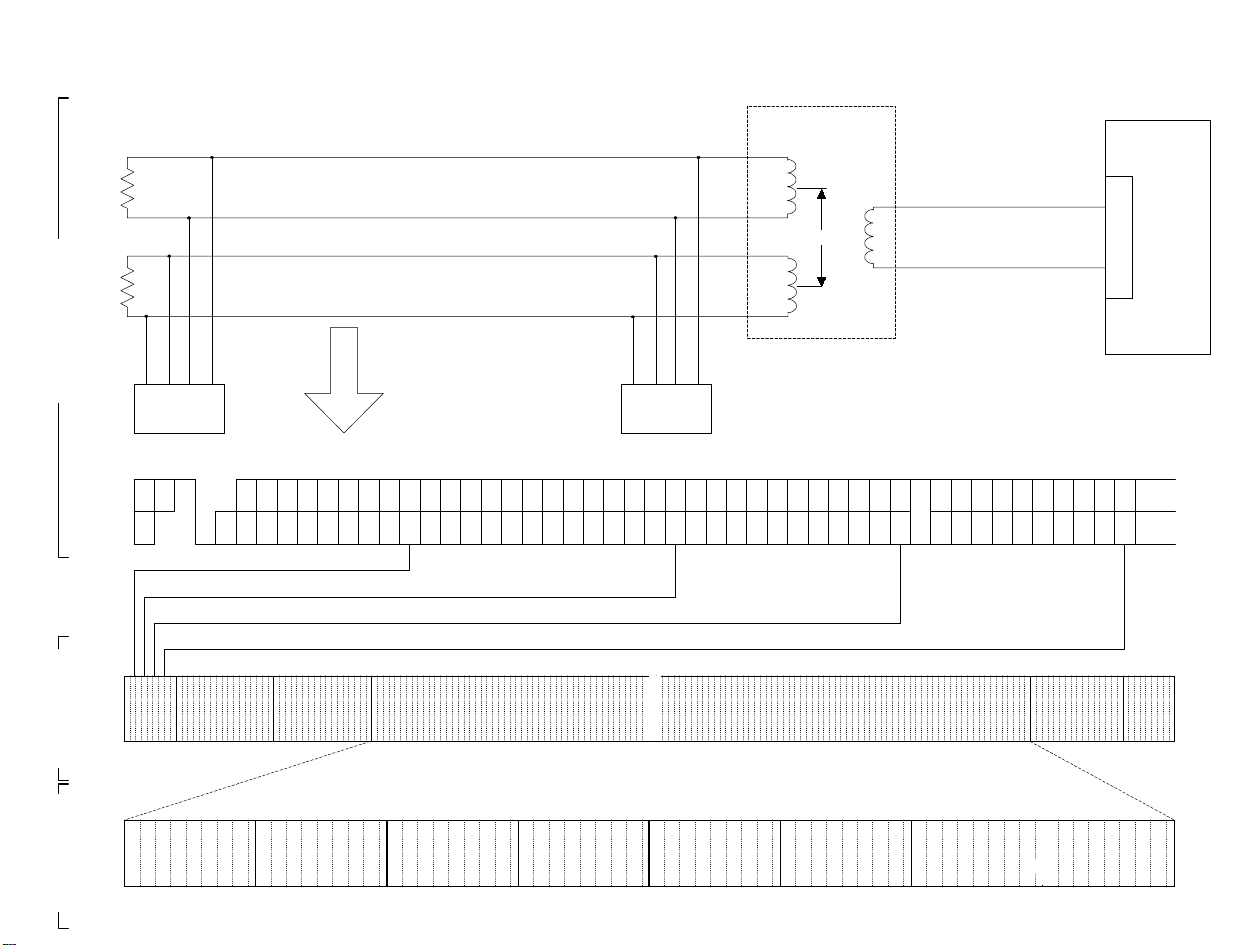
NTT
DSU
D70
Configuration of B channel, layers 1 to 7
··
··
··
I
S
N
→ → → → → →
B1 B1 B1 B1 B1 B1 B1 E DDL.F
→ → → → → →
Ping-pong transmission
L1
L2
Data (MMR)CDUI
TU
TA
TB
RA
RB
→ → → → → → → → → →
→ → → → → → → → → →
TE1 TE1
Ω
100
L
Ω
100
AYE
1
R
1380XX····0482XXXXXX····················································
PLD
12XX····
DLD
1203020100
010010XX··
CSUI
01 00
TDI
02F080
FLAG A C I FCS FLAG
DL. B1 B1 B1 B1 B1 B1 B1 B1 E D A FA N B2 B2 B2 B2 B2 B2 B2 B2 E D M B1 B1 B1 B1 B1 B1 B1 B1 E D S B2 B2 B2 B2 B2 B2 B2 B2 E L.FL.
0(-)
0(+)
1
L
AYE
011 1 111 0XX0 0 0000XXXX XXXXXXXX XXX···X XXXXXXXXXXXX XXXX0 1 1 111 1 0X
R
DT
2
L
AYE
Layer 3 Layer 4 Layer 5 Layer 6
2001XXXX
3
R
b_ch.wmf
IV - 1
Page 46

B channel, layer 2 (X.25 link level: LAPB)
F
1 octA1 octC1 oct
Address field
value (H)
Command from DTE
01
Response from DTE
Command from DTE
03
Response from DTE
F
1 octA1 octC1 oct
Information (I) "data"
Monitor (S) "Re-
sponse to (I)"
Unnumbered (U)
"Adaptive link con-
trol"
RR (Receive ready)
RNR (Receive not ready) 0 1 0 1
REJ (Retransmission request) 1 0 0 1
SABM (Set asynchronous
balanced mode)
UA (Unnumbered
acknowledgment)
DISC (Disconnect) 0 1 1 P 0 0 1 1
DM (Disconnect mode) 0 0 0 F 1 1 1 1
FRMR (Frame reject) 1 0 0 F 0 1 1 1
Definition
→
←
←
→
I
N oct
DCE
DCE
DCE
DCE
I
N oct
N (R) Receive order
FCS
2 oct
F
1 oct
C
DCEDTE
R
C
DCEDTE
R
FCS
2 oct
87654321
N (S) Transmission
number
N (R) Number that
can be accepted
001P1111
011F0011
P
order number
0001
P/F
F
1 oct
0
•
P/F (poll/final) bit .... Indicates the final frame and requests a response from the other
Note:
party.
IV - 2
Page 47

Monitor (S) "Re-
sponse to (I)"
Unnumbered (U)
"Adaptive link con-
trol"
——— Extended mode ... Modulo 128 format ———
16 ~ 10 9 87654321
Information (I) "data"
RR (Receive ready)
RNR (Receive not ready) 00000101
REJ (Retransmission request) 000010
SABM (Set asynchronous balanced
mode)
UA (Unnumbered acknowledgment) 0 1 1 F 0011
DISC (Disconnect) 0 1 0 P 0011
DM (Disconnect mode) 0 0 0 F 1111
FRMR (Frame reject) 100F0111
N (R) Receive
order number
N (R) Number
that can be
accepted
N (S) Transmission order
P
P/F
number
00000001
011P1111
0
0
1
Command (C)/Response (R) C R Function
(Receive Ready)
RR
: Receive ready
(Receive Not Ready)
RNR
: Cannot receive
(REJect)
REJ
: Retransmission request
(Set Asynchronous
SABM
Balanced Mode)
: Asynchronous balanced
mode setting
(SABM Extended)
SABME
: Extended asynchronous
balanced mode setting
(Unnumbered Acknow-
UA
ledgment)
: Unnumbered
acknowledgment)
(DISConnect)
DISC
: Disconnect
(Disconnect Mode)
DM
: Disconnect mode
(FRaMe Reject)
FRMR
: Frame reject
OO
OO
OO
O
O
O
Information frame can be received.
•
Acknowledges information frames up to N(R) - 1.
•
Indicates busy state, and continuous incoming
•
information frames cannot be accepted
temporarily.
Busy state is released by outputting RR, REJ,
•
SABM, or UA frame.
Since information frames after frame number N(R)
•
were not accepted, requests retransmission.
Sets up the Information transfer phase mode.
•
Used to set up the asynchronous balanced mode
•
(ABM). (Every command/response control field
length is 1 octet.)
Sets up the Information transfer phase mode.
•
Used to set up the extended asynchronous
•
balanced mode (ABM). (Control field length is 2
octets.)
Acknowledgment for mode setting/disconnect
•
O
Ends the operation mode that has been set up.
•
(Operation stopped state)
Notifies about logical disconnection from data link
•
and that the terminal is currently in the disconnect
O
phase.
Notifies that execution is not possible for mode
•
setting.
Any error that cannot be corrected by
•
O
retransmitting the same frame is informed by the
information field.
Informatio
n field
None
None
None
None
None
None
None
None
Yes
IV - 3
Page 48

V. B Channel, Layer 3
Page 49

B channel, layer 3 (X.25 packet level)
F
1 octA1 octC1 oct
I
N oct
Calling side Called side
Call setting and release
r
0B
0F
13
17
DTE → DCE DTE ← DCE DCE → DTE DCE ← DTE
identifier
Packet type
CR:
Call Request
CC:
Call Connected
CQ:
Clear Request
CF:
Clear Confirmation
XX DT: Data
23 IT: Interrupt
interrupt
27 IF: Interrupt Confirmation
Data and
X1 RR: Receive Ready
X5 RNR: Receive Not Ready
REJ:
X9
Reject
RQ:
1B
Reset Request
1F
Flow control and reset
FB
Restart
FF
SQ:
Restart Request
RF:
Reset Confirmation
SF:
Restart Confirmation
CN:
Incoming Call
CI:
Clear Indication
RI:
Reset Indi c a tion
SI:
Restart Indication
FCS
2 oct
F
1 oct
CA:
Call Accepted
CF:
Clear Confirmation
REJ:
Reject
RF:
Reset Confirmation
SF:
Restart Confirmation
V - 1
Page 50

Layer 3 connection and clearing procedure
∗
Call and clear procedure
•
Transparent transfer within network
Set-up call
Call
TE
Call request Incoming call
Network
Called
TE
CNCR
(accept incoming call)
Set-up call
(reject incoming call)
Reject
confir-
mation
Clear call Clear request Clear indication
Reset procedure
•
Reset
request
Connected
Call request Incoming call
Clear indication
Clear confirmation
CACC
CNCR
CQCI
CFCF
CICQ
Clear confirmation Clear confirmation
Call
TE
Network
Reset request Reset indication
Reset request
CFCF
RIRQ
RFRF
Incoming call accept
Clear confirmation
Reject incoming call
Incoming
TE
Reset confirmation
Clear
request
Restart procedure
•
Restart
request
SFSF
Incoming
TE
SISQ
Restart confirmation
Call
TE
Network
Restart request Restart indication
Restart request
V - 2
Page 51

Packet format
∗
Signal name or status
name, etc.
Call request
CR packet
[0B]
Definition
Packet used to request a call
oct87654321
General format identifier (GFI)
0 0 1 0
2
3
Logical channel number (LCN)
Packet type identifier (TYP)
Logical channel group
number (LCGN)
0 0 0 0 1 0 1 1
4 Calling side subscriber line
number length (CLL)
Called side subscriber line
number length (CDL)
Calling side subscriber line number (DA)
A
B
1
C1 D
1
1
E1 F
G1 0 0 0 0
Called side subscriber line number (SA)
A
B
2
C2 D
E2 F
G2 0 0 0 0
0 1 0 0 0 0 1 0
Called DTE packet size: Logarithmic, base 2 (e.g, if 8 is
stored here, pakcet size is 128)
Calling DTE packet size: Logarithmic, base 2 (e.g, if 8 is
stored here, pakcet size is 128)
0 1 0 0 0 0 1 1
Called DTE window size: Binary coded
Calling DTE window size: Binary coded
Call user data (DATA) field
C
CR:
all-Request
1
2
2
2
Facility length (FL)
Facility (packet size)
Facility (window size)
V - 3
Page 52

Signal name or status
name, etc.
Incoming call request
CN packet
[0B]
Definition
Packet used to inform of an incoming call
oct87654321
General format identifier (GFI)
0 0 1 0
2
Logical channel number (LCN)
Logical channel group
number (LCGN)
3 Packet type identifier (TYP)
0 0 0 0 1 0 1 1
4 Calling side subscriber line
number length (CLL)
Called side subscriber line
number length (CDL)
Calling side subscriber line number (DA)
A
B
1
C1 D
1
1
E1 F
G1 0 0 0 0
Called side subscriber line number (SA)
A
B
2
C2 D
E2 F
G2 0 0 0 0
Facility length (FL)
Facility (packet size)
0 1 0 0 0 0 1 0
Called DTE packet size: Logarithmic, base 2 (e.g., if 8 is
stored here, packet size is 128)
Calling DTE packet size: Logarithmic, base 2 (e.g., if 8 is
stored here, packet size is 128)
Facility (window size)
0 1 0 0 0 0 1 1
Called DTE window size: Binary coded
Calling DTE window size: Binary coded
Call user data (DATA) field
CN packet form
n
CN: I
coming Call
1
2
2
2
V - 4
Page 53

Signal name or status
name, etc.
Incoming call
request
CA packet
[0F]
Definition
Packet used to inform of incommng call acceptance
oct87654321
General format identifier (GFI)
0 0 1 0
2
3
0 0 0 0 1 1 1 1
4
C
CA:
all Accept
Logical channel number (LCN)
Packet type identifier (TYP)
Same coding as that of the CR/CN packet
Logical channel group
number (LCGN)
Signal name or status
name, etc.
Connection complete
CC packet
[0F]
Definition
Packet used to inform that connection is complete
oct87654321
General format identifier (GFI)
0 0 1 0
2
3
0 0 0 0 1 1 1 1
4
C
CC:
all Connected
Logical channel number (LCN)
Packet type identifier (TYP)
Same coding as that of the CR/CN packet
Logical channel group
number (LCGN)
V - 5
Page 54

Signal name or status
name, etc.
Clear request
CQ packet
[13]
Definition
Packet used by terminal equipment to reject the incoming call or to
request to clear the call
oct87654321
1 General format identifier (GFI)
0 0 1 0
2
3 Packet type identifier (TYP)
0 0 0 1 0 0 1 1
4 Cause of clearing (CAUSE)
0 0 0 0 0 0 0 0
5
6
0 0 0 0 0 0 0 0
7
C
CQ:
all Request
Logical channel number (LCN)
Diagnostic code (DIAG)
Clear user data (DATA) filed
Logical channel group
number (LCGN)
Signal name or status
name, etc.
Clear request
CI packet
[13]
Definition
Packet used by line terminal equipment to request to clear the call
oct87654321
1 General format identifier (GFI)
0 0 1 0
2
3 Packet type identifier (TYP)
0 0 0 1 0 0 1 1
4
0 0 0 0 0 0 0 0
5
6
0 0 0 0 0 0 0 0
7
C
CI:
all Indication
Logical channel number (LCN)
Cause of clearing (CAUSE)
Diagnostic code (DIAG)
Clear user data (DATA) filed
Logical channel group
number (LCGN)
V - 6
Page 55

Signal name or status
name, etc.
Clear confirmation
CF packet
[17]
Clear confirmation
CF packet
Definition
Packet used by line terminal equipment to confirm the call clearance
oct87654321
1 General format identifier (GFI)
0 0 1 0
2
3 Packet type identifier (TYP)
0 0 0 1 0 1 1 1
C
all Confirmation
CI:
Packet used by terminal equipment to confirm the call clearance
The format is the same as the clear confirmation (CF) packet format.
Logical channel number (LCN)
Logical channel group
number (LCGN)
Signal name or status
name, etc.
Reset request
RQ packet
[1B]
Reset indication
RI packet
Definition
Packet used by terminal equipment to request resetting of the
transmit/receive order number
oct87654321
1 General format identifier (GFI)
0 0 1 0
2
3
0 0 0 1 1 0 1 1
4
R
eset Request
RQ:
Packet used by line terminal equipment to request resetting of the
transmit/receive order number
The format is the same as the reset request (RQ) packet format.
Logical channel number (LCN)
Packet type identifier (TYP)
Reset cause (CAUSE)
Diagnostic code (DIAG)
Logical channel group
number (LCGN)
V - 7
Page 56

Signal name or status
name, etc.
Reset confirmation
RF packet
[1F]
Definition
Packet used for confirming resetting of the transmit/receive order number
oct87654321
1 General format identifier (GFI)
0 0 1 0
2
3 Packet type identifier (TYP)
0 0 0 1 1 1 1 1
RF: Reset Con
Logical channel number (LCN)
f
irmation
Logical channel group
number (LCGN)
Signal name or status
name, etc.
Interrupt
IT packet
[23]
Signal name or status
name, etc.
Interrupt confirmation
IF packet
[27]
Definition
Packet used for sending data when transmission is restricted (when RNR
is received)
oct87654321
1 General format identifier (GFI)
0 0 1 0
2
3 Packet type identifier (TYP)
0 0 1 0 0 0 1 1
4
Int
IT:
errupt
Packet used for confirming interrupt data
oct87654321
1 General format identifier (GFI)
0 0 1 0
2
Logical channel number (LCN)
Interrupt user data (IDT)
Definition
Logical channel number (LCN)
Logical channel group
number (LCGN)
Logical channel group
number (LCGN)
3 Packet type identifier (TYP)
0 0 0 1 1 1 1 1
I
IF:
nterrupt Confirmation
V - 8
Page 57

Signal name or status
name, etc.
Restart request
SQ packet
[FB]
Definition
Packet used for requesting terminal equipment to clear all calls
oct87654321
1 General format identifier (GFI)
0 0 1 0 0 0 0 0
2
0 0 0 0 0 0 0 0
3 Packet type identifier (TYP)
1 1 1 1 1 0 1 1
4 Restart cause (CAUSE)
0 0 0 0 0 0 0 0
5
s
SQ: Re
tart Request
Diagnostic code (DIAG)
Signal name or status
name, etc.
Restart indication
SI packet
[FB]
Signal name or status
name, etc.
Restart confirmation
SF packet
[FF]
Definition
Packet used for indicating to line terminal equipment to clear all calls
oct87654321
1 General format identifier (GFI)
0 0 1 0 0 0 0 0
2
0 0 0 0 0 0 0 0
3 Packet type identifier (TYP)
1 1 1 1 1 0 1 1
4 Restart cause (CAUSE)
0 0 0 0 0 0 0 0
5
s
tart Indication
SI: Re
Packet used for confirming that all calls are cleared
oct87654321
1 General format identifier (GFI)
0 0 1 0 0 0 0 0
2
0 0 0 0 0 0 0 0
3 Packet type identifier (TYP)
1 1 1 1 1 1 1 1
Diagnostic code (DIAG)
Definition
s
tart Confirmation
SF: Re
V - 9
Page 58

Signal name or status
name, etc.
Facility request
FQ packet
[43]
Definition
Packet used for request to register/clear closed area connection service
oct87654321
General format identifier (GFI)
0 0 1 0
2
Logical channel number (LCN)
Logical channel group
number (LCGN)
3 Packet type identifier (TYP)
0 1 0 0 0 0 1 1
4 Calling side subscriber line
number length (CLL)
Called side subscriber line
number length (CDL)
Called side subscriber line number (DA)
A
B
1
C1 D
1
1
F
FQ:
acility Request
E1 F
1
G1 0 0 0 0
Calling side subscriber line number (SA)
A
B
2
C2 D
E2 F
2
2
2
G2 0 0 0 0
Facility length (FL)
0 0 0 0 0 0 1 1
Facility code (F)
0 1 0 0 0 0 0 0
Party specification number
N
N
1
N3 N
2
4
V - 10
Page 59

Signal name or status
name, etc.
Receive ready
RR packet
[01]
Definition
Packet used to indicate that data can be confirmed and received
oct87654321
1 General format identifier (GFI)
0 0 1 0
2
3 Packet type identifier (TYP)
0 0 0 0 0 0 0 1
4
R
eceive Ready
RR:
Logical channel number (LCN)
Receive order number P (R) 0
Logical channel group
number (LCGN)
Signal name or status
name, etc.
Receive not ready
RNR packet
[05]
Definition
Packet used to indicate that data cannot be confirmed and received
oct87654321
1 General format identifier (GFI)
0 0 1 0
2
3 Packet type identifier (TYP)
0 0 0 0 0 1 0 1
4
R
eceive Not Ready
RNR:
Logical channel number (LCN)
Receive order number P (R) 0
Logical channel group
number (LCGN)
V - 11
Page 60

Signal name or status
name, etc.
Data
DT packet
Definition
Packet used to transfer data between subscribers
oct87654321
1 General format identifier (GFI)
Q 0 1 0
2
Logical channel number (LCN)
Logical channel group
number (LCGN)
[XX]
3
4
5
.
.
.
.
.
.
.
.
.
Dat
DT:
Q: Qualifier bit
M: More data indication
a
Transmit order number P (S)
Receive order number P (R) M
0
User data (DATA)
V - 12
Page 61

VI. B Channel, Layer 4
Page 62

1. Transport lay er control block
Block Block
Code
H
Estab-
lishment
control
Information
transfer
Error
notification
EO
F0
70
(T Connection Request)
TCR
: Connection request
TDT (T Data Block)
: Data transfer
TBR (T Block Reject)
: Error notification
2. Transport service sequence
B channel, layer 4
Name
Code
H
D0
80
CCITT recommendation T.70
Name
TCA (T Connection Accept)
: Connection accept
TCC (T Connection Clear)
: Connection clear
a) TC establis hment successful
TS user TS user
T-CONNECT request
T-CONNECT confirmation
TS provider
TCR
T-CONNECT indication
T-CONNECT response
TCA
TSAPTSAP TSAPTSAP
c) Transfer phase
Calling side or called side
T-DATA
request
TS user
d) Error notification
TSAP
b) TC establishment failure
T-CONNECT indication
TDT (EM=0)
TDT (EM=0)
TDT (EM=0)
TDT (EM=1)
TS provider
TS user TS user
T-CONNECT request
TS provider
TCR
T-CONNECT request
T-CONNECT request
TCA
Calling side or called side
T-DATA
indication
TS user
TSAP
TS userTS user TS provider
TBR
VI - 1
T-EXCEPTION indicationT-EXCEPTION indication
TSAPTSAP
Page 63

3. Transport layer block format
Octet 1Octet 2Octet 3Octet 4Octet 5Octet 6Octet 7
Parameter (See
Length
TCR
(127 max.)
Length
TCA
(127 max.)
Note 1-1: Parameter for address extension Note 1-2: Parameter for TDT block
Octet 1
2
3
n
Length
TCC
(127 max.)
E0 0 0 0 0
Unused
IA5 digit ... 1
IA5 digit ... 2
IA5 digit ... n
80
Destination reference
information
Destination reference
information
DO
Extended address parameter type
Parameter length indicator
Transmission originator
source reference
information
Transmission source
reference information
C1H: Calling address
C2H: Called address
Transmission source
reference information
Extended
Extended
Octet 1
XXXX
length negotiation
Cause of
clearing
Note 2
Notes 1-1 and 1-2)
Only when requesting
0 0
and confirming
optional transport
field
connection function
Parameter (See
Notes 1-1 and 1-2)
Only when requesting
0 0
and confirming
optional transport
field
connection function
1 1 0 0 0 0 0 0
0 0 0 0 0 0 0 1
2
0 0 0 0 X X X
3
1011: 2048 octets
1010: 1024 octets
1001: 512 octets
1000: 256 octets
0111: 128 octets
Parameter
Used when sending
optional additional
clear information
Octet n
X
TBR
Note 2: Cause of clearing
00H .... Cause is not indicated
01H .... Terminal is occupied
02H .... Terminal has a problem
03H .... Address not known
Length
(127 max.)
Note 3: Cause of rejection
00H .... Cause is not indicated
01H .... Function is not implemented
02H .... Invalid block
03H .... Invalid parameter
70
Destination reference
information
VI - 2
Reject cause
Note 3
Parameter (Option)
Octet 1
Parameter field
Used to indicate bit pattern of
block rejected including the octet
which is the cause of rejection
Octet 1
1 1 1 0 0 0 0 0
Parameter length
2
identifier
3
Additional clear
information
n
Parameter (Mandatory)
1 1 0 0 0 0 0 1
Parameter length
2
indicator
3
Rejected information
n
Page 64

TDT
Length
02
X0000000 Data (TSDU)
F0
TSDU end indication, 1 indicates end of TSDU.
Note:
The value of "Trans mi ss io n or so urc e reference information " is t he loc al system’s parameter. Received transmission or source reference information is
used as the "destination reference information" for a response to the block.
VI - 3
Page 65

VII. B Channel, Layer 5
Page 66

B channel, layer 5
CCITT recommendation T.62
1. Session control commands/responses
Command Response
Code Name Code Name
Session Set-up and release
0D CSS (Command Session
Start): Starts the session
09 CSE(Command Session
End): Ends the session
19 CSA(Command Session
Abort): Aborts the session
0E RSSP(Response Session Start
Positive): Acknowledges
session start
0C RSSN(Response Session
Start Negative): Denies
session start
0A RSEP(Response Session
End Positive): Acknowledges
session end
1A RSAP(Response Session
Abort Positive):
Acknowledges session abort
Information transfer
01 CSUI(Command Session
User Information): Session
user information
02 RSUI(Response Session
User Information): Session
user information
Management
15 CSCC(Command Session
Change Control): Controls
session change
16 RSCCP(Response Session
Change Control Positive) :
Acknowledges session
change control
VII -1
Page 67

2. Document control commands/responses
Command Response
Code Name Code Name
Document control
2D CDS(Command Document
Start): Starts the document
1D CDC(Command Document
Continue ): Continues the
document
3D CDCL(Command Document
Capability List ): Lists
document functions
29 CDE(Command Document
End): Ends the document
39 CDD(Command Document
Disuse): Discard the
document
19 CDR(Command Document
Resynchoronize): Document
resynchronization
3E RDCLP(Response Document
Capability List Positive):
Acknowledges the document
function list
(Negative response for CDS
or CDC uses RDGR)
2A RDEP(Response Document
End Positive): Acknowledges
document end (Negative
response uses RDPBN)
3A RDDP(Responce Document
Disuse Positive):
Acknowledgement of CDD
1A RDRP(Response Document
Resynchronize Positiv e):
Acknowledges document
resynchronization
Information transter
01 CDUI(Command Document
User Information): Document
user information
Error recovery
31 CDPB(Command Document
Page Boundary): Document
page boundary
32 RDPBP(Response Document
Page Boundary Positive):
Acknowledges document
page boundary
30 RDPBN(Response Document
Page Boundary Negative):
Denies document page
boundary
00 RDGR(Response Document
General Reject): Denies
general document use
VII - 2
Page 68

Session operation mode
Caller (source) Party(sink)
Session set-up
Start
CSS
RSSP/RSSN
Positive/negative
..........................................................................................................
Session data transfer
Data
Data
CSUI (document control)
RSUI (document control)
Data
Data
..........................................................................................................
Session control change
Change request
Change request
..........................................................................................................
Session end
(Successful termination)
End
CSCC
RSCCP
CSCC
RSCCP
CSE
RSEP
Control positive
:
:
:
(ready to shift transmission state)
*This side is now the source
Change request
(The other side becomes the
source)
End positive
..........................................................................................................
Session abort
(Unsuccessful
termination)
End
CSA
RSEP
End positive
VII -3
Page 69

Document control procedure
Caller (source) Party (sink)
Document function
check
Function List
CSUI/CDCL
RSUI/RDCLP
Positive
..........................................................................................................
Document parameters
Start
CSUI/CDS
..........................................................................................................
Document tramsfer
Document information
Page information
Image (1)
Page boundary
Page information
Image (2)
CSUI/CDUI
CSUI/CDUI
CSUI/CDUI
CSUI/CDPB
RSUI/RDPBP
CSUI/CDUI
CSUI/CDUI
Page boundary positive
..........................................................................................................
Document end
End
CSUI/CDE
RSUI/RDEP
End positive
CSUI and RSUI are session commands/responses
VII - 4
Page 70

Session and document coding rules
(1) Relationship between session control and document control
Text
Session:
Document:
CI LI Parameter field User information field
Session field (handed over to transport service: TSDU)
CI LI Parameter field User information field
Document field
Document command/response
Session command/response
(2) Examples of command/response structure
CI/RI (identifier) Header information to identify the
command/response
LI (length indicator) Indicates the number of octets
PGI (parameter group
Indicates which group of parameter identifiers
identifier)
PI (parameter identifier) Indicates the information type
PV (parameter value) Indicates the value of the parameter identified
by PI/PGI
When the value of LI is 0 (that is, when there is no parameter field)
CI LI
VII -5
Page 71

When there is only on e parameter field consis t i ng of a PV of 1 oc tet in length; from the left, values of the LIs from the left are 3 and
1.
CI LI PI LI PV
When there are two different param eter fields, on e wi th a PV of 1
octet in length, and the other with a PV of 3 octets in length.
From the left, the values of the LIs are 8, 1, and 3.
CI LI PI LI PV PI LI P V
One PGI containi ng two Pls
CILIPGILIPILIPVPILIP V
The simplest example for car rying user information
CI LI User information
When LI is undefined (80 or 82)
80 PV or user information 0000
XXXXH oct
82 XXXX PV or user information
VII - 6
Page 72

Non standard capability identifier (NSC) determination
1. NSC organization
oct1 oct2 oct3 oct4 oct5 oct6 oct7 oct8 oct9 oct10 oct11 oct12 oct13
National
PGI LI
E8 (12+n) 00 01 25 00 01 00 00 00 00 00 00 00 NSC area
Country
code
option
Supplier code Version code
code
01: Japan
Others: Othe r countries
Fixed at 12 octet s
00: K83 D
01: K200 I
03: CF0, LH0, CG0 (US only), FX4
RI expansion
MAX n = 254 - 12
2. TTI in Japanese f or RI G4
oct13 oct14 oct15.....................................................
RI TTIF0LI
PV1 PV2 PV3 PV4 PVn-2 PVn-1 PVn
n
n=MAX 32 oct
Items in the above diagram are used only in CSS/RSSP
n
VII -7
Page 73

3. NSC and contents of SUD and DP
The SUD addition and judgment conditions are determined by the
NSC check result as follows:
NSC check result Contents of SUD and DP
Country code
Japan
00
Other coun-
tries
Other than 00
National
option code
01
00
Undefined Undefined
Supplier code
Same in both
terminals
Different in both
terminals
Same in both
terminals
Different in both
terminals
CCITT
option
OO O
OO X
OX O
OX X
OX X
National
option(Japan)
Manufacuturer
option
The manufacturer option is referred to as PUPR (Private Use Parameter RI) from K200 I. PUPR becomes effective only when bit 0
of oct 5 of the version code is 1.
VII - 8
Page 74

Table 1-1: Session Layer Commands
CI/RI PGI PI PV
CSS
VII - 9
CSE
CSA
CSCC 15
CSUI 01
Session
reference
Non standard
session
capabilities
0D
Session user
data (SUD)
09
19
Calling
terminal
01
identifier
Date and time
Window size
02
Service
identifier
C1
Non standard
capability
identifier (NSC)
Session end
parameter
Same as
above
Note concerning the "A" column
O: Must be transmitted
∆
: Sent depending on condition
X: Not sent
0A
0B
0E
08
E8
RI TTI F0, L1, shift JIS after oct 13
Ext
NSC
11
JIS 8, 24 digits
JIS 8, 14 digits
1 to 255 in binary
Telematic 01
Refer to Table 2-1
Refer to Table 3-1
No PI
Fixed PV Length
Case a: 6 oct
Case b: 12 oct
Transport disconnect
Terminal error
Procedure error
Undefined reason
Same as above
A Transmit Condition B Receive Condition
PV is IA5
O
OO
01
O
01
O
Refer to Table 2-1
O
Japan code 2500
National option code
Supplier code 2500
Version code xx00
Note concerning the "B" column
O: Must be received. If not received, an error is generated and DISC is output.
∆
: Even if not received, the procedure is treated as normal.
X: When received, an error occurs and CSA is output.
00 or 01
00 - 01 - 25 - 00
xx - 00 - 00 - 00
00 - 00 - 00 - 00
O
xx = 00: K83D;
01: K200I; 02: CF0,
LH0, CG0, FX4
oct15=PV1…PVn
Shift JIS n=Max 32
01
O
09/05
O
PV contents are
O
arbitrary
PV contents are
arbitrary
PV value is ignored
O
Other than 0 indicates
O
an error
*1
O
Refer to Table 3-1
Refer to ‘NSC and the
contents of SUD and
DP’ for details of the
∆
checking method
*2
Same as above
∆
(RI Ext NSC)
PV value is ignored
∆
PV value is ignored
∆
Page 75

Notes:
*1: - If there is no session user data, response is made with RSSN (for basic teletex).
*2: - The R: NSC save area must be separated from that of SSN (R: CSS/RSSP).
- If R:NSC exists for R: CDCL/RDCLP, it is treated in the same way as shown in ’NSC and the contents of SUD and DP’.
If it does not exist, it is treated in the same way as SSN.
VII - 10
Page 76

Table 1-2: Session Layer Responses
CI/RI PGI PI PV
RSSP
VII - 11
Session
reference
Non standard
session
capabilities
0E
Session user
data
(SUD)
Called terminal
identifier
01
Date and time
Window size
02
Service identifier
Session request
function
C1
Non standard
capability
identifier (NSC)
JIS 8, 24 digits
09
JIS 8, 14 digits
0B
1 to 255 in binary
0E
Telematic 01
08
Transmit request b1=1
10
Refer to Table 2-1
Refer to Table 3-1 O
No PI
Fixed PV length
Case a : 6 oct
E8
Case b : 12 oct
RI PI=F0H
TTI
Ext
NSC
Japan code 00
National option 00 or 01
Supplier code 2500
Version code xx00 O
F0, LI, shift JIS after oct 13
A Transmit Condition B Receive Condition
PV is IA5
O
OO
01
O
01
O
01 (When there is a
∆
document to send)
Refer to Table 2-1
00. 01. 25. 00
xx. 00. 00. 00
00. 00. 00. 00
xx = 00: K83D
01: K200I
02: CF0, LH0,
CG0, FX4
oct 15=PV1…PVn
Shift JIS n=Max 32
PV contents are
O
arbitrary
PV contents are
arbitrary
PV value is ignored
O
Other than 0 indicates
O
an error
∆
O*1Refer to Table 3-1
Refer to ‘NSC and the
contents of SUD and
DP’ for details of the
checking method
∆
*2
Same as above
∆
(RI Ext NSC)
Page 77

CI/RI PGI PI PV
RSSN
VII - 12
RSEP 0A
RSAP 1A
RSCCP 16
RSUI
Session
reference
Non standard
session
0C
capability
Session user
data
(SUD)
02
01 Cal led terminal
identifier
Date and time
02 Window size
Service identifier
Reason
C1 Refer to T ab le 2-1
Session function
request
Note concerning the "A" column
O: Must be transmitted
∆
: Sent depending on condition
X: Not sent
090BJIS 8, 24 digits
JIS 8, 14 digits
1 to 255 in binary
0E
Telematic 01
08
Refer to (DD/CDR/RDPBN)
32
(Refer to Table 3-1)
Transmit request b1=1
10
Note concerning the "B" column
O: Must be received. If not received, an error is generated and DISC is output.
∆
: Even if not received, the procedure is treated as normal.
X: When received, an error occurs and CSA is output.
Notes:
*1: - If there is no session user data, response is made with CSE (for basic teletex).
*2: - The R: NSC save area must be separated from that of SSN (R: CSS/RSSP).
- If R:NSC exists for R: CDCL/RDCLP, it is treated in the same way as shown in ’NSC and the contents of SUD and DP’.
If it does not exist, it is treated in the same way as SSN.
A Transmit Condition B Receive Condition
OOPV contents are
O Sends back contents
of CSS
01
O
01
O
00
O
O
Refer to Table 2-1
01 (Where there is a
∆
document to send)
arbitrary
PV contents are
arbitrary
PV value is ignored
O
Other than 0 indicates
O
an error
PV value is ignored
∆
O
(Refer to Table 3-1)
∆
Page 78

Table 1-3: Document Layer Commands
CI/RI PGI PI PV
VII - 13
CDS
CDC
CDE
CDR
2D
Session user
data (SUD)
Document
linking
1D
Session user
data (SUD)
29
19
Document
reference number
Document type
C1
Called terminal
identifier
Calling terminal
identifier
21
Date and time 0B JIS 8, 14 digits
Document
reference number
Checkpoint
reference number
Document
reference number
(current)
C1
Checkpoint
reference number
Reason
JIS 8, decimal 3 digits
29
01: Operator 02: Control
30
03: Monitor
Refer to Tabl e 2-1
Refer to Tabl e 3-4
JIS 8, 24 digits
09
JIS 8, 24 digits
0A
JIS 8, decimal 3 digits
29
JIS 8, decimal 3 digits
2A
JIS 8, decimal 3 digits
29
Refer to Tabl e 2-1
Refer to Tabl e 3-4
JIS 8, decimal 3 digits
2A
03: Sequence 05: Terminal
32
06: Procedure 00: No reason X
A Transmit Condition B Receive Condition
Fixed at 001 (except
in batch transmission)
O
In batch transmission,
increments (+1) from
001
Default = Normal
X
document
Refer to Table 2-1
O
CDC is not used When receiving,
X
001∼999
O
(Number of
transmitted pages)
CDR is not used
PV value is not
checked
O
X
Refer to Table 3-4
O
process as a received
CDS
Refer to Table 3-4
O
When receiving,
RDDP or CSA
∆
returned
Page 79

CI/RI PGI PI PV
VII - 14
CDD
CDPB
CDCL
CDUI
39
31
Session user
data (SUD)
3D
Document
01
profile
Reason
Checkpoint
reference number
C1
Non standard
capability identifier
(NSC)
A0
Note concerning the "A" column
O: Must be transmitted
∆
: Sent depending on condition
X: Not sent
2A
E8
03: Sequence 05: Terminal
32
06: Procedure 00: No reason
JIS 8, decimal 3 digits
Refer to Tabl e 2-1
Same as CSS/RSSP (except RI Ext NSC)
Refer to Tabl e 2-1
Note concerning the "B" column
O: Must be received. If not received, an error is generated and DISC is output.
∆
: Even if not received, the procedure is treated as normal.
X: When received, an error occurs and CSA is output.
Notes:
*1: - CDCL is not always received.
- CDCL without session data may be received not to negotiate for the presentation function, but to negotiate other functions
(timer, memory, etc.).
*2: - The R: NSC save area must be separated from that of SSN (R: CSS/RSSP).
- If R:NSC exists for R: CDCL/RDCLP, it is treated in the same way as shown in ’NSC and the contents of SUD and DP’.
If it does not exist, it is treated in the same way as SSN.
A Transmit Condition B Receive Condition
CDR is not used
X
001∼999
O
(Number of
transmitted pages)
Refer to Table 2-1
O
Same as left
O
When receiving,
RDDP or CSA
∆
returned
O
*1
∆
Refer to Table 3-2
*2
∆
Page 80

Table 1-4: Document Layer Responses
CI/RI PGI PI PV
RDEP
2A
RDRP 1A
RDDR 3A
RDPBP 32 Checkpoint
VII - 15
RDPBN
RDCLP
*1
RDGR
30
Session user
data (SUD)
3E
00
Checkpoint
reference number
reference number
Receive capability
limit
Reason
C1 Refer to Table 2-1
Non standard
capability
identifier (NSC)
Returned
parameters
Note concerning the "A" column
O: Must be transmitted
∆
: Sent depending on condition
X: Not sent
JIS 8, decimal 3 digits
2A
JIS 8, decimal 3 digits
2A
00: OK to continue 01: NG to continue
2E
03: Sequence 05: Terminal
32
06: Procedure 00: No reason
Same as CSS/RSSP (except RI Ext NSC)
E8
Pattern up to error byte
31
A Transmit Condition B Receive Condition
001∼009
O
(Number of
transmitted pages)
Output when
∆
receiving CDR
Output when
∆
receiving CDD
001∼009
O
(Number of
transmitted pages)
OO
03. 05. 06. 00
O
Refer to Table 2-1
O
Same as left
O
∆
Note concerning the "B" column
O: Must be received. If not received, an error is generated and CSA is output.
∆
: Even if not received, the procedure is treated as normal.
X: When received, an error occurs and CSA is output.
O
X
X
O
S: CSA is returned
∆
*2
∆
Refer to Table 3-3
*3
∆
D
Page 81

Notes:
*1: - Must be always sent when CDCL is received, and must be always received when CDCL is sent.
*2: - RDCLP without session user data may be received.
*3: - The R: NSC save area must be separated from that of SSN (R: CSS/RSSP).
- If R:NSC exists for R: CDCL/RDCLP, it is treated in the same way as shown in ’NSC and the contents of SUD and DP’.
If it does not exist, it is treated in the same way as SSN.
VII - 16
Page 82

Table 2-1: Session User Data (SUD) Adaptive Method
Presentation
capability descriptor (A4)
Note : Code
for document
profile (A2)
VII - 17
PGI PGI PGI PGI PI LI PV
Non basic
terminal
characteristics
(A2)
Page size
(A2)
Sequence
(30)
Sequence
(30)
Sequence
(30)
Sequence
(30)
Sequence
(30)
Sequence
(30)
Basic terminal
characteristics (80)
Interchange format (81) 01 00 Must be attached TIF.0
Fixed measurement
ratio (80)
Variab le measurement
ratio (81)
Fixed measurement
ratio (80)
Variab le measurement
ratio (81)
Fixed measurement
ratio (80)
Variab le measurement
ratio (81)
Fixed measurement
ratio (80)
Variab le measurement
ratio (81)
Fixed measurement
ratio (80)
Variab le measurement
ratio (81)
Fixed measurement
ratio (80)
Variab le measurement
ratio (81)
01 02 Must be attached
02 26C0
02 36CE
02 2F6C
02 432C
02 2F6D
02 432C
02 36CE
02 4D80
02 2E23
02 4125
02 27D8
02 3390
Adaptive Condition
CSS RSSP CDCL RDCLP CDS
XX
XX
XX
XX
XX
XXX
◊◊∆
♦♦∆
◊◊∆
◊◊∆
◊
X
X
◊◊
Remarks
Facsimile
ISO A4 (default)
JIS B4 (old B4)
JIS B4 (Japanese
equivalent of Legal size)
ISO A3
RDCLP : With external
printer
ISO B4
ISO North American A4
(Letter size)
Page 83

Adaptive Condition
◊◊∆
◊◊∆
♦♦∆
♦♦∆
♦♦∆
XXOOO
Presentation
capability descriptor (A4)
Note : Code
for document
profile (A2)
(Continued)
VII - 18
PGI PGI PGI PGI PI LI PV
Non basic
terminal
characteristics
(A2)
(Continued)
Extended
presentation
characteristics
(E4)
National
application
profile (EA)
Coding characteristics
(A3)
Presentation
characteristics (A4)
Extended coding
attributes (E0)
Extended presentation
attributes (E1)
Refer to Table 2-2
◊ : (CCITT option) Attached when existing as self mode.
♦ : (Japan option) Attached when possible as national option in Japan and exists as self mode.
O : (Manufacturer option) Attached when possible as manufacturer option and exists as self mode.
∆ : Attached as a logical product (common capability) of S: CDCL (self function) and R: RDCLP (other party function).
X : Not attached.
Compression (80)
Transfer picture
element density (8B)
Transfer picture
element density (8B)
Transfer picture
element density (8B)
Integer (02)
Integer (02)
Subscan line density
(C0)
01 01 X X X X X
01 02 X X X X X
01 03 X X
01 04 X X
01 02 X X
01 03 X X
01 01 X X
CSS RSSP CDCL RDCLP CDS
Note:
*1: Page size for RDCLP is determined by the paper feed cassette (except North American Letter size [NA_Lt]).
Remarks
Compression
240 dpi
300 dpi (K200I Europe)
400 dpi
MH (National option)
MR (National option)
100 dpi
(National option)
Manufacturer option
(PUPR)
depending on R: NSC
condition
Page 84

Table 2-2: Adaptive Method of
Extended Application Profile
PGI PGI PGI PGI PGI PI LI PV
Extended applicaiton
profile
(EA)
PUPR
VII - 19
Document
application
(E0)
Communication
application (E1)
Confidential application
(C0/E0)
Password applic ation
(C1/E1) *1
Document content
attribute (E2) ♦5
Transfer application (E0) Function (C0)
Originator(C2/E2)
Sequence
(30)
Sequence
(30)
Function (C0)
Password (C1)02Octet String XXXXO
(File ID: D7000)
Password (C1)
Density T ype
(C1)
Password (C1) 02 Octet String X X O X O
Dial ID (C0)
Dial No. (C1)
Subaddress No.
(C2)
Dial ID (C0)
Dial No. (C1)
Subaddress No.
(C2)
Adaptive Condition Remarks
CSS/
CDCL RDCLP CDS DP
RSSP
00/01/02
01
Octet String
02
00/01
01
00/01/02/04
01
01/02
01
Numeric String 30 to 39 and blank space
<16
01/02
01
Numeric String 30 to 39 and blank space
<16
XXOXX
♦1
X
XXXXO
XXOXX
XXXXO
XXXXO
♦2
O
O
XX
underlined items are
(The
default settings.)
00: None 01: Pending
02: OK
00/FF: No password
00/FF: No password
00: mm system
01: inch system (*1)
00: None 01: Pending
02: OK
00/FF: No password
01: Analog 02: Digital
•
PS 04: D•CS
08: D
(*2)
01: Analog 02: Digital
•
PS 04: D•CS
08: D
(*2)
Page 85

PGI PGI PGI PGI PGI PI LI PV
Extended applicaiton
profile
(EA)
PUPR
Communication
application (E1)
(Cont’d)
Destination (E3)
Sequence
(30)
Sequence
Dial ID (C0)
Dial No. (C1)
Subaddress No.
(C2)
Dial ID (C0)
(30)
(Cont’d)
Dial No. (C1)
Subaddress No.
(C2)
VII - 20
Sequence
(30)
Dial ID (C0)
Dial No. (C1)
Subaddress No.
(C2)
Sequence
Dial ID (C0)
(30)
Dial No. (C1)
Subaddress No.
(C2)
Transfer application (E0)
(Continued)
Password applic ation
Specific 2-stage
attribute (C4)
Password (C1)
(E1) (*2)
RI
extended
terminal
capability
(E2)
Device characteristics
(E1)
Engine type(C0) 01 00/01 X O O X X
mm/inch
conversion
function
(C1)
Adaptive Condition Remarks
(The underlined items are
default settings.)
01: Analog 02: Digital
•
PS 04: D•CS
08: D
01
01/02
CSS/
CDCL RDCLP CDS DP
RSSP
XXXXO
Numeric String 30 to 39 and blank space
<16
01
01/02
XXXXO
(*2)
01: Analog 02: Digital
•
PS 04: D•CS
08: D
Numeric String 30 to 39 and blank space
<16
01
01/02
XXXXO
(*2)
01: Analog 02: Digital
•
PS 04: D•CS
08: D
Numeric String 30 to 39 and blank space
<16
01
01/02
XXXXO
(*2)
01: Analog 02: Digital
•
PS 04: D•CS
08: D
Numeric String 30 to 39 and blank space
<16
01
00, 01
02, 03
XXXXO
(*2)
00: No request
01: Reserved
02: 2-stage transfer
03: 2-stage transfer report
(Net ID: K200)
02
Octet String
X
♦3O♦4
O
XX
00/FF: No password
(*3)
00: mm 01: inch (*4)
00: No function
01: Function provided
(*4)
01
00/01
XOOXX
Page 86

Notes
*1 to *4 are employed from K200I.
From K200I ♦1 is used as File ID, and ♦2 as General Net ID.
If two different codes are used for a PGI/PI, eg. document content attribute on page VIII-19,if the first code is used, this will be referred to as case a. Also, if the
second code is used, this will be referred to as case b.
1: In case a, Net ID is stored at ♦1 (that is, the same value as at ♦3 is stored).
♦
2: In case a, polling ID (Net ID or File ID) is stored at ♦2 (that is, the value at ♦4 determines the Net ID).
♦
3: In case b, Net ID is stored at ♦3 ( ♦1 is unused).
♦
4: In case b, Net ID is stored at ♦4 (or at ♦2 when using File ID).
♦
5: In case a, ♦5 is not attached.
♦
VII - 21
Page 87

Table 3-1: CSS/RSSP Session User Data (SUD) Check Method
PGI PGI PGI PGI PI LI PV Attribute Check Condition, etc.
Presentation
capabilities
descriptor (A4)
Other than the
above
Basic terminal
characteristics
(80)
Interchange
format (81)
Other than the above lgnored
Octet string 02 (FAX) must exist in octet.
>1
Octet string 00 (TIF.0) must exist in octet.
>1
lgnored
Note:
*1: If presentation capabilities descriptor (A4), basic terminal characteristics (80), or interchange format (81) do not exist,
a) response is made by RSSN for CSS.
b) response is made by CSA for RSSP.•
VII - 22
- If 02 (FAX) or 00 (TIF.0) do not exist,
a) response is made by RSSP for CSS.
b) response is made by CSA for RSSP.
Page 88

Table 3-2: CDCL Session User Data (SUD) Check Method
PGI PGI PGI PGI PI LI PV Attribute Check Condition, etc.
Presentation
capabilities
descriptor (A4)
VII - 23
Non basic
terminal
characteristics (A2)
Page size
(A2)
Coding attributes (A3) Compression (80)
Presentation attributes (A4) Transfer picture
Sequence (30) Fixed measurement
Sequence (30) Fixed measurement
Sequence (30) Fixed measurement
Basic terminal
characteristecs (80)
Interchange format (81)
ratio (80)
Variab le measurement
ratio (81)
ratio (80)
Variab le measurement
ratio (81)
ratio (80)
Variab le measurement
ratio (81)
element density (8B)
Transfer picture
element density (8B)
Transfer picture
element density (8B)
Octet string If no basic terminal characteristics (80) exists, the
>1
Octet string If no interchange format (81) exists, the following
>1
Integer If the format is correct, PV is ignored.
>1
Integer
>1
Integer
>1
Integer
>1
Integer
>1
Integer
>1
>1 Integer If the format is correct, PV is ignored.
Integer If the format is correct, PV is ignored.
1
Integer
1
Integer
1
following items are ignored.
If 02 (FAX) does not exist in the octet, the following
items are ignored.
items are ignored.
If 00 (TIF.0) does not exist in the octet, the following
items are ignored.
Fixed measurement ratio is possible for the paper
length.
Page 89

PGI PGI PGI PGI PI LI PV Attribute Check Condition, etc.
Presentation
capabilities
descriptor (A4)
(Continued)
Extended
terminal
attributes
(E4)
Extended
applicaiton
profile (EA)
Extended coding attributes
(E0)
Extended presentation
attributes (E1)
Document
application
(E0)
Communication
application
(E1)
Password
application
(C1/E1)
Password
application
(E1)
Integer (02) 1 Integer If the format is correct, PV is ignored.
Integer (02)
Subscan line density
(C0)
Subscan line density
(C0)
Password (C1)
*1
Password (C1)
*2
Integer
1
Integer If the format is correct, PV is ignored.
1
Integer
1
Octet string Ignored if NSC country code and supplier code
2
Octet string
2
coincide.
Case a : *1 is interpreted as Net ID
Case b : *2 is used as Net ID
(or, if *2 is not received, a method which uses *1 as
Net ID is also possible)
VII - 24
Other than the
above
lgnored
Note:
1. If two different codes are used for PGI/PI, (e.g., password application), if the first code is used, this will be referred to as case
a. Also, if the second code is used, this will be referred to as case b.
*2. When there is a format error, CSA is used for the response.
Case a …R : NSC=RI and NSC oct5 bit0 = "0" (K83D)
Case b… R : NSC=RI and NSC oct5 bit0 ="1" (K200I)
Page 90

Table 3-3: RDCLP Session User Data (SUD) Check Method
PGI PGI PGI PGI PI LI PV Attribute Check Condition, etc.
Presentation
capabilities
descriptor (A4)
VII - 25
Non basic
terminal
characteristics
(A2)
Page size
(A2)
Coding attributes (A3) Compression (80)
Presentation attributes (A4) Transfer picture
Sequence (30) Fixed measurement
Sequence (30) Fixed measurement
Sequence (30) Fixed measurement
Basic terminal
characteristics (80)
Interchange format (81)
ratio (80)
Variable measurement
ratio (81)
ratio (80)
Variable measurement
ratio (81)
ratio (80)
Variable measurement
ratio (81)
element density (8B)
Transfer picture
element density (8B)
Transfer picture
element density (8B)
Octet string If no basic terminal characteristics (80) exists, the
>1
Octet string If no interchange format (81) exists, the following
>1
Integer Stored if A4 or B4 exists.
>1
Integer
>1
Integer
>1
Integer
>1
Integer
>1
Integer
>1
>1 Integer If the format is correct, PV is ignored.
Integer Stored if 01 : 200 dpi or 04 : 400 dpi exists.
1
Integer
1
Integer
1
following items are ignored.
If 02 (FAX) does not exist in the octet, the following
items are ignored.
items are ignored.
If 00 (TIF.0) does not exist in the octet, the following
items are ignored.
Otherwise, if format is correct, PV is ignored.
Fixed measurement ratio is possible for the paper
length.
Otherwise, if the format is correct, PV is ignored.
Page 91

PGI PGI PGI PGI PI LI PV Attribute Check Condition, etc.
Extended
terminal
attributes (E4)
Extended
application
profile (EA)
VII - 26
Other than
the above
Extended coding attributes
(E0)
Extended presentation
attributes (E1)
Document
application
(E0)
Communication
application
(E1)
RI extended
terminal
attributes
(E2)
Confidential
application
(C0/E0)
Password
application
(CI/E1)
Transfer
application (E0)
Password
application (E1)
Device
characteristics
(E1)
Integer (02) 1 Integer Stored if Japan national option is specified for NSC
Integer (02)
Subscan line density
(C0)
Subscan line density
(C0)
Function (C0)
Password (C1)
*1 2
Function (C0) 1 Integer
Password (C1)
Password (C1)
*2
Engine type (C0) 1 Integer If this does not exist, the default is used (inch type)
mm/inch conversion
function (C1)
Integer
1
Integer Stored if Japan national option is specified for NSC
1
Integer
1
Integer Stored if manufacturer option is specified for NSC
1
Octet string
Octet string
2
Octet string
2
Integer
1
and 00 : 200 dpi or 01 : 100 dpi exists. Otherwise,
PV is ignored.
and 00 : 200 dpi or 01 : 100 dpi exists. Otherwise,
PV is ignored.
and a parameter for this exists. Otherwise, PV is
ignored if the format is correct.
Case a : *1 is used as polling ID (Net ID or File ID).
Case b : *2 is used as Net ID, or *1 is used as File
ID.
(or, if *2 is not received, a method which uses *1 as
the polling ID (Net ID or File ID) is also possible)
Ignored
Notes:
1. If two different codes are used for a PGI/PI (e.g., password application), if the first code is used, this will be referred to as case
a. Also, if the second code is used, this will be referred to as case b.
2. If there is a format error, CSA is used for the response.
- Case a … R : NSC= RI and NSC oct5 bit0 = "0" (K83D)
- Case b … R : NSC= RI and NSC oct5 bit0 = "1" (K200I)
Page 92

Table 3-4: CDS Session User Data (SUD) Check Method
PGI PGI PGI PGI PI LI PV Attribute Check Condition, etc.
Presentation
capabilities
descriptor (A4)
VII - 27
Non basic
terminal
characteristics (A2)
Page size
(A2)
Coding attributes (A3) Compression (80)
Presentaion attributes (A4) Transfer picture element
Sequence
(30)
Sequence
(30)
Sequence
(30)
Basic terminal
characteristics (80)
Interchange format (81)
Fixed measurement
ratio (80)
Variab le measurement
ratio (81)
Fixed measurement
ratio (80)
Variab le measurement
ratio (81)
Fixed measurement
ratio (80)
Variab le measurement
ratio (81)
density (8B)
Transfer picture element
density (8B)
Transfer picture element
density (8B)
Octet string If no standard terminal characteristics (80) exists,
1
Octet string If no interchange format (81) exists, response is by
1
Integer When it exists, it must coincide with self terminal
>1
Integer
>1
Integer
>1
Integer
>1
Integer
>1
Integer
>1
Integer If it exists, it must be 01 (compression); otherwise,
1
Integer If it exists, it must be 01 (compression); otherwise,
1
Integer
1
Integer
1
response is by CSA.
Except when 02 (FAX) exists in the octet, response is
by CSA.
CSA.
Except when 00 (TIF.0) exists in the octet, response is
by CSA.
capability.
For other than the above condition, response is by CSA.
Fixed measurement ratio is possible for the paper
length.
response is by CSA.
response is by CSA.
Page 93

PGI PGI PGI PGI PI LI PV Attribute Check Condition, etc.
Extended
terminal
attributes
(E4)
Extended coding
attributes (E0)
Extended presentation
attributes (E1)
Integer (02) 1 Integer If the format is correct, PV is ignored.
Integer (02)
Subscan line density
(C0)
Subscan line density
(C0)
Integer
1
Integer If the format is correct, PV is ignored.
1
Integer
1
Other than the
above
Note:
If there is a format error, response is by CSA.
VII - 28
Ignored
Page 94

VIII. B Channel, Layers 6 & 7
Page 95

VIII. B channel, layer 6.7
CCITT recommendations T. 73, T. 6
F A C DT TDT CSUI CDUI DLD PLD TU .. Data .. FCS F
1 2 3
1. DLD (Document Lay out Descriptor)....... Refer to Tables 1-1 and 2-1.
2. PLD (Page Layout Descriptor)........Refer to Tables 1-2 and 2-2.
3. TU (Text Unit)........Refer to Tables 1-3 and 2-3.
* Example: Sending 1 page in 3 blocks
Block 1 : Image data
F A C DT TDT CSUI CDUI DLD PLD T U Image data FCS F
Block 2
F A C DT TDT CSUI CDUI Image data ............................ FCS F
Block 3
F A C DT TDT CSUI CDUI Image data......EOFB+PAD+EOC+EOC FCS F
Data (image data)
MMR, MR, or MH coded data
EOFB (End Of Facsimile Block)
EOL x 2
Format: 000000000001000000000001
PAD bits
Used to fit the data length to octet unit or block size
Format: Variable length string of zeroes
EOC (End Of Content)
Indicates the end of an undefined length content
Format: EOC (00H)
LI (00H)
VIII - 1
Page 96

Table 1-1. DLD (Document Layout Descriptor) Generation
Name PGI PI LI PV Description
Specific layout
descriptor
A2 03 -- : :=Sequence
00 : Document
01 : Page set
Layout
object type
02 01 00
02 : Page (default)
03 : Frame
04 : Block
Table 1-2. PLD (Page Layout Descriptor) Generation
Name PGI PI LI PV Description
Specific layout descriptor A2 Variable -- Sequence
Layout object type 02 01 02 02 (page)
Layout descriptor body 31 Variable -- Set
Dimensions A4 08 -- Sequence
Transfer width (fixed) 80 02 Integer
Transfer length(variable) 81 02 Integer
Presentation attributes A6 05 -- Set
Photographic attributes A1 03 -- Set
Picture element transfer
density
Extended presentation attributes E9 03 -- Set
Subscan line density C0 01 01 01=100 dpi
Extended application profile
(PUPR)
Extended sub-scan resolution C1 01 01 01=400 dpi
Smoothing C2 01 01
82 01 Integer
EA Variable Variable Set
A4=26C0H (9920 BMU)
A3=36CEH (14030 BMU)
B4=2F6CH (12140 BMU)
A4=36CEH (14030 BMU)
A3=4D80H (19840 BMU)
B4=432CH (17196 BMU)
A5=26C0H (9920 BMU)
transmitted page is scanned
01=200 dpi
04=400 dpi
(defalt=01)
01=Disabled
This is set to 01 when the
in halftone mode.
VIII - 2
Page 97

Table 1-3. TU (Text Unit) Generation
Name
Text unit A3 80 -- Sequence
Content portion attributes 31 Variable -- Set
Extended coding type C0 01 Integer
Coding attributes (T.6) A2 Variabl e -- Set
Number of picture
elements per line
Number of
discarded picture
elements
Text infor matio n
(T.6 column)
Text information
(primitive)
: : : : :
: : : : :
Text information
(primitive)
PGI
LI PV Description
PI
80 02 Integer
01
83
24 80 --
04 Variable
04 Variable
/02Integer
Image
data
Image
data
02=MH
(When not specified, MMR)
A4 A3 B4
200 dpi -- 0930H 0800H
(2432) (2048)
400 dpi 0D80H1300H 1000H
(Not specified when A4 - 200 dpi)
A4 A3 B4
200 dpi 25H 2FH 0CH
400 dpi 4AH 5EH 18H
(3456) (4864) (4096)
03=MR
(37) (47) (12)
(74) (94) (24)
VIII - 3
Page 98

Table 2-1. DLD (Document Layout Descriptor) Check
Name PGI PI LI PV
Specific layout descriptor A2 Variable SEQ
Layout object type 02 01 00
Layout descriptor body 31 Variable SET
Default value lists A7 Variable SEQ
Page attributes A2 Variable SET
Dimensions A1 V ariab le SEQ
Transfer width
(fixed)
Transfer length
(fixed/variable)
Presentation
attributes
Photographic
attributes
Picture
element
transfer density
80 02 Integer
80
/
81
A3 Variable SET
A1 Variable SET
82 01 Integer
02 Integer
Nece-
ssity
Manda-
tory
Manda-
tory
Sel-
ctive
Selec-
tive
Selec-
tive
Selectiv
e
Selec-
tive
Selec-
tive
Selec-
tive
Check condition
Error if not specified
Error if other than 00
(document)
If this exists, the two
machines check values after
this in the table.
If this exists, the two
machines check values after
this in the table.
If this does not exist, the
following defaults are used:
Paper size = A4 (variab le)
Picture element density =
200 x 200 dpi
Compression method = MMR
If this exists, the two
machines check values after
this in the table.
If this exists, the following
values are analyzed and
DPA is modified.
A4 = 26C0H (9920 BMU)
A3 = 36CEH (14030 BMU)
B4 = 2F6CH (12140 BMU)
A4 = 36CEH (14030 BMU)
A3 = 4D80H (19840 BMU)
B4 = 432CH (17196 BMU)
A5 = 26C0H (9920 BMU)
If this exists, the two
machines check values after
this in the table.
If this exists, the two
machines check values after
this in the table.
If this exists:
01= 200 dpi
04= 400 dpi
Anything other than these
values is treated as an error
or DPA is modified
depending on the value.
Any PGI or PI ot he r tha n th e ab ove is ignored.
VIII - 4
Page 99

Table 2-2. PLD (Page Layout Descriptor) Check
Name PGI PI LI PV
Specific layout descriptor A2 Variable SEQ
Layout object type 02 01 02
Layout descriptor body 31 Variable SET
Dimension A4 Variable SEQ
Transfer width (fixed) 80 02 Integer
Transfer length
(fixed/variable)
Presentation attributes A6 Variable SET
Content type 42 01 01
Photographic
attributes
Pel direction 80 01 00
Line direction 81 01 03
Picture element
transfer density
Extended presentation
attributes
Subscan line density C0 01 Integer
Extended application
profile (PUPR)
Extended sub-scan
resolution
Smoothing C2 01 01
80
81
A1 Variable SET
82 01 Integer
E9 Variable SET
EA Variable
C1 01 01 01=400 dpi
/
02 Integer
Variable
Any PGI or PI other than those in
this table is ignored.
Error if other than 02
(document)
Mand-
Sets contents of DPA to CPA
atory
before checking the below
listed items
If this exists, the two
Selec-
machines check values after
tive
this in the table
If this exis ts, the foll owing
values are analyzed and
CPA is modified.
Selective
Selective If this exists, error if other
This is set to 01 when the transmitted
A4=26C0H (9920 BMU)
A3=36CEH (14030BMU)
B4=2F6CH (12140BMU)
A4=36CEH (14030BMU)
A3=4D80H (19840BMU)
A5=26C0H (9920 BMU)
If this exists, the two
Selec-
machines check values after
tive
this in the table
than 01=photographic
If this exists, the two
Selec-
machines check values after
this in the table (towards the
tive
right)
Selec-
If this exists,error if other
than 00=0°
tive
If this exists, error if other
Selec-
than 03=270° (downward
tive
direction)
If this exists:
01=200 dpi, 04=400 dpi
Selec-
Any value other than these
is treated as an error. Or,
tive
CPA is modified depending
on the value.
If this exists, the two
Selec-
machines check values after
tive
this in the table
If this exists:
00=No specification
01=100 dpi
Selec-
Any value other than these
tive
is treated as an error. Or,
CPA is modified depending
on the value.
Set
01=Disabled
page is scanned in halftone mode.
VIII - 5
Page 100

Table 2-3. TU (Text Unit) Check
Name
Text unit A3 V ariab le SEQ
Content portion
attribute
Coding type 80 01 01
Extended coding
method
Coding
attributes
(T.6)
Number of
picture
elements per
line
Compression 82 01 01
Text information
(T.6 constructor)
Text infor mation
(primitive)
: : : : :
: : : : :
: : : : :
Text infor mation
(primitive)
Text information
(T.6, 1 column)
PGI
LI PV
PI
31 Variable SET
C0 01 Integer
A2 Variable SET
80 02 Integer
24 V ariable SEQ
04 Variable
04 Variable
14 V ariab le
34 Variable
Undefine
Undefine
Image
data
Image
data
d
d
Necess-
ity
Manda-
tory
Selec-
tive
Selec-
tive
Selec-
tive
Selec-
tive
Selec-
tive
Selec-
tive
Manda-
tory
Unneces
sary
Check condition
Error if does not exist
If this exists, the two machines check
values after this in the table.
If this exists, error if other than 01=T.6
If this exists:
01=MMR
02=MH
03=MR
Any value other than these is treated
as an error. Or, CPA is modified
depending on the value.
If this exists, the two machines check
values after this in the table.
200 dpi -- 0930H 0800H
400 dpi 0D80H 1300H 1000H
Error if the value does not coincide
with the contents of CPA
If this exists, error except for
01=compression
For a short sentence, text information
may not contain the T6 constructor and
only one primitive may appear.
Error if exists
A4 A3 B4
(2432) (2048)
(3456) (4864) (4096)
Any PGI or PI ot he r tha n th e ab ove are ignore d.
VIII - 6
 Loading...