

Ricoh isd500 Service Manual

ISDN Unit
(Machine Code: H143-23/24)
SERVICE MANUAL
November 29, 1999
Subject to change

TABLE OF CONTENTS
1. INSTALLA T ION...........................................................................1-1
1.1 HARDWARE INSTALLATION .................................................................. 1-1
1.2 PROGRAMMING ITEMS.......................................................................... 1-1
1.2.1 USER LEVEL PROGRAMMING...................................................... 1-1
1.2.2 SERVICE LEVEL PROGRAMMING................................................ 1-3
1.2.3 REMARKS AT INSTALLATION....................................................... 1-3
2. OVERALL SYSTEM CONTROL..................................................2-1
2.1 BLOCK DIAGRAM.................................................................................... 2-1
3. SERVICE TABLES AND PROCEDURES................................... 3-1
3.1 G4 SERVICE FUNCTIONS ...................................................................... 3-1
3.1.1 G4 INTERNAL SWITCH PROGRAMMING (FUNCTION 0)............. 3-1
3.1.2 G4 PARAMETER SWITCH PROGRAMMING (FUNCTION 1)........ 3-2
3.1.3 PRINTING G4 MEMORY DUMP (FUNCTION 2)............................. 3-2
3.1.4 PRINTING G4 PROTOCOL DUMP LIST (FUNCTION 3)................ 3-3
3.1.5 MODEM/DTMF TONE TESTS (FUNCTION 4)................................ 3-3
3.1.6 G4 SOFTWARE DOWNLOAD......................................................... 3-3
3.2 BIT SWITCHES........................................................................................ 3-4
3.2.1 G4 INTERNAL SWITCHES.............................................................. 3-4
3.2.2 G4 PARAMETER SWITCHES....................................................... 3-11
3.3 DEDICATED TRANSMISSION PARAMETERS*.................................... 3-14
4. TROUBLESHOOTING.................................................................4-1
4.1 ERROR CODES....................................................................................... 4-1
4.1.1 D-CHANNEL LAYER MANAGEMENT............................................. 4-2
4.1.2 D-CHANNEL, LAYER 1................................................................... 4-2
4.1.3 D-CHANNEL LINK LAYER.............................................................. 4-2
4.1.4 D-CHANNEL NETWORK LAYER.................................................... 4-3
4.1.5 B-CHANNEL LINK LAYER............................................................... 4-3
4.1.6 B-CHANNEL NETWORK LAYER.................................................... 4-4
4.1.7 TRANSPORT LAYER...................................................................... 4-4
4.1.8 SESSION LAYER............................................................................ 4-5
4.1.9 DOCUMENT LAYER ....................................................................... 4-6
4.1.10 PRESENTATION LAYER.............................................................. 4-6
4.2 LEDS........................................................................................................ 4-7
4.3 BACK-TO-BACK TEST............................................................................. 4-8
i
29 November, 1999 HARDWARE INSTALLATION
1. INSTALLATION
1.1 HARDWARE INSTALLATION
Install the hardware as described in Chapter 3 of the host machine's service
manual. Then program the following items.
NOTE:
When installing t he ISDN G4 unit, make sure to set communication bit
switch 16 bit 2 to “1.” Then turn the machine off and on to enable the ISDN
unit.
1.2 PROGRAMMING ITEMS
1.2.1 USER LEVEL PROGRAMMING
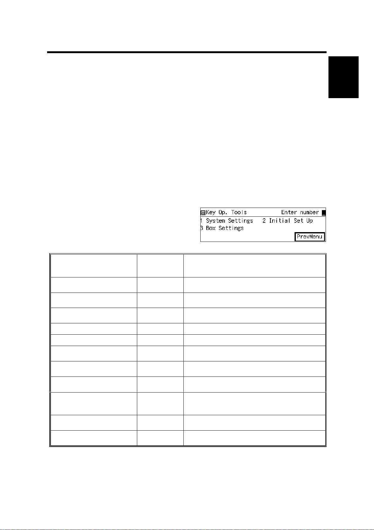
The following items can be programmed with “System Settings” in “Key Op. Tools.”
Make sure that the items are programmed correctly.
System Settings
Press
î
ë # then press ì .
Item
G3 number
G4 fax number
Polling ID
Confidential ID
Memory lock ID
RTI
TTI
G4_TID (Terminal ID)
CSI
(Used for G3 communication
only.)
IG3_CSI
(ISDN G3 CSI)
PSTN access code
:
H143M510.BMP
System
Setting
Function No.
16
16
15
15
15
11
11
14
12
13
12
Used for transfer operations in G3
communication.
Used for transfer operations in ISDN G4
communication.
Used for secured polling, transfer operations,
and closed network.
Used for confidential reception.
Used for memory lock.
Used to identify the terminal in G3 NSF/NSS
communications.
Printed on each transmitted page in G3
communications.
Used to identify the terminal in G4
communications.
Used to identify the terminal in G3 DIS/DCS
communications over PSTN.
Used to identify the terminal in G3
communications over an ISDN.
Used for G3 communication only.
Remarks
Installation
1-1

PROGRAMMING ITEMS 29 November, 1999
System
Item
G4 subscriber number - 1
(Own Fax Number)
G4 subscriber number - 2
(Own Fax Number)
G4 SPID number
G4 subaddress
ISDN G3 subscriber
number - 1
(Own Fax Number)
ISDN G3 subscriber
number - 2
(Own Fax Number)
ISDN G3 SPID number
ISDN G3 subaddress
Setting
Function No.
14
14
14
14
13
13
13
13
Remarks
Input a “-” (pause) after the area code.
When not using MSN* service:
Program the ISDN subscriber number here. If an
another terminal is on the same bus from the
DSU, identify the terminals using a sub-ad dr es s.
When using MSN* service:
Program the dedicated ISDN number for the
terminal as the 1st ISDN subscriber number. If
the customer wishes the machine to answer the
calls to a different number, program it as the 2nd
subscriber number.
This item is displayed only in the USA
models instead of subscriber number - 2
program menu. See the note.
Program the G4 SPID Number given when
connected under the US National ISDN.
Program a subaddress to identify the terminal, if
two or more terminals answer the call to the
subscriber number for G4 fax.
Input a “-” (pause) after the area code.
When not using MSN* service:
Program the ISDN subscriber number here. If an
another terminal is on the same bus from the
DSU, identify the terminals using a sub-ad dr es s.
When using MSN* service:
Program the dedicated ISDN number for the
terminal as the 1st ISDN subscriber number. If
the customer wishes the machine to answer the
calls to a different number, program it as the 2nd
subscriber number.
This item is displayed only in the USA
models instead of subscriber number - 2
program menu. See the note.
Program the ISDN G3 SPID Number given when
connected under the US National ISDN.
Program a subaddress to identify the terminal, if
two or more terminals answer the call to the
subscriber number for G3 fax.
* MSN: Multiple Subscriber Number. In this service, more than one number is
allocated to one line (one line can have up to 8 units connected to it).
Important:
Make sure that you input the following items when you connect the machine under
the US National ISDN network.
•
Subscriber number: G4 Subscriber Number (G4 Own Number)/ G3 Subscriber
Number (G3 Own Number)
•
SPID Number: G4 SPID/ G3 SPID
1-2

29 November, 1999 PROGRAMMING ITEMS
NOTE:
SPID (Service Profile Indication Number: G4 and I-G3) menu items are
displayed only in the USA models (default). SPID is used when the
machine is connected under the US National ISDN network.
If SPID is not used, or if the machine is not connected under the US
National ISDN network, please turn off with user parameter switch 06 bit 6.
This time, subscriber number - 2 program menus (G4 and I-G3) are
displayed instead.
1.2.2 SERVICE LEVEL PROGRAMMING
Item
System Swit ches
Communication Switches
G4 Internal Switches
Service
Function No.
01 - 0
01 - 3
17 - 0
System Switch 0A
- Default communication mode (bit 1)
- Network used for G3 transmission (bit 6)
- Network used for G4-to-G3 fallback (bit 7)
Communication Switch 07
- G4 to G3 fallback On/Off (bit 0)
- Fallback from G4 to G3 reflected in
Quick/Speed dials (bit 3)
Change the country code and reset the machine
first if necessary. Then change any of the locally
required settings.
Installation
Remarks
Settings become effective when you exit the service mode.
1.2.3 REMARKS AT INSTALLATION
Programming the Subscriber Numbers
When programming the subscriber numbers, input a “-” (pause) after the area
code. When the machine receives a call, it compares the digits after the last “-”
(pause) with the called number attached to the SETUP signal. The machine
responds to the call only when the numbers match.
For example:
If the subscriber number is programmed as, 123-456789,
the machine responds to the call only if the last 6 digits of the called number are
456789.
If the subscriber number is programmed as, 123-456-789,
the machine responds to the call only if the last 3 digits of the called number are
789.
NOTE:
Even if more than one “-” are programmed, the machine compares the
digits after the last “-.”
1-3
29 November, 1999 BLOCK DIAGRAM
2. OVERALL SYSTEM CONTROL
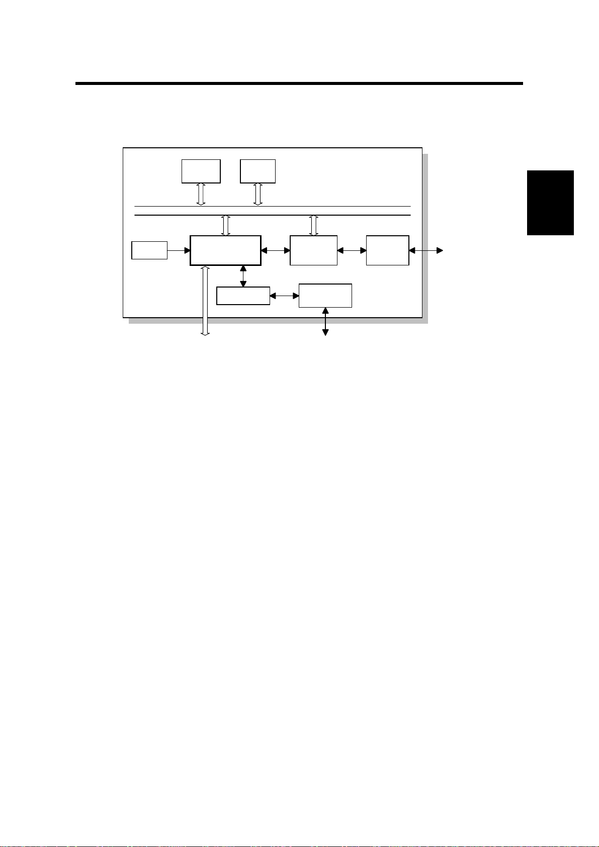
2.1 BLOCK DIAGRAM
Reset
Circuit
Flash
ROM
FCU
ICCP
CODEC
DRAM
SYSTEM BUS
Dch
Bch
LAPD
Controller
Analog I/F
Circuit
MODEM
SiG4 Board
ISDN
Interface
ISDN
H143D500.WMF
The SiG4 (Standard ISDN G4) board contains ICCP (ISDN Communication Control
Processor), Flash ROM, DRAM, LAPD controller, CODEC, ISDN interface and
analog interface. The ICCP controls the entire board.
ICCP
•
16 bit CPU which controls the entire board
•
HDLC con trol
•
Channel select for B channel interface control
Overall
Control
CODEC
•
A/D, D/A converter for ISDN G3 communication
LAPD Controller
•
ISDN layer 1 and LAPD control
ROM
•
512 kB (4 Mbit) Flash ROM for system software storage
DRAM
•
2MB (16 Mbit) DRAM used
The Flash ROM program can be updated using a flash memory card and the flash
memory copy tool.
Cross Reference
G4 Program Download: Section 4.1.20 and section 6.9.7 of the host machine’s
manual.
2-1
29 November, 1999 G4 SERVICE FUNCTIONS
3. SERVICE TABLES AND PROCEDURES
3.1 G4 SERVICE FUNCTIONS
î
ë
, then immediately ì ä ä å
4
within 3 seconds
H306M501.BMP
Press ì
NOTE:
æ
H143M500.BMP
Settings become effective when you exit the service mode.
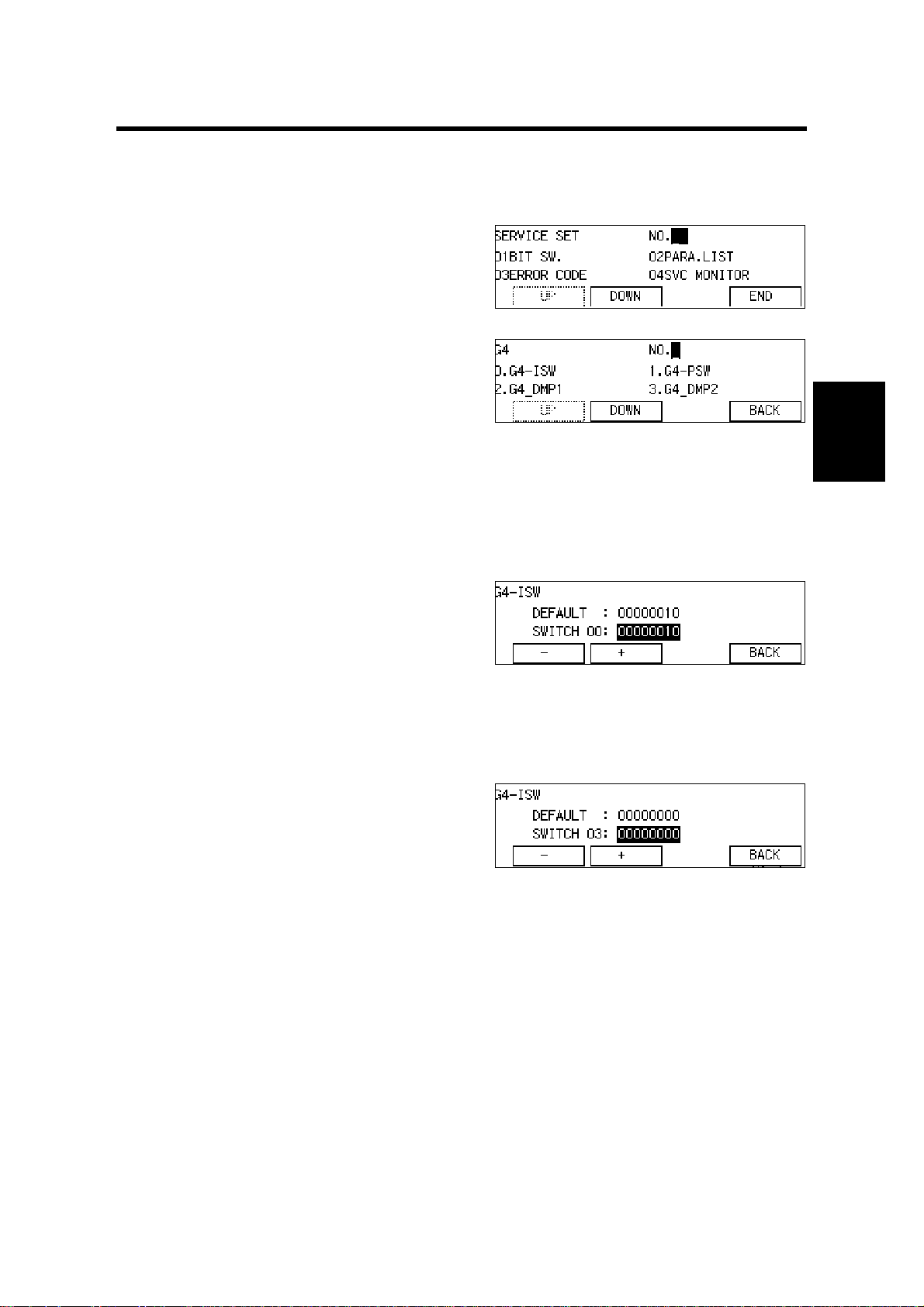
3.1.1 G4 INTERNAL SWITCH PROGRAMMING (FUNCTION 0)
1. After entering G4 service mode,
press í.
The default settings are shown on the
top line, and the current settings on the
bottom.
H143M501.BMP
Tables
Service
2. Increment bit switch: ò
Decrement bit switch:
ð
Example:
ò
Display bit switch 3: :
3 times
3. Adjust the bit switch.
To adjust more bit switches: go to step 2.
To finish: #
î
H143M502.BMP
3-1
G4 SERVICE FUNCTIONS 29 November, 1999
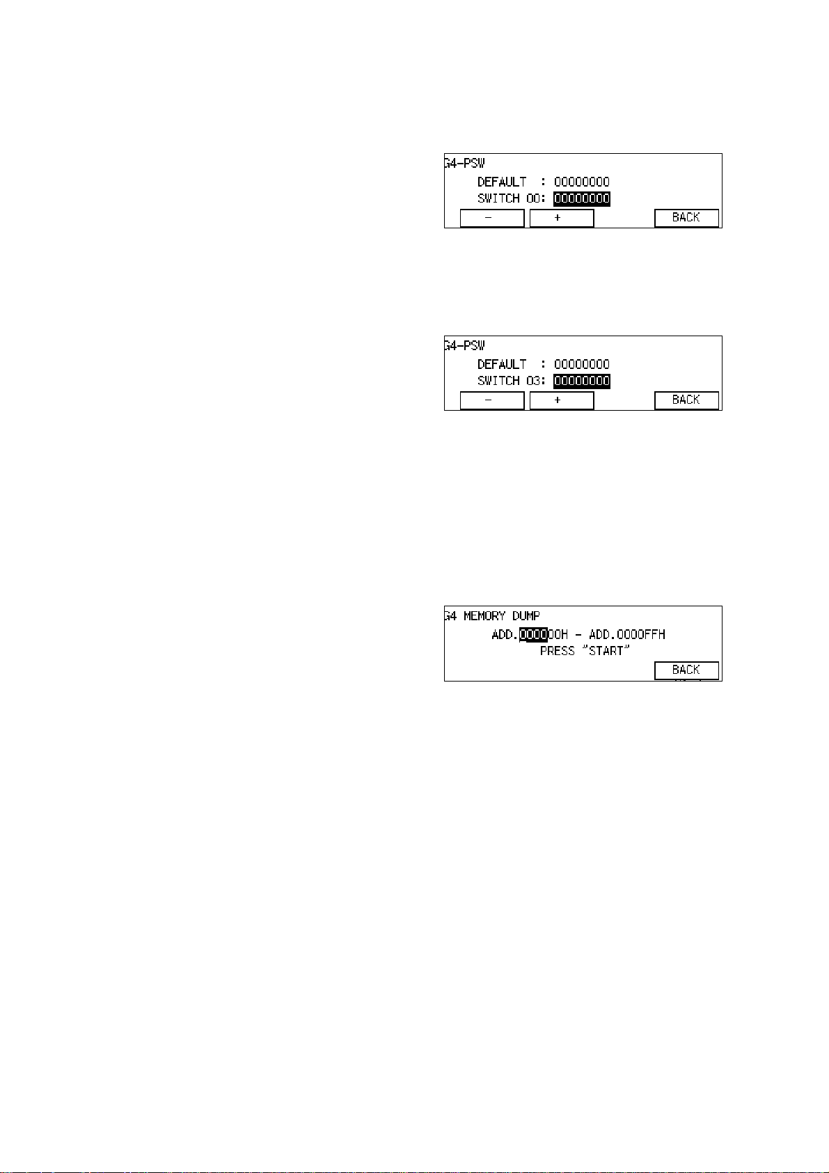
3.1.2 G4 PARAMETER SWITCH PROGRAMMING (FUNCTION 1)
1. After entering G4 service mode,
press ì .
The default settings are shown on the
top line, and the current settings on the
bottom.
2. Increment bit switch:
Decrement bit switch:
ò
ð
Example:
Display bit switch 3: ò 3 times
3. Adjust the bit switch.
To adjust more bit switches: go to step 2.
To finish: #
î
3.1.3 PRINTING G4 MEM ORY DUMP (FUNCTIO N 2)
Use this function to print the D-channel layer 1 dump list.
1. After entering G4 service mode,
press ë .
H143M504.BMP
H143M505.BMP
2. Input the range of addresses that you
wish to print.
Example:
Addresses 07EB00 to 07ECFF:
Input í æ ( % í æ ( & 4.
Layer 1 memory dump information is stored in the following addresses:
07EB00(H) to 07ECFF(H).
3-2
H143M507.BMP

29 November, 1999 G4 SERVICE FUNCTIONS
3.1.4 PRINTING G4 PROTOCOL DUMP LIST (FUNCTION 3)
1. From the G4 service mode menu,
press ê .
2. Either:
•
To print a protocol dump list for the
D channel and B channel 1: press
•
To print a protocol dump list for the D channel and B channel 2:
Then press
G4 Dump “D+BCH1”, “D+BCH2”:
Up to 2 kbytes data is stored. When the data exceeds this limit, it is
overwritten (The oldest data is overwritten first, also see G4 internal switch
03 bit 0).
D+BCH2 data is logged only when there is dual communication.
•
To print a protocol dump list for the D channel: ò x 2
Up to 2 kbytes data is stored.
•
To print a protocol dump list for the B channel 1 link layer: ò x 3
•
To print a protocol dump list for the B channel 2 link layer:
•
To print a protocol dump list for the D channel link layer:
4
4
3.1.5 MODEM/ DTMF TONE TESTS (FUNCTION 4)
4
ò
ò
x 5
x 4
4
ò
4
4
H143M508.BMP
Tables
Service
This is used only for PTT approval tests.
3.1.6 G4 SOFTWARE DOWNLOAD
The G4 software program can be updated using a flash memory card. Refer to the
host machine’s manual for details .
Cross Reference
G4 Program Download: Section 4.1.20 and section 6.9.7 of the host machine’s
manual.
3-3
 Loading...