

Page 1

ISDN Unit
(Machine Code: H143-20/21)
SERVICE MANUAL
June 4, 1999
Subject to change
Page 2

TABLE OF CONTENTS
1. INSTALLA T ION...........................................................................1-1
1.1 HARDWARE INSTALLATION .................................................................. 1-1
1.2 PROGRAMMING ITEMS.......................................................................... 1-1
1.2.1 USER LEVEL PROGRAMMING...................................................... 1-1
1.2.2 SERVICE LEVEL PROGRAMMING................................................ 1-3
1.2.3 REMARKS AT INSTALLATION....................................................... 1-3
2. OVERALL SYSTEM CONTROL..................................................2-1
2.1 BLOCK DIAGRAM.................................................................................... 2-1
3. SERVICE TABLES AND PROCEDURES................................... 3-1
3.1 SERVICE LEVEL FUNCTIONS................................................................ 3-1
3.1.1 G4 INTERNAL SWITCH PROGRAMMING (FUNCTION 0)............. 3-1
3.1.2 G4 PARAMETER SWITCH PROGRAMMING (FUNCTION 1)........ 3-2
3.1.3 PRINTING A G4 MEMORY DUMP (FUNCTION 2)......................... 3-2
3.1.4 PRINTING A G4 PROTOCOL DUMP LIST (FUNCTION 3)............. 3-3
3.1.5 MODEM/DTMF TONE TESTS (FUNCTION 4)................................ 3-3
3.1.6 G4 SOFTWARE DOWNLOAD......................................................... 3-3
3.1.7 BIT SWITCHES............................................................................... 3-4
3.1.8 G4 INTERNAL SWITCHES.............................................................. 3-4
3.1.9 G4 PARAMETER SWITCHES....................................................... 3-11
3.2 DEDICATED TRANSMISSION PARAMETERS*.................................... 3-14
4. TROUBLESHOOTING.................................................................4-1
4.1 ERROR CODES....................................................................................... 4-1
4.1.1 D-CHANNEL LAYER MANAGEMENT............................................. 4-2
4.1.2 D-CHANNEL, LAYER 1................................................................... 4-2
4.1.3 D-CHANNEL LINK LAYER.............................................................. 4-2
4.1.4 D-CHANNEL NETWORK LAYER.................................................... 4-3
4.1.5 B-CHANNEL LINK LAYER............................................................... 4-3
4.1.6 B-CHANNEL NETWORK LAYER.................................................... 4-4
4.1.7 TRANSPORT LAYER...................................................................... 4-4
4.1.8 SESSION LAYER............................................................................ 4-5
4.1.9 DOCUMENT LAYER ....................................................................... 4-6
4.1.10 PRESENTATION LAYER.............................................................. 4-6
4.2 LEDS........................................................................................................ 4-7
4.3 BACK-TO-BACK TEST............................................................................. 4-8
APPENDIX.......................................................................................A-1
USEFUL SWITCHES.......................................................................................A-1
i
Page 3

4 June, 1999 HARDWARE INSTALLATION
1. INSTALLATION
1.1 HARDWARE INSTALLATION
Install the hardware as described in Chapter 3 of the host fax machine's service
manual. Then program the following items.
NOTE:
1) Hardware installation is not required for the I-Schmidt 3 (H548 model).
2) When installing the ISDN G4 unit to the Schmidt 3 (H547 model), make
sure to set communication bit switch 16 bit 2 to “1.” Then turn the
machine off and on to enable the ISDN unit.
1.2 PROGRAMMING ITEMS
1.2.1 USER LEVEL PROGRAMMING
The following items can be programmed with user function 61 and 64. Make sure
that the items are programmed correctly.
Item
Own G3 number
Own G4 number
Polling ID
Confidential ID
Memory lock ID
RTI
TTI
G4_TID (Terminal ID)
CSI
(Used for G3 communication
only.)
IG3_CSI
(ISDN G3 CSI)
PSTN access code
Function
No.
User 61
User 61
User 61
User 61
User 61
User 61
User 61
User 61
User 61
User 61
User 61
Used for transfer operations in ISDN G3
communication.
Used for transfer operations in ISDN G4
communication.
Used for secured polling, transfer operations,
and closed network.
Used for confidential reception.
Used for memory lock.
Used to identify the terminal in G3 NSF/NSS
communications.
Printed on each transmitted page in G3
communications.
Used to identify the terminal in G4
communications.
Used to identify the terminal in G3 DIS/DCS
communications over PSTN
(cannot program in the I-Schmidt 3).
Used to identify the terminal in G3
communications over an ISDN.
Used for G3 communication only
(cannot program in the I-Schmidt 3).
Remarks
Installation
1-1
Page 4

PROGRAMMING ITEMS 4 June, 1999
G4 subscriber number - 1 User 64
G4 subscriber number - 2
User 64
G4 SPID number
User 64
G4 subaddress
User 64
ISDN G3 subscriber number - 1
ISDN G3 subscriber number - 2
ISDN G3 SPID number
ISDN G3 subaddress
User 64
User 64
User 64
User 64
Input a “-“ (pause) after the area code.
When not using MSN* service:
Program the ISDN subscriber number here. If an
another terminal is on the same bus from the
DSU, identify the terminals using a sub-ad dr es s.
When using MSN* service:
Program the dedicated ISDN number for the
terminal as the 1st ISDN subscriber number. If
the customer wishes the machine to answer the
calls to a different number, program it as the 2nd
subscriber number.
This item is displayed only in the USA
models.
Program the G4 SPID Number given when
connected under the US National ISDN.
Program a subaddress to identify the terminal, if
two or more terminals answer the call to the
subscriber number for G4 fax.
Input a “-“ (pause) after the area code.
When not using MSN* service:
Program the ISDN subscriber number here. If an
another terminal is on the same bus from the
DSU, identify the terminals using a sub-ad dr es s.
When using MSN* service:
Program the dedicated ISDN number for the
terminal as the 1st ISDN subscriber number. If
the customer wishes the machine to answer the
calls to a different number, program it as the 2nd
subscriber number.
This item is displayed only in the USA
models.
Program the ISDN G3 SPID Number given when
connected under the US National ISDN.
Program a subaddress to identify the terminal, if
two or more terminals answer the call to the
subscriber number for G3 fax.
* MSN: Multiple Subscriber Number. In this service, more than one number is
allocated to one line (one line can have up to 8 units connected to it).
NOTE:
1) Subscriber numbers are indicated as “SN” on the display in Europe and
Asia models, whereas they are indicated as “DN” (directory number) in
the USA models.
2) SPID (Service Profile Indication Number: G4 and I-G3) menu items are
displayed only in the USA models (default). However, they can be
turned off with user parameter switch 06 bit 6. This time, subscriber
number - 2 program menus (G4 and I-G3) are displayed instead.
1-2
Page 5

4 June, 1999 PROGRAMMING ITEMS
1.2.2 SERVICE LEVEL PROGRAMMING
Item Function No. Remarks
System Swit ches
Communication Switches
G4 Internal Switches
NOTE:
Settings become effective when you exit the service mode.
01 - 0
01 - 4
16 - 01
System Switch 0A
- Default communication mode (bit 1)
- Network used for G3 transmission (bit 6)
(not required for the I-Schmidt 3)
- Network used for G4-to-G3 fallback (bit 7)
(not required for the I-Schmidt 3)
Communication Switch 07
- G4 to G3 fallback On/Off (bit 0)
- Fallback from G4 to G3 reflected in
Quick/Speed dials (bit 3)
Change the country code and reset the machine
first if necessary. Then change any of the locally
required settings and/or the following.
Internal Switch 13
- Condition for fallback from G4 to G3
Internal Switches 17, 18, 1A, 1B and 1C
- G4 to G3 automatic fallback parameters
1.2.3 REMARKS AT INSTALLATION
Programming the Subscriber Numbers
Installation
When programming the subscriber numbers, input a “-“ (pause) after the area
code. When the machine receives a call, it compares the digits after the last “-“
(pause) with the called number attached to the SETUP signal. The machine
responds to the call only when the numbers match.
For example:
If the subscriber number is programmed as, 123-456789,
the machine responds to the call only if the last 6 digits of the called number are
456789.
If the subscriber number is programmed as, 123-456-789,
the machine responds to the call only if the last 3 digits of the called number are
789.
NOTE:
Even if more than one “-“ are programmed, the machine compares the
digits after the last “-.”
1-3
Page 6

PROGRAMMING ITEMS 4 June, 1999
G4 to G3 Fallback
To ensure G4 to G3 fallback occurs for almost all cases, the following switches
should be programmed at installation.
G4 internal switch 13 bit 7
: Fallback in response to any CPS code (G4 internal switches 17, 18, 1A, 1B, and
1
: Condition for fallback from G4 to G3
1C do not have to be programmed.)
Communication switch 07 bit 3
: Fallback from G4 to G3 reflected in programmed
Quick/Speed Dials
: Always start to transmit with G4
1
1-4
Page 7
4 June, 1999 BLOCK DIAGRAM
2. OVERALL SYSTEM CONTROL
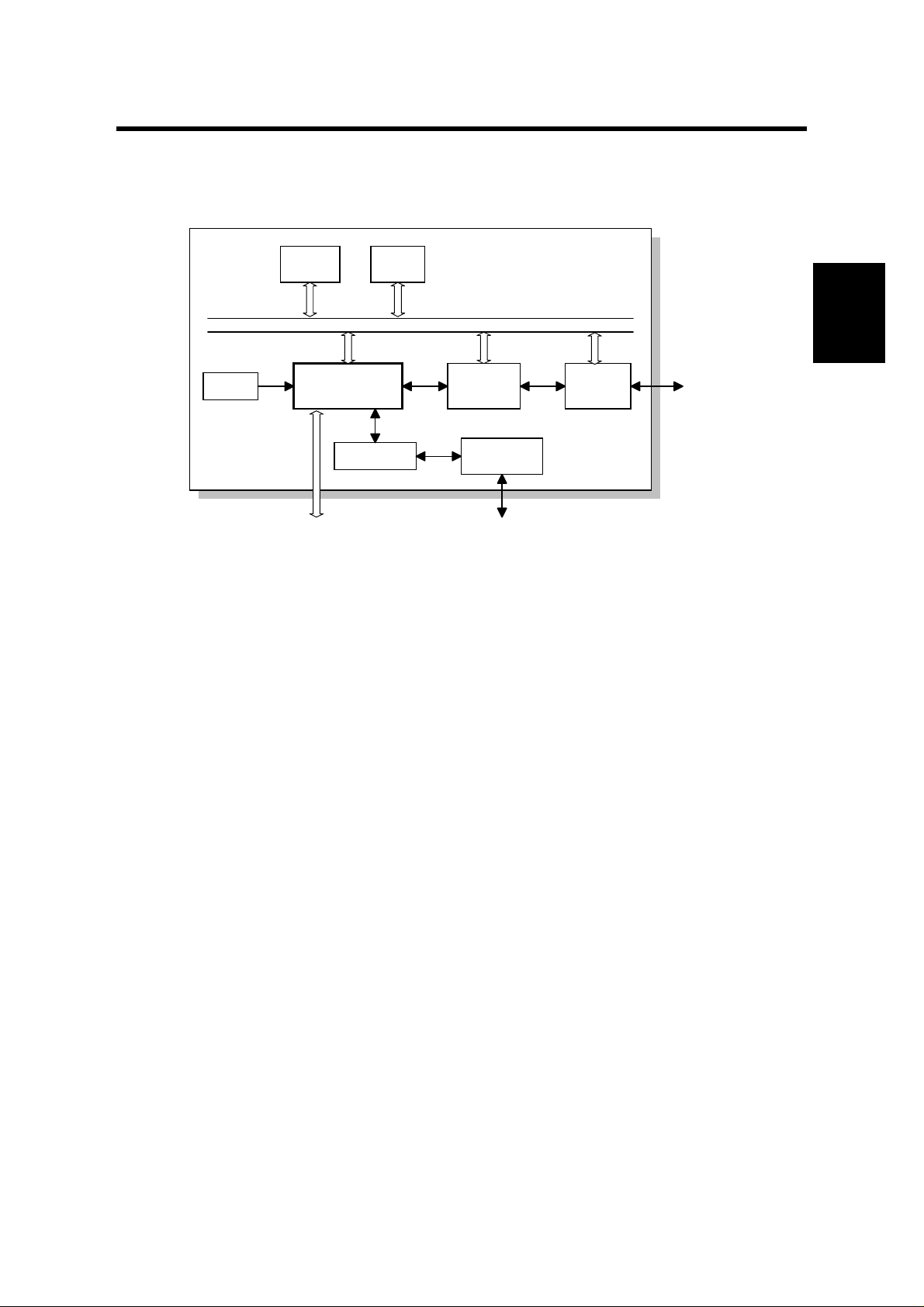
2.1 BLOCK DIAGRAM
Reset
Circuit
Flash
ROM
FCU
ICCP
CODEC
DRAM
SYSTEM BUS
Dch
Bch
LAPD
Controller
Analog I/F
Circuit
MODEM
SiG4
ISDN
Interface
ISDN
H548D500.WMF
The SiG4 (Standard ISDN G4) board contains ICCP (ISDN Communication Control
Processor), Flash ROM, DRAM, LAPD controller, CODEC, ISDN interface and
analog interface. The ICCP controls the entire board.
ICCP
•
16 bit CPU which controls the entire board
•
HDLC con trol
•
Channel select for B channel interface control
Overall
Control
CODEC
•
A/D, D/A converter for ISDN G3 communication
LAPD Controller
•
ISDN layer 1 and LAPD control
ROM
•
512 kB (4 Mbit) Flash ROM for system software storage
DRAM
•
2MB (16 Mbit) DRAM used
The Flash ROM program can be updated using a flash memory card and the flash
memory copy tool.
2-1
Page 8

4 June, 1999 SERVICE LEVEL FUNCTIONS
3. SERVICE TABLES AND PROCEDURES
3.1 SERVICE LEVEL FUNCTIONS
To enter G4 service mode, press the following sequence of keys:
òñ
ç ì ä ä
å
then immediately ú .
FUNCTION KPAD/NEXT>
■■SERVICE FUNCTIONS
Press
NOTE:
then
ú
.
ì ç
Settings become effective when you exit the service mode.
0-G4_ISW 1-G4_PSW
2-G4_DMP1 3-G4_DMP2
3.1.1 G4 INTERNAL SWITCH PROGRAMMING (FUNCTION 0)
1. After entering G4 service mode,
press í.
Bit 7 is displayed at the left, and bit 0 at the right. The default settings are
shown on the top line, and the current settings on the bottom.
õ
ö
x 3
2. Increment bit switch: õ
Decrement bit switch:
Example:
Display bit switch 3:
ISW DF 0001 0001
BITSW 00: 0001 0001
ISW DF 0000 0000
BITSW 03: 0000 0000
Tables
Service
3. Adjust the bit switch.
Example: To change the value of bit 7, press æ .
4. Either:
•
Adjust more bit switches - go to step 2.
•
Finish -
ú
3-1
ISW DF 0000 0000
BITSW 03: 1000 0000
Page 9

SERVICE LEVEL FUNCTIONS 4 June, 1999
3.1.2 G4 PARAMETER SWITCH PROGRAMMING (FUNCTION 1)
1. After entering G4 service mode,
press ì .
Bit 7 is displayed at the left, and bit 0 at the right. The default settings are
shown on the top line, and the current settings on the bottom.
2. Increment bit switch:
Decrement bit switch:
Example:
Display bit switch 3: õ x 3
3. Adjust the bit switch.
Example: To change the value of
bit 7, press æ .
4. Either:
•
Adjust more bit switches - go to step 2.
•
Finish -
ú
õ
ö
PSW DF 0000 0000
BITSW 00: 0000 0000
PSW DF 0000 0000
BITSW 03: 0000 0000
PSW DF 0000 0000
BITSW 03: 1000 0000
3.1.3 PRINTING A G4 MEMORY DUMP (FUNCTION 2)
Use this function to print the D-ch. Layer 1 dump list.
1. After entering G4 service mode,
press ë .
2. Input the range of addresses that you wish to print.
Example:
Input í æ ( % í æ ( & ÷.
Addresses 07EB00 to 07ECFF:
G4_DMP1 START/N
ADD.000000 - 0000FF
3-2
Page 10

4 June, 1999 SERVICE LEVEL FUNCTIONS
3.1.4 PRINTING A G4 PROTOCOL DUMP LIST (FUNCTION 3)
1. From the G4 service mode menu,
press ê .
2. Either:
•
Print a protocol dump list for the D channel and B channel 1:
•
Print a protocol dump list for the D channel and B channel 2:
D+BCH1/D+BCH2:
Up to 2 kbytes data is stored. When the data exceeds this limit, it is
overwritten (The oldest data is overwritten first, also see G4 internal switch
03 bit 0.)
D+BCH2 data is logged only when there is dual communication.
•
Print a protocol dump list for the D channel: õ x 2
Up to 2 kbytes data is stored.
•
Print a protocol dump list for the B channel 1 link layer: õ x 3
•
Print a protocol dump list for the B channel 2 link layer:
•
Print a protocol dump list for the D channel link layer:
3. Reset parameter switch E bit 0 to 0 after you have finished.
G4_DMP2 Y/<>
CODE0 D+BCH1
÷
õ
õ
x 4
x 5
÷
õ ÷
÷
÷
÷
Tables
Service
3.1.5 MODEM/ DTMF TONE TESTS (FUNCTION 4)
This is only for use during PTT approval tests.
3.1.6 G4 SOFTWARE DOWNLOAD
The G4 software program can be updated using a flash memory card and the flash
memory copy tool. Refer to section 4.1.27 of the mainframe service manual.
3-3
Page 11

SERVICE LEVEL FUNCTIONS 4 June, 1999
3.1.7 BIT SWITCHES
ø
WARNING
Do not adjust a bit switch that is described as "Not used", as this may
cause the machine to malfunction or to operate in a manner that is not
accepted by local regulations.
NOTE:
Settings become effective when you exit the service mode.
3.1.8 G4 INTERNAL SWITCHES
Bit Switch 00
FUNCTION COMMENTS
Country code
0
Bit 4 3 2 1 0 Country
to
0 0 0 0 1 Germany (1TR6 mode)
7
0 0 0 1 0 Universal (Europe Euro ISDN)
1 0 0 0 1 USA
Note: In Germany, use the Universal setting for the Euro ISDN lines.
Bit switches 01 and 02 are not used. Do not change the settings.
Bit Switch 03
FUNCTION COMMENTS
Amount of protocol dump data
in one protocol dump list
0: Last communication only
0
1: Up to the limit of the
memory area for protocol
dumping
1-7
Not used Do not change the settings.
Change this bit to 0 if you want to have a
protocol dump list of the last communication
only.
This bit is only effective for the dump list D +
Bch1.
Bit Switch 04
0-2
Not used Do not change the settings.
Auto data rate change for
transmission
(64 kbps to 56 kbps)
3
0: On
1: Off
Auto data rate change for
reception (64 kbps to 56 kbps)
0: Off
4
1: On
5-7
Not used Do not change the settings.
FUNCTION COMMENTS
0: The machine automatically changes the
transmission data rate from 64 kbps to 56 kbps
after 3 s if the other end did not accept the call.
This is to cope with 56 kbps networks in the
USA.
Normally, keep this bit at 0.
1: The machine automatically changes the
reception data after 6 s.
Change this bit to 1 only when there is a
communication error where the other terminal
informs 64 kbps in the SETUP signal although it
is actually 56 kbps.
3-4
Page 12

4 June, 1999 SERVICE LEVEL FUNCTIONS
Bit Switch 05
FUNCTION COMMENTS
0-1
Not used Do not change the settings.
Protocol ID check
2
0: Yes 1: No
3-7
Not used Do not change the settings.
The Protocol ID is in the CR packet.
Bit switches 06 to 0F are not used. Do not change the settings.
Bit Switch 10 (Dch. Layer 1)
FUNCTION COMMENTS
0-5
Not used Do not change the settings.
INFO1 signal resend
0: Resend
6
1: No resend
7
Not used Do not change the settings.
0: Some DSUs may not reply to the INFO1
signal with INFO2, if there is noise in the INFO1
signal accidentally. Try changing this bit to 0, to
resend INFO1 before the machine displays
“CHECK INTERFACE”.
Tables
Service
Bit Switch 11 (Dch. Layer 2)
FUNCTION COMMENTS
0
Not used Do not change the settings.
Type of TEI used
0: Dynamic TEI
1
1: Static TEI
This is normally fixed at 0. However, some
networks may require this bit to be set at 1 (see
below). In this case, you may have to change
the values of bits 2 to 7.
Static TEI value
2
to
7
Store the lowest bit of the TEI at bit 7 and the
highest bit of the TEI at bit 2.
Example: If the static TEI is 011000, set bits 3
and 4 to 1 and bits 2, 5, 6, and 7 to 0.
Bit switch 12 is not used. Do not change the settings.
3-5
Page 13

SERVICE LEVEL FUNCTIONS 4 June, 1999
Bit Switch 13: D channel layer 3 (Attachment IE in S: SETUP)
FUNCTION COMMENTS
0-1
Not used Do not change the settings.
Attachment of calling ID
0: No 1: Yes
2
Normally, this bit should be at 0, because most
networks add the calling ID to the SETUP
signal to the receiver.
However, some networks may require the
machine to add this ID. Only in this case
should this bit be at 1.
Attachment of the Lower Layer
Capabilities
3
0: No 1: Yes
This bit determines whether Lower Layer
Capabilities are informed in the [SETUP]
signal.
Keep this bit at 0 in most cases.
Attachment of the Higher Layer
Capabilities
4
0: Yes 1: No
This bit determines whether Higher Layer
Capabilities are informed in the [SETUP] signal
or not.
Keep this bit at 0 in most cases.
Attachment of the channel
5
information element (CONN)
Keep this bit at 0 in most cases.
0: No 1: Yes
Attachment of the Higher Layer
Capabilities for ISDN G3
transmission
0: Same as the bit 4 setting
6
1: Not attached
This bit determines whether Higher Layer
Capabilities are informed in the [SETUP] signal
for ISDN G3 transmission. This switch is
effective in coping with communication
problems with some types of T/A and PBX
which do not respond to Higher Layer
Capability “G3.”
When this bit is set to 0, the setting depends on
the setting of bit 4.
Condition for fallback from G4 to
G3
0: Refer to the CPS code setting
1: Fallback in response to any
CPS code
7
0: Fallback occurs when a CPS code is the
same as the CPS code settings specified by
G4 internal switches 17, 18, 1A, 1B, and 1C.
If you wish to enable fallback when any CPS
code is detected, set this bit to “1.”
This switch is effective in coping with fallback
problems where the CPS code does not match
those specified in the ITU-T recommendation
Q.931.
3-6
Page 14

4 June, 1999 SERVICE LEVEL FUNCTIONS
Bit Switch 14: D channel layer 3 (Selection IE in S: SETUP)
FUNCTION COMMENTS
ISDN G3 information transfer
capability
0: 3.1 kHz audio
1: Speech
0
In tx mode, this determines the information
transfer capability informed in the [SETUP]
message.
In rx mode, this determines the information
transfer capability that the machine can use to
receive a call.
Set this bit to 1 if the ISDN does not support
3.1 kHz audio.
1-2
Not used Do not change the settings.
Channel selection in [SETUP] in
tx mode
3
Bit 4 3 Setting
Any channel: When this is informed to the
exchanger, the exchanger will select either B1
or B2.
0 0 Any channel
4
0 1 B1 channel
1 0 B2 channel
1 1 Not used
Called ID mapping
0: Called party number
5
1: Keypad facility
0: Called ID is mapped to the called party
number.
1: Called ID is mapped to the keypad facility.
On the 5ESS network (USA), set it to 1.
Numbering plan for the called
party number
6
0: Unknown
1: E.164
Subaddress coding type
7
0: IA5 (NSAP)
E.164: This may be used in Sweden if an
AXE10 exchanger is fitted with old software,
and in Australia.
Unknown: This is the normal setting.
This is normally kept at 0. However, some
networks require this bit to be at 1.
1: BCD (ISO8348)
Tables
Service
Bit Switch 15: D channel layer 3 (Judgement R: MSG)
FUNCTION COMMENTS
Action when receiving [SETUP]
signal containing no called
subaddress, if the subaddress
0
was programmed in the dialed
This bit depends on user requirements. If it is
at 1, communication will be halted if the other
terminal has not input the subaddress.
number
0: A reply is sent
1: No reply is sent
1-4
Not used Do not change the settings
Global call reference
0: Ignored
5
1: Global call number is used
Global call reference means 'call reference
value = 0'. This bit determines how to deal with
such an incoming call if received from the
network.
Keep this bit at 1 in Germany 1TR6.
6-7
Not used Do not change the settings.
3-7
Page 15

SERVICE LEVEL FUNCTIONS 4 June, 1999
Bit Switch 16: D channel layer 3 (Approval)
FUNCTION COMMENTS
Answer delay time
Bit 1 0 Setting
0 0 No delay
0 1 1.0 s delayed (1TR6)
1 0 0.5 s delayed
1 1 Not used
0
1
In Germany 1TR6, a time delay to answer a
call is required.
In other countries, use this switch as follows:
If the machine is connected to the same bus
from the DSU as a model K200 is connected,
the machine receives most of the calls because
the response time to a call is faster than the
K200.
If the customer wants the K200 to receive most
of the calls, adjust the response time using
these bits.
If the customer does not want one machine to
receive most of the calls, use subaddresses to
identify each terminal.
Action when receiving
[SETUP] signal containing
user-specific callrd party
subaddress
0: Ignores the call
2
1: Receives the call
Normally, the 3rd octet of called party
subaddress information in the [SETUP] signal
is set to NSAP. However, some networks may
add “user-specific” subaddress to the [SETUP]
signal, and the result of this is that the machine
won't answer the call if a subaddress is
specified.
So, change this bit to 1 to let the machine
receive the call if the machine is connected to
such a network.
3-4
Not used Do not change the settings.
Indicated bearer capabilities
0: 56 kbps 1: 64 kbps
5
1: 64 kbps calling is indicated in the Bearer
Capabilities, but communication is at 56 k. Use
this bit if the machine is connected to a network
which does not accept a 56 kbps data transfer
rate as a bearer capability.
6
Not used Do not change the settings.
Transfer capabilities (SI)
informed in 1TR6 ISDN G3
transmission
7
0: G3 Fax
1: Analog
This bit determines whether transfer
capabilities informed in the Service Indicator for
1TR6 ISDN G3 transmission. This switch is
effective in coping with communication
problems with some types of T/A and PBXs.
3-8
Page 16

4 June, 1999 SERVICE LEVEL FUNCTIONS
Bit Switch 17: CPS Code Used for G4 to G3 Fallback - 1
FUNCTION COMMENTS
Condition for fallback from G4 to G3
Bits 0 to 6 of bit switch 17 contain a CPS code, and bits 0 to 6 of bit switch 18
contain another CPS code. If a CPS code is received which is the same as either
of these, communication will fall back from ISDN G4 mode to ISDN G3 mode.
The CPS codes must be the same as those specified in table 4-13 of CCITT
0
to
recommendation Q.931.
Examples: Bit 6 5 4 3 2 1 0
6
For the codes in bits 0 to 6 of bit switches 17 and 18 to be recognized, bit 7 of bit
switch 17 must be 1. Also, bit 0 of the Communication Switch 07 must be at 0, or
Fallback from G4 to G3 will be disabled.
This bit determines whether fallback from G4 to G3 occurs on receipt of one of
the CPS codes programmed in bit switch 17 or 18, or on receipt of a certain
standard code.
0: Fallback occurs on receipt of any of the following CPS codes:
7
Universal (Euro ISDN) - #3, #18, #57, #58, # 63, # 65, #79, #88, and #127
Germany 1TR6 mode - #3, #53, #58, and #90
Others - #3, #65, and #88
1: Fallback from G4 to G3 occurs on receipt any of above CPS codes or one of
the CPS codes programmed in bit switch 17, 18, 1A, 1B, or 1C
1 0 0 0 0 0 1 CPS code 65
1 0 1 1 0 0 0 CPS code 88
Tables
Service
Bit Switch 18: CPS Code Used for G4 to G3 Fallback - 2
FUNCTION COMMENTS
0
Condition for fallback from G4 to G3
to
See the explanation for bits 0 to 6 of bit switch 17
6
This bit helps to choose the CPS code se t for G4 to G3 fallback.
0: Fallback occurs on receipt of the CPS code set which is specified by the
country code setting.
1: Fallback occurs on receipt of the Universal CPS code set (#3, #18, #57, #58,
7
# 63, # 65, #79, #88, and #127) even if another country code is programmed.
If bit switch 17 bit 7 is “1”, fallback occurs on receipt of the Universal CPS code
set or one of the CPS codes programmed in bit switches 17, 18, 1A, 1B, or 1C.
G4 to G3 fallback
Bit 0 of Communication Switch 07 must be at 0, or fallback from G4 to G3 will be
disabled.
The CPS codes for which fallback occurs are decided as follows.
•
G4 bit switch 17, bit 7 - If set to “0”, fallback occurs on receipt of a code from a
set that depends on the country code. If set to ”1”, fallback occurs for the 5 CPS
codes programmed in bits 0 to 6 of G4 bit switches 17, 18, 1A, 1B, and 1C, in
addition to the country code set.
Note that if G4 bit switch 18, bit 7 is set to “1”, the CPS code set that is used is
always the Universal set, regardless of the country code setting.
3-9
Page 17

SERVICE LEVEL FUNCTIONS 4 June, 1999
Bit Switch 19
FUNCTION COMMENTS
Permanence of the link
0: Set/released each
0
LAPD call
1: Permanent
Channel used in ISDN
1
L2 (64k) mode
0: B1 1: B2
2-7
Bit Switch 1A: CPS Code Used for G4 to G3 Fallback - 3
to
Not used Do not change the factory settings.
FUNCTION COMMENTS
0
Condition for fallback from G4 to G3
See the explanation for bits 0 to 6 of bit switch 17.
6
7
Not used Do not change the setting.
Keep this at 1 in the USA. In other areas, this bit is
normally 0, depending on network requirements.
When making an IDSN L2 back-to-back test, you can
select either the B1 or B2 channel with this bit switch.
Bit Switch 1B: CPS Code Used for G4 to G3 Fallback - 4
FUNCTION COMMENTS
0
Condition for fallback from G4 to G3
to
Bit Switch 1C: CPS Code Used for G4 to G3 Fallback - 5
to
See the explanation for bits 0 to 6 of bit switch 17
6
7
Not used. Do not change the setting.
FUNCTION COMMENTS
0
Condition for fallback from G4 to G3
See the explanation for bits 0 to 6 of bit switch 17
6
7
Not used. Do not change the setting.
Bit switches 1D to 1F are not used. Do not change any of the settings.
3-10
Page 18

4 June, 1999 SERVICE LEVEL FUNCTIONS
3.1.9 G4 PARAMETER SWITCHES
Parameter Switch 00
FUNCTION COMMENTS
0
Network type
Bit 2 1 0 Type
1
x 0 0 Circuit sw itched ISDN
Other settings: Not used
2
3-7
Parameter Switch 01
2-6
Not used Do not change the default settings.
FUNCTION COMMENTS
Voice coding
0
0: µ law
1: A law
Action when [SETUP]
signal without HLC is
received
1
0: Respond to the call
1: Not respond to the
call
Not used Do not change the settings.
Signal attenuation for
G3 fax signals received
from ISDN line (-6dB)
7
0: Off 1: On
0: This setting is used in USA.
1: This setting is used in Europe and Asia.
If there are several TEs on the same bus and the
machine responds to calls for another TE, the call may
be without HLC information.
Identify the type of calling terminal and change this bit
to 1 if the caller is not a fax machine.
0: If an analog signal comes over digital line, the
signal level after decoding by the TE is theoretically
the same as the level at the entrance to the digital line.
However, this sometimes causes the received signal
level to be too high at the received end. In this case,
set this bit to 1 to adjust the attenuation level.
Do not change the default setting.
Tables
Service
Parameter Switch 02
FUNCTION COMMENTS
0
1
2-7
Data rate (kbps)
Bit 1 0 Setting
0 0 64 kbps
0 1 56 kbps
Not used Do not change the settings.
Other settings: Not used
Parameter Switch 03 and 04 are not used. Do not change any of the settings.
Parameter Switch 05
FUNCTION COMMENTS
0-3
5-7
Not used Do not change the settings.
B-channel T3 timer
0: 30s
4
1: 57s
Not used Do not change the settings.
1: This switch is useful when used in combination with
the Communication Bit SW 07 bit 4. This is to cope
with communication problems where G4
communication fails on the ISDN B-channel.
3-11
Page 19

SERVICE LEVEL FUNCTIONS 4 June, 1999
Parameter Switch 06
FUNCTION COMMENTS
Layer 3 protocol
0: ISO8208
0
1: T.70NULL
1-7
Parameter Switch 07
4-7
Not used Do not change the settings.
FUNCTION COMMENTS
Packet size
0
Bit 3 2 1 0 Value
0 1 1 1 128
1
1 0 0 0 256
1 0 0 1 512
2
1 0 1 0 1024
1 0 1 1 2048
3
Not used Do not change the settings.
Set this bit to match the type of layer 3 signalling used
by the ISDN.
The dedicated parameters have the same setting for
specific destinations.
This value is sent in the CR packet. This value must
match the value stored in the other terminal, or
communication will stop (CI will be returned). If the
other end returns CI, check the value of the packet
window size with the other party.
Note that this value must be the same as the value
programmed for the transport block size (G4
Parameter Switch 0B, bits 0 to 3).
Normally, do not change the default setting.
Parameter Switch 08
FUNCTION COMMENTS
0
1
2
3
4-7
Packet window size
Bit 3 2 1 0 Value
0 0 0 1 1
0 0 1 0 2
and so on until
1 1 1 1 15
Not used Do not change the settings.
This is the maximum number of unacknowledged
packets that the machine can send out before having
to pause and wait for an acknowledgement from the
other end.
Normally this should be kept at 7.
Parameter Switch 09 and 0A are not used. Do not change any of the settings.
Parameter Switch 0B
FUNCTION COMMENTS
0
1
2
3
4-7
Transport block size
Bit 3 2 1 0 Value
0 1 1 1 128
1 0 0 0 256
1 0 0 1 512
1 0 1 0 1024
1 0 1 1 2048
Not used Do not change the settings.
This value must match the value set in the other
terminal. Note that this value must be the same as the
value programmed for the packet size (G4 Parameter
Switch 7, bits 0 to 3). Also, the transport block size is
limited by the amount of memory in the remote
terminal.
Parameter Switch 0C is not used. Do not change any of the settings.
3-12
Page 20

4 June, 1999 SERVICE LEVEL FUNCTIONS
Parameter Switch 0D
FUNCTION COMMENTS
Back-to-back test mode
Bit 1 0 Setting
0 0 Off
1 0 ISDN L2 test mode (TE mode)
0
Other settings - Not used
When doing a back-to-back test or
doing a demonstration without a
line simulator, use these bits to set
up one of the machines in TE
mode, and the other in NT mode
Please note that this machine can
1
only be set to TE mode.
After the test, return both bits to 0.
See "Back-to-back Testing" in the
Troubleshooting section for full
details.
2-7
Not used Do not change the settings.
Parameter Switch 0E and 0F are not used. Do not change any of the settings.
Tables
Service
3-13
Page 21

DEDICATED TRANSMISSION PARAMETERS* 4 June, 1999
3.2 DEDICATED TRANSMISSION PARAMETERS*
The following G4 communication parameter bytes have been added for each Quick
Dial and Speed Dial. For how to program Dedicated Transmission Parameters,
refer to the Service Manual for the base machine.
Switches 01 to 04 are for use with Group 3 communication and are explained in
the Service Manual for the base machine.
Switches 05 to 08are not used. Do not change the settings.
Switch 09
FUNCTION
Layer 3 protocol Bit 3 2 1 0 Setting
0
1
2
3
4-7
0 0 0 0 IS.8208
0 0 0 1 T.70 NULL
1 1 1 1 As in Paramet er Switch 6, bit 0
Other settings: Not used
Not used
Switch 10 (Optional ISDN G4 unit required)
FUNCTION COMMENTS
0
Attachment of the Higher Layer
Capabilities
0: Yes 1: No
1
Not used Do not change the settings.
2
ISDN G3 information transfer
capability for transmission
0: 3.1 kHz audio
1: Speech
3-7
Not used Do not change the settings.
This bit determines whether Higher Layer
Capabilities are informed in the [SETUP]
signal.
This determines the information transfer
capability informed in the [SETUP]
message. Set this bit to 1 if the ISDN
does not support 3.1 kHz audio.
3-14
Page 22

4 June 1999 ERROR CODES
4. TROUBLESHOOTING
4.1 ERROR CODES
The tables on the following pages show the error codes that will be printed on the
Service Monitor Report. See the Service Manual for the base machine for
instructions on how to print this report.
The meaning of the numbers in the Action column is as follows.
1. Check Layer 1 signaling with a protocol analyzer to determine the cause of the
problem. This may require assistance from a G4 specialist.
2. Repeat the communication. If the problem does not repeat itself, the problem
was a temporary one caused by the user connecting the machine to another
interface. However, if the problem remains, there is a network problem.
3. There is a network problem.
4. There is a network problem. Do the following:
•
Check the error bit rate of the network. If it is high, contact the network and
ask them to improve the line.
•
Check the network speed (is it 56 or 64 kbps), and make sure that the bit
switch setting is correct. You may also use the dedicated transmission
parameters if this problem only occurs when dialling certain numbers.
•
Check that the user dialled the correct number.
Trouble-
shooting
5. There is a network problem, or a problem in the machine at the other end.
6. There is a problem in the machine at the other end; ask a technician to check it.
7. The machine at the other end is not a Group 4 fax terminal.
8. The machine is not compatible with the machine at the other end. A
compatibility test is needed.
Error codes related with the errors detected by the FCU are listed in the Service
Manual of the main body.
4-1
Page 23

ERROR CODES 4 June 1999
4.1.1 D-CHANNEL LAYER MANAGEMENT
Code Probable Cause Action
7-00 Link reset 2
7-01 Link set-up failed because of time-out. 2
7-02 Link release failed because of time-out. 2
7-03 Link set-up parameter error 2
4.1.2 D-CHANNEL, LAYER 1
Code Probable Cause Action
7-10 T3 timeout (layer 1 activation error) 1
7-11 No connection on the S0 interface 1
7-12 Deactivated 1
4.1.3 D-CHANNEL LINK LAYER
Code Probable Cause Action
7-20 At the start of link set-up, the machine received an unsolicited S
(F=1).
7-21 At the start of link set-up, the machine received an unsolicited DM
(F=1).
7-22 At TEI release, the machine received an unsolicited UA (F=1). 2
7-23 At the start of link set-up, the machine received an unsolicited DM
(F=0).
7-24 At TEI release, the machine received an unsolicited UA (F=0). 2
7-25 SABME received at the start of network link set-up
7-26 N200 retransmission error for SABME 2
7-27 N200 retransmission error for DISC 2
7-28 N200 retransmission error for situation enquiry (RR) 2
7-29 N(R) sequence number error 3
7-30 N(S) sequence number error 3
7-31 FRMR received 3
7-32 Non-standard frame received 3
7-33 Abnormal frame length 3
7-34 N201 error; information field N in the I frame exceeded N201 3
7-35 T201 timeout; timeout while waiting for checking 3
7-36 T202 timeout; timeout while waiting for ID assignment 3
2
2
2
No
error
4-2
Page 24

4 June 1999 ERROR CODES
4.1.4 D-CHANNEL NETWORK LAYER
Code Probable Cause Action
7-40 Insufficient mandatory information elements 3
7-41 Abnormal LI for a mandatory information element 3
7-42 T301 timeout; timeout while waiting for R:CONN 3
7-43 T303 timeout; timeout while waiting for R:CALL-PROC etc. 3
7-44 T304 timeout; timeout while waiting for R:CALL-PROC etc. 3
7-45 T305 timeout; timeout while waiting for R:REL 3
7-46 T308 timeout; timeout while waiting for R:REL-COMP 3
7-47 T310 timeout; timeout while waiting for R:ALERT etc. 3
7-48 T313 timeout; timeout while waiting for R:CONN-ACK 3
7-49 Internal error 3
7-51 Release call reference during communication 3
4.1.5 B-CHANNEL LINK LAYER
Code Probable Cause Action
7-60 T3 timeout; timeout while waiting for flag 4
7-61 T3 timeout; timeout while waiting for SABM during an incoming call 4
7-62 T1 timeout x N2; timeout while waiting for UA after sending SABM 5
7-63 T1 timeout x N2; timeout while waiting for a response to a
transmitted S frame (P=1)
7-64 T1 timeout x N2; timeout while waiting for SABM or DISC after
sending FRMR
7-65 T1 timeout x N2; timeout while waiting for a response to DISC 5
7-66 RNR x N2 (other end busy, RCB counter error) 5
7-67 Invalid (Ad) frame received 5
7-68 Invalid short frame received 5
7-69 Link reset error 5
7-70 FRMR received 5
7-71 Non-standard (Cn) frame received 5
7-72 An S or U frame having an information field was received 5
7-73 A frame longer than the maximum N1 length was received 5
7-74 An S or I frame having an N(R) error was received 5
7-75 CRC error 3
5
5
Trouble-
shooting
4-3
Page 25

ERROR CODES 4 June 1999
4.1.6 B-CHANNEL NETWORK LAYER
Code Probable Cause Action
7-80 A packet having an abnormal GFI was received 6
7-81
7-82 A packet containing a format error was received 6
7-83 A packet containing an LI error was received 7
7-84 A CN packet was received that had a PID different from 02 7
7-85 Unsupported packet type received 7
7-86 Abnormal or unsupported facility received 7
7-87 P(s) sequence number error 6
7-88 P(r) sequence number error 6
7-89 A reset using S:RQ or R:RI occurred 6
7-90 A restart using S:RQ or R:SI occurred 6
7-91 Call set-up error; in reply to S:CR, R:CI was received to indicate
7-92 T20 timeout; timeout while waiting for an SF packet 6
7-93 T21 timeout; timeout while waiting for a CC packet 6
7-94 T22 timeout; timeout while waiting for an RF packet 6
7-95 T23 timeout; timeout while waiting for a CF packet 6
7-96 T10 timeout; timeout while waiting for the first frame 6
A packet was received that had a logical channel number different
from the logical channel being used for the communication
rejection of the call
6
7
4.1.7 TRANSPORT LAYER
Code Probable Cause Action
8-00 Invalid block received 8
8-01 TCC block received 8
8-02 TBR block received 8
8-05 TCR block; block format error 8
8-06 TCR block; block size parameter LI error 8
8-07 TCR block; extended addressing LI error 8
8-08 TCR block; block size length error 8
8-10 TCA block; block format error 8
8-11
8-12 TCA block; octet 7 did not equal 0 8
8-13 TCA block; extended addressing LI error 8
8-14 TCA block; block size exceeded that set by TCR 8
8-15 TCA block; block size parameter LI error 8
8-20 TDT block; block format error 8
8-21 TDT block; octet 3 did not equal either 00 or 80(H) 8
8-22 TDT block; the end indicator was “Continue” even though there was
TCA block; Tx origin reference data in TCR disagreed with the
address reference data in TCA
no field data
8
8
4-4
Page 26

4 June 1999 ERROR CODES
Code Probable Cause Action
8-23
TDT block; an end block with no field data was received after an
8
end indicator of “End”
8-26 Timeout during state 0.2 8
8-27 Timeout during state 1.1 8
8-28 Timeout during state 0.3 8
4.1.8 SESSION LAYER
Code Probable Cause Action
8-30 Invalid frame received 8
8-31 RSSN received 8
8-32 CSA received 8
8-34 Calling terminal identification error in CSS 8
8-35 Date and time error in CSS 8
8-36 Window size error in CSS 8
8-37 Service identification error in CSS 8
8-38 Session user data error in CSS 8
8-39 CSS rejected (new session rejected) 8
8-40 Called terminal identification error in RSSP 8
8-41 Date and time error in RSSP 8
8-42 Date and time in RSSP was not the same as that in CSS 8
8-43 Window size error in RSSP 8
8-44 Service identification error in RSSP 8
8-45 <%2>Session user data error in <%0>RSSP 8
8-47 Message synchronization error inside the CCU 8
8-48 Document task busy 8
8-50 Ti timeout; non-communication surveillance timer (T.62) 8
8-51 T2 timeout; timeout while waiting for a response (T.62) 8
8-52 T3 timeout; CSA timer timeout (T.62) 8
8-53 G4 board load timer timeout; calling side waited too long for a new
session
8-54
G4 board load timer timeout; calling side waited too long for
transport probability
8-55 G4 board load timer timeout; called side waited too long for
S:RSSP
8-56 G4 board load timer timeout; document transmission surveillance
timer timeout
8-57
G4 board load timer timeout; timeout while waiting for a user abort
request after a provider fail
8
8
8
8
8
Trouble-
shooting
4-5
Page 27

ERROR CODES 4 June 1999
4.1.9 DOCUMENT LAYER
Code Probable Cause Action
8-60 T.62 coding format error (LI error) 8
8-61 A mandatory PI was absent, or the LI for a mandatory PI was 0 8
8-62
8-63 The LI for session user data exceeded the maximum value (512) 8
8-64 The LI for CDUI was not 0 8
8-65 Checkpoint and document reference numbers LI error, or they were
8-66 The checkpoint reference number differed from the expected value 8
8-70 RDGR received 8
8-71 A non-standard PDU was received while in calling mode 8
8-72 A non-standard PDU was received while in called mode 8
8-73 Abnormal PDU received while in calling state ds1 8
8-74 15 consecutive CDCL signals received 8
8-75 Session window size control error (size not equal to 0) 8
8-76 Internal error 8
Calling/called terminal identification LI was differe nt from that
specified by F.184 (LI = 24)
not in T.61 (ASCII) coding
8
8
4.1.10 PRESENTATION LAYER
Code Probable Cause Action
8-80 X.209 coding error in session user data (LI error) 8
8-81 PV error in session user data 8
8-82 PI error in session user data 8
8-83 The capabilities in the session user data of CDS/CDC were not the
same as those in RDCLP
8-84 X.209 coding error in the DP (LI error) 8
8-85 X.209 coding error in the SLD (document descriptor/page
descriptor) (LI error)
8-86 SLD object type absent 8
8-87 PI error in the SLD (document descriptor/page descriptor) 8
8-88
8-89 No document descriptor at the start of the document 8
8-90 No page descriptor at the start of the page 8
8-91 Page descriptor PV error 8
8-92 X.209 coding error in the TU (LI error) 8
8-93 The TU was absent 8
8-94 PV error in the TU 8
8-95 TI error 8
8-96 X.209 coding nest level >> 8, or an LI form error 8
8-97 CDPB/CDE received while TU/TI not yet completed, or an
The capabilities in the SLD (document descriptor/page descriptor)
are duplicated or are not the same as those in RDCLP
unexpected PDU was received while analyzing an SLD
8
8
8
8
4-6
Page 28

4 June 1999 LEDS
4.2 LEDS
There are four LEDs on the G4 board. These LEDs describe the status of the
machine.
LED 1 LED 2 LED 3 LED 4
Initial Settings O=ON, --=OFF
Initial check (if the Flash ROM is updated) O O O O
Handshake with the FCU reay O O -- --
Standby Mode
Ready to communicate -- -- -- --
Communication
Layer 1 activated -- -- -- O
Link setup -- -- O O
B channel 1 connected -- O O O
B channel 2 connected O -- O O
Trouble-
shooting
4-7
Page 29

BACK-TO-BACK TEST 4 June 1999
4.3 BACK-TO-BACK TEST
To make a back-to-back test, you need:
•
Two machines, one with the CiG4 board (G4 board used in the FX4 and
FR4) and the other with the SiG4 board (G4 board used with the Schmidt 3).
•
Cross rosette
The procedure is as follows.
1. Switch off the machines
2. Connect two machines back-to-back using the cross rosette as follow s.
1
2
3
4
5
6
7
8
Machine A Machine B
Cross Resette
1
2
3
4
5
6
7
8
1
2
3
4
5
6
7
8
Both resistors must be
between 50 and 100
H548T501.WMF
3. Make the following bit switch adjustments:
•
In the machine acting in NT mode (CiG4 board), set bits 0 and 1 of G4
parameter switch 0D to 1.
•
In the machine acting in TE mode (SiG4 board), set bit 0 of G4 parameter
switch 0D to 0 and bit 1 to 1.
Ω.
Ω.
Ω.Ω.
4. Reset the machines by switching them off, waiting a few seconds, then
switching back on.
5. Place a document in one of the machines, dial a number, then press Start.
6. After you have finished the test, set bits 0 and 1 of G4 parameter switch 0D
back to 0, then reset the machine.
NOTE:
The following cannot be tested using this procedure:
•
ISDN G3 communication
•
P to M
4-8
Page 30

4 June 1999 USEFUL SWITCHES
APPENDIX
1.1 USEFUL SWITCHES
The following switches are useful for ISDN communication problems.
Please note that all switches except items 1, 2, and 8 are turned on as the default
setting for the SiG4.
Items Purpose SiG4 CiG4
G4 internal switch 13 bit 7
Condition for fallback from G4 to
G3
1
1: Fallback in response to any CPS
code
Communication switch 07 bit 3
Fallback from G4 to G3 reflected in
2
programmed Quick/Speed dials
1: Always start Tx with G4
Communication switch 07 bit 4
Fallback from G4 to G3 when
3
communication fails on the ISDN
B-channel
1: Fallback enabled
G4 parameter switch 05 bit 4
4
B-channel T3 timer
1: 57 s
G4 internal switch 13 bit 6
Attachment of Higher Layer
5
Capabilities for ISDN G3
transmission
1: Do not attach
G4 internal switch 16 bit 7
Transfer capabilities informed (SI)
in 1TR6 ISDN G3 transmission
6
1: Analog
(This switch is used only for the
Germany 1TR6.)
User parameter switch 0D bit 6
Action when received Higher Layer
7
Capabilities is Tel or Bearer
Capabilities is Speech
1: Respond to the call
Dedicated Tx Parameter 10 bit 2
ISDN G3 information transfer
8
capabilities for transmission
1: Speech
: Available N/A: Not available
✔
Effective in coping with
fallback problems where
CPS codes do not match
those specified in the ITUT recommendation
(Q.931).
Effective when used with
the above switch.
Effective with
communication problems
where the network
connects G4 calls to the
PSTN.
Effective when used with
the above switch.
Effective with some types
of T/As and PBXs which
do not respond to
HLC=G3.
Effective with some types
of T/As and PBXs.
Effective when the other
terminal informs such
transfer capabilities for
ISDN G3 communication.
Effective with some types
of T/As and PBXs.
✔
✔
✔✔
✔✔
✔✔
✔✔
✔✔
✔
N/A
N/A
N/A
Appendix
A-1
Page 31

USEFUL SWITCHES 4 June 1999
NOTE:
1) CiG4 board is an ISDN board for the previous models such as FX4 and
FR4.
2) The ROM version of the CiG4 board must be later than “0B”, for above
switches to be effective.
A-2
 Loading...