

Page 1
Operating Instructions
General Settings Guide
Connecting the Machine
1
System Settings
2
Copier Features
3
Fax Features
4
Printer Features
5
Scanner Features
6
Registering Addresses and Users for Facsimile/Scanner Functions
7
Other User Tools
8
Appendix
9
Read this manual carefully before you use this machine and keep it handy for future reference. For safe and correct use, be sure to read the
Safety Information in "About This Machine" before using the machine.
Page 2

Introduction
This manual contains detailed instructions and notes on the operation and use of this machine. For your
safety and benefit, read this manual carefully before using the machine. Keep this manual in a handy
place for quick reference.
Important
Contents of this manual are subject to change without prior notice. In no event will the company be liable for direct, indirect, special, incidental, or consequential damages as a result of handling or operating the machine.
Notes:
Some illustrations in this manual might be slightly different from the machine.
Certain options might not be available in some countries. For details, please contact your local dealer.
Notes:
Certain types might not be available in some countries. For details, please contact your local dealer.
Two kinds of size notation are employed in this manual. With this machine refer to the metric version.
Trademarks
Microsoft
®
, Windows® and Windows NT® are registered trademarks of Microsoft Corporation in the
United States and/or other countries.
Acrobat® is a registered trademark of Adobe Systems Incorporated.
NetWare is a registered trademark of Novell, Inc.
Other product names used herein are for identification purposes only and might be trademarks of their
respective companies. We disclaim any and all rights to those marks.
The proper names of the Windows operating systems are as follows:
• The product name of Windows
®
95 is Microsoft® Windows® 95
• The product name of Windows® 98 is Microsoft® Windows® 98
• The product name of Windows
• The product names of Windows
Microsoft
®
Windows® 2000 Advanced Server
®
Me is Microsoft® Windows® Millennium Edition (Windows Me)
®
2000 are as follows:
Microsoft® Windows® 2000 Server
Microsoft® Windows® 2000 Professional
• The product names of Windows® XP are as follows:
Microsoft
Microsoft
• The product names of Windows ServerTM 2003 are as follows:
Microsoft
Microsoft
Microsoft
• The product names of Windows
Microsoft
Microsoft
®
Windows® XP Professional
®
Windows® XP Home Edition
®
Windows ServerTM 2003 Standard Edition
®
Windows ServerTM 2003 Enterprise Edition
®
Windows ServerTM 2003 Web Edition
®
®
Windows NT® Server 4.0
®
Windows NT® Workstation 4.0
NT are as follows:
Page 3

Manuals for This Machine
Refer to the manuals that are relevant to what you want to do with the machine.
❖ About This Machine
Be sure to read the Safety Information in this manual before using the machine.
This manual provides an introduction to the functions of the machine. It also
explains the control panel, preparation procedures for using the machine,
how to enter text, and how to install the CD-ROMs provided.
❖ General Settings Guide
Explains User Tools settings, and Address Book procedures such as registering fax numbers, e-mail addresses, and user codes. Also refer to this manual
for explanations on how to connect the machine.
❖ Troubleshooting
Provides a guide to solving common problems, and explains how to replace
paper, print cartridges, and other consumables.
❖ Security Reference
This manual is for administrators of the machine. It explains security functions that the administrators can use to protect data from being tampered, or
prevent the machine from unauthorized use. Also refer to this manual for the
procedures for registering administrators, as well as setting user and administrator authentication.
❖ Copy Reference
Explains Copier functions and operations. Also refer to this manual for explanations on how to place originals.
❖ Facsimile Reference
Explains Facsimile functions and operations.
❖ Printer Reference
Explains Printer functions and operations.
❖ Scanner Reference
Explains Scanner functions and operations.
❖ Network Guide
Explains how to configure and operate the machine in a network environment, and use the software provided.
This manual covers all models, and includes descriptions of functions and
settings that might not be available on this machine. Images, illustrations, and
information about operating systems that are supported might also differ
slightly from those of this machine.
i
Page 4

❖ Other manuals
• Quick Reference Copy Guide
• Quick Reference Fax Guide
• Quick Reference Printer Guide
• Quick Reference Scanner Guide
• PostScript3 Supplement
•UNIX Supplement
• Manuals for DeskTopBinder Lite
• DeskTopBinder Lite Setup Guide
• DeskTopBinder Introduction Guide
•Auto Document Link Guide
Note
❒ Manuals provided are specific to machine types.
❒ Adobe Acrobat Reader/Adobe Reader must be installed in order to view the
manuals as PDF files.
ii
Page 5

TABLE OF CONTENTS
Manuals for This Machine ......................................................................................i
How to Read This Manual .....................................................................................1
Symbols .....................................................................................................................1
Names of Major Options ............................................................................................1
Display Panel..........................................................................................................2
Reading the Display and Using Keys.........................................................................3
Accessing User Tools (System Settings)............................................................4
Changing Default Settings .........................................................................................4
Exiting User Tools ......................................................................................................6
Menu Protect..............................................................................................................6
1. Connecting the Machine
Connecting to the Interfaces ................................................................................7
Connecting to the Ethernet Interface .........................................................................8
Connecting to the USB Interface................................................................................9
Connecting to the IEEE 1394 Interface (SCSI print/IPv4 over 1394).......................10
Connecting to the IEEE 1284 Interface....................................................................11
Connecting to the IEEE 802.11b (Wireless LAN) Interface......................................12
Network Settings..................................................................................................16
Settings Required to Use the Printer/LAN-Fax ........................................................16
Settings Required to Use Internet Fax .....................................................................19
Settings Required to Use E-mail Function ...............................................................23
Settings Required to Use Scan to Folder Function..................................................26
Settings Required to Use the Network Delivery Scanner.........................................29
Settings Required to Use Network TWAIN Scanner ................................................32
Using Utilities to Make Network Settings .................................................................35
Connecting the Machine to a Telephone Line and Telephone ........................ 43
Connecting the Telephone Line ...............................................................................43
Selecting the Line Type............................................................................................43
2. System Settings
General Features..................................................................................................45
Tray Paper Settings .............................................................................................48
Timer Settings......................................................................................................52
Interface Settings.................................................................................................54
Network ....................................................................................................................54
Parallel Interface ......................................................................................................58
IEEE 1394 ................................................................................................................59
IEEE 802.11b ...........................................................................................................61
Print I/F Settings.......................................................................................................62
File Transfer .........................................................................................................63
Administrator Tools.............................................................................................69
Program/Change/Delete LDAP Server ....................................................................74
Programming the LDAP Server................................................................................76
3. Copier Features
Copier Features....................................................................................................83
iii
Page 6

4. Fax Features
General Settings/Adjust ......................................................................................87
Reception Settings ..............................................................................................89
E-mail Settings .....................................................................................................90
IP-Fax Settings .....................................................................................................92
Administrator Tools.............................................................................................95
Registering Fax Information ...............................................................................98
Registering Fax Information.....................................................................................99
Deleting Fax Information ........................................................................................101
Forwarding .........................................................................................................103
Programming an End Receiver ..............................................................................104
Canceling Receiver Settings ..................................................................................105
Printing a Forwarding Mark ....................................................................................106
Parameter Setting ..............................................................................................107
Changing the User Parameters..............................................................................110
Printing the Parameter Settings List.......................................................................112
Home Position....................................................................................................113
Changing the Home Position .................................................................................115
Program Special Sender ...................................................................................117
Authorized Reception.............................................................................................118
Forwarding .............................................................................................................119
Memory Lock..........................................................................................................119
Programming/Changing Special Senders ..............................................................120
Authorized RX (Authorized Reception) ..................................................................122
Forwarding .............................................................................................................122
Memory Lock..........................................................................................................124
Programming Initial Set Up of a Special Sender....................................................124
Deleting a Special Sender......................................................................................126
Printing Special Sender List ...................................................................................127
5. Printer Features
List/Test Print .....................................................................................................129
Printing the List/Test page .....................................................................................130
Maintenance .......................................................................................................131
System ................................................................................................................132
Host Interface .....................................................................................................136
PCL Menu ...........................................................................................................137
PS Menu..............................................................................................................139
PDF Menu ...........................................................................................................140
6. Scanner Features
Scan Settings .....................................................................................................141
Destination List Settings...................................................................................144
Send Settings .....................................................................................................145
iv
Page 7

7.
Registering Addresses and Users for Facsimile/Scanner Functions
Address Book.....................................................................................................149
Managing names in the Address Book ..................................................................151
Sending fax by Quick Dial ......................................................................................151
Sending e-mail by Quick Dial .................................................................................152
Sending scanned files to a shared folder directly................................................... 152
Preventing unauthorized user access to shared folders from the machine ...........152
Managing users and machine usage .....................................................................153
Registering Names ............................................................................................154
Registering Names.................................................................................................154
Changing a Registered Name................................................................................156
Deleting a Registered Name ..................................................................................157
Authentication Information ...............................................................................159
Registering a User Code........................................................................................159
Changing a User Code...........................................................................................162
Deleting a User Code.............................................................................................165
Displaying the Counter for Each User....................................................................167
Printing the Counter for Each User ........................................................................168
Printing the Counter for All User ............................................................................170
Clearing the Number of Prints................................................................................172
Fax Destination ..................................................................................................175
Fax Destination ......................................................................................................177
IP-fax Destination...................................................................................................188
E-mail Destination..............................................................................................196
Registering E-mail Destination...............................................................................196
Changing a Registered E-mail Destination ............................................................199
Deleting a Registered E-mail Destination ..............................................................202
Registering Folders ...........................................................................................204
Using SMB to Connect...........................................................................................204
Using FTP to Connect............................................................................................217
Using NCP to Connect ...........................................................................................228
Registering Names to a Group .........................................................................241
Registering a New Group.......................................................................................241
Registering Names to a Group...............................................................................243
Adding a Group to Another Group .........................................................................245
Displaying Names Registered in Groups ...............................................................247
Removing a Name from a Group ...........................................................................249
Deleting a Group within Another Group .................................................................251
Changing a Group Name .......................................................................................253
Deleting a Group ....................................................................................................255
Registering a Protection Code .........................................................................257
Registering a Protection Code to a Single User.....................................................257
Registering a Protection Code to a Group User.....................................................260
Registering SMTP and LDAP Authentication..................................................263
SMTP Authentication .............................................................................................263
LDAP authentication ..............................................................................................266
v
Page 8

Searching............................................................................................................270
Searching by Name................................................................................................270
Searching from the List ..........................................................................................271
Searching by Registration Number ........................................................................272
Searching by User Code ........................................................................................273
Searching by Fax Number .....................................................................................274
Searching by E-mail Address.................................................................................275
Searching by Destination Folder Name .................................................................276
8. Other User Tools
Maintenance .......................................................................................................277
Changing the Display Language ......................................................................278
Inquiry .................................................................................................................279
Counter ...............................................................................................................281
Displaying the Total Counter..................................................................................281
9. Appendix
Specifications for the Main unit........................................................................283
Specifications for Options ................................................................................286
Exposure Glass Cover ...........................................................................................286
Auto Document Feeder (ADF) ...............................................................................286
Auto Document Feeder capable of scanning both sides of a sheet (ARDF).......... 287
Duplex Unit.............................................................................................................287
Lower Paper Tray (1-tray type) ..............................................................................288
Lower Paper Trays (2-tray type) ............................................................................288
Function Upgrade Option .......................................................................................289
Information about Installed Software...............................................................290
expat ......................................................................................................................290
NetBSD ..................................................................................................................291
Sablotron................................................................................................................293
JPEG LIBRARY .....................................................................................................293
SASL ......................................................................................................................294
MD4........................................................................................................................295
MD5........................................................................................................................295
Samba(Ver 3.0.4)...................................................................................................296
®
RSA BSAFE
Open SSL...............................................................................................................297
Open SSH ..............................................................................................................299
Open LDAP ............................................................................................................304
.........................................................................................................296
INDEX....................................................................................................... 306
vi
Page 9

How to Read This Manual
Symbols
This manual uses the following symbols:
Indicates important safety notes.
Ignoring these notes could result in serious injury or death. Be sure to read these
notes. They can be found in the “Safety Information” section of About This Machine.
Indicates important safety notes.
Ignoring these notes could result in moderate or minor injury, or damage to the
machine or to property. Be sure to read these notes. They can be found in the
“Safety Information” section of About This Machine.
Indicates points to pay attention to when using the machine, and explanations
of likely causes of paper misfeeds, damage to originals, or loss of data. Be sure
to read these explanations.
This symbol indicates information or preparations required prior to operating.
Indicates supplementary explanations of the machine's functions, and instructions on resolving user errors.
This symbol is located at the end of sections. It indicates where you can find further relevant information.
[ ]
Indicates the names of keys that appear on the machine's display panel.
{ }
Indicates the names of keys on the machine's control panel.
Names of Major Options
Major options of this machine are referred to as follows in this manual:
• Auto Document Feeder → ADF
• Auto Document Feeder capable of scanning both sides of a sheet → ARDF
1
Page 10
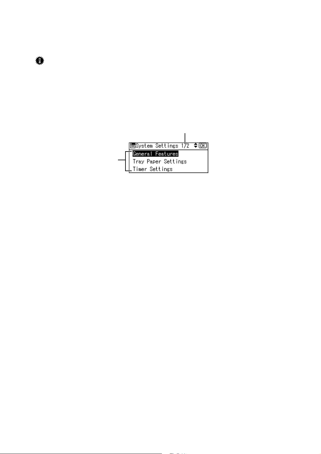
Display Panel
The display panel shows machine status, error messages, and function menus.
Important
❒ A force or impact of more than 30 N (about 3 kgf) will damage the display
panel.
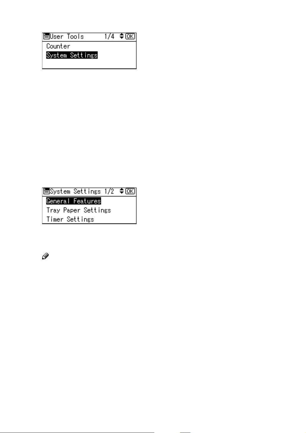
If you press the {User Tools/Counter} key, the User Tools Menu screen appears.
Using the System Settings menu screen as an example, this section explains how
to use the machine's display panel.
2
1
AME002S
1. The settings menu appears. Press
the {U} or {T} key to scroll to the
setting you want to specify or
change, and then press the {OK} key
to display the screen for specifying
that setting.
2. The number of pages in the dis-
played settings menu appears. If you
cannot see the entire menu, press the
{U} or {T} key to scroll the screen.
2
Page 11
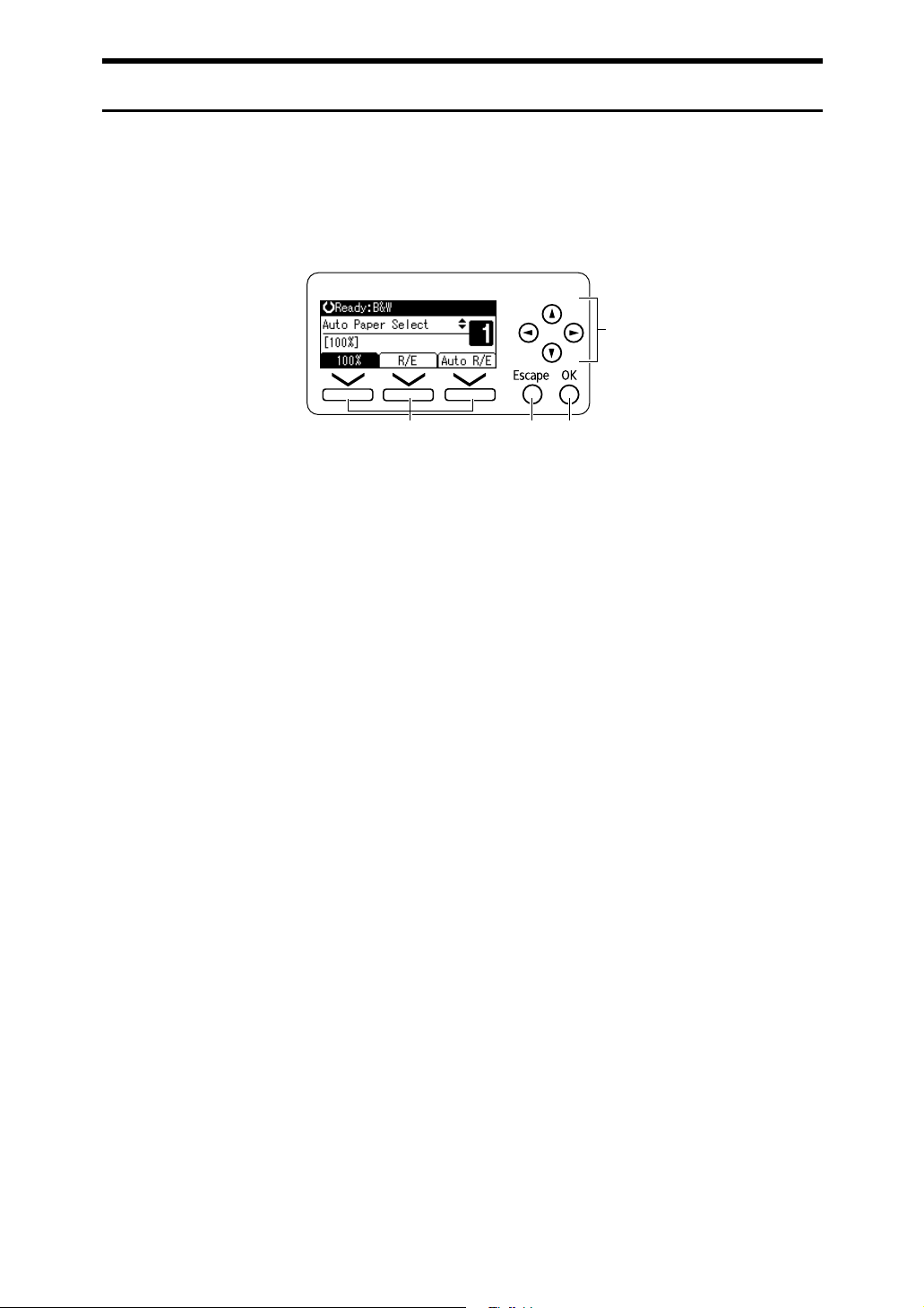
Reading the Display and Using Keys
This section explains how to read the display and use the Selection keys.
If you press the {Copy} key, the initial copy screen appears.
Using the initial copy screen menu as an example, this section explains how to
use the machine's control panel.
4
1 2 3
1. Selection keys
Correspond to items at the bottom line on
the display.
Example: The Copy display
• When the instruction “press {100%}”
appears in this manual, press the left
selection key.
• When the instruction “press {R/E}”
appears in this manual, press the centre selection key.
• When the instruction “press {Auto
R/E}” appears in this manual, press
the right selection key.
AMA058S
2. {Escape} key
Press to cancel an operation or return to
the previous display.
3. {OK} key
Press to set a selected item or an entered
numeric value.
4. Scroll keys
Press to move the cursor in each direction, step by step.
When the {U}, {T}, {V} or {W} key appears in this manual, press the scroll key
of the same direction.
3
Page 12
Accessing User Tools (System Settings)
This section is for Administrators in charge of this machine.
User Tools allow you to change or set defaults.
Note
❒ Operations for system settings differ from normal operations. Always quit
User Tools when you have finished.
❒ Any changes you make with User Tools remain in effect even if the main
power switch or operation switch is turned off, or {Clear Modes} key is
pressed.
❒ Default settings are shown in bold type.
Reference
p.4 “Changing Default Settings”
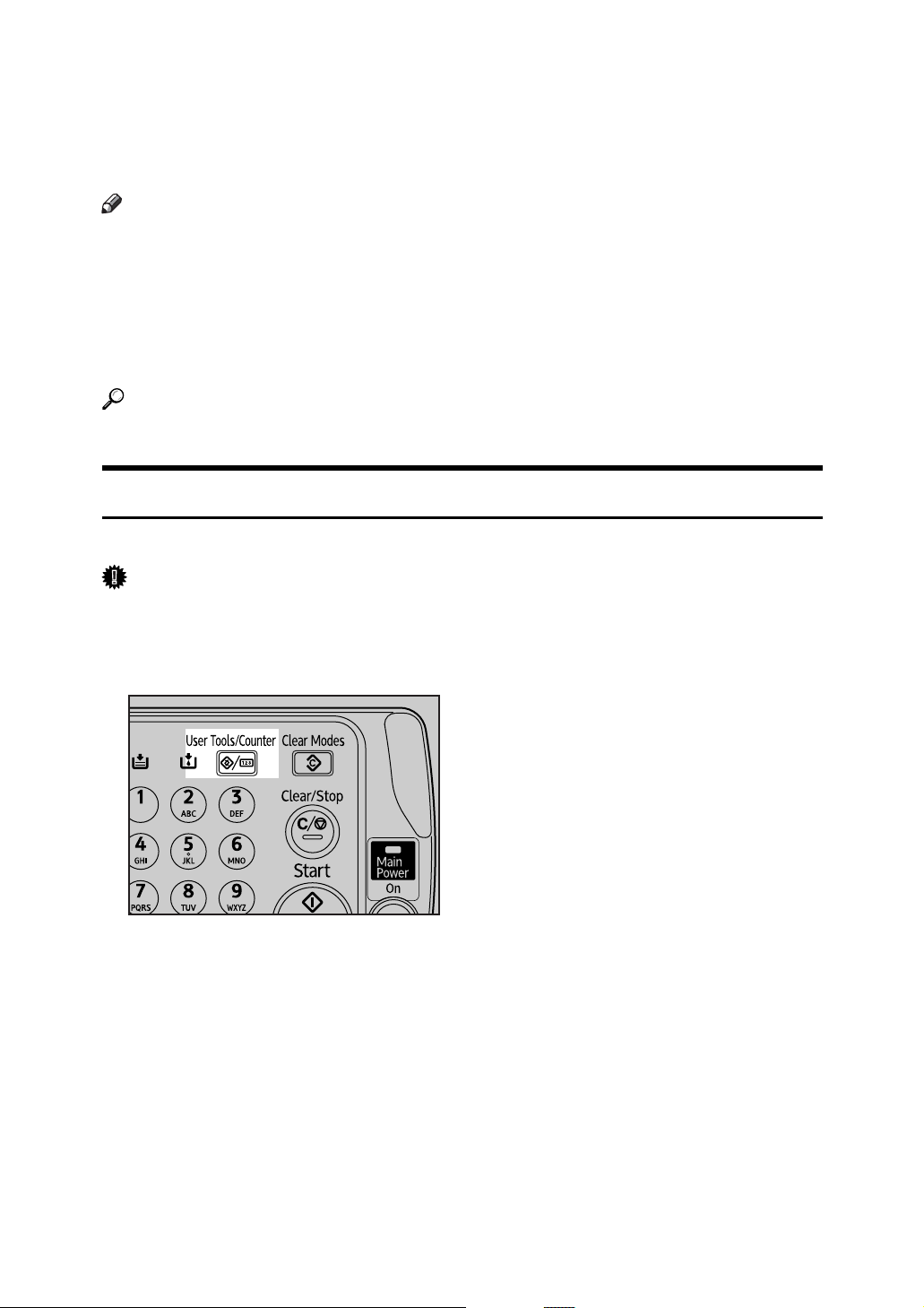
Changing Default Settings
This section describes how to change the settings of User Tools.
Important
❒ If Administrator Authentication Management is specified, contact your ad-
ministrator.
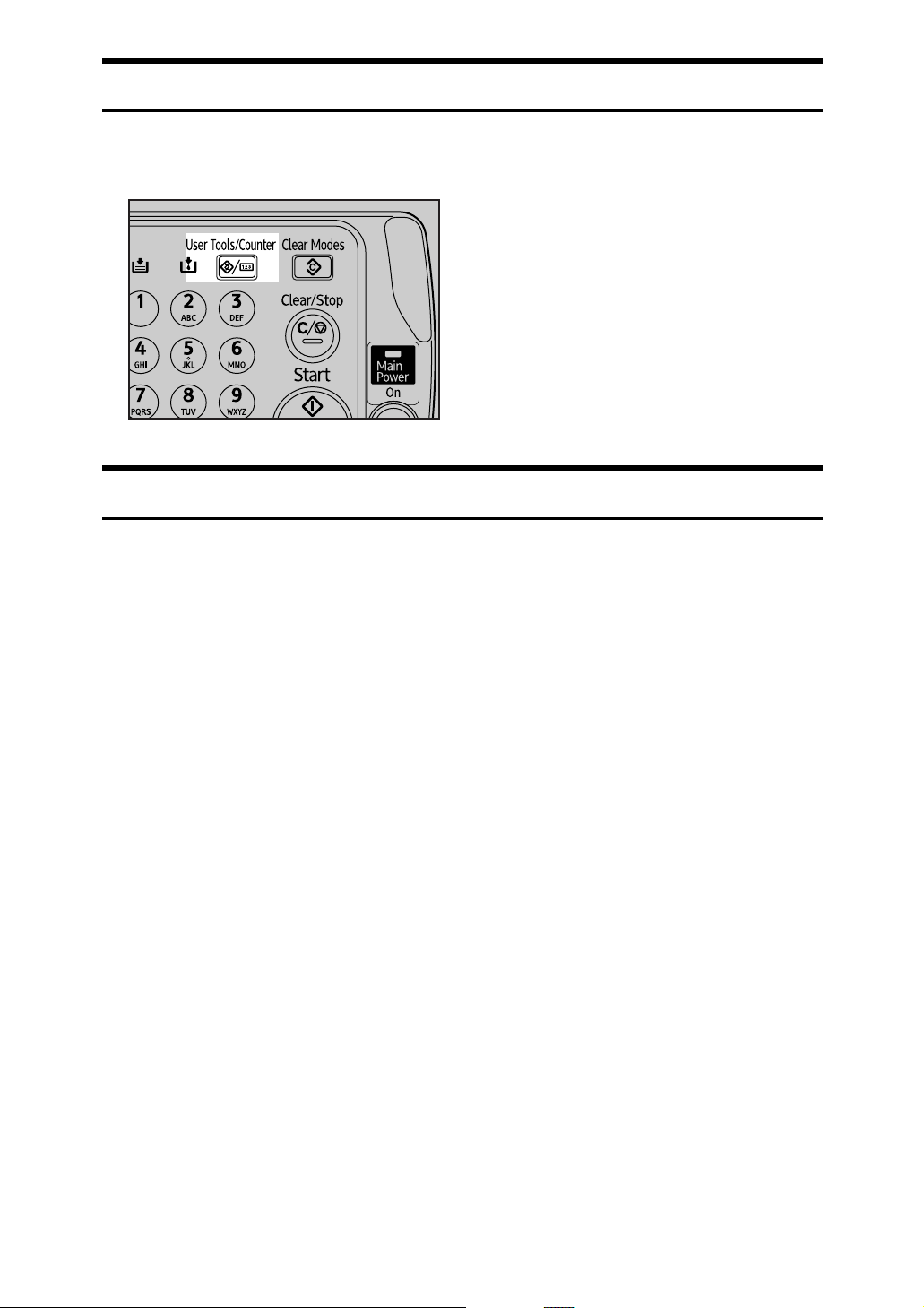
A Press the {User Tools/Counter} key.
AMA060S
4
Page 13
B Select the menu using {U} or {T}, and then press the {OK} key.
To change the System Settings, select [System Settings].
To change the Copier Features, select [Copier Features].
To change the Fax Features, select [Fax Features].
To change the Printer Features, select [Printer Features].
To change the Scanner Features, select [Scanner Features].
To adjust color registration or gradation, select [Maintenance].
To change the language used on the display, select [Language].
To check the telephone numbers to contact for repairs, or to order consumables, select [Enquiry].
To check the counter, select [Counter].
C Select the item using {U} or {T}, and then press the {OK} key.
D Change settings by following instructions on the display, and then press
the {OK} key.
Note
❒ Press the {Escape} key to return to the previous display.
❒ To cancel changes made to settings and return to the initial display, press
the {User Tools/Counter} key.
5
Page 14
Exiting User Tools
This section describes how to end User Tools.
A Press the {User Tools/Counter} key.
AMA060S
Menu Protect
Using Menu Protect, you can prevent unauthenticated users from changing the
user tools. Menu Protect can be specified for each of the following user tools
menus.
•Copier Features
• Fax Features
•Printer Features
• Scanner Features
For details, consult your administrator.
6
Page 15
1. Connecting the Machine
This chapter describes how to connect the machine to the network and specify
the network settings.
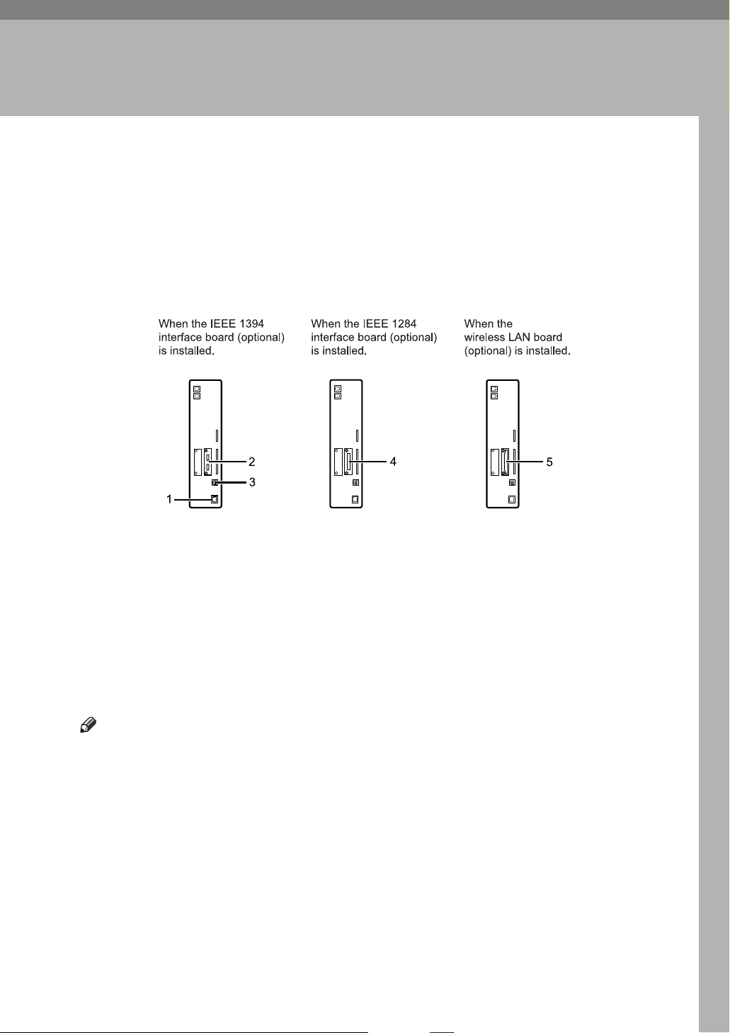
Connecting to the Interfaces
This section explains how to identify the machine’s interface and connect the
machine according to the network environment.
AME004S
1. 10BASE-T/100BASE-TX port
Port for connecting the 10BASE-T or
100BASE-TX cable
2. IEEE 1394 ports (optional)
Ports for connecting the IEEE 1394 interface cable
4. IEEE 1284 port (optional)
Port for connecting the IEEE 1284 interface cable
5. IEEE 802.11b (Wireless LAN) port
(optional)
Port for using the wireless LAN
3. USB port
Port for connecting the USB2.0 cable
Note
❒ You cannot install two or more of the options below: IEEE 1394 interface
board, IEEE 802.11b wireless LAN board, IEEE 1284 interface board.
7
Page 16
Connecting the Machine
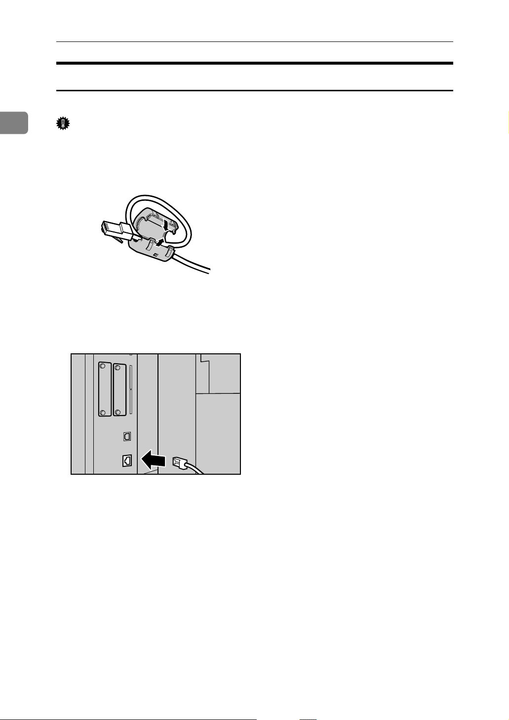
Connecting to the Ethernet Interface
Connect 10BASE-T or 100BASE-TX cable to the Ethernet interface.
1
Important
❒ If the main power switch is on, turn it off.
A Loop the network interface cable and attach the ferrite core.
AEW017S
B Make sure the main power switch of the machine is off.
C Connect the Ethernet interface cable to the 10BASE-T/100BASE-TX port.
AMB004S
D Connect the other end of the Ethernet cable to a network connection device
such as a hub.
8
Page 17
E Turn on the main power switch of the machine.
AME005S
Connecting to the Interfaces
1
1. Indicator (green)
Lights up green when the machine is
connected correctly to the network.
Note
❒ For details about installing the printer driver, see “Preparing the Ma-
chine”, Printer Reference.
Reference
“Turning On the Power” About This Machine
“Preparing the Machine”, Printer Reference
2. Indicator (yellow)
Lights up yellow when 100 BASE-TX
is in operation. Goes off when 10
BASE-T is in operation.
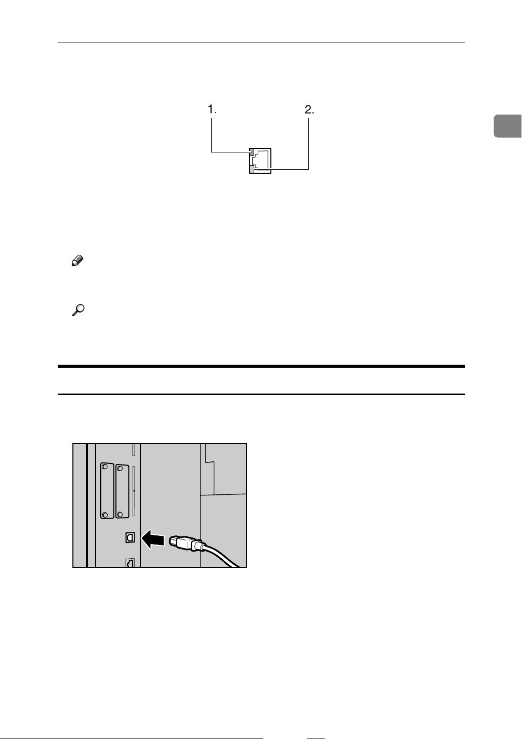
Connecting to the USB Interface
Connect the USB2.0 interface cable to the USB2.0 port.
A Connect the USB2.0 interface cable to the USB2.0 port.
AMB004S
B Connect the other end to the USB port on the host computer.
9
Page 18
1
Connecting the Machine
Note
❒ This machine does not come with a USB interface cable. Make sure you
purchase the appropriate cable for the machine and your computer.
❒ The USB 2.0 interface board is supported by WindowsMe / 2000 / XP,
Windows Server 2003, Mac OS X10.3.3 or higher.
• For WindowsMe:
Make sure to install “USB Printing Support”. When used with WindowsMe, only a speed equal to that of USB 1.1 is possible.
•For Mac OS:
To use Macintosh, the machine must be equipped with the optional
PostScript 3 unit. When used with Mac OS X10.3.3 or higher, a transfer
speed of USB 2.0 is supported.
❒ For details about installing the printer driver, see “Preparing the Ma-
chine”, Printer Reference.
Reference
“Preparing the Machine”, Printer Reference
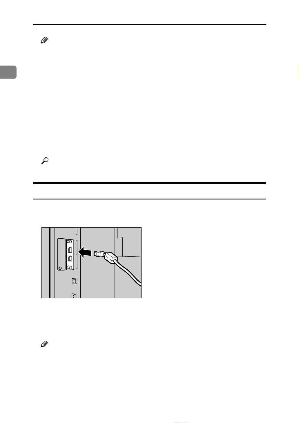
Connecting to the IEEE 1394 Interface (SCSI print/IPv4 over 1394)
Connect the IEEE 1394 interface cable to the IEEE 1394 interface board.
A Connect the IEEE 1394 interface cable to the IEEE 1394 port.
AMB006S
B Connect the other end of the cable into the interface connector on the host
computer.
Check the shape of the connector to the computer. Connect the cable firmly.
Note
❒
Use the interface cable supplied with the optional IEEE 1394 interface board.
❒ Two interface ports are available for connecting the IEEE 1394 interface ca-
ble. Either is suitable.
❒ If you have an interface that has with a ferrite core, connect the end that is
nearest the ferrite core to the machine.
❒ For details about installing the printer driver, see “Preparing the Ma-
10
chine”, Printer Reference.
Page 19
Reference
“Preparing the Machine”, Printer Reference
Connecting to the Interfaces
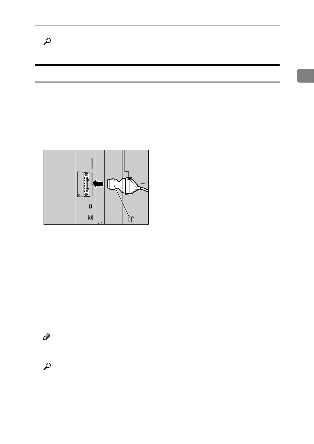
Connecting to the IEEE 1284 Interface
Connect the IEEE 1284 interface cable to the IEEE 1284 interface board.
A Make sure the main power switch on the machine is off.
If the main power switch is on, turn it off.
B Turn off the main power switch of the host computer.
C Connect the IEEE 1284 interface cable to the IEEE 1284 port.
AMD013S
Use the conversion connector (1) supplied with the IEEE 1284 interface board.
1
D Connect the other end of the cable into the interface connector on the host
computer.
Check the shape of the connector to the computer. Connect the cable firmly.
E Turn on the main power switch of the machine.
F Turn on the host computer.
When using Windows 95/98/Me/2000/XP and Windows Server 2003, a
printer driver installation screen might appear when the computer is turned
on. If this happens, click [Cancel] on the screen.
Note
❒ For details about installing the printer driver, see “Preparing the Ma-
chine”, Printer Reference.
Reference
“Turning On the Power” About This Machine
“Preparing the Machine”, Printer Reference
11
Page 20
Connecting the Machine
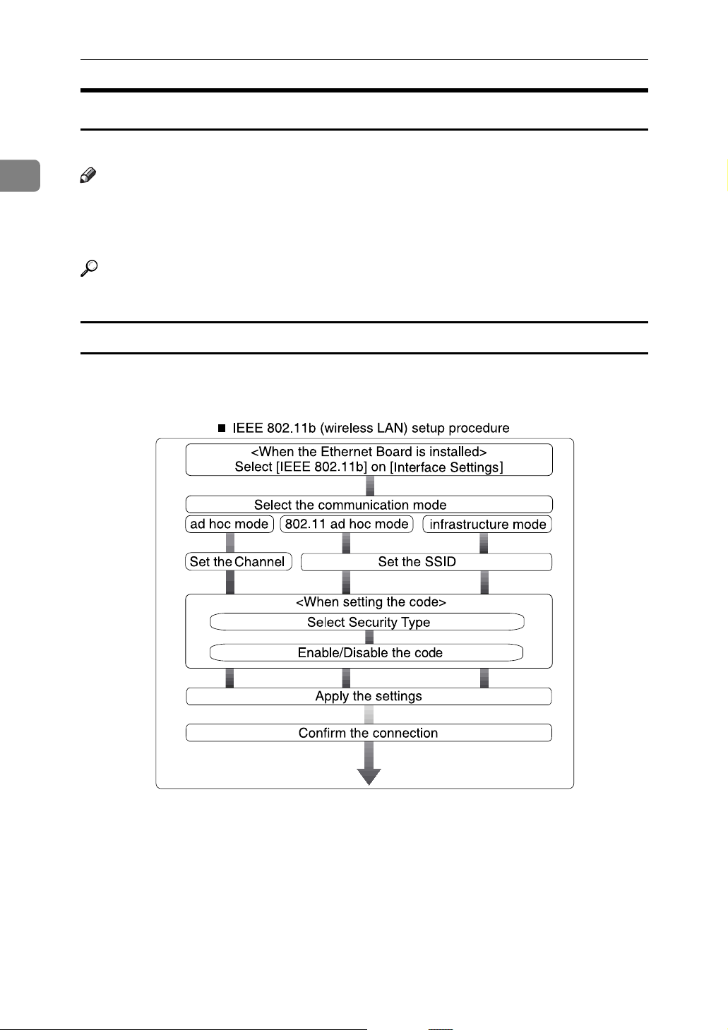
Connecting to the IEEE 802.11b (Wireless LAN) Interface
Connect to the IEEE 802.11b (wireless LAN) interface.
1
Note
❒ Check the settings of the IPv4 address and subnet mask of this machine.
❒ For details about how to set the IPv4 address and subnet mask from the con-
trol panel of the machine, see “Interface Settings”.
Reference
p.54 “Network”
Setup Procedure
Set up IEEE 802.11b (wireless LAN) according to the following procedure:
12
AME006S
Page 21
Connecting to the Interfaces
Note
❒ Select [802.11 Ad hoc] mode when connecting Windows XP as a wireless LAN
client using Windows XP standard driver or utilities, or when not using the
infrastructure mode.
❒ For details about how to specify wireless LAN settings from the control panel
on the machine, see “IEEE 802.11b”.
❒ For details about how to specify wireless LAN settings from other than the
control panel on the machine, see “Using Utilities to Make Settings”.
❒ For details about the setting items, see “IEEE 802.11b”.
Reference
p.61 “IEEE 802.11b”
p.35 “Using Utilities to Make Network Settings”
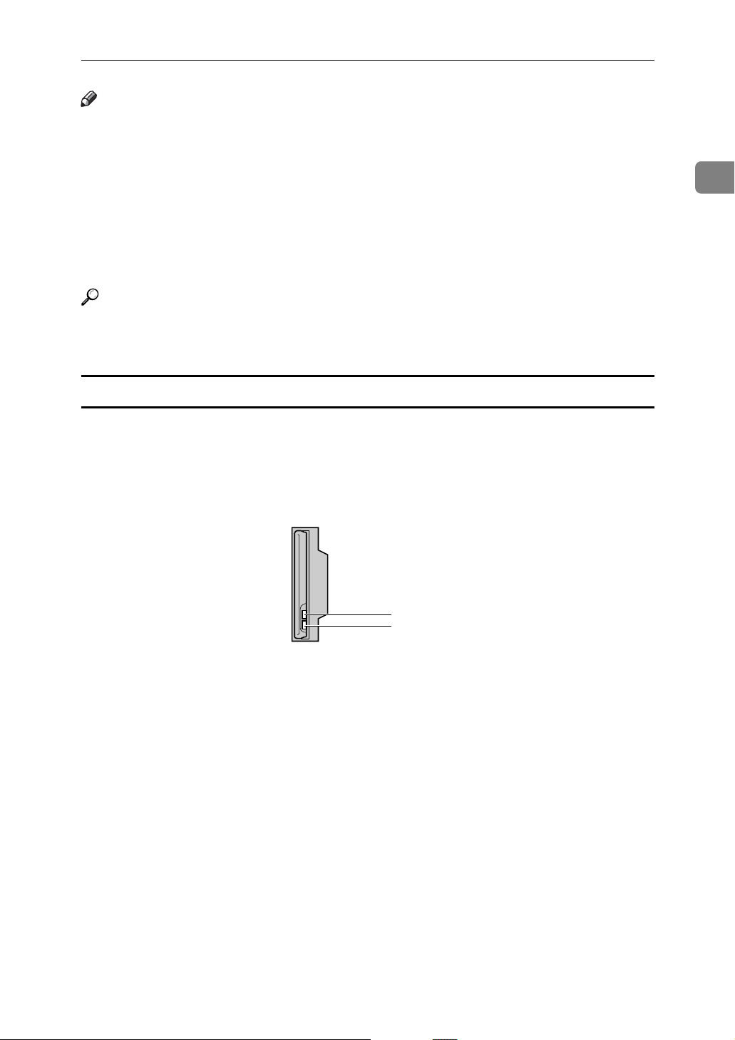
Checking the Connection
Check the wireless LAN connection.
Make sure the LED of the IEEE 802.11b interface unit is lit.
1
❖ When using in infrastructure mode
1. If [LAN Type] on the [Interface Set-
tings] / [Network] screen is not set to
[IEEE 802.11b], it does not light, even
if the main power is on.
1
2
ZGDH600J
2. If it is connected properly to the
network, the LED is green when in
infrastructure mode. If the LED is
blinking, the machine is searching
for devices.
13
Page 22

1
Connecting the Machine
❖ When using in adhoc mode / 802.11 ad hoc mode
1
2
ZGDH600J
1. If the IEEE 802.11b interface unit
is functioning, the LED lights up in
orange.
2. If it is connected properly to the
network, the LED is green when in
ad hoc mode or 802.11 ad hoc mode.
If the LED is blinking, the machine
is searching for devices. The LED
will light after a few seconds.
Print the configuration page to verify settings.
Note
❒ For details about printing a configuration page, see “Print I/F Settings”.
Reference
p.62 “Print I/F Settings”
14
Page 23

Connecting to the Interfaces
Checking the Signal
When using in infrastructure mode, you can check the machine's radio wave status using the control panel.
A Select [System Settings] using {U} or {T}, and then press the {OK} key.
B Select [Interface Settings] using {U} or {T}, and then press the {OK} key.
C Select [IEEE 802.11b] using {U} or {T}, and then press the {OK} key.
D Select [Wireless LAN Signal] using {U} or {T}, and then press the {OK} key.
The machine's radio wave status appears.
E After checking radio wave status, press the {OK} key.
F Press the {User Tools/Counter} key to return to the User Tools/Counter menu.
Note
❒ To check the radio wave status, press [IEEE 802.11b] under [LAN Type] in Net-
work menu of Interface Setting.
❒ For the procedure of entering the System Settings, see “Accessing user Tools
(System Settings)”.
1
Reference
p.4 “Accessing User Tools (System Settings)”
p.35 “Using Utilities to Make Network Settings”
p.61 “IEEE 802.11b”
15
Page 24

1
Connecting the Machine
Network Settings
This section describes the network settings you can change with User Tool (System Settings). Make settings according to functions you want to use and the interface to be connected.
Important
❒ These settings should be made by the system administrator, or with the ad-
vice the system administrator.
Settings Required to Use the Printer/LAN-Fax
This section lists the settings required for using the printer or LAN-Fax function.
Ethernet
This section lists the settings required for using the printer or LAN-Fax function
with an Ethernet connection.
For details about how to specify the settings, see “Interface Setting”.
Menu User Tool Setting Requirements
Interface Setting/Network Machine IPv4 Address Necessary
Interface Setting/Network IPv4 Gateway Address As required
Interface Setting/Network Machine IPv6 Address As required
Interface Setting/Network IPv6 Gateway Address As required
Interface Setting/Network IPv6 Stateless Setting As required
Interface Setting/Network DNS Configuration As required
Interface Setting/Network DDNS Configuration As required
Interface Setting/Network Domain As required
Interface Setting/Network WINS Configuration As required
Interface Setting/Network Effective Protocol Necessary
Interface Setting/Network NCP Del. Protocol As required
Interface Setting/Network NW Frame Type As required
Interface Setting/Network SMB Computer Name As required
Interface Setting/Network SMB Work Group As required
Interface Setting/Network Ethernet Speed As required
Interface Setting/Network LAN Type Necessary
16
Page 25

Network Settings
Menu User Tool Setting Requirements
Interface Setting/Network Permit SNMPv3 Communictn. As required
Interface Setting/Network Permit SSL/TLS Comm. As required
Interface Setting/Network Host Name As required
Interface Setting/Network Machine Name As required
Note
❒ IPv6 can be used only for the printer function.
❒ In [Effective Protocol], check that the protocol you want to use is set to [Effec-
tive].
❒ [LAN Type] is displayed when the wireless LAN board is installed. If Ethernet
and IEEE 802.11b (wireless LAN) are both connected, the selected interface
has priority.
Reference
p.54 “Interface Settings”
IEEE 1394 (IPv4 over 1394)
This section lists the settings required for using the printer or LAN-Fax function
with IEEE 1394 interface cable.
For details about how to specify the settings, see “Interface Setting”.
Menu User Tool Setting Requirements
1
Interface Setting/IEEE 1394
Interface Setting/IEEE 1394
Interface Setting/IEEE 1394
Interface Setting/IEEE 1394
Interface Setting/IEEE 1394
Interface Setting/IEEE 1394
Interface Setting/Network IPv4 Gateway Address As required
Interface Setting/Network DNS Configuration As required
Interface Setting/Network Effective Protocol Necessary
IPv4 Address Necessary
DDNS Configuration As required
Host Name As required
Domain Name As required
WINS Configuration As required
IPv4 over 1394 Necessary
Note
❒ [IEEE 1394] appears when optional IEEE 1394 interface board is installed.
❒
In [Effective Protocol], check that the protocol you want to use is set to [Effective].
Reference
p.54 “Interface Settings”
17
Page 26

1
Connecting the Machine
IEEE 802.11b (wireless LAN)
This section lists the settings required for using the printer or LAN-Fax function
with IEEE 802.11b (wireless LAN).
For details about how to specify the settings, see “Interface Setting”.
Menu User Tool Setting Requirements
Interface Setting/Network Machine IPv4 Address Necessary
Interface Setting/Network IPv4 Gateway Address As required
Interface Setting/Network Machine IPv6 Address As required
Interface Setting/Network IPv6 Gateway Address As required
Interface Setting/Network IPv6 Stateless Setting As required
Interface Setting/Network DNS Configuration As required
Interface Setting/Network DDNS Configuration As required
Interface Setting/Network Domain As required
Interface Setting/Network WINS Configuration As required
Interface Setting/Network Effective Protocol Necessary
Interface Setting/Network NCP Del. Protocol As required
Interface Setting/Network NW Frame Type As required
Interface Setting/Network SMB Computer Name As required
Interface Setting/Network SMB Work Group As required
Interface Setting/Network LAN Type Necessary
Interface Setting/Network Permit SNMPv3 Communictn. As required
Interface Setting/Network Permit SSL/TLS Comm. As required
Interface Setting/Network Host Name As required
Interface Setting/Network Machine Name As required
Interface Setting/IEEE 802.11b
Interface Setting/IEEE 802.11b
Interface Setting/IEEE 802.11b
Interface Setting/IEEE 802.11b
Interface Setting/IEEE 802.11b
Communication Mode Necessary
SSID Setting As required
Channel As required
Security Type As required
Communication Speed As required
Note
❒
In [Effective Protocol], check that the protocol you want to use is set to [Effective].
❒ [IEEE 802.11b] and [LAN Type] are displayed when the wireless LAN interface
board is installed. If both Ethernet and wireless LAN (IEEE 802.11b) are connected, the selected interface takes precedence.
18
Reference
p.54 “Interface Settings”
Page 27

Settings Required to Use Internet Fax
This section lists the settings required for using Internet Fax.
Network Settings
Ethernet
This section lists the settings required for using Internet FAX.
For details about how to specify the settings, see “Interface Setting” and “File
Transfer”.
Menu User Tool Setting Requirements
Interface Setting/Network Machine IPv4 Address Necessary
Interface Setting/Network IPv4 Gateway Address Necessary
Interface Setting/Network DNS Configuration As required
Interface Setting/Network DDNS Configuration As required
Interface Setting/Network Domain As required
Interface Setting/Network WINS Configuration As required
Interface Setting/Network Effective Protocol Necessary
Interface Setting/Network Ethernet Speed As required
Interface Setting/Network LAN Type Necessary
Interface Setting/Network Permit SNMPv3 Communictn. As required
Interface Setting/Network Permit SSL/TLS Comm. As required
1
Interface Setting/Network Host Name As required
File Transfer SMTP Server Necessary
File Transfer SMTP Authentication As required
File Transfer POP before SMTP As required
File Transfer Reception Protocol As required
File Transfer POP3/IMAP4 Settings As required
File Transfer Key Operator's E-mail Add. As required
File Transfer E-mail Communication Port Necessary
File Transfer E-mail Recept. Interval As required
File Transfer Max. Recept. E-mail Size As required
File Transfer E-mail Storage in Server As required
File Transfer Fax E-mail Account Necessary
19
Page 28

1
Connecting the Machine
Note
❒ In [Effective Protocol], check that the protocol you want to use is set to [Effec-
tive].
❒ [LAN Type] is displayed when the wireless LAN interface board is installed. If
both Ethernet and wireless LAN (IEEE 802.11b) are connected, the selected interface takes precedence.
❒ [SMTP Server] and [Fax E-mail Account] must be specified in order to use the
send function.
❒ When [POP before SMTP] is set to [On], also make setting for [Reception Protocol]
and [POP3/IMAP4 Settings].
❒ When [SMTP Authentication] is set to [On], also make setting for [Key Operator's
E-mail Add.].
❒ [E-mail Communication Port] and [Fax E-mail Account] must be specified in order
to use the reception function.
❒ When setting [POP before SMTP] to [On], check [POP3] port number in [E-mail
Communication Port].
Reference
p.54 “Interface Settings”
p.63 “File Transfer”
IEEE 1394 (IPv4 over 1394)
This section lists the settings required for using Internet FAX with IEEE 1394 interface cable.
For details about how to specify the settings, see “Interface Setting” and “File
Transfer”.
Menu User Tool Setting Requirements
Interface Setting/IEEE 1394
Interface Setting/IEEE 1394
Interface Setting/IEEE 1394
Interface Setting/IEEE 1394
Interface Setting/IEEE 1394
Interface Setting/IEEE 1394
Interface Setting/Network IPv4 Gateway Address Necessary
Interface Setting/Network DNS Configuration As required
Interface Setting/Network Effective Protocol Necessary
IPv4 Address Necessary
DDNS Configuration As required
Host Name As required
Domain Name As required
WINS Configuration As required
IPv4 over 1394 Necessary
20
File Transfer SMTP Server Necessary
File Transfer SMTP Authentication As required
File Transfer POP before SMTP As required
File Transfer Reception Protocol As required
Page 29

Network Settings
Menu User Tool Setting Requirements
File Transfer POP3/IMAP4 Settings As required
File Transfer Key Operator's E-mail Add. As required
File Transfer E-mail Communication Port Necessary
File Transfer E-mail Recept. Interval As required
File Transfer Max. Recept. E-mail Size As required
File Transfer E-mail Storage in Server As required
File Transfer Fax E-mail Account Necessary
Note
❒ [IEEE 1394] is displayed when the IEEE 1394 interface board is installed.
❒ In [Effective Protocol], check that the protocol you want to use is set to [Effec-
tive].
❒ [SMTP Server] and [Fax E-mail Account] must be specified in order to use the
send function.
❒ When [POP before SMTP] is set to [On], also make setting for [Reception Protocol]
and [POP3/IMAP4 Settings].
❒ When [SMTP Authentication] is set to [On], also make setting for [Key Operator's
E-mail Add.].
❒ [E-mail Communication Port] and [Fax E-mail Account] must be specified in order
to use the reception function.
❒ When setting [POP before SMTP] to [On], check [POP3] port number in [E-mail
Communication Port].
1
Reference
p.54 “Interface Settings”
p.63 “File Transfer”
IEEE 802.11b (wireless LAN)
This section lists the settings required for using Internet FAX with IEEE 802.11b
(wireless LAN).
For details about how to specify the settings, see “Interface Setting” and “File
Transfer”.
Menu User Tool Setting Requirements
Interface Setting/Network Machine IPv4 Address Necessary
Interface Setting/Network IPv4 Gateway Address Necessary
Interface Setting/Network DNS Configuration As required
Interface Setting/Network DDNS Configuration As required
Interface Setting/Network Domain As required
Interface Setting/Network WINS Configuration As required
21
Page 30

Connecting the Machine
Menu User Tool Setting Requirements
Interface Setting/Network Effective Protocol Necessary
Interface Setting/Network LAN Type Necessary
1
Interface Setting/Network Permit SNMPv3 Communictn. As required
Interface Setting/Network Permit SSL/TLS Comm. As required
Interface Setting/Network Host Name As required
Interface Setting/IEEE 802.11b
Interface Setting/IEEE 802.11b
Interface Setting/IEEE 802.11b
Interface Setting/IEEE 802.11b
Interface Setting/IEEE 802.11b
File Transfer Setting SMTP Server Necessary
File Transfer SMTP Authentication As required
File Transfer POP before SMTP As required
File Transfer Reception Protocol As required
File Transfer POP3/IMAP4 settings As required
File Transfer Key Operator's E-mail Add. As required
File Transfer E-mail Communication Port Necessary
File Transfer E-mail Recept. Interval As required
File Transfer Max. Recept. E-mail Size As required
Communication Mode Necessary
SSID Setting As required
Channel As required
Security Type As required
Communication Speed As required
File Transfer E-mail Storage in Server As required
File Transfer Fax E-mail Account Necessary
Note
❒ In [Effective Protocol], check that the protocol you want to use is set to [Effec-
tive].
❒ [IEEE 802.11b] and [LAN Type] are displayed when the wireless LAN interface
board is installed. If both Ethernet and wireless LAN (IEEE 802.11b) are connected, the selected interface takes precedence.
❒ [SMTP Server] and [Fax E-mail Account] must be specified in order to use the
send function.
❒ When [POP before SMTP] is set to [On], also make setting for [Reception Protocol]
and [POP3/IMAP4 Settings].
❒ When [SMTP Authentication] is set to [On], also make setting for [Key Operator's
E-mail Add.].
❒ [E-mail Communication Port] and [Fax E-mail Account] must be specified in order
to use the reception function.
❒ When setting [POP before SMTP] to [On], check [POP3] port number in [E-mail
Communication Port].
22
Page 31

Network Settings
Reference
p.54 “Interface Settings”
p.63 “File Transfer”
Settings Required to Use E-mail Function
This section lists the settings required for sending e-mail.
Ethernet
This section lists the settings required for sending e-mail with Ethernet cable.
For details about how to specify the settings, see “Interface Setting” and “File
Transfer”.
Menu User Tool Setting Requirements
Interface Setting/Network Machine IPv4 Address Necessary
Interface Setting/Network IPv4 Gateway Address Necessary
Interface Setting/Network DNS Configuration As required
1
Interface Setting/Network DDNS Configuration As required
Interface Setting/Network Domain As required
Interface Setting/Network WINS Configuration As required
Interface Setting/Network Effective Protocol Necessary
Interface Setting/Network Ethernet Speed As required
Interface Setting/Network LAN Type Necessary
Interface Setting/Network Permit SNMPv3 Communictn. As required
Interface Setting/Network Host Name As required
File Transfer SMTP Server Necessary
File Transfer SMTP Authentication As required
File Transfer POP before SMTP As required
File Transfer Reception Protocol As required
File Transfer POP3/IMAP4 Settings As required
File Transfer Key Operator's E-mail Add. As required
File Transfer E-mail Communication Port As required
File Transfer Scanner Resend Time As required
File Transfer Scanner Resend Setting As required
23
Page 32

1
Connecting the Machine
Note
❒ In [Effective Protocol], check that the protocol you want to use is set to [Effec-
tive].
❒ [LAN Type] is displayed when the wireless LAN interface board is installed. If
both ethernet and wireless LAN (IEEE 802.11b) are connected, the selected interface takes precedence.
❒ When [POP before SMTP] is set to [On], also make setting for [Reception Protocol]
and [POP3/IMAP4 Settings].
❒ When setting [POP before SMTP] to [On], check [POP3] port number in [E-mail
Communication Port].
Reference
p.54 “Interface Settings”
p.63 “File Transfer”
IEEE 1394 (IPv4 over 1394)
This section lists the settings required for sending e-mail with IEEE 1394 interface cable.
For details about how to specify the settings, see “Interface Setting” and “File
Transfer”.
Menu User Tool Setting Requirements
Interface Setting/IEEE 1394
Interface Setting/IEEE 1394
Interface Setting/IEEE 1394
Interface Setting/IEEE 1394
Interface Setting/IEEE 1394
Interface Setting/IEEE 1394
Interface Setting/Network IPv4 Gateway Address Necessary
Interface Setting/Network DNS Configuration As required
Interface Setting/Network Effective Protocol Necessary
File Transfer SMTP Server Necessary
File Transfer SMTP Authentication As required
File Transfer Setting POP before SMTP As required
File Transfer Setting Reception Protocol As required
File Transfer Setting POP3/IMAP4 Settings As required
File Transfer Setting Key Operator's E-mail Add. As required
File Transfer Setting E-mail Communication Port As required
IPv4 Address Necessary
DDNS Configuration As required
Host Name As required
Domain Name As required
WINS Configuration As required
IPv4 over 1394 Necessary
24
File Transfer Setting Scanner Resend Time As required
File Transfer Setting Scanner Resend setting As required
Page 33

Network Settings
Note
❒ [IEEE 1394] is displayed when the IEEE 1394 interface board is installed.
❒ In [Effective Protocol], check that the protocol you want to use is set to [Effec-
tive].
❒ When [POP before SMTP] is set to [On], also make setting for [Reception Protocol]
and [POP3/IMAP4 Settings].
❒ When setting [POP before SMTP] to [On], check [POP3] port number in [E-mail
Communication Port].
Reference
p.54 “Interface Settings”
p.63 “File Transfer”
IEEE 802.11b (wireless LAN)
This section lists the settings required for sending e-mail with IEEE 802.11b
(wireless LAN).
For details about how to specify the settings, see “Interface Setting” and “File
Transfer”.
1
Menu User Tool Setting Requirements
Interface Setting/Network Machine IPv4 Address Necessary
Interface Setting/Network IPv4 Gateway Address Necessary
Interface Setting/Network DNS Configuration As required
Interface Setting/Network DDNS Configuration As required
Interface Setting/Network Domain As required
Interface Setting/Network WINS Configuration As required
Interface Setting/Network Effective Protocol Necessary
Interface Setting/Network LAN Type Necessary
Interface Setting/Network Permit SNMPv3 Communictn. As required
Interface Setting/Network Permit SSL/TLS Comm. As required
Interface Setting/Network Host Name As required
Interface Setting/IEEE 802.11b
Interface Setting/IEEE 802.11b
Interface Setting/IEEE 802.11b
Interface Setting/IEEE 802.11b
Interface Setting/IEEE 802.11b
Communication Mode Necessary
SDID Setting As required
Channel As required
Security Type As required
Communication Speed As required
File Transfer Setting SMTP Server Necessary
File Transfer Setting SMTP Authentication As required
File Transfer Setting POP before SMTP As required
25
Page 34

Connecting the Machine
Menu User Tool Setting Requirements
File Transfer Setting Reception Protocol As required
File Transfer Setting POP3/IMAP4 Settings As required
1
File Transfer Setting Key Operator's E-mail Add. As required
File Transfer Setting E-mail Communication Port As required
File Transfer Setting Scanner Resend Time As required
File Transfer Setting Scanner Resend Setting As required
Note
❒ In [Effective Protocol], check that the protocol you want to use is set to [Effec-
tive].
❒ [LAN Type] is displayed when the wireless LAN interface board is installed. If
both ethernet and wireless LAN (IEEE 802.11b) are connected, the selected interface takes precedence.
❒ When [POP before SMTP] is set to [On], also make setting for [Reception Protocol]
and [POP3/IMAP4 Settings].
❒ When setting [POP before SMTP] to [On], check [POP3] port number in [E-mail
Communication Port].
Reference
p.54 “Interface Settings”
p.63 “File Transfer”
Settings Required to Use Scan to Folder Function
This section lists the settings required for sending file.
Ethernet
This section lists the settings required for sending file with ethernet cable.
For details about how to specify the settings, see “Interface Setting” and “File
Transfer”.
Menu User Tool Setting Requirements
Interface Setting/Network Machine IPv4 Address Necessary
Interface Setting/Network IPv4 Gateway Address Necessary
Interface Setting/Network DNS Configuration As required
Interface Setting/Network DDNS Configuration As required
Interface Setting/Network Domain As required
Interface Setting/Network WINS Configuration As required
Interface Setting/Network Effective Protocol Necessary
Interface Setting/Network LAN Type Necessary
26
Page 35

Network Settings
Menu User Tool Setting Requirements
Interface Setting/Network Permit SNMPv3 Communictn. As required
Interface Setting/Network Permit SSL/TLS Comm. As required
Interface Setting/Network Host Name As required
File Transfer Setting Default User Name/PW(Send) As required
File Transfer Setting Scanner Resend Time As required
File Transfer Setting Scanner Resend Setting As required
Note
❒
In [Effective Protocol], check that the protocol you want to use is set to [Effective].
❒ [LAN Type] is displayed when the wireless LAN interface board is installed. If
both ethernet and wireless LAN (IEEE 802.11b) are connected, the selected interface takes precedence.
Reference
p.54 “Interface Settings”
p.63 “File Transfer”
IEEE 1394 (IPv4 over 1394)
This section lists the settings required for sending file with IEEE 1394 interface
cable.
For details about how to specify the settings, see “Interface Setting” and “File
Transfer”.
1
Menu User Tool Setting Requirements
Interface Setting/IEEE 1394
Interface Setting/IEEE 1394
Interface Setting/IEEE 1394
Interface Setting/IEEE 1394
Interface Setting/IEEE 1394
Interface Setting/IEEE 1394
Interface Setting/Network IPv4 Gateway Address Necessary
Interface Setting/Network DNS Configuration As required
Interface Setting/Network Effective Protocol Necessary
File Transfer Setting Default User Name/PW(Send) As required
File Transfer Setting Scanner Resend Time As required
File Transfer Setting Scanner Resend Setting As required
IPv4 Address Necessary
DDNS Configuration As required
Host Name As required
Domain Name As required
WINS Configuration As required
IPv4 over 1394 Necessary
Note
❒ [IEEE 1394] is displayed when the IEEE 1394 interface board is installed.
In [Effective Protocol], check that the protocol you want to use is set to [Effective].
❒
27
Page 36

Connecting the Machine
Reference
p.54 “Interface Settings”
p.63 “File Transfer”
1
IEEE 802.11b (wireless LAN)
This section lists the settings required for sending file with IEEE 802.11b (wireless LAN).
For details about how to specify the settings, see “Interface Setting” and “File
Transfer”.
Menu User Tool Setting Requirements
Interface Setting/Network Machine IPv4 Address Necessary
Interface Setting/Network IPv4 Gateway Address Necessary
Interface Setting/Network DNS Configuration As required
Interface Setting/Network DDNS Configuration As required
Interface Setting/Network Domain As required
Interface Setting/Network WINS Configuration As required
Interface Setting/Network Effective Protocol Necessary
Interface Setting/Network LAN Type Necessary
Interface Setting/Network Permit SNMPv3 Communictn. As required
Interface Setting/Network Permit SSL/TLS Comm. As required
Interface Setting/Network Host Name As required
Interface Setting/IEEE 802.11b
Interface Setting/IEEE 802.11b
Interface Setting/IEEE 802.11b
Interface Setting/IEEE 802.11b
Interface Setting/IEEE 802.11b
File Transfer Setting Default User Name/PW(Send) As required
File Transfer Setting Scanner Resend Time As required
File Transfer Setting Scanner Resend Setting As required
Communication Mode Necessary
SSID Setting As required
Channel As required
Security Type As required
Communication Speed As required
Note
❒
In [Effective Protocol], check that the protocol you want to use is set to [Effective].
❒ [IEEE 802.11b] and [LAN Type] are displayed when the wireless LAN interface
board is installed. If both ethernet and wireless LAN (IEEE 802.11b) are connected, the selected interface takes precedence.
Reference
p.54 “Interface Settings”
p.63 “File Transfer”
28
Page 37

Network Settings
Settings Required to Use the Network Delivery Scanner
This section lists the settings required for delivering data to network.
Ethernet
This section lists the settings required for delivering data to network with ethernet cable.
For details about how to specify the settings, see “Interface Setting” and “File
Transfer”.
Menu User Tool Setting Requirements
Interface Setting/Network Machine IPv4 Address Necessary
Interface Setting/Network IPv4 Gateway Address As required
Interface Setting/Network DNS Configuration As required
Interface Setting/Network DDNS Configuration As required
Interface Setting/Network Domain As required
Interface Setting/Network WINS Configuration As required
Interface Setting/Network Effective Protocol Necessary
Interface Setting/Network Ethernet Speed As required
Interface Setting/Network LAN Type Necessary
Interface Setting/Network Permit SNMPv3 Communictn. As required
Interface Setting/Network Permit SSL/TLS Comm. As required
1
Interface Setting/Network Host Name As required
File Transfer Setting Delivery Option As required
File Transfer Setting Fax RX File Transmission As required
File Transfer Setting Scanner Resend Time As required
File Transfer Setting Scanner Resend Setting As required
Note
❒ In [Effective Protocol], check that the protocol you want to use is set to [Effec-
tive].
❒ [LAN Type] is displayed when the wireless LAN interface board is installed.
When both ethernet and wireless LAN (IEEE 802.11b) are connected, the selected interface takes precedence.
❒ If [Delivery Option] is set to [On], check that IPv4 Address is set.
Reference
p.54 “Interface Settings”
p.63 “File Transfer”
29
Page 38

1
Connecting the Machine
IEEE 1394 (IPv4 over 1394)
This section lists the settings required for delivering data to network with IEEE
1394 interface cable.
For details about how to specify the settings, see “Interface Setting” and “File
Transfer”.
Menu User Tool Setting Requirements
Interface Setting/IEEE 1394
Interface Setting/IEEE 1394
Interface Setting/IEEE 1394
Interface Setting/IEEE 1394
Interface Setting/IEEE 1394
Interface Setting/IEEE 1394
Interface Setting/Network IPv4 Gateway Address As required
Interface Setting/Network DNS Configuration As required
Interface Setting/Network Effective Protocol Necessary
File Transfer Setting Delivery Option As required
File Transfer Setting Fax RX File Transmission As required
File Transfer Setting Scanner Resend Time As required
File Transfer Setting Scanner Resend Setting As required
IPv4 Address Necessary
DDNS Configuration As required
Host Name As required
Domain Name As required
WINS Configuration As required
IPv4 over 1394 Necessary
Note
❒ [IEEE 1394] is displayed when the IEEE 1394 interface board is installed.
❒ In [Effective Protocol], check that the protocol you want to use is set to [Effec-
tive].
❒ If [Delivery Option] is set to [On], check that IPv4 Address is set.
Reference
p.54 “Interface Settings”
p.63 “File Transfer”
30
Page 39

Network Settings
IEEE 802.11b (wireless LAN)
This section lists the settings required for delivering data to network with IEEE
802.11b (wireless LAN).
For details about how to specify the settings, see “Interface Setting” and “File
Transfer”.
Menu User Tool Setting Requirements
Interface Setting/Network Machine IPv4 Address Necessary
Interface Setting/Network IPv4 Gateway Address As required
Interface Setting/Network DNS Configuration As required
Interface Setting/Network DDNS Configuration As required
Interface Setting/Network Domain As required
Interface Setting/Network WINS Configuration As required
Interface Setting/Network Effective Protocol Necessary
Interface Setting/Network LAN Type Necessary
Interface Setting/Network Permit SNMPv3 Communictn. As required
1
Interface Setting/Network Permit SSL/TLS Comm. As required
Interface Setting/Network Host Name As required
Interface Setting/IEEE 802.11b
Interface Setting/IEEE 802.11b
Interface Setting/IEEE 802.11b
Interface Setting/IEEE 802.11b
Interface Setting/IEEE 802.11b
File Transfer Setting Delivery Option As required
File Transfer Setting Fax RX File Transmission As required
File Transfer Setting Scanner Resend Time As required
File Transfer Setting Scanner Resend Setting As required
Communication Mode Necessary
SSID Setting As required
Channel As required
Security Type As required
Communication Speed As required
Note
❒ In [Effective Protocol], check that the protocol you want to use is set to [Effec-
tive].
❒ [IEEE 802.11b] and [LAN Type] are displayed when the wireless LAN interface
board is installed. When both Ethernet and wireless LAN (IEEE 802.11b) are
connected, the selected interface takes precedence.
❒ If [Delivery Option] is set to [On], check that IPv4 Address is set.
Reference
p.54 “Interface Settings”
p.63 “File Transfer”
31
Page 40

1
Connecting the Machine
Settings Required to Use Network TWAIN Scanner
This section lists the settings required for using TWAIN Scanner under the network environment.
Ethernet
This section lists the settings required for using network TWAIN Scanner with
Ethernet cable.
For details about how to specify the settings, see “Interface Setting”.
Menu User Tool Setting Requirements
Interface Setting/Network Machine IPv4 Address Necessary
Interface Setting/Network IPv4 Gateway Address As required
Interface Setting/Network DNS Configuration As required
Interface Setting/Network DDNS Configuration As required
Interface Setting/Network Domain As required
Interface Setting/Network WINS Configuration As required
Interface Setting/Network Effective Protocol Necessary
Interface Setting/Network LAN Type Necessary
Interface Setting/Network Ethernet Speed As required
Interface Setting/Network Permit SNMPv3 Communictn. As required
Interface Setting/Network Permit SSL/TLS Comm. As required
Interface Setting/Network Host Name As required
Note
❒ In [Effective Protocol], check that the protocol you want to use is set to [Effec-
tive].
❒ [LAN Type] is displayed when the wireless LAN interface board is installed.
When both Ethernet and wireless LAN (IEEE 802.11b) are connected, the selected interface takes precedence.
Reference
p.54 “Interface Settings”
32
Page 41

Network Settings
IEEE 1394 (IPv4 over 1394)
This section lists the settings required for using network TWAIN Scanner with
IEEE 1394 interface cable.
For details about how to specify the settings, see “Interface Setting”.
Menu User Tool Setting Requirements
1
Interface Setting/IEEE 1394
Interface Setting/IEEE 1394
Interface Setting/IEEE 1394
Interface Setting/IEEE 1394
Interface Setting/IEEE 1394
Interface Setting/IEEE 1394
Interface Setting/Network IPv4 Gateway Address As required
Interface Setting/Network DNS Configuration As required
Interface Setting/Network Effective Protocol Necessary
IPv4 Address Necessary
DDNS Configuration As required
Host Name As required
Domain Name As required
WINS Configuration As required
IPv4 over 1394 Necessary
Note
❒ [IEEE 1394] is displayed when the IEEE 1394 interface board is installed.
❒ In [Effective Protocol], check that the protocol you want to use is set to [Effec-
tive].
Reference
p.54 “Interface Settings”
33
Page 42

1
Connecting the Machine
IEEE 802.11b (wireless LAN)
This section lists the settings required for using network TWAIN Scanner with
IEEE 802.11b (wireless LAN).
For details about how to specify the settings, see “Interface Setting”.
Menu User Tool Setting Requirements
Interface Setting/Network Machine IPv4 Address Necessary
Interface Setting/Network IPv4 Gateway Address As required
Interface Setting/Network DNS Configuration As required
Interface Setting/Network DDNS Configuration As required
Interface Setting/Network Domain As required
Interface Setting/Network WINS Configuration As required
Interface Setting/Network Effective Protocol Necessary
Interface Setting/Network LAN Type Necessary
Interface Setting/Network Permit SNMPv3 Communictn. As required
Interface Setting/Network Permit SSL/TLS Comm. As required
Interface Setting/Network Host Name As required
Interface Setting/IEEE 802.11b
Interface Setting/IEEE 802.11b
Interface Setting/IEEE 802.11b
Interface Setting/IEEE 802.11b
Interface Setting/IEEE 802.11b
Communication Mode Necessary
SSDI Setting As required
Channel As required
Security Type As required
Communication Speed As required
Note
❒ In [Effective Protocol], check that the protocol you want to use is set to [Effec-
tive].
❒ [IEEE 802.11b] and [LAN Type] are displayed when the wireless LAN interface
board is installed. When both Ethernet and wireless LAN (IEEE 802.11b) are
connected, the selected interface takes precedence.
Reference
p.54 “Interface Settings”
34
Page 43

Network Settings
Using Utilities to Make Network Settings
You can also specify network settings using utilities such as Web Image Monitor,
SmartDeviceMonitor for Admin, and telnet.
Note
❒ For details about using Web Image Monitor, see “Using Web Image Moni-
tor”, Network Guide.
❒ For details about using SmartDeviceMonitor for Admin, see “Using SmartDe-
viceMonitor for Admin”, Network Guide.
❒ For Details about using telnet, see “Remote Maintenance by telnet”, Network
Guide.
Reference
“Using Web Image Monitor” Network Guide
“Using SmartDeviceMonitor for Admin” Network Guide
“Remote Maintenance by telnet”, Network Guide
1
Interface Settings
Change settings by using Web Image Monitor, SmartDeviceMonitor for Admin,
and telnet.
❖ [Network] → [Machine IPv4 Address] → [Auto-Obtain (DHCP)]
• Web Image Monitor: Can be used for specifying the setting.
• SmartDeviceMonitor for Admin: Can be used for specifying the setting.
• telnet: Can be used for specifying the setting.
❖ [Network] → [Machine IPv4 Address] → [Specify] → [IP Add.]
• Web Image Monitor: Can be used for specifying the setting.
• SmartDeviceMonitor for Admin: Can be used for specifying the setting.
• telnet: Can be used for specifying the setting.
❖ [Network] → [Machine IPv4 Address] → [Specify] → [Subnet M]
• Web Image Monitor: Can be used for specifying the setting.
• SmartDeviceMonitor for Admin: Can be used for specifying the setting.
• telnet: Can be used for specifying the setting.
❖ [Network] → [IPv4 Gateway Address]
• Web Image Monitor: Can be used for specifying the setting.
• SmartDeviceMonitor for Admin: Can be used for specifying the setting.
• telnet: Can be used for specifying the setting.
35
Page 44

Connecting the Machine
❖ [Network] → [Machine IPv6 Address] → [Manual Config. Address]
• Web Image Monitor: Can be used for specifying the setting.
• SmartDeviceMonitor for Admin: Cannot be used for specifying the setting.
1
• telnet: Can be used for specifying the setting.
❖ [Network] → [IPv6 Stateless Setting]
• Web Image Monitor: Can be used for specifying the setting.
• SmartDeviceMonitor for Admin: Cannot be used for specifying the setting.
• telnet: Can be used for specifying the setting.
❖ [Network] → [DNS Configuration] → [Auto-Obtain (DHCP)]
• Web Image Monitor: Can be used for specifying the setting.
• SmartDeviceMonitor for Admin: Cannot be used for specifying the setting.
• telnet: Can be used for specifying the setting.
❖ [Network] → [DNS Configuration] → [Specify] → [Server 1-3]
• Web Image Monitor: Can be used for specifying the setting.
• SmartDeviceMonitor for Admin: Cannot be used for specifying the setting.
• telnet: Can be used for specifying the setting.
❖ [Network] → [DDNS Configuration]
• Web Image Monitor: Can be used for specifying the setting.
• SmartDeviceMonitor for Admin: Cannot be used for specifying the setting.
• telnet: Can be used for specifying the setting.
❖ [Network] → [Domain] → [Auto-Obtain (DHCP)]
• Web Image Monitor: Can be used for specifying the setting.
• SmartDeviceMonitor for Admin: Cannot be used for specifying the setting.
• telnet: Can be used for specifying the setting.
❖ [Network] → [Domain] → [Specify] → [Domain]
• Web Image Monitor: Can be used for specifying the setting.
• SmartDeviceMonitor for Admin: Cannot be used for specifying the setting.
• telnet: Can be used for specifying the setting.
❖ [Network] → [WINS Configuration] → [On] → [Server 1-2]
• Web Image Monitor: Can be used for specifying the setting.
• SmartDeviceMonitor for Admin: Cannot be used for specifying the setting.
• telnet: Can be used for specifying the setting.
36
Page 45

Network Settings
❖ [Network] → [WINS Configuration] → [On] → [Scope ID]
• Web Image Monitor: Can be used for specifying the setting.
• SmartDeviceMonitor for Admin: Cannot be used for specifying the setting.
• telnet: Can be used for specifying the setting.
❖ [Network] → [Effective Protocol] → [IPv4]
• Web Image Monitor: Can be used for specifying the setting.
• SmartDeviceMonitor for Admin: When in communication with this machine with IPX/SPX, TCP/IP setting is enabled.
• telnet: Can be used for specifying the setting.
❖ [Network] → [Effective Protocol] → [IPv6]
• Web Image Monitor: Can be used for specifying the setting.
• SmartDeviceMonitor for Admin: Can be used for specifying the setting.
• telnet: Can be used for specifying the setting.
❖ [Network] → [Effective Protocol] → [NetWare]
• Web Image Monitor: Can be used for specifying the setting.
• SmartDeviceMonitor for Admin: When in communication with this machine with TCP/IP, NetWare (IPX/SPX) setting is enabled.
• telnet: Can be used for specifying the setting.
❖ [Network] → [Effective Protocol] → [SMB]
1
• Web Image Monitor: Can be used for specifying the setting.
• SmartDeviceMonitor for Admin: Can be used for specifying the setting.
• telnet: Can be used for specifying the setting.
❖ [Network] → [Effective Protocol] → [AppleTalk]
• Web Image Monitor: Can be used for specifying the setting.
• SmartDeviceMonitor for Admin: Can be used for specifying the setting.
• telnet: Can be used for specifying the setting.
❖ [Network] → [NCP Delivery Protocol]
• Web Image Monitor: Can be used for specifying the setting.
• SmartDeviceMonitor for Admin: Can be used for specifying the setting.
• telnet: Cannot be used for specifying the setting.
❖ [Network] → [NW Frame Type] → [Auto Select]
• Web Image Monitor: Can be used for specifying the setting.
• SmartDeviceMonitor for Admin: Cannot be used for specifying the setting.
• telnet: Can be used for specifying the setting.
37
Page 46

Connecting the Machine
❖ [Network] → [NW Frame Type] → [Ethernet II]
• Web Image Monitor: Can be used for specifying the setting.
• SmartDeviceMonitor for Admin: Cannot be used for specifying the setting.
1
• telnet: Can be used for specifying the setting.
❖ [Network] → [NW Frame Type] → [Ethernet 802.2]
• Web Image Monitor: Can be used for specifying the setting.
• SmartDeviceMonitor for Admin: Cannot be used for specifying the setting.
• telnet: Can be used for specifying the setting.
❖ [Network] → [NW Frame Type] → [Ethernet 802.3]
• Web Image Monitor: Can be used for specifying the setting.
• SmartDeviceMonitor for Admin: Cannot be used for specifying the setting.
• telnet: Can be used for specifying the setting.
❖ [Network] → [NW Frame Type] → [Ethernet SNAP]
• Web Image Monitor: Can be used for specifying the setting.
• SmartDeviceMonitor for Admin: Cannot be used for specifying the setting.
• telnet: Can be used for specifying the setting.
❖ [Network] → [SMB Computer Name]
• Web Image Monitor: Can be used for specifying the setting.
• SmartDeviceMonitor for Admin: Cannot be used for specifying the setting.
• telnet: Can be used for specifying the setting.
❖ [Network] → [SMB Work Group]
• Web Image Monitor: Can be used for specifying the setting.
• SmartDeviceMonitor for Admin: Cannot be used for specifying the setting.
• telnet: Can be used for specifying the setting.
❖ [Network] → [Ethernet Speed]
• Web Image Monitor: Cannot be used for specifying the setting.
• SmartDeviceMonitor for Admin: Cannot be used for specifying the setting.
• telnet: Can be used for specifying the setting.
❖ [Network] → [LAN Type] → [Ethernet]
• Web Image Monitor: Can be used for specifying the setting.
• SmartDeviceMonitor for Admin: Cannot be used for specifying the setting.
• telnet: Can be used for specifying the setting.
38
Page 47

Network Settings
❖ [Network] → [LAN Type] → [IEEE 802.11b]
• Web Image Monitor: Can be used for specifying the setting.
• SmartDeviceMonitor for Admin: Cannot be used for specifying the setting.
• telnet: Can be used for specifying the setting.
❖ [Network] → [Host Name]
• Web Image Monitor: Can be used for specifying the setting.
• SmartDeviceMonitor for Admin: Can be used for specifying the setting.
• telnet: Can be used for specifying the setting.
❖ [Network] → [Machine Name]
• Web Image Monitor: Can be used for specifying the setting.
• SmartDeviceMonitor for Admin: Cannot be used for specifying the setting.
• telnet: Can be used for specifying the setting.
❖ [IEEE 1394] → [IPv4 Address] → [Auto-Obtain (DHCP)]
• Web Image Monitor: Can be used for specifying the setting.
• SmartDeviceMonitor for Admin: Cannot be used for specifying the setting.
• telnet: Can be used for specifying the setting.
❖ [IEEE 1394] → [IPv4 Address] → [Specify] → [IP Add.]
• Web Image Monitor: Can be used for specifying the setting.
• SmartDeviceMonitor for Admin: Cannot be used for specifying the setting.
• telnet: Can be used for specifying the setting.
1
❖ [IEEE 1394] → [IPv4 Address] → [Specify] → [Subnet M]
• Web Image Monitor: Can be used for specifying the setting.
• SmartDeviceMonitor for Admin: Cannot be used for specifying the setting.
• telnet: Can be used for specifying the setting.
❖ [IEEE 1394] → [DDNS Configuration]
• Web Image Monitor: Can be used for specifying the setting.
• SmartDeviceMonitor for Admin: Cannot be used for specifying the setting.
• telnet: Can be used for specifying the setting.
❖ [IEEE 1394] → [Host Name]
• Web Image Monitor: Can be used for specifying the setting.
• SmartDeviceMonitor for Admin: Cannot be used for specifying the setting.
• telnet: Can be used for specifying the setting.
39
Page 48

Connecting the Machine
❖ [IEEE 1394] → [Domain Name]
• Web Image Monitor: Can be used for specifying the setting.
• SmartDeviceMonitor for Admin: Cannot be used for specifying the setting.
1
• telnet: Can be used for specifying the setting.
❖ [IEEE 1394] → [WINS Configuration] → [On] → [Server 1-2]
• Web Image Monitor: Can be used for specifying the setting.
• SmartDeviceMonitor for Admin: Cannot be used for specifying the setting.
• telnet: Can be used for specifying the setting.
❖ [IEEE 1394] → [WINS Configuration] → [On] → [Scope ID]
• Web Image Monitor: Can be used for specifying the setting.
• SmartDeviceMonitor for Admin: Cannot be used for specifying the setting.
• telnet: Can be used for specifying the setting.
❖ [IEEE 1394] → [IPv4 over 1394]
• Web Image Monitor: Can be used for specifying the setting.
• SmartDeviceMonitor for Admin: Cannot be used for specifying the setting.
• telnet: Can be used for specifying the setting.
❖ [IEEE 802.11b] → [Communication Mode]
• Web Image Monitor: Can be used for specifying the setting.
• SmartDeviceMonitor for Admin: Cannot be used for specifying the setting.
• telnet: Can be used for specifying the setting.
❖ [IEEE 802.11b] → [SSID Setting]
• Web Image Monitor: Can be used for specifying the setting.
• SmartDeviceMonitor for Admin: Cannot be used for specifying the setting.
• telnet: Can be used for specifying the setting.
❖ [IEEE 802.11b] → [Channel]
• Web Image Monitor: Can be used for specifying the setting.
• SmartDeviceMonitor for Admin: Cannot be used for specifying the setting.
• telnet: Can be used for specifying the setting.
❖ [IEEE 802.11b] → [Security Type]
• Web Image Monitor: Can be used for specifying the setting.
• SmartDeviceMonitor for Admin: Cannot be used for specifying the setting.
• telnet: Can be used for specifying the setting.
40
Page 49

Network Settings
❖ [IEEE 802.11b] → [Communication Speed]
• Web Image Monitor: Cannot be used for specifying the setting.
• SmartDeviceMonitor for Admin: Cannot be used for specifying the setting.
• telnet: Can be used for specifying the setting.
❖ [File Transfer] → [SMTP Server]
• Web Image Monitor: Can be used for specifying the setting.
• SmartDeviceMonitor for Admin: Cannot be used for specifying the setting.
• telnet: Cannot be used for specifying the setting.
❖ [File Transfer] → [SMTP Authentication]
• Web Image Monitor: Can be used for specifying the setting.
• SmartDeviceMonitor for Admin: Cannot be used for specifying the setting.
• telnet: Cannot be used for specifying the setting.
❖ [File Transfer] → [POP before SMTP]
• Web Image Monitor: Can be used for specifying the setting.
• SmartDeviceMonitor for Admin: Cannot be used for specifying the setting.
• telnet: Cannot be used for specifying the setting.
❖ [File Transfer] → [Reception Protocol]
• Web Image Monitor: Can be used for specifying the setting.
• SmartDeviceMonitor for Admin: Cannot be used for specifying the setting.
• telnet: Cannot be used for specifying the setting.
1
❖ [File Transfer] → [POP3/IMAP4 Settings]
• Web Image Monitor: Can be used for specifying the setting.
• SmartDeviceMonitor for Admin: Cannot be used for specifying the setting.
• telnet: Cannot be used for specifying the setting.
❖ [File Transfer] → [Key Operator's E-mail Add.]
• Web Image Monitor: Can be used for specifying the setting.
• SmartDeviceMonitor for Admin: Cannot be used for specifying the setting.
• telnet: Cannot be used for specifying the setting.
❖ [File Transfer] → [E-mail Communication Port]
• Web Image Monitor: Can be used for specifying the setting.
• SmartDeviceMonitor for Admin: Cannot be used for specifying the setting.
• telnet: Cannot be used for specifying the setting.
41
Page 50

Connecting the Machine
❖ [File Transfer] → [E-mail Recept. Interval]
• Web Image Monitor: Can be used for specifying the setting.
• SmartDeviceMonitor for Admin: Cannot be used for specifying the setting.
1
• telnet: Cannot be used for specifying the setting.
❖ [File Transfer] → [Max. Recept. E-mail Size]
• Web Image Monitor: Can be used for specifying the setting.
• SmartDeviceMonitor for Admin: Cannot be used for specifying the setting.
• telnet: Cannot be used for specifying the setting.
❖ [File Transfer] → [E-mail Storage in Server]
• Web Image Monitor: Can be used for specifying the setting.
• SmartDeviceMonitor for Admin: Cannot be used for specifying the setting.
• telnet: Cannot be used for specifying the setting.
❖ [File Transfer] → [Default User Name/PW(Send)]
• Web Image Monitor: Can be used for specifying the setting.
• SmartDeviceMonitor for Admin: Cannot be used for specifying the setting.
• telnet: Cannot be used for specifying the setting.
❖ [File Transfer] → [Fax E-mail Account]
• Web Image Monitor: Can be used for specifying the setting.
• SmartDeviceMonitor for Admin: Cannot be used for specifying the setting.
• telnet: Cannot be used for specifying the setting.
❖ [File Transfer] → [Scanner Resend Time]
• Web Image Monitor: Cannot be used for specifying the setting.
• SmartDeviceMonitor for Admin: Cannot be used for specifying the setting.
• telnet: Cannot be used for specifying the setting.
❖ [File Transfer] → [Scanner Resend Setting]
• Web Image Monitor: Cannot be used for specifying the setting.
• SmartDeviceMonitor for Admin: Cannot be used for specifying the setting.
• telnet: Cannot be used for specifying the setting.
42
Page 51

Connecting the Machine to a Telephone Line and Telephone
Connecting the Machine to a Telephone
Line and Telephone
This section describes how to connect the machine to the telephone lines and select the line type.
Connecting the Telephone Line
To connect the machine to a telephone line, use a snap-in modular type connector.
Important
❒ Make sure the connector is the correct type before you start.
1
AMD016S
1. G3 interface unit connector 2. External telephone connector
Selecting the Line Type
Select the line type to which the machine is connected. There are two types: tone
and pulse dial.
Select the line type using “Administrator Tools”.
Note
❒ This function is not available in some regions.
Reference
p.87 “Fax Features”
43
Page 52

1
Connecting the Machine
44
Page 53

2. System Settings
This chapter describes user tools in the System Settings menu.
General Features
This section describes the user tools in the General Features menu under System
Settings.
❖ Prog/Change/Del User Text
You can register text phrases you often use when specifying settings, such as
“.com” and “Regards”.
You can register up to 40 entries.
•Program/Change
• Delete
A Select [System Settings] using {U} or {T}, and then press the {OK} key.
B Select [General Features] using {U} or {T}, and then press the {OK} key.
C Select [Prog/Change/Del User Text] using {U} or {T}, and then press the {OK}
key.
D Select [Program/Change] to program/change text phrases using {U} or {T},
and then press the {OK} key. To delete programmed text phrases, select
[Delete] using {U} or {T}, and then press the {OK} key.
E Select [*Not Programmed] using {U} or {T}, and then press the {OK} key.
To change or to delete programmed text phrases, select the text phrases
you want to change/delete.
F Enter the text phrases you want to program, and then press the {OK} key.
G Press the {User Tools/Counter} key.
❖ Panel Key Sound
The beeper (Key tone) sounds when a key is pressed.
• On
•Off
❖ Warm-up Beeper (copier)
You can have the beeper sound when the machine becomes ready to copy after leaving Energy Saver mode, or when the power is turned on.
• On
•Off
45
Page 54

2
System Settings
❖ Copy Count Display (copier)
The copy counter can be set to show the number of copies made (count up) or
the number of copies yet to be made (count down).
• Up
• Down
❖ Function Priority
Specify the mode to be displayed immediately after the operation switch is
turned on, or when System Reset mode is turned on.
• Copier
•Fax
•Printer
•Scanner
❖ Print Priority
Gives print priority to the mode displayed.
• Display mode
Give display priority to the printing function.
•Copier
Give print priority to the copier function.
• Facsimile
Give print priority to the facsimile function.
•Printer
Give print priority to the printer function.
•Interleave
The current print job will be interrupted after a maximum of five sheets.
❖ Function Reset Timer
You can set the length of time the machine waits before changing modes
when using the multi-access function.
This is useful if you are making many copies and have to change settings for
each copy. If you set a longer reset period, you can prevent interruption from
other functions.
• Set Time
The default setting is 3 second(s).
• Immediate
When you select [Set Time], enter the time (3–30 seconds, in 1 second increments) using the number keys.
❖ Screen Contrast
You can adjust the brightness of the display.
The default brightness setting is “4” (the halfway/medium setting).
46
Page 55

General Features
❖ Key Repeat
Set whether or not to repeat the functions of the {U}, {T}, {Lighter}, and
{Darker} keys when those keys are pressed and held down.
•Do not Repeat
• Normal
• Repeat Time: Middle
• Repeat Time: Long
❖ Measurement Unit
You can switch the measurement between “mm” and “inch”.
• mm
•inch
Note
❒ If the Panel Key Sound setting is “Off”, the beeper does not sound, whatever
the Warm-up Beeper setting.
❒ The Function Reset Timer setting is ignored if Interleave is set for Print Prior-
ity.
2
Reference
“Combination Chart”, Copy Reference.
47
Page 56

2
System Settings
Tray Paper Settings
This section describes the user tools in the Tray Paper Settings menu under System Settings.
Important
❒ If the specified paper size differs from the actual size of the paper loaded in
the paper tray, a misfeed might occur because the correct paper size was not
detected.
❖ Paper Size: 1-Sheet Bypass
Select the size of the paper loaded in the 1-sheet Bypass tray.
❖ The paper sizes you can set for 1-sheet Bypass Tray are as follows:
A3L, B4 JISL, A4K, A4L, B5 JISK, B5 JISL, A5K, A5L, B6 JISL,
11”×17”L, 8
1
5
/2”×81/2”L, 71/4”×101/2”K, 71/4”×101/2”L, 8”×13”L, 81/2”×13”L,
1
/4”×13”L, 8KL, 16KK, 16KL, C5 EnvL, C6 EnvL, DL EnvL,
8
1
4
/8”×91/2”L, 37/8”×71/2L, Custom Size
Custom size papers set for Paper Size: 1-Sheet Bypass will be as follows:
Vertical: 90.0 to 305.0 mm (3.55 to 12.00 inch), Horizontal: 148.0 to 600.0
mm (5.83 to 23.62 inch)
The default paper size is A4L.
1
/2”×14”L, 81/4”×14”L, 81/2”×11”K, 81/2”×11”L,
❖ Tray Paper Size: Tray1
Select the size of the paper loaded in the paper tray 1.
If the paper size set for the selector in the paper tray is different to the paper
size for this setting, the paper size of the selector has priority.
If you load paper of a size not indicated on the paper size selector in the paper
tray, set the selector to “p”.
❖ The paper sizes you can set for Tray 1 are as follows:
A3L, B4 JISL, A4K, A4L, B5 JISK, B5 JISL, A5K, 11”×17”L,
1
/2”×14”L, 81/4”×14”L, 81/2”×11”K, 81/2”×11”L, 51/2”×81/2”K,
8
1
7
/4”×101/2”L, 8”×13”L, 81/2”×13”L, 81/4”×13”L, 8KL, 16KK,
16KL, Custom Size
Custom size papers set for Tray Paper Size: Tray1 will be as follows:
Vertical: 182.0 to 297.0 mm (5.83 to 17.00 inch), Horizontal: 148.0 to 432.0
mm (7.17 to 11.69 inch) The paper size is set to A4K by default.
In Tray 1, you can load custom paper as big as A3L or 11”×17”L.
48
Page 57

Tray Paper Settings
❖ Tray Paper Size: Tray2-3
Select the size of the paper loaded in the paper tray 2, 3.
If the paper size set for the selector in the paper tray is different to the paper
size for this setting, the paper size of the selector has priority.
If you load paper of a size not indicated on the paper size selector in the paper
tray, set the selector to “p”.
❖ The paper sizes you can set for Tray 2, 3 are as follows:
A3L, B4 JISL, A4K, A4L, B5 JISK, B5 JISL, A5L, 11”×17”L,
1
8
/2”×14”L, 81/2”×13”L, 81/2”×11”K, 81/2”×11”L, 81/4”×14”L,
1
/4”×13”L, 8”×13”L, 51/2”×81/2”L, 8KL, 16KK, 16KL, Custom Size
8
Custom size papers set for Tray Paper Size: Tray2-3 will be as follows:
Vertical: 182.0 to 297.0 mm (7.17 to 11.69 inch), Horizontal: 152.3 to 432.0
mm (5.99 to 17.00 inch)
The default paper size is A4L.
❖ Printer Bypass Paper Size
Specify the size of the paper in the bypass tray. You can select paper size from
Custom size or Regular size.
❖ The paper types you can set for bypass tray are as follows:
Auto Detect, A3L, B4 JISL, A4K, A4L, B5 JISK, B5 JISL, A5K, A5L,
11”×17”L, 8
1
/4”×13”L, 8”×13”L, 71/4”×101/2”K, 71/4”×101/2”L, 51/2”×81/2”L,
8
8KL, 16KK, 16KL, C5 EnvL, C6 EnvLk, DL EnvL, 4
7
3
/8”×71/2”, Custom Size
1
/2”×14”L, 81/2”×13”L, 81/2”×11”K, 81/2”×11”L,
1
/8”×91/2L,
Custom size papers set for Printer Bypass Paper Size will be as follows:
Vertical: 90.0 to 305.0 mm (3.55 to 12.00 inch), Horizontal: 148.0 to 600.0
mm (5.83 to 23.62 inch)
The default paper size is A4L.
Under the copier function, specify a custom paper size of 90.0 - 305.0 mm
long and 148.0 - 457.2 mm wide.
2
❖ Paper Type: Bypass Tray
Sets the display so you can see what type of paper is loaded in the bypass tray.
• No Display (Plain Paper)
•Recycled Paper
• Special Paper
•Colour Paper
•Letterhead
•Label Paper
•Thick Paper
• Preprinted paper
• Prepunched Paper
•Bond Paper
•Cardstock
49
Page 58

2
System Settings
•Envelope
•Postcard
•Inkjet Postcard
•Inkjet Plain Paper
❖ Paper Type: 1-Sheet Bypass Tray
Sets the display so you can see what type of paper is loaded in the 1-sheet Bypass Tray.
• No Display (Plain Paper)
•Recycled Paper
• Special Paper
•Colour Paper
•Letterhead
•Label Paper
•Thick Paper
• Preprinted paper
• Prepunched Paper
•Bond Paper
•Cardstock
• OHP (Transparency)
•Envelope
•Postcard
•Inkjet Postcard
•Inkjet Plain Paper
❖ Paper Type: Paper Tray1-3
Sets the display so you can see what type of paper is loaded in the each paper
tray. The print function uses this information to automatically select the paper tray.
•Paper Type
• No Display (Plain Paper)
•Recycled Paper
• Special Paper
• Colour Paper
• Letterhead
• Preprinted paper
• Prepunched Paper
•Bond Paper
•Cardstock
50
• Inkjet Plain Paper
Page 59

•Duplex
• On
•Off
•APS
• On
•Off
Tray Paper Settings
❖ Ppr Tray Priority: Copier (copier)
Specify the tray to supply paper for output.
• Tray 1
•Tray 2
•Tray 3
❖ Ppr Tray Priority: fax (facsimile)
Specify the tray to supply paper for output.
• Tray 1
•Tray 2
•Tray 3
❖ Ppr Tray Priority: Printer (printer)
Specify the tray to supply paper for output.
• Tray 1
•Tray 2
•Tray 3
Note
❒ [Tray 2] and [Tray 3] are displayed when an optional paper tray unit is in-
stalled.
❒ When paper of the same type and size is loaded in two different paper trays
and you want to specify tray for 2 Sided Copy. If one of the trays is specified
as the default in Paper Tray Priority, assign 2 Sided Copy to that tray.
2
❒ A appears next to the paper tray if [Off] is selected in [APS].
❒ [APS] can only be selected for the copier function if [No Display (Plain Paper)]
and [Recycled Paper] are selected. If [No] is selected, Auto Paper Select is not
valid for the tray.
51
Page 60

2
System Settings
Timer Settings
This section describes the user tools in the Timer Settings menu under System
Settings.
❖ Auto Off Timer
If the machine remains idle for a specified time, it automatically switches to
Sleep mode to reduce power consumption. Use this setting to specify how
long the machine remains idle before switching to Sleep mode.
For the Auto Off Timer, specify the time to elapse before Sleep mode.
The default setting is 1 min(s).
The time can be set from 1 min. to 240 min, using the number keys.
The machine might not switch to Sleep mode if an error message is being displayed at the time scheduled for the switch.
❖ System Auto Reset Timer
The System Reset setting automatically switches the screen to that of the function set in Function Priority, when no operations are in progress, or when an
interrupted job is cleared. This setting determines the system reset interval.
• On
•Off
The time can be set from 10 to 999 seconds in 1 second increments, using the
number keys.
The default setting is 60 second(s).
❖ Copier Auto Reset Timer (copier)
Specifies the time to elapse before copier mode resets.
• On
•Off
If [Off] is selected, the machine does not automatically switch to the user code
entry screen.
The time can be set from 10 to 999 seconds, using the number keys.
The default setting is 60 second(s).
❖ Facsimile Auto Reset Timer (facsimile)
Specifies the time to elapse before the facsimile mode resets.
The time can be set from 30 to 999 seconds, using the number keys.
The default setting is 30 second(s).
❖ Printer Auto-Reset Timer (printer)
Specifies the time to elapse before the printer function resets.
• On
•Off
The time can be set from 10 to 999 seconds, using the number keys.
The default setting is 60 second(s).
52
Page 61

Timer Settings
❖ Scanner Auto Reset Timer (scanner)
Specifies the time to elapse before the scanner function resets.
• On
•Off
If [Off] is selected, the machine will not automatically switch to the user code
entry screen.
The time can be set from 10 to 999 seconds, using the number keys.
The default setting is 60 second(s).
❖ Set Date
Set the date for the copier's internal clock.
To change between year, month, and day, press {W} and {V} key.
Enter the year, month, and day using the numeric keys.
If you set a future date by mistake, printing and initializing might be delayed.
If a delay occurs, simply leave the power on and wait about ten minutes.
❖ Set Time
Set the time for the copier's internal clock using the number keys.
Enter time in the 24-hour format (in 1 second increments).
To change between hours, minutes and seconds, press {W} and {V} key.
2
❖ Auto-Logout Timer
Specify whether or not to automatically log out a user when the user does not
operate the machine for a specified period of time after logging in.
•On
• Off
When [On] is selected, the time can be set from 60 to 999 seconds, in one second increments, using the number keys.
The default setting is 180 second(s).
53
Page 62

2
System Settings
Interface Settings
This section describes the user tools in the Interface Settings menu under System
Settings.
Network
This section describes the user tools in the Network menu under Interface Settings.
❖ Machine IPv4 Address
Before using this machine in the network environment, you must specify the
IPv4 address and subnet mask.
When you select [Specify], enter the [IPv4 Address:] and [Sub-net Mask:] as
“xxx.xxx.xxx.xxx”(“x” indicates a number).
If the IEEE 1394 interface board is installed, and you are using the IEEE 1394
interface, you must set the address of the domain, different from the IPv4 Ad-
dress: of IEEE 1394. If you to set the address for the same domain, set a different value for the Sub-net Mask:.
When you select [Specify], make sure that [IPv4 Address:] is difference from
that of another machines on the network.
The physical address (MAC address) also appears.
If you use Ethernet and IEEE 1394 (IP over 1394) interfaces at the same time,
settings must be made carefully.
• Auto-Obtain (DHCP)
•Specify
• IPv4 Address: 011.022.033.044
• Sub-net Mask: 000.000.000.000
❖ IPv4 Gateway Address
A gateway is a connection or interchange point between two networks.
Specify the gateway address for the router or host computer used as a gateway.
• IPv4 Gateway Address: 000.000.000.000
❖ Machine IPv6 Address
Specify the machine's IPv6 network address.
• Link-local Address
The machine's specified link-local address appears.
• Manual Config. Address
The machine's manually configuration address appears.
• Stateless address: 1-5
The specified stateless address appears.
❖ IPv6 Gateway Address
54
Displays the machine's IPv6 gateway address appears.
Page 63

Interface Settings
❖ IPv6 Stateless Setting
Specify IPv6 Stateless Setting.
• Effective
• Invalid
❖ DNS Configuration
Make settings for the DNS server.
When you select [Specify], enter the DNS server IPv4 address as
“xxx.xxx.xxx.xxx”(“x” indicates a number).
• Auto-Obtain (DHCP)
•Specify
• DNS server 1: 000.000.000.000
• DNS server 2: 000.000.000.000
• DNS server 3: 000.000.000.000
❖ DDNS Configuration
Specify the DDNS settings.
• Effective
• Invalid
2
❖ Domain name
Specify the domain name.
• Auto-Obtain (DHCP)
•Specify
❖ WINS Configuration
Specify the WINS server settings.
If [On] is selected, enter WINS server IPv4 address as “xxx.xxx.xxx.xxx. (“x”
indicates a number)”
If DHCP is in use, specify the [Scope ID].
Enter a [Scope ID] using up to 31 characters.
•On
• Server 1: 000.000.000.000
• Server 2: 000.000.000.000
•Scope ID
• Off
❖ Effective Protocol
Selects the protocol to use in the network.
•IPv4: Effective/Invalid
• IPv6: Effective/Invalid
•NetWare: Effective/Invalid
• SMB: Effective/Invalid
• AppleTalk: Effective/Invalid
55
Page 64

2
System Settings
❖ NCP Delivery Protocol
Select the protocol for NCP delivery.
•IPX Priority
• TCP/IP Priority
•IPX Only
•TCP/IP Only
If you select “IPX Only” or “TCP/IP Only”, you cannot switch the protocol
even if you cannot connect with it.
If “NetWare” in [Effective Protocol] is set to “Invaild”, you can only use
TCP/IP.
❖ NW Frame Type
Select the frame type when you use NetWare.
• Auto Select
•Ethernet II
• Ethernet 802.2
• Ethernet 802.3
• Ethernet SNAP
❖ SMB Computer Name
Specify the SMB computer name.
Enter the computer name using up to 15 characters.
“*+,/:;<>=?[\]|. and spaces cannot be entered.
Do not set a computer name starting with RNP and rnp.
Use uppercase letters for alphabets.
❖ SMB Work Group
Specify the SMB work group.
Enter the group name using up to 15 characters.
“*+,/:;<>=?[\]|. and spaces cannot be entered.
Use uppercase letters for alphabet.
❖ Ethernet Speed
Set the access speed for networks.
Select a speed that matches your network environment. [Auto Select] should
usually be selected.
• Auto Select
• 100Mbps Full Duplex
• 100Mbps Half Duplex
• 10Mbps Full Duplex
• 10Mbps Half Duplex
56
Page 65

Interface Settings
❖ LAN Type
When you have installed the optional IEEE 802.11b interface unit, select the
method of connection.
• Ethernet
• IEEE 802.11b
[LAN Type] is displayed when wireless LAN board is installed. If Ethernet and
IEEE 802.11b (wireless LAN) are both connected, the selected interface has
priority.
❖ Ping Command
Check the network connection with ping command using given IPv4 address.
If you fail to connect to the network, check the following, and then retry the
ping command.
• Make sure that “IPv4” in [Effective Protocol] is set to “Effective”.
• Check that the machine with assigned IPv4 address is connected to the network.
• There is a possibility that same IPv4 address is used for the specified
equipment.
2
❖ Permit SNMPv3 Communictn.
Set the encrypted communication of SNMPv3.
• Encryption Only
• Encryption/Clear Text
If you select to [Encryption Only], you need to set an encryption password for
the machine.
❖ Permit SSL/TLS Comm.
Set the encrypted communication of SSL/TLS.
• Ciphertext only
• Ciphertext Priority
• Ciphertext/Clear Text
If you set to [Encryption Only], you need to install the SSL certificate for the machine.
❖ Host Name
Specify the host name.
Enter the host name using up to 63 characters.
❖ Machine Name
Specify the machine name.
Enter the machine name using up to 31 characters.
57
Page 66

2
System Settings
Parallel Interface
This section describes the user tools in the Parallel Interface menu under Interface Settings. [Parallel Interface] is displayed when this machine is installed with
the IEEE 1284 interface board.
❖ Parallel Timing
Sets the timing for the control signal of the parallel interface.
• ACK inside
•ACK outside
•STB down
❖ Parallel Comm. Speed
Sets the communication speed for the parallel interface.
• High Speed
•Standard
❖ Selection Signal Status
Sets the level for the select signal of the parallel interface.
• High
•Low
❖ Input Prime
Sets whether to validate or invalidate the input prime signal upon reception.
• Effective
• Invalid
❖ Bidirectional Comm.
Sets the printer's response mode to a status acquisition request when using a
parallel interface.
• On
•Off
When set to [Off], bidirectional communication function will be disabled, and
the printer driver will not be installed under Windows Auto Detect function.
❖ Signal Control
Specify how error during printing or sending facsimile from the computer is
to be dealt with.
• Job Acceptance Priority
•Printer Priority
58
Page 67

Interface Settings
IEEE 1394
This section describes the user tools in the IEEE 1394 menu under Interface Settings.
[IEEE 1394] is displayed when this machine is installed with the IEEE 1394 interface board.
❖ IPv4 Address
Before using this machine in the network environment, you must specify the
IPv4 address and subnet mask.
When you select [Specify], enter the [IPv4 Address:] and [Sub-net Mask:] as
“xxx.xxx.xxx.xxx”(“x” indicates a number).
If the IEEE 1394 interface board is installed, and you are using the IEEE 1394
interface, you must set the address of the domain, different from the IPv4 Ad-
dress: of IEEE 1394. If you to set the address for the same domain, set a different value for the Sub-net Mask:.
When you select [Specify], make sure that [IPv4 Address:] is difference from
that of another machines on the network.
The physical address (MAC address) also appears.
If you use Ethernet and IEEE 1394 (IP over 1394) interfaces at the same time,
settings must be made carefully.
• Auto-Obtain (DHCP)
•Specify
• IPv4 Address: 011.022.033.044
• Subnet Mask: 000.000.000.000
❖ DDNS Configuration
Specify the DDNS settings.
• Effective
• Invalid
2
❖ Host Name
Specify the host name.
Enter the host name using up to 63 characters.
❖ Domain Name
Make settings for the domain name.
• Auto-Obtain (DHCP)
•Specify
Enter the domain name using up to 63 characters.
59
Page 68

System Settings
❖ WINS Configuration
Specify the WINS server settings.
If [On] is selected, specify the [Server 1-2] IPv4 address as “xxx.xxx.xxx.xxx”
(“xxx” indicates a number).
If DHCP is in use, specify the [Scope ID].
Enter [Scope ID] using up to 31 characters.
•On
2
• Server 1: 000.000.000.000
• Server 2: 000.000.000.000
•Scope ID
• Off
❖ IPv4 over 1394
When you use the IP over 1394 function of the IEEE 1394 interface to connect
the machine to the network, or you print from computer with the IP over 1394
driver, you must specify [Active] for [IP over 1394].
• Active
•Inactive
Printing with IP over 1394 is possible under Windows Me/XP and Windows
Server 2003.
❖ SCSI print (SBP-2)
When you print using the SCSI print client function supported by Windows
2000/XP, or Windows Server 2003, you must set [SCSI print (SBP-2)].
• Active
•Inactive
❖ Bidirectional SCSI print
Specifies the printer's response mode etc. for status requests when using the
IEEE 1394 interface.
60
• On
•Off
If this is set to [Off] bidirectional communication will not work.
Page 69

Interface Settings
IEEE 802.11b
This section describes various items of [IEEE 802.11b] under [Interface Settings].
This section describes the user tools in the IEEE 802.11b menu under Interface
Settings. [IEEE 802.11b] is displayed when this machine is installed with the wireless LAN interface board.
Be sure to make all settings simultaneously.
❖ Communication Mode
Specifies the communication mode of the wireless LAN.
• 802.11 Ad hoc
•Ad hoc
• Infrastructure
❖ SSID Setting
Specifies SSID to distinguish the access point in infrastructure mode or 802.11
ad hoc mode.
The characters that can be used are ASCII 0x20-0x7e (32 bytes). If blank is
specified in 802.11b ad hoc mode or ad hoc mode, “ASSID” appears.
2
❖ Channel
The default setting is 11.
The following channels are available:
•Metric version: 1-14
• Inch version: 1-11
❖ Security Type
Specifies the encryption of the IEEE 802.11b (wireless LAN).
If set to [WEP], always enter WEP key. If set to [WPA], the encryption and authentication methods.
Specify “WPA”, when [Communication Mode] is set to [Infrastructure].
• No
•WEP
•WPA
•Encryption method
Select either “TKIP” or “COMP(AES)”.
• Authentication Method
Select either “WPA-PSK” or “WPA(802.1X)”.
If you select “WPA-PSK”, enter the pre-shared key (PSK) using 8-63 ASCII characters.
❖ Wireless LAN Signal
When using in infrastructure mode, you can check the machine's radio wave
status using the control panel.
Radio wave status is displayed when you press [Wireless LAN Signal].
61
Page 70

2
System Settings
❖ Communication Speed
Specifies the communication speed of the IEEE 802.11b (wireless LAN).
• Auto
• 11Mbps Fixed
• 5.5Mbps Fixed
•2Mbps Fixed
•1Mbps Fixed
❖ Restore Defaults
You can return the IEEE 802.11b (wireless LAN) settings to their defaults.
•No
•Yes
Print I/F Settings
You can check items related to the network environment.
The configuration page shows the current network settings and network information.
A Select [System Settings] using {U} or {T}, and then press the {OK} key.
B Select [Interface Settings] using {U} or {T}, and then press the {OK} key.
C Select [Print I/F Settings List] using {U} or {T}, and then press the {OK} key.
D Press the {Start} key.
The configuration page is printed.
E Press the {User Tools/Counter} key.
62
Page 71

File Transfer
File Transfer
This section describes the user tools in the File Transfer menu under System Settings.
❖ Delivery Option
Enables or disables sending stored or scanned documents via the ScanRouter
delivery server.
•On
• Primary Delivery Server IPv4 Address
• Secondary Delivery Server IPv4 Address
• Off
Specify this option when selecting whether or not to use the ScanRouter delivery software. If you do, you will have to preregister I/O devices in the
ScanRouter delivery software.
❖ Fax RX File Transmission
Specify how to deliver fax files received via the different lines.
•Print at Delivery
Specify whether or not received fax documents sent to the ScanRouter delivery software should also be printed at the same time.
•Print
• Do not print
2
• File to Deliver
Specify whether all received fax documents or only received fax documents that include delivery codes (ID or SUB/SEP codes) are sent to the
ScanRouter delivery software.
• File with Delivery Code
• All Files
• Delivery Failure File
If a received fax document cannot be sent to the ScanRouter delivery software, it is stored in memory. To print a stored data, press [Print File], to delete, press [Delete File].
If the machine can send the data to the ScanRouter delivery software, it
does so automatically. If you delete the data, you will not be able to distribute or print it.
•Print File
• Delete File
63
Page 72

2
System Settings
❖ SMTP Server
Specify the SMTP server name.
When using DNS, enter the host name.
When not using DNS, enter the SMTP server IPv4 address.
•Server Name
• Port No.: 25
Enter [Server Name] using up to 127 characters. Spaces cannot be entered.
Enter [Port No.] between 1 and 65535 using the number keys, and then press
the [OK] key.
❖ SMTP Authentication
Specify SMTP authentication (PLAIN, LOGIN, CRAMMD5, DIGEST-MD5).
When sending e-mail via an SMTP server, you can enhance the level of SMTP
server security using authentication that requires a user name and password
to be entered.
If the SMTP server requires authentication, set [SMTP Authentication] to [On],
and then specify [User Name], [Password], and [Encrypt].
Enter the user name and password to be set for [Key Operator's E-mail Add.]
when using Internet Fax.
•On
•User Name
Enter [User Name] using up to 191 characters. Spaces cannot be entered.
Depending on the SMTP server type, “realm” must be specified. Add
“@” after the user name, as in “user name@realm”.
• E-mail Address
• Password
Enter [Password] using up to 63 characters. Spaces cannot be entered.
• Encrypt: Auto/On/Off
[Encrypt]-[Auto]: Use if the authentication method is PLAIN, LOGIN,
CRAM-MD5, or DIGEST-MD5.
[Encrypt]-[On]: Use if the authentication method is CRAM-MD5 or DIGEST-MD5.
[Encrypt]-[Off]: Use if the authentication method is PLAIN or LOGIN.
• Off
64
Page 73

File Transfer
❖ POP before SMTP
Specify POP authentication (POP before SMTP).
When sending e-mail via an SMTP server, you can enhance the level of SMTP
server security by connecting to the POP server for authentication.
To enable POP server authentication before sending e-mail via the SMTP
server, set [POP before SMTP] to [On]. E-mail is sent to the SMTP server after the
time specified for [Wait Time after Auth.] has elapsed.
If you select [On], enter [Server Name] in [Reception Protocol]. Also, check the
port number for [POP3] in [E-mail Communication Port].
•On
• Wait Time after Auth.: 300 msec.
Specify [Wait Time after Auth.] from zero to 10,000 milliseconds, in increments of one millisecond.
•User Name
Enter the user name using up to 63 characters. Spaces cannot be entered.
• E-mail Address
• Password
Enter the password using up to 63 characters. Spaces cannot be entered.
• Off
2
❖ Reception Protocol
Specify Reception Protocol for receiving Internet Fax.
• POP3
•IMAP4
•SMTP
❖ POP3/IMAP4 Settings
Specify the POP3/IMAP4 server name for receiving Internet faxes.
The specified POP3/IMAP4 server name is used for [POP before SMTP].
•Server Name
If DNS is in use, enter the host name.
If DNS is not in use, enter the POP3/IMAP4 or server IPv4 address.
Enter POP3/IMAP4 [Server Name] using up to 127 alphanumeric characters. Spaces cannot be entered.
•Encrypt
• Auto
Password encryption is set automatically based on the POP server settings.
•On
Encrypt password.
•Off
Do not encrypt password.
65
Page 74

System Settings
❖ Key Operator's E-mail Add.
On e-mailed scanned documents, if the sender is not specified this appears as
the sender's address.
When sending e-mail using the Internet fax function, the administrator's email address appears as the sender's address under the following conditions:
• The sender was not specified and the machine's e-mail address is not registered.
2
• The specified sender is not registered in the machine's address book and
the machine's e-mail address has not been registered.
When conducting SMTP authentication for files transmitted under the Internet fax function, the Key Operator's E-mail Address will appear in the
“From:” box. If you have specified the user name and e-mail address in [SMTP
Authentication], be sure to specify Key Operator's E-mail Address.
Enter within up to 128 characters.
On e-mailed scanned documents, if [Auto Specify Sender Name] is [Off], specify
the sender.
❖ E-mail Communication Port
Specify the port numbers for receiving Internet faxes. The specified POP3
port number is used for [POP before SMTP].
•POP3: 110
•IMAP4: 143
•SMTP: 25
Enter a port number between 1 and 65535 using the number keys, and then
press the {OK} key.
❖ E-mail Recept. Interval
Specify, in minutes, the time interval for receiving Internet faxes via POP3 or
IMAP4 server.
• On: 15 min.
•Off
If [On] is selected, the time interval can be specified from 2 to 1440 in increments of one minute.
❖ Max. Recept. E-mail Size
Specify the maximum reception e-mail size for receiving Internet faxes.
• 2MB
Enter a size from 1 to 50 MB in increments of one megabyte.
❖ E-mail Storage in Server
Specify whether or not to store received Internet fax e-mail on the POP3 or
IMAP4 server.
• Off
•All
•Errors Only
66
Page 75

File Transfer
❖ Default User Name/PW(Send)
To send a scan image directly to a Windows shared folder, an FTP server, or
a NetWare server, specify the user name and password. The user name and
password specified in this setting will be shared by all users.
• SMB User Name
• SMB Password
•FTP User Name
• FTP Password
•NCP User Name
• NCP Password
Enter in up to 64 characters.
❖ Auto Specify Sender Name
Set whether or not to specify the name of the e-mail sender.
•On
If you select [On], the specified e-mail address appears in the “From:” box.
If you do not specify an address, the administrator's e-mail address appears in the “From:” box instead.
If you do not specify the sender when sending a file by e-mail under the
fax function, or if the specified e-mail address is not registered in the machine’s address book, the machine’s e-mail address will appear in the
“From:” box. If the machine does not have an e-mail address, the administrator’s e-mail address will appear in the “From:” box.
• Off
If you select [Off], the specified e-mail address appears in the “From:” box
and you will not be able to send e-mail without specifying the address.
When using the fax function, you cannot send e-mail if the specified e-mail
address is not registered in the machine's address book.
2
❖ Fax E-mail Account
Specify e-mail address, user name and password for receiving Internet faxes.
• Receive
• E-mail Address
Enter an e-mail address using up to 128 characters.
•User Name
Enter a user name using up to 191 characters.
• Password
Enter a password using up to 128 characters.
• Do not Receive
67
Page 76

System Settings
❖ Scanner Resend Time
Specifies the interval the machine waits before resending a scan file, if they
cannot be sent to the delivery server or mail server.
The default setting is 300 second(s).
The interval time can be set from 60 to 999 seconds in one second increments,
using the number keys.
This setting is for the scanner function.
2
❖ Scanner Resend Setting
Sets a maximum number of times scan file is resent to the delivery server or
mail server.
• On: 3 times
•Off
If [On] is selected, the number of times can be set from 1 to 99. This setting is
for the scanner function.
This setting is for the scanner function.
68
Page 77

Administrator Tools
Administrator Tools
This section describes the user tools in the Administrator Tools menu under System Settings.
Administrator Tools are used by the administrator. To change these settings,
contact the administrator.
We recommend specifying Administrator Authentication before making Administrator Tools settings.
❖ Address Book Management
You can add, change or delete information registered in the Address Book.
For details, see “Address Book”.
•Program/Change
You can register and change names as well as user codes.
•Name
•Index
•Registration No.
•Auth. Info
You can register a user code, and specify the functions available to each
user code. You can also register user names and passwords to be used
when sending e-mail, sending files to folders, or accessing an LDAP
server.
•Protection
You can register a protection code.
• Fax Settings
You can register a fax number, international TX mode, label insertion,
IP-Fax destination, and protocol.
• E-mail Settings
You can register e-mail address.
•Folder Info
You can register the protocol, path, port number, and server name.
•Register Group to
You can put names registered in the Address Book into a group.
• Delete
You can delete a name from the Address Book.
You can register up to 150 names.
You can register up to 100 user codes.
You can also register and manage data in the Address Book using Web Image
Monitor or SmartDeviceMonitor for Admin.
Use SmartDeviceMonitor for Admin which is provided with the printer scanner unit.
2
69
Page 78

2
System Settings
❖ Prgrm./Change/Delete Group
Names registered in the Address Book can be added into a group.
You can then easily manage the names registered in each group.
•Program/Change
You can register and change groups.
The following items can be registered or changed:
•Group Name
•Index
•Registration No.
• Programd. User/Group
•Protection
You can register a protection code.
•Register Group to
You can put groups registered in the Address Book into a group.
• Delete
You can delete a group from the Address Book.
You can register up to 100 groups.
You can also register and manage groups in the Address Book using Web
Image Monitor or SmartDeviceMonitor for Admin.
Use SmartDeviceMonitor for Admin provided with the printer scanner
unit.
❖ Address Book: Print List
You can print the destination list registered in the Address Book.
•Destination List
Prints the list of names in the Address Book.
• Group Destination List
Prints the list of groups in the Address Book.
•Quick Dial Label
Prints the quick dial label.
A Select [System Settings] using {U} or {T}, and then press the {OK} key.
B Select [Address Book: Print List] using {U} or {T}, and then press the {OK}
key.
C Select a desired list to print using {U} or {T}, and then press the {OK} key.
D Press the {Start} key.
The list is printed.
❖ Display/Print Counter
Allows you to view and print the number of prints.
• Display/Print Counter
Display the number of prints for each function (Total, Copier, Printer, Fax
Print, Send Total, Fax TX, Scan Send, Duplex, A3/DLT).
70
•Print Counter List
Prints out a list of the number of prints made under each function.
Page 79

Administrator Tools
❖ Disp./Print User Counter
Allows you to view and print the numbers of prints accessed with user codes,
and to set those values to 0.
The number of prints may differ from the counter value shown in [Dis-
play/Print Counter].
•Display
Press [U] or [T] to show all the numbers of prints.
•Copier Counter
• Printer Counter
•Fax Counter
•Scanner Counter
•Print
• All Users
Prints the counter values for all the users.
• Per User
Prints the counter values for each user.
•Clear
• All Users
Sets the counter value for all the users.
• Per User
Sets the counter value for each user.
❖ User Auth. Management
• Off
• User Code Authentication
Using User Code Authentication, you can limit the available functions and
supervise their use.
When using User Code Authentication, register the user code.
Using the Printer PC Control function, you can obtain a log of prints corresponding to the codes entered using the printer driver.
If User Code Authentication has been specified, Auto Colour Selection
cannot be used.
For details about Basic Authentication, Windows Authentication, LDAP
Authentication, and Integration Server Authentication, consult your administrator.
• Copier: Full Colour/B&W
2
• Printer: Full Colour/B&W/Printer
• Others: Fax/Scanner
• Basic Authentication
• Window Authentication
• LDAP authentication
• Integration Server Authentication
71
Page 80

2
System Settings
❖ Admin. Auth. Management
For details about this function, consult your administrator.
❖ Program/Change Admin.
For details about this function, consult your administrator.
❖ Key Counter Management
Specify that functions that you want to manage with the key counter.
• Copy: Full Colour/Black and White
• Printer: Colour/Black and White
• Facsimile
•Scanner
❖ External Charge Unit Mng.
Use the Key Card to control usage of the machine by setting a charge limit for
users.
• Copy: Full Colour/B&W
• Printer: Full Colour/B&W
• Facsimile
•Scanner
❖ Extended Security
Specify whether or not to use the extended security functions. For details
about this function, consult your administrator.
❖ Prog/Chnge/Del LDAP Server
By registering the LDAP server, you can search the LDAP server's address
book for an recipient's e-mail address when sending files by e-mail using the
scanner or fax functions.
•Name
•Server Name
•Search Base
•Port No.
•SSL
• Authentication
•User Name
• Password
• Search Criteria
•Search Options
To execute LDAP Search, be sure to specify, “Server Name”, “Search Base”,
“Port No.”, “Search Criteria”, “Authentication”, “User Name”, and “Password”.
72
Page 81

Administrator Tools
You can set “Authentication” to “High Security”, “On”, or “Off”. The required setting depends on the server environment, so check the server environment and specify the setting accordingly. As for the other settings, check
the server environment as required and specify the settings accordingly. To
use the LDAP server, set “LDAP sever” to [On] in Administrator Tools. Version 2 and 3 LDAP servers are supported. When using a version 2 LDAP server, you cannot set “Authentication” to [High Security].
For details about programming, changing, or deleting the LDAP server, see
“Program/Change/Delete LDAP Server”.
❖ LDAP Search
Specify whether or not to use the LDAP server for searching.
• On
•Off
If you select [Off], [Search LDAP] does not appear on the searching display.
❖ AOF (Always On)
Specify whether or not to use Auto Off.
• On
•Off
2
❖ Firmware Version
You can check the version of the software installed in this machine.
❖ Network Security Level
For details about this function, consult your administrator.
❖ Auto Erase Memory Setting
For details about this function, consult your administrator.
❖ Erase All Memory
For details about this function, consult your administrator.
❖ Delete All Logs
For details about this function, consult your administrator.
❖ Transfer Log Setting
For details about this function, consult your administrator.
❖ Security Copying
For details about this function, consult your administrator.
Reference
p.74 “Program/Change/Delete LDAP Server”
p.281 “Counter”
p.168 “Printing the Counter for Each User”
p.149 “Address Book”
73
Page 82

System Settings
Program/Change/Delete LDAP Server
This section explains how to program the LDAP server settings.
To program/change the LDAP server
2
A Select [System Settings] using {U} or {T}, and then press the {OK} key.
B Select [Administrator Tools] using {U} or {T}, and then press the {OK} key.
C Select [Prog/Chnge/Del LDAP Server] using {U} or {T}, and then press the {OK}
key.
D Select [Program/Change] using {U} or {T}, and then press the {OK} key.
E Select the LDAP server you want to program or change using {U} or {T},
and then press the {OK} key.
When programming the server, select [*Not Programmed].
F Set each item as necessary.
74
Page 83

Administrator Tools
G Press {OK} after setting each item.
For details about specifying the settings, see “Programming the LDAP Server”.
H Press [Exit].
I Press the {User Tools/Counter} key.
Reference
p.76 “Programming the LDAP Server”
To delete the programmed LDAP server
A Select [System Settings] using {U} or {T}, and then press the {OK} key.
B Select [Administrator Tools] using {U} or {T}, and then press the {OK} key.
C Select [Prog/Chnge/Del LDAP Server] using {U} or {T}, and then press the {OK}
key.
2
D Select [Delete] using {U} or {T}, and then press the {OK} key.
E Select the LDAP server you want to delete using {U} or {T}, and then press
the {OK} key.
F Press [Yes].
75
Page 84

System Settings
Programming the LDAP Server
This section explains how to specify the LDAP server settings.
To enter an identification name
2
A Select [Name] using {U} or {T}, and then press the {OK} key.
Register a name for the LDAP server to appear on the server selection screen
of the LDAP search operation.
B Enter the name and then press the {OK} key.
To enter a server name
A Select [Server Name] using {U} or {T}, and then press the {OK} key.
Register LDAP Server host name or IPv4 address.
B Enter the server name, and then press the {OK} key.
76
Page 85

Administrator Tools
To enter the search base
A Select [Search Base] using {U} or {T}, and then press the {OK} key.
Select a route folder to start the search. E-mail addresses registered in the selected folder are search targets.
B Enter the Search Base, and then press the {OK} key.
For example, if the search target is the sales department of ABC company, enter “dc=sales department, o=ABC”. (In this example, the description is for an
active directory. “dc” is for the organization unit, and “o” is for the company.)
Search base registration may be required depending on your server environment. When registration is required, unspecified searches will result in error.
Check your server environment and enter any required specifications.
2
To enter a port number
A Select [Port No.] using {U} or {T}, and then press the {OK} key.
Specify the port number for communicating with the LDAP server. Specify a
port that matches your environment.
B Enter Port No. using the number keys and then press the {OK} key.
When SSL is set to [On], the port number automatically changes to “636”.
77
Page 86

2
System Settings
To start SSL communication
A Select [SSL] using {U} or {T}, and then press the {OK} key.
B Select [On] using {U} or {T}, and then press the {OK} key.
Use SSL to communicate with the LDAP server.
To use SSL, the LDAP server must support SSL.
When SSL is set to [On], the port number automatically changes to “689”.
SSL setting must be enabled on this machine. For details, consult your network administrator.
To set authentication
A Select [Authentication] using {U} or {T}, and then press the {OK} key.
To make a search request to the LDAP server, use the admiministrator account for authentication.
B Select [On] or [High Security] using {U} or {T}, and then press the {OK} key.
Authentication settings must comply with your server's authentication settings. Check your server settings before setting this machine.
[High Security] can be specified on Version 3.0 LDAP servers only. When [High
Security] is selected, the administrator password is encrypted before it is sent
to the network. When [On] is selected, the password is sent without encryp-
78
tion.
Page 87

Administrator Tools
To enter the user name and password
A Enter the user name, and then press the {OK} key.
When [On] or [High Security] is selected for the authentication setting, use the
administrator account name and password. Do not enter the administrator
account name and password when using authentication for individual users
or each search.
Procedures for setting the user name differ depending on server environment. Check your server environment before making the setting.
Example: Domain Name\User Name, User Name@Domain Name
CN=Name, OU=Department Name, DC=Server Name
B Enter the password, and then press the {OK} key.
The user name and password are required for administrator authentication to
access the LDAP server.
You can also specify the user name and password in this machine's Address
Book to allow individual authentication access to the LDAP server. Use Administrator Tools to select the user name and password you want to use.
2
79
Page 88

2
System Settings
To test the connection
A Press [Con.Test].
Access the LDAP server to check the proper connection is established. Check
authentication works according to the authentication settings.
B Press [Exit].
To set search conditions
A Select [Search Conditions] using {U} or {T}, and then press the {OK} key.
If the connection test failed, check the settings, and try again.
This function does not check Search Conditions or Search Base.
B Select necessary search items such as [Name], [E-mail Address], [Fax Number],
[Company Name], and [Department Name] using {U} or {T}, and then press the
{OK} key.
You can enter an attribute as a typical search keyword. Using the entered attribute, the function searches the LDAP server's Address Book.
80
Page 89

Administrator Tools
C Enter attribute, and then press the {OK} key.
The attribute value may change depending on the server environment. Check
the attribute value complies with your server environment before setting it.
You can leave items blank, but you cannot leave attributes blank when
searching for e-mail addresses from the LDAP server Address Book.
To set search options
A Select [Search Options] using {U} or {T}, and then press the {OK} key.
2
B Enter attribute, and then press the {OK} key.
To search the LDAP server data using a keyword other than prepared keywords such as Name, E-mail Address, FAX Number, Company Name, and
Department Name, specify the attribute for the keyword registered in your
LDAP server, and the name to be displayed on the control panel during the
search. For example, to search e-mail addresses by employee number, enter
“employee No.” in the Attribute field, and “Employee No.” in the key display
field.
The attribute value may change depending on the server environment. Check
the attribute complies with your server environment before setting it.
C Enter key display, and then press the {OK} key.
The registered “key display” appears as a keyword for searching LDAP.
81
Page 90

2
System Settings
82
Page 91

3. Copier Features
This chapter describes user tools in the Copier Features menu.
Copier Features
This section describes the user tools in Copier Features.
❖ APS/ Auto R/E Priority
You can select [Auto Paper Select Priority] (APS Priority) or [Auto R/E Priority]
(Auto Reduce/Enlarge Priority). When you cancel this setting, select [Off].
• Auto Paper Select Priority
•Auto R/E Priority
•Off
❖ Auto Tray Switching
If you load same size paper in two or more trays, the machine automatically
shifts to the other tray using image rotation when the first tray runs out of paper (if [On] is selected.) This function is called “Auto Tray Switching”. This
setting specifies whether to use Auto Tray Switching or not.
• On
•Off
When a paper tray runs out of paper, copying is interrupted and the message “
Load paper” is displayed.
❖ Original Type Setting
You can adjust copy finish quality level according to original type. You can
choose these functions after selecting Text or Photo.
• Full Colour 1 (Text)
• Full Colour 2 (Photo)
• Black&White 1 (Text)
• Black&White 2 (Photo)
❖ Duplex Mode Priority
You can select the type of Duplex function effective when the machine is
turned on, reset, or modes are cleared.
• 1 Sided→1 Sided
• 1 Sided → 2 Sided
• 2 Sided → 2 Sided
83
Page 92

3
Copier Features
❖ Orientation
You can select the original orientation when using the Combine/Series, or
two-sided originals to 1-sided duplex function.
• Do not Specify
• Always Specify
❖ Max. Number of Sets
The maximum copy quantity can be set between 1 and 99 using number keys.
The default setting is 99 sheets.
❖ Original Count Display
You can set to display the count of originals and copying pages on the display
when [On] is selected.
•On
• Off
❖ Colour Mode Priority
You can select “Full Colour” or “Black & White” as the priority setting when
the machine is turned on, reset, or modes are cleared.
• Full Colour
• Black & White
❖ Reproduction Ratio
You can select which reduce, enlarge, or input ratio is shown on the display
with priority when [Reduce] or [Enlarge] is selected.
Reduce or Enlarge ratios for setting are as follows:
•Metric version
• 25%
• 50% (A3 → A5, 8” × 13” → A5)
• 65% (A3 → 8” × 13”)
• 71% (A3 → A4, A4 → A5)
• 82% (8” × 13” → A4, B4 JIS → 8” × 13”)
• 87% (A3 → B4 JIS)
• 93%
• 100%
• 115% (B4 JIS → A3)
• 122% (8” × 13” → A3, A4 → B4 JIS)
• 141% (A4 → A3, A5 → A4)
• 200% (A5 → A3)
• 400%
• User R/E Ratio (25% - 400%)
84
Page 93

•Inch version
• 25%
1
• 50% (11” × 17” → 5
• 65% (11” × 17” → 8
• 73% (11” × 15” → 8
• 78% (8
• 85% (8
1
/2” × 14” → 81/2” × 11”)
1
/2” × 13” → 81/2” × 11”)
/2” × 81/2”)
1
/2” × 11”)
1
/2” × 11”)
• 93%
• 100%
1
• 121% (8
• 129% (8
• 155% (5
• 200% (5
/2” × 14” → 11” × 17”)
1
/2” × 11” → 11” × 17”)
1
/2” × 81/2” → 81/2” × 14”)
1
/2” × 81/2” → 11” × 17”)
• 400%
• User R/E Ratio (25% - 400%)
Defaults for preset ratio are as follows:
•Metric version
• Ratio 1: 25%
Copier Features
3
• Ratio 2: 50%
• Ratio 3: 71%
• Ratio 4: 82%
• Ratio 5: 93%
• Ratio 6: 122%
• Ratio 7: 141%
• Ratio 8: 200%
• Ratio 9: 400%
•Inch version
• Ratio 1: 25%
• Ratio 2: 50%
• Ratio 3: 65%
• Ratio 4: 78%
• Ratio 5: 93%
• Ratio 6: 121%
• Ratio 7: 129%
• Ratio 8: 155%
• Ratio 9: 400%
85
Page 94

Copier Features
❖ Preset R/E Priority
You can set the ratio with priority when [R/E] is selected.
Using the number keys, enter the ratio from “25-400” in units of 1%.
The default is 71% (65%, inch version).
❖ Duplex Margin
Specify left margin on the back side of copies, and top margin on the front
side. Select [Top Margin] or [Left Margin], and then set the required value.
• Top Margin: 0-50mm, 0”-2”
• Left Margin: 0-50mm, 0”-2”
3
❖ Rotate Sort
Specify whether or not to select rotate sort when the {Sort} key is pressed.
•On
• Off
❖ Rotate Sort: Auto Continue
If you select [Off] when the paper tray in use runs out of paper, the machine
stops, allowing you to add paper so all copies can be rotate-sorted.
•On
• Off
❖ Letterhead Setting
If you select [On] for this function, the machine rotates the image correctly.
•On
• Off
❖ ADS Background
Specify the density level of Auto Image Density.
Use Auto Image Density to copy a document with its background image density automatically reduced. To enable Auto Image Density, select [Full Colour
1(Text)] in [Original Type Setting].
The default setting is “3” (the halfway/medium setting).
86
Reference
“Selecting Original Type Setting”, Copy Reference
“Adjusting Image Density”, Copy Reference
“Selecting Copy Paper”, Copy Reference
Page 95

4. Fax Features
This chapter describes user tools in the Fax Features menu.
General Settings/Adjust
This section describes the user tools in the General Settings/Adjust menu under
Fax Features.
❖ Adjust Sound Volume
Adjust the sound volume during On Hook Mode and Immediate Transmission. The volume is factory-preset to the second lowest level.
• On Hook Mode
• At Transmission
• At Reception
• At Dialing
•At Printing
❖ Program Fax Information
Register the sender details that appear on the recipient's fax machine and
faxed document.
•Fax Header
•Own Name
•Own Fax Number
For details about Program Fax Information, see “Registering Fax Header and
Own Name”.
❖ On Hook Release Time
Use this function to specify a time to cancel On Hook mode after you transmit
using On Hook dialing. This is useful when On Hook dialing is cancelled in
fax information service.
•1 minute
•3 minutes
•5 minutes
• 10 minutes
87
Page 96

4
Fax Features
❖ Set User Function Key
Frequently used functions programmed as User Function keys are shown on
the menu immediately after the power is turned on.
The User Function keys can be programmed with the following items:
• Print Journal
• TX File Status (Transmission File Status)
• RX File Status (Reception File Status)
• 2 Sided TX (Two-sided transmission)
•Print Fax Header
•Forwarding
• Switch Reception Mode
• Start Manual Reception
• Sender Settings
•Transmission Stamp
•E-mail Options
• Print TX Status Report (Print Transmission Status Report)
• Manual E-mail Reception
• Use SMTP Server
• SUB/SEP Code
•Not programmed
Up to three functions can be programmed to User Function keys.
“Start Manual Reception” is programmed to the User Function Key 1,
“Switch Reception Mode” to User Function Key 2, and “Transmission Stamp”
to User Function Key 3 by default.
Functions that appear dimmed have already been set.
Reference
p.98 “Registering Fax Information”
“Adjusting the Volume”, Troubleshooting
“Reading the Display Panel and Using Keys”, Facsimile Reference
“Sending at a Specific Time (Send Later)”, Facsimile Reference
88
Page 97

Reception Settings
Reception Settings
This section describes the user tools in the Reception Settings menu under Fax
Features.
❖ Switch Reception Mode
Specify the method for receiving fax messages.
• Manual Reception
• Auto Reception
❖ Authorized Reception
Specify whether or not unwanted fax messages are to be screened out.
•On
•Off
❖ Checkered Mark
Specify whether or not a checkered mark is to be printed on the first page of
received fax documents.
•On
•Off
4
❖ Center Mark
Specify whether or not a centre mark is to be printed halfway down the left
side and at the top centre of each page received.
•On
•Off
❖ Print Reception Time
Specify whether or not received date and time are to be printed at the bottom
of received fax messages.
•On
•Off
❖ FAX Print Colour
Specify what color files, lists and reports received under the fax function are
printed in.
•Black
•Cyan
•Magenta
89
Page 98

4
Fax Features
E-mail Settings
This section describes the user tools in the E-mail Settings menu under Fax Features.
❖ Internet Fax Settings
You can select to display or not. When you want to send an Internet Fax, set On to display the icon.
•On
•Off
❖ Maximum E-mail Size
Use this setting to limit the size of sent e-mail, so that destinations that refuse
e-mail over a certain size can still receive your e-mail. When this function is
set to on, you cannot send e-mail that is larger than the specified limit.
•On
•Off
When e-mail exceeds the maximum file size, an Error Report is output, and
the e-mail is deleted.
Even when e-mail does not exceed the size limit, it may be rejected if it does
not meet the requirements of the server settings.
A Select [Fax Features] using {U} or {T}, and then press the {OK} key.
B Select [E-mail Settings] using {U} or {T}, and then press the {OK} key.
C Select [Maximum E-mail Size] using {U} or {T}, and then press the {OK} key.
D Select [On] using {U} or {T}, and then press the {OK} key.
E Enter an upper limit on the size of outgoing e-mail using the number key,
and then press the {OK} key.
Specify a size limit of 128 - 102,400 KB.
If you make a mistake, press the {Clear/Stop} key, and then reenter the
number.
90
Page 99

E-mail Settings
❖ SMTP RX File Delivery
This function is available on systems that allow routing of e-mail received via
SMTP.
•On
•Off
When an authorized e-mail is set, e-mail received from addresses that do not
match the authorized address is discarded and an error message is returned
to the SMTP server.
The authorized e-mail address is compared with the addresses of email originators, as illustrated by the following examples.
• When the authorized e-mail address is set to “@aaa.abcd.com”:
abc@aaa.abcd.com - accepted
def@aaa.xyz.com - not accepted
abc@abcd.com - not accepted
No Error Report is output even when e-mail is discarded.
A Select [Fax Features] using {U} or {T}, and then press the {OK} key.
B Select [E-mail Settings] using {U} or {T}, and then press the {OK} key.
C Select [SMTP RX File Delivery] using {U} or {T}, and then press the {OK} key.
4
D Select [On] using {U} or {T}, and then press the {OK} key.
E Enter the authorized e-mail address and then press the {OK} key.
You can enter up to 128 characters for the e-mail address.
If you make a mistake, press the {Clear/Stop} key, and then enter again.
Reference
“Reading the Display Panel and Using Keys”, Facsimile Reference
91
Page 100

4
Fax Features
IP-Fax Settings
This section describes the user tools in the IP-Fax Settings menu under Fax Features.
Make settings to use IP-Fax.
Set H.323 for the gatekeeper, SIP for SIP server, and gateway to sent to G3 fax if
necessary. Check the settings of the network to which this machine is connected
before making settings.
Make sure you enter these characters correctly:
•Numbers
•Symbols (# and *)
The following characters can be used for registration of the SIP
User Name in SIP Settings. Make sure you enter these characters correctly:
• Alphanumeric symbols (lower and upper cases)
• The 21 symbols in the following table.
;?:&=
+$ , - _
;!~*#
@( )%/
Use numbers and periods (“.”) to enter the correct IPv4 addresses for the gatekeeper, SIP server, and gateway. To obtain the correct IP addresses, consult administrator.
❖ Enable H.323
Specify whether or not H.323 is used for IP-Fax transmission.
•On
•Off
❖ Enable SIP
Specify whether or not SIP is used for IP-Fax transmission.
•On
•Off
92
 Loading...