

Page 1

HS2P
(Machine Code: G407/G408/G410/G411)
Service Manual
Issued on 22nd December 1998
Ricoh Co., Ltd
Page 2

IMPORTANT SAFETY NOTICES
1. Before disassembling or assembling parts of the scanner and peripherals,
make sure that the scanner power cord is unplugged.
2. The wall outlet should be near the scanner and easily accessible.
3. The output voltage of the PSU (Power Supply Unit) can be either 100 ~ 120
Vac or 220 ~ 240 Vac, without any adjustment. Make sure that the above
voltage is used.
4. The power cord should be an approved type, in accordance with the
regulations for the country in which the scanner is used.
5. The use of cables other than the shield I/O cables or equivalent specified will
invalidate the certification of this scanner and may cause interference levels
which exceed the limits established for this equipment.
Maintenance Information
The user’s manual explains how to use and maintain the scanner. Before
performing the maintenance, read the user’s manual.
Warning concerning copyright
Many documents are copyrighted. Such documents may not be reproduced by
scanning or in any other form without the express permission of the copyright
holder.
Notice
The contents of this manual are subject to change without notice.
Page 3

TABLE OF CONTENTS
1. OVERALL MACH INE INFORMATION ........................................1-1
1.1 SPECIFICATIONS..................................................................................... 1-1
1.1.1 MAIN BODY......................................................................................1-1
1.1.2 ENDORSER .....................................................................................1-2
1.2 COMPONENT LAYOUT............................................................................1-3
1.2.1 FRONT VIEW...................................................................................1-3
1.2.2 REAR VIEW......................................................................................1-4
1.2.3 ADF ..................................................................................................1-5
1.3 DRIVE LAYOUT........................................................................................1-6
1.3.1 SCANNER........................................................................................1-6
1.3.2 ADF ..................................................................................................1-7
1.4 ELECTRICAL COMPONENT LAYOUT.....................................................1-8
1.4.1 SCANNER........................................................................................1-8
1.4.2 ADF ..................................................................................................1-9
2. DETAILED SECTION DESCRIPTIONS.......................................2-1
2.1 INITIALIZATION........................................................................................2-1
2.2 SCANNER MECHANISMS........................................................................2-3
2.2.1 BOOK MODE....................................................................................2-3
2.2.2 ADF MODE.......................................................................................2-7
2.3 PAPER MISFEED DETECTION..............................................................2-14
2.4 IMAGE PROCESSING............................................................................2-16
2.4.1 OVERVIEW ....................................................................................2-16
2.4.2 SBU................................................................................................2-17
2.4.3 IPU (IMAGE PROCESSING UNIT).................................................2-18
2.5 REVERSE SIDE SCANNING..................................................................2-21
2.5.1 OVERVIEW ....................................................................................2-21
2.5.2 CIS (CONTACT IMAGE SENSOR) UNIT.......................................2-22
2.5.3 IMAGE SCANNING........................................................................2-23
2.6 ENDORSER UNIT...................................................................................2-24
2.6.1 OVERVIEW ....................................................................................2-24
2.6.2 ENDORSER UNIT..........................................................................2-25
2.7 LOW POWER MODE..............................................................................2-26
2.8 MAIN PCBs AND THEIR FUNCTIONS ...................................................2-27
2.8.1 BOARD STRUCTURE....................................................................2-27
2.8.2 SCU (SCANNER CONTROL UNIT) ...............................................2-28
2.8.3 IOB (INPUT/OUTPUT BOARD)...................................................... 2-29
2.8.4 ADU (ADF DRIVE UNIT) ................................................................2-30
i
Page 4

3. INSTALLA TION...........................................................................3-1
3.1 ENVIRONMENT........................................................................................3-1
3.1.1 PRECAUTIONS................................................................................3-1
3.1.2 ENVIRONMENTAL CONDITIONS ...................................................3-1
3.1.3 MACHINE LEVEL.............................................................................3-1
3.1.4 MINIMUM SPACE REQUIREMENTS...............................................3-1
3.1.5 POWER REQUIREMENTS ..............................................................3-2
3.2 SCANNER INSTALLATION.......................................................................3-2
3.3 IPU UNIT INSTALLATION.........................................................................3-2
3.4 ENDORSER UNIT INSTALLATION...........................................................3-3
3.4.1 ACCESSORY CHECK......................................................................3-3
3.4.2 INSTALLATION PROCEDURE ........................................................3-4
3.4.3 STAMP DENSITY ADJUSTMENT PROCEDURE............................3-6
3.5 RED LAMP UNIT INSTALLATION.............................................................3-7
3.5.1 ACCESSORY CHECK......................................................................3-7
3.5.2 INSTALLATION PROCEDURE ........................................................3-8
4. SERVICE LEVEL FUNCTIONS...................................................4-1
4.1 DIP SWITCH SETTINGS...........................................................................4-1
4.2 LEDs/TEST POINTS.................................................................................4-6
4.2.1 LEDs.................................................................................................4-6
4.2.2 TEST POINTS..................................................................................4-6
4.3 SPECIAL TOOLS ......................................................................................4-6
5. REPLACEMENT AND ADJUSTMENT........................................5-1
5.1 COVERS ...................................................................................................5-1
5.1.1 ADF EXTERIOR...............................................................................5-1
5.1.2 ADF COVER.....................................................................................5-2
5.1.3 SCANNER EXTERIOR/OPERATION PANEL..................................5-3
5.2 ADF AND UPPER SIDE............................................................................5-4
5.2.1 DOCUMENT SENSOR.....................................................................5-4
5.2.2 SEPARATION UNIT.........................................................................5-4
5.2.3 DOCUMENT TABLE ASSEMBLY ....................................................5-5
5.2.4 CIS....................................................................................................5-5
5.2.5 SCANNING GUIDE PLATE..............................................................5-6
5.2.6 FEED SENSOR................................................................................5-6
5.2.7 READ SENSOR................................................................................5-7
5.2.8 FEED-OUT SENSOR.......................................................................5-7
5.2.9 PAPER TRANSPORT DRUM...........................................................5-8
5.3 ADF AND RIGHT SIDE .............................................................................5-9
5.3.1 PAPER FEED MOTOR.....................................................................5-9
5.3.2 EDU..................................................................................................5-9
5.3.3 ENDORSER SOLENOID................................................................5-10
5.3.4 RELAY SENSOR............................................................................5-10
5.4 ADF AND LEFT SIDE..............................................................................5-11
5.4.1 ADU/PAPER TRANSPORT MOTOR..............................................5-11
ii
Page 5

5.4.2 DOCUMENT TABLE POSITION SENSOR.....................................5-11
5.4.3 PICK-UP CLUTCH/DOCUMENT TABLE LIFT CLUTCH................5-12
5.5 SCANNER...............................................................................................5-13
5.5.1 EXPOSURE GLASS.......................................................................5-13
5.5.2 EXPOSURE LAMP.........................................................................5-14
5.5.3 SBU/LAMP STABILIZER/SCANNER MOTOR/PSU.......................5-15
5.5.4 IOB .................................................................................................5-16
5.5.5 SOP................................................................................................5-17
5.5.6 HOME POSITION SENSOR...........................................................5-17
5.5.7 ADF INTERLOCK SWITCH............................................................5-18
5.5.8 SCANNER WIRE............................................................................5-19
5.6 PCB.........................................................................................................5-22
5.6.1 SCU/RCU/IPU ................................................................................5-22
6. TROUBLESHOOTIN G.................................................................6-1
6.1 SELF-DIAGNOSTICS................................................................................6-1
6.2 CHECK ITEMS..........................................................................................6-1
6.2.1 ITEMS CHECKED DURING INITIALIZATION..................................6-1
6.3 ERROR INDICATION................................................................................6-2
6.3.1 USER LEVEL ERROR INDICATION................................................6-2
6.3.2 TECHNICIAN LEVEL ERROR INDICATION....................................6-2
6.4 TROUBLESHOOTING PROCEDURES....................................................6-3
6.4.1 USER-VISIBLE ERROR CONDITIONS............................................6-3
6.4.2 SERVICE CALL ERRORS (SYSTEM ERRORS) .............................6-8
6.5 INDICATION WHEN A CONNECTOR IS OUT OF POSITION................6-14
6.5.1 SCANNER......................................................................................6-14
6.5.2 ADF ................................................................................................6-15
6.6 BLOWN FUSE CODITIONS....................................................................6-16
7. OPTION.......................................................................................7-1
7.1 IPU (IMAGE PROCESSING UNIT)............................................................7-1
7.1.1 OVERVIEW ......................................................................................7-1
7.2 IMAGE PROCESSING PATH....................................................................7-2
iii
Page 6

22 December 1998 SPECIFICATIONS
1. OVERALL MACHINE INFORMATION
1.1 SPECIFICATIONS
1.1.1 MAIN BODY
Scanning method: Flat-bed with ADF
Book scan: Horizontal: Max. 298 mm [11.7"]
Vertical: Max. 432 mm [17.0"]
ADF: Document size:
Width: 69 ~ 298 mm [2.7" ~ 11.7"]
Length: 120 ~ 2,000 mm [4.7" ~ 78.5"]
All pages in a document must be the
same width
Document weight: 41 ~ 128 g/m2 [11 ~ 34 lb.]
ADF capacity:
150 sheets (64 g/m2 [20 lb.])
110 sheets (105 g/m2 [24 lb.]/A4, A5, LT, HLT)
80 sheets (105 g/m2 [24 lb.]/A3, DLT)
Stack height must be less than 15 mm [0.6"]
Scanning resolution: Simplex mode:
Main scan: 100 ~ 800 dpi (in 1 dpi steps)
Sub scan: 100 ~ 800 dpi (in 1 dpi steps)
Duplex mode:
Main scan: 100 ~ 600 dpi (in 100 dpi steps)
Sub scan: 100 ~ 600 dpi (in 100 dpi steps)
Overall
Information
Grayscales: 8 bits/pixel
Initialization time: About 15 seconds
Scanning speed: 0.65 s/200 dpi (A4, binary picture mode)
Scanning throughput: Simplex mode: 55 ppm/200 dpi
(A4, binary picture mode)
Duplex mode: 86 ipm/200 dpi
(A4, binary picture mode)
(Counted from the second page)
Interface: SCSI-2
Power: 1) 102 to 138 V ac (45 to 65 Hz)
2) 187 to 276 V ac (45 to 65 Hz)
Power consumption
(without all possible options):
Simplex model Standby: 50 W Max.
Scanning: 90 W Max.
Low power mode: 12 W Max.
Duplex model Standby: 80 W Max.
Scanning: 120 W Max.
Low power mode: 12 W Max.
1-1
Page 7

SPECIFICATIONS 22 December 1998
Operating environment:
Temperature: 10 to 32°C [50 to 90°F]
Humidity: 20 to 80% RH
Weight: Simplex Model: Less than 25 kg [55.1 lb.]
Duplex Model: Less than 26 kg [57.3 lb.]
(Add 1 kg [2.2 lb.] when the Endorser is installed.)
Dimensions (W x D x H): 470 x 677 x 278 mm [18.5" x 26.7" x 10.9"]
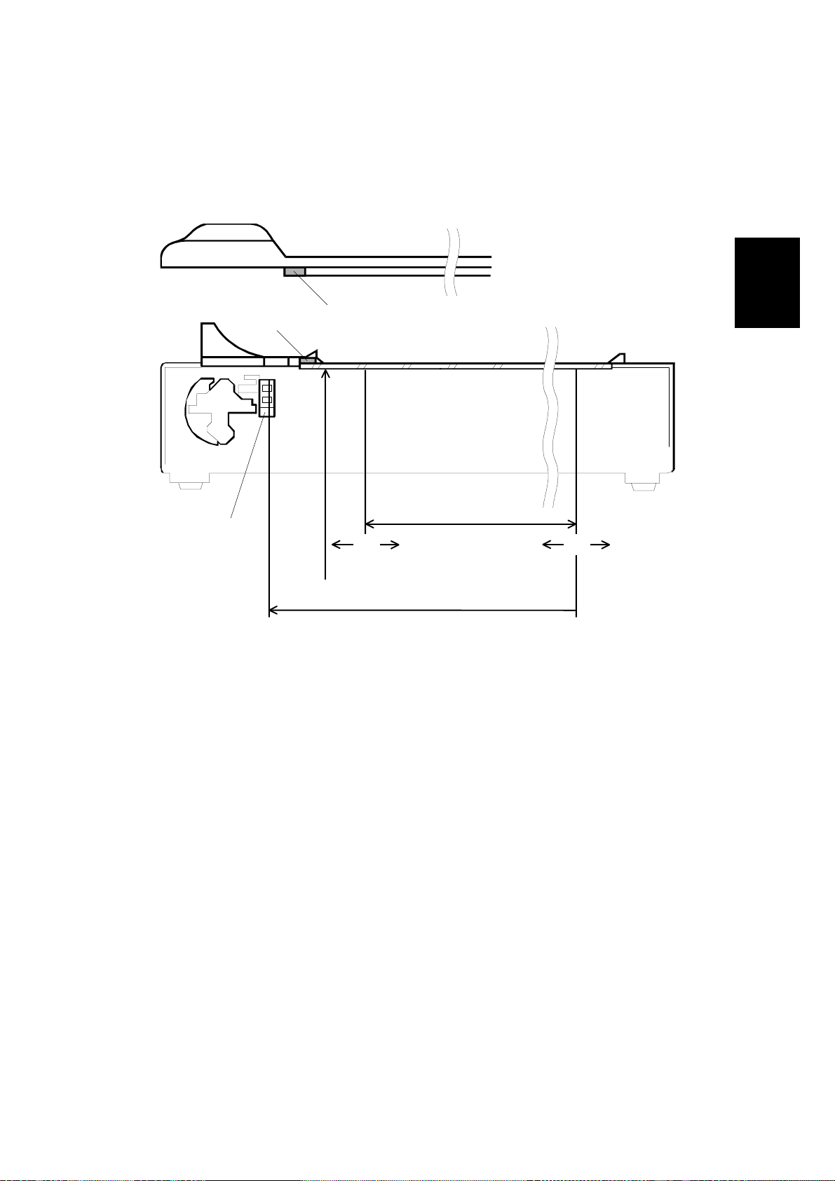
1.1.2 ENDORSER
Number of printable characters: 19 characters (max)
Character set: 43 characters
0123456789#./-:,’AB ····Z
Character size: 1.6 (W) x 2.8 (H) mm
Character pitch:
Printable lines: 1 line (main scan direction)
Inking: Ink roll type
2.4 mm ± 20%
Ink refill: Ink roll exchange
Ink color: Purple
Print position:
a: 7 ± 4 mm
b: 0 ± 5 mm
Document Feed Direction
Document
front side
a
1-2
b
G411V506.WMF
Page 8
22 December 1998 COMPONENT LAYOUT
1.2 COMPONENT LAYOUT
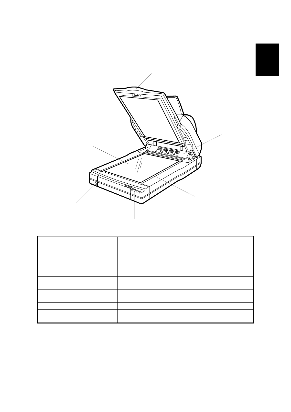
1.2.1 FRONT VIEW
1
2
6
Overall
Information
3
5
4
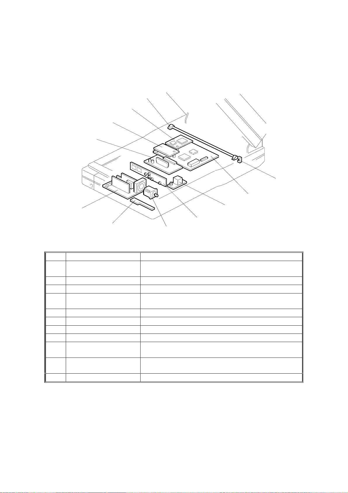
No. Name Function
Platen cover
1
ADF exposure cover
2
Scale Used for positioning a document when placing it on the
3
Scanner indicator lamps T he green and red lights indicate the condition of the
4
5 Power switch Turns the power on and off.
Main exposure glass A document to be scanned in book mode is placed face
6
Covers the document and serves as a neutral
background for documents placed on the main
exposure glass.
Covers the scanner and closes the ADF exposure
cover interlock switch. Also contains an exposure glass.
exposure glass.
scanner.
down on this glass.
G411V500.WMF
1-3
Page 9
COMPONENT LAYOUT 22 December 1998
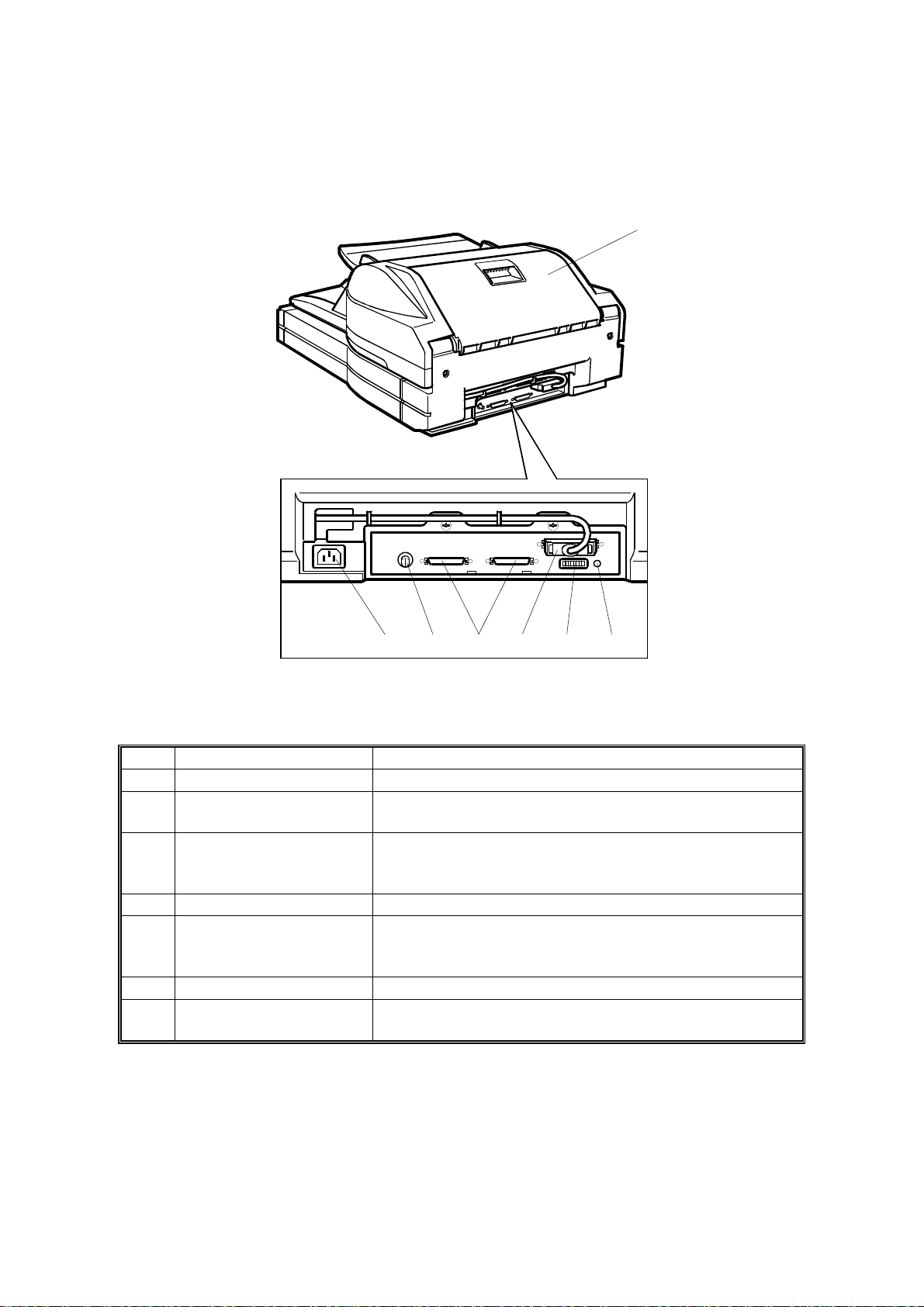
1.2.2 RE AR VIEW
13
101112 789
G411V501.WMF
No. Name Function
7 Reset switch If this is pressed, the machine is reset.
DIP switches
8
Interface for reverse side
9
scanning
(Duplex model only)
10 SCSI connectors For connecting the SCSI cables.
SCSI ID rotary switch
11
12 Power plug inlet For connecting the power cord.
ADF cover Open this cover to clear paper jammed at the input
13
Used to select various scanning modes and test
modes.
Interface for the video signal during reverse side
scanning.
Used to select the SCSI ID and to select diagnostic
tests. Note that positions 8 and 9 are interpreted as
SCSI ID 7.
side.
1-4
Page 10
22 December 1998 COMPONENT LAYOUT
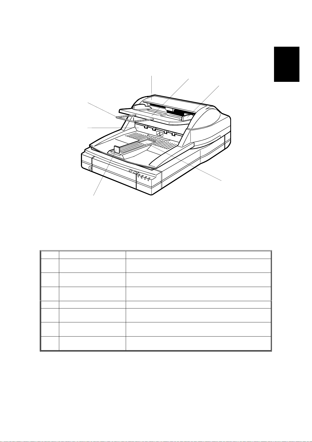
1.2.3 ADF
20
19
18
14
15
G411V502.WMF
Overall
Information
16
17
No. Name Function
ADF Autom atically f eeds multi-page documents into the
14
Document table
15
Document guides Used to properly align the documents placed in the
16
17 Exit table Receives documents fed by the ADF after scanning.
Exit table extension This holds the documents output from the ADF; it can
18
Endorser cover
19
Document support wire If long documents are placed in the input tray, this helps
20
scanner.
Documents to be scanned using the ADF are placed
here.
input tray.
be extended to support long documents.
Open this cover to clean the endorser or replace the
ink.
to feed them correctly.
1-5
Page 11
DRIVE LAYOUT 22 December 1998
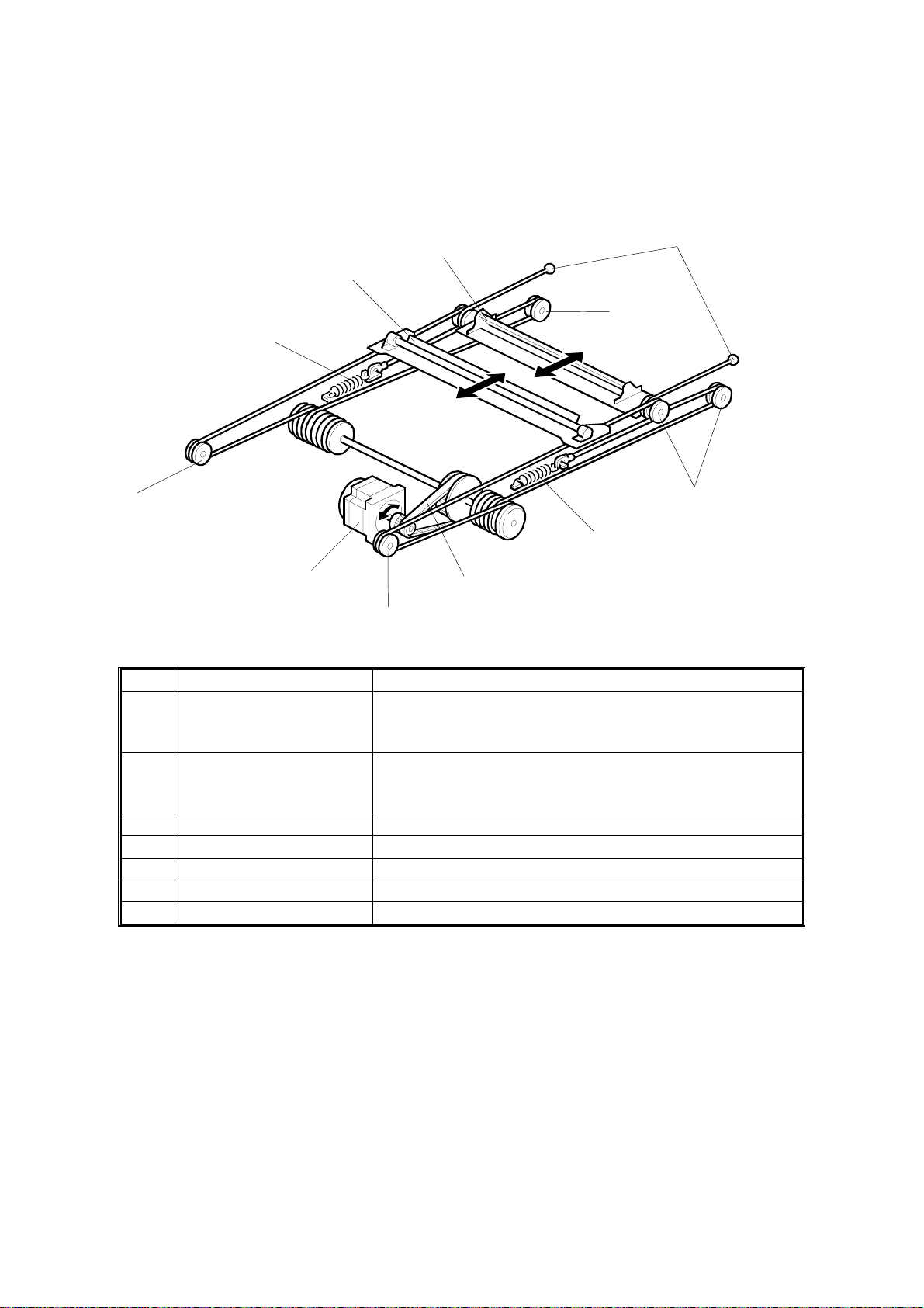
1.3 DRIVE LAYOUT
1.3.1 SCANNER
2
3
1
7
4
7
7
4
6
5
7
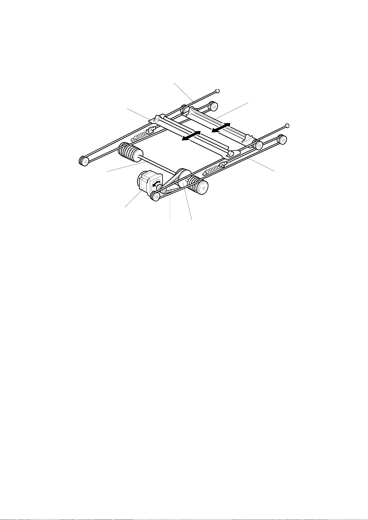
No. Name Function
First scanner Moves the exposure lamp along the document and
1
Second scanner
2
3 Scanner drive wires Transmit motor power to the 1st and 2nd scanners.
4 Wire springs Tighten the scanner drive wires.
5 Motor belt Transmits motor power to the scanner drive wires.
6 Scanner motor Drives the scanners.
7 Pulleys Hold the scanner drive wires.
sends the light reflected from the document to the 2nd
scanner by means of a mirror.
Moves to keep the distance between the exposure lamp
and the CCD constant, and sends light reflected from
the 1st scanner to the CCD.
G411V503.WMF
1-6
Page 12

22 December 1998 DRIVE LAYOUT
1.3.2 ADF
13
14
8
9
Overall
Information
10
11
12
G411V507.WMF
No. Name Function
8 Feed roller Feeds the top page of the original into the ADF.
Pick-up roller
9
Separation roller Stops the lower pages of the original while allowing the
10
White roller
11
(Duplex model only)
12 Feed-out rollers Feed the scanned original onto the exit table.
13 Paper transport drum Transports the original to the scanning position.
14 Paper transport rollers Hold the original against the paper transport drum.
Picks up and transports the top page of the original on
the document table.
top one to pass.
Allows the machine to correct for variations in the white
level of the CIS.
1-7
Page 13
ELECTRICAL COMPONENT LAYOUT 22 December 1998
1.4 ELECTRICAL COMPONENT LAYOUT
1.4.1 SCANNER
11
10
9
8
1
2
7
3
4
6
5
No. Name Function
Home position sensor
1
2 SCU Controls the overall scanner function.
3 Lamp Stabilizer Provides ac power to the exposure lamp.
SBU Cont ains t he CCD, and outputs a video signal to the
4
5 Scanner Motor Drives the scanners.
6 SOP This contains the scanner indicator lamps.
7 PSU Provides dc voltages to the system.
8 IOB Controls the mechanical parts of the scanner.
IPU Board (Option) Performs automatic text/image separation, dynamic
9
RCU
10
(Duplex Model only)
11 Exposure lamp Illuminates the original for exposure.
Detects whether the first scanner is at the home
position.
SCU.
threshold, section area, and document size detection.
Outputs a video signal of the reverse side of the original
to the SCU.
G411V504.WMF
1-8
Page 14
22 December 1998 ELECTRICAL COMPONENT LAYOUT
1.4.2 ADF
23
24
22
25
21
20
26
12
13
19
Overall
Information
14
15
16
17
18
G411V505.WMF
No. Name Function
ADF interlock switch
12
13 Paper transport motor Drives the paper transport drum.
Feed sensor
14
15 Read sensor Synchronizes the original exposure timing.
16 Paper feed motor This drives the pick-up and feed rollers.
CIS (Duplex model only) Contains t he CCDs and LEDs that scan the reverse
17
18 EDU (Option) Controls the mechanical parts of the endorser.
Endorser solenoid
19
(Option)
20 Relay sensor Checks for original misfeeds.
21 Feed-out sensor Detects when a document is at the feed-out position.
Document sensor Detects when a document is placed on the document
22
23 ADU Controls the mechanical parts of the ADF.
Document table position
24
sensor
25 Pick-up clutch Controls pick-up roller rotation.
Document table lift
26
clutch
Detects whether the ADF cover and platen cover are
open or closed; cuts the power supply to the machine.
Detects when a document is just before the feeding
position.
side of the original.
Moves the paper holding plate to hold the original at the
endorser’s printing position.
table.
Detects if the document table is at the feed position or
not.
Switches on to lift the document table up or down.
1-9
Page 15
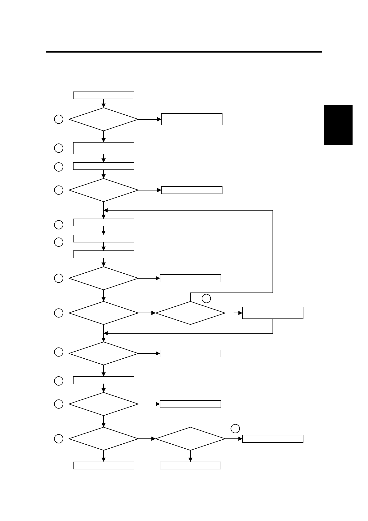
22 December 1998 INITIALIZATION
2. DETAILED SECTION DESCRIPTIONS
2.1 INITIALIZATION
Power on
1
Is the memory OK?
Yes
No
User Level: System error
User Level: System error
Service Level: Memory error
Service Level: Memory error
Detailed
Descriptions
2
3
4
5
6
7
8
Initialize the I/O port, E2PROM,
IPU, and memory controller
Initialize the scanner motor
Is the
home position check
OK?
Yes
Adjust the black level
Turn on the lamp
Scan the white plate
Is the
white level within specified
value?
Yes
Were there any
shading, or lamp, errors?
No
No
No
Yes
Home position error
Lamp error
No
Has the
initialization procedure been
tried three times?
14
Use the default value of the white
Yes
and black levels
10
11
12
9
Endorser motor turns on for 0.1s
one of the feed, read, or feed-
Are the
ADF or the document feeder
cover closed?
Yes
Is any
out sensors on?
No
Is there
any paper on the document
table?
Yes Yes
Detects document
No
Yes
No No
ADF open error
Paper jam
Is the document
table working properly?
READY
2-1
13
Document table error
G411D503.WMF
Page 16

INITIALIZATION 22 December 1998
During power-up initialization, the scanner performs the following steps (refer to the
flow chart on the previous page).
1. Tests the ROM checksum and makes a RAM read/write test. If the CPU cannot
test these, the CPU determines that a memory error has occurred.
2. Initializes the I/O port, E2PROM, and gate arrays (IPU and memory controller).
3. Initializes the scanner motor driver.
4. Checks the home position sensor signal timing while moving the scanners. If
the CPU does not detect a signal change within the specified period, it
determines that a home position error has occurred.
5. Adjusts the difference between the even and odd black levels and total black
level.
6. Turns the exposure lamp on.
7. Adjusts the white level, and checks the peak level of the auto gain control. If the
CPU cannot adjust them to the specified levels, the CPU determines that a
lamp error has occurred.
8. If the black level or the white level cannot be adjusted properly during the
above initialization process, the scanner retries the initialization up to three
times. If the CPU detects an abnormal condition at the third time (step 14), the
CPU stores the default values of the black and white levels into the NVRAM on
the SCU.
9. Checks the ADF interlock switch signal. If the CPU detects that the switch is
open, it determines that an ADF open error has occurred.
10. When the endorser unit has been installed, the endorser moto r turns on for 0.1
second.
11. Checks the signals from the feed, read, and feed-out sensors. If any of them
are on, the CPU determines that there is a paper jam.
12. Checks the document sensor signal. If the CPU detects a document on the
document table, check #13 is not made until the document is removed.
13. Checks the document table position sensor signal timing while lifting and
lowering the document table.
14. See step 8.
2-2
Page 17
22 December 1998 SCANNER MECHANISMS
2.2 SCANNER MECHANISMS
2.2.1 BOOK MODE
Overview
[B][C][A][E]
Detailed
Descriptions
[F] [D]
G411D521.WMF
The exposure lamp (a xenon lamp in this model) [A] illuminates the original. The
image is reflected onto a CCD (charge coupled device) [B] via the 1st, 2nd, and 3rd
mirrors, and through the lens [C].
The 1st scanner [D] consists of the exposure lamp, a reflector [E], and the 1st
mirror [F].
The exposure lamp is energized by an ac supply to avoid uneven light intensity
while the 1st scanner moves in the sub scan direction (down the page). The entire
exposure lamp surface is frosted to ensure even exposure in the main scan
direction (across the page).
The light reflected by the reflector is of almost equal intensity in all directions, to
reduce shadows on pasted originals.
2-3
Page 18
SCANNER MECHANISMS 22 December 1998
Scanner Drive
[G]
[B]
[C]
[F]
[G]
[A]
[D]
[E]
G411D522.WMF
The scanner drive motor [A] (a stepper motor) drives the 1st and 2nd scanners [B,
C] through the timing belt [D], scanner drive pulley [E], scanner drive shaft [F], and
two scanner wires [G].
The IOB board drives the scanner drive motor. The scanning speed depends on
the scanning resolution. The returning speed depends on the distance from the
home position sensor.
2-4
Page 19
22 December 1998 SCANNER MECHANISMS
Basic Scanning Procedure
When the scan command is received from the host computer, the scanner starts
scanning as explained in the following steps.
Initialization
[E]
[A]
[D]
[F]
[G]
[B]
Detailed
Descriptions
[C]
G411D524.WMF
The scanner checks the home position, scanner cover, and memory. If an error is
detected, the scanner motor will stop.
The scanner scans the white plate [A] on the underside of the ADF exposure cover
to perform the shading funct i on.
Image Scanning
The scanner starts to scan the image area at the designated position [B]. The
scanner stops after scanning the designated image area [C]. The arrows indicate
that the scan start position and image area depend on the settings input by the
user.
Scanner Reversing
After the image has been scanned, the scanners return to the home position [D].
The scanners are stopped when the first scanner activates the home position
sensor [E]. If the scanner home position sensor is not activated within a certain
time, a home position sensor erro r will occu r.
2-5
Page 20

SCANNER MECHANISMS 22 December 1998
Optional Steps (Optional IPU Board)
Size Detection
If selected, this is done after the ‘Initialization’ step.
1) Main Scan Direction (Document Width)
The first scanner moves to the book mode standard position ([F] on the previous
page). Then, the scanner scans 5 mm from the book mode standard position.
The scanner determines the document width in the main scan direction from the
output signal level. The edge of the document is detected by the difference
between the level of the document data and the background signal which is
provided by the silver plate [G] attached to the platen cover across the main scan.
If there is a gap at the leading edge, such as a tear (or a black stripe), extending
more than 1 mm across the paper and more than 5 mm down the paper, the
machine cannot detect the document width past this gap. In this case, an error
message may appear, and scanning is impossible. . Disable this feature to allow
the machine to scan this document.
2) Sub Scan Direction (Document Length)
The scanner detects the document size only in the main scan direction, and the
scanner driver determines that the document length is the same as for a standard
paper size of the same width.
NOTE:
The scanner always assumes the paper is in a lengthwise orientation (i.e.,
the main scan is the short side). Also, in USA models, if Letter width is
detected, the paper is always assumed to be Letter size (this means that
the last few inches of a Legal-size original will not be scanned).
Read Size Command
If selected, this is done after the ‘Initialization’ step.
1) Read Size Command
If the scanner receives the Read Size command in book mode, it detects the size
in the main scan direction as described above.
The scanner sends the width data to the host computer.
After detecting the document size, the scanner scans the detected area.
Abort Command
This can occur at any time during the basic scanning procedure.
If the Abort command is received during scanning, the scanner motor is stopped.
Then the scanner returns to the home position ([D] in the previous diagram).
If this command is received while the scanner is reversing or checking the home
position, the operation is not interrupted.
2-6
Page 21
22 December 1998 SCANNER MECHANISMS
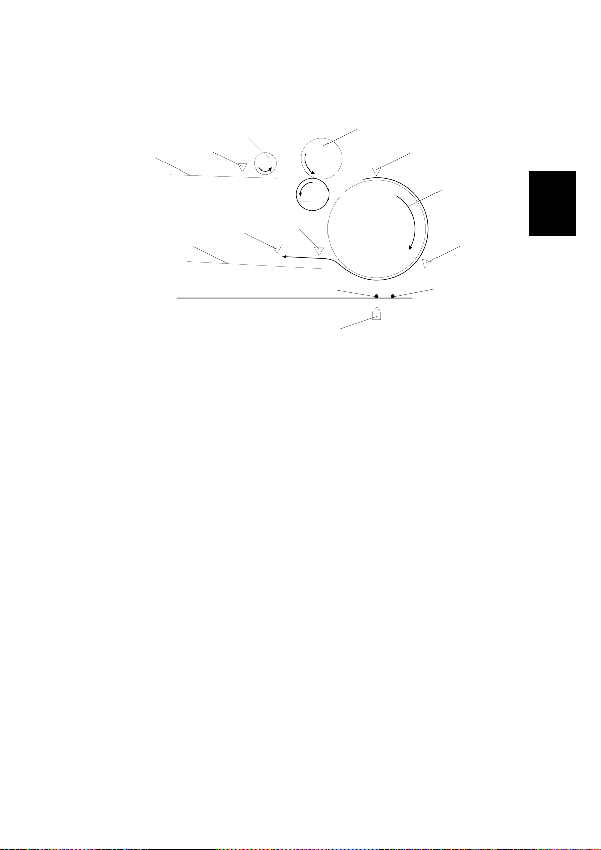
2.2.2 ADF MODE
Overview
[D]
[F]
[G]
[H]
[A]
[N]
[B]
[C]
[M]
[E]
[L]
Detailed
Descriptions
[J]
[K]
G411D517.WMF
[I]
When the originals are pl aced on the do cument table [ A], the document sensor [B]
detects them. The pick-up roller [C] picks up the originals and transports them to
the feed roller [D]. The separation roller [E] turns in the opposite direction to the
feed roller. As a result, just one original is sent to the paper transport drum [G]. The
feed sensor [F] detects whether the original has reached the transport drum or not.
Then the original turns with the transport drum through the read sensor [H]. While
the original passes over the ADF scanning position [J], the scanner [K] reads the
original. After reading, the original goes to the exit table [N]. The feed-out sensor
[M] detects whether the original is fed out or not. The relay sensor [L] detects when
an original is jammed in the area between the read sensor and the feed-out
sensor. This sensor is monitored at all times except when the ADF is feeding a
document.
2-7
Page 22

SCANNER MECHANISMS 22 December 1998
Basic Scanning Procedure
When the scanner receives t he ADF scanning command, the scanner scans the
original as described below.
1) ADF Mode
The scanner performs the home position check and the shading process. If a home
position error is detected, the scanner [K] will stop imme diately. If an ADF cover
open error or memory error is de tec ted, the scanner will stop after returning to the
home position.
The first carriage moves to the ADF scanning position [J] from the scanner home
position [I]. Then the paper transport motor starts.
2) SADF Mode
The scanner waits until the designated time for the originals to be placed on the
document table [A].
When the originals have b een placed on the document table, the sa me procedure
as for ADF mode is carried out.
2-8
Page 23
22 December 1998 SCANNER MECHANISMS
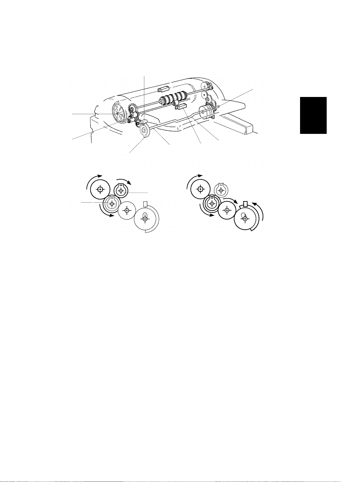
Document Table Lift
[C]
[G]
[F]
Detailed
Descriptions
[A]
[B]
[E]
[H]
[D]
[F]
[A]
G411D518.PCX
The lift mechanism consists of the document table lift clutch [A], the lift shaft [B],
the document table position sensor [C], and the sensor actuator on the gear [D].
In standby mode, the bend in the lift shaft [H] is pointing downwards and the
actuator is just inside the sensor.
When an original is placed on the document table, the document sensor [E] is
activated. Then the paper feed motor [G] turns on. At the same time, the document
table lift clutch [A] turns on to rotate the lift shaft.
At this time, the actuator starts to turn anticlockwise, and the flat part of the spring
[I] that is loosely attached to the bend in the lift shaft pushes up the document table
(see the next page for a diagram).
When the top of the document stack is pushed up against the pi ck-up roller, it can
rise no more. However, the mechanism continues to push up against the tray until
a half-turn of the shaft has been completed (i.e., until the actuator leaves the
document table position sensor). At that time, the document table lift clutch and the
paper feed motor turn off. If the actuator does not leave the sensor within a certain
time, a document table error will occur.
The feed motor turns on again at a motor speed which depends on the scanning
resolution, and the pick-up clutch [F] turns on to feed the top sheet of the original
(see Original Feed and Separation).
2-9
Page 24
SCANNER MECHANISMS 22 December 1998
[I]
[H]
G411D519.WMF
When the first original is being fed, the bend in the lift shaft is pointing up, and the
spring is at maximum compression. As sheets of the document are scanned, the
spring pushes the document table upwards so that the top of the stack is always
against the pick-up roller.
When all page s of the original have been fed out of the ADF, the document table
lift clutch and paper feed motor are energized to lower the tray. They turn off when
the document table sensor is deactivated. If the sensor is not deactivated within the
designated time, a document table error will occur.
2-10
Page 25
22 December 1998 SCANNER MECHANISMS
Original Feed and Separation
[D]
[E]
[F]
[A]
[C]
Detailed
Descriptions
[B]
G411D520.WMF
To feed the original, the paper feed motor and the paper transport motor (which
drives the paper transport drum) turn on. The paper feed motor drives the pick-up
roller [A] through a train of gears and the pick-up clutch [B]. The pick-up clutch
turns on to feed the top sheet of the original. If the pick-up roller feeds multiple
pages of the original, the separation roller [C] and the feed roller [D] separate these
pages (the separation mechanism is friction-based).
When the leading edge of the original ac tivates the feed sensor [E], the paper feed
motor and the pick-up clutch turn off, then the paper transport drum [F] feeds the
original to the scanning position.
Image Scanning
The scanner starts to scan the image when the leading edge has passed the read
sensor by a certain distance (measured by motor pulses).
When the CP U has fed the trailing edge of the original 30 mm past the f eed-out
sensor, the transport motor turns off.
2-11
Page 26

SCANNER MECHANISMS 22 December 1998
Optional Steps
Size Detection
[A]
[B]
[D]
G411D523.WMF
[C]
If selected, this is done after document table lift/paper feed.
1) Main Scan Direction (Document Width)
This function will be available when the optional IPU board is installed.
First of all, the original is fed to the scan ready position between the read sensor
[B] and the size detection position [C]. Then the first scanner moves to the size
detection position [C] from the ADF scanning position [D]. After that, the original is
fed to the ADF scanning position.
As a result of the above operation, the original is fed 5 mm past the first scanner.
Then the CPU detects the original width. The edge of the document is detected by
the difference between the level of the document data and the background level,
which is provided by the black bracket located over the ADF exposure cover.
If there is a gap at the leading edge, such as a tear (or a black stripe), extending
more than 1 mm across the paper and more than 5 mm down the paper, the
machine cannot detect the document width past this gap. In this case, an error
message may appear, and scanning is impossible. Disable this feature to allow the
machine to scan this document.
After finishing the above operation, the first scanner returns to the ADF scanning
position.
2) Sub Scan Direction (Document Length)
The length of the original is calculated by counting the motor pulses while the feed
sensor [A] is on. (The length is detected during scanning.)
2-12
Page 27

22 December 1998 SCANNER MECHANISMS
Read Size Command
If selected, this is done after document table lift/paper feed.
If the scanner receives a Read Size command in ADF mode, it detects the
document size in the main scan direction as described on the previous page.
The scanner sends the width data to the host computer.
Abort and Unload Commands
These can occur at any time during the basic scanning procedure.
When the CP U receives the Abort or the Unload command during paper transport,
the scanner feeds out any original that is in the ADF.
Detailed
Descriptions
2-13
Page 28
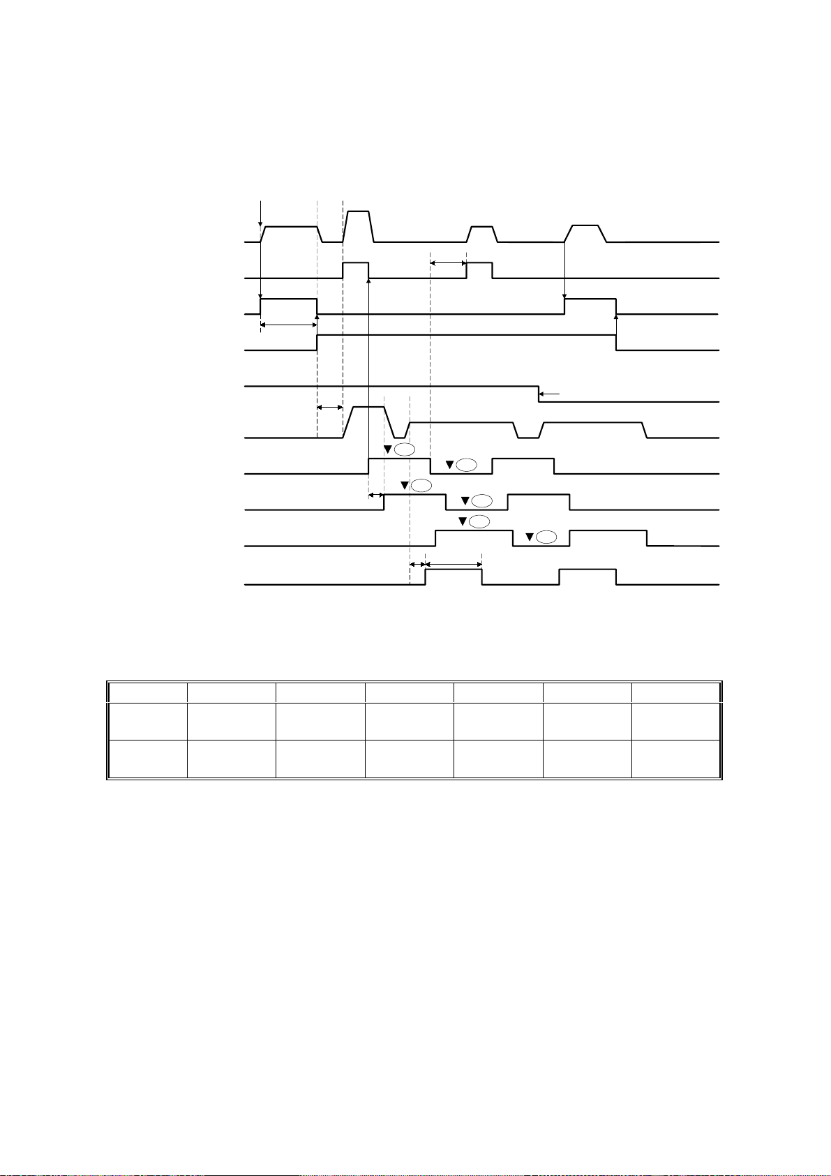
PAPER MISFEED DETECTION 22 December 1998
2.3 PAPER MISFEED DETECTION
Start
MAX
READ
Paper Feed Motor
Pick-up Clutch
OFF
Document Table
Lift Clutch
Document Table
Position Sensor
Document Sensor
MAX
Paper Transport
Motor
Feed Sensor
Read Sensor
Feed-out Sensor
FGATE
FGATE: When this signal is high, scanned data is valid
READ
OFF
t1
t2
t1 t2 t3 t4 t5 t6
200 dpi
400 dpi
Within
3,000
Within
3,000
210 205 44 24.64
210 205 88 172.04
Original End
J1
J4
t3
J2
J5
J3
J6
t5 t6
G411D527.WMF
Unit: milliseconds
L x 0.011
x 200
L x 0.011
x 400
2-14
L: Document length (mm)
Page 29

22 December 1998 PAPER MISFEED DETECTION
J1: The leading edge of the original does not reach the feed sensor within the time
required for feeding the distance between the pick-up roller and the feed sensor
+ 150 mm after the pick-up clutch turned on.
J2: The leading edge of the original does not reach the read sensor within the time
required for feeding the distance between the feed sensor and the read sensor
+ 150 mm after the feed sensor was activated.
J3: The leading edge of the original does not reach the feed-out sensor within the
time required for feeding the distance between the read sensor and the feed
out sensor + 30 mm after the read sensor was activated.
J4: The trailing edge of the original doe s not pass through the feed sensor within
the time required for feeding the maximum original length (2 m) + 60 mm after
the feed sensor was activated.
J5: The trailing edge of the original doe s not pass through the read sensor within
the time required for feeding the original + 75 mm after the read was activated.
J6: The trailing edge of the origin al does not pass through the feed-out sensor
within the time required for feeding the original length + 75 mm after the feedout sensor was activated.
If an original jam or an original non-feed is detected, the paper transport motor,
paper feed motor, and the exposure lamp turn off. Then, the appropriate LEDs
inform the user of the machine’s status.
Detailed
Descriptions
If an original remains in the ADF, the original is fed out and the paper transport
motor stops.
2-15
Page 30
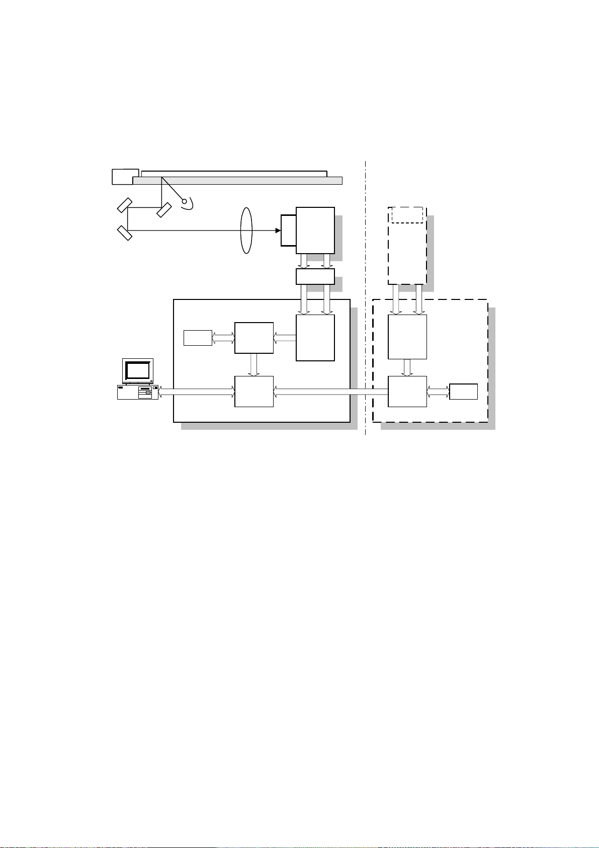
IMAGE PROCESSING 22 December 1998
2.4 IMAGE PROCESSING
2.4.1 OVERVIEW
(Duplex model only)
CCD
SBU
CCD
IOB
CIS
SCU
DRAM
Memory
Control
IC
SCSI
Control
IC
IPU
IPU
Memory
Control
IC
RCU
DRAM
G411D508.WMF
The CCD generates two analog video signals. The SBU (Sensor Board Unit)
converts these analog signals to 8-bit digital signals, then it sends these digital
signals to the SCU (Scanner Control Unit) board through the IOB board. The IPU
(Image Processing Unit) IC on the SCU does the image processing, then the image
data goes to the computer through the Memory Control IC and the SCSI controller.
The CIS (Contact Image Sensor) unit in the duplex model for reverse-side
scanning outputs two digital signals. The IPU on the RCU (Reverse Control Unit)
board does the image processing, then the image data goes to the computer
through the SCU.
2-16
Page 31

22 December 1998 IMAGE PROCESSING
2.4.2 SBU
SBU
SCU
IOB
O
Analog
Processing IC1
A/D 1
8 bit data
IPU
CCD
E
Analog
Processing IC2
A/D 2
8 bit data
G411D507.WMF
The CCD converts the light reflected from the do cument into an analog signal. The
CCD line has 5,000 pixels and the resolution is 400 dpi (15.7 lines/mm).
The CCD has two output lines, for odd and even pixels. Each of these has an
analog processing IC. The analog processing IC performs the following operations
on the signal from the CCD.
1. Z/C (Zero Clamp)
Adjusts the black level reference for even pixels to mach the odd pixels.
Detailed
Descriptions
2. Signal Amplification
Operational amplifiers in the AGC (Auto Gain Control) circuit amplify the analog
signal. The CPU on the SCU board controls the maximum gains of the
operational ampli fiers .
After the above processes, the analog signals are converted to 8-bit digital signals
by the A/D converters. This gives a value for each pixel on a scale of 256 grades.
Then these signals go to the SCU board.
2-17
Page 32

IMAGE PROCESSING 22 December 1998
2.4.3 IPU (IMAGE PROCESSING UNIT)
Overview
Opional
IPU
IPU
C
C
D
Analog
Processing
IC 1
Analog
Processing
IC 2
AD
AD
Odd
8
Even
8
IPU
Selector
8
SCUSBU
8
Memory
Controller
8
SCSI SCSI
G411D505.WMF
The image data from the SBU goes to the IPU IC on the SCU board, which carries
out the following processes on the image data.
1. Auto shading
2. Magnification
3. Mirror processing
4. Filtering (MTF and smoothing)
5. γ (gamma) correction
6. Grayscale processing
7. Binary picture processing
8. Error diffusion
9. Dithering
10. White/black conversion
The image data then goes to the memory controller IC.
2-18
Page 33

22 December 1998 IMAGE PROCESSING
Image processing path
The following image processing is for the scanner (simplex model), not including
the optional IPU. The image processing for each of these units is explained in
separate sections. However, when the optional IPU is installed, the IPU IC on the
SCU only does the shading.
1. Without Optional IPU
SBU
Shading
correction
Magnification/
Mirror Process
2. With Optional IPU
Filtering
SBU
SCU
IPU
correction
γ
SCU
IPU
Shading
correction
Memory
Controller
Dither/
Error Diffusion
Optional
IPU
Binary process
White/black
conversion
G411D500.WMF
Detailed
Descriptions
Shading Correction
The machine scans the white plate opposite the ADF exposure glass to make a
white waveform. Shading correction prevents uneven images caused by
fluctuations in scanned data due to changes in light intensity and CCD sensitivity.
Magnification
Reduction and enlargement in the sub scan direction are done by changing the
scanner motor speed or paper transport motor speed in the ADF. However,
reduction and enlargement in the main scan direction are done by the IPU.
Mirror Processing
A mirror image of the original must be made for output.
Filtering
There are two software filters: the MTF filter and the smoothing filter. The MTF filter
emphasizes sharpness, and is used with text-only documents or documents that
contain text and photo areas. The smoothing filter is used for photo-image
documents.
2-19
Page 34

IMAGE PROCESSING 22 December 1998
Gamma (γγ) Correction
The gamma curve corrects the response of the CCD to grayscales in the original.
Grayscale Processing
This process generates up to 256 image density levels for each pixel.
Dithering
Dither processing produces good quality grayscale images of photo originals.
Error Diffusion
The error diffusion process reduces the difference in contrast between light and
dark areas of a halftone image. Each pixel is corrected using the difference
between it and the surrounding pixels. The corrected pixels are then compared with
a matrix table.
Binary Picture Processing
Each video signal level is converted from 8-bit to 1-bit (black and white image data)
in accordance with a threshold value.
White/Black Conversion
Inverts the image (converts from white to black and vice versa).
After video processing, the data goes to the host computer through the memory
and SCSI controllers.
2-20
Page 35

22 December 1998 REVERSE SIDE SCANNING
2.5 REVERSE SIDE SCANNING
2.5.1 OVERVIEW
[A]
Detailed
Descriptions
[B]
G411D516.WMF
The CIS (Contact Image Sensor) unit [A], which is in the document exit area, scans
the reverse side of the document.
The front side of the document is scanned first. Then the document goes to the
reverse side scanning area. The white roller [B] pushes the document against the
CIS unit for scanning and feeds the document to the exit area.
The position of the CIS unit is fixed in the scanner, and cannot be adjusted in the
field.
2-21
Page 36

REVERSE SIDE SCANNING 22 December 1998
2.5.2 CIS (CONTACT IMAGE SENSOR) UNIT
[A]
[B]
[D]
[C]
G411D513.WMF
[C]
G411D528.WMF
The CIS unit consists of the LED array (68 chips/line x 2 lines) [A], rod lens array
[B], five CCDs [C], and the CIS drive board [D] (this contains the CCD drive circuit,
analog processing circuit, A/D converter, shading correction IC, and LED drive
circuit). The CIS unit scans 4800 pixels in the main scan direction at a resolution of
400 dpi (15.7 lines/mm).
There is a row of LEDs on each side of the CCD so that the light is of almost equal
intensity in all directions. This reduces shadows at the edges of documents.
The five CCDs are arranged as shown above (viewed from directly above the
original feed path). The CCDs have dummy pixels at the ends, so to get a
continuous scan across the page, the CCDs have to overlap. However, as a result,
a continuous line cannot be scanned across the page at the same time. Data is
held in memory and combined later.
In book mode when scanning the front side, the scanner may stop if the buffer fills
up. This may happen if the data is complex. Scanning may not start again in
exactly the same place, due to mechanical inaccuracies. This is not a big problem
when scanning the front side. However, for the reverse side, because a complete
scan line is not scanned at the same time, it could mean loss of data.
Because of this, reverse side scanning is only enabled at 6 reproduction ratios
(expressed in the driver as dpi: 100, 200, 300, 400, 500, and 600 dpi). This is
because there is not enough memory to buffer the data and calculate the pixels for
the resulting image at other resolutions without stopping the scanner.
2-22
Page 37

22 December 1998 REVERSE SIDE SCANNING
2.5.3 IMAGE SCANNING
Analog
Processing
Circuit
Analog
Processing
Circuit
C
L
E
D
C
D
Analog
Processing
Circuit
Analog
Processing
Circuit
Analog
Processing
Circuit
AD
AD
AD
AD
AD
Shading
Correction
Odd
Even
CIS
8
8
RCU
IPU
RCU
8
Memory
Controller
SCU
SCSI SCSI
8
G411D504.WMF
Detailed
Descriptions
CIS
Shading
correction
Magnification/
Mirror Process
Filtering
correction
γ
IPU
Error Diffusion
Dither/
Binary Process
Memory
Controller
White/black
conversion
G411D526.WMF
As explained on the previous page, the CIS unit contains five CCDs. The analog
signal from each CCD goes to an analog processing IC. The function of the analog
processing circuit is the same as for the SBU. After this, the analog signal is
converted to a digital signal by the A/D converter. Then, the data goes to the
shading circuit for correction. After shading, the data is divided to two signals: Odd
and Even. Then, these go to the IPU on the RCU board.
The RCU board contains the IPU and memory controller ICs for image processing.
The image processing in the IPU is the same as for the IPU in the SCU except for
the shading correction.
After image processing, the data goes to the PC through the SCSI controller on the
SCU.
2-23
Page 38

ENDORSER UNIT 22 December 1998
2.6 ENDORSER UNIT
2.6.1 OVERVIEW
[D]
[B]
G411D516.WMF
[A]
[C]
[D]
[A]
G411D514.WMF
The endorser unit [A] is located just before the exit roller [B]. The endorser unit
prints up to 19 characters (which are input using the scanner driver) at the trailing
edge of the document.
The endorser operates as follows.
1. The user inputs characters and enables the endorser function using the
scanner driver.
2. The scanner operates in the normal ADF mode.
3. The paper transport motor stops at a certain time after the leading edge of the
paper passes through the feed-out sensor.
4. The endorser motor turns on.
5. The endorser solenoid [C] is energized and the paper holding plate [D] goes
down to hold the original.
6. The endorser prints the characters.
7. After printing, the endorser motor turns off.
8. The endorser solenoid is de-energized and the paper holding plate goes up to
release the original.
9. The paper transport motor turns on ag ai n, and the original is fed to the original
tray.
2-24
Page 39

22 December 1998 ENDO RSER UNI T
2.6.2 ENDORSER UNIT
[D]
[C]
[F]
[E]
[A]
[B]
G411D515.WMF
The endorser unit consists of the endorser motor [A], clutch [B], character belt [C],
hammer unit [D], and ink roller [E].
Detailed
Descriptions
The endorser motor drives the character belt and hammer unit and operates the
hammer [F].
The clutch controls the print timing.
The ink roller always contacts the character belt and always supplies ink to the belt.
When the ink is used up, the customer replaces only t he ink roller.
2-25
Page 40

LOW POWER MODE 22 December 1998
2.7 LOW POWER MODE
W
15 min.
12 W
t
Operation Stand-by mode Low power mode
G411D525.WMF
When the scanner has been idle for 15 minutes (this interval cannot be adjusted),
the scanner automatically enters low power mode. However, the scanner cannot
enter low power mode when a document jam or system error exists.
NOTE:
The scanner can enter low power mode if the ADF cover and/or platen
cover is open or paper remains on the document table.
When the scanner enters low power mode, the PSU cuts the +24 V, +12 V, –12 V
and +5 Vs supplies, and continues to supply +5VE only. As a result, the scanner
consumes less than 12 W. The operation panel indicates that the machine is in low
power mode with the following LEDs.
LED Status
Power on Blinking
Machine busy Off
Document in place Off
Error Off
The scanner returns to stand-by mode when the ADF cover and/or platen cover is
opened and closed, or when the user places a document on the document table, or
when a Read command is received from the computer.
2-26
Page 41

22 December 1998 MAIN PCBS AND THEIR FUNCTIONS
2.8 MAIN PCBs AND THEIR FUNCTIONS
2.8.1 BOARD STRUCTURE
Endorser Unit
CIS Unit
RCU
SCU
ADU
IOB
Clutches
Sensors
Motors
SBU
Operation
Panel
Scanner
Motor
H.P Sensor
Lamp
Stabilizer
ADF
Main
Frame
Exposure
Lamp
Detailed
Descriptions
Optional IPU
PSU
Cooling
Fan
G411D509.WMF
For the main function of each PCB, refer to the Electrical Component Layout
section.
2-27
Page 42

MAIN PCBS AND THEIR FUNCTIONS 22 December 1998
2.8.2 SCU (SCANNER CONTROL UNIT)
Optional IPU RCU
SCU
Odd
Even
IOB
SEL
Memory
Controller
OSC
SCSI
Controller
SCSI 1SCSI 2
EPROM
4 Mbit (x16)
IPU
OSC
SRAM
256 kbit (x8)
Image data Signal line
E2PROM
2 kbit
Reset IC
CPU Bus
DRAM
16 Mbit (x16)
CPU
OSC
EIO
SCSI
Terminator
DIP SW
SCSI ID
Rotary
SW
G411D512.WMF
This is the main board. The functions of each component are as follows.
CPU: HD6413002F
•
Scanner sequence control
•
Clock/timer control
•
DMA control
IPU (Image Processing Unit):
•
Shading correction
•
Image processing (Mirror image, reproduction ratios, MTF correction, binary
picture processing, edge extraction, and so on)
Memory Controller:
•
Stores the image data from the IPU in the memory (DRAM 32 Mbytes x 2).
•
Address contro l whe n re calling the data from the memory.
SCSI controller: SCSI interface controller.
SRAM: Work area (32 kbytes)
EPROM: Contains the program.
Enhanced I/O (EIO):
•
Extension for the I/O port.
•
DIP switches (mode selection), rotary switches (SCSI ID setting), and a push
switch (reset button) are connected.
E2PROM: Holds the book, ADF, and lamp counter values.
2-28
Page 43

22 December 1998 MAIN PCBS AND THEIR FUNCTIONS
2.8.3 IOB (INPUT/OUTPUT BOARD)
IOB
SBU
PSU
Interlock
Switch
SCU
+ 5V
+ 12V
+ 24V
+ 24V ADU
Scanner
Motor Driver
Driver
Driver
Driver
Scanner
Motor
H.P Sensor
Lamp
Stabilizer
Exposure Lamp
Operation
Panel
ADU
Detailed
Descriptions
G411D510.WMF
The IOB contains the drive circuits for the scanner motor and the exposure lamp.
The control signals such as drive and rotation direction, and drive current for the
scanner motor come from the SCU. Also, the control signal for the exposure lamp
comes from the SCU.
The image signals from the SBU go through this board to the SCU.
2-29
Page 44

MAIN PCBS AND THEIR FUNCTIONS 22 December 1998
2.8.4 ADU (ADF DRIVE UNIT)
ADU
Motor Driver
Paper
Transport
Motor
IOB
+ 5V
+ 24V ADU
+ 12V
- 12V
+ 24V ADU
+ 5V
+ 5V
+ 12V
- 12V
+ 15V
Motor Driver
Paper
Feed
Motor
Clutches
Sensors
EDU
CIS Unit
G411D511.WMF
The ADU drives the motors and clutches in the ADF unit. Also, it informs the
sensor status to the SCU.
The SCU generates the control signals for each electrical component and the
endorser, then these are sent to the ADU through the IOB. The drivers on the ADU
convert the control signals into drive pulses for the motors.
2-30
Page 45

22 December 1998 ENVIRONMENT
3. INSTALLATION
3.1 ENVIRONMENT
3.1.1 PRECAUTIONS
Please observe the following precautions in order to ensure safe operation of the
scanner and to realize its full performance.
• Ambient illumination must be less than 2,000 lux (do not expose to direct
sunlight).
• Do not use the scanner in any location that is exposed to frequent vibration.
• Do not expose the scanner to dusty or corrosive atmospheric conditions.
• Ensure that the area in which the scanner is used is well ventilated (30
m3/hr/person).
• Make sure that the surface on which you place the scanner is stable and level.
3.1.2 ENVIRONMENTAL CONDITIONS
Installation
Temperature: 10°C to 32°C (50 to 90°F)
Humidity: 20 to 80 %
3.1.3 MACHINE LEVEL
1. Front to back: Within 5 mm (0.2") of level
2. Right to left: Within 5 mm (0.2") of level
3.1.4 MINIMUM SPACE REQUIREMENTS
Place the scanner near a power source, providing clearance as shown.
A: 10 mm (0.2") B: 30 mm (1.2") C: 600 mm (23.7")
A
D
CB
G411I500.WMF
3-1
Page 46

SCANNER INSTALLATION 22 December 1998
3.1.5 POWER REQUIREMENTS
CAUTION
1. Be sure to ground the scanner.
2. Make sure the plug is firmly inserted in the outlet.
3. Avoid multi-wiring.
1. Input voltage level:
• 102 to 138 V ac (45 to 65 Hz)
• 187 to 276 V ac (45 to 65 Hz)
2. Permissible voltage fluctuation: ± 10%
3.2 SCANNER INSTALLATION
Please refer to the scanner user’s manual for details.
3.3 IPU UNIT INSTALLATION
Please refer to the scanner user’s manual for details.
3-2
Page 47

22 December 1998 ENDORSER UNIT INSTALLATION
3.4 ENDORSER UNIT INSTALLATION
3.4.1 ACCESSORY CHECK
Check the quantity and condition of the accessories in the box against the following
list:
Description Q’ty
1. Endorser Unit ......................................................................... 1
2. Solenoid Ass’y........................................................................ 1
3. EDU Board ............................................................................. 1
4. Harness.................................................................................. 1
5. Ink Roller ................................................................................ 1
6. Decal...................................................................................... 1
7. Screw - M3 x 6 ....................................................................... 2
8. Card Spacer ........................................................................... 1
9. Installation Procedure............................................................. 1
Installation
3-3
Page 48

ENDORSER UNIT INSTALLATION 22 December 1998
3.4.2 INSTALLATION PROCEDURE
1. Open the ADF cover [A]. Remove the
ADF upper cover [B] (2 screws), ADF
right cover [C] (1 screw), and the
endorser cover [D].
NOTE:
Remove the right cover by
carefully lifting it from the rear.
2. Install the spacer [E] and the EDU
board [F] (2 screws).
[C]
[B]
[A]
[D]
G514I501.WMF
[F]
3. Route the cable [G] as shown.
NOTE:
Ensure that the end of the
cable with the large connector
[H] is toward the inside of the
machine.
3-4
[H]
[G]
[E]
G514I502.WMF
G514I503.WMF
Page 49

22 December 1998 ENDORSER UNIT INSTALLATION
4. Install the solenoid assembly [I] as
shown (3 screws).
G514I504.WMF
[K]
5. Install the clamp [J] and connect the
[L]
three cables [K] to the EDU board [L].
[I]
Installation
6. Install the core [M].
7. Open the platen cover. Install the
endorser unit [N], as shown (1
connector).
8. Attach the decal [O].
[J]
[M]
G514I505.WMF
[O]
[N]
9. Reinstall the endorser, right, and upper covers.
3-5
G514I506.WMF
Page 50

ENDORSER UNIT INSTALLATION 22 December 1998
3.4.3 STAMP DENSITY ADJUSTMENT PROCEDURE
1. Open the ADF cover [A]. Remove the
ADF upper cover [B] (2 screws), ADF
right cover [C] (1 screw), and the
endorser cover [D].
NOTE:
Remove the right cover by
carefully lifting it from the rear.
2. Remove the solenoid assembly screw
[E] from the hole [F] and replace it in
hole [G]. Do not tighten the screw yet.
3. Loosen the screw [H] and adjust the
height of the bracket [I].
NOTE:
To reduce the stamp density,
raise the bracket. To increase
the density, lower the bracket.
[C]
[B]
[A]
[D]
G514I501.WMF
[F]
[I]
[G]
4. Tighten the assembly screw [E] to
secure the bracket in the new position.
5. Reinstall the endorser, right, and upper
covers.
[H]
[E]
G514I507.WMF
3-6
Page 51

22 December 1998 RED LAMP UNIT INSTALLATION
3.5 RED LAMP UNIT INSTALLATION
3.5.1 ACCESSORY CHECK
Check the quantity and condition of the accessories in the box against the following
list:
Description Q’ty
1. Exposure Lamp ...................................................................... 1
2. Installation Procedure............................................................. 1
Installation
3-7
Page 52

RED LAMP UNIT INSTALLATION 22 December 1998
3.5.2 INSTALLATION PROCEDURE
1. Remove the rear cover [A] (3 screws).
[A]
G514I500.WMF
2. Remove the stopper brackets [B].
3. Remove the pins [C].
[B]
[C]
[B]
G514I510.WMF
3-8
Page 53

22 December 1998 RED LAMP UNIT INSTALLATION
[D]
4. Open the platen cover and remove
the lamp cover [D] (2 screws).
G514I508.WMF
Installation
5. Remove the exposure lamp [E] (1
[E]
screw).
G514I509.WMF
6. Install the red lamp (1 screw, 1 connector) in the place of the exposure lamp.
7. Reinstall the lamp cover, the pins, the stopper brackets, and the rear cover.
3-9
Page 54

22 December 1998 DIP SWITCH SETTINGS
4. SERVICE LEVEL FUNCTIONS
4.1 DIP SWITCH SETTINGS
The factory default position of the dip switches is indicated in the diagram below.
After changing a dip switch setting, either switch the power off and then on again,
or press the reset switch.
OFF
1234 6758
ON
G411M500.WMF
Dip Switch Setting Table
Dip Switch Item Contents
SCAM function
switch
1234 6758
ON
SCSI synchronous
transfer switch
1234 6758
ON
Internal SCSI
terminator switch
1234 6758
ON
Do not adjust switch 4. This is for factory use only.
Service level test modes
Various tests for the scanner are carried out using dip switches 5 to 8.
Within each test mode, tests are selected by turning the SCSI ID rotary
switch, and the machine's condition is indicated by the four LEDs on the
covers.
ON
1234 6758
Note the position of the SCSI ID rotary switch before you change it.
To return to normal operation mode after testing, switch dip switches 5 to 8
all off, return the SCSI ID rotary switch to its operating position, then press
the reset button.
Demonstration mode
1234 6758
ON
OFF: SCAM function enabled
ON: SCAM function disabled
OFF: SCSI synchronous transfer enabled
ON: SCSI synchronous transfer disabled
OFF: Internal SCSI terminator on
ON: Internal SCSI terminator off
Scanner demonstration in book and ADF modes;
Refer to Table A later in this section.
ON
Tables
Service
Component test
mode
1234 6758
ON
Sensor test mode Each sensor can be tested; refer to Table C later in
1234 6758
ON
Self diagnostic mode Results of the diagnosis are indicated through a
1234 6758
ON
Each component can be tested; refer to Table B later
in this section.
this section.
combination of the LEDs on the covers; refer to Table
D later in this section and “Troubleshooting” in
section 6.
4-1
Page 55

DIP SWITCH SETTINGS 22 December 1998
g
y
Dip Switch Item Contents
ADF counter
indication
1234 6758
ON
Book mode counter
indication
1234 6758
ON
Exposure lamp on
time indication
1234 6758
ON
CIS on time
indication
1234 6758
ON
The number of pages scanned in ADF mode is
indicated throu
h a combination of the SCSI ID rotar
switch position and the LEDs; refer to Table E later in
this section.
(Unit = 1 sheet, Max. value = 2,500k sheets)
The number of pages scanned in book mode is
indicated in the same way as described above for
ADF mode; refer to Table E later in this section.
(Unit = 1 sheet, Max. value = 1,000k sheets)
The total illumination time of the lamp is indicated in
the same way as above.
(Unit = 1 hour, Max. value = 3,000 hours)
The total illumination time of the CIS is indicated in
the same way as above.
ADF counter
indication
1234 6758
ON
(Reverse side)
Endorser character
counter indication
1234 6758
ON
The number of pages scanned in ADF mode is
indicated in the same way as above.
(Unit = 1 sheet, Max. value = 2500 k sheets)
The number of endorser characters is indicated in the
same way as above.
Counter reset mode After the dip switches are set to on, and the Start
button is held down for more than 3 seconds, all
LEDs are turned off, all counters which are stored in
2
PROM are cleared.
1234 6758
ON
the E
(These counters are the ADF mode, book mode,
exposure lamp, CIS and endorser character
counters.)
NOTE:
If you change the position of the SCSI ID rotary switch during these tests,
be sure to put it back to the original position after you have finished.
Table A: Demonstration Mode
SCSI ID Rotary Switch No. Contents
0 200 dpi scan in book mode
1 400 dpi scan in book mode
2 200 dpi scan in ADF mode
3 400 dpi scan in ADF mode
4 200 dpi scan in endorser mode
5 400 dpi scan in endorser mode
6 200 dpi scan in duplex mode
7 400 dpi scan in duplex mode
8ADF free run *
9 Not used
1
*1: The scanner drives the ADF without any documents.
NOTE:
During the demonstration, the LEDs indicate the machine status as usual.
But if an error occurs during the demonstration (e.g. mis-feed, jam, etc.),
the scanner stops, and the LEDs indicate the error condition.
4-2
Page 56

22 December 1998 DIP SWITCH SETTINGS
Table B: Component Test Mode
SCSI ID Rotary Switch No. Contents
0 All components off
1 Exposure lamp on/off *
2 Document table lift clutch on/off *
3 Pick-up clutch on/off *
4 CIS LEDs on/off *
5 Endorser solenoid *
1
1
1
1
1
6 Cooling fan motor on/off
7 Not used
8 Not used
9 Not used
*1: When the Start button is pressed to start the test, the component turns on and
off repeatedly.
Table C: Sensor Test Mode
SCSI ID Rotary Switch No. Contents
0 Home position sensor
1 Read sensor
2 Document table position sensor
3 Document sensor
4 ADF cover interlock switch
5 Feed sensor
6 Feed-out sensor
7 Relay sensor
8 Not used
9 Not used
If the selected sensor is on, all LEDs turn on. If the selected sensor is off, all LEDs
turn off.
Tables
Service
4-3
Page 57

DIP SWITCH SETTINGS 22 December 1998
Table D: Self Diagnostic Mode
During the self-diagnostic mode, the scanner performs the following tests.
1) Home position error check
2) Exposure lamp error check
3) White level error check
4) Document table error check
5) SCU error check
6) RCU error check
7) IPU error check
8) CIS LEDs error check
9) Memory error check
If the scanner detects errors, the first error that occurred is indicated by a
combination of four LEDs.
LEDs
Error Items
SCU error Blinking — — Blinking
RCU error Blinking — On Blinking
IPU error Blinking On — Blinking
Home position error Blinking Blinking Blinking On
Exposure lamp error Blinking Blinking On On
White level error Blinking Blinking — —
CIS Leds error Blinking Blinking On Blinking
Memory error (Simplex) Blinking — — —
Memory error (Duplex) — Blinking — —
Power On
(Green)
Machine
Busy (Green)
Document in
Place (Green)
Error
(Red)
On: LED on Blinking: LED blinking —: LED off
Table E: Counter Indication Mode
Rotary Switch Table
SCSI ID Rotary Switch No. Contents
0 Not used
1Units
2 Tens
3 Hundreds
4 Thousands
5 Ten thousands
6 Hundred thousands
7 Millions
8 Not used
9 Not used
4-4
Page 58

22 December 1998 DIP SWITCH SETTINGS
LED Indication Table
LEDs
Counter Value
0————
1———On
2——On—
3——OnOn
4—On——
5—On—On
6 — On On —
7 — On On On
8On———
9On——On
Power On
(Green)
Machine Busy
(Green)
Document in
Place (Green)
Error
(Red)
On: LED on —: LED off
Use the rotary switch to select a digit of the counter. The value of the selected digit
is indicated by a combination of the four LEDs. For the LEDs, “ON” represents a 1
and “OFF” represents a 0. The four LEDs are read off as a four-bit number.
Example:
Rotary switch no LED condition
1 (units) (ON, OFF, OFF, OFF) = 1000 = 8
2 (tens) (OFF, OFF, ON, ON) = 0011 = 3
3 (hundreds) (OFF, ON, OFF, ON) = 0101 = 5
4 to 7 (OFF, OFF, OFF, OFF) = 0000
>>> Total counter value = 538 sheets
Tables
Service
4-5
Page 59

LEDS/TEST POINTS 22 December 1998
4.2 LEDs/TEST POINTS
4.2.1 LEDs
SCU/LEDs
Number Monitored Signal
LED1 +5VS
LED2 +5VE
LED3 CPU clock
4.2.2 TEST POINTS
ADU
Number Monitored Signal
TP301 +24 V
TP302 –12 V
TP303 +12 V
TP304 COM
TP305 +5VE
TP308 +5VS
TP309 COM
4.3 SPECIAL TOOLS
Part Number Part Name
A0069104 Scanner Positioning Pin (4 pcs/set)
G4049003 RS-13 Chart (A5)
G4049005 RS-13 Chart (A4)
G4049004 RS-13 Chart (A3, 55 kg)
G4049006 RS-13 Chart (A3, 90 kg)
H2039114 RS-12 Chart (A3)
4-6
Page 60

22 December 1998 COVERS
5. REPLACEMENT AND ADJUSTMENT
CAUTION
Before starting disassembly, be sure to turn off the main switch and
disconnect the power cord and interface cable(s) for safety.
5.1 COVERS
5.1.1 ADF EXTERIOR
[B]
[A]
[D]
G411R500.WMF
1. Open the ADF cover [A].
2. Remove the ADF upper cover [B] (2 screws).
3. Remove the ADF right cover [C] (1 screw).
NOTE: Remove the ADF right cover by carefully lifting it from the rear.
4. Remove the ADF left cover [D] (1 screw).
[C]
Adjustment
Replacement
5-1
Page 61

COVERS 22 December 1998
5.1.2 ADF COVER
[A]
[B]
G411R501.WMF
G411R502.WMF
1. Remove the ADF upper and ADF right cover (see ADF Exterior).
2. Remove the rear cover (see Scanner Exterior/Operation Panel).
3. Open the platen cover vertically (see Exposure Glass).
4. Remove the spring [A].
5. Remove the pin [B] (1 screw).
6. Remove the ADF cover [C] (1 connector).
[C]
5-2
Page 62

22 December 1998 COVERS
5.1.3 SCANNER EXTERIOR/OPERATION PANEL
[C]
[B]
[D]
[A]
G411R503.WMF
1. Remove the operation panel [A] (1 screw).
2. Remove the front cover [B] (3 screws).
3. Remove the left cover [C] (2 screws).
4. Remove the right cover [D] (2 screws).
5. Remove the rear cover [E] (3 screws).
G411R504.WMF
[E]
Adjustment
Replacement
5-3
Page 63

ADF AND UPPER SIDE 22 December 1998
5.2 ADF AND UPPER SIDE
5.2.1 DOCUMENT SENSOR
[A]
G411R505.WMF
1. Remove the ADF upper cover (see ADF Exterior).
2. Remove the document sensor [A] (1 connector, 2 screws).
5.2.2 SEP ARATION UNIT
[A]
G411R506.WMF
1. Remove the ADF upper, ADF left, and ADF right cover (see ADF Exterior).
2. Remove the separation unit [A] (3 connectors, 4 screws).
5-4
Page 64

22 December 1998 ADF AND UPPER SIDE
5.2.3 DOCUMENT TABLE ASSEMBLY
[A]
G411R507.WMF
1. Remove the separation unit (See Separation Unit).
2. Remove the document table assembly [A] (3 screws).
5.2.4 CIS
[B]
[A]
Adjustment
Replacement
G411R508.WMF
1. Remove the document table assembly (See Document Table Assembly).
2. Remove the stopper bracket [A] (1 screw).
3. Remove the ADU (See ADU/Paper Transport Motor).
4. Remove the CIS [B] (2 connectors, 1 screw).
5-5
Page 65

ADF AND UPPER SIDE 22 December 1998
5.2.5 SCANNING GUIDE PLATE
[A]
G411R509.WMF
1. Remove the ADF upper, ADF left, and ADF right cover (See ADF Exterior).
2. Remove the scanning guide plate [A] (2 screws).
5.2.6 FEED SENSOR
[C]
[A]
[B]
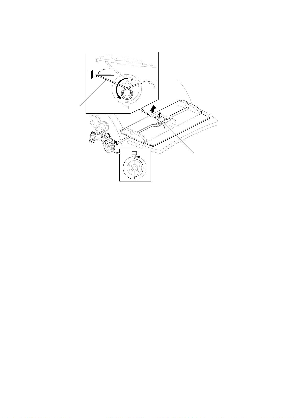
G411R510.WMF
1. Open the ADF cover [A].
2. Remove the feed cover [B] (2 screws).
3. Remove the feed sensor [C] (1 connector, 1 screw).
5-6
Page 66

22 December 1998 ADF AND UPPER SIDE
5.2.7 RE AD SENSOR
[A]
G411R511.WMF
1. Remove the rear cover (See Scanner Exterior/Operation Panel).
2. Remove the read sensor [A] (1 connector, 1 screw).
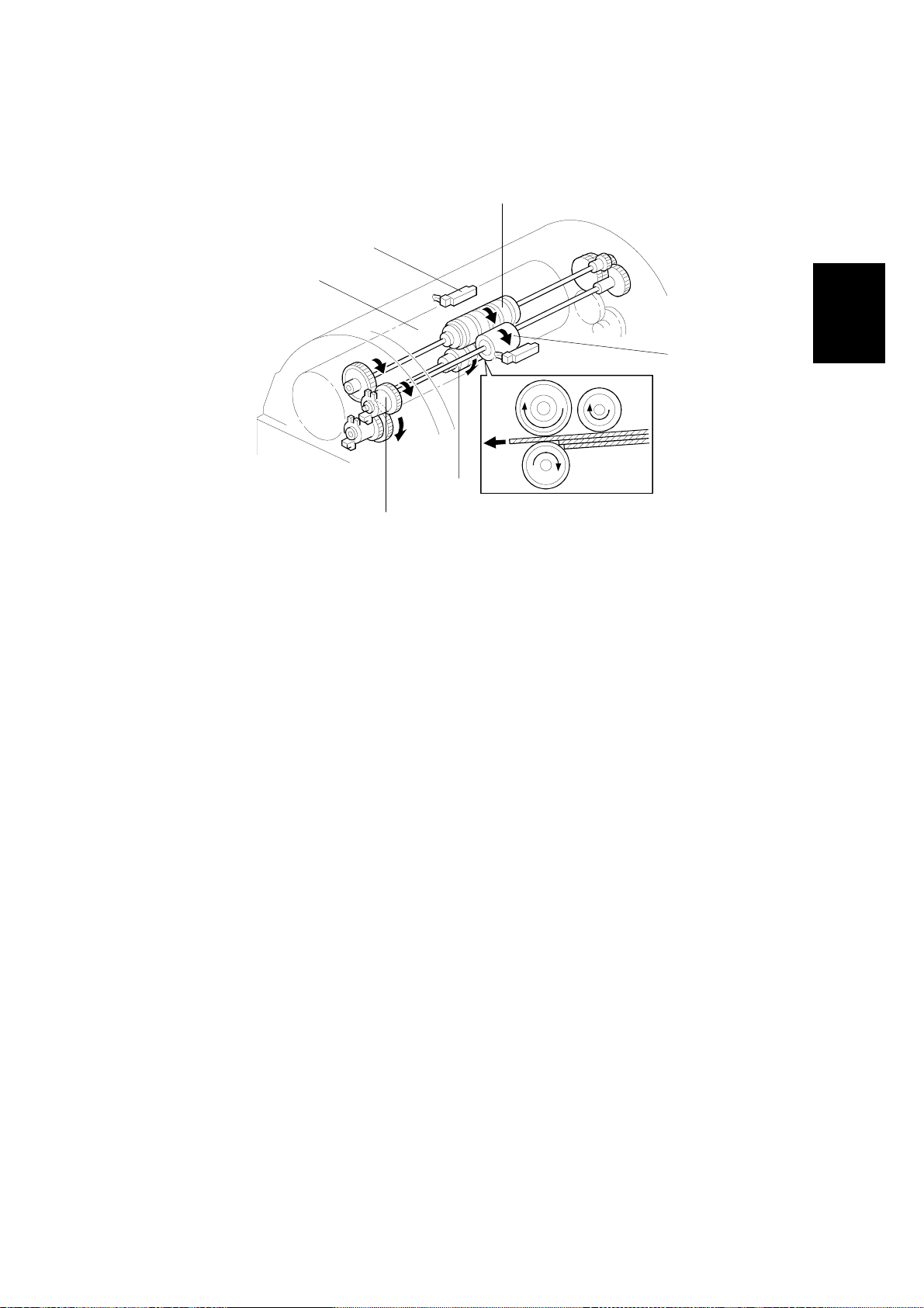
5.2.8 FEED-OUT SENSOR
[B]
[A]
Adjustment
Replacement
G411R512.WMF
1. Remove the feed-out cover [A] (2 screws).
2. Remove the feed-out sensor [B] (1 connector, 1 screw).
5-7
Page 67

ADF AND UPPER SIDE 22 December 1998
5.2.9 P APER TRANSPORT DRUM
[A]
[B]
G411R513.WMF
[D]
[C]
G411R515.WMF
1. Remove the separation unit (see Separation Unit).
2. Remove the paper feed motor (see Paper Feed Motor).
3. Remove the ADU (see ADU/Paper Transport Motor).
4. Remove the pape r transport motor (see ADU/Paper Transport Motor).
5. Remove the registration guide plate [A] (1 connector, 2 screws).
G411R514.WMF
6. Remove the rear cover (see Scanner Exterior/Operation Panel).
7. Remove the stopper brackets [B] (1 screw each).
8. Remove the pins [C].
9. Open the ADF cover.
10. Remove the paper transport drum [D] (2 E-rings, 2 bearings).
5-8
Page 68

22 December 1998 ADF AND RIGHT SIDE
5.3 ADF AND RIGHT SIDE
5.3.1 PAPER FEED MOTOR
[A]
G411R516.WMF
1. Remove the ADF upper and ADF right cover (see ADF Exterior).
2. Remove the paper feed motor [A] (1 connector, 3 screws).
5.3.2 EDU
[A]
G411R517.WMF
Adjustment
Replacement
1. Remove the ADF upper and ADF right cover (see ADF Exterior).
2. Remove the EDU [A] (3 connectors, 2 screws).
5-9
Page 69

ADF AND RIGHT SIDE 22 December 1998
5.3.3 ENDORSER SOLENOID
[A]
G411R518.WMF
1. Remove the ADF upper and ADF right cover (see ADF Exterior).
2. Remove the endorser solenoid [A] (1 connector, 3 screws).
5.3.4 RELAY SENSOR
[A]
G411R519.WMF
1. Remove the ADF upper and ADF right cover (see ADF Exterior).
2. Remove the relay sensor [A] (1 connector, 1 screw).
5-10
Page 70

22 December 1998 ADF AND LEFT SIDE
5.4 ADF AND LEFT SIDE
5.4.1 ADU/PAPER TRANSPORT MOTOR
[B]
[A]
G411R520.WMF
1. Remove the ADF upper and ADF left cover (see ADF Exterior).
2. Remove the ADU [A] (10 connectors, 3 screws).
3. Remove the paper transport motor [B] (1 connector, 3 screws).
5.4.2 DOCUMENT TABLE POSITION SENSOR
[A]
Adjustment
Replacement
G411R521.WMF
1. Remove the ADF upper and ADF left cover (see ADF Exterior).
2. Remove the document table position sensor [A] (1 connector, 1 screw).
5-11
Page 71

ADF AND LEFT SIDE 22 December 1998
5.4.3 PICK-UP CLUTCH/DOCUMENT TABLE LIFT CLUTCH
[C]
[A]
[B]
G411R522.WMF
1. Remove the ADF upper and ADF left cover (see ADF Exterior).
2. Remove the stopper bracket [A] (2 screws).
3. Remove the pick-up clutch [B] (1 connector).
4. Remove the document table lift clutch [C] (1 connector, 1 E-ring).
5-12
Page 72

22 December 1998 SCANNER
5.5 SCANNER
5.5.1 EXPOSURE GLASS
[A]
[B]
[E]
G411R514.WMF
1. Remove the rear cover (See Scanner Exterior/Operation Panel).
[C]
[D]
G411R523.WMF
Adjustment
Replacement
2. Remove the stopper brackets [A] (2 screws).
3. Remove the pins [B].
4. Open the platen cover vertically.
5. Remove the lamp cover [C] (2 screws).
6. Remove the scale [D] (3 screws).
7. Remove the exposure glass [E].
5-13
Page 73

SCANNER 22 December 1998
5.5.2 EXPOSURE LAMP
[B]
[A]
G411R524.WMF
1. Remove the exposure glass (see Exposure Glass).
2. Slide the 1st scanner to the cutout [A] in the right frame.
3. Remove the exposure lamp [B] (1 connector, 1 screw).
5-14
Page 74

22 December 1998 SCANNER
5.5.3 SBU/LAMP STABILIZER/SCANNER MOTOR/PSU
[A]
[C]
[B]
[D]
G411R525.WMF
G411R526.WMF
[E]
[F]
G411R527.WMF G411R528.WMF
1. Remove the exposure glass (see Exposure Glass).
2. Remove the lens cover [A] (4 screws).
3. Disconnect the flexible cable [B]
4. Remove the SBU [C] (4 screws).
5. Remove the lamp stabilizer [D] (2 connectors).
Adjustment
Replacement
6. Remove the operation panel (see Scanner Exterior/Operation Panel).
7. Remove the front cover (see Scanner Exterior/Operation Panel).
8. Remove the scanner motor [E] (1 spring, 1 connector, 2 screws).
9. Remove the PSU [F] (5 connectors, 2 screws).
5-15
Page 75

SCANNER 22 December 1998
5.5.4 IOB
[A]
[B]
G411R529.WMF
1. Remove the exposure glass (see Exposure Glass).
2. Remove the lens cover (see SBU/Lamp Stabilizer/Scanner Motor/PSU).
3. Remove the PCB cover [A] (6 screws).
4. Remove the IOB [B] (5 connectors, 4 screws).
5-16
Page 76

22 December 1998 SCANNER
5.5.5 SOP
[A]
G411R538.WMF
1. Remove the operation panel and the front cover (see Scanner
Exterior/Operation Panel).
2. Remove the SOP (1 connector).
5.5.6 HOME POSITION SENSOR
[A]
Adjustment
Replacement
G411R530.WMF
1. Remove the right cover (see Scanner Exterior/Operation Panel).
2. Remove the home position sensor [A] (1 connector, 1 screw).
5-17
Page 77

SCANNER 22 December 1998
5.5.7 ADF INTERLOCK SWITCH
[A]
G411R531.WMF
1. Remove the rear cover (see Scanner Exterior/Operation Panel).
2. Remove the ADF interlock switch [A] (1 connector, 1 screw).
5-18
Page 78

22 December 1998 SCANNER
5.5.8 SCANNER WIRE
[B]
G411R532.WMF
[A]
[C]
[D]
G411R534.WMF
1. Remove the exposure glass (see Exposure Glass).
G411R533.WMF
Adjustment
Replacement
2. Remove the stopper brackets [A] (1 screw each).
3. Remove the ADF [B] (4 connectors, 4 screws).
4. Remove the operation panel, front cover, right cover, and left cover (see
Scanner Exterior/Operation Panel).
5. Remove the left frame [C] (11 screws).
6. Remove the right frame [D] (11 screws).
5-19
Page 79

SCANNER 22 December 1998
[A]
[F]
[B]
[E]
[D][C]
G411R536.WMF
7. Remove the right and left scanner wire brackets [A] (1 screw each). Then,
remove the 1st scanner.
8. Remove the tension spring [B].
9. Loosen the screw [C] securing the wire tension bracket [D].
10. Remove the scanner wire [E].
11. Secure the 2nd scanner with the scanner positioning tools (P/N A0069104) [F].
12. Wind the new scanner wire around the scanner drive pulley in the correct
direction, as shown (
).
13. Wind the end of the new wire with the ball as shown ().
14. Wind the end of the new wire with the ring as shown (, and ).
15. Wind the new scanner wire for the other side as well.
16. Install the tension spring [B] on the wire tension bracket [D].
17. Tighten the wire tension bracket [D].
5-20
Page 80

22 December 1998 SCANNER
[H]
[G]
G411R535.WMF
18. Install the 1st scanner and adjust its position with the scanner positioning tools
(P/N A0069104) [G].
19. Secure the 1st scanner with the scanner wire bracket [H] (1 screw each).
20. Remove the positioning tools. After sliding the scanner to the front and back
several times, set the positioning tools to check the scanner wire bracket and
tension bracket again.
21. Reassemble the scanner.
Adjustment
Replacement
5-21
Page 81

PCB 22 December 1998
5.6 PCB
5.6.1 SCU/RCU/IPU
[C]
[B]
[A]
1. Remove the SCU assembly [A] (2 screws).
2. Remove the RCU [B] (3 screws).
3. Remove the IPU [C] (1 screw).
NOTE:
When replacing the SCU, put the old ROM (IC31) on the new SCU.
G411R537.WMF
5-22
Page 82

22 December 1998 SELF-DIAGNOSTICS
6. TROUBLESHOOTING
6.1 SELF-DIAGNOSTICS
The scanner automatically performs a series of self-diagnostic checks each time
the power is turned on. If an error is detected, it is displays the type of error using
the four LEDs on the scanner. See “Detailed Section Descriptions - Initialization”
for more details of the initialization procedure.
6.2 CHECK ITEMS
6.2.1 ITEMS CHECKED DURING INITIALIZATION
The self-diagnostics check the following items at power-up.
1) The ADF or ADF cover is not closed properly.
2) An original is jammed in the ADF.
3) There is a problem with the operation of the document table.
4) Memory error (system error)
Does the memory in the scanner work properly?
5) Home position error (system error)
Have the scanners reached home position properly?
6) Exposure lam p error (system error)
Is the standard white level detected properly?
NOTE:
• If an error is detected for any of items 4) to 6), “System Error” is
indicated, and the details can be checked with the self-diagnostics (see
section 6-3).
• Even if an error is detected for item 2), scanning can start in book mode.
Trouble-
shooting
6-1
Page 83

ERROR INDICATION 22 December 1998
6.3 ERROR INDICATION
If the self-diagnostics find an error, the error is displayed by a combination of the
four LEDs on the scanner. If the dip switches on the rear of the machine are set up
for normal operation, the error is indicated roughly for users. When the dip switches
are set to the self-diagnostic mode position, the system error is indicated in detail
for technicians.
6.3.1 USER LEVEL ERROR INDICATION
Conditions Contents
Machine
Initialization
Demonstration
Mode
Stand-by
User-visible
Error Conditions
System Error Blinking Blinking Blinking Blinking
Overall
machine check
Scan wait
mode
ADF cover switch open On Off Off On
Document jam On Off Blinking On
Document misfeed On Off On On
Document table error On Off Blinking Blinking
Endorser error Blinking Blinking On Off
Originals on
the table
No On Off Off OffNormal mode
Yes On Off On Off
No On Off Blinking Off
Yes On Off Blinking Off
No On On Off OffScanning Normal mode
Yes OnOnOnOff
On: LED on Blinking: LED blinking Off: LED off
Green Green Green Red
On On On On
On On On On
LEDs
6.3.2 TECHNICIAN LEVEL ERROR INDICATION
Error Items
Memory error (Simplex) Blinking Off Off Off
Memory error (Duplex) Off Blinking Off Off
Exposure lamp failure Blinking Blinking On On
CIS error Blinking Blinking On Blinking
White level error Blinking Blink ing Off Of f
Home position error Blinking Blinking Blinking On
SCU error Blinking Off Off Blinking
RCU error Blinking Off On Blinking
Optional IPU error Blinking On Off Blinking
On: LED on Blinking: LED blinking Off: LED off
Green Green Green Red
LEDs
6-2
Page 84

22 December 1998 TROUBLESHOOTING PROCEDURES
6.4 TROUBLESHOOTING PROCEDURES
There are two types of troubleshooting procedure.
•
For user-visible error conditions that the user could not clear up
•
For technician level error conditions
6.4.1 USER-VISIBLE ERROR CONDITIONS
ADF Interlock Switch Open
Symptom:
The problem cannot be solved with the procedures in the user’s manual.
Possible Causes:
•
Defective ADF interlock switch
•
Damaged cable between the ADF interlock switch and the PSU
Procedure:
Does 24 volts come to the ADF cover interlock switch?
Yes No
Is the cable damaged?
Yes No
Replace the PSU.
Replace the cable.
Replace the ADF interlock switch.
Trouble-
shooting
6-3
Page 85

TROUBLESHOOTING PROCEDURES 22 December 1998
Document Jam
Symptom:
The problem cannot be solved with the procedures in the user’s manual.
Possible Causes:
•
Dama ged separation unit
•
Damaged paper transport drum assy
•
Damaged paper feed-out unit
•
Defective paper transport motor or paper feed motor
•
Defective read sensor or feed-out sensor
•
Defective SCU, IOB or ADU
Procedure:
First of all, check the sensors with demonstration and sensor check mode. See
Service Level Functions – Dip Switch Settings.
Are all the sensors OK?
Yes No
Is the cable damaged?
Yes No
Replace the sensor.
Replace the cable.
Does the jam always happen at the same position?
Yes No
Are the 24-volt lines from the PSU to the IOB (24VADU) or from
the IOB to the ADF OK?
Yes No
Is the cable damaged?
Yes No
Replace the PSU.
Replace the cable.
Is the 24-volt line from the ADU to the paper transport motor OK?
Yes No
Is the cable damaged?
Yes No
Replace the ADU.
Replace the cable.
Replace the paper transport motor.
NOTE:
Did the jam occur at the paper transport drum assy?
Yes No
Replace the paper feed-out assy.
Replace the paper transport drum assy.
If the feed motor is defective, a “Document Table Error” is
generated.
6-4
Page 86

22 December 1998 TROUBLESHOOTING PROCEDURES
Paper Misfeed
Symptom:
The problem cannot be solved with the procedures in the user's manual.
Possible Causes:
•
Dama ged separation unit
•
Defective pick-up clutch
•
Defective ADU
•
Defective SCU
•
Defective feed sensor
Procedure:
Does the pick-up roller mechanism work?
Yes No
Is 24 volts supplied to the pick-up clutch?
Yes No
Is the cable damaged?
Yes No
Replace the ADU.
Replace the cable.
Is there an open circuit in the clutch?
Yes No
Replace the SCU.
Replace the pick-up clutch.
Does the jam happen at the separation unit?
Yes No
Replace the pick-up roller.
Replace the separation unit.
6-5
Trouble-
shooting
Page 87

TROUBLESHOOTING PROCEDURES 22 December 1998
Document Table Error
Symptom:
The problem cannot be solved with the procedures in the user's manual.
Possible Causes:
•
Defective document table position sensor
•
Defective document table clutch
•
Defective paper feed motor
•
Defective ADU
•
Defective SCU
•
Damaged document table
Procedure:
Is the document table itself OK?
Yes No
Replace it.
Does the table work (up/down operation)?
Yes No
Does the separation roller mechanism work?
Yes No
Does 24 volts come to the paper feed motor?
Yes No
Is the cable damaged?
Yes No
Replace the ADU.
If the 24 volts from the PSU
is defective, another error
will be generated.
Replace the cable.
Replace the motor, if it has a defective.
Does the document table lift clutch work.
Yes No
Does 24 volts come to the document table lift clutch?
Yes No
Is the cable damaged?
Yes No
Replace the ADU
Replace the cable.
Replace the document table lift clutch
Check the table lift mechanism.
Replace the SCU.
NOTE:
If the 5-volt line is defective, the ADF LEDs will not work, so the error type
will not be visible. Therefore it can be assumed that there is a problem with
a timing signal. All timing signals are generated in the SCU and the
problem can be fixed by replacing the SCU.
6-6
Page 88

22 December 1998 TROUBLESHOOTING PROCEDURES
Endorser Error
Symptom:
The problem cannot be solved with the procedures in the user's manual.
Possible Causes:
•
Defective endorser unit
•
Defective EDU
Procedure:
Is the endorser unit is broken?
Yes No
Is the cable between the EDU and the endorser unit or the ADU
and the EDU OK?
Yes No
Replace the cable.
Replace the EDU.
Replace the endorser unit.
6-7
Trouble-
shooting
Page 89

TROUBLESHOOTING PROCEDURES 22 December 1998
6.4.2 SERVICE CALL ERRORS (SYSTEM ERRORS)
If a system error occurs, the following errors can be detected with the selfdiagnostics using the dip switches. See Service Level Functions – Dip Switch
Settings.
Memory Error
Symptom:
This error occurs in the following conditions .
•
SRAM read/write error
•
DRAM read/write error
•
Memory over run error
Possible Cause:
•
Defective SCU
Procedure:
Replace the SCU.
6-8
Page 90

22 December 1998 TROUBLESHOOTING PROCEDURES
Lamp Error
Symptom:
The white level cannot be adjusted.
Possible Cause:
•
A mirror is out of position.
•
Misalignment
•
Defective SBU
•
Defective IOB
•
Defective SCU
Procedure:
Does the exposure lamp light during scanning?
Yes No
Does 24 volts come to the lamp stabilizer?
Yes No
Is the cable damaged?
Yes No
Replace the PSU.
Replace the cable.
Replace the exposure lamp
Does the exposure lamp light?
Yes No
Replace the lamp stabilizer.
Go to the next step.
Are all mirrors installed properly?
Yes No
Reseat any mirrors that are out of place.
Does the SBU generate the correct signals?
Yes No
Replace the SBU.
Replace the SCU. If that does not work, try changing the IOB.
Trouble-
shooting
Document Table Error
Same as for the user-visible error condition. See section 6-4-1.
6-9
Page 91

TROUBLESHOOTING PROCEDURES 22 December 1998
CIS Error (duplex model only)
Symptom:
The white level of the reverse side scanning cannot be adjusted.
Possible Cause:
•
Defective CIS unit
•
Defective ADU
•
Defective RCU
•
Defective SCU
Procedure:
Does the LED array light?
YES No
Does 15 volts come to the CIS unit?
Yes No
Is the cable damaged?
Yes No
Replace the ADU.
Replace the cable.
Replace the CIS unit.
Does the CIS generate the correct signals?
Yes No
Replace the CIS unit.
Does the RCU generate the correct signals?
Yes No
Replace the RCU.
Replace the SCU.
6-10
Page 92

22 December 1998 TROUBLESHOOTING PROCEDURES
Shading Error
Symptoms:
A shading error occurs when one of the following conditions occurs.
•
The difference in black level cannot be adjusted.
•
The black level cannot be adjusted.
•
The white level cannot be adjusted.
Possible Causes:
•
A mirror is out of position.
•
Misalignment
•
Defective SCU
•
Defective SBU
•
Defective exposure lamp
•
Dirty white plate
Procedure:
Is there any problem with the exposure lamp?
Yes No
Is the white plate dirty?
Yes No
Are all the mirrors installed properly?
Yes No
Reseat the mirror.
Does the SBU generate the correct signals?
Yes No
Replace the optical unit.
Replace the SCU.
Replace the ADF exposure cover.
Replace the exposure lamp.
NOTE:
The read signal goes to the SCU through the IOB, but the IOB does not do
any image processing. Therefor e the IOB pr ob a bly does not have a
problem. However, if the problem is not solved even after replacing the
SCU, try changing the IOB.
Trouble-
shooting
6-11
Page 93

TROUBLESHOOTING PROCEDURES 22 December 1998
Home Position Error
Symptom:
This error is detected when the home position sensor cannot detect the first
scanner.
Possible Causes:
•
Defective scanner motor
•
Damaged cable between the scanner motor and the IOB
•
Defective IOB
•
Defective home position sensor
•
Damaged cable between the home position sensor and the IOB
Procedure:
Does the home position sensor work? Check it with sensor test mode. (See See
Service Level Functions – Dip Switch Settings.)
Yes No
Does 5 volts reach the sensor?
Yes No
Is the cable between the home position sensor
and the IOB OK?
Yes No
Replace the cable.
Replace the PSU.
Replace the sensor.
Is the drive wire OK?
Yes No
Replace it.
Does 24 volts reach the scanner motor?
Yes No
Is the cable between the motor and the IOB damaged?
Yes No
Replace the IOB.
Replace the cable.
Replace the scanner motor.
6-12
Page 94

22 December 1998 TROUBLESHOOTING PROCEDURES
SCU Error
Symptom:
3.3 volts generated on the SCU failed during scanning.
Possible Cause:
•
Defective SCU
Procedure:
Replace the SCU.
RCU Error
Symptom:
3.3 volts generated on the RCU failed during scanning.
Possible Cause:
•
Defective RCU
Procedure:
Replace the RCU.
Optional IPU Error
Symptom:
3.3 volts generated on the optional IPU board failed during scanning.
Possible Cause:
•
Defective optional IPU board
Procedure:
Replace the optional IPU board.
Trouble-
shooting
6-13
Page 95

INDICATION WHEN A CONNECTOR IS OUT OF POSITION 22 December 1998
6.5 INDICATION WHEN A CONNECTOR IS OUT OF
POSITION
6.5.1 SCANNER
SCU
1
2
3
4
Connector
1 (CN201) — — — —
2 (CN203) On Off On Off
3 (CN204) On Off Blinking Blinking Document table error
4 (CN210)
5 (CN209) — — — —
6 (CN211) On Off Off On ADF interlock switch open
7 (CN208) — — — —
8 (CN206)
9 Not used Not used Not used Not used
10 (CN202) Blinking Blinking Blinking Blinking System error
11 (CN205)
Green Green Green Red
Blinking Blinking Blinking Blinking
Blinking Blinking Blinking Blinking
Blinking Blinking Blinking Blinking
Scanner LEDs
IOB
6 8
5
7 9
11
10
G411T500.WMF
Remarks
System error
System error
System error
On: LED on Off: LED off Blinking: LED blinking
—: When the machine is switched on, all LEDs should light briefly. However, “—” in
these tables indicates that the LED does not light up briefly at power-up.
6-14
Page 96

22 December 1998 INDICATION WHEN A CONNECTOR IS OUT OF POSITION
6.5.2 ADF
Document Sensor
13
Document Table Position
Sensor
12
10
9
Feed-out Sensor
14
15
G411T501.WMF
Remarks
Connector
Pick-up Clutch
Document Table Lift
Clutch
11
1
2
3
ADU
4
Green Green Green Red
5 6 87
Scanner LEDs
1 (CN303) On Off Off Of f
2 (CN302) On Off Blinking Blinking Document table error
3 (CN301) On Off On Off
4 (CN306) On Off Off Of f
5 (CN305) On Off Off Of f
6 (CN307) On Off Blinking Blinking Document table error
7 (CN310) On Off Off Of f
8 (CN308) On Off Off Of f
9 (CN309) On Off Off Of f
10 (CN304) On Off Blink ing Blinking Document table error
11 On Of f Blinking Blinking Document table error
12 On Off Off Off
13 On Off On Off
14 On Of f Blinking Blinking Document table error
15 On Off Off Off
Trouble-
shooting
On: LED on Off: LED off Blinking: LED blinking
—: When the machine is switched on, all LEDs should light briefly. However, “—” in
these tables indicates that the LED does not light up briefly at power-up.
6-15
Page 97

BLOWN FUSE CODITIONS 22 December 1998
6.6 BLOWN FUSE CODITIONS
Fuse
Power Supply Unit
FU1 5 A/125 V 3.15 A/250 V No response.
FU31 4 A/125 V
FU32 4 A/125 V
FU33 5 A/125 V No response.
FU35 5 A/125 V
ADU (Duplex Model)
FU101 1.25 A/250 V CIS error
EDU
FU401 3.15 A/250 V
Lamp Stabilizer
FU1 1 A/60 V Exposure lamp err or
115 V 220 ~ 240 V
Rating Symptom when turning on the main switch
Exposure lamp error
Home position error
White level error
Document table working error
Document jam
Exposure lamp error
RCU error
Endorser error
Endorser does not work.
6-16
Page 98

22 December 1998 IPU (IMAGE PROCESSING UNIT)
7. OPTION
7.1 IPU (IMAGE PROCESSING UNIT)
7.1.1 OVERVIEW
The IPU does the following.
Dynamic Threshold
This function automatically determines a suitable threshold value based on the
original, and converts the scanned image to binary data.
Auto Photo/Letter
This function automatically identifies the text portions of an original and the
photographic portions, and scans each in a suitable scan mode.
Document Size Detection
This function automatically detects the width of an original, and sends the
information to the host computer.
Section Area
This function selects an area within an original and sets scanning conditions for
that area.
Option
7-1
Page 99

IMAGE PROCESSING PATH 22 December 1998
γ
7.2 IMAGE PROCESSING PATH
The following image processing is for the scanner with the optional IPU.
SCU
IPU
Size
Detection
Grayscale
Filtering
Dynamic Threshold
Magnification/
Mirror Process
correction
Optional
IPU
Auto Photo/Letter
Section
Binary
Processing
Dynamic
Threshold
Sparation
Area
White/Black
conversion
Binary
Filtering
SCUOptional IPU
Memory
Controller
G411O500.WMF
A suitable threshold value is determined based on the original.
Auto Photo/Letter Separation
Generally, text areas have strong contrast between the image and the background.
In photo areas, mid-range gray areas are common. By using these characteristics,
the original image is separated into text and photo areas.
Section Area
The original image is separated into specified areas. Each area is processed using
the specified scanning mode.
Size Detection
See Detailed Section Descriptions – Scanner Processes.
7-2
Page 100

1234567891011
HS2P (G407/G408/G410/G411) Point to Point Diagram
A
GND
GND
GND
SDO7
GND
SDO6
GND
SDO5
GND
SDO4
GND
SDO3
GND
SDO2
GND
SDO1
GND
SDO0
GND
SDE7
GND
SDE6
GND
SDE5
GND
SDE4
GND
SDE3
GND
SDE2
FG
B
FG
CN101
1
GND
2
GND
3
GND
4
GND
5
GND
6
GND
7
GND
8
C
D
GND
9
GND
10
GND
11
GND
12
NC
13
NC
14
NC
15
GND
16
GND
17
GND
18
GND
19
GND
20
GND
21
GND
22
GND
23
GND
24
GND
25
GND
26
DB0
27
DB1
SCSI I/F
28
DB2
29
DB3
30
DB4
31
DB5
32
DB6
33
DB7
34
DB8
35
GND
36
GND
37
NC
38
TERMPWR
39
NC
40
GND
41
XATN
42
GND
43
XBSY
44
XACK
45
XRST
46
XMSC
47
XSEL
48
XC/D
49
XRED
50
XI/D
E
F
OIPUB
(Option)
G
H
A1A2A3A4A5A6A7A8A9
CN1
A1A2A3A4A5A6A7A8A9
CN502
GND
123456789
CN501
123456789
CN105
GND
CN102.38Pin
CN104
CN701
1
2
3
4
5
6
7
8
9
10
11
12
13
14
15
16
17
18
19
20
21
22
23
24
25
26
27
28
29
30
31
32
33
34
35
36
37
38
39
40
41
42
43
44
45
46
47
48
49
50
51
52
53
54
55
56
57
58
59
60
61
62
63
64
65
66
67
68
FG
OVCLK
XOLGATE
XR3VDTCT
FU1
1
2
3
4
5
6
7
8
9
10
11
12
13
14
15
16
17
18
19
20
21
22
23
24
25
26
27
28
29
30
31
32
33
34
35
36
37
38
39
40
41
42
43
44
45
46
47
48
49
50
51
52
53
54
55
56
57
58
59
60
61
62
63
64
65
66
67
68
A11
A10
A12
A13
A14
A15
A16
A17
A18
A19
A20
A21
A22
A23
A11
A10
A12
A13
A14
A15
A16
A17
A18
A19
A20
A21
A22
A23
1011121314151617181920212223242526272829303132333435363738394041424344454647484950515253545556575859606162636465666768697071727374757677787980
1011121314151617181920212223242526272829303132333435363738394041424344454647484950515253545556575859606162636465666768697071727374757677787980
A(0)
A(2)
A(4)
A(6)
DMAD8
DMAD10
DMAD12
DMAD14
DREQ
XDWR
GND
XCSRCU
XHMR
XHWRN
XRESET
A(8)
A(10)
A(18)
RVSEL
5VE
GND
GND
5VE
5VE
XAWKD(1)
XAWKD(3)
XAWKD(5)
XAWKD(7)
XAWFGT
XALG
GND
XARCLK
GND
XARLSYNC
XARKD(1)
XARKD(3)
XARKD(5)
XARKD(7)
GND
XCSOIPU
XRESET
A(1)
A(3)
A(5)
A(7)
A(9)
A(11)
D(9)
D(11)
D(13)
D(15)
XDIPUINST
GND
GND
GND
GND
5VE
5VE
XAWKD(0)
XAWKD(2)
XAWKD(4)
XAWKD(6)
XAWLSYNC
GND
XAWCLK
GND
XARLGT
XARFGT
XARKD(0)
XARKD(2)
XARKD(4)
XARKD(6)
XINT OIPU
XHWR
XRD
A(0)
A(2)
A(4)
A(6)
A(8)
A(10)
D(8)
D(10)
D(12)
D(14)
XC3VDTCT
GND
GND
GND
CN102
Same as
CN101
SCSI I/F
123456789
CN106
GND
A24
A25
A26
A27
A28
A29
A30
A24
A25
A26
A27
A28
A29
A30
D(8)
GND
D(10)
D(12)
D(14)
MCLK
XRLEDC
GND
NMUTXD
XNMUINST
GND
XWKUP
CIS
SDE1
GND
SDE0
GND
SCLK
GND
GND
GND
/LST
GND
GND
GND
/LGATE
GND
GND
SCN
GND
/LEDC
GND
GND
GND
MCON3
GND
MCON2
GND
MCON1
GND
GND
GNDS2GNDS1GND
PH2
GND
PH1
GND
GND
A31
A32
A33
A34
A31
A32
A33
A34
B1B2B3B4B5B6B7B8B9
B1B2B3B4B5B6B7B8B9
B11
B10
B12
B13
B14
B15
B16
B17
B18
B19
B20
B21
B22
B23
B24
B25
B26
B27
B28
B29
B30
B31
B32
B33
B34
B11
B10
B12
B13
B14
B15
B16
B17
B18
B19
B20
B21
B22
B23
B24
B25
B26
B27
B28
B29
B30
B31
B32
B33
B34
RCU
A(1)
A(3)
A(5)
A(7)
RS1
RPH1
RMCON2
5VS
RSCN1
5VS
5VS
GND
GND
GND
GND
XRCUINST
XOLSYNC
XOFGATE
DMAD9
DMAD11
DMAD13
DMAD15
GND
XDACK
XRDR
XWAIT
XINTRSIBC
GND
PHICLKR
A(9)
D(9)
A(11)
D(11)
A(19)
D(13)
D(15)
WMODE
GND
RSCN
RMCON1
RS2
RPH2
RMCON3
5VS
SCU RSCU
OPTXD
DMAD1
DMAD5
DMAD3NCNCNCNCNCNCNCNC
101112131415161718192021222324252627282930313233343536373839404142434445464748495051525354555657585960
XOFGATE
GND
OVCLK
5VE
5VE
5VE
5VE
GND
GND
GND
GND
NMURXD
GND
BEEP
OPRXD
PWDWN
XPAUSE
DMAD14
DMAD12
DMAD10
DMAD8NCNCNCNCNCNCNCNCNCXOLSYNC
XOLGATE
GND
5VS
5VS
5VE
GND
15VLED
GND
–12V
GND
12V
GND
5VS
Relay
Sensor
5VS
GND
5VE
5VE
GND
5VE
CN2
8
7
6
5
4
3
2
1
S6
CN361
Paper Transport
Motor
STM3
Paper Feed
Motor
STM2
GND
XFESN
XRSSN
XSJCL
XEXSN
XINTCP
FMXLK4
MTON
XFMREF3
FMCLK2
XTMRST
TMEB
XTMREF3
TMMODE1
XLUPSN
PSUOFF
XDSET
XTERR
XABORT
XSTART
XSMRST
SMEB
SMMODE1
SMMODE2
XSMREF1
XSSCAN
SOUT
XRDSYNC
CLKSBU
ADO6
ADO4
ADO2
ADO0
XPESN
XENDINST
XPFCL
TMON
XPRASOL
FMCLK1
FMCLK3
XFMREF1
XFMREF2
TMMODE2
TMCLK
XTMREF1
XTMREF2
XFANEB
XJMSN
XPWON
XBUSY
OPRXD
OPRXD
SMCLK
SMCWB
XSMREF2
XSMREF3
OPCLK
BEEP
XSLEAD
XOPBSYNC
ADO7
ADO5
ADO3
ADO1
XXEON
NPSN
GND
GND
GND
GND
GND
GND
GND
XSP
GND
GND
XCS
GND
GND
XCLK
ADE6
ADE4
GND
GND
ADE2
ADE0
GND
GND
GND
GND
GND
GND
SJSN
GND
GND
SCLK
GND
GND
ADE7
ADE5
GND
GND
ADE3
ADE1
GND
GND
CN309
8
7
6
5
4
3
2
1
CN310
1
GND
2
s
[ 5]Relay Sensor
3
CN362
CN362
5VS
CN303
1
24VADU
2
24VADU
3
t
[ 24]ASOUT
4
t
[ 24]XASOUT
5
t
[ 24]BSOUT
6
t
[ 24]XBSOUT
CN304
1
24VADU
2
24VADU
3
[ 24]ASOUT
t
4
[ 24]XASOUT
CN201
5
6
1
2
3
4
5
6
7
8
9
10
11
12
13
14
15
16
17
18
19
20
21
22
23
24
25
26
27
28
29
30
31
32
33
34
35
36
37
38
39
40
41
42
43
44
45
46
47
48
49
50
51
52
53
54
55
56
57
58
59
60
61
62
63
64
65
66
67
68
69
70
71
72
73
74
75
76
77
78
79
80
81
82
83
84
85
86
87
88
89
90
91
92
93
94
95
96
97
98
99
100
101
102
103
104
105
106
107
108
109
110
111
112
113
114
115
116
117
118
119
120
t
[ 24]BSOUT
t
[ 24]XBSOUT
t
CN363
CN363
CN103
1
2
3
4
5
5VS
6
5VS
7
5VS
8
5VS
9
10
11
12
13
14
15
16
17
18
19
20
21
22
23
24
25
26
27
28
29
30
31
32
33
NC
34
35
36
37
38
39
40
41
42
43
44
45
46
47
48
49
50
51
52
53
54
55
5VE
56
5VE
57
5VE
58
5VE
59
60
61
62
63
64
65
5VS
66
5VS
67
5VE
68
5VE
69
70
71
72
73
74
75
76
77
78
79
80
81
82
83
84
85
86
87
88
89
90
91
92
93
94
95
96
97
98
SIN
99
100
101
102
103
104
105
106
107
108
109
110
111
112
113
114
115
5VE
116
5VE
117
5VE
118
5VE
119
120
FU101
15VLED
123456789
CN302
123456789
CN204
12V
5VS
GND
–12V
24VADU
24VADU
GND
A15
CN301
A1A2A3A4A5A6A7A8A9
CN203
NC
GND
A9A8A7A6A5A4A3A2A1
A11
A14
A13
A12
A10
XTMRST
XTMREF1
XTMREF2
XFMREF1
XFMREF3
TWMODE2
IOB
Signal Table
<>
s
t
[]
ADU RADU
B9B8B7B6B5B4B3B2B1
B11
B15
B14
B13
B12
B10
B1B2B3B4B5B6B7B8B9
A11
A10
A12
XSP
MTON
XJMSN
FMCLK1
FMCLK4
XENOINST
AC Line
DC Line
Puls
Signal Direction
Signal Direction
Active High
Active Low
Voltage
A13
SJSN
A14
XFESN
A15
5VE
SPESN
XEXSN
XRSSN
XSJCL
XPFCL
XPRASOL
TMON
XINTCP
B11
B10
FMCLK3
FMCLK2
B12
XFMREF2
B13
B14
B15
TMEB
TMCLK
XTMREF2
TMMODE1
[ 24]Exposure Lamp
t
t
[ 5]Original Detect LED
–12V
–12V
SOUT
XSSCAN
XSLEAD
XCS
XRDSYNC
SCLK
XOPBSYNC
GND
GND
CLKSBU
GND
GND
GND
XCLK
GND
GND
GND
ADE7
ADO7
ADE6
ADO6
GND
GND
ADE5
ADO5
ADE4
ADO4
GND
GND
ADE3
ADO3
ADE2
ADO2
GND
GND
ADE1
ADO1
ADE0
ADO0
GND
GND
24VSC
GND
GND
[ 5]H.P Sensor
t
5VS
GND
t
[ 5]Start
t
[ 5]Clear Mode
t
[ 5]Power LED
t
[ 5]Busy LED
t
[ 5]Error LED
5VE
24VSC
24VSC
[ 24]ASOU
t
[ 24]XASOU
t
[ 24]BSOU
t
[ 24]XBSOU
t
GND
OPRXD
OPTXD
GND
OPCLK
–12V
BEEP
5VE
5VE
–12V
GND
GND
GND
GND
24VSC
GND
24VADU
24VADU
GND
GND
GND
GND
5VS
5VS
5VE
5VE
XDFOPN
XFNEB
XPWDWN
GND
GND
GND
s
[ 5]Feed-out Sensor
t
[ 5]Document Table Position Sensor
s
[ 5]Document Sensor
s
[ 5]Feed Sensor
s
[ 5]Read Sensor
t
[ 24]Document Table Lift Clutch
[ 24]Pick-up Clutch
t
123456789
CN308
987654321
10
CN401
CN521
CN202
50
1
49
2
48
3
12V
12V
5VS
5VS
5VS
5VS
SIN
47
4
46
5
45
6
44
7
43
8
42
9
41
10
40
11
39
12
38
13
37
14
36
15
35
16
34
17
33
18
32
19
31
20
30
21
29
22
28
23
27
24
26
25
26
27
28
29
30
31
32
33
34
35
36
37
38
39
40
41
42
43
44
45
46
47
48
49
50
SBU
25
24
23
22
21
20
19
18
17
16
15
14
13
12
11
10
9
8
7
6
5
4
3
GND
2
1
GND
24VADU
XSP
TMCN
MTON
XINTCP
XENDINST
t
[ 24]Endorser Solenoid
EDU
10
GND
XPRASOL
FU401
5VS
FG
CN205
1
2
3
4
5
6
CN208
1
2
3
4
5
6
7
8
CN206
1
2
3
4
5
6
CN207
1
2
3
4
5
6
7
8
9
CN210
1
2
3
4
5
6
12V
7
8
9
10
CN209
8
7
6
5
4
3
2
1
CN211
6
5
4
3
2
1
3
2
1
3
2
1
CN601
8
7
6
5
4
3
2
1
STM1
ADF Interlock
Switch
Lamp Stabilizer
CN252
H.P Sensor
CN251
Scanner Motor
CN4
CN5
CN6
CN7
10
2
1
1
2
3
4
5
6
7
8
9
1
2
3
4
5
6
7
8
1
2
3
4
5
6
24VADUO
24VADUO
1
2
CN255
SOP
FAN
CN305
GND
5VS
GND
5VS
GND
5VE
CN306
GND
5VS
GND
5VS
CN307
24VADU
24VADU
GND
CN403
24ADU
CN402
TMDN
RESET
GND
SD
SET
6V
MTON
XENDINST
5VS
GND
Exposure Lamp
2
1
CN8
24VADUO
24VADUO
F31
F32
F35
F33
1
2
3
4
5
6
7
8
9
1
2
3
4
5
6
1
2
3
4
FG
1
2
1
2
3
4
5
6
7
8
9
FG
PSU
S1
CN360
CN360
CN359
CN358
CN357
CN357
CN367
CN356
CN356
CN355
CN354
CN354
CN353
CL2
CL1
SOL1
CN451
CN451
CN1
FG
CN1
F1
CN3
AC-OUT
AC-IN
AC IN
AC IN
Feed-out Sensor
Document Table Position
S2
Sensor
S3
Document Sensor
Feed Sensor
S4
Read Sensor
S5
Document Table Lift Clutch
Pick-up Clutch
Endorser Solenoid
Endorser
1
2
A
B
C
D
E
F
G
H
1234567891011
 Loading...