

Page 1
Ricoh Image Scanner
IS430
User's Manual
Page 2

G406-8610 Printed in Japan
Page 3

Note to users in the United States of America
This equipment has been tested and found to comply with the limits for a Class B digital
device, pursuant to Part 15 of the FCC Rules. These limits are designed to provide
reasonable protection against harmful interference in a residential installation. This
equipment generates, uses, and can radiate radio frequency energy and, if not installed and
used in accordance with the instructions, may cause harmful interference to radio
communications. However, there is no guarantee that interference will not occur in a
particular installation. If this equipment does cause harmful interference to radio or
television reception, which can be determined by turning the equipment off and on, the user
is encouraged to try to correct the interference by one or more of the following measures:
• Reorient or relocate the receiving antenna.
• Increase the separation between the equipment and receiver.
• Connect the equipment into an outlet on a circuit different from that to which the receiver
is connected.
• Consult the dealer or an experienced radio/TV technician for help.
Warning
Changes or modifications not expressly approved by the manufacturer could void the user's
authority to operate the equipment.
Note to users in Canada
This digital apparatus does not exceed the Class B limits for radio noise emissions from
digital apparatus as set out in the interference-causing equipment standard entitled "Digital
Apparatus", ICES-003 of the Department of Communications.
Remarque concernant les utilisateurs au Canada
Cet appareil numérique respecte les limites de bruits radioélectriques applicables aux
appareils numériques de Classe B prescrites dans la norme sur le matériel brouilleur :
"Appareils Numériques", NMB-003 édictée par le ministre des Communications.
Important information
This product can not be used in Europe because it does not comply with the CE (Conformité
Européenne).
- i -
Page 4

In accordance with IEC 417, this machine uses the following symbol for the main
switch: means Push ON Push OFF
- ii -
Page 5

Precautions
1. Read all of these instructions and keep them for later reference.
2. Follow all warnings and instructions marked on the device.
3. Unplug this device from the wall outlet before cleaning. Do not use liquid cleaners or
aerosol cleaners.
4. Do not use this device near water.
5. Do not place this device on an unstable cart, stand, or table. The device could fall and
suffer serious damage.
6. Slots and openings in the cabinet and the back or bottom are provided for ventilation;
to ensure reliable operation of the device and protect it from overheating, these openings must not be blocked or covered. The openings should never be blocked by
placing the device on a bed, sofa, rug, or other similar surface. This device should
never be placed near or over a radiator or heat register. This device should not be
placed in a built-in installation unless proper ventilation is provided.
7. This device should be operated from the type of power source indicated on the marking label. If you are not sure of type of power available, contact your dealer or local
power company.
8. This product is equipped with a 3-wire grounding-type plug, a plug having a third
(grouding) pin. This plug will only fit into a grounding-type outlet. This is a safety
feature. If you are unable to insert the plug into the outlet, contact your electrician to
replace your outlet. Do not defeat the purpose of the grounding-type plug by removing its grounding pin. (This does not apply in countries in which a 2-wire, nongrounded type of plug is used.)
9. Do not place this device where the cord will be walked on.
10. If an extension cord is used with this product, make sure that the total of the ampere
ratings on the devices plugged into the extension cord does not exceed the extension
cord ampere rating. Also, make sure that the total of all devices plugged into the wall
outlet does not exceed 15 amperes.
11. Never push objects of any kind into this device through cabinet slots as they may
touch dangerous voltage points or short out parts that could result in a risk of fire or
electric shock. Never spill liquid of any kind on the product.
12. Except as specifically explained in the user's manual, do not attempt to service this
device yourself. Opening or removing those covers that are marked "Do Not Remove" may expose you to dangerous voltage points or to other risks. Refer all servicing in those compartments to service personel.
13. Unplug this device from the wall outlet and refer servicing to qualified service
personel under the following conditions;
A. When the power cord or plug is damaged or frayed.
- iii -
Page 6

B. If liquid has been spilled into the product.
C. If the device has been exposed to rain or water.
D. If the device does not operate normally when the operating instructions are fol-
lowed. Adjust only those controls that are covered by the operating instructions
since improper adjustment of other controls may result in damage and will often
required extensive work by a qualified techinician to restore the product to nor-
mal operation.
E. If the device has been dropped or the cabinet has been damaged.
F. If the device exhibits a distinct change in performance, indicating a need for
service.
14. Make sure that the wall outlet is near the scanner and easily accessible.
15. The main plug on this equipment must be used to disconnect main power.
16. Use the standard cable attached to this scanner. Otherwise, use cables that meet the
following requirements.
Area
North America
Europe
Rating
120V
15A
230V
(220-240V)
10A
Plug
NEMA 5-15P
Use the required
equivalent for
each country
Cable
SVT or SJT 18/3
AWG Less than
1.6 m long
H05VV-F or
H05VVH2-F
Connector
IEC320 type
EN60320 type
- iv -
Page 7

Contents
1. Part names..........................................................................................2
Front view ..................................................................................................................2
Rear view ................................................................................................................... 3
2. Installation ..........................................................................................4
Checking the parts ..................................................................................................... 4
Location ..................................................................................................................... 5
Connecting the SCSI cable........................................................................................ 6
Setting the SCSI ID.................................................................................................... 7
Connecting the power cord ........................................................................................ 7
Turning the power on ................................................................................................. 8
Initializing the scanner ...............................................................................................8
3. Indicators ............................................................................................9
4. Placing originals ..............................................................................10
Placing an original on the contact glass................................................................... 11
Placing originals on the document table ..................................................................12
5. Cleaning ............................................................................................14
6. Troubleshooting...............................................................................16
Lamp cover open .....................................................................................................16
Lamp error ............................................................................................................... 17
Document feeder cover open................................................................................... 17
Paper jam................................................................................................................. 18
Paper misfeed.......................................................................................................... 19
Document table error ...............................................................................................19
System error ............................................................................................................ 20
Others ......................................................................................................................20
7. Specifications...................................................................................21
- v -
Page 8

Appendix...............................................................................................22
Functions ..................................................................................................................... 22
Prescan.................................................................................................................... 23
Scan ......................................................................................................................... 23
Scanning composition .............................................................................................. 24
Binary scanning / Threshold ....................................................................................25
Halftone scanning .................................................................................................... 26
Multi-value scanning ................................................................................................ 27
Area extraction......................................................................................................... 28
Section area (Multi area settings) ............................................................................ 29
Auto photo/letter.......................................................................................................30
Resolution ................................................................................................................ 31
Brightness ................................................................................................................ 32
Contrast ...................................................................................................................32
Gamma correction ...................................................................................................33
Binary filter ............................................................................................................... 34
Parameter download................................................................................................ 35
Document size detection..........................................................................................35
Skew detection.........................................................................................................35
Semi-automatic document feed (SADF) mode ........................................................ 35
Options......................................................................................................................... 36
Red lamp unit........................................................................................................... 36
Data compression unit ............................................................................................. 37
Video interface unit .................................................................................................. 37
Image processing unit .............................................................................................. 37
- vi -
Page 9

User's Manual (English)
Image Scanner User's Manual
InstallationCleaning
Indicators Part namess
Placing
originals
Trouble-
shooting
Specifications
- 1 -
03_IS430-BODY 97.5.8, 5:35 PMPage 1 PageMaker 5.0J
Appendix
Page 10
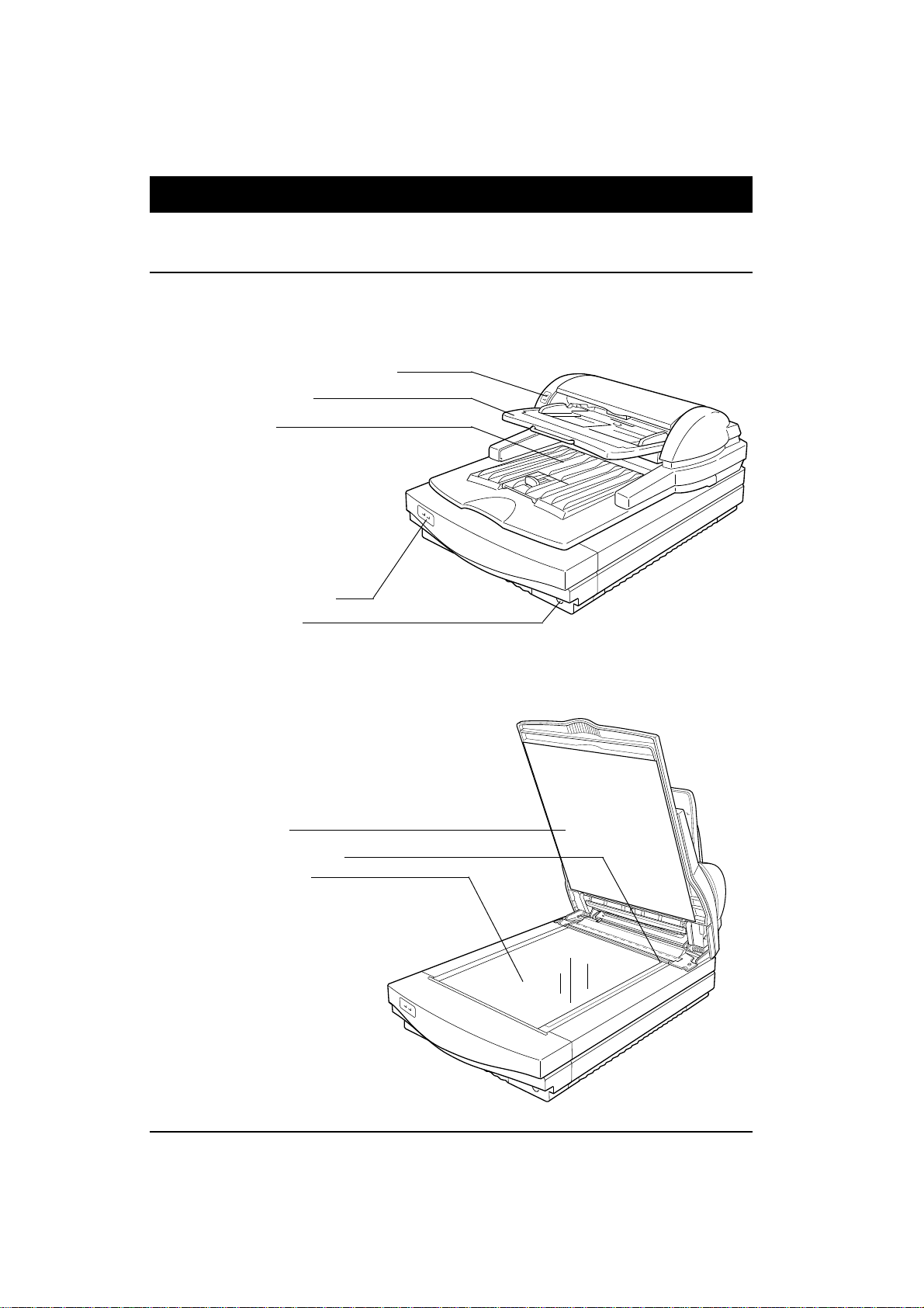
Image Scanner User's Manual
1. Part names
¡ Front view
Closing the document feeder
Document feeder indicators
Document table
Exit table
Scanner indicators
Power switch
Opening the document feeder
White sheet
Document set origin
Contact glass
- 2 -
03_IS430-BODY 97.5.8, 5:35 PMPage 2 PageMaker 5.0J
Page 11
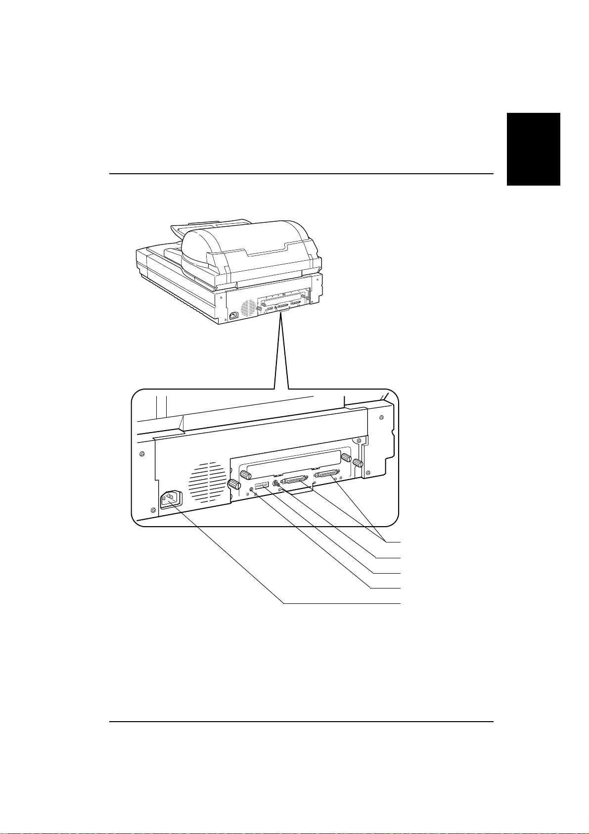
¡ Rear view
Image Scanner User's Manual
Part names
SCSI connectors
Rotary switch
DIP switches
Reset switch
Power cord socket
- 3 -
03_IS430-BODY 97.5.8, 5:35 PMPage 3 PageMaker 5.0J
Page 12
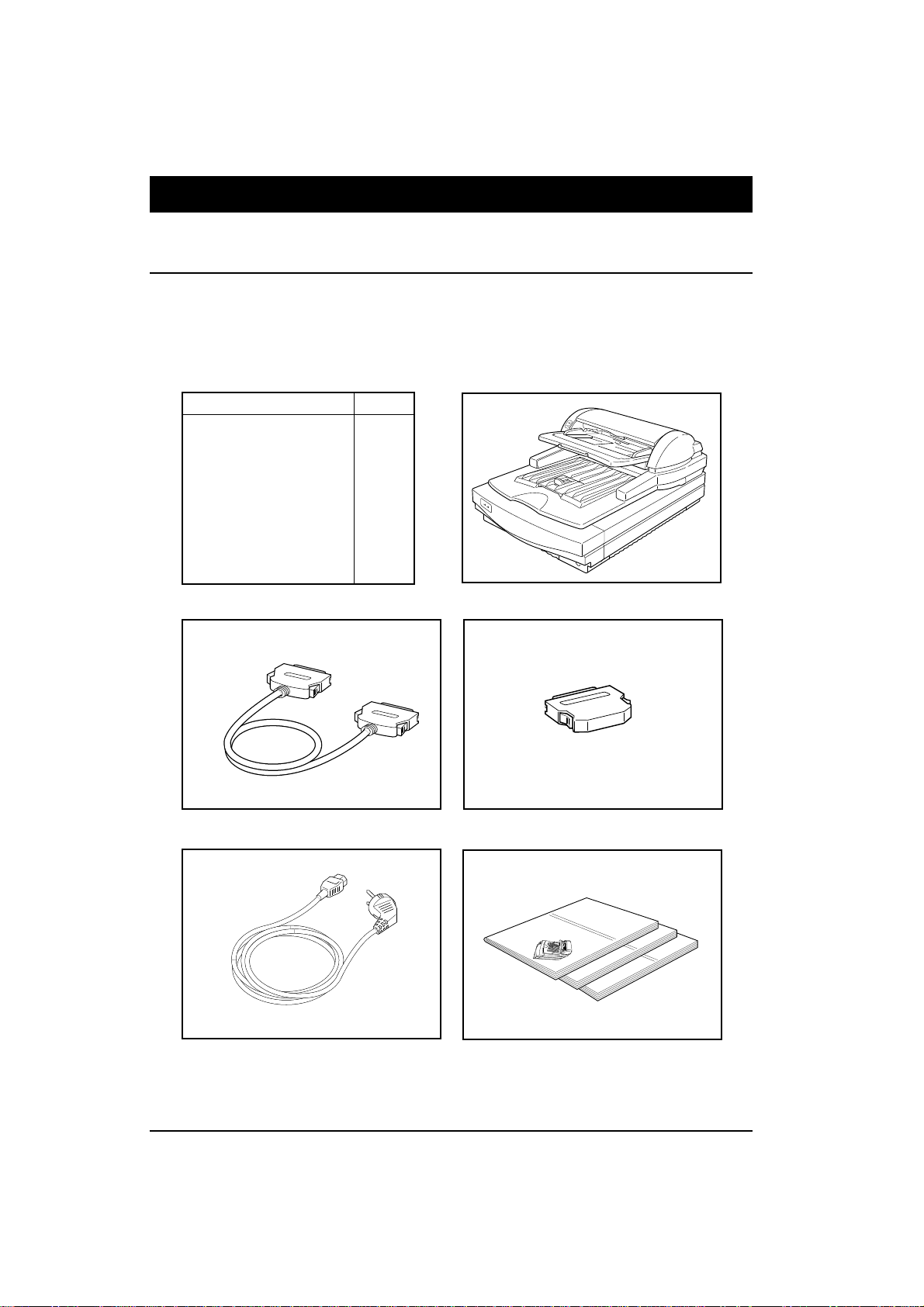
Image Scanner User's Manual
2. Installation
¡ Checking the parts
Make sure that you have all the parts shown below in your packing box.
Parts list
Name Q'ty
Scanner 1
Power cord 1
Terminator 1
SCSI cable 1
User's manual (English) 1
User's manual (German) 1
User's manual (French) 1
Registration card 1
Scanner
SCSI cable
The figure of the power cord varies per country.
Power cord
(Registration card is attached in the same package.)
Terminator
User's manuals
- 4 -
03_IS430-BODY 97.5.8, 5:35 PMPage 4 PageMaker 5.0J
Page 13
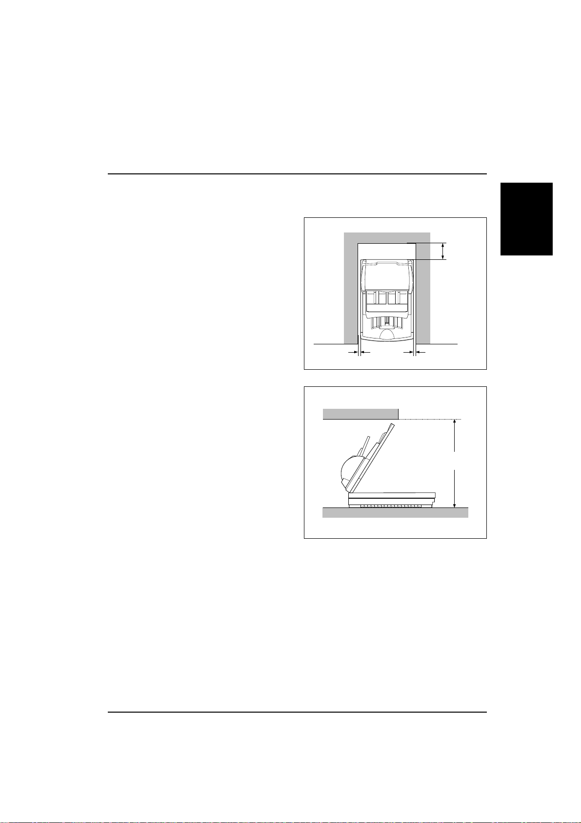
Image Scanner User's Manual
¡ Location
Place the scanner in a location meeting the following environmental requirements.
Operating environment
E Temperature: 10‘ 32˚C
E Humidity: 20‘ 80 RH
E Space
Right: more than 20 mm
Left: more than 20 mm
Behind: more than 130 mm
Front: for operation
Height: more than 720 mm
E Flat base
E Out of direct sunlight
E No vibration
E No dust
more than 20mm
more than 20mm
more than
130mm
Installation
more than 720mm
- 5 -
03_IS430-BODY 97.5.8, 5:35 PMPage 5 PageMaker 5.0J
Page 14

Image Scanner User's Manual
¡ Connecting the SCSI cable
Caution:
E
Connect the cable before turning the power on.
E
The use of interface cables other than shielded cables or specified equivalents will invalidate the certification of this scanner and may cause interference levels which exceed the
limits established for this equipment.
E
The total length of the SCSI bus should be no more than 6 m.
E
Either one of the two SCSI connectors can be used, but an unused SCSI connector must
be capped with a terminator.
This scanner connects to your host computer
through the SCSI (Small ComputerSystem Interface). Connect the cable as follows.
1. Make sure that the power of all devices on
the SCSI chain are turned off.
2. Connect a high-density 50-pin type SCSI
2 cable which complies with ANSI *1 to
the SCSI connector on the rear of the scanner.
3. If the other connecter is not used, cap it with
the attached terminator *2.
*1 Note about SCSI cables
There are several types of SCSI connectors, such as the high density 50-pin connector, the D-sub
25-pin connector, and the 50-pin flat connector. You have to use a SCSI cable that matches the
connectors on your adjacent devices or host computer. This scanner has two high density 50-pin
connectors. The SCSI cable packed with your scanner has a high density 50-pin connector at each
end. If your computer (or any other connected device) has such connectors, you can use the attached cable. However, if you want to connect this scanner with a computer or device that has a
different type of connector, you have to get a cable or a connector adjuster that fits the device or
computer, as well as the scanner. In that case, you must use a SCSI cable that complies with ANSI.
*2 Note about terminators
Generally, you need two terminators at each end of a SCSI chain. If you connect this scanner at the
end of a SCSI chain, you have to cap the scanner's unused SCSI connector with the attached
terminator. If you connect this scanner in the middle of a SCSI chain that is already terminated, you
do not need the attached terminator.
- 6 -
03_IS430-BODY 97.5.8, 5:35 PMPage 6 PageMaker 5.0J
Page 15
¡ Setting the SCSI ID
Image Scanner User's Manual
Caution:
E
No two devices on the SCSI-chain can have the same ID number.
E
The setting will not take effect until the machine is reset.
E
Do not set the SCSI ID to 8 or 9. The SCSI ID must be set between 0 and 7, even though 8
and 9 are present on the rotary switch.
E
If more than two of this manufacturer’s scanners are connected to your system, you can not
use SCAM. In this case, set the unique IDs for each scanners manually.
This scanner supports the SCAM standard. If
your system also complies with this standard,
set DIP switch 3 to OFF position (original
position). The SCSI ID will be assigned
automatically when power is next turned on. If
your system does not comply with this standard,
follow the steps below to set the ID manually.
1. Set DIP switch 3 to the ON positon.
2. Turn the rotary switch and set the number to
the desired SCSI ID number.
3. If you change the SCSI ID while the scanner is on, reset the scanner by turning the
power off and on, or pushing the reset
switch.
12345678
Installation
ON
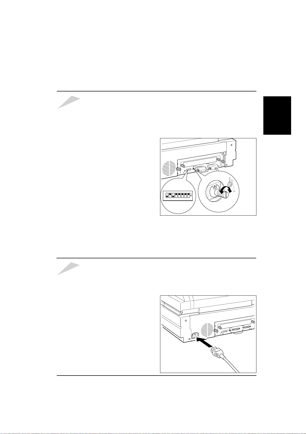
¡ Connecting the power cord
Caution:
1. Make sure that the power switch is turned
off.
2. First, insert the power cable into the power
cord socket at the rear of the scanner.
3. Insert the other side of the power cord into
the plug receptacle.
E
Use the standard cable supplied with this unit. Otherwise, use cables that meet the requirements on page iv.
E
Connect the power cable before turning the power switch on.
E
This product is equipped with a 3-wire grounded power system.
The plug has a grounding pin and must be inserted into a grounded outlet.
- 7 -
03_IS430-BODY 97.5.8, 5:35 PMPage 7 PageMaker 5.0J
Page 16
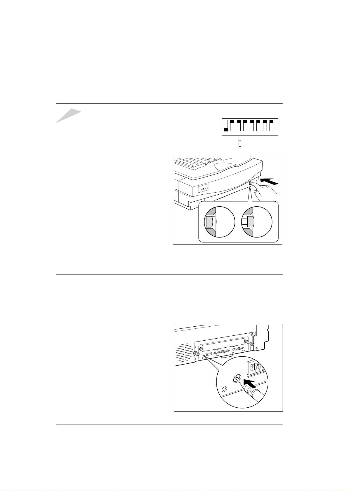
Image Scanner User's Manual
¡ Turning the power on
Caution:
Confirm that the DIP switches on the rear of the scanner
are in the original position as shown right. If the settings
have been changed, correct the settings, otherwise the
scanner may not work correctly. Note : Switch 3 may be in
the ON position if you are not using SCAM — if this is the
case, the setting is correct.
1. Push the power switch at the front of the
scanner.
2. Confirm that the switch is set as shown in
the illustration.
If you want to turn the power off, push the
power switch again.
¡ Initializing the scanner
Original position
12345678
OFF : with SCAM
ON : without SCAM
Power
On
Power
Off
«
ON
Generally, you do not have to initialize the scanner. However, when you change the SCSI ID or
DIP switch settings while the scanner is on, you do need to initialize the scanner.
You can initialize the scanner not only by turning the power off and on but also by pushing the
reset switch at the rear of the scanner.
1. Push the reset switch using a tapered tool
such as the tip of a mechanical pencil.
2. Confirm that the four indiators light for a
few seconds. This means the scanner is
intializing.
- 8 -
03_IS430-BODY 97.5.8, 5:35 PMPage 8 PageMaker 5.0J
Page 17
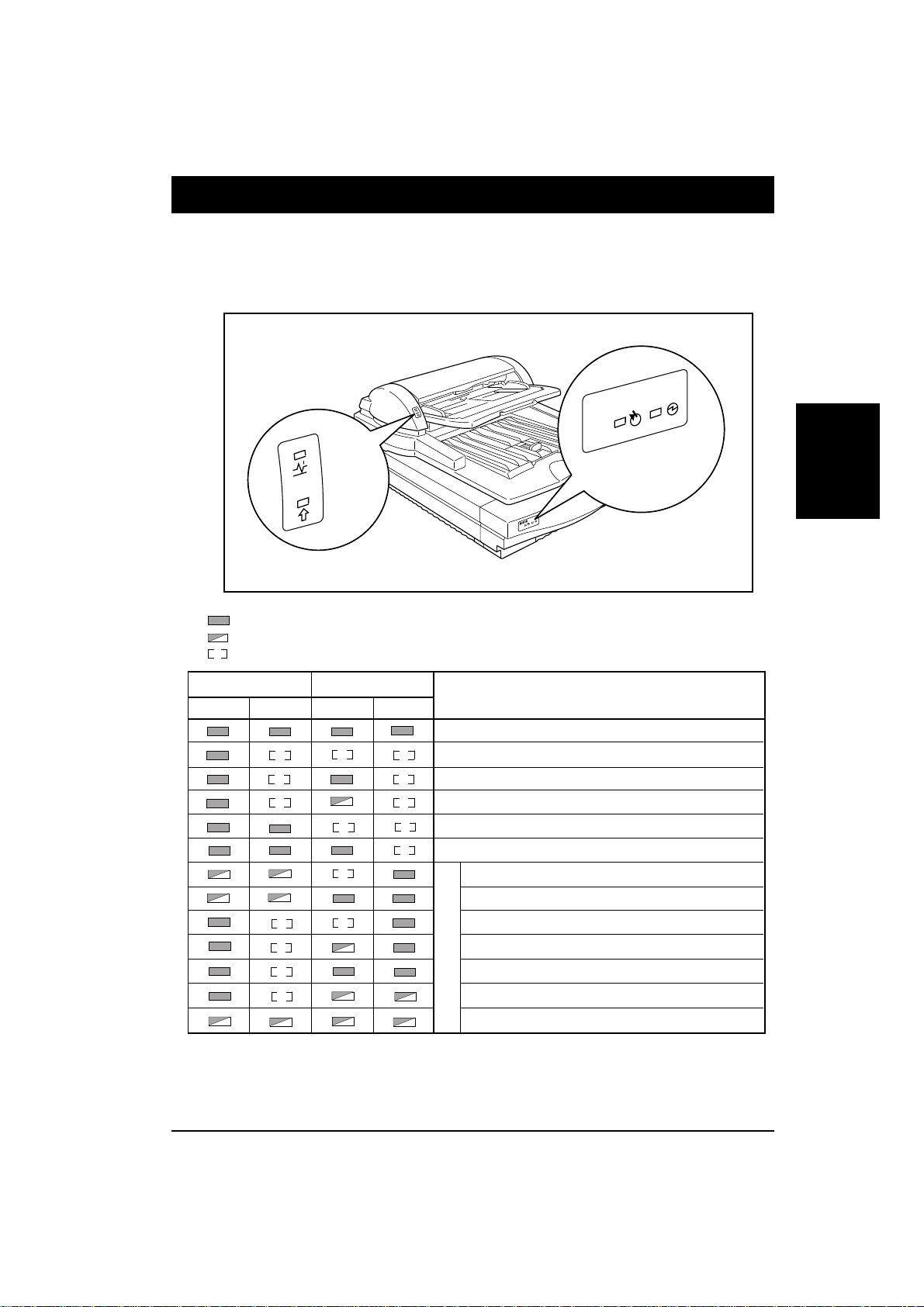
Image Scanner User's Manual
3. Indicators . Setting the document
The condition of the scanner is indicated by a combination of the lit indicators on the scanner and
the document feeder.
Installation
(amber)
(green)
: On
: Blinking
: Off
Scanner Document feeder
Green Amber Green Amber
(green)
(amber)
Meaning
Initializing/Checking
Ready (No document is on the document feeder)
Ready (Document is on the document feeder)
Ready (Document feeder requires a document)
Busy (No document is on the document feeder)
Busy (Document is on the document feeder)
Lamp cover open
Lamp error
Document feeder cover open
Paper jam
Error
Paper misfeed
Document table error
System error
Indicators
If any of the above errors occur, see troubleshooting on page 16.
- 9 -
03_IS430-BODY 97.5.8, 5:36 PMPage 9 PageMaker 5.0J
Page 18
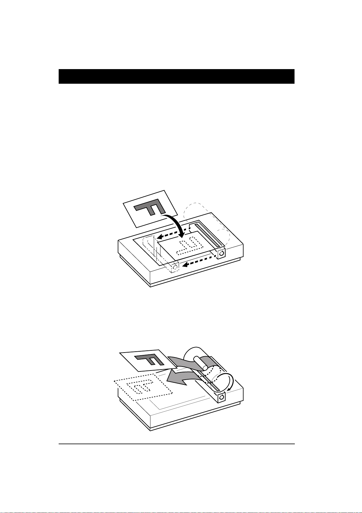
Image Scanner User's Manual
4. Placing originals
You can scan your originals two ways. You can place them one at a time directly on the contact
glass (book mode) or you can place all of them on the document feeder (document feeder mode).
Placing originals on the contact glass is the only way to scan books, magazines and the like. You
can also scan single sheets this way.
Using the document feeder is ideal when you have many sheets to scan. Place your originals on the
document table and they will be fed in and scanned automatically.
Book mode
Document feeder mode
- 10 -
03_IS430-BODY 97.5.8, 5:36 PMPage 10 PageMaker 5.0J
Page 19
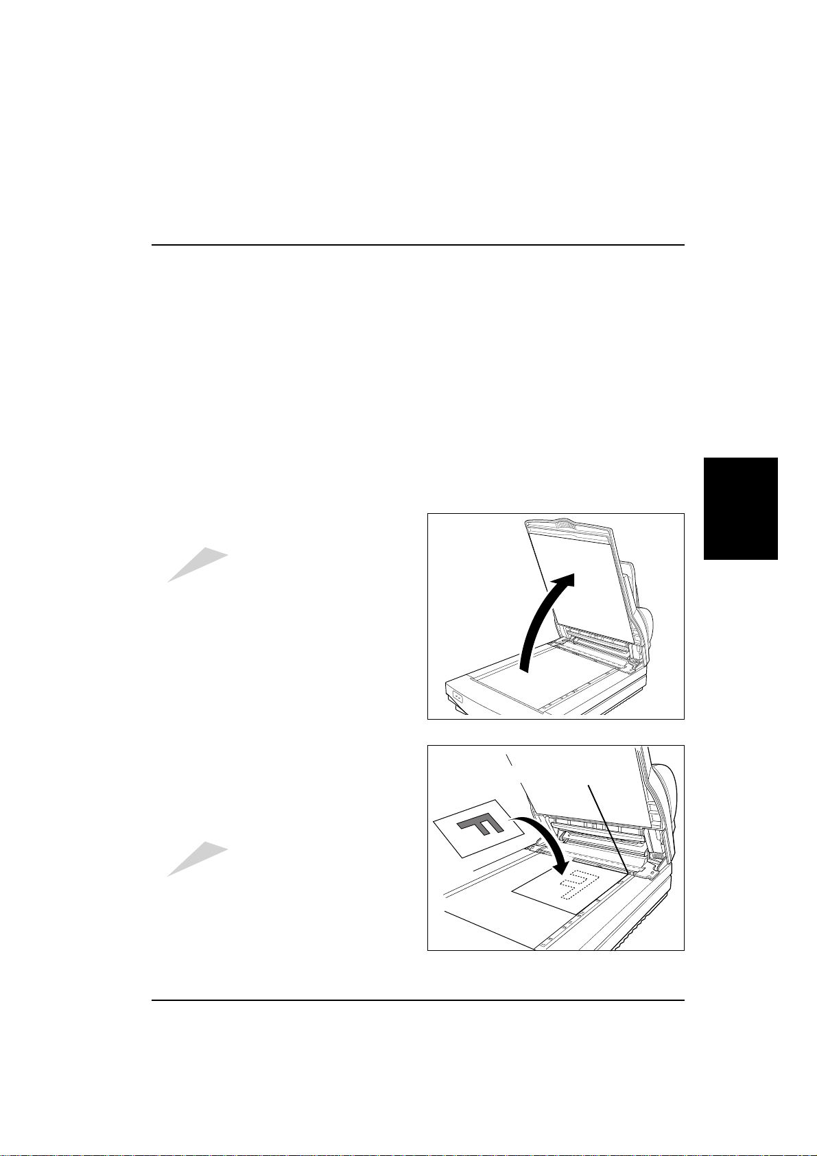
Image Scanner User's Manual
¡ Placing an original on the contact glass
Original condition
Originals that meet the following specifications can be scanned.
E Weight: Less than 10 kg per document (Letter or A4)
E Thickness: Less than 10 mm
E Written material: Pencil, toner, ink, ball point pen, anything that does not stick to the contact
glass.
Procedures
(If document feeder is open, more than 10 mm is possible.)
1. Open the document feeder.
Caution:
Don't press on the contact glass
strongly, otherwise it might break.
2. Put the original face down on the contact
glass. Place the upper left edge of the original at the document set origin.
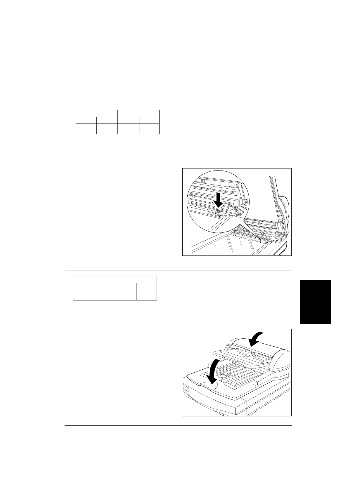
3. Close the document feeder slowly.
Caution:
Keep your fingers away from the
hinge when closing the document
feeder.
Document set origin
Placing
originals
- 11 -
03_IS430-BODY 97.5.8, 5:36 PMPage 11 PageMaker 5.0J
Page 20

Image Scanner User's Manual
¡ Placing originals on the document table
Original condition
Originals that meet the following specifications can be handled by the document feeder.
Caution:
E Size: Length: 120 ‘ 432 mm
E Weight: 11.2 lb ‘ 34.1 lb (42 g/m2 ‘ 128 g/m2)
E Stack: All originals must be the same width
E Paper: Bond paper, PPC paper, or art/coating paper
E Thickness: 0.07 ‘ 0.16 mm
E Written material: Toner, pencil, marker ink, water sign pen, ball point pen or ink that does not
E Curl: Back curl: Less than 5 mm Face curl: Less than 10 mm
E Others: No tears, wrinkles, perforations, and pastes.
When an original needs to be scanned that does not meet the following specifications,
place the original on the contact glass and scan in book mode, otherwise your original may
be damaged.
Width: 69 ‘ 297 mm
Height is less than 12 mm
(Ex: 20lb paper~ 100, 24lb paper~ 85)
adhere to the contact glass and the roller. Ink must be dry.
If curled, flatten it within the above levels.
No projections such as a clip or staple.
No folds within the following area.
Folds should not be on this area
because the optical sensor
watches this area of an original.
1 mm
- 12 -
03_IS430-BODY 97.5.8, 5:36 PMPage 12 PageMaker 5.0J
c
10 mmcenter
feeding direction
Page 21
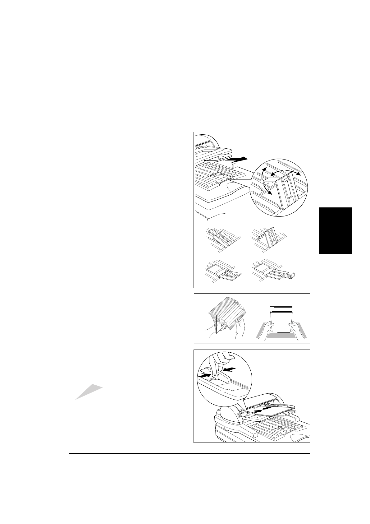
Procedures
1. When scanning large size originals, extend
the document table.
Note: If the extention of the document table is
pushed down strongly, it will come off to
prevent it from damaging. If it comes off,
put it back .
2. Adjust the exit table stopper according to
the size of the original.
Image Scanner User's Manual
Placing
originals
3. Fan and then square the stack of originals.
4. While holding the guide stopper on the left
guide, adjust the document guides to the
width of originals.
Caution:
Adjust the guide before setting originals, otherwise the inner mylar might
be damaged.
5. Place the originals face up into the document table until the green indicator of the
document feeder lights.
- 13 -
03_IS430-BODY 97.5.8, 5:36 PMPage 13 PageMaker 5.0J
Page 22
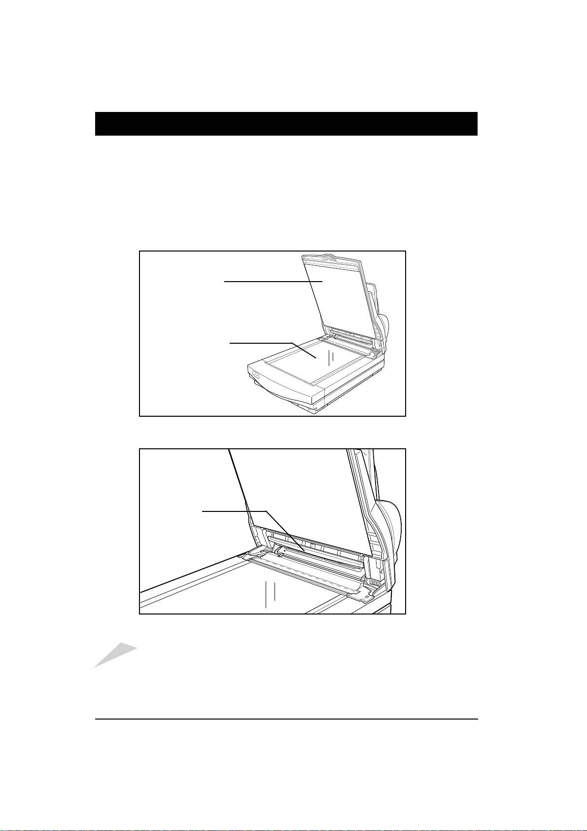
Image Scanner User's Manual
5.Cleaning
If the contact glass or the white sheet is dirty, it will adversely affect the quality of the scanned
image. If the roller of the document feeder is dirty, it can cause paper jams, misfeeds, or soil the
originals. The above mentioned parts must always be kept clean.
Before scanning, clean the contact glass, the white sheet, and the platen by wiping them with a dry
soft cloth.
White sheet
Contact glass
Platen
Caution:
Don't press on the contact glass strongly, otherwise it might break.
Keep your fingers away from the hinge when closing the document feeder.
- 14 -
03_IS430-BODY 97.5.8, 5:36 PMPage 14 PageMaker 5.0J
Page 23
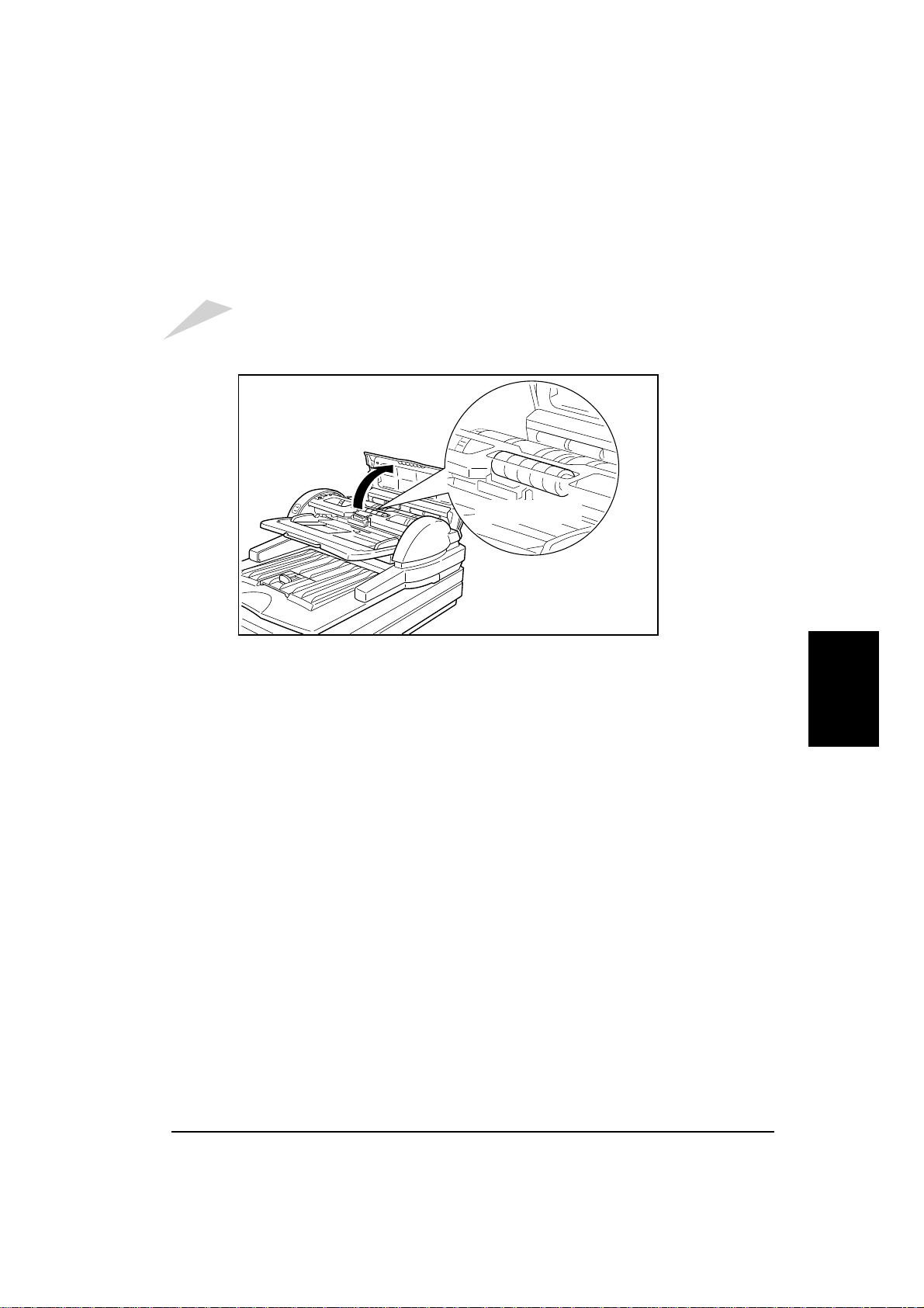
Image Scanner User's Manual
If feed errors such as jams and/or double feeds occur, open the document feeder cover and clean
the feed roller by wiping it with a damp cloth.
Caution:
Clean the roller after scanning an original written with material that doesn't stick well to the
sheet, such as pencil lead. Otherwise the next original may be soiled.
Feed roller
Cleaning
- 15 -
03_IS430-BODY 97.5.8, 5:36 PMPage 15 PageMaker 5.0J
Page 24
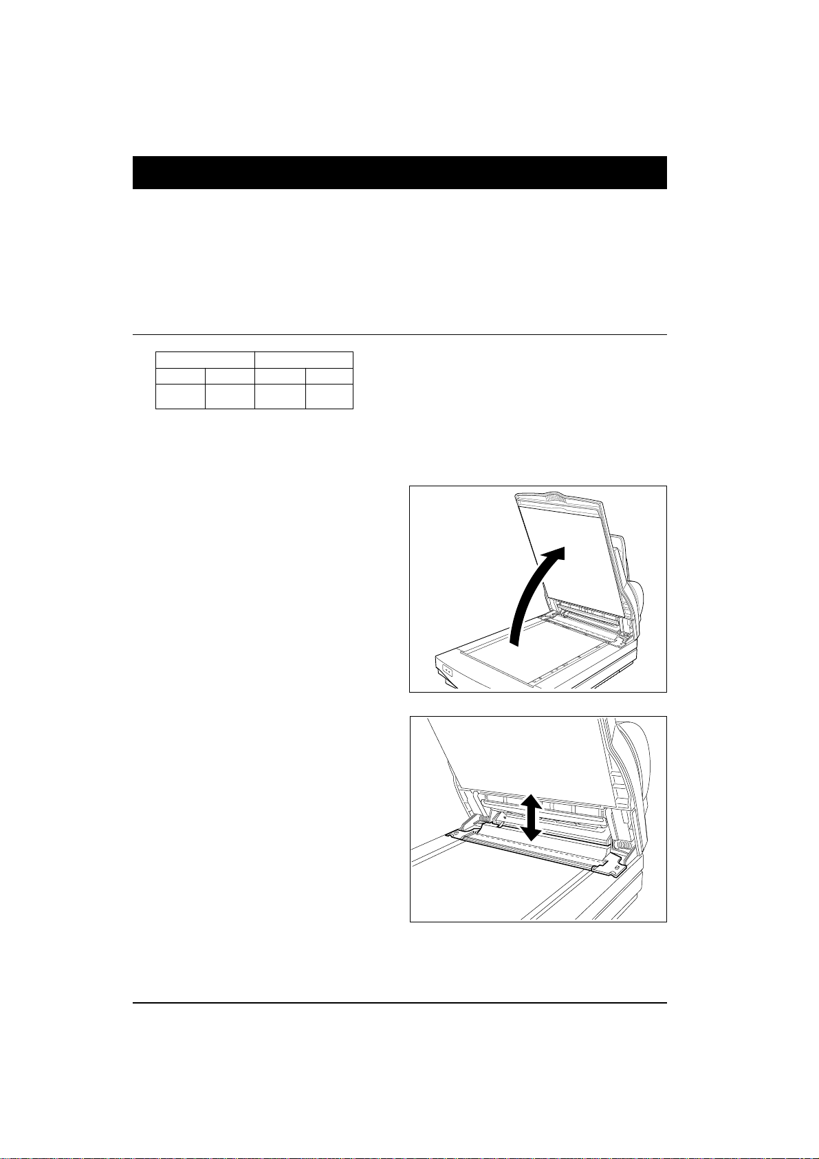
Image Scanner User's Manual
6. Troubleshooting
If an error occurs, the type of error is indicated by a combination of lit indicators, as mentioned on
page 9. Follow the appropriate directions below. If the error is not solved by the measures given
below, contact your service representative for assistance.
¡ Lamp cover open
Scanner Document feeder
Green Amber Green Amber
Blinking Blinking Off On
This indicates that the lamp cover is not closed.
Corrective action
1. Open the document feeder.
2. Remove the lamp cover and then reinstall it correctly.
- 16 -
03_IS430-BODY 97.5.8, 5:36 PMPage 16 PageMaker 5.0J
Page 25
¡ Lamp error
Scanner Document feeder
Green Amber Green Amber
Blinking Blinking On On
This indicates that the CCD does not sense light from the lamp.
The lamp may be burned out or the connector may be disconnected.
Corrective action
Remove the lamp connector and then reinstall it correctly refering to page 36.
If the error is not solved, the lamp may be
burned out. Call your service representative to
buy a new lamp. Refer to page 36 to replace it.
Image Scanner User's Manual
¡ Document feeder cover open
Scanner Document feeder
Green Amber Green Amber
On Off Off On
This indicates that the document feeder cover, and/or the document feeder is not closed.
Corrective action
Close the document feeder and/or the document feeder cover.
Trouble-
shooting
- 17 -
03_IS430-BODY 97.5.8, 5:36 PMPage 17 PageMaker 5.0J
Page 26
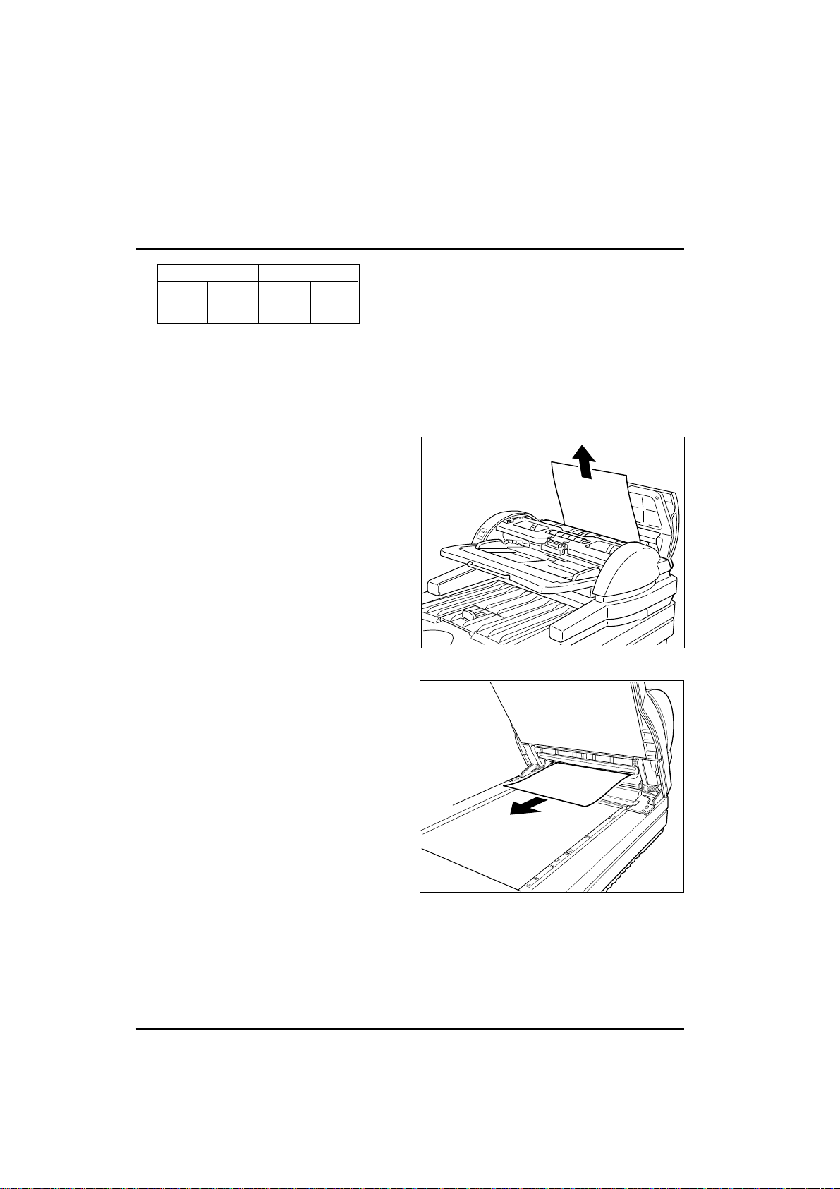
Image Scanner User's Manual
¡ Paper jam
Scanner Document feeder
Green Amber Green Amber
On Off Blinking On
This indicates that an original is jammed in the document feeder.
Corrective action
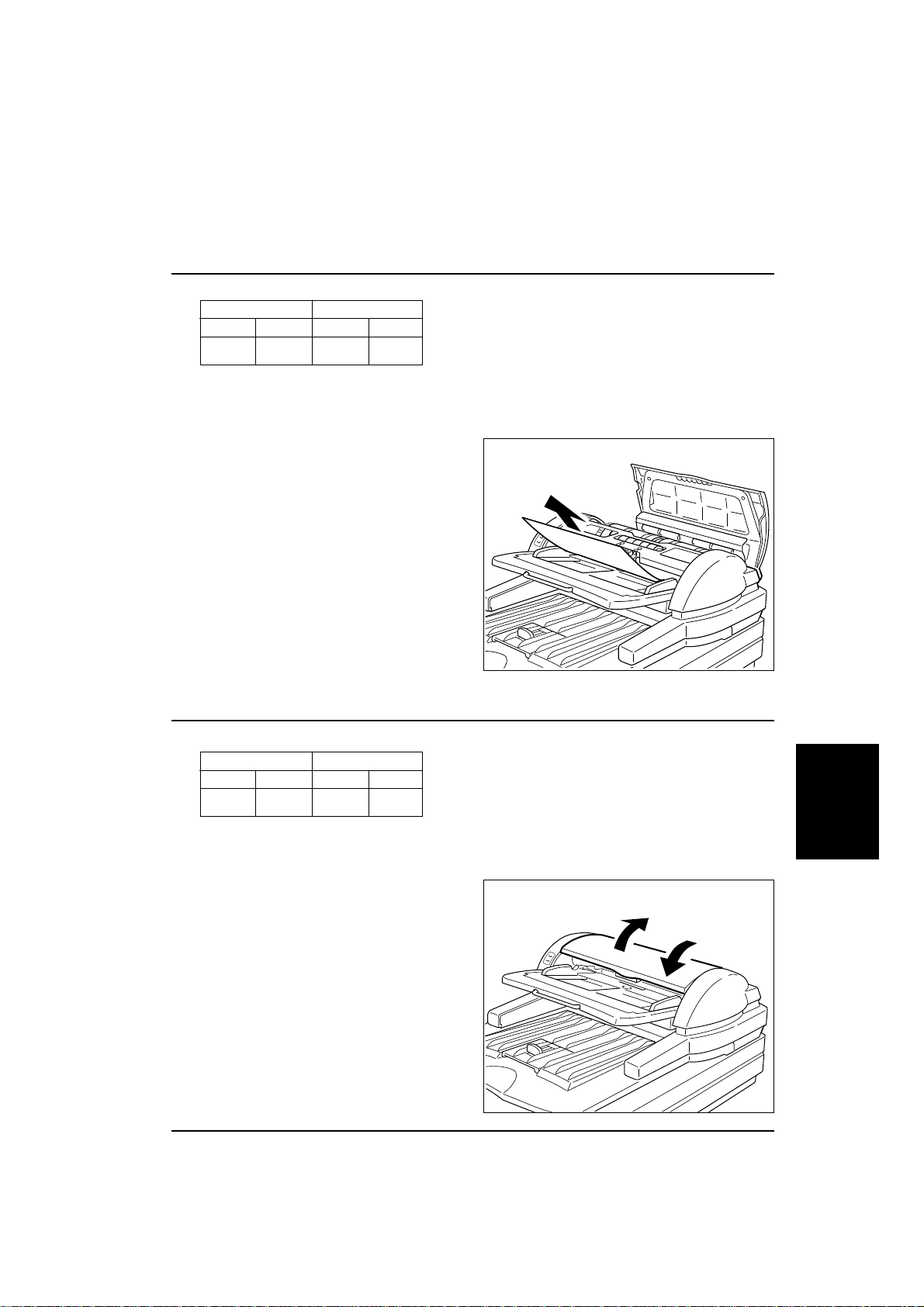
1. Open the document feeder cover.
If you can't see the document, see steps
4 to 6.
2. Pull out the jammed paper.
3. Place the original again refering to
"Original condition" and "Procedure"
on page 12 and 13.
4. Open the document feeder.
If you can't see the document, contact
your service representative.
5. Pull out the original gently.
6. Place the original again refering to
"Original condition" and "Procedure"
on page 12 and 13.
- 18 -
03_IS430-BODY 97.5.8, 5:36 PMPage 18 PageMaker 5.0J
Page 27
¡ Paper misfeed
Scanner Document feeder
Green Amber Green Amber
On Off On On
This indicates that the document feeder fails to feed the originals.
Corrective action
1. Open the document feeder cover.
2. Pull out the original.
3. Place the original again refering to
"Original condition" and "Procedure" on
page 12 and 13.
Image Scanner User's Manual
¡ Document table error
Scanner Document feeder
Green Amber Green Amber
On Off Blinking Blinking
This indicates that the document table is not in the correct posititon.
Corrective action
Open the document feeder cover and then
close it.
Trouble-
shooting
- 19 -
03_IS430-BODY 97.5.8, 5:36 PMPage 19 PageMaker 5.0J
Page 28

Image Scanner User's Manual
¡ System error
Scanner Document feeder
Green Amber Green Amber
Blinking Blinking Blinking Blinking
Corrective action
Initialize the scanner by switching the scanner off and on again or press the reset switch.
If the error is not solved, please contact your service representative.
¡ Others
If a problem occurs that is not indicated by the indicators, follow the directions below.
Problem
Power does not
go on.
Does not run after power is on.
Originals are not
fed normally.
Scanned image
is abnormal.
Cause
Power cord is not plugged in.
Power switch is not turned on.
I/F cable is not connected securely.
Host computer malfunction.
SCSI ID is not correct.
DIP switches setting is not correct.
The roller is not clean.
Specifications of originals do not
match with the document conditions.
The contact glass is not clean.
The roller is not clean.
Corrective action
Plug the power cord in.
Turn on the power.
Connect it securely.
Reset the computer.
Correct the SCSI ID.
Correct the DIP switches
setting.
Clean the roller.
Place originals which
match the document conditions.
Clean the contact glass.
Clean the roller.
Refer
P.7
P.8
P.6
P.7
P.8
P.15
P.12
P.14
P.15
- 20 -
03_IS430-BODY 97.5.8, 5:36 PMPage 20 PageMaker 5.0J
Page 29

7. Specifications
Image Scanner User's Manual
Type :
Scanning method : Flat bed & Sheet feed
Scanning area : Main direction 304 mm max.
Desktop type
Sub direction 432 mm max.
Resolution : Main direction 400 dpi
Sub direction 400 dpi
Grayscale : 4, 6 or 8 bits / pixel
Speed : Max. 50 ppm (page per minute) A4/Letter portrait by 200 dpi, binary with
the document feeder
* Scanning speed depends on the system environment.
Interface: SCSI 2
Video interface with the optional video interface unit
Power: AC 120V (60Hz), 220 ‘ 240 V (50 Hz)
Power consumption : Standby: 65 W max. (without optional units)
Processing: 83 W max. (without optional units)
Dimension : 450 mm (W) ~ 670 mm(D) ~ 282 mm (H)
17.7 " (W) ~ 26.4 " (D) ~ 11.1 " (H)
Weight : Approximately 25 kg
- 21 -
03_IS430-BODY 97.5.8, 5:36 PMPage 21 PageMaker 5.0J
Specifications
Page 30

Image Scanner User's Manual
Appendix
Functions
Note: The scanner is controlled by software. Some software does not support all of this
scanner's functions. Unsupported functions are not available.
The names given to functions in this manual may be different from the names used by
the software. Please refer to your software manual for details.
The following functions are described.
Prescan
Scan
Scanning composition
Binary scanning/Threshold
Halftone scanning
Multi-value scanning
Area extraction
Section area (Multi area settings)
Auto photo/letter
Resolution
Brightness
Contrast
Gamma correction
Binary filter
Parameter download
Document size detection
Skew detection
Semi-automatic document feed (SADF) mode
- 22 -
03_IS430-BODY 97.5.8, 5:36 PMPage 22 PageMaker 5.0J
Page 31

¡ Prescan
Image Scanner User's Manual
Function:
Usage:
¡ Scan
Function:
Usage:
Scanning the whole available area at a low resolution (60, 75, or 100DPI*).
Use "Prescan" when you want to obtain a qu ick, low-r esolution scanned ima ge. You
can then adjust the scan area so that subsequ ent scan s apply to exactly the part of the
original you want to scan.
*DPI stands for dots per inch and is a measu re of resolution. Sometimes PPI (pixel
per inch) is used instead of DPI. The higher the resolution, the finer the detail.
Scanning a selected area with all desired settings.
Enter settings such as the scan are a, scannin g composit ion, resolut ion, and so on,
and then scan using "Scan".
Determine the value of the settings based on the original and the output device
(screen, printer, etc.). Even if you scan an image at high resolution, you cannot
output it at high resolution with a low-resolution output device. Scanning an image
at high resolution requires much more memory space and processing time.
- 23 -
03_IS430-BODY 97.5.8, 5:36 PMPage 23 PageMaker 5.0J
Appendix
Page 32
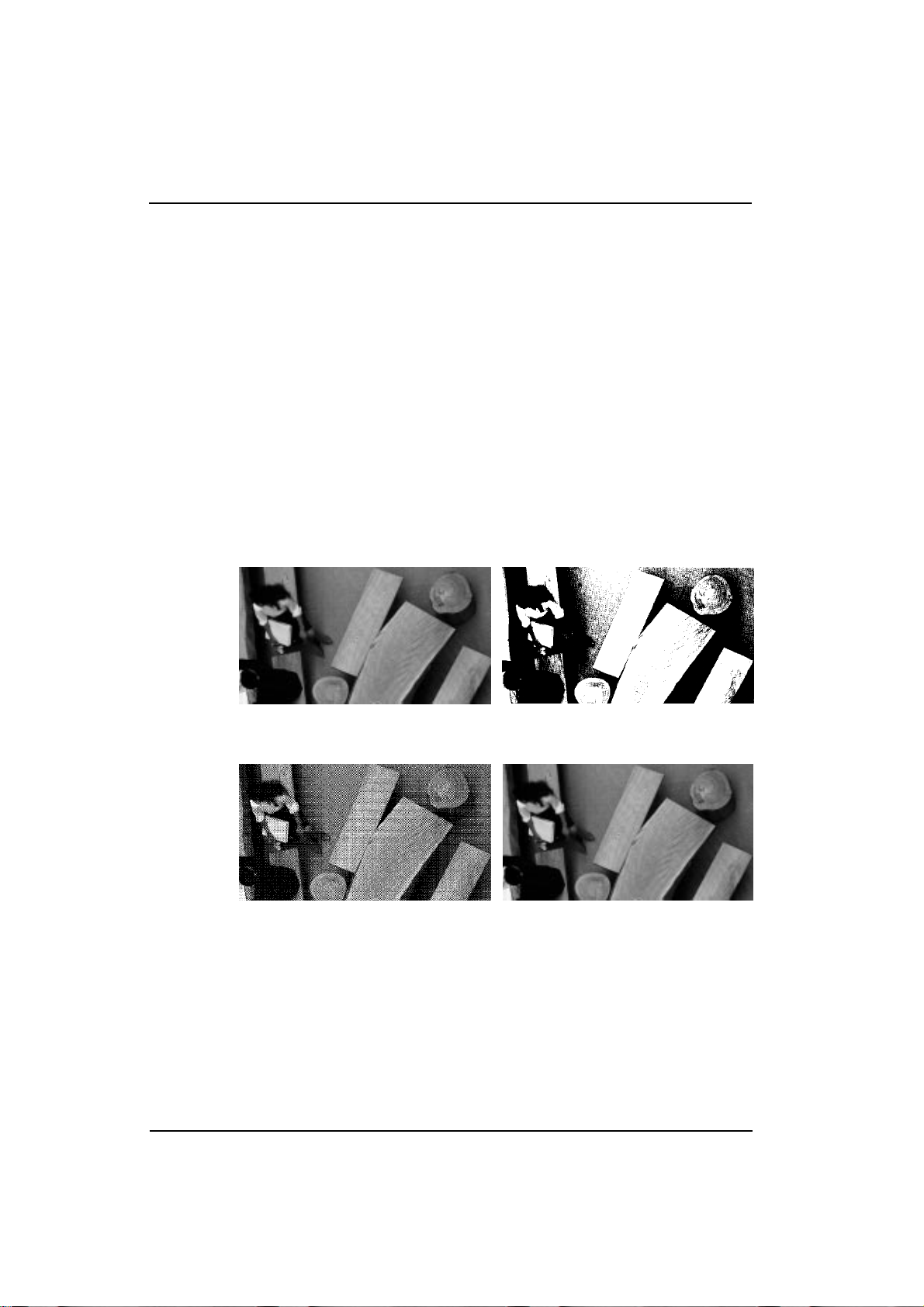
Image Scanner User's Manual
¡ Scanning composition
Function:
Usage:
You can scan using one of three compositions; binary, halftone, or multi-value.
Binary scanning records only black and white from the original. Halftone scanning records gray shades on the original using a pattern of black and white dots to
represent these shades. Multi-value scanning records grays over 16, 64, or 256
levels.
Use binary scanning to scan images with no gray shading, such as text or line art.
Use halftone scanning to scan an image with gray shading such as a photograph, to
be printed or displayed on a monochrome device, such as a laser printer.
Use multi-value scanning to scan an image with gray shading, such as a photograph,
to be printed or displayed on a gray scale device.
Refer to the following pages for details.
Original Binary scanned image
Halftone scanned image Multi-value scanned image
- 24 -
03_IS430-BODY 97.5.8, 5:36 PMPage 24 PageMaker 5.0J
Page 33
¡ Binary scanning / Threshold
Image Scanner User's Manual
Function:
Usage:
A binary composition scanning converts eve ry p ixel on the imag e to either black or
white. If the image contains a gr ay area, the threshold value determin es whe ther the
scanner records it as bl ack or white. If the thresh old value is high, the sca nner
records more pixels a s bl ac k. If t he th reshold va lue is low, th e sca nner r ecords few er
pixels as black.
Use a binary composition when scanning binary images such as text and line drawings; black and white images without any gray areas.
You can select one of following two methods to set the threshold value in binary
scanning; manual threshold or dynamic threshold.
Manual threshold
A whole image is binal ized usi ng a speci fied thr eshold. The th reshold c an be set
between 1 and 255 . Whe n scanni ng a l igh t imag e, se t t he thr es hold h ig her. Wh en
scanning a dark image, set the threshold lower.
Lower threshold
Higher threshold
Dynamic threshold
The scanned image is binalized with an appropriate threshold as determined by the
scanner by using an optional image processing unit.
Dynamic threshold
- 25 -
03_IS430-BODY 97.5.8, 5:36 PMPage 25 PageMaker 5.0J
Appendix
Page 34
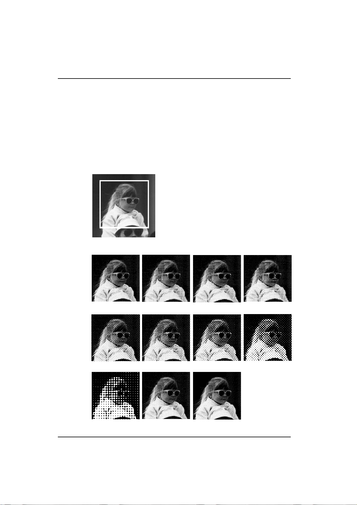
Image Scanner User's Manual
¡ Halftone scanning
Function:
Usage:
Halftone creates the illusion of gray scales by simulating shades of gray from patterns of black and white dots.
Use halftone scanning when scaning an image with gray shadings such as a photograph, to be printed or displayed on a monochrome device, such as a laser printer.
Halftoning saves memory, so it is convenient for filing a large amount of image
data. This scan ner h as elev en hal ftoni ng meth ods: ten d ithe ring me thods and o ne
error diffusion method.
Original
8~4 45
12~6 45
16~16 90 8~8 Bayer Error diffusion
6~6 90 8~6 60 8~8 90
10~8 60
12~8 60
16~8 45
- 26 -
03_IS430-BODY 97.5.8, 5:36 PMPage 26 PageMaker 5.0J
Page 35
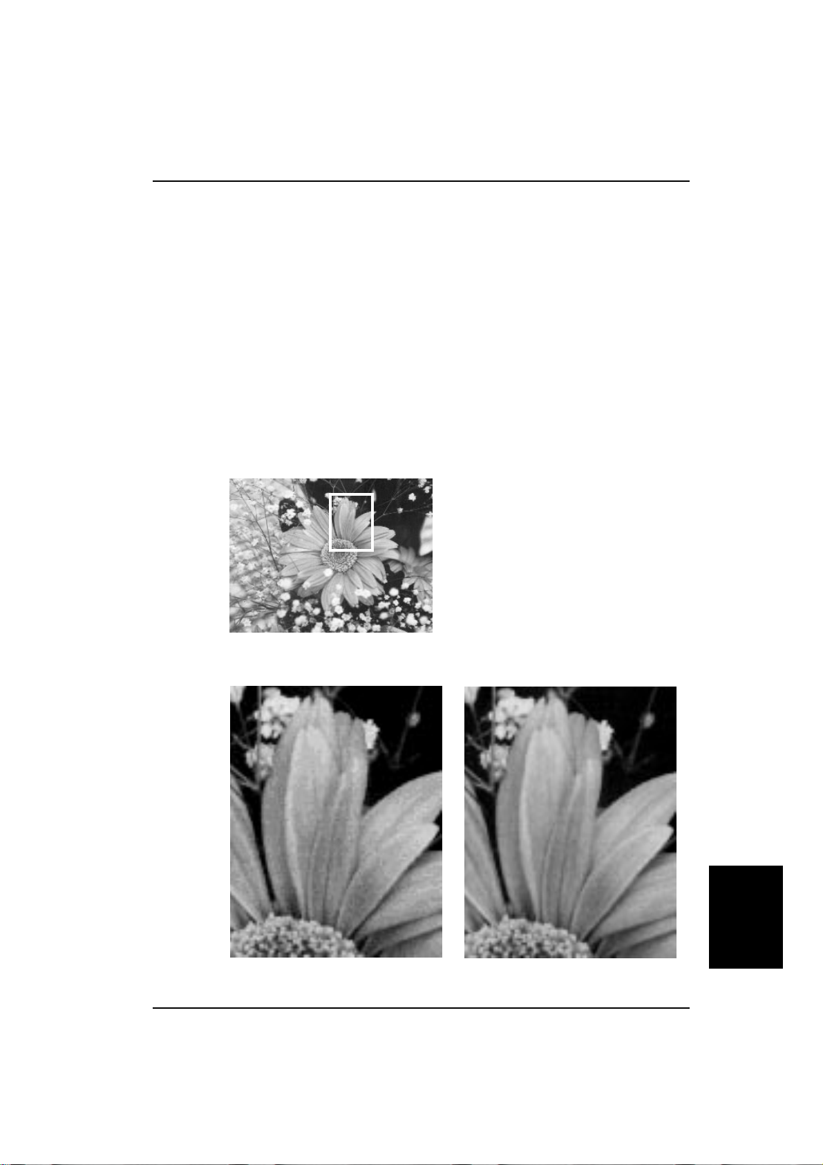
¡ Multi-value scanning
Image Scanner User's Manual
Function:
Usage:
Multi-value sca nning ca n record 4, 6, or 8 bits of informa tion fo r each do t on t he
image.
The 4-bit multi-value data represents 16 different shades of gray, th e 6-bit data r epresents 64 shades of gray, 8-bit data represents 256 different shades of gray.
Note that the multi-v alue scanning uses more mem ory and disk space. For ex amp le,
8-bit scanning needs 8 times spac e more tha n binary (1- bit) scanni ng of the same
scan area.
Uses multi-value scanning to scan an image with gray shading, such as a photograph, to be printed or displayed on a gray scale device.
Select 4-bit, 6-bit, or 8-bit according to the gray level of your output device.
Original
4-bit image
Appendix
8-bit image
- 27 -
03_IS430-BODY 97.5.8, 5:36 PMPage 27 PageMaker 5.0J
Page 36
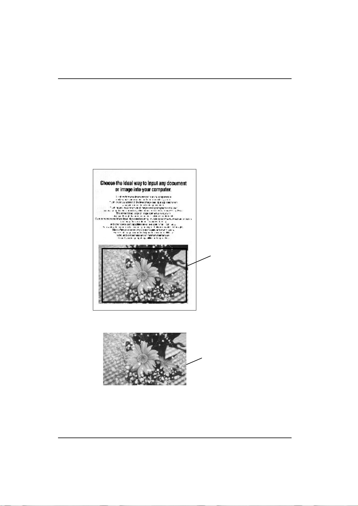
Image Scanner User's Manual
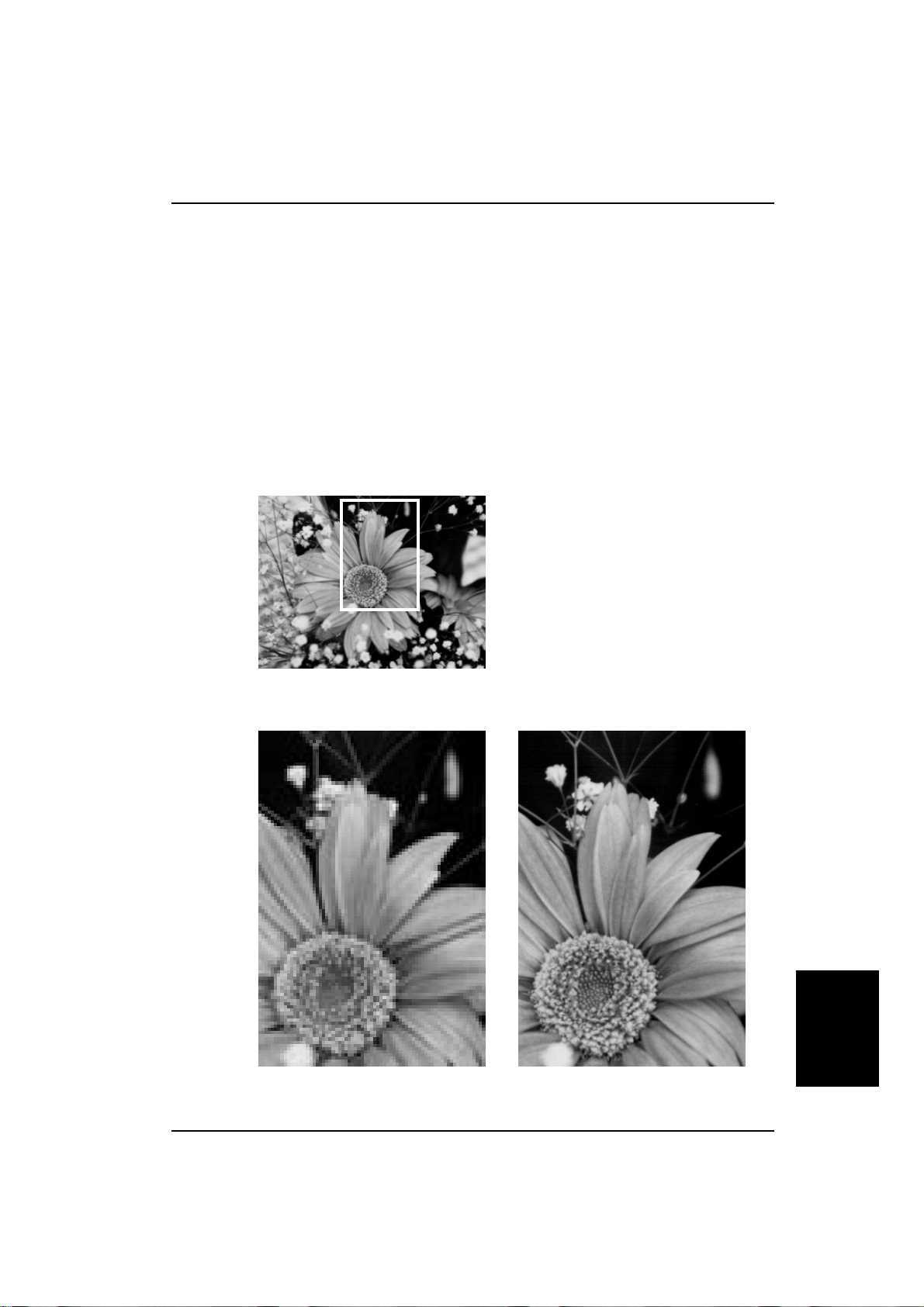
¡ Area extraction
Function:
Usage:
To extract a rectangular area from the whole scannable area.
For example, if you want to extr act a photogra ph from a page, define a rec tangle
over the photograph, as shown below.
The position of the area is decided by setting the X and Y co-ordinates of the leftupper corner of the rectangle. The size is d ecid ed by settin g the ver tical and horizontal lengths, which can be set separately.
Defined area
Original
d
Scanned this area only
Scanned image
- 28 -
03_IS430-BODY 97.5.8, 5:36 PMPage 28 PageMaker 5.0J
Page 37
¡ Section area (Multi area settings)
Image Scanner User's Manual
Function:
Usage:
Within the scannable area, you can set rectangular areas and define scanning modes
such as binary scanning, halftone scanning, or binary filter etc. for each area. Six
areas can be set for one scan. These area s can be p iled on top o f one an other and the
last defined area is valid.
Note:
If six areas are piled, depending on how they are piled, scanning may not result in the
correct mode. Reset the areas, after decreasing the number of areas or their sizes.
When scanning an original which includes binary image s and h a lfto ne imag es, yo u
can scan each image with its own composition method in one scanning.
1. Set binary composition for the whole
scannable area.
2. Set halftone composition for this area.
3. Set halftone composition for this area.
4. Set halftone composition for this area.
Original / Example settings
d
Scanned in example settings
In the case of scanning without this function
Scanned whole
area in binary setting
Scanned whole area
in halftone setting
Appendix
- 29 -
03_IS430-BODY 97.5.8, 5:36 PMPage 29 PageMaker 5.0J
Page 38
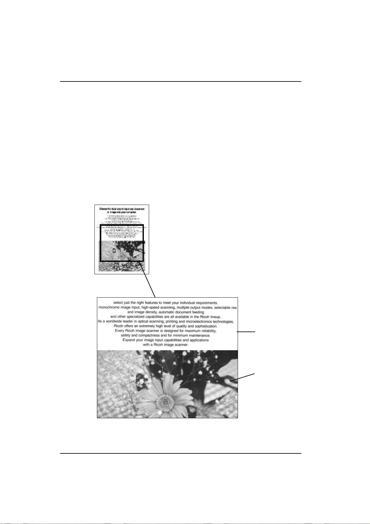
Image Scanner User's Manual
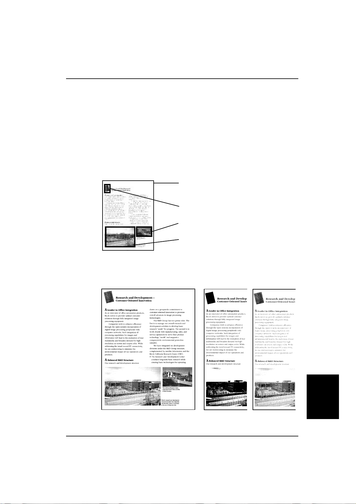
¡ Auto photo/letter
Function:
Usage:
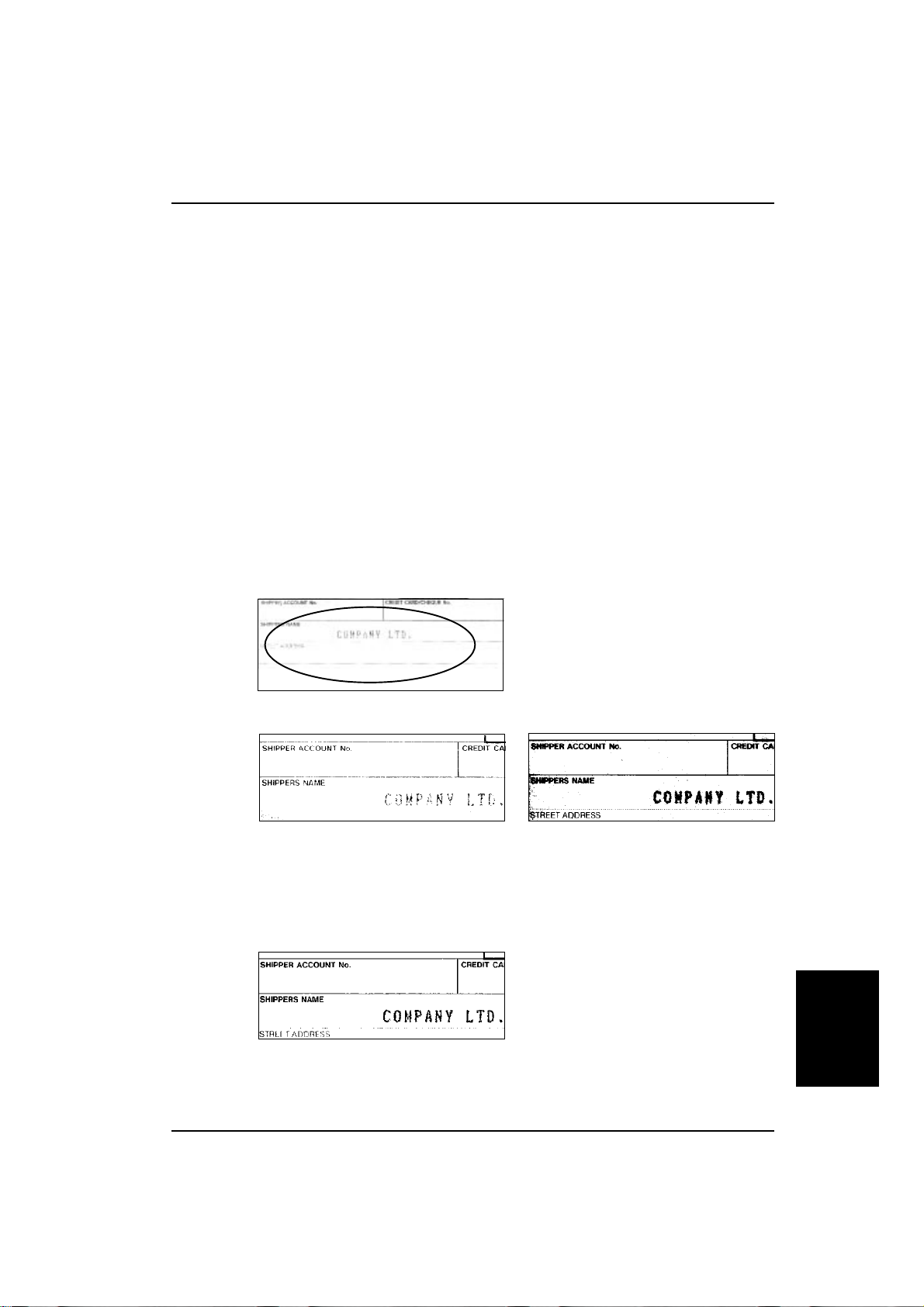
This mode detects photo (halftone) areas and letter (binary) a reas of the origina l so
that the binary areas are scanned in the binary mode, and the halftone areas are
scanned in the halftone mode.
Note:
This function is available only when t he opt ional im age processing unit is inst alled i n
the scanner.
If binary areas and halftone areas are not separated clearly, segmentation may not
be achieved .
Scanning of an original that includes binary images such as letters, and halftone
images such as photographs.
Original
Scanned image
Scanned in binary
composition
Scanned in halftone composition
- 30 -
03_IS430-BODY 97.5.8, 5:37 PMPage 30 PageMaker 5.0J
Page 39
¡ Resolution
Image Scanner User's Manual
Function:
Usage:
To set vertical and horizontal resolution independently at 60, 75, and 100 to 800
dots per inch.
The higher the resolution, the finer the detail. However, a high resolution image
requires much more memory space and processing time than a low resolution image.
Note: If the resolution is set at more than 400 dpi, the maximum scanning width is less than
304 mm.
Generally, setting the scanning resolution at the resolution of your output device
results in high quality imaging. A lower resolution means lower quality and a higher
resolution is a waste of memory. However, if you change the scale of your image,
modify the resolution according to the scale.
Original
Lower
Higher
- 31 -
03_IS430-BODY 97.5.8, 5:37 PMPage 31 PageMaker 5.0J
Appendix
Page 40
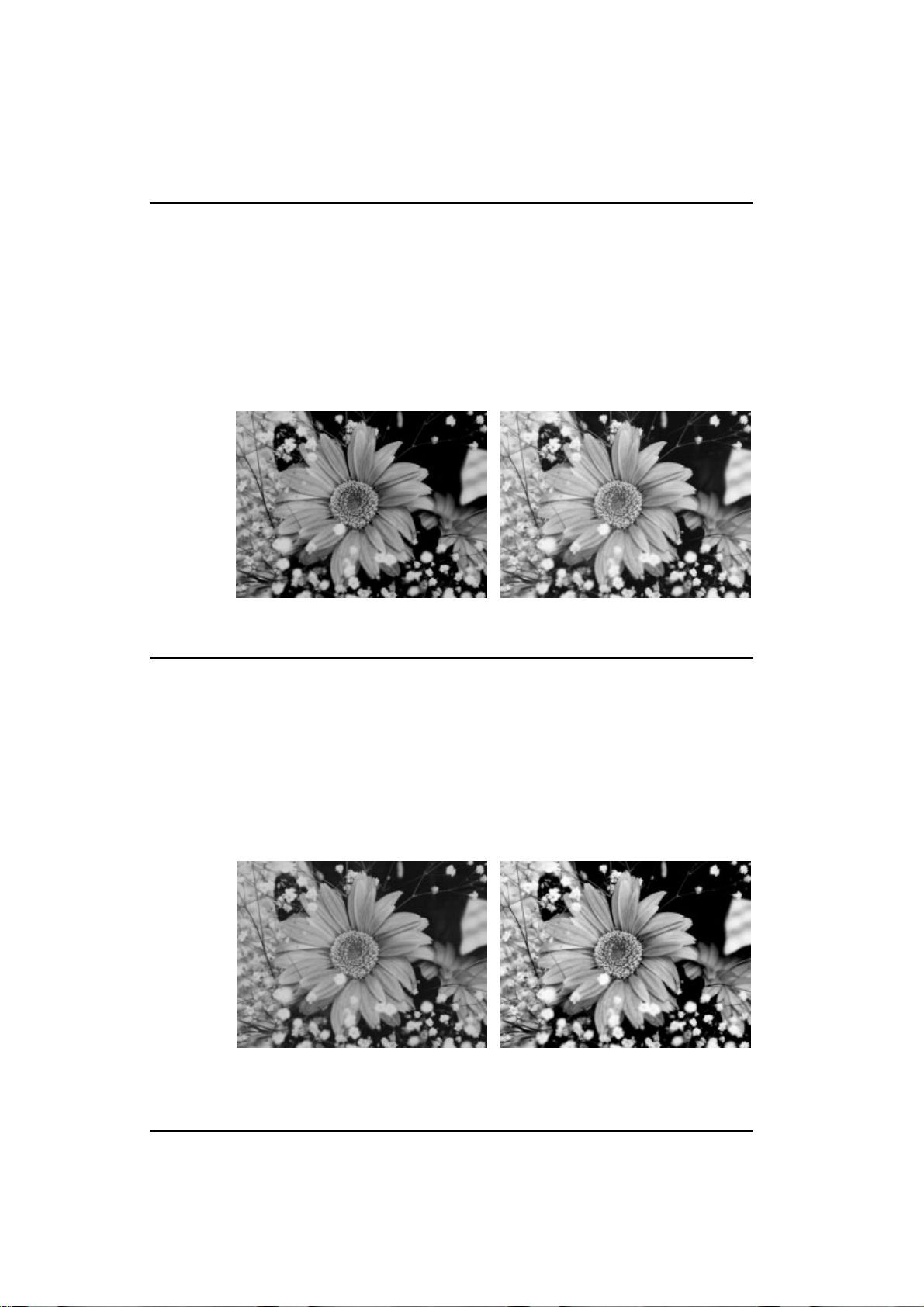
Image Scanner User's Manual
¡ Brightness
Function:
Usage:
To adjust the brightness value between 1 and 255.
A high brightness setting results in a lighter overall im age. A lo w br ightn ess sett ing
results in a darker overall image.
When scanning a dark image, the darker area may appear as deep black although it
has gray shades. In this case, increase the setting and shades of gray appear.
Conversely, if a lighter image becomes pure white, decrease the setting.
Lower Higher
¡ Contrast
Function:
Usage:
To adjust the contrast value between 1 and 255.
At a high contrast setting, the scanner emphasizes black and white, leaving few
middle gray shades. At a low contrast setting, the scanner emphasizes the middle
gray shades, at the expense of black and white.
If you want a sharp image, set a higher value. If you want a soft image, set a lower
value.
Lower
Higher
- 32 -
03_IS430-BODY 97.5.8, 5:37 PMPage 32 PageMaker 5.0J
Page 41
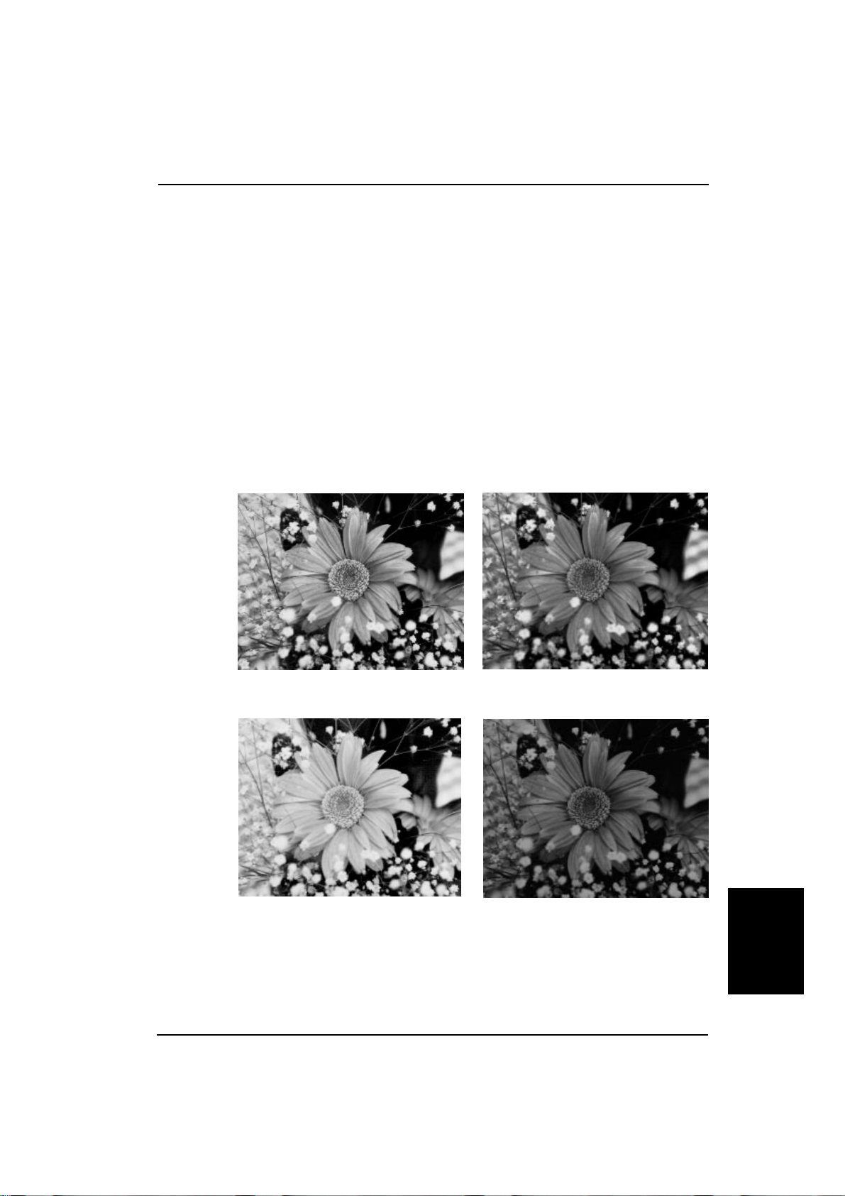
¡ Gamma correction
Image Scanner User's Manual
Function:
Usage:
To select following gamma correction settings:
Normal: Emphasizes contrast slightly to improve a scanned image.
Sharp: Emphasizes contrast to sharpen an image.
Smooth: Weakens contrast to soften an image.
Linear: Outputs an image as scanned.
User defined: Your own gamma correction curve is loaded into the scanner.
Select one of them depending on your original and output device.
If you want to correct an image finely, select the User defined setting to load your
own correction curve.
Normal
Smooth
Sharp
Linear
Appendix
- 33 -
03_IS430-BODY 97.5.8, 5:37 PMPage 33 PageMaker 5.0J
Page 42

Image Scanner User's Manual
¡ Binary filter
Function:
Usage:
You can use 4 binary filters; noise elimination, smoothing, thickening black lines
and edge extraction in binary scanning.
Noise elimination: Eliminates independent black or white dots.
Smoothing: Flattens uneven dots.
Thickening black lines: Thickens thin lines.
Edge extraction: Extracts outlines of the image.
For example, use filters at following cases.
Noise elimination: Use this filter when scaninng a document which is copied
several times. Blac k dot s in a whit e area an d whit e dots in a
black area will be eliminated.
not filtered filtered
Smoothing: If edges of a scanned image are uneven, scan it with this
filter again. Edges will be even.
- 34 -
not filtered
filtered
Thickening black lines: Use this filter when scanning thin lines or characters.
not filtered
filtered
Edge extraction: Use this filter if you need outlines of an image for design
etc.
not filtered filtered
03_IS430-BODY 97.5.8, 5:37 PMPage 34 PageMaker 5.0J
Page 43

Image Scanner User's Manual
¡ Parameter download
To download a gamma curve and a dither pattern to the scanner.
You can modify the scanned image with your gamma curve and binalize it with your dither
pattern.
Refer to your software manual for how to download these parameters to the scanner.
¡ Document size detection
The scanner detects th e width and length of a doc ument an d sends the m to the host co mputer .
Note:
E
Top and right areas (shadow areas
of the right figures) of an original
must be white. If these areas are colored, the size may not be detected
correctly.
E
Place an original on the contact
glass along the top and right scale.
Place originals on the document
table tightly against both sides
guides. If an original is not placed
correctly , the scanner may not de-
tect the size correctly.
Book mode
surface
a
b
5 mm
d
sub-scanning
direction
Document feeder mode
d
c
5 mm
surface
c
feeding direction
¡ Skew detection
To detect at what angle the document is skewed and to send the skew angle to the host
computer.
¡ Semi-automatic document feed (SADF) mode
d
c
5 mm
In this mode, orig inals which a re set on the fe eder one a t a time ar e auto matic ally f ed into the
document feeder and scanned one at a time.
- 35 -
03_IS430-BODY 97.5.8, 5:37 PMPage 35 PageMaker 5.0J
Appendix
Page 44

Image Scanner User's Manual
Options
¡ Red lamp unit
You can use the optional red lamp unit to skip the OCR red images.
Replace the lamp unit with the optional red lamp unit as follows.
Warning:
E
Never change the lamp unit with the scanner plugged in.
E
The lamp becomes very hot. Wait for about five minutes aftter turning the power off to let
the lamp cool off.
1. Initialize the scanner to return the carriage
to its original position.
2. Turn the power off and disconnect the
power cord.
3. Open the document feeder.
4. Remove the lamp cover.
5. Remove the connector cover.
6. Disconnect the connector.
2
3
1
7. Hold the right side of the lamp and pull it up
while sliding it to the left.
Caution:
Do not touch the middle of the lamp
unit. Hold the green parts only.
8. To attach the red lamp unit, go backwards
through the previous steps.
- 36 -
03_IS430-BODY 97.5.8, 5:37 PMPage 36 PageMaker 5.0J
Page 45

Image Scanner User's Manual
¡ Data compression unit
Using an optional data compression unit, it is possible to compress the scanned image data by
methods known as MH, MR, and MMR. This saves memory capacity.
¡ Video interface unit
The optional video interface unit provides a video interface connector.
¡ Image processing unit
The optional image processing unit adds the following image processing functions.
Dynamic threshold:
The scanned image is automatically binalized by an appropriate threshold. The scanner discriminates a background color and decides the threshold to use.
Auto photo/letter:
The scanner automatically de tects letter are as and photo ar eas of the origin al. The lette r areas
are scanned in binary, and the photo areas are scanned in halftone.
- 37 -
03_IS430-BODY 97.5.8, 5:37 PMPage 37 PageMaker 5.0J
Appendix
 Loading...