

Page 1

RUSSIAN-SC
(Machine Code: G412)
Service Manual
Issued on 27th December 2000
Ricoh Co., LTD
Page 2

!
IMPORTANT SAFETY NOTICES
1. Before disassembling or assembling parts of the scanner and peripherals,
make sure that the scanner power cord is unplugged.
2. The wall outlet should be near the scanner and easily accessible.
3. The output voltage of the PSU (Power Supply Unit) can be either 100 ~ 120
Vac or 220 ~ 240 Vac, without any adjustment. Make sure that the above
voltage is used.
4. The power cord should be an approved type, in accordance with the
regulations for the country in which the scanner is used.
5. The use of cables other than the shield I/O cables or specified equivalents
will invalidate the certification of this scanner and may cause interference
levels which exceed the limits established for this equipment.
6. When keeping used lithium batteries in order to dispose of them later, do not
put more than 100 batteries per sealed box. Storing larger numbers or not
sealing them apart may lead to chemical reactions and heat buildup.
Lithium Batteries (Memory Back-up)
!
CAUTION
The danger of explosion exists if a battery of this type is incorrectly
replaced.
Replace only with the same or an equivalent type recommended by the
manufacturer. Discard used batteries in accordance with the
manufacturer’s instructions.
Maintenance Information
The user’s manual explains how to use and maintain the scanner. Before
performing the maintenance, read the user’s manual.
Warning concerning copyright
Many documents are copyrighted. Such documents may not be reproduced by
scanning or in any other form without the express permission of the copyright
holder.
Notice
The contents of this manual are subject to change without notice.
1
Page 3

TABLE OF CONTENTS
1 INSTALLATION PROCEDURE.................................................... 1-1
1.1 INSTLLATION REQUIRMENTS................................................................1-1
1.1.1 ENVIRONMENT...............................................................................1-1
1.1.2 MACHINE LEVEL.............................................................................1-1
1.1.3 MINIMUM SPACE REQUIRMENTS.................................................1-1
1.1.4 POWER REQUIRMENT...................................................................1-1
1.2 MAINFRAME AND OPTION INSTALLATION PROCEDURES.................1-2
1.2.1 ACCESSORY CHECK......................................................................1-2
mainframe.............................................................................................1-2
IEEE1394 I/F (OPTION).......................................................................1-2
Network interface kit (OPTION)............................................................1-3
OIPUB (OPTION)..................................................................................1-3
Memory Card (Memory unit type B)......................................................1-3
2 PREVENTIVE MAINTENANCE SCHEDULE ............................... 2-1
2.1 USER MAINTENANCE .............................................................................2-1
3 REPLACEMENT AND ADJUSTMENT......................................... 3-1
3.1 SPECIAL TOOLS......................................................................................3-1
3.2 REPLACEMENT........................................................................................3-1
3.2.1 EXTERIOR.......................................................................................3-1
3.2.2 EXPOSURE GLASS.........................................................................3-2
3.2.3 INNER COVER 1..............................................................................3-2
3.2.4 ORIGINAL LENGTH 1/2 SENSORS.................................................3-3
3.2.5 SCANNER HP SENSOR AND DF POSITION SENSOR..................3-3
3.2.6 SENSOR BOARD UNIT (SBU).........................................................3-4
3.2.7 INNER COVER 2..............................................................................3-4
3.2.8 ORIGINAL WIDTH SENSOR............................................................3-5
3.2.9 EXPOSURE LAMP STABILIZER .....................................................3-5
3.2.10 SCANNER MOTOR........................................................................3-6
3.2.11 EXPOSURE LAMP.........................................................................3-7
3.2.12 AUTO DOCUMENT FEEDER (ADF)..............................................3-8
3.2.13 SCANNER FRAME.........................................................................3-8
3.2.14 SCANNER WIRE............................................................................3-9
3.2.15 POWER SUPPLY UNIT (PSU).....................................................3-10
3.2.16 SCANNER CONTROL UNIT (SCU).............................................3-10
3.2.17 VIDEO AND I/O CONTROL BOARD (VIOB)................................3-11
3.2.18 SCANNER OPERATION PANEL (SOP)......................................3-11
3.2.19 SWITCH BOARD (SWB)..............................................................3-12
3.3 ADJUSTMENT ........................................................................................3-13
3.3.1 SCANNER WIRE............................................................................3-13
Parallelism Adjustment.......................................................................3-13
Adjust points:......................................................................................3-13
i
Page 4

4 TROUBLESHOOTING................................................................. 4-1
4.1 LED FUNCTION MODE............................................................................4-1
4.1.1 NORMAL LED FUNCTION TABLE...................................................4-1
Order of priority.....................................................................................4-2
4.1.2 SELF DIAGNOSTIC MODE..............................................................4-2
LED function table ................................................................................4-2
Descriptions..........................................................................................4-3
4.1.3 BLOWN FUSE CONDITIONS ..........................................................4-4
4.1.4 IEEE1394 BOARD (OPTION)...........................................................4-4
5 SERVICE TABLES....................................................................... 5-1
5.1 DIP SWITCH FUNCTION..........................................................................5-1
5.1.1 DIP SWITCH COMBINATIONS........................................................5-1
DIP switch setting table (Normal mode)................................................5-1
DIP switch setting table (service level test mode).................................5-2
5.1.2 NORMAL MODE ..............................................................................5-2
5.1.3 ADF COUNTER, BOOK MODE COUNTER AND EXPOSURE LAMP
ON-TIME ....................................................................................................5-3
SCSI ID rotary switch............................................................................5-3
LED values ...........................................................................................5-3
Example: ...............................................................................................5-3
5.1.4 SENSOR TEST MODE.....................................................................5-4
5.1.5 FIRMWARE UPDATE PROCEDURE...............................................5-5
5.1.6 FLASH-ROM UPLOAD MODE.........................................................5-6
5.1.7 WHITE BALANCE ADJUSTMENT MODE........................................5-6
5.1.8 BOOK SIZE CHECK MODE.............................................................5-7
5.1.9 DEMONSTRATION MODE ..............................................................5-7
5.1.10 SELF DIAGNOSTIC MODE............................................................5-8
5.1.11 COMPONENT TEST MODE ..........................................................5-8
5.1.12 ADF SIZE CHECK MODE..............................................................5-8
5.1.13 EEPROM CLEAR MODE ...............................................................5-9
5.2 SERVICE PROGRAM MODE (WITH NIB OPTION) ...............................5-10
5.2.1 THE SP MODE DESCRIPTION .....................................................5-10
Entering the service mode..................................................................5-10
Density setup sample:.........................................................................5-10
Example: .............................................................................................5-10
5.3 NETWORK SETUP(WITH NIB OPTION)................................................5-11
5.3.1 NIB SETUP TABLE........................................................................5-11
Scanner function/Network table..........................................................5-11
Scanner function/configuration table...................................................5-11
5.3.2 NIB ERROR LOG DESCRIPTIONS...............................................5-11
rapp.....................................................................................................5-11
nas......................................................................................................5-12
SC related to the network interface card.............................................5-12
ORIGINAL SIZE SENSOR COMBINATION TABLE...........................5-13
ii
Page 5

6 DETAILED FUNCTION DESCRIPTIONS..................................... 6-1
6.1 MACHINE OVERVIEW..............................................................................6-1
6.2 CONTOROL SYSTEM BLOCK DIAGRAM................................................6-2
6.3 SCANNING................................................................................................6-3
6.3.1 OVERVIEW......................................................................................6-3
6.3.2 SCANNER DRIVE MECHANISM.....................................................6-4
6.3.3 IMAGE PROCESSING.....................................................................6-5
SBU and VIOB......................................................................................6-6
RIPU on SCU........................................................................................6-6
Line skipping correction........................................................................6-6
Scan line correction..............................................................................6-7
Black and white conversion..................................................................6-7
Gamma (γ) correction ...........................................................................6-7
Color resolution.....................................................................................6-7
Filtering.................................................................................................6-7
Magnification.........................................................................................6-8
Scale processing ..................................................................................6-8
Erasure of Irregular Dots.......................................................................6-8
OIPUB...................................................................................................6-8
Auto binary processing.........................................................................6-8
Auto image area separation..................................................................6-9
Manual image area separation .............................................................6-9
6.4 NEWORK INTERFACE.............................................................................6-9
6.5 IEEE1394 INTERFACE...........................................................................6-10
6.5.1 IEEE1394 .......................................................................................6-10
6.5.2 BLOCK DIAGRAM..........................................................................6-11
iii
Page 6

PERIPHERALS
ARDF
1 REPLACMENT............................................................................. 1-1
1.1 SPECIAL TOOLS......................................................................................1-1
1.2 REPLACEMENT........................................................................................1-1
1.2.1 LEFT COVER...................................................................................1-1
1.2.2 PAPER FEED UNIT..........................................................................1-2
1.2.3 SEPARATION ROLLER...................................................................1-2
1.2.4 PICK-UP ROLLER............................................................................1-3
1.2.5 FEED BELT......................................................................................1-3
1.2.6 ORIGINAL SET/ORIGINAL REVERSE SENSOR............................1-4
ORIGINAL LENGTH, WIDTH SENSOR BOARD..................................1-5
1.2.8 DF EXIT TABLE AND COVERS.......................................................1-6
1.2.9 FEED COVER SENSOR..................................................................1-6
1.2.10 REGISTRATION SENSOR.............................................................1-7
1.3 CLUTCH/SOLENOID/MOTORS................................................................1-8
DF Feed Clutch.....................................................................................1-8
Pick-up Solenoid...................................................................................1-8
Junction gate solenoid..........................................................................1-8
Transport Motor....................................................................................1-8
DF Feed Motor......................................................................................1-8
2 DETAILED FUNCTION DESCRIPTION....................................... 2-1
2.1 MACHINE OVERVIEW .............................................................................2-1
2.1.1 MECHANICAL COMPONENT LAYOUT...........................................2-1
Mechanical component layout ..............................................................2-1
Drive layout...........................................................................................2-2
2.1.2 CONTROL SYSTEM........................................................................2-3
2.2 DETAILED FUNCTION .............................................................................2-4
2.2.1 ORIGINAL SIZE DETECTION..........................................................2-4
2.3 SERVICE TABLE ......................................................................................2-5
2.3.1 ORIGINAL SIZE SENSOR AND BOARD COMBINATION...............2-5
2.3.2 PICK-UP AND SEPARATION ..........................................................2-7
2.3.3 ORIGINAL TRANSPORT AND EXIT................................................2-8
Single –sided originals..........................................................................2-8
Double-side originals ............................................................................2-9
2.3.4 TIMMING CHARTS........................................................................2-10
Single-sided mode (not pre-feed, not thin paper)................................2-10
Single-sided mode (pre-feed, not thin paper)......................................2-11
Single-sided mode (pre-feed, thin paper)............................................ 2-12
Double-sided mode (not pre-feed)......................................................2-13
Jam Conditions...................................................................................2-14
iv
Page 7

SERVICE TOOL
1 OVERALL INFORMATION ..............................................................1
1.1 OPERATIVE CONDITIONS .........................................................................1
1.2 INITIAL SETTINGS ......................................................................................1
1.2.1 SCSI ID................................................................................................1
1.2.2 HOST ADAPTER ID............................................................................2
1.3 CHART SETTING POSITION.......................................................................3
1.3.1 RICOH GRAY SCALE.........................................................................3
1.3.2 RS-13 ..................................................................................................3
2 SCAN...............................................................................................4
2.1 SIMPLE SCANNING ....................................................................................4
2.1.1 OVERVIEW.........................................................................................4
2.1.2 SCANNING..........................................................................................5
2.1.3 SCANNING A SELECTED AREA........................................................7
2.2 SCANNING BY MANUAL SETTING ............................................................8
2.3 CONTINUOUS SCANNING..........................................................................9
3 SCANNING ADJUSTMENT...........................................................10
3.1 OVERVIEW................................................................................................10
3.2 SCAN COUNTER.......................................................................................10
3.3 REGISTRATION.........................................................................................11
3.4 WHITE AND GRAY BALANCE...................................................................12
3.4.1 WHITE BALANCE.............................................................................12
Manual adjustment ................................................................................12
Automatic adjustment............................................................................13
3.4.2 GRAY BALANCE ADJUSTMENT......................................................14
3.5 DESTINATION ...........................................................................................16
4 IMAGE EVALUATION....................................................................17
4.1 OVERVIEW................................................................................................17
4.2 REGISTRATION.........................................................................................18
4.2.1 PROCEDURE....................................................................................18
4.2.2 SPECIFIED VALUE...........................................................................19
Book mode.............................................................................................19
ADF mode(front side).............................................................................19
ADF mode(reverse side)........................................................................19
4.2.3 CONDITION ......................................................................................19
4.2.4 METHOD...........................................................................................19
Main scan ..............................................................................................19
Sub scan................................................................................................19
4.3 SKEW.........................................................................................................20
4.3.1 PROCEDURE....................................................................................20
4.3.2 SPECIFIED VALUE...........................................................................20
Book mode.............................................................................................20
ADF mode..............................................................................................20
4.3.3 CONDITION ......................................................................................21
v
Page 8

4.3.4 METHOD...........................................................................................21
Main scan ..............................................................................................21
Sub scan................................................................................................21
4.4 ACTUAL IMAGE SIZE................................................................................22
4.4.1 PROCEDURE....................................................................................22
4.4.2 SPECIFIED VALUE...........................................................................22
Book mode.............................................................................................22
ADF mode..............................................................................................22
4.4.3 CONDITION ......................................................................................23
4.4.4 METHOD...........................................................................................23
Main scan ..............................................................................................23
Sub scan................................................................................................23
4.5 JITTER.......................................................................................................24
4.5.1 PROCEDURE....................................................................................24
± 45 degrees..........................................................................................24
0 degree.................................................................................................25
4.5.2 SPECIFIED VALUE...........................................................................26
4.5.3 CONDITION ......................................................................................26
4.5.4 METHOD...........................................................................................26
± 45 degrees..........................................................................................26
0 degrees...............................................................................................26
4.6 PARTIAL IMAGE STRETCH......................................................................27
4.6.1 PROCEDURE....................................................................................27
4.6.2 SPECIFIED VALUE...........................................................................27
Book mode.............................................................................................27
ADF mode..............................................................................................27
4.6.3 CONDITION ......................................................................................28
4.6.4 METHOD...........................................................................................28
5 TROUBLESHOOTING...................................................................29
5.1 ERROR MASSEGE ....................................................................................29
5.1.1 ON START UP ..................................................................................29
5.1.2 ADJUSTMENT AND SCANNING......................................................30
5.1.3 IMAGE EVALUATIONS.....................................................................30
5.2 SCSI CONDITION CODES........................................................................31
5.2.1 SENSE KEY CODES.........................................................................31
5.2.2 ADDITIONAL SENSE CODES AND QUALIFIRE..............................31
vi
Page 9
28 December, 2000 INSTLLATION REQUIRMENTS
1. INSTALLATION PROCEDURE
1.1 INSTLLATION REQUIRMENTS
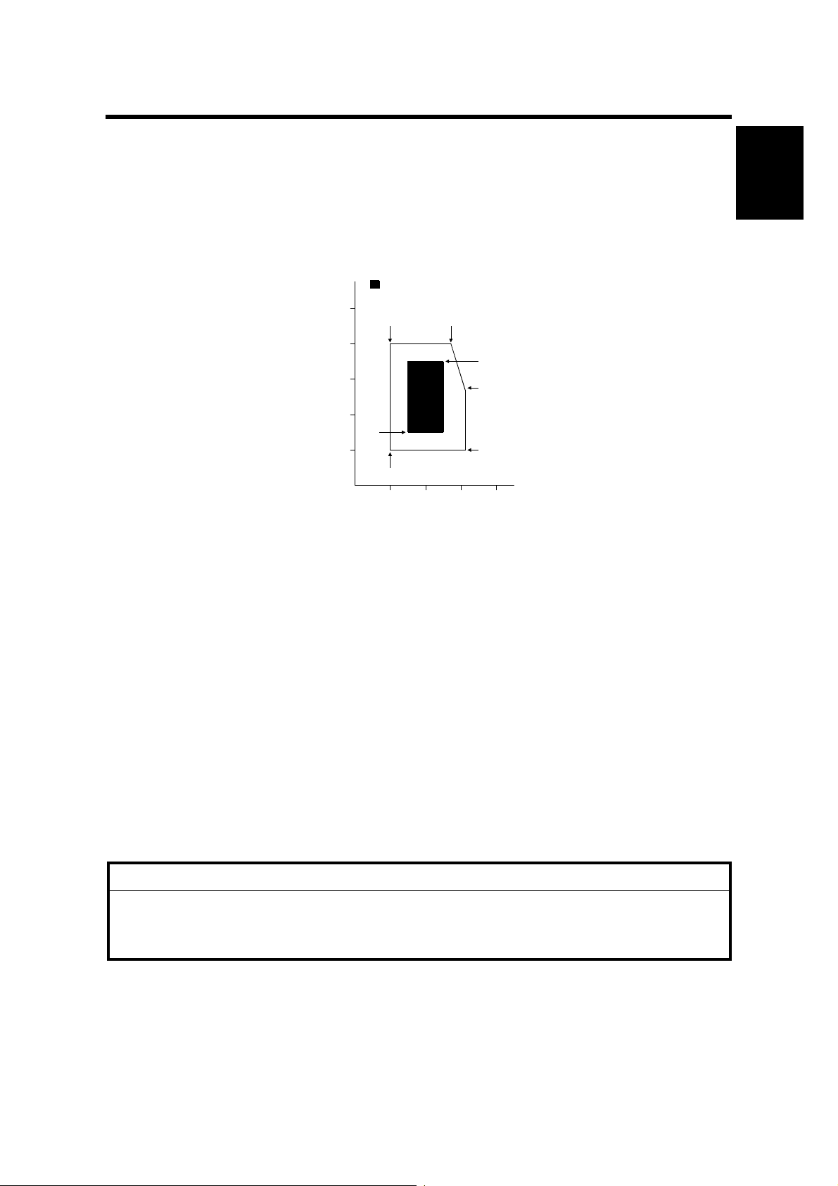
1.1.1 ENVIRONMENT
Use this machine at optimum temperature and moisture.
: Optimum temperature and moisture range
100
10°C 80% 27°C 80%
80
25°C 70%
60
Moisture [%]
40
20
15°C 30%
10°C 20%
10 20 30 40
Temperature [°C]
32°C 54%
32°C 20%
G412I500.WMF
1.1.2 MACHINE LEVEL
Front to back within ±5 mm of level
Right to left ±5 mm of level
Installation
1.1.3 MINIMUM SPACE REQUIRMENTS
Right clearance: Over 0 mm
Left clearance: Over 100 mm
Back side clearance: Over 0mm
Top clearance: Over 660 mm
1.1.4 POWER REQUIRMENT
!
CAUTION
1. Make sure the plug is firmly inserted in the outlet
2. Avoid multi-wiring.
3. Be sure to ground machine.
North America: Input voltage AC102V to 138V, less than 4.0A, 45 to 65Hz
Europe: Input voltage AC187V to 276V, less than 2.0A, 45 to 65Hz
Do not set anything on the power cord.
1-1
Page 10

MAINFRAME AND OPTION INSTALLATION PROCEDURES 28 December, 2000
1.2 MAINFRAME AND OPTION INSTALLATION PROCEDURES
1.2.1 ACCESSORY CHECK
NOTE: NA is North America. EU is Europe.
mainframe
NA EU
Product code G412-17 G412-27
Terminator Yes (Internal) Yes (Internal)
SCSI Cable No No Note1)
Power Cable Yes Yes (C Type)
Screwdriver Yes Yes
Installation Procedure/ packaging contents Yes Yes
Safety instruction sheet (19 languages) No Y es
Safety instruction sheet for US Yes No
CD-ROM
Operating instruction for SCSI and
IEEE1394 (7 languages)
TWAIN Driver SCSI I / F (7 languages) Yes Note 3) Yes Note 3)
TWAIN Driver IEEE1394 I/F
(7 languages)
DeskTopBinder V2 Lig ht (14 languages) Yes Note 4) Yes Note 4)
DeskTopBinder V2 Lig ht Manual
(PDF file)
Yes Note 2) Yes Note 2)
Yes Note 3) Yes Note 3)
Yes Yes
NOTE: 1) SCSI cable is removed from 220V model.
2) Operating instruction will be provided with PDF format. No paper
manual is bundled.
3) TWAIN driver will be generic.
4) Schedule for releasing bundled drivers and utility is mentioned in the
cause of “ Schedule”.
IEEE1394 I/F (OPTION)
NA/EU
Product code G562-17
IEEE1394 board Yes
IEEE1394 cable Yes
Screws (2 pieces) Yes
Installation procedure Yes
1-2
Page 11

28 December, 2000 MAINFRAME AND OPTION INSTALLATION PROCEDURES
Network interface kit (OPTION)
NA/EU
Product code G558-17
Network interface Yes
Operation panel + Screw s Yes
Screw (2 Pieces) Yes
Installation procedure (7 lang uages) Yes
CD-ROM
TWAIN driver for Network I/F by
Ricoh (7 languages)
Scanrouter V2 (5 languages) Yes
Operating instructions Yes
Aficio manager Yes
Aficio manager for client Yes
WebStatusMo nit or He lp Yes
Yes
OIPUB (OPTION)
NA/EU
Product code G514-21
Installation procedure Yes
Installation
NOTE: Use for Image processing unit to following processing. (monochrome
image only)
• Auto binary processing
• Auto Image area separation
• Manual Image area separation
Memory Card (Memory unit type B)
NA/EU
32M SDRAM G578-17
64M SDRAM G579-17
128M SDRAM G580-17
NOTE: Increases the data capacity. Faster image reading.
1-3
Page 12

28 December, 2000 USER MAINTENANCE
2. PREVENTIVE MAINTENANCE SCHEDULE
2.1 USER MAINTENANCE
Clean the following parts at every EM.
Item Remarks
Feed belt Wipe out wet cloth at alcohol or w at er.
Pick-up roller Wipe out wet cloth at alcohol or water.
Separation roller Wipe out wet cloth at alcohol or wat er.
Preventive
Maintenance
2-1
Page 13
28 December, 2000 SPECIAL TOOLS
3. REPLACEMENT AND AD JUSTMENT
!
CAUTION
Turn off the main power switch and unplug the machine before attempting
any of the procedures in this section.
CAUTION: To prevent injury, do not change the position of bule screw. They are
used in position where customer may touch them.
This manual uses the following .
☛: See or Refer to !: Screw ": Connector
3.1 SPECIAL TOOLS
Part number Description Description section Qty
A0069104 Scanner position pin (4pcs/set) 3.3.1 SCANNER WIRE 1
A2309350 Flash memory card 4MB
G4129310 Ricoh Gray Scale SERVICE TOOL 1
G4049004 RS-13 A3 55kg
3.3.2 FIRM WARE U PDATE
PROCEDURE
3.2.6 SENSOR BOARD UNIT,
3.2.11 EXPOUSURE L AMP
3.2 REPLACEMENT
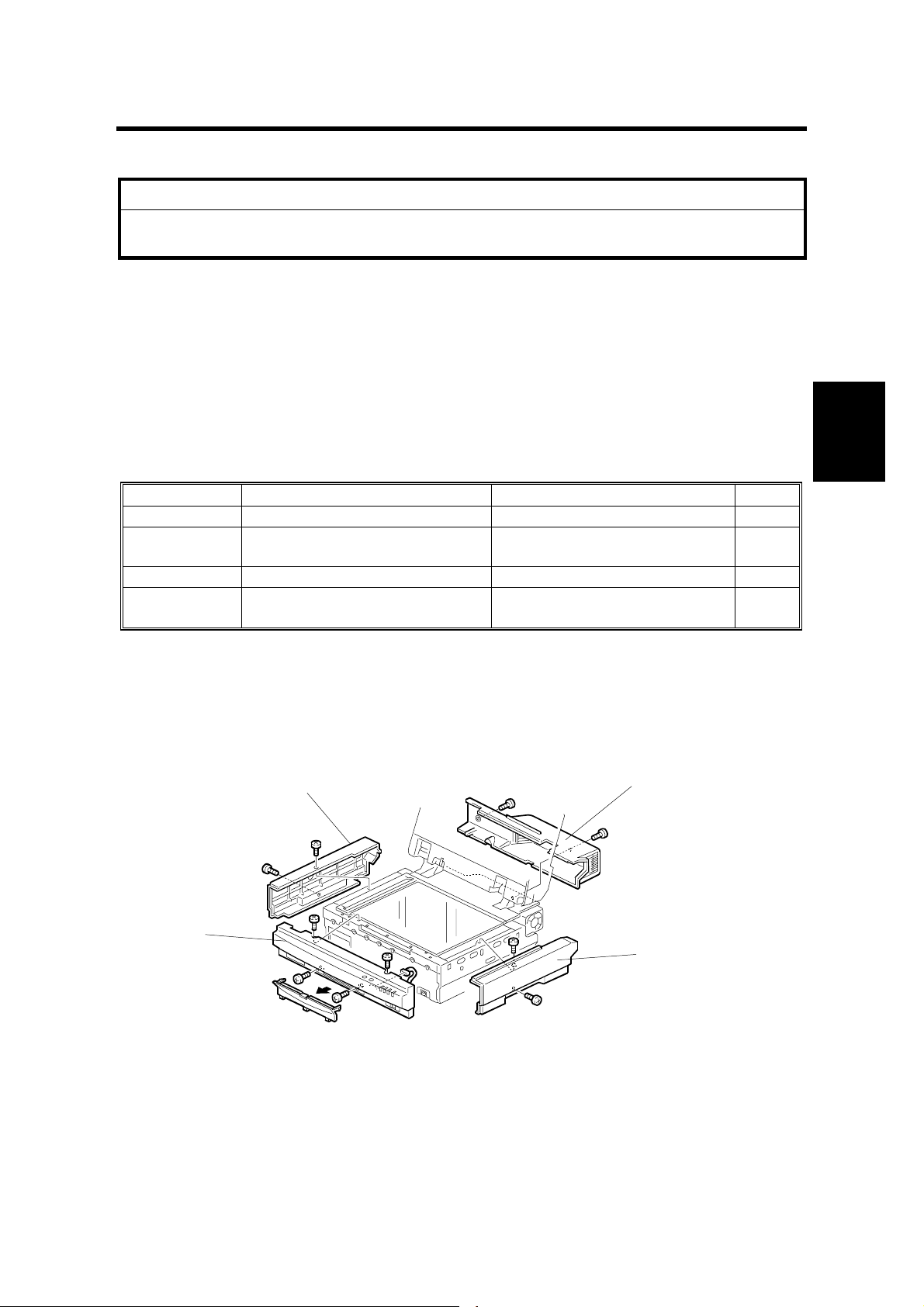
3.2.1 EXTERIOR
[B]
[D]
Adjustment
Replacement
1
1
[A]
[A]: Front cover (!x4, "x1)
[B]: Left cover (!x2)
[C]: Right cover (!x2)
[D]: Rear cover (!x2)
[C]
G412R001.WMF
3-1
Page 14
REPLACEMENT 28 December, 2000
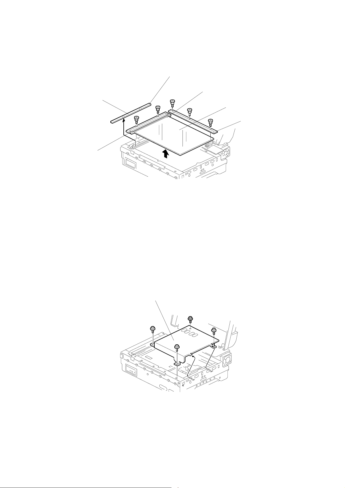
3.2.2 EXPOSURE GLASS
White Mark
Red Mark
[D]
[C]
[A]
[B]
G412R002.WMF
[A]: Rear scale(!x3)
[B]: Left scale (!x2)
[C]: Exposure glass
[D]: ADF exposure glass
CAUTION: 1) Use caution when placing the red mark position on the exposure
glass [C].
2) Use caution when placing the white mark position on the ADF
exposure glass [D].
3.2.3 INNER COVER 1
[A]
G412R003.WMF
Exposure glass (☛ 3.2.2)
[A]: Inner cover (!x4)
3-2
Page 15
28 December, 2000 REPLACEMENT
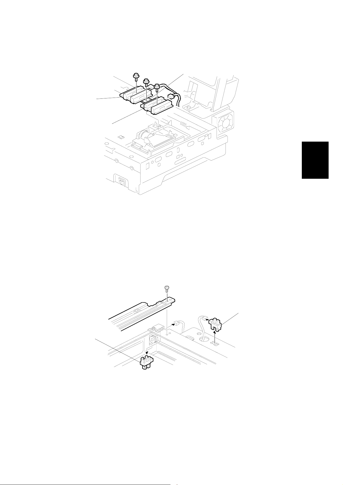
3.2.4 ORIGINAL LENGTH 1/2 SENSORS
[C]
[B]
[A]
G412R500.WMF
Adjustment
Replacement
Exposure glass (☛ 3.2.2)
Inner cover 1 (☛ 3.2.3)
[A]: Original Length 1 sensor (!x1, "x1)
[B]: Original Length 2 sensor (!x1, "x1)
[C]: Original Length sensor bracket (!x1)
3.2.5 SCANNER HP SENSOR AND DF POSITION SENSOR
[B]
[A]
A193R015.WMF
Left and Rear cover (☛ 3.2.1 EXTERIOR)
Motor cover (☛ 3.2.10 SCANNER MOTOR)
[A]: Scanner HP sensor ("x1)
[B]: DF position sensor ("x1)
3-3
Page 16
REPLACEMENT 28 December, 2000
3.2.6 SENSOR BOARD UNIT (SBU)
[A]
G412R007.WMF
Exposure glass (☛ 3.2.2)
Inner cover 1 (☛ 3.2.3)
Original Length 1/2 sensors (☛ 3.2.4)
[A]: SBU (!x4,"x1)
CAUTION: Do not dismantle this unit. Take out the screw at the bracket only.
NOTE: After SBU has been replaced, adjust the registration using Scan-Probe (the
PC utility software for this machine) if necessary.
3.2.7 INNER COVER 2
[A]
G412R005.WMF
Exposure glass (☛ 3.2.2)
Inner cover 1 (☛ 3.2.3)
Original Length 1/2 sensors (☛ 3.2.4)
SBU (☛ 3.2.6)
[A]: Inner cover 2 (!x3)
3-4
Page 17
28 December, 2000 REPLACEMENT
3.2.8 ORIGINAL WIDTH SENSOR
Exposure glass (☛ 3.2.2)
Inner cover 1 (☛ 3.2.3)
Original Length 1/2 sensors (☛ 3.2.4)
SBU (☛ 3.2.6)
Inner cover 2 (☛ 3.2.7)
[A]: Original Width 3 Sensor (!x1)
3.2.9 EXPOSURE LAMP STABILIZER
Exposure glass (☛ 3.2.2)
Inner cover 1 (☛ 3.2.3)
Original Length 1/2 sensors (☛ 3.2.4)
[A]
[A]
G412R006.WMF
Adjustment
Replacement
SBU (☛ 3.2.4)
Inner cover 2 (☛ 3.2.7)
Original Width sensor (☛ 3.2.8)
[A]: Exposure lamp stabilizer (!x2, "x2)
G412R021.WMF
3-5
Page 18
REPLACEMENT 28 December, 2000
3.2.10 SCANNER MOTOR
[A]
G412R008.WMF
[B]
[D]
[A]: Motor cover (!x2)
[B]: Scanner motor bracket(!x2,"x2)
[C]: Timing belt (!x1)
[D]: Scanner motor (!x2)
[C]
G412R009.WMF
3-6
Page 19
28 December, 2000 REPLACEMENT
3.2.11 EXPOSURE LAMP
[A]
G412R006.WMF
Adjustment
Replacement
[B]
G412R013.WMF
Front cover (☛ 3.2.1 EXTERIOR)
Exposure glass (☛ 3.2.2)
Move carriage to the notch [A] on the front frame.
[B]: Exposure lamp (!x1, "x1)
NOTE: After replacing the exposure lamp, adjust the scanning image using Scan-
Probe (the PC utility software for this machine) if necessary.
3-7
Page 20
REPLACEMENT 28 December, 2000
3.2.12 AUTO DOCUM ENT FEEDER (ADF)
[A]
G412R010.WMF
Exposure glass (☛ 3.2.2)
Inner cover 1 (☛ 3.2.3)
Original Length 1/2 sensors (☛ 3.2.4)
SBU (☛ 3.2.6)
[A]: ADF (!x2, "x3,earth wirex1)
3.2.13 SCANNER FRAME
[A]
[B]
[D]
[C]
G412R012.WMF
Front cover (☛ 3.2.1 EXTERIOR)
Exposure glass (☛ 3.2.2)
[A]: Left frame (!x3)
[B]: Front frame (!x5)
[C]: Hinge (!x3)
[D]: Rear frame (!x2)
3-8
Page 21

28 December, 2000 REPLACEMENT
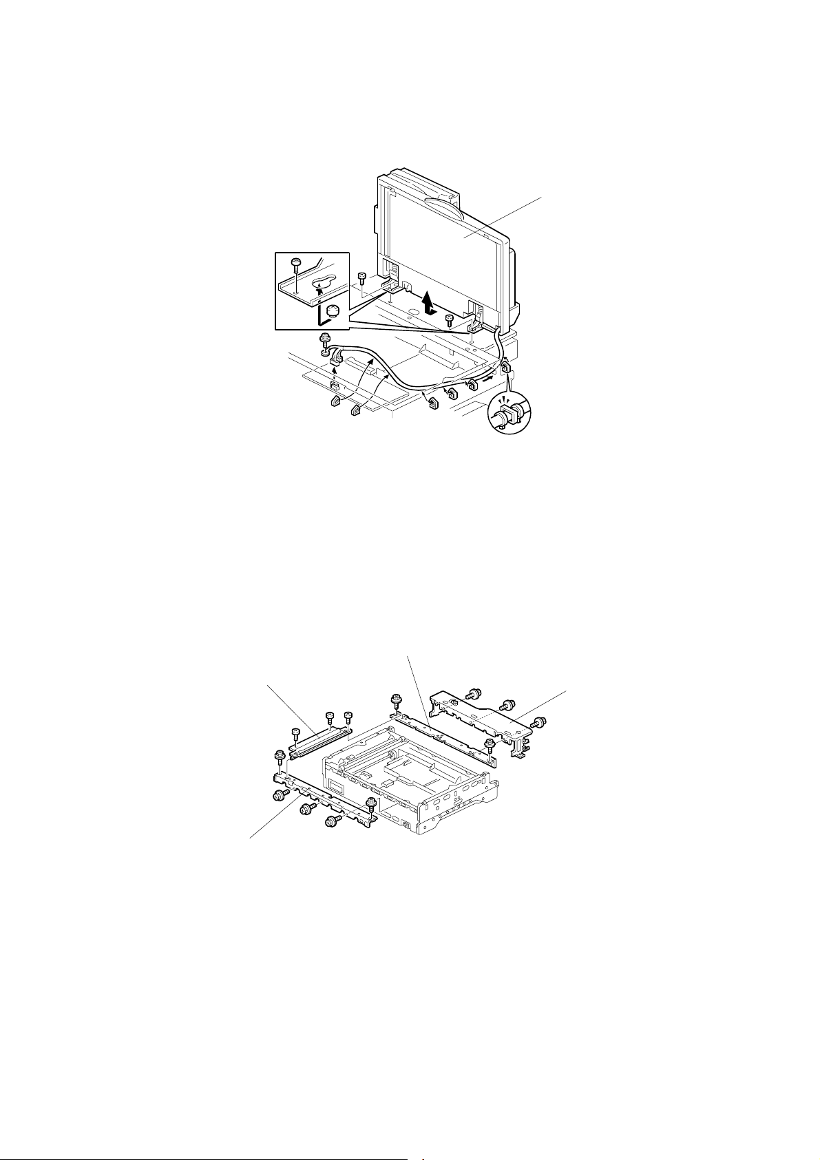
3.2.14 SCANNER WIRE
[F]
[H]
[D]
[G]
G412R504.WMF
[A]
Exterior covers (☛ 3.2.1)
Exposure glass (☛ 3.2.2)
ADF (☛ 3.2.12)
Scanner frames (☛3.2.13)
[B]
[J]
[C]
[I]
[E]
G412R015.WMF
Adjustment
Replacement
Uninstall:
[A]: Right or left scanner wire tension bracket (!x1)
[B]: Wire stopper bracket (!x1)
[C]: Tension spring
[D]: Scanner wire and scanner drive pulley (allen screw x1)
Install:
Wind the new scanner wire around scanner drive pulley in the correct direction, as
shown [E].
Wind the new scanner wire with the ball around the upper left pulley as shown [F].
Wind the new scanner wire with the ball through the central pulley as shown [G].
Hook the wire ball to the frame [H].
Wind the new scanner wire with the ring around the right pulley as shown [I].
Attach the new scanner wire to the scanner [J] .(!x1)
Wind the new scanner wire with the ring through the central pulley as shown [G].
Install the tension spring [C] on the wire tension bracket [A].(!x1)
Adjust scanner frame wire (☛ 3.3.1 SCANNER WIRE)
Tighten the wire tension bracket [A].
3-9
Page 22
REPLACEMENT 28 December, 2000
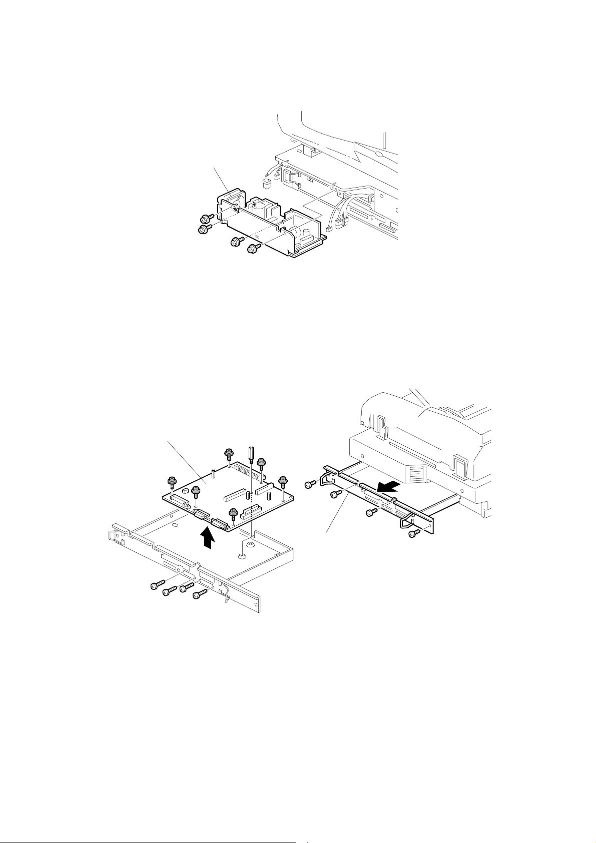
3.2.15 POWER SUPPLY UNIT (PSU)
[A]
G412R011.WMF
Rear cover (☛ 3.2.1 EXTERIOR)
[A]: PSU (!x4, "x4)
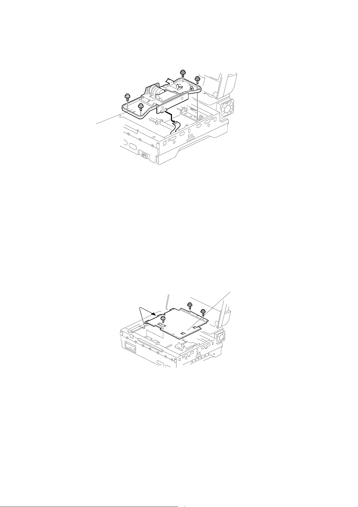
3.2.16 SCANNER CONTROL UNIT (SCU)
[B]
[A]
G412R019.WMF
G412R018.WMF
[A]: SCU assembly (!x4)
[B]: SCU (!x10, spacerx4)
NOTE: 1) Check the connection with the VIOB, if necessary.
2) After the SCU has been replaced, remove the EEPROM from the old
board and put on the new board.
3-10
Page 23

28 December, 2000 REPLACEMENT
3.2.17 VIDEO AND I/O CONTROL BOARD (VIOB)
[A]
G412R020.WMF
Exposure glass (☛ 3.2.2)
Inner cover 1 (☛ 3.2.2)
Original Length 1/2 sensors (☛ 3.2.4)
SBU (☛ 3.2.4)
Inner cover 2 (☛ 3.2.6)
[A]: VIOB (!x6, "x11)
NOTE: Check the connection with the SCU, if necessary.
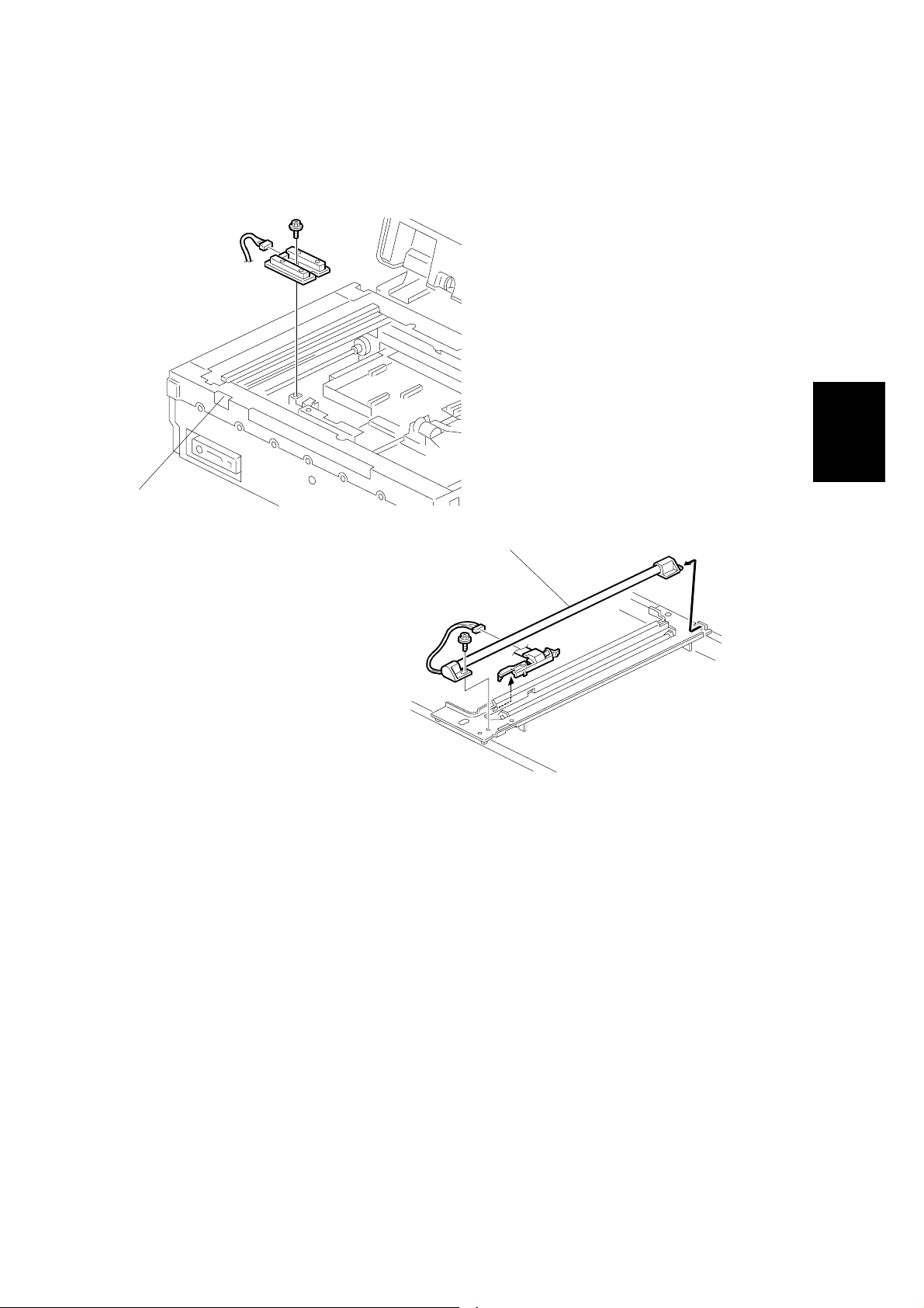
3.2.18 SCANNER OPERATION PANEL (SOP)
[A]
Adjustment
Replacement
Front covers (☛ 3.2.1 EXTERIOR)
[A]: SOP (!x1)
G412R023.WMF
3-11
Page 24
REPLACEMENT 28 December, 2000
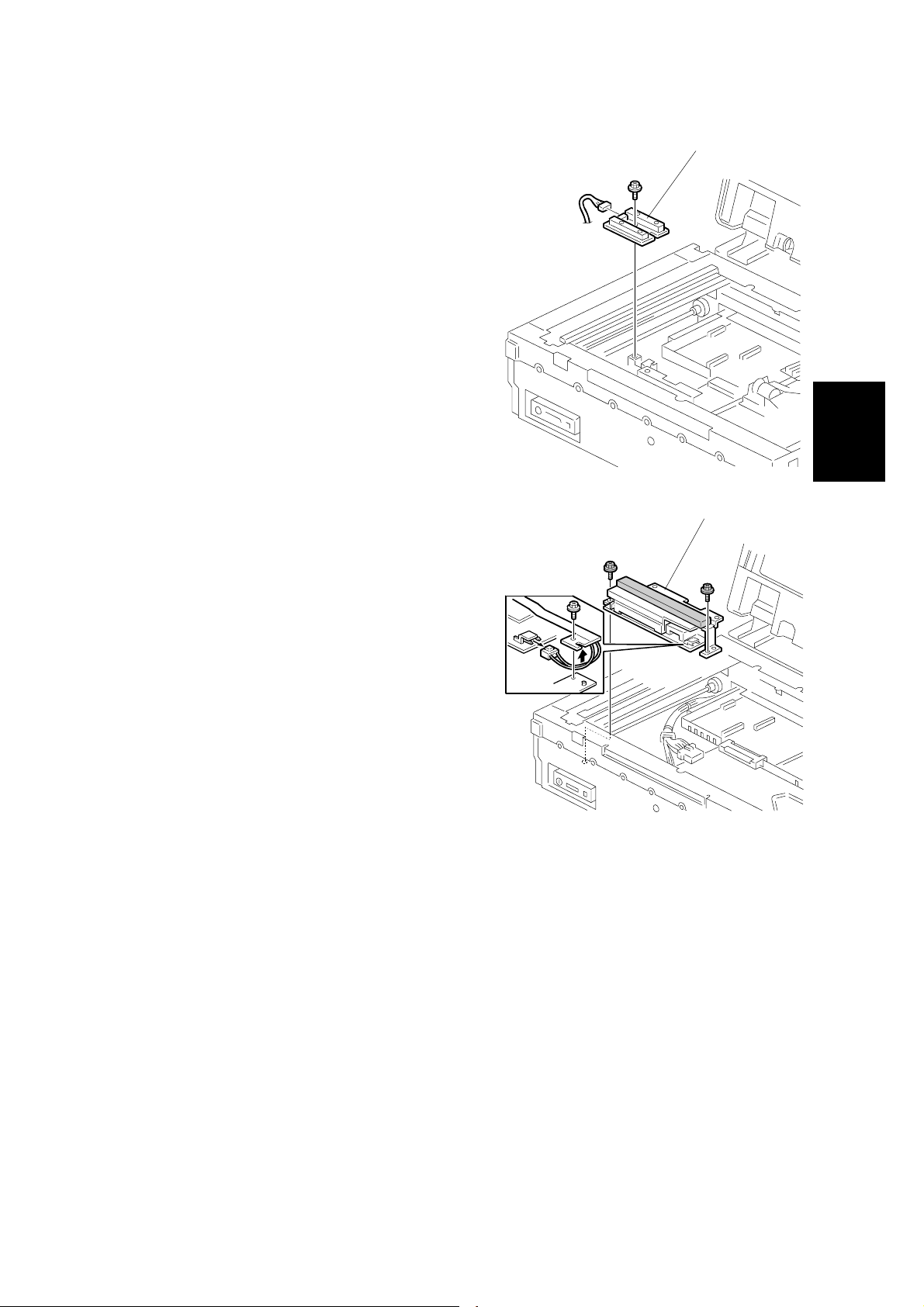
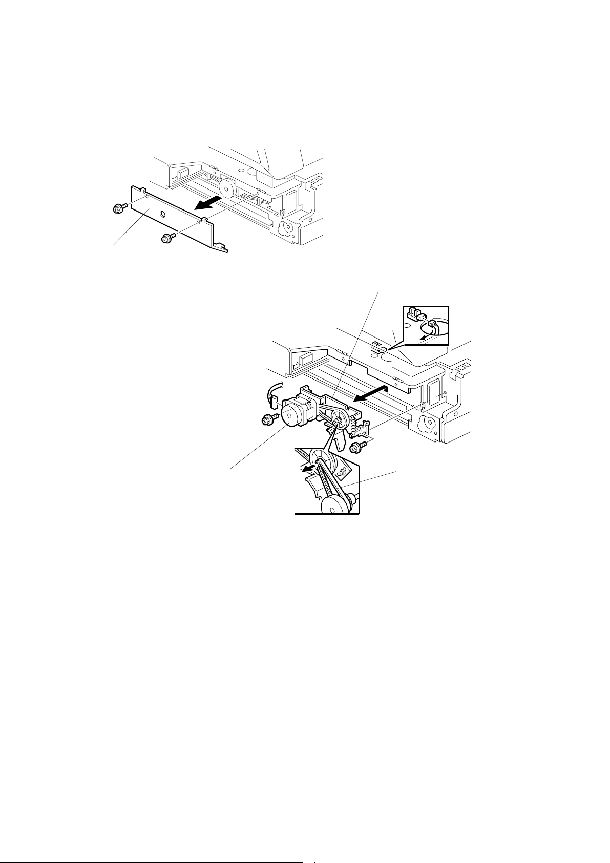
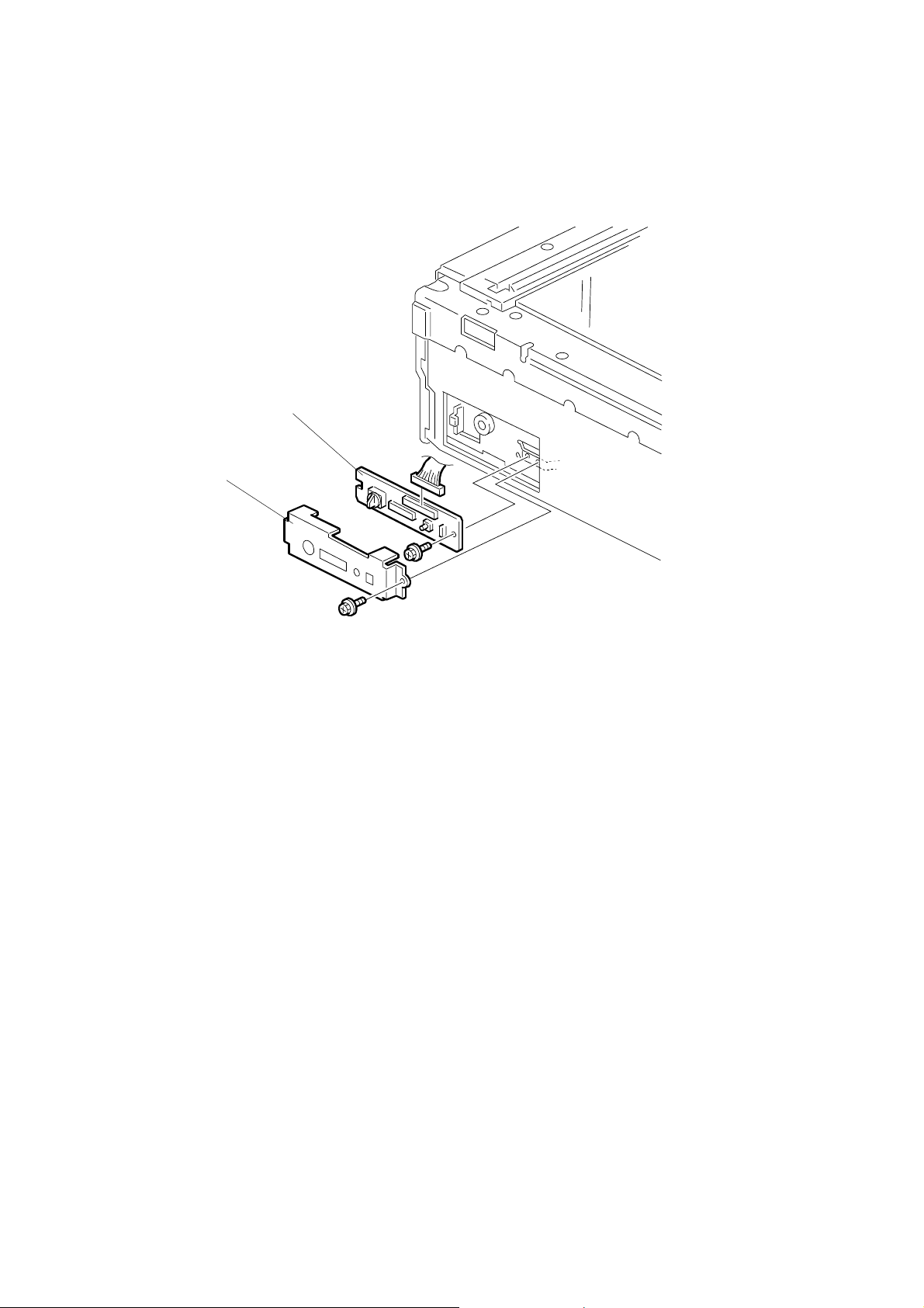
3.2.19 SWITCH BOARD (SWB)
[B]
[A]
Front covers (☛ 3.2.1 EXTERIOR)
[A]: Gird cover (!x1)
[B]: SWB (!x1,"x1)
NOTE: Keep following setting.
• SCSI ID
• Dip switch
• SCSI/IEEE1394 Switch
G412R022.WMF
3-12
Page 25
28 December, 2000 ADJUSTMENT
3.3 ADJUSTMENT
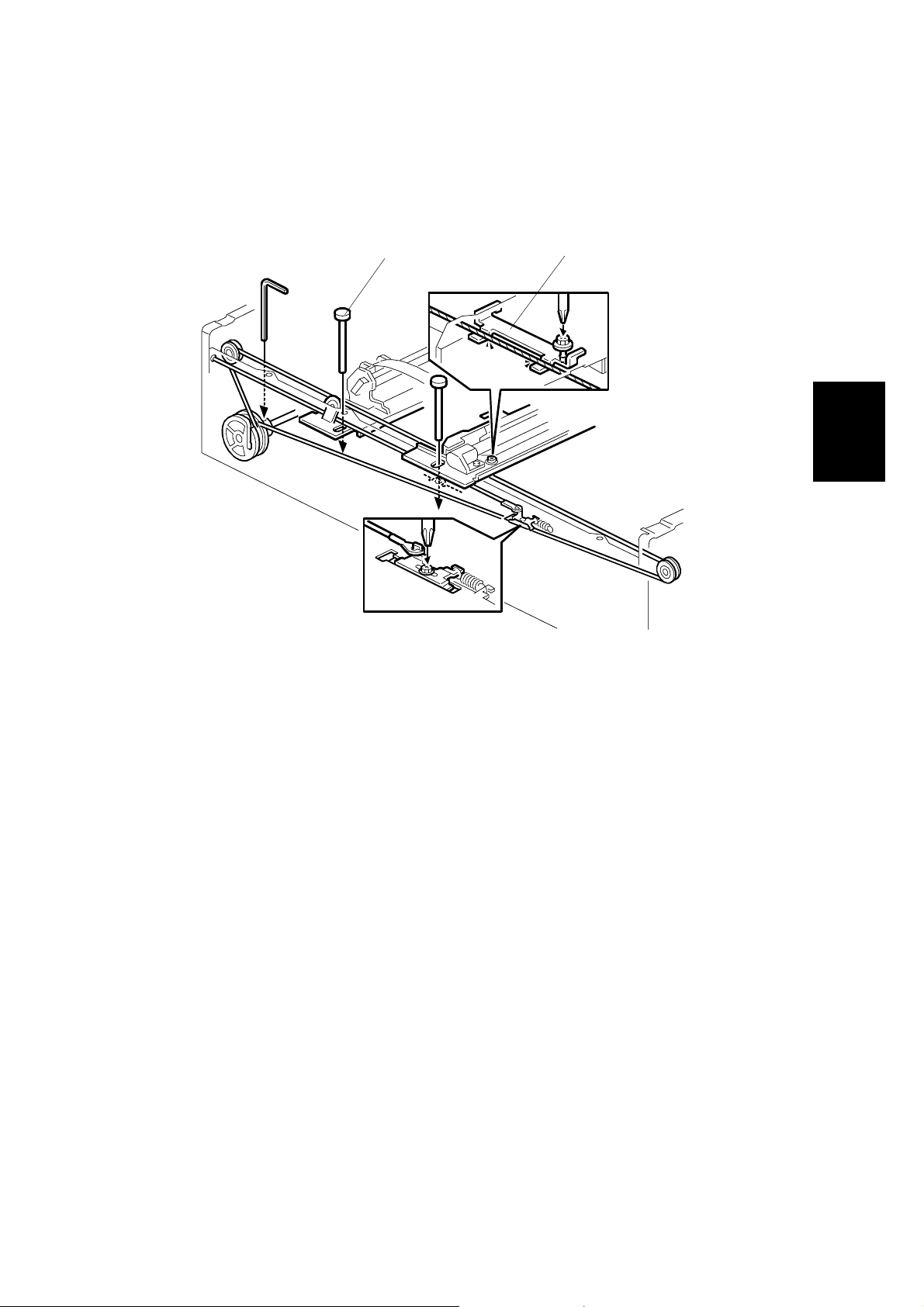
3.3.1 SCANNER WIRE
Parallelism Adjustment
[A]
[B]
G412R014.WMF
Adjustment
Replacement
Exterior covers (☛ 3.2.1)
Exposure glass (☛ 3.2.2)
ADF (☛ 3.2.12)
Scanner frames (3.2.13)
[A]: Set scanner positioning tools (P/N A0069104)
If scanner position tool does not install smoothly, it needs adjusting.
Adjust points:
1) Check the scanner drive pulley position.
2) Check the wire stopper bracket.
3) Adjust the scanner frame wire.
3-13
Page 26

28 December, 2000 LED FUNCTION MODE
4. TROUBLESHOOTING
4.1 LED FUNCTION MODE
4.1.1 NORMAL LED FUNCTION TABLE
Conditions Contents
Machine
initialization
Stand-by
Scanning Normal mode
User-visible
error
conditions
Service-call
error
Low power
mode
Flash-ROM
download
Flash-ROM
upload
Flash-ROM
download
error
Flash-ROM
upload error
Overall
machine check
Normal mode
Scan wait
mode
ADF cover switch open On
Document jam On
Document misfeed On
Option error Blinking Blinking On Blinking
Originals
on the
ADF
-OnOnOnOn
No On Off Off Off
Yes On Off On Off
No On Off Blinking Off
Yes On Off Blinking Off
No On On Off Off
Yes On On On Off
- Blinking Blinking Blinking Blinking
-BlinkingOff
- NOTE 2)
- NOTE 3)
- Off Off Blinking Blinking
- Off Blinking Blinking Blinking
Power on
(Green)
Machine
NOTE 4)
NOTE 4)
NOTE 4)
LEDs
busy
(Green)
On
On
On
Document
in place
(Green)
Off On
Blinking On
On On
Off
NOTE 1)
Error
(Red)
Off
Trouble-
shooting
On: LED on Blinking: LED blinking Off: LED off
NOTE: 1) When the mode changes to the scan wait mode, it starts blinking.
2) On LEDs scroll to the left.
3) On LEDs scroll to the right.
4) When the scanner moves back to ho me position, it turns off.
4-1
Page 27

LED FUNCTION MODE 28 December, 2000
Order of priority
1) Flash-ROM upload error
2) Flash-ROM download error
3) Flash-ROM upload
4) Flash-ROM download
5) Service-call error
6) User-visible error - ADF cover switch open
7) User-visible error - Document jam
8) User-visible error - Document misfeed
9) User-visible error - Op tion error
10) Machine Initialization
11) Stand-by - Scan wait mode
12) Stand-by - Originals on the ADF
13) Low power mode
14) Stand-by - Normal mode
4.1.2 SELF DIAGNOSTIC MODE
By setting the proper DIP switch, you can view the specific error when a service
call error is received. (☛ 5.1 DIP SW ITCH FUNCTION)
LED function table
LEDs
Conditions
Power on
(Green)
Memory error Blinking Off Off Off
IEEE1394 3.3V error Blinking On Blinking Blinking
VIOB 3.3V error Blinking Off Blinking Blinking
OIPU 3.3V error Blinking On Off Blinking
SCU 2.5V error Blinking Off On Blinking
SCU 3.3V error Blinking Off Off Blinking
Lamp failure error Blinking Blinking On On
Home position error Blinking Blinking Blinking On
NIC SC error Blinking Blinking Blinking Blinking
On: LED on Blinking: LED blinking Off: LED off
Machine
busy
(Green)
Document
in place
(Green)
Error (Red)
NOTE: 1) When t wo or more errors occu r, the LEDs display t he first error.
2) This is in self-diagnosis mode only. In normal use, any of these errors
cause all the LEDs to blink.
4-2
Page 28

28 December, 2000 LED FUNCTION MODE
Descriptions
Conditions Symptoms Possible cause
Memory error
IEEE1394 3.3V
error
VIOB 3.3V error
OIPU (Option
Image Processor
Unit)3.3V error
SCU 2.5V error
SCU 3.3V error
Lamp failure
error
SRAM or DRAM erro r
1. Ram reading or writing error,
when power is applied
2. DRAM reading or writing error,
during self-diagnosis.
3. Memory read error
Supply voltage error.
3.3V current not found.
Supply voltage error.
3.3V current not found.
Supply voltage error.
3.3V current not found.
Supply voltage error.
2.5V current not found.
Supply voltage error.
3.3V current not found.
White level is less than the
specified value.
1. Checked while the machi ne
automatically adj ust s t he white
level. The light int ensity is less
than the specified amount.
2. When machine start scanning,
white level value less than
specified value.
• Replace the SCU.
• Replace the VIOB.
• Check the harnesses betwee n
the PSU and the VIOB.
• Replace the IEEE1394 board.
• Replace the SCU.
• Replace the VIOB.
• Check the harnesses betwee n
the PSU and the VIOB.
• Replace the VIOB.
• Check harnesses between th e
PSU and VIOB.
• Replace the OIPU.
• Replace the SCU.
• Replace the VIOB.
• Check the harnesses betwee n
the PSU and the VIOB.
• Replace the SCU.
• Replace the VIOB.
• Check the harnesses betwee n
the PSU and the VIOB.
• Replace the SCU.
• Replace the VIOB.
• Check the harnesses betwee n
the PSU and the VIOB.
< Exposure lamp is turned on at
initial settings. >
• Clean or replace the white plate.
• Replace the SBU.
• Replace the VIOB.
• Check the harnesses betwee n
the PSU and the VIOB.
< Exposure lamp is not turned on at
initial settings. >
• Replace the exposure la mp.
• Replace the stabilizer for the
exposure lamp.
• Check harnesses between th e
stabilizer and VIOB.
• Check harnesses between th e
stabilizer and the exposure
lamp.
Trouble-
shooting
4-3
Page 29

LED FUNCTION MODE 28 December, 2000
Conditions Symptoms Possible cause
The sensor does not detect the
scanner.
When the switch on the machine
is turned on
1. The sensor is off and it will not
turn on—even if the scanner
moves to the left of the 472
mm mark.
Home position
(HP) error
NIC SC error SC error at NIC ☛ 5.2.2 NIC Error log descriptions
2. The sensor is on and will not
turn off. Even if the scanner
moves to the right of the
115.6 mm mark.
When the machine usually works.
1. The sensor does not turn off,
even if the scanner is
scanning a document in AD F
mode.
2. The sensor does not turn off,
even if the scanner is
scanning a document in boo k
mode.
3. The sensor does not turn on,
even if the scanner is moved
back to the home position.
• Check the scanner lock.
• Replace the HP sensor.
• Replace the scanner motor.
• Check the scanner wire.
• Check the harnesses betwee n
the VIOB and the HP sensor.
4.1.3 BLOWN FUSE CONDITIONS
Fuse
120V 220-240V
Rating
Power supply unit
F001 5A/125V 3.15A/250V No response
Symptom when turning on the
main switch
4.1.4 IEEE1394 BOARD (OPTION)
If there are problems scanning using the IEEE1394 interface, check the following.
• Use Windows 2000 with service pack 1.
• Check to see if there is a loop some where in the network. IEEE1394 networks
must be a chain or branched chain.
4-4
Page 30
28 December, 2000 DIP SWITCH FUNCTION
5. SERVICE TABLES
5.1 DIP SWITCH FUNCTION
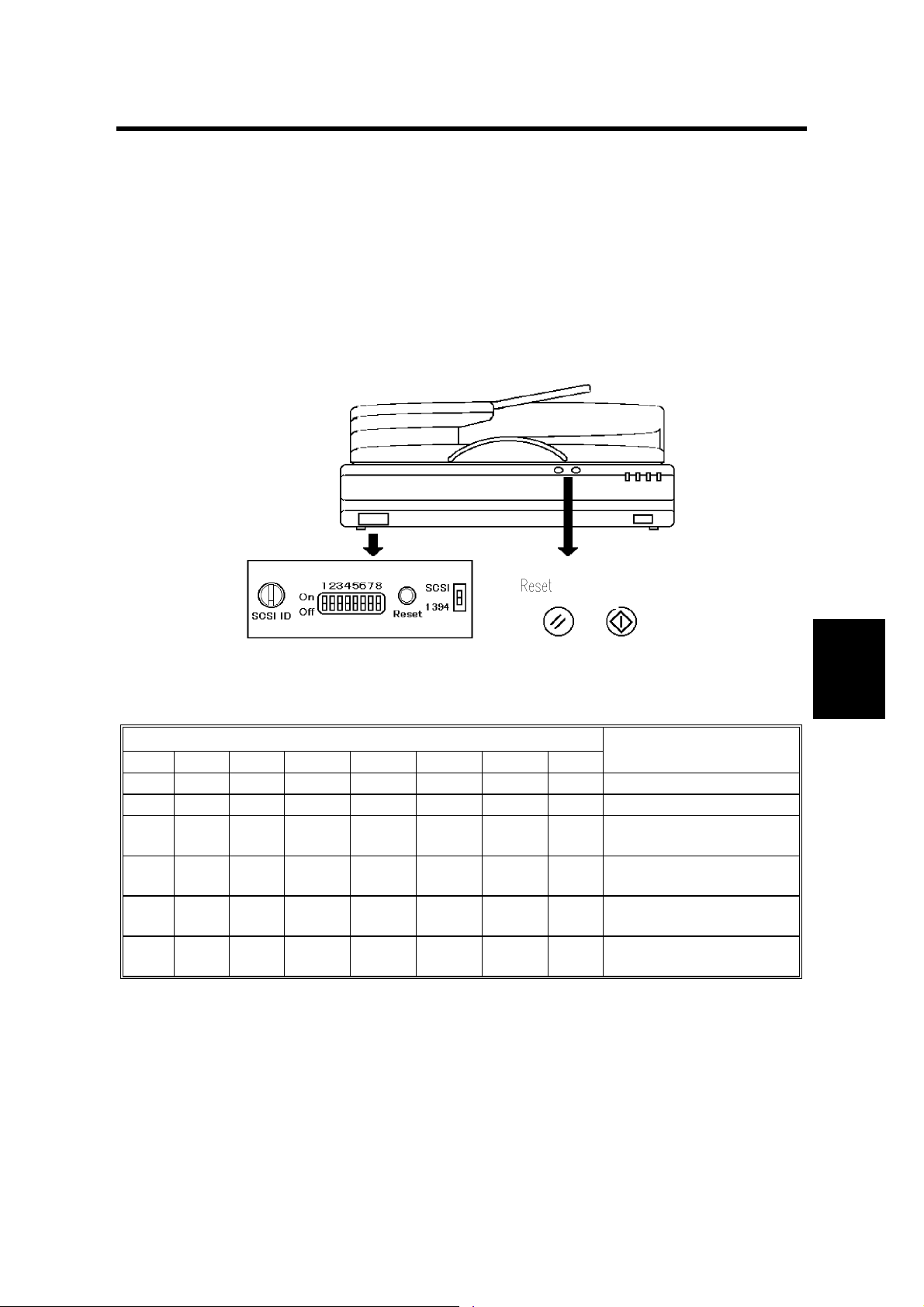
5.1.1 DIP SWITCH COMBINATIONS
After changing the DIP switch setting, either switch the power on and off, or press
the reset switch.
If you change the position of the SCSI ID rotary switch during these tests, be sure
to put it back to the original position once you have finished.
StartClear Modes
G412R501.TIF
DIP switch setting table (Normal mode)
DIP switch
SW1 SW2 SW3 SW4 SW5 SW6 SW7 SW8
0 - - - 0 0 0 0 SCAM function disabled
1 - - - 0 0 0 0 SCAM function enabled
-0- - 0 0 0 0
-1- - 0 0 0 0
--0 - 0 0 0 0
--1 - 0 0 0 0
SCSI synchronous
transfer enabled
SCSI synchronous
transfer disabled
Internal SCSI
termination on
Internal SCSI
termination off
Item
0: Off, 1: On, -: Don’t care
NOTE: When SCAM function is enabled, this machine is automatically given an
SCSI ID. This prevents you from daisy-chaining other peripherals with the
scanner. If you wish to attach multiple components, disable SCAM and set
the SCSI ID at the SCSI rotary switch (☛ Table A: Normal mode).
Tables
Service
5-1
Page 31

DIP SWITCH FUNCTION 28 December, 2000
DIP switch setting table (service level test mode)
DIP switch
SW1 SW2 SW3 SW4 SW5 SW6 SW7 SW8
--- - 1 0 0 0
--- - 0 1 0 0
--- - 0 0 1 0
--- - 1 0 1 0
--- - 0 1 1 0
--- - 1 1 1 0
--- - 0 0 0 1
--- - 1 0 0 1
--- - 0 1 0 1
--- - 0 0 1 1
--- - 1 0 1 1
--- - 0 1 1 1
--- - 1 1 1 1
5.1.2 NORMAL MODE
SCSI ID Rotary
switch number
0 SCSI ID 0
1 SCSI ID 1
2 SCSI ID 2
3 SCSI ID 3
4 SCSI ID 4
5 SCSI ID 5
6 SCSI ID 6
7 SCSI ID 7
8 Not used
9 Not used
Contents
Item
ADF counter
Sensor test mode
Flash ROM upload
Exposure lamp on-time
White balance
adjustment mode
Book size check mode
Demonstration mode
Book mode counter
Self-diagnosis mode
Component test mode
Aging mode (Factory
use only)
ADF size check mode
EEPROM clear mode
NOTE: Only enabled when the SCAM function is disabled.
5-2
Page 32

28 December, 2000 DIP SWITCH FUNCTION
5.1.3 ADF COUNTER, BOOK MODE COUNTER AND EXPOSURE LAMP ON-TIME
SCSI ID rotary switch
SCSI ID Rotary
switch number
0 Not used 5 Ten thousands
1 Units (ones) 6 Hundred thousands
2 Tens 7 Millions
3 Hundreds 8 Not used
4 Thousands 9 Not used
Contents
SCSI ID Rotary
switch number
Contents
LED values
Number
0 Off Off Off Off
1 Off Off Off On
2 Off Off On Off
3Off Off On On
4 Off On Off Off
5 Off On Off On
6 Off On On Off
7 Off On On On
8 On Off Off Off
9On Off Off On
Power on
(Green)
Machine busy
(Green)
Document in
place (Green)
Error (Red)
NOTE: You must check the counts one digit at a time. Use the rotary switch to
select the digit. The value is indicated by a combination of the four LEDs.
The four LEDs are read as a four-bit, binary number.
Tables
Service
Example:
When the rotary switch is set for 1, the LEDs display the units (from the SCSI ID
Rotary switch table).
If the LEDs display (On, Off, Off, On), Counter value equals nine (from the LED
values table).
Rotary switch is 1 (units) (On, Off, Off, On)= 9
2 (tens) (On, Off, Off, Off)= 8
3 (hundreds) (Off, On, On, On)= 7
4 (Thousands) (Off, Off, Off, Off)= 0
5 (Ten thousands) (Off, Off, Off, Off)= 0
6 (Hundred thousands)(Off, Off, Off, Off)= 0
7 (Millions) (Off, Off, Off, Off)= 0
>>>Total counter value = 789 sheets (or hours)
5-3
Page 33

DIP SWITCH FUNCTION 28 December, 2000
5.1.4 SENSOR TEST MODE
SCSI ID rotary
switch number
0 Home position sensor
1 Registration sensor
2 ADF position
3 Original setting
4 Feed cover
5 Original reverse
6 Original exit
7 Not used
8 Not used
9 Not used
Contents
NOTE: If the selected sensor is on, all LEDs turn on. If the selected sensor is off,
all LEDs turn off.
5-4
Page 34

28 December, 2000 DIP SWITCH FUNCTION
ode
5.1.5 FIRMWARE UPDATE PROCEDURE
This procedure is for updating the firmware of the machine.
!
CAUTION
Do not turn off the machine while downloading the firmware.
IC Card Slot for Network m
l
[C]
[A]
IC Card Slot for SCSI model
[B]
G412R502.WMF
Scanner
Prepare an IC card that contains the required firmware.
Turn off the machine and remove the cover. (!x1)
[A]: Insert the IC card into the IC card slot.
Turn on the machine while pressing the start key. The update starts automatically.
NOTE: If you have installed the network option, this step is slightly different.
Since the new operation panel covers the start key, turn on the
machine while pressing switch [B] instead.
The status is indicated on the LCD.
Tables
Service
When it finishes, turn of f the machine and remove the IC card, then turn it back on.
NIB
Prepare an IC card that contains the required firmware.
Turn off the main switch and remove the cover (!x1)
[C]: Insert the IC card IC into the IC card slot.
Turn on the machine.
Select “Install” key on the operation panel.
The status in displayed on the operation panel.
Turn off the main switch and remove the IC card.
5-5
Page 35

DIP SWITCH FUNCTION 28 December, 2000
5.1.6 FLASH-ROM UPLOAD MODE
G412R502.TIF
Prepare an IC card that contains the required firmware.
Turn off the machine and remove the cover. (!x1)
Insert the IC card into the IC card slot.
Set the DIP switch. (☛ 5.1.1 DIP Switch Setting Table (Service level test mode))
Turn on the machine. The update starts automatically.
Status indicated in the LCD.
Turn off the machine, and turn it back on.
5.1.7 WHITE BALANCE ADJUSTMENT MODE
NOTE: Only when EEPROM is replaced to new one, this procedure is required.
After this adjustment, gray balance adjustment is required. (See ScanProbe manual)
Lay 10 sheets of Type 6200 paper chart on the exposure glass.
Set the DIP switch.
Turn on the main switch.
White balance automatically adjusted.
NOTE: This adjustment also can be done using Scan-Probe.
5-6
Page 36

28 December, 2000 DIP SWITCH FUNCTION
5.1.8 BOOK SIZE CHECK MODE
When a paper is laid down on the exposure gla ss, the book size sensor is active.
All LEDS is blinking.
SCSI ID Rotary
switch number
0 Not used
1 Book size sensor 1 (Original width 1)
2 Book size sensor 2 (Original width 2)
3 Book size sensor 3 (Original width 3)
4 Book size sensor 4 (Original width 4)
5 Book size sensor 5 (Original lengt h 1)
6 Book size sensor 6 (Original lengt h 2)
7 Not used
8 Not used
9 Not used
Contents
5.1.9 DEMONSTRATION MODE
SCSI ID Rotary
switch number
0 Scan in book mode (A3, 210m m/s)
1 Scan in book mode (A3, 70mm/s)
2 Scan in book mode (A3, 11.67 m m/s)
3 Scan in ADF mode (210mm/s) NOTE1)
4 Scan ADF mode (70mm/s) NOTE1)
5 Scan mode (11.67/mm/s) NOTE1)
6 Scan in ADRF mode (210mm/s) NOTE1)
7 Scan in ADRF mode (70mm/s) NOTE1)
8 ADF free running NOTE2)
9 ADRF free running NOTE2)
Contents
Tables
Service
NOTE: 1) The scanner drives any documents in the ADF.
2) The scanner drives the ADF without any document.
3) While feeding the document, the LEDs indicate the machine status as
usual. But, if an error occurs (e.g. misfeed, jam, etc), the scanner stops,
and the LEDs display the error condition.
5-7
Page 37

DIP SWITCH FUNCTION 28 December, 2000
5.1.10 SELF DIAGNOSTIC MODE
By setting this DIP switch, you can perform the following tests (☛ 4.1.2 Selfdiagnostic).
5.1.11 COMPONENT TEST MODE
SCSI ID Rotary
switch number
0 All components off
1 Exposure lamp on/off
2 Pick-up solenoid on/off
3 DF feed clutch on/off
4 Junction gate solenoid on/ of f
5 Not used
6 Not used
7 Not used
8 Not used
9 Not used
Contents
NOTE: 1) When the start but ton is presse d, the selected component turns on and
off repeatedly.
2) If the selected sensor is off, all LEDs turn off. If the selected sensor on,
all LEDs turn on.
5.1.12 ADF SIZE CHECK MODE
SCSI ID Rotary
switch number
0 Not used
1 Original width sensor (Posit i on 1)
2 Original width sensor (Posit i on 2)
3 Original length sensor 1
4 Original length sensor 2
5 Not used
6 Not used
7 Not used
8 Not used
9 Not used
Contents
5-8
Page 38

28 December, 2000 DIP SWITCH FUNCTION
5.1.13 EEPROM CLE AR MODE
Push the start button, and hold it down for three seconds.
All the LEDs turn on.
When all the LEDs turn off, the EEPROM is cleared.
The following data is cleared:
a) ADF counter data
b) Book mode counter data
c) Exposure lamp on-time data
The following data is not cleared:
a) Destination data
b) Optimal tune data
c) Registering tune data
Tables
Service
5-9
Page 39

SERVICE PROGRAM MODE (WITH NIB OPTION) 28 December, 2000
5.2 SERVICE PROGRAM MODE (WITH NIB OPTION)
5.2.1 THE SP MODE DESCRIPTION
Entering the service mode
Push the " button.
Push the # button.
Push the $ button.
Push the % button.
Hold the & button down for three seconds.
Service
Class
1
mode
number
001 FTP port Sets the FTP port number
002 Version Displays the firmware version
003 Lot No. Displays the machine lot number
004 Error log Displays the service call number (SC)
005
006 Initialize all data Initialize all SP mode data
007 Initialize SCAN-NIC Data Data related to the network is initialized.
008 Density Setup1
009 Density Setup2
010 Density Setup3
011 Density Setup4
012 Density Setup5
013 Density Setup6
014 Density Setup7
015 Flash ROM disc format Format the flash ROM
016 Binary color
Initialize SCAN-data Initialize SP mode data (SPNo.006 is not
Description Function
removed)
Adjust Density1. [0-255/40/1]
Adjust Density2. [0-255/70/1]
Adjust Density3. [0-255/100/1]
Adjust Density4. [0-255/130/1]
Adjust Density5. [0-255/160/1]
Adjust Density6. [0-255/190/1]
Adjust Density7. [0-255/220/1]
Select binary color [Yes or No/No]
NOTE: The setting range is in brackets and the default setting is in bold.
Density setup sample:
Case 1: Density fluctuations are small.
Case 2: Increases document density.
Case 3: Reduces density.
Example:
Case
1 85 100 115 130 145 160 175
2 70 100 130 160 190 220 250
3 10 40 70 100 130 160 190
Density
setup 1
Density
setup 2
Density
setup 3
Density
setup 4
Density
setup5
Density
setup 6
Density
setup 7
NOTE: It is reference value. Adjust this value by the scanning image condition.
5-10
Page 40

28 December, 2000 NETWORK SETUP(WITH NIB OPTION)
5.3 NETWORK SETUP(WITH NIB OPTION)
5.3.1 NIB SETUP TABLE
Scanner function/Network table
Item No Setting name Function
1 Scanner IP address Setup IP address [011.022.033.044]
2 Subnet address Setup Subnet addr ess [ 000.000.000.000]
3 Gateway address Setup Gateway address [000.000.000.000]
4
5 Access mask Setup Access mask [000.000.000.000]
6
7
8 MAC address Non-enterable field
9 Ftp port number Setup Ftp port no. [ 03670]
10
Access control
address
Network boot
Delivery scanner
address
Transmission speed Select transmission speed
Setup Access control address [000.000.000.000]
Select Network boot [ None or ARP+PING or A RP+PING
/RARP+TFTP or RARP+TFTP/BOOTP or RARP+TFTP
or RARP+TFTP/ BO OTP or BOOTP or DHCP/None]
Setup Delivery scanner ad dress [000.000.000.000]
[auto or 10base or 100base/auto]
NOTE: The setting range is in brackets and the default Setting is in bold.
Scanner function/configuration table
Item No Setting name Function
2
Scanner/TWAIN
connection timeout
Indicate Scanner/TWAIN connection timeout [0-30]
5.3.2 NIB ERROR LOG DESCRIPTIONS
rapp
0104-0000 A compulsory reset occurrence.
0104-0001 By the CosScanOpen() function, error. (Indicate SC4005)
0104-0002 By the CosScanRead() function, error. (Indicate SC4005)
0104-0003 By the CosScanExec() function, error.
0104-0004 By the CosMShareAt() function, error.
0104-0005 By the CosMShareAt() function, error.
0104-0006 By the CosMShareAt() function, error.
0104-0007 By the CosMShareAt() function, error.
0104-0101 Connection idle for five minutes.
0104-0102 Resource release error
Tables
Service
5-11
Page 41

NETWORK SETUP(WITH NIB OPTION) 28 December, 2000
nas
0108-1xxx
0108-2002 File communication protocol is abnormal. (Indicate SC4004)
0108-3001
0108-3002 Cannot connect to the LINF. (no resp onse f r om the NIB) (Indicate SC4004)
0108-4001 No response TCP/IC at NIB
0108-4002 TCP/IC at NIB, error.
NIC initialization failure. xxx is a diagnost ic error co de fr om the NIC. (Indicate
SC4004)
Cannot connect to the LINF. (no response from the scanner) (Indicate
SC4004)
SC related to the network interface card
SC4001 Extended memory error.
SC4002 Flash ROM check-sum error
SC4003 No battery on NIB
SC4004 NIB error
SC4005 Application error
5-12
Page 42

28 December, 2000 O RIGINAL SIZE SENSOR COMBINATION TABLE
5.4 ORIGINAL SIZE SENSOR COMBINATION TABLE
[A]
L1-1 L1-2 L2-1 L2-2
W1
[C]
W2
No. US EU W
[B]
G412S500.WMF
1
W
[A]: Original Length Sensor 1
[B]: Original length Sensor 2
[C]: Original Width Sensor
2
L1-1 L1-2 L2-1 L2-2
1 A3 Lengthwise X O ON ON ON ON – –
2 B4 Lengthwise X O ON – ON ON – –
3 A4 Lengthwise X O – – ON ON – –
4 A4 Sideways X O ON ON – – – –
5 B5 Lengthwise X O – – ON – – –
6 B5 Sideways X O ON – – – – –
7 11” x 17” (DLT) O X ON ON ON ON ON ON
8 11” x 15” O*
1
X ONONONONONON
9 10” x 14” O X ON – ON ON ON ON
10 8.5” x 14” (LG) O X – – ON ON ON ON
11 8.5” x 13” (F4) X O – – ON O N ON –
12 8” x 13” (F) X O*
2
– – ON ON ON –
13 8.5” x 11” (LT) O X – – ON O N – –
14 8.5” x 11” (LT) O X ON ON – – – –
15 10” x 8” O X – – ON – – –
Tables
Service
*1: Detects as DLT *2: Detects as F4
5-13
Page 43

28 December, 2000 MACHINE O VERVI EW
6. DETAILED FUNCTION DESCRIPTIONS
6.1 MACHINE OVERVIEW
[A] [B] [C] [D] [E] [F] [G] [H] [I]
[A]: Scanner HP Sensor
[B]: DF Exposure Glass
[C]: 2nd Mirror
[D]: 2nd Scanner
[E]: Exposure Glass
[F]: Exposure Lamp
[G]: 1st Scanner
[H]: Lens
[I]: CCD
[J]: Original Length Sensor 2
[K]: Original Length Sensor 1
[L]: 1st Mirror
[M]: Scanner Motor
[N]: 3rd Mirror
[O]: Original Width Sensor
[J][K][L][M][N][O]
G412D500.WMF
Detailed
Descriptions
6-1
Page 44

CONTOROL SYSTEM BLOCK DIAGRAM 28 December, 2000
6.2 CONTOROL SYSTEM BLOCK DIAGRAM
ARDF
Original Length Sensor 1
Original Length Sensor 2
Original Width Sensor
Scanner Home Position
SBU
Exposer Lamp
Stabilizer
STM3
CN207CN209 CN202 CN204 CN208
CN205 CN206CN212
VIOB
CN203 CN204
CN3 CN4
CN2
CN1
PSU
CN5
CN204CN210
NIC Operation Panel
CN211
OIPU NIB
CN102
CN101
CN201
FAN
ADF Interlock Sensor
SOP
SWB
CN1038
CN103
SCU
CN105
IEEE1394
3000DC
Option
G412R504.WMF
The SCU controls this machine. Its CPU checks all sensors and manages the SCSI
I/F, NIB I/F, IEEE1394 I/F and VIOB. The SCU has EEPROM and DRAM. It also
contains the image processing ASIC, which processes images from the CCD.
The VIOB controls several sensors and control boards and ARDF.
6-2
Page 45

28 December, 2000 SCANNING
6.3 SCANNING
6.3.1 OVERVIEW
[A]
[C]
• The exposure lamp (a xenon lamp in this model) [A] illuminates the original. The
image is reflected onto a CCD (charge coupled device) [B] via the 1st, 2nd, and
3rd mirrors, and through the lenses [C].
• The scanner scans the white plate [A] on the underside of the ADF exposure
cover to perform the shading function.
• The scanners stop when the first scanner activates the home position sensor [E].
• If the scanner home position sensor is not activated within a certain time, a home
position sensor error will occur.
[B]
G412D500.WMF
6-3
Detailed
Descriptions
Page 46

SCANNING 28 December, 2000
6.3.2 SCANNER DRIVE MECHANISM
Scanner Motor
Scanner drive Relley
Scanner Drive Shaft
Scanner Wires
1st Scanner 2nd Scanner
G412D501.WMF
[F]
[B]
[C]
[E]
[D]
[A]
[G]
G412R017.WMF
6-4
Page 47

28 December, 2000 SCANNING
6.3.3 IMAGE PROCESSING
• The CCD generates three analog video signals.
• The SBU (Sensor Board Unit) converts these analog signals to 12-bit digital
signals.
• It sends these digital signals to the SCU (Scanner Control Unit) board through
the VIOB board.
• The RIPU (Image Processing Unit) IC on the SCU processes the image, and
then the image data is sent to the computer through the Memory Control IC and
the SCSI controller.
OIPUB IEEE1394
OIPUB
ISIC
SBU VIOB
E
R
R
G
G
CCD Shading
B
BO
O
E
O
E
Analog
Processor
Analog
Processor
Analog
Processor
A/D
Converter
A/D
Converter
A/D
Converter
12bit
12bit
12bit
DRAM
RIPU
Output
Selector
8 bit
8 bit
8 bit
VIDEO I/F
8 bit
Video
Selector
NIC
SIBC2
SCU
SCSI
NIB
G412R505.WMF
LAN
Detailed
Descriptions
6-5
Page 48

SCANNING 28 December, 2000
SBU and VIOB
The CCD converts the light reflected f rom the o rigin al into an analog signal.
The CCD has an odd and an even output line for each of the three colors. Each
color also has an analog processing IC. The analog processing IC performs the
following operations.
1. Z/C (Zero Clamp)
Adjusts the black level reference for even pixels to match the odd pixels.
2. Signal Amplification
Operational amplifiers in the AGC (Auto Gain Control) circuit amplify the analog
signal. The CPU on the SCU board controls the maximum gain.
After the above processes, the analog signals are converted to 12-bit digital signals
by the A/D converters. Each pixel is given a value from the 256-grade scale. The
shading function then corrects those signals. Shading correction prevents uneven
images caused by fluctuations in scanned data due to changes in light intensity
and CCD sensitivity.
RIPU on SCU
The RIPU is the image processor on the SCU. It handles the following:
1. Line skipping correction
2. Scan line correction
3. Black and white conversion
4. Gamma (γ) correction
5. Color resolution
6. Filtering
7. Magnification
8. Scale processing
9. Erasure of Irregular Dots
Line skipping correction
Ideally, this machine would scan at a constant speed. However, when the data
transfer speed slows down, the 1st scanner must also slow down to match. If the
1st scanner must stop to wait on the client or server, duplicate lines may be
scanned. These can create a visible seam between the scanned sections. Line
skipping correction erases duplicate image lines, ensuring a smooth final image.
6-6
Page 49

28 December, 2000 SCANNING
Scan line correction
The CCD consists of three lines of elements, one for each color (red, green and
blue). Since there is a slight gap between the lines, each line is scanning a slightly
different part of the image. To produce the final image, these three outputs need to
be synchronized. Since the deviation between the lines varies with the scanner
speed, a deviance value must be calculated in proportion to the speed.
Black and white conversion
When the machine scans a color original in the black and white mode, the RGB
information needs to be converted into a grayscale image. Black and white
conversion provides four different methods.
1. RGB data: All three colors are combined into the grayscale.
2. R data mode: Only the data from the red CCDs are used. This 256-grade data
is used directly as a 256-grade grayscale. Since green and blue data is not
collected, those colors appear black in the final image.
3. G data mode: As R data but only using green.
4. B data mode: As R data but only using blue.
Gamma (
) correction
γγγγ
There should be a linear relationship between the original image density and the
CCD output.
Gamma correction adjusts for deviations from this ideal. It includes both brightness
and contrast corrections.
Color resolution
Because of the differences in color space, the color observed by a person, and the
color value sensed by the CCD can vary. Color resolution corrects the color data
gathered by the CCD. It uses a color table that adjusts for the way particular colors
are displayed on specific CRTs. This allows a more-natural representation of the
scanned image.
Filtering
There are two software filters: the MTF (Modulation Transfer Function) filter and
the smoothing filter. The MTF filter emphasizes sharpness, and is used with
documents that contain both text and photo areas. The smoothing filter is only
used for photo-image documents.
Detailed
Descriptions
6-7
Page 50

SCANNING 28 December, 2000
Magnification
The RIPU enlarges or reduces the image data in the scan direction.
Reduction and enlargement in the sub scan direction are done by changing the
scanning speed, using LIFO (last in, first out).
Scale processing
This process generates image densities of up to 256 levels for each pixel. It uses
simple binary, dithering, and error diffusion processing.
Simple binary processing sets the level based on a threshold value. There are no
shades of gray. The output is black or white only.
Dither processing is used to reproduce originals with continuous tones, such as
photographs on machines that cannot output true grayscales. It produces different
shades of gray by creating patterns of black and white dots. There are no gray
dots.
The error diffusion process reduces the difference in contrast between light and
dark areas of a halftone im age. Each pixel is corrected using the difference
between it and the surrounding pixels. The corrected pixels are then compared with
a matrix table. Error diffusion is often used in text/photo mode. It is a good
compromise because it reduces the contrast between light and dark areas of
halftone images, while having no effect on letter areas.
Erasure of Irregular Dots
When the CCD output is converted to a simple b i nary image, slight variations
(noise) may result in individual pixels being incorrectly classified as either black or
white. This process compares each pixel with its neighbors, using a matching
technique to identify and remove these irregular dots.
OIPUB
The OIPUB is an optional image-processing unit. It improves the processing of
black and white images using the following features:
1. Auto binary processing
2. Auto Image area separation
3. Manual Image area separation
Auto binary processing
When making simple binary scans of a light original (e.g. gray text on a white
background), the threshold level is adjusted. This allows the lighter shades to
appear in the final image (in the above example, as black text on a white
background).
6-8
Page 51

28 December, 2000 NEWORK INTERFACE
Auto image area separation
When a sca nned document contains both text and photo areas, the machine
searches for the outlines of the text. Based on these outlines, it separates the
image into text and photo areas. Text areas use simple binary processing. Photo
areas use dithering and error diffusion.
Manual image area separation
Here, the user separates the text and photo areas by hand (Use the TWAIN
software). Image processing is the same as in auto image area separation.
6.4 NEWORK INTERFACE
The following network scanning options are available:
1. Network Transmission scanning
This scanner transmits the scanning image data to the scanner server. The
scanner server then transmits the data to a client PC.
2. Network TWAIN scanning
The client PC sends scanning commands directly to the scanner. The scanner then
sends the scanning image data back to the client PC.
Detailed
Descriptions
6-9
Page 52

IEEE1394 INTERFACE 28 December, 2000
6.5 IEEE1394 INTERFACE
6.5.1 IEEE1394
IEEE1394, also known as FireWire (a name patented by Apple), is an easy-to-use
peer-to-peer networking technology, allowing speeds of up to 400 Mbps.
The current standard contains the following features, which are supported in most
devices:
• Hot swapping (cables can be connected and disconnected while the
computer and other devices are switched on)
• Peer-to-peer networking (no hub required)
• No terminator or device ID is required, unlike SCSI
• Automatic configuration of devices upon start-up (plug and play).
• Real-time data transfer at 100, 200, and 400 Mbps
• Common connectors for different devices
1394 I/F
1394 I/F
G056D513.WMF
The cable length is limited to 4.5 m (15ft). However, up to 16 cables and 63
devices can be connected to an IEEE1394 network.
IEEE1394 cables can be either 4-pin (data only) or 6-pin (data and power).
However, this machine only uses the 6-pin connectors. The machine has two 6-pin
ports.
6-10
Page 53

28 December, 2000 IEEE1394 INTERFACE
6.5.2 BLOCK DIAGRAM
IEEE1394 Board
EEPROM
1394 I/F
IBM Compatible
1394 I/F
PHY
TSB 412V02
• PHY: Physical layer control device
• LINK: Link layer control device
• EEPROM: 256-byte ROM
LINK
TSV43LV81
SCU
Option I/F
G412R503.WMF
6-11
Detailed
Descriptions
Page 54

AUTO REVERSE DOCUMENT FEEDER
Page 55

28 December, 2000 SPECIAL TOOLS
1. REPLACMENT
!
CAUTION
Turn off the main power switch and unplug the machine before attempting
any of the procedures in this section.
This manual uses the following .
☛: See or Refer to !: Screw ": Connector #: Snap ring $:E-ring
1.1 SPECIAL TOOLS
Part number Description Description section Q ty
G0049668 Silicone grease (KS-660) ☛1.2.7 ORIGINAL LENGTH, WIDTH
SENSOR BOARD
1
1.2 REPLACEMENT
1.2.1 LEFT COVER
[B]
[A]
A859R110.WMF
Front and rear covers. (☛ 1.2.1 DF EXIT TABLE AND COVERS)
[A]: Lower left stay unit (!x2).
[B]: Left cover.
Peripherals
1-1
Page 56

REPLACEMENT 28 December, 2000
1.2.2 P APER FEED UNIT
[B]
[A]
A859R102.WMF
[A]: Open the left cover
[B]: Detach the paper feed unit by sliding it toward the front of the machine
(spring-loaded side) and then lifting the far side.
1.2.3 SEPARATION ROLLER
[A]
[C]
[A]: Open Left cover
[B]: Lift the original feed guide
[C]: Separation roller cover
[D]: Separation roller
[B]
A859R105.WMF
1-2
Page 57

28 December, 2000 REPLACEMENT
1.2.4 PICK-UP ROLLER
[B]
[A]
A859R103.WMF
[A]: Original feed unit
[B]: Pick-up roller (# x1)
1.2.5 FEED BELT
[B]
[A]
A858R204.WMF
[C]
Peripherals
[D]
Open the left cover
[A]: Paper feed unit (☛ 1.2.2 PAPER FEED UNIT)
[B]: Open the paper feed guide
[C]: Belt holders
[D]: Feed belt
1-3
A858R205.WMF
Page 58

REPLACEMENT 28 December, 2000
1.2.6 ORIGINAL SET/ORIGINAL REVERSE SENSOR
[A]
[C]
[B]
A858R201.WMF
Open the left cover
[A]: Open the original feed guide plate while pushing the left and right pawls
[B]: Original set sensor ("x1)
[C]: Original reverse sensor ("x1)
1-4
Page 59

28 December, 2000 REPLACEMENT
1.2.7 ORIGINAL LENGTH, WIDTH SENSOR BOARD
[A]
[B]
[C] [D]
A859R107.WMF
A859R108A.WMF
[A]: Open the original table
[B]: Upper part of the table (!x3).
[C]: Width sensor board (!x3, "x1)
[D]: Length sensors ("x1)
A859R113.WMF
NOTE: To ensure proper detection of paper size, after wiping the sensor board and
terminal plate with a dry cloth (or cloth with alcohol), apply silicone grease
(KS-660) to the terminal plate.( ☛1.1 SPECIAL TOOLS)
Peripherals
1-5
Page 60

REPLACEMENT 28 December, 2000
1.2.8 DF EXIT TABLE AND COVERS
[A]
[C]
[A]: Open the feed cover
[B]: Open the reverse table
[C]: Front cover (!x2)
[D]: Rear cover (!x2)
[E]: DF exit table (!x3)
1.2.9 FEED COVER SENSOR
[D]
[B]
[E]
A859R101.WMF
[A]
Rear cover. (☛ 1.2.1 DF EXIT TABLE AND COVERS)
[A]: Feed cover sensor
G412R511.WMF
1-6
Page 61

28 December, 2000 REPLACEMENT
1.2.10 REGISTRATION SENSOR
[B]
[A]
A859R111.WMF
Front and rear covers. (☛ 1.2.1 DF EXIT TABLE AND COVERS)
[A]: Transport guide plate.
[B]: Registration sensor. ("x2).
1-7
Peripherals
Page 62

CLUTCH/SOLENOID/MOTORS 28 December, 2000
1.3 CLUTCH/SOLENOID/MOTORS
[B]
[C]
[F]
[D]
[E]
Rear cover. (☛: 1.2.1 DF EXIT TABLE AND COVERS)
Then follow the instructions below for each part:
DF Feed Clutch
[A]: Clutch ($x1, "x1).
Pick-up Solenoid
[B]: Pick-up solenoid (!x3, #x1, "x1).
Junction gate solenoid
DF exit table (☛1.2.8 DF EXIT TABLE AND COVERS)
[C]: Junction gate solenoid (!x2, #x1, "x1)
Transport Motor
Remove the pick-up solenoid (!x3, #x1, "x1).
[D]: Bracket (!x2).
[E]: Transport motor (!x2, "x1).
[A]
A858R202.WMF
DF Feed Motor
Remove the pick-up solenoid (!x3, #x1, "x1).
Bracket [D](!x2).
[F]: DF feed motor (!x2, "x1).
1-8
Page 63

28 December, 2000 MACHINE O VERVI EW
2. DETAILED FUNCTION DESCRIPTION
2.1 MACHINE OVERVIEW
2.1.1 M ECHANICAL COMPONENT LAYOUT
Mechanical component layout
[B] [C] [D]
[A]
[Q]
[P]
[O]
[A]: Separation Roller
[B]: Paper Feed Belt
[C]: Pick-up Roller
[D]: Original Set Sensor
[E]: Original Width Sensor Board
[F]: Original Length Sensor 1
[G]: Original Length Sensor 2
[H]: Original Table
[I]: Reverse Table
[E]
[G]
[J]: Reverse Roller
[K]: Junction Gate
[L]: Exit Roller
[M]: Original Exit Sensor
[N]: 2nd Transport Roller
[O]: Original Exposure Guide
[P]: Registration Sensor
[Q]: 1st Transport Roller
[F]
[J][K][L][M][N]
[H]
[I]
A858D201.WMF
2-1
Peripherals
Page 64

MACHINE OVERVIEW 28 December, 2000
Drive layout
[C] [D]
[B]
[E]
[F]
[A]
[J]
[I]
[H]
[A]: Separation Roller
[B]: Original Feed Belt
[C]: Pick-up Roller
[D]: DF Feed Clutch
[E]: DF Transport Motor
[G]
A858D203.WMF
[F]: DF Feed Motor
[G]: Reverse Table Roller
[H]: 2nd Transport Roller
[I]: Exit Roller
[J]: 1st Transport Roller
2-2
Page 65

28 December, 2000 MACHINE O VERVI EW
2.1.2 CONTROL SYSTEM
• The CPU on the scanner SCU controls the transport motor, DF feed motor, DF
feed clutch, junction gate solenoid and pick-up solenoid.
• The CPU on the scanner SCU also monitors all DF sensors
• The DF–VIO
• The VIOB connection is checked automatically just after power is supplied to the
SCU.
CN105 CN104 CN102
DF Clutch
CL
STM1
DF Feed Motor
DF Pick-up
Solenoid
Junction Gate Solenoid
Registration ADF Position Sensor
Original Set Sensor
Feed Cover Sensor
Original Exit Sensor
Original Reverse Sensor
SOL2
Registration
SOL1
CN107 CN108 CN104
CN103CN106
ARDF
CN100
CN101
VIOB
STM2
DF Transport Motor
Original Width Sensor Board
Original Length Sensor 1
Original Length Sensor 2
SCU
G412R510.WMF
2-3
Peripherals
Page 66

DETAILED FUNCTION 28 December, 2000
2.2 DETAILED FUNCTION
2.2.1 ORIGINAL SIZE DETECTION
[A]
[B]
[C]
A859D104.WMF
• The original size detection mechanism consists of the original width sensor board
[A] and two original length sensors--sensor-1 [B] and -2 [C].
• Based on the combined output of the length sensors and the width sensor board,
the machine can calculate the size of the original.
NOTE: Since the width sensor’s terminal plate is attached to the original guide, all
the originals must be the same width.
2-4
Page 67

28 December, 2000 SERVI CE TABLE
2.3 SERVICE TABLE
2.3.1 ORIGINAL SIZE SENSOR AND BOARD COMBINATION
Original Sensor Board
A3 (297 x 420)
B4 (257 x 364)
A4 (Lengthwise)
(210 x 297)
A4 (297 x 210)
(Sideways)
B5 (182 x 257)
(Lengthwise)
B5 (257 x 182)
(Sideways)
A5 (148 x 210)
(Lengthwise)
A5 (210 x 148)
(Sideways)
11" x 17" (DLT)
11" x 15"
10" x 14"
8.5" x 14" (LG)
8.5" x 13" (F4)
8" x 13" (F)
8.5" x 11"
(Lengthwise)
8.5" x 11"
(Sideways)
10" x 8"
(Lengthwise)
5.5" x 8.5"
(Lengthwise)
(HLT)
5.5" x 8.5"
(Sideways) (HLT)
NA EU
✗❍
✗❍
✗❍
✗❍
✗❍
✗❍
✗✗
✗❍
❍✗
❍✗
❍✗
❍✗
✗❍
❍❍
❍✗
❍✗
❍✗
❍✗
❍✗
Combination Output
P4 P3 P2 P1
ON — — — L L ON ON
—ON— — L H ON ON
——ON—
ON — — —
———ON
—ON— —
———ON
——ON—
ON — — — L L ON ON
ON — — — L L ON ON
—ON— — L H ON —
——ON— H L ON —
——ON— H L ON —
——ON— H L ON —
——ON—
ON — — —
—ON— —
———ON
——ON—
Original
Width-1
HL
LL
HH
LH
HH
HL
HL
LL
LH
HH
HL
Original
Width-2
Original
Length-1
ON —
——
ON —
——
——
——
ON —
——
ON —
——
——
Original
Length-2
Key
✗
: No, ❍: Yes
ON: Paper present NA: North America, EU: Europe
2-5
Peripherals
Page 68

SERVICE TABLE 28 December, 2000
NOTE: 1) P1-P4 represents the four positions on the width sensor board. ON
indicates the presence of the terminal plate in a given position. “Original
Width-1” and “Original Width-2” are the outputs from the sensor board to
the ARDF Interface board. The state of these outputs (L or H) depends
on the position of the terminal plate on the sensor board (P1, P2, P3, or
P4). For example, if the terminal plate is at P4, both outputs are L.
2) A reading of “L” on either of the width sensor outputs indicates that the
terminal plate is connecting the GND pattern with the width sensor
output signal line.
Original Width Sensor Board Combination
GND Pattern
Original Width 1
Original Width 2
Original Side
Guide Position
P1P2P3P4
A3/A4S B4/B5S A4L/A5S B5L/A5L
A858D501.WMF
2-6
Page 69

28 December, 2000 SERVI CE TABLE
2.3.2 PICK-UP AND SEPARATION
[A]
[E]
[D]
[C]
[B]
A859D105.WMF
[E]
[F]
[G]
A858D505.WMF
• The originals pushes actuator [A] and the original set sensor [B] is activated.
• After pressing the start button, the pick-up solenoid [C] is activated and the lift
plate [D] lifts the originals until they comes in contact with the pick-up roller [E].
• The mechanism is an FRR system, consisting of the original feed belt [F] and
separation roller [G].
Peripherals
2-7
Page 70

SERVICE TABLE 28 December, 2000
2.3.3 ORIGINAL TRANSPORT AND EXIT
Single –sided originals
[E]
[F]
[A]
[B]
A859D107.WMF
[C] [D]
• The DF feed motor feeds the separated original to the first transport roller [A] at
maximum speed.
• When the registration sensor [B] detec ts the leading edge , the motor stops
briefly.
• Then the feed and transport motors turn on agai n, and fee d the or i g i nal throug h
scanning area at a lowe r speed.
• The original is fed out by the second transport roller [E] and the exit roller [F].
2-8
Page 71

28 December, 2000 SERVI CE TABLE
Double-side originals
– Front side –
When the registration sensor [A] detects
the leading edge of the original, the DF
feed motor and the transport motor both
switch off. After a brief interval, the
transport motor alone reactivates to drive
the first and the second transport roller [B,
C] and the exit roller [F].
– Rear Side –
When the original exit sens or [D] detects
the leading edge of the original, the
junction gate solenoid is activated and the
junction gate [E] opens. To transport the
original towards the reverse table [F].
After the trailing edge of the original
passes the exit sensor [D], the junction
gate solenoid switches off and the junction
gate [E] closes.
[B]
[A]
[B]
[C]
[F]
[D]
[F]
[E]
[E]
[G]
A858D204.WMF
[G]
A858D205.WMF
When the original has been fed completely onto the reverse table, the DF feed
motor switches on in reverse. The reverse roller [G], exit roller [F] and first transport
roller [A] then feed the original back to the scanning area.
The original is then sent to the reverse table [H] a second time. This ensures that
the duplex copies will be properly stacked front side down in the exit tray [I].
[H]
A858D206.WMF
[I]
A858D207.WMF
Peripherals
2-9
Page 72

SERVICE TABLE 28 December, 2000
2.3.4 TIMMING CHARTS
Single-sided mode (not pre-feed, not thin paper)
DF Feed Motor
DF Transport Motor
DF Clutch
DF Pick-up Solenoid
Original Set Sensor
Registration Sensor
Original Exit Sensor
CW: clockwise
CCW: counter clockwise
CW
OFF
CCW
ON
OFF
ON
OFF
ON
OFF
ON
OFF
ON
OFF
Paper Feed
35.6 mm
Feed and Scan
5 mm 56.5 mm 35.6 mm 5 mm 56.5 mm
Misfeed
Jam 2
Jam 3
Jam 4
Paper Feed Feed and Scan
ShadingShading
Misfeed
Jam 2
Jam 3
Jam 4
G412R506.WMF
2-10
Page 73

28 December, 2000 SERVI CE TABLE
Single-sided mode (pre-feed, not thin paper)
DF Feed Motor
DF Transport Motor
DF Clutch
DF Pick-up Solenoid
Original Set Sensor
Registration Sensor
Original Exit Sensor
CW: clockwise
CCW: counter clockwise
CW
OFF
CCW
ON
OFF
ON
OFF
ON
OFF
ON
OFF
ON
OFF
Paper Feed Feed and Scan 1
Shading
35.6 mm
5 mm 5 mm
Misfeed
Jam 2
Jam 3
Jam 4
Feed and Scan 2
Misfeed
Jam 2
Jam 3
Jam 4
5 mm
Feed and Scan 3
56.5 mm
Jam 2
Jam 3
Jam 4
G412R507.WMF
Peripherals
2-11
Page 74

SERVICE TABLE 28 December, 2000
Single-sided mode (pre-feed, thin paper)
DF Feed Motor
DF Transport Motor
DF Clutch
DF Pick-up Solenoid
Original Set Sensor
Registration Sensor
Original Exit Sensor
CW: clockwise
CCW: counter clockwise
CW
OFF
CCW
ON
OFF
ON
OFF
ON
OFF
ON
OFF
ON
OFF
Paper Feed Feed and Scan 1
Shading
35.6 mm
5 mm 5 mm
Misfeed
Jam 2
Jam 3
Feed and Scan 2
35.6 mm 35.6 mm
Misfeed
Jam 2
Jam 4
Jam 3
Jam 4
5 mm
Feed and Scan 3
56.5 mm
Jam 2
Jam 3
Jam 4
G412R508.WMF
2-12
Page 75

28 December, 2000 SERVI CE TABLE
Double-sided mode (not pre-feed)
DF Feed Motor
DF Transport Motor
DF Clutch
DF Pick-up Solenoid
Reverce Solenoid
Original Set Sensor
Registration Sensor
Original Exit Sensor
CW: clockwise
CCW: counter clockwise
CW
OFF
CCW
CW
OFF
CCW
OFF
OFF
OFF
ON
OFF
OFF
OFF
ON
ON
ON
ON
ON
Paper Feed Front Face Tray
Shading
35.6 mm
5 mm
Misfeed
Jam 2
Jam 3
Jam 4
Reverce Tray Reverce Face
Skew Correction
50.7 mm
32.8 mm
200 mm
Jam 1
Jam 2
Jam 3
Jam 4
50.7 mm
200 mm
Reverce Tray
Jam 1
Paper Feed (front face)
56.5 mm
Jam 2
Jam 3
Jam 4
G412R509.WMF
2-13
Peripherals
Page 76

SERVICE TABLE 28 December, 2000
Jam Conditions
JAM1: If the registration sensor does not turn on within the time required to feed
581.2mm after the original feed starts.
JAM2: If the registration sensor does not turn off within the time required to feed
the maximum original length (2060mm) after the original feed starts.
JAM3: If the original exit sensor does not turn on within the time required to feed
121.6mm after the registration sensor turns on.
JAM4: If the original exit sensor does not turn off within the time required for the
original length to feed after the original exit sensor turns on.
JAM5: The current original is stopped after the registration sensor detects its
leading edge, but the previous original is still in the scanning position.
JAM6: If the registration sensor turns off within the time required to feed 66mm
after the registration sensor turns on. The operator may then remove the
original from the ADF.
JAM7: If the ADF cover is opened while the ADF is in operation.
JAM8: If the ADF is lifted while in operation.
2-14
Page 77

SERVICE TOOL
SCAN-PROBE
Page 78

28 December, 2000 OPERATIVE CONDITIONS
1. OVERALL INFORMATION
1.1 OPERATIVE CONDITIONS
This service tool works under the following conditions.
PC Windows PC
CPU Pentium
Memory 64 MB or more
HDD Min 10 MB (Recommended: 210 MB or more)
OS Windows 95, 98, NT4.0 SP3 or lat er, 2000
Module Adaptec APSI driver Ver.4.57 (1008) or later
SCSI board Adaptec SCSI board (ISA, PCI, PCMCIA connection)
1.2 INITIAL SETTINGS
1.2.1 SCSI ID
The default SCSI ID of the scanner is 4. Therefore, this service tool is connected to
ID 4. If the SCSI ID is changed, you need to change the ID for this service tool.
1. Select “Scan”, “SCSI Configuration”
SRV003.BMP
2. Click “Select SCSI ID”.
Scan-
Probe
SRV004.BMP
1
Page 79

INITIAL SETTINGS 28 December, 2000
3. Input the SCSI ID.
SRV005.BMP
1.2.2 HOST ADAPTER ID
The host adapter ID of the SCSI interface Board and this service tool should be the
same.
The host adapter ID can be checked and changed with this service tool.
1. Scan -> Host Adapter
SRV006.BMP
2
Page 80

28 December, 2000 CHART SETTING POSITION
1.3 CHART SETTING POSITION
1.3.1 RICOH GRAY SCALE
*
*
Place the chart as shown.
1.3.2 RS-13
*
SC8.WMF
*
Scan-
Probe
Place the chart as shown.
SC9.WMF
3
Page 81

SIMPLE SCANNING 28 December, 2000
2. SCAN
An original can be scanned with this service tool to check the image quality.
2.1 SIMPLE SCANNING
2.1.1 OVERVIEW
This allows you to scan a document by inputting only a few simple settings.
SRV020.BMP
The basic menu for simple scanning is shown below.
SRV021.BMP
4
Page 82

28 December, 2000 SIMPLE SCANNING
2.1.2 SCANNING
Scanning is done in book mode by selecting the original size, mode (B/W,
grayscale, or color), and resolution.
1. Select “Scan”, “Simple Scanning”.
2. Enter document size.
3. Enter binary mode.
4. Enter resolution.
5. Click “Scan”.
SRV021.BMP
Scan-
Probe
5
Page 83

SIMPLE SCANNING 28 December, 2000
When scann i ng a document using ADF/ARDF.
1. Click “Detail”.
2. Select “ADF” or ”ARDF”.
3. Click “OK”.
SRV022.BMP
6
Page 84

28 December, 2000 SIMPLE SCANNING
2.1.3 SCANNING A SELECTED AREA
This mode is used when scanning a the selected area on the document.
The entire scanned image is displayed in the preview area on the right of the
screen using gray (256 graduations) mode and 100 dpi.
1. Select “Scan”, “Simple Scanning”.
2. Click “Preview”.
3. Select the area to scan (use the mouse).
4. Select the mode and resolution.
5. Click “Scan”
NOTE: To scan the whole original, select “Scan Document Size”.
7
SRV023.BMP
Scan-
Probe
Page 85

SCANNING BY MANUAL SETTING 28 December, 2000
2.2 SCANNING BY MANUAL SETTING
The original can be scanned by sending each SCSI command one by one.
NOTE: Do not use SCSI commands, if you do not get the hang of the SCSI
commands.
1. Select “SCSI configuration”.
2. Select the SCSI ID.
SRV003.BMP
SRV004.BMP
8
Page 86

28 December, 2000 CONTINUOUS SCANNING
2.3 CONTINUOUS SCANNING
Continuous scanning can be done in book or ADF mode.
SRV024.BMP
SRV025.BMP
1. Select “Continuous Reading”.
2. Set each item.
3. Click “Execute”.
4. Click “Stop”. (When you click “Stop”, scanning stops after completing the
current scan.)
The scanning conditions (such as scanning area/resolution) are the same as were
used for the previous scan that used “SCSI Configuration” or “Simple Scanning”
mode. This means that the document should be scanned using one of these
modes.
The functions of “File Save” and “Image Display” are shown below.
Image Display
Yes
Only the last image is displayed.
File Save
Yes
File Save
No
*1: This is the temp folder that is appointed by Windows.
Windows 9x : C:\Windows\Temp
Windows NT : C\Documents and Settings\(user name)\Local Settings\Temp
Saves the scanned image
automatically as a bitmap file
(IMG??.tmp) in the Temp folder. *
Only the last image is displayed.
The scanned image is not sav ed.
The displayed image can be s aved.
The scanned image is not d isp layed.
Saves the scanned image automatically
as a bitmap file (IMG??.tmp) in the
1
Temp folder.
The scanned image is not d isp layed.
The scanned image is not sav ed.
Image Display
No
Scan-
Probe
9
Page 87

OVERVIEW 28 December, 2000
3. SCANNING ADJUSTMENT
3.1 OVERVIEW
The scan counter can be checked, and adjustments and settings can be made in
this menu.
SRV007.BMP
3.2 SCAN COUNTER
Displays the scan counters and the exposure lamp operation time.
SRV009.BMP
1. Select “Scan”, “Scanning adjustment”.
2. Click “Scan Counter”.
3. Check value.
SRV008.BMP
10
Page 88

28 December, 2000 REGISTRATION
3.3 REGISTRATION
Use this to adjust the main scan and sub scan registration for ADF mode and book
mode.
The screen shows the adjustment values. They reset to “0” after being sent to the
scanner. Set moving distance.
1. Select “Scan”, “Scanning adjustment”.
2. Click “Registration adjustment”.
3. Enter th e value of registration.
4. Click “Transmit”.
5. Evaluate the registration. (☛4.2 REGISTRATION)
Origine
Outside (-)
Inside (+)
SRV010.BMP
Outside (-)
Inside (+)
Available area
Scan-
Probe
11
Main scan direction
SC1.WMF
Page 89

WHITE AND GRAY BALANCE 28 December, 2000
3.4 WHITE AND GRAY BALANCE
CAUTION: This adjustment is required after replacing the EEPROM.
3.4.1 WHITE BALANCE
Manual adjustment
Use this when returning the adjustment values to the factory settings.
1. Select “Scan”, “Scanning adjustment”.
2. Enter the value of each color.
3. Click “OK”.
4. Turn the main switch off and on.
5. Do the gray balance adjustment.
SRV011.BMP
12
Page 90

28 December, 2000 WHITE AND GRAY BALANCE
Automatic adjustment
1. Place 10 sheets of Type 6200 paper on the exposure glass.
2. Select “Scan”, “Scanning adjustment”.
3. Click the upper “Automatic adjustment” button (white balance).
SRV015.BMP
4. Click “OK”.
5. This adjustment takes approximately 20 seconds.
6. Click “OK”.
7. Turn the main switch off and on.
8. Do the gray balance adjustment.
SRV014.BMP
Scan-
Probe
13
Page 91

WHITE AND GRAY BALANCE 28 December, 2000
3.4.2 GRAY BALANCE ADJUSTMENT
CAUTION: 1) This adjustment is required after adjusting the white balance.
2) Before starting this adjustment, the registration for book mode
should be adjusted.
SRV011.BMP
1. Place the “Ricoh Gray Scale 1999.11.20” chart on the exposure glass.
2. Select “Scan”, “Scanning adjustment”.
3. Click the lower “Automatic adjustment” button (grey balance).
4. Click “OK”. Adjustment starts automatically.
SRV015.BMP
5. Click “OK”.
14
Page 92

28 December, 2000 WHITE AND GRAY BALANCE
SRV016.BMP
6. Click “OK”.
7. Check the image on the screen.
NOTE: If any of the following items are not “OK” replace the chart correctly and/or
clean the exposure glass and re-adjust the gray balance.
• “2” should be visible.
SRV017.BMP
• The blue square should be in the same gray area as shown below.
SRV018.BMP
• The inside of the blue square should have a constant density.
15
Scan-
Probe
Page 93

DESTINATION 28 December, 2000
3.5 DESTINATION
This checks and adjusts the version.
This setting is used for original size detection and default language when a NIB is
installed.
SRV019.BMP
1. Select “Scan”, “Scanning adjustment”.
2. Click “Select destination”.
3. Select a destination.
4. Click “OK”.
16
Page 94

28 December, 2000 OVERVIEW
4. IMAGE EVALUATION
4.1 OVERVIEW
This evaluation uses the scanned image (bitmap file) of an RS-13 test chart.
However, the following types of file cannot be evaluated, even if they are images of
an RS-13 test chart.
• Files not scanned with this service tool.
• Files modified with other applications.
SRV026.BMP
Scan-
Probe
17
Page 95

REGISTRATION 28 December, 2000
4.2 REGISTRATION
4.2.1 PROCEDURE
1. Place the RS-13 test chart on the exposure glass.
2. Scan this chart. (☛ 2.1 SIMPLE SCANNING)
3. Select the menu “Edit”.
4. Select menu “Select all”.
5. Select the menu “Evaluate”.
6. Select the menu “Registration”.
7. Enter 290.65 in the MxR, when scanning is ADF mode.
8. Click “Evaluate”.
9. Check Evaluation result and the specified value.
a) Registration of main scan direction
b) Registration of sub direction
10. Adjust registration as necessary. (☛ 3.3 REGISTRATION).
11. Execute this procedure, when registration adjusted.
SRV027.BMP
18
Page 96

28 December, 2000 REGISTRATION
4.2.2 SPECIFIED VALUE
Book mode
Main scan: 1 ± 1mm
Sub scan: 1 ± 1mm
ADF mode(front side)
Main scan: 0 ± 3mm
Sub scan: 0 ± 2mm
ADF mode(reverse side)
Main scan: = 0 ± 4mm
Sub scan: 0 ± 2mm
4.2.3 CONDITION
The registration can be checked using the following settings.
Original Size: A3
Mode: Gray (binary), Gray (16 graduations), Gray (256 graduations), Color (16M
colors)
Resolution: 600 dpi or more
NOTE: When using the ADF, change the MxR va lue to 290.65 before starting the
evaluation to prevent skew errors.
4.2.4 METHOD
Main scan
Dm = Lx – Lxc (mm)
Dm : Deviance of main scan
direction
My
Lxc
Lx Dm
Available area
0
Ly
LyDs
1
Ly
Lx : Basis distance of the
main scan
Lxc : Actual distance of main
scan
Sub scan
Ds = Ly – Lyc (mm)
MxL
MxR
Main scan
direction
SC2.WMF
Ds : Deviance of sub scan
direction
Scan-
Probe
Ly : Basis distance of the sub scan
Lyc : Actual distance of sub scan (Average of Ly0 and Ly1)
19
Page 97

SKEW 28 December, 2000
4.3 SKEW
4.3.1 PROCEDURE
1. Place the RS-13 test chart on the exposure glass.
2. Scan this chart. (☛ 2.1 SIMPLE SCANNING)
3. Select the menu “Edit”.
4. Select the menu “Select all”.
5. Select the menu “Evaluate”.
6. Select the menu “Skew”.
7. Check Evaluation result and the specified value.
a) Skew of main scan direction
b) Skew of sub scan direction
4.3.2 SPECIFIED VALUE
Book mode
Main scan direction : ±1%
Sub scan direction : ±1%
ADF mode
Paper size
A3 (Lengthwise) ±1.5% ±1.75%
A4 (Lengthwise) ±1.75% ±2%
A4 (Sideways) ±2% ±2%
A5 ((Lengthwise) ±2% ±2.5%
A5 (Sideways) ±2.5% ±3%
45 to 110kg 35 kg
NOTE: The main scan direction value and the sub scan direction are same value.
Paper thickness
20
Page 98

28 December, 2000 SKEW
4.3.3 CONDITION
Skew can be checked using the following settings.
Original Size: Not sp ecified
Mode: Gray (binary), Gray (16 graduations), Gray (256 graduations), Color (16M
colors)
Resolution: Not specified
4.3.4 METHOD
Main scan
Sx = (Yr – Yl) / (MxR – MxL) x 100 (%)
Xt
Sx : Skew of the main scan
Yr : Actual distance of main scan
Xb
Yl : Actual distance of main scan
MxR : Basis distance of the main
scan
MxL : Basis distance of the main
scan
Sub scan
Sy = (Xb – Xt) / (Myb – Myt) x 100 (%)
Sy : Skew of the sub scan
Xb : Actual distance of sub scan
Xt : Actual distance of sub scan
Myb
Myt
MxL
Available area
MxR
L
Y
Main scan
direction
SC3.WMF
Yr
Myb : Basis distance of the sub scan
Myt : Basis distance of the sub scan
21
Scan-
Probe
Page 99

ACTUAL IMAGE SIZE 28 December, 2000
4.4 ACTUAL IMAGE SIZE
4.4.1 PROCEDURE
SRV029.BMP
1. Place the RS-13 test chart on the exposure glass.
2. Scan this chart. (☛ 2.1 SIMPLE SCANNING)
3. Select the menu “Edit”.
4. Select the menu “Select all”.
5. Select the menu “Evaluate”.
6. Select the menu “Actual image size”.
7. Check Evaluation result and the specified value.
a) Main scan direction
b) Sub scan direction
4.4.2 SPECIFIED VALUE
Book mode
Main scan direction: 100 ±1% (A3)
Sub scan direction: 100 ±1% (A3)
ADF mode
Main scan direction: 100 ± 1% (A3)
Sub scan direction: 100 ± 1% (A3)
22
Page 100

28 December, 2000 ACTUAL IMAGE SIZE
4.4.3 CONDITION
The actual image size can be checked using the following settings.
Original Size: A3
Mode: Gray (binary), Gray (16 graduations), Gray (256 graduations), Color (16M
colors)
Resolution: Not specified
4.4.4 METHOD
Main scan
Rx = (Xr –Xl) / Lx x 100 (%)
Rx : Actual image size rate
Xr : Actual distance of main
scan
Xl : Actual distance of main
scan
Lx : Basis distance of the
main scan
Sub scan
Ry = (Yb – Yt) / Ly x 100 (%)
Ry : Actual image size rate
Yb : Actual distance of sub scan
Ly
Yb
Lx
Xl
Xr
My
Available area
Yt
Mx
Main scan
direction
SC4.WMF
Yt : Actual distance of sub scan
Ly : Basis distance of the sub scan
23
Scan-
Probe
 Loading...