

Ricoh IS01 Operator's Manual
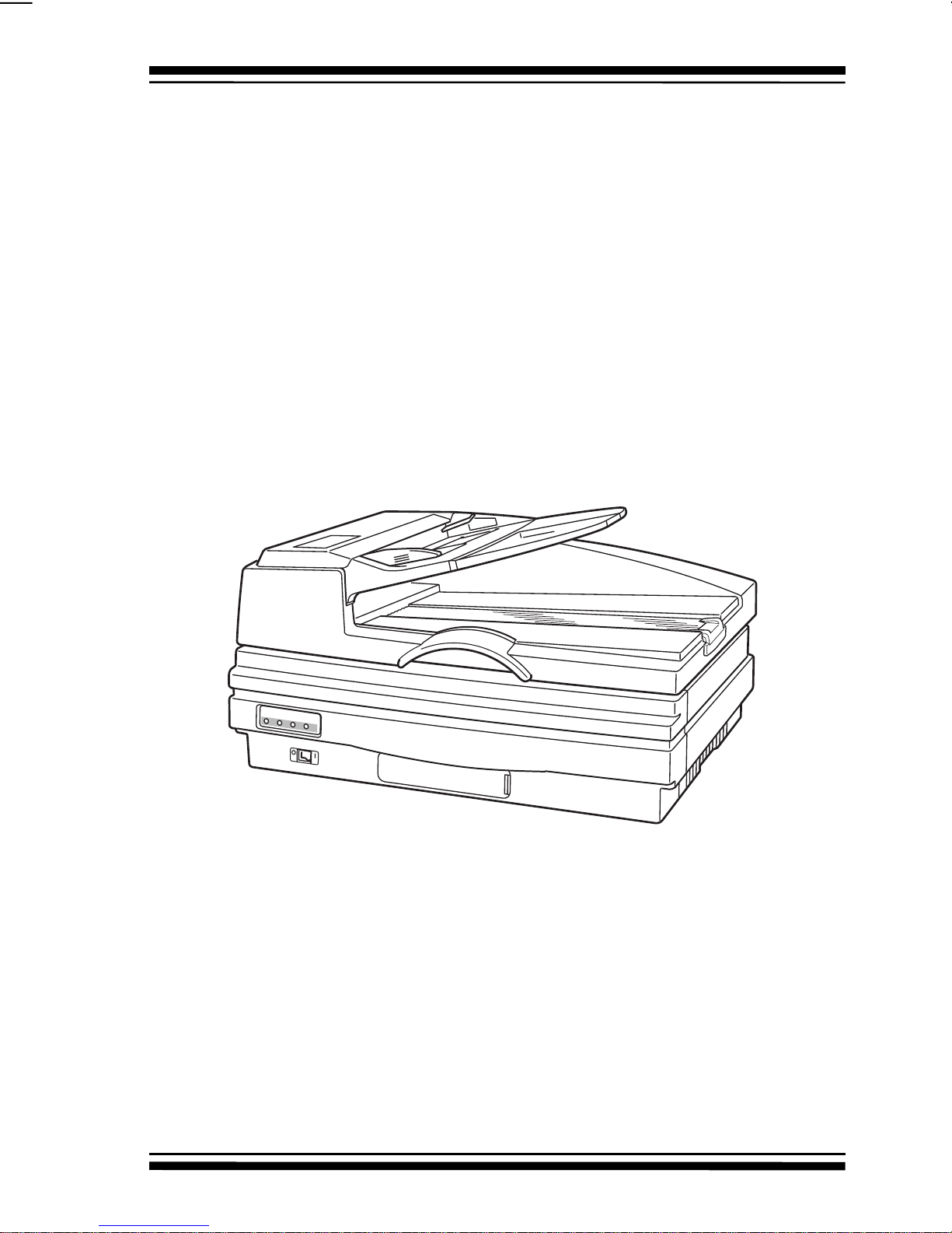
Image Scanner
Operator’s Manual

Error! Reference source not found.
Note to users in the United States of America
This equipment has been tested and found to comply with the limits for a Class B digital
device, pursuant to Part 15 of the FCC Rules. These limits are designed to provide
reasonable protection against harmful interference in a residential installation. This
equipment generates, uses, and can radiate radio frequency energy and, if not installed and
used in accordance with the instructions, may cause harmful interference to radio
communications. However, there is no guarantee that interference will not occur in a
particular installation. If this equipment does cause harmful interference to radio or television
reception, which can be determined by turning the equipment off and on, the user is
encouraged to try to correct the interference by one or more of the following measures:
• Reorient or relocate the receiving antenna.
• Increase the separation between the equipment and receiver.
• Connect the equipment into an outlet on a circuit different from that to which the
receiver is connected.
• Consult the dealer or an experienced radio/TV technician for help.
Warnig
Changes or modifications not expressly approved by the manufacturer could void
the user’s authority to operate the equipment.
Caution
Properly shielded and grounded cable and connector must be used for
connection to host computer in order to meet FCC Emission limits.
Note to users in Canada
This Class B digital apparatus meets all requirement of the Canadian Interference
Causing Equipment Regulations.
Remarque concernant les utilisateurs au Canada.
Cet appareil mumérique de la Classe B respecte toutes les exigences du Réglement
sur le matériel brouilleur du Canada.
Important
Parts of this manual are subject to change without prior notice.
In no event will the company be liable for direct, indirect, special, incidental, or
consequential damages as a result of handling or operating the machine.
Trademarks
Microsoft, Windows, and MS-DOS are registered trademarks of Microsoft
Corporation.
General Notice:
Other product names used herein are for identification purpose only and may be
trademarks of their respective com panies. We disclaim any and all rights in those marks.
Copyright
Copyright, 1997 Ricoh Co., Ltd.
All rights reserved.
No part of this publication may be reproduced, stored in a retrieval system, or
transmitted in any form or by any means, electronic, mechanical, photocopying,
recording, or otherwise, without the prior written permission.

TABLE OF CONTENTS
TABLE OF CONTENTS
SAFETY INFORMATION
IMPORTANT INFORMATION
INTRODUCTION
Overview................................................................................................ix
Features.................................................................................................ix
Options....................................................................................................x
Using this Manual....................................................................................x
Conventions...........................................................................................xi
SETTING UP THE SCANNER
GENERAL GUIDE.................................................................................. 1-1
Front View...........................................................................................1-1
Rear View............................................................................................1-2
Scanner Indicators..............................................................................1-2
CHECKING THE PARTS.......................................................................1-3
SCANNER LOCATION..........................................................................1-4
CONNECTING TO THE HOST..............................................................1-5
To connect to your host ......................................................................1-5
SETTING THE SCSI ID .........................................................................1-8
To set the scanner’s SCSI ID..............................................................1-8
USING TWO SCANNERS IN THE SAME SCSI CHAIN........................1-9
Without SCAM Adapter.......................................................................1-9
With SCAM Adapter............................................................................1-9
To change the setting of DIP switch 1 ................................................1-9
CONNECTING THE POWER CORD ..................................................1-10
To connect the power cord ...............................................................1-10
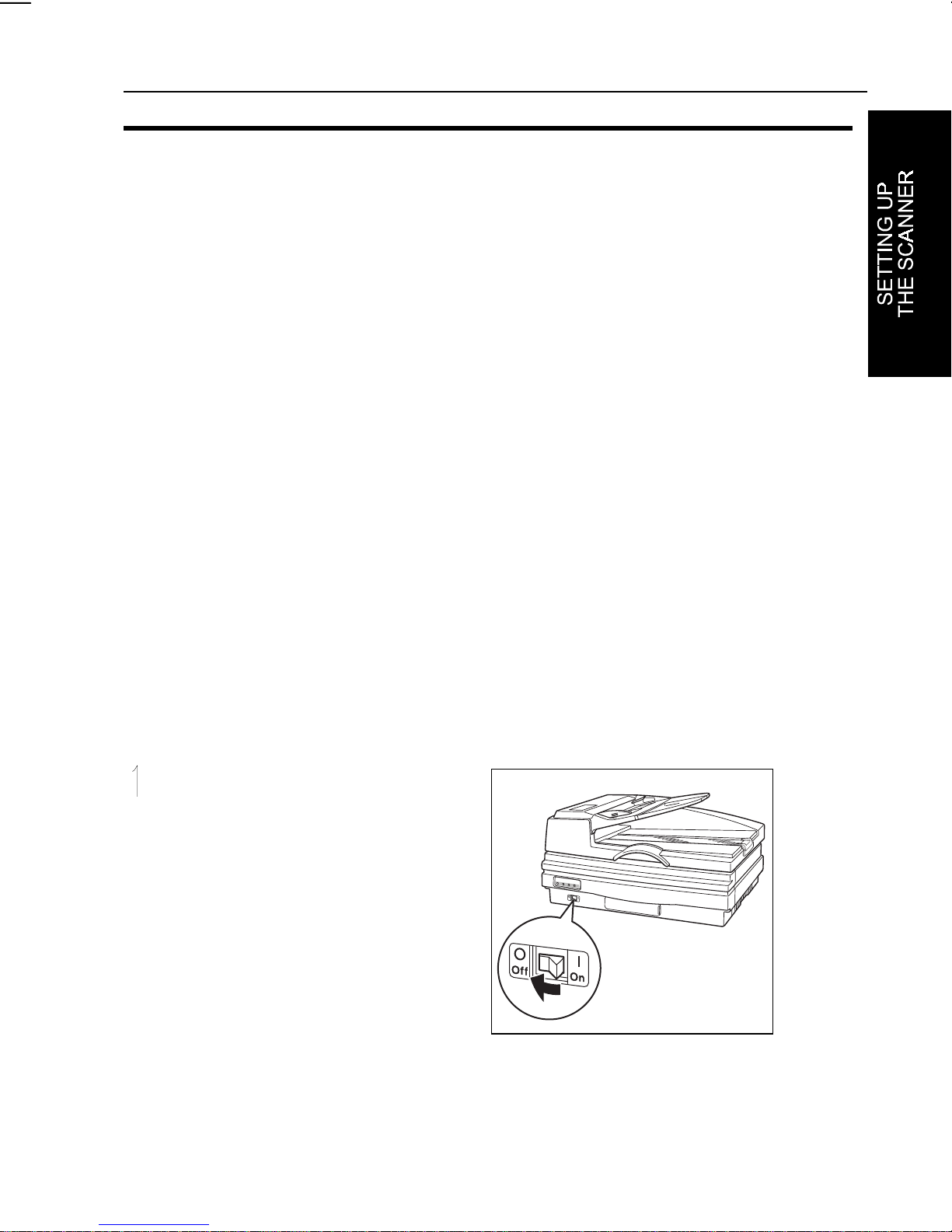
TURNING ON THE SCANNER............................................................1-11
To turn on scanner power.................................................................1-11
DIP SWITCH SETTINGS.....................................................................1-12
Switch 1-SCAM Function..................................................................1-12
Switch 3-Paper Size..........................................................................1-12
Switch 4-IS410 Mode........................................................................1-12
Default Settings.................................................................................1-12
To change DIP switch settings..........................................................1-13
vi

TABLE OF CONTENTS
INSTALLING THE DRIVERS............................................................... 1-14
Installing the TWAIN Scanner Driver................................................ 1-14
Installing the ISIS Scanner Driver..................................................... 1-14
USING THE SCANNER
INTRODUCTION................................................................................... 2-1
PLACING ORIGINALS ON THE SCANNER ......................................... 2-2
USING THE BOOK MODE.................................................................... 2-3
To manually place an original onto the scanner ................................. 2-3
USING THE DOCUMENT FEEDER MODE.......................................... 2-5
To use the document feeder............................................................... 2-6
MAINTENANCE
OVERVIEW............................................................................................ 3-1
CLEANING THE SCANNER.................................................................. 3-2
Contact Glass, Slit Glass,White Sheet,White Bar............................... 3-2
Rollers and Belt................................................................................... 3-3
REPLACING THE ROLLER SET........................................................... 3-5
TROUBLESHOOTING
OVERVIEW............................................................................................ 4-1
Scanner Problems and Solutions ....................................................... 4-1
Document Feeder Cover Open ...................................................... 4-1
Document Feeder Raised............................................................... 4-2
Paper Jam ...................................................................................... 4-2
Paper Misfeed................................................................................. 4-4
System Error................................................................................... 4-5
Other Problems................................................................................... 4-6
SCANNER SPECIFICATIONS
SPECIFICATIONS................................................................................. 5-1
Electrical and Hardware Specifications .............................................. 5-1
Environmental Specifications.............................................................. 5-2
INTERFACES........................................................................................ 5-3
SCSI II Interface ............................................................................. 5-4
RS-232 Interface............................................................................. 5-6
OPTIONS............................................................................................... 5-7
Image Processing Unit........................................................................ 5-7
Operation Panel.................................................................................. 5-7
vii

TABLE OF CONTENTS
A. SCANNER FEATURES
SCANNER FUNCTIONALITY................................................................A-1
Prescan...............................................................................................A-1
Scan....................................................................................................A-2
Scanning composition.........................................................................A-3
Binary Scanning-Threshold.................................................................A-4
Dynamic threshold ..............................................................................A-5
Halftone scanning ...............................................................................A-6
Multi-value scanning ...........................................................................A-7
Area extraction....................................................................................A-8
Section area (multi-area settings) ......................................................A-9
Auto photo/letter................................................................................A-10
Resolution.........................................................................................A-11
Brightness.........................................................................................A-12
Contrast.............................................................................................A-12
Gamma correction ............................................................................A-13
Binary filter........................................................................................A-14
Parameter download.........................................................................A-15
Document size detection...................................................................A-15
Semi-automatic document feed mode ..............................................A-15
IS410 Mode.......................................................................................A-15
GLOSSARY
ACRONYMS ......................................................................................... G-1
TERMS.................................................................................................. G-2
viii

SAFETY INFORMATION
SAFETY INFORMATION
When using your machine, the following safety precautions should always be
followed.
$
WARNING:Ignoring this warning could cause serious injury or
even death.
$
CAUTION: Ignoring this caution could cause injury or damage to
property.
$
Symbols $ means a situation that requires you take care.
B
Do NOT carry out the operation represented by the symbol >.
This example means “Do not take apart.”
C
Symbols C means you MUST perform this operation . This example
means “You must remove the wall plug.”
i

SAFETY INFORMATION
$
>
@
B
WARNINGS:
•
•
•
•
•
•
•
Only connect the machine to the power source
described in the Important Information Section.
Avoid multi-wiring.
Do not damage , break or make any modifications to the
power cord. Do not place heavy objects on it, pull it hard or
bend it more than necessary. These actions could cause an
electric shock or fire.
Do not plug or unplug the power cord with your hands
wet. Otherwise, an electric shock might occur.
Make sure the wall outlet is near the machine and f reely
accessible so that in event of an emergency it can be
unplugged easily.
Do not remove any covers or screws other than those
specified in this manual. Some parts of the machine are at a
high voltage and could give you an electric shock. When the
machine needs to be checked, adjusted, or repaired, contact
your service representative.
Do not take apart or attempt any modifications to this
machine. There is a risk of fire, electric shock, explosion or
loss of sight.
C
>
ii
•
•
•
If the machine looks damaged or breaks down, smoke
is coming out, there is a strange smell or anything looks
unusual, immediately turn off the power switch then unplug
the power cord from the wall. Do not continue using the
machine in this condition. Contact your service
representative.
If metal, liquid or foreign matter falls into the machine,
turn off the power switch, and unplug the power cord.
Contact your service representative. Do not keep using the
machine with a fault or defect.
Do not put any metal objects or containers holding
water (e.g.vases, flowerpots, glasses) on the machine. If the
contents fall inside the machine, a fire or electric shock
could occur.

SAFETY INFORMATION
$
CAUTIONS:
>
C
E
•
•
•
•
•
•
Keep the machine away from humidity and dust. A f ire
or an electric shock might occur.
Do not place the machine on an unstable or tilted
surface. If it topples over, it could cause injury.
When you move the machine, unplug the power cord
from the wall outlet to avoid fire or electric shock.
When the machine will not be used for a long time,
unplug the power cord.
When you pull out the plug from the socket, grip the
plug to avoid damaging the cord and causing fire or electric
shock.
If you use the machine in a confined space, make sure
there is a continuous sir turnover.
@
iii

SAFETY INFORMATION
IMPORTANT INFORMATION
IMPORTANT INFORMATION
1. Read all of these instructions and keep them for later reference.
2. Follow all warnings and instructions marked on the machine.
3. Unplug this machine from the wall outlet before cleaning. Do not use liquid
cleaners or aerosol cleaners.
4. Do not use this machine near water.
5. Do not place this machine on an unstable cart, stand, or table. The
machine could fall and suffer serious damage.
6. Slots and openings in the cabinet and the back or bottom ar e provided for
ventilation; to ensure reliable operation of the machine and protect it from
overheating, these openings must not be blocked or covered. The openings
should never be blocked by placing the machine on a bed, sofa, rug, or
other similar surface. This mac hine should never be placed near or over a
radiator or heat register. This machine should not be placed in a built-in
installation unless proper ventilation is provided.
7. This machine should be operated from the type of power source indicated
on the marking label. If you are not sure of type of power available, contact
your dealer or local power company.
8. This machine is equipped with a 3-wire grounding-type plug, a plug hav ing
a third (grouding) pin. This plug will only fit into a grounding -type outlet.
This is a safety feature. If you are unable to insert the plug into the outlet,
contact your electrician to replace your outlet. Do not defeat the purpose of
the grounding-type plug by removing its grounding pin. (This does not apply
in countries in which a 2-wire, nongrounded type of plug is used.)
9. Do not place this machine where the cord will be walked on.
10. If an extension cord is used with this machine, make sure that the total of
the ampere ratings on the devices plugged into the extension cord does not
exceed the extension cord ampere rating. Als o make sure that the total of
all machines plugged into the wall outlet does not exceed 15 amperes.
11. Never push objects of any kind into this device through cabinet slots as
they may touch dangerous voltage points or short out parts that could result
in a risk of fire or electric shock. Never spill liquid of any kind on the
machine.
iv

SAFETY INFORMATION
IMPORTANT INFORMATION
12. Except as specifically explained in the operator’s manual, do not attempt to
service this device yourself. Opening or removing those covers that are
marked “Do Not Remove” may expose you to dangerous, voltage points or
to other risks. Refer all servicing in those compartment to service personel.
13. Unplug this machine from the wall outlet and refer servicing to qualified
service personal under the following conditions;
A. When the power cord or plug is damaged or frayed.
B. If liquid has been spilled into the machine.
C. If the machine has been exposed to rain or water.
D. If the machine does not operate normally when the operating
instructions are followed. Adjust only those controls that are covered by
the operating instructions since improper adjustment of other controls
may result in damage and will often required extensive work by a
qualified technician to restore the machine to normal operation.
E. If the machine has been dropped or the cabinet has been damaged.
F. If the machine exhibits a distinct change in performance, indicating a
need for service.
14. Make sure that your wall outlet is close to the machine and is easily
accessible.
When you plug the machine into the outlet, make sure the plug is inserted
firmly.
15. The main plug on this machine must be used to disconnect main power.
Two kinds of size notation are employed in this manual.
16. Power Source: 120 V, 60 Hz, more than 10 A
Please make sure to connect the power cord to a power source as above.
17. In accordance with IEC417, this machine us es the following symbol for the
main switch:
means POWER ON
means POWER OFF
v

INTRODUCTION
INTRODUCTION
This manual contains detailed instructions on the operation and maintenance of
your scanner. To obtain maximum versatility from your scanner, you should
carefully read this manual and follow the instructions it provides.
Make sure to read the “Safety Information” section of this manual before using
the scanner. This section contains important information related to user safety
and to preventing equipment problems.
Overview
This scanner allows you to send scanned data to your host computer using a
SCSI II connection.
A variety of powerful features includes an Automatic Document Feeder (ADF)
that allows you to scan multiple pages. Optional equipment includes an Image
Processing Unit.
Features
❐
Automatic Document Feeder (ADF)
❐
Prescanning
❐
Scanning speed of 24 pages per minute (ppm) (200 dpi scanning of A4-size
documents containing black and white line art)
❐
Scanning resolution of 60, 75, and 100 to 800 dots per inch (dpi) (600 dpi
maximum resolution with ADF)
❐
Scanning compositions of line art, halftone, and gray scale.
❐
Area extraction
❐
Section area (multi-area settings)
❐
Brightness, contrast, and threshold value adjustments
❐
Gamma correction settings
❐
Binary filters
❐
Parameter download
❐
Document size detection (with ADF only)
❐
SCAM compatibility
ix

INTRODUCTION
Options
The following are available to you as options that you can add to the basic
components provided with your scanner:
❐
Image Processing Unit
❐
Operation Panel Kit
Using this Manual
This manual explains how to configure and use the scanner. This section
provides short descriptions of the chapters that make up this manual, the
conventions used throughout the manual, and various publications that may be
of further use to you when using the scanner.
This User’s Manual contains the following chapters and appendices:
Chapter 1: Setting Up the Scanner
❐
- provides information on preparing to
use the scanner.
Chapter 2: Using the Scanner
❐
- describes operation of the scanner’s
hardware.
Chapter 3: Maintenance
❐
- tells you what you need to know about keeping
your scanner in good working condition.
Chapter 4: Troubleshooting
❐
- contains information about correcting
problems you might encounter.
Chapter 5: Scanner Specifications
❐
- contains hardware specifications for
the scanner and its interfaces.
Appendix A
❐
- provides illustrated examples of the images your scanner can
produce using various scanning parameters.
A glossary and an index are provided at the end of this manual.
x

Conventions
The following conventions are used throughout this manual:
INTRODUCTION
Square brackets
- the names of the hard keys, soft keys and buttons on the
scanner and on your host computer are enclosed in square brackets. For
example, the
Italics
- names of documents are shown in italics.
[Start]
button.
Note: “Notes” provide general information to help you complete a task or further
understand the text.
xi

INTRODUCTION
General Information
Some of the illustrations of the scanner in this manual may differ slightly from
❐
the actual appearance of your scanner.
Some of the options described in this manual may not be available in your
❐
country. Contact your local dealer for details on the options available to you.
Two kinds of size notation are employed in this manual.
❐
xii

SETTING UP THE SCANNER
SETTING UP THE SCANNER
GENERAL GUIDE
The following illustrations show the names of the various components that
make up the scanner.
Front View
Scanner indicators
Document Feeder Closed
Document table
Output table
Document stopper
Power switch
Front View Document Feeder Open
White sheet
Document home position
Contact glass
1-1
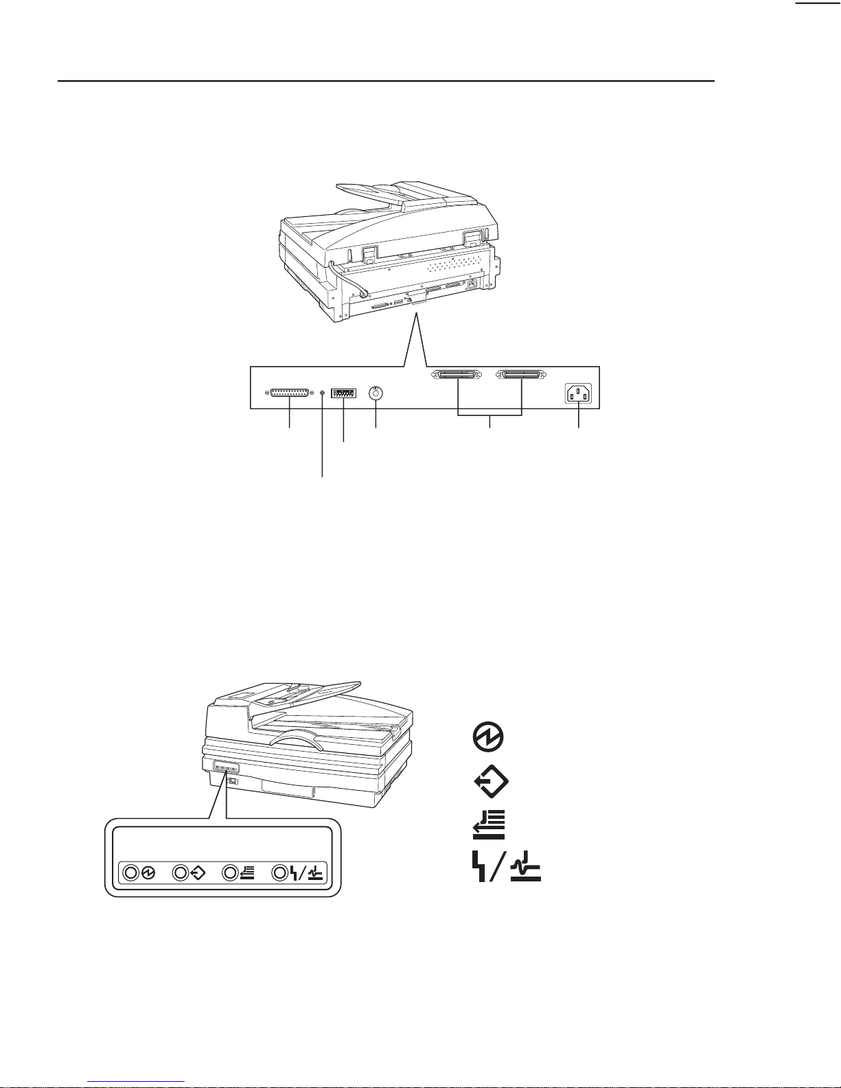
SETTING UP THE SCANNER
Rear View
RS-232C connector
Service switch
Rotary switch
DIP switches
SCSI
connectors
Power cord socket
CAUTION: Do not touch the service switch. This switch is provided
for use by service personnel only.
Scanner Indicators
Power on
Machine busy
Document in place
1-2
Error
SETTING UP THE SCANNER
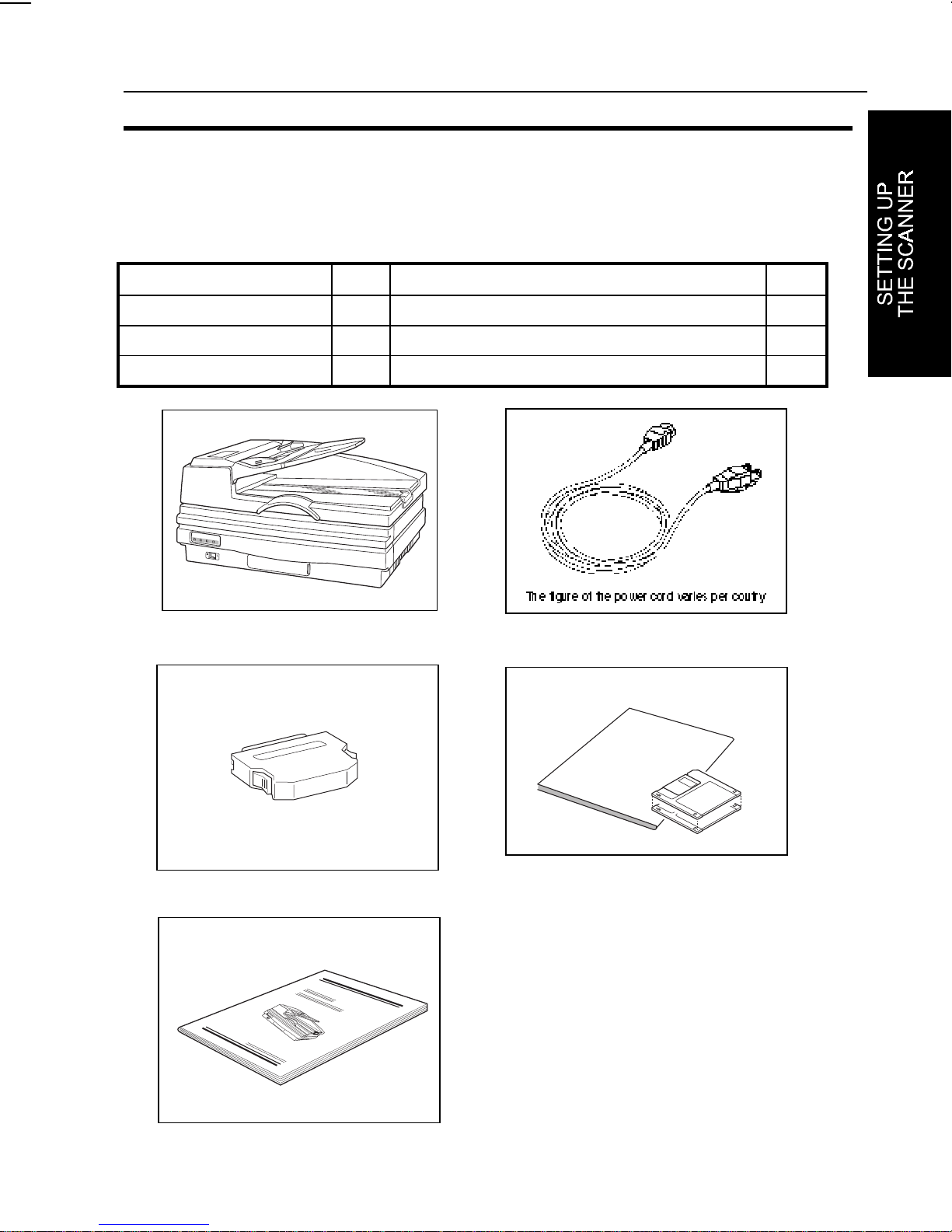
CHECKING THE PARTS
Make sure that you have all the parts shown below in your packing box.
Parts list
Name Q’ty Name Q’ty
Scanner 1 Power cord 1
Terminator 1 driver soft & manual (ISIS) 1set
Operator’s manual 1
Scanner
Terminator
Power cord
driver soft & manual
Operator’s manual
1-3
SETTING UP THE SCANNER
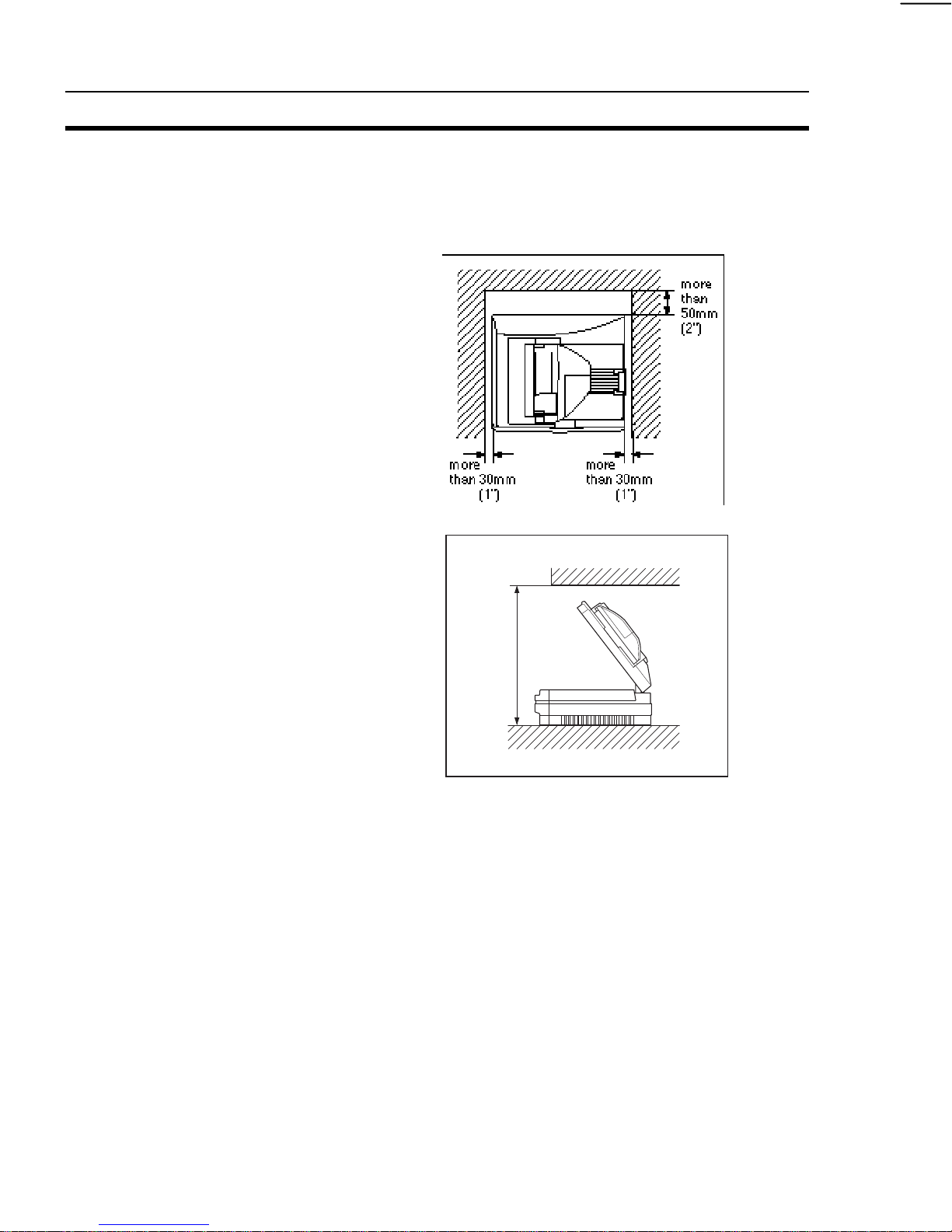
SCANNER LOCATION
Before actually setting up the scanner , take a few minutes to c ons ider wher e y ou
plan to use it. Remember the following points when doing this.
❐
Set up the scanner in an easily
accessible area with temperatures
between 50 and 90 degrees
Fahrenheit (10 to 32 degrees
Celsius) with a relative humidity of
20 to 80 percent.
❐
Make sure that the scanner is in
an area with a minimum clearance
of 600 mm (24”) above, 30 mm
(1”) on each side, 50 mm (2”) in
the rear, and a comfortable
working area in the front.
❐
Place the scanner on a level,
stable, vibrating-free surface.
❐
Place the scanner in an area that
more
than
600mm
(24")
is not exposed to large amounts of
dust and direct sunlight.
❐
Do not place items on top of the
scanner.
CAUTION: Do not place the scanner directly below an air
conditioning or heating vent. Sudden temperature
changes can cause condensation within the scanner.
Note:
For the unpacking and installation of the scanner, refer to the installation
procedure sheet.
1-4
SETTING UP THE SCANNER
CONNECTING TO THE HOST
Use the following procedure to connect the scanner to a host computer using a
SCSI cable.
Note the following important points when making SCSI cable connections.
❐
Turn all devices being connected before making any connections.
❐
The use of cables other than the specified shielded cables or their
equivalents will invalidate your scanner’s certification and can cause
interference levels that exceed the limits established for this equipment.
❐
The total length of the SCSI bus should not exceed six meters.
❐
Either of the scanner’s two SCSI connectors can be used for the connection,
but any unused SCSI connector must be capped with a terminator.
Note:The RS-232C connector is employed only when the optional
Operation Panel is being used.
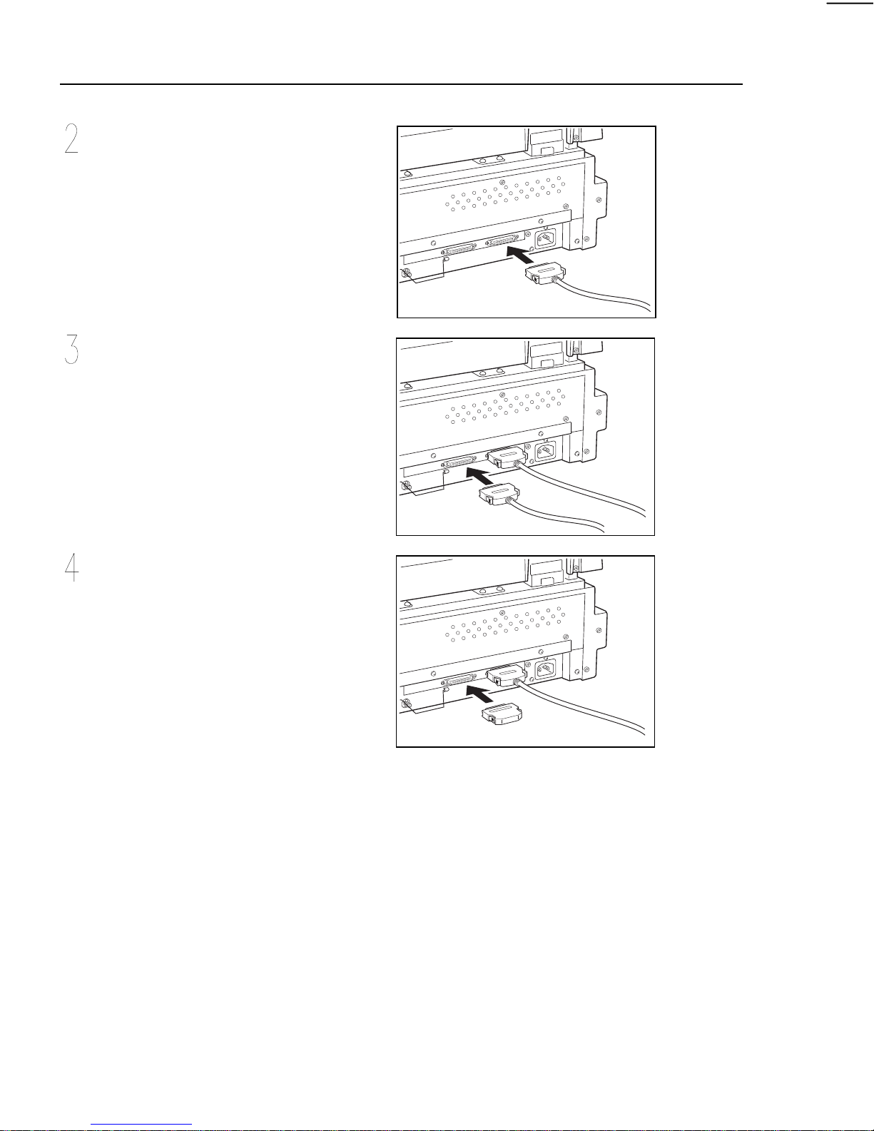
To connect to your host
Make sure that the scanner and
all the other devices in the SCSI
chain are turned off.
1-5
SETTING UP THE SCANNER
Plug one end of the shielded high
density 50-pin SCSI II cable
(ANSI-compliant*1) into the SCSI
II port located on the back of the
scanner.
If you do not plan to connect
anything to the other port, cap it
with a terminator*2.
Plug the other end of the SCSI
cable into the host computer or
other peripheral.
*1 SCSI Cables
There are a variety of different SCSI connector types, including the high-density
50-pin connector, the D-sub 25-pin connector, and the 50-pin flat connector.
Both of the SCSI ports of this scanner require high-density 50-pin connectors.
When choosing a SCSI cable, get one that has a high-density 50-pin connector
on one end (to connect to the scanner), and a connector that meets the needs
of the port of your computer or the device you are connecting to. Also make sure
that the SCSI cable you use is ANSI-compliant.
1-6

SETTING UP THE SCANNER
*2 Terminators
Generally you need to have two terminators at each end of a SCSI chain. If you
connect this scanner at the end of a SCSI chain, you should cap the scanner’s
unused SCSI port with a terminator. If the scanner is located inside of a SCSI
chain that is already terminated, you do not need to terminate the scanner’s
other port.
1-7
SETTING UP THE SCANNER
SETTING THE SCSI ID
Each device in a SCSI chain must have its own unique ID. Use the procedure
below to set the scanner’s SCSI ID.
Note the following important points when setting the scanner’s SCSI ID.
❐
No two devices in the SCSI chain can have the same SCSI ID.
❐
You can change the scanner’s SCSI ID while power is on, but the new setting
does not take effect until you reset the scanner.
❐
Never set 8 or 9 as the scanner’s SCSI ID. Though 8 and 9 settings are
available, you should use IDs 0 through 7 only.
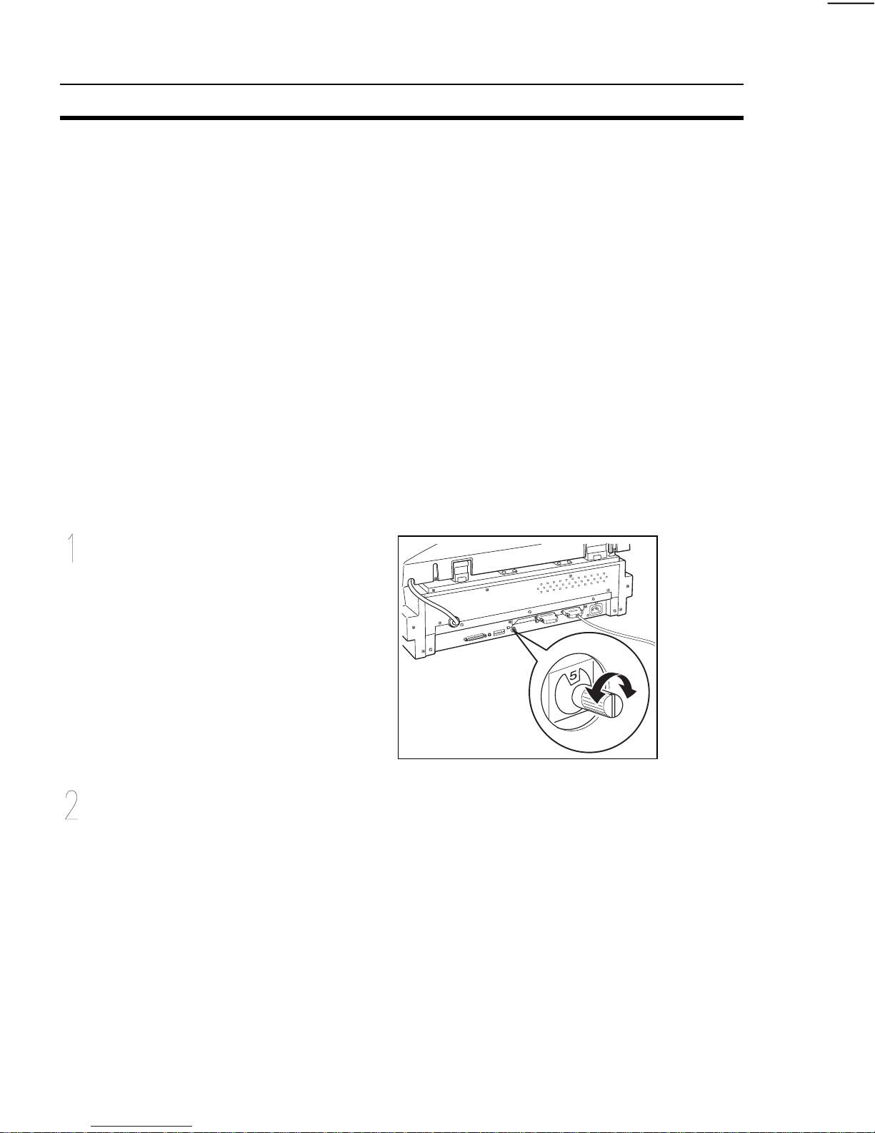
To set the scanner’s SCSI ID
Turn the rotary switch on the
back of the scanner until the
SCSI ID number you want to use
is visible.
If the scanner is on when you
change the SCSI ID, reset it by
turning power off and then back
on again.
Note: Whenever there are two these scanners connected in the same
SCSI chain, be sure to set SW1 of one of the scanner’s DIP
switches to ON.
1-8

SETTING UP THE SCANNER
USING TWO SCANNERS IN THE SAME
SCSI CHAIN
Two of these scanners can be included in the same SCSI chain. In such a
case, you must make sure to correctly make certain settings in order to avoid
conflicts in the chain. The settings you should make depends on whether or not
the computer you care connected to is equipped with a SCAM adapter.
Without SCAM Adapter
In this case, just make sure that each scanner has its own unique SCSI ID.
No other setting is required.
With SCAM Adapter
When the computer you are connecting to is equipped with a SCAM adapter, you
must assign each scanner a unique SCSI ID and also change the setting of DIP
switch 1 for one of the scanners to further protect against data communication
conflict.
•
•
DIP switch 1 of one of the scanners must be OFF (default setting).
DIP switch 1 of the other scanner must be ON.
To change the setting of DIP switch 1
Change the position of DIP
switch1 on the back of the
scanner to ON.
Turn power off and then back on
again.
1-9
 Loading...