

Page 1

Model:
Haokan-P1T
Machine Code:
J089/J098/J099
Field Service Manual
July, 2017
Page 2

Page 3
Important Safety Notices
Warnings, Cautions, Notes
In this manual, the following important symbols and notations are used.
• A Warning indicates a potentially hazardous situation. Failure to obey a Warning could result in
death or serious injury.
• A Caution indicates a potentially hazardous situation. Failure to obey a Caution could result in
minor or moderate injury or damage to the machine or other property.
• Obey these guidelines to avoid problems such as misfeeds, damage to originals, loss of valuable
data and to prevent damage to the machine.
• This information provides tips and advice about how to best service the machine.
General Safety Instructions
For your safety, please read this manual carefully before you use this product. Keep this manual handy
for future reference.
Safety Information
Always obey the following safety precautions when using this product.
Safety During Operation
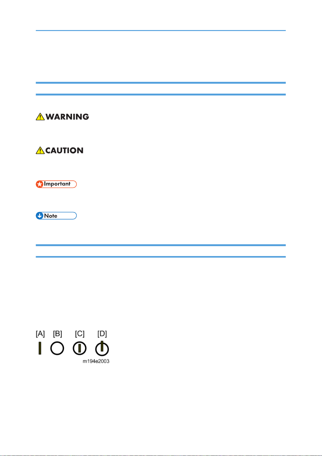
In this manual, the following important symbols and notations are used.
[A]: ON
[B]: OFF
[C]: Push ON/Push OFF
[D]: Standby
1
Page 4

Switches and Symbols
Where symbols are used on or near switches on machines for Europe and other areas, the meaning of
each symbol conforms with IEC60417.
Safety
Prevention of Physical Injury
1. Before disassembling or assembling parts of the machine and peripherals, make sure that the
machine and peripheral power cords are unplugged.
2. The plug should be near the machine and easily accessible.
3. Note that some components of the machine and the paper tray unit are supplied with electrical
voltage even if the main power switch is turned off.
4. Always unplug the power cord from the power source before you move the product. Before you
move the machine, arrange the power cord so it will not fall under the machine.
5. Disconnect all peripheral units (finisher, LCT, etc.) from the mainframe before you move the
machine.
6. If any adjustment or operation check has to be made with exterior covers off or open while the
main switch is turned on, keep hands away from electrified or mechanically driven components.
7. The machine drives some of its components when it completes the warm-up period. Be careful to
keep hands away from the mechanical and electrical components as the machine starts operation.
8. The inside and the metal parts of the fusing unit become extremely hot while the machine is
operating. Be careful to avoid touching those components with your bare hands.
9. To prevent a fire or explosion, keep the machine away from flammable liquids, gases, and
aerosols.
10. Do not use flammable sprays or solvent in the vicinity of the machine. Also, avoid placing these
items in the vicinity of the machine. Doing so could result in fire or electric shock.
11. To avoid fire or explosion, never use an organic cleaner near any part that generates heat.
12. Never remove any safety device unless it requires replacement. Always replace safety devices
immediately.
13. Never do any procedure that defeats the function of any safety device.
14. Modification or removal of a safety device (fuse, switch, etc.) could lead to a fire and personal
injury. Always test the operation of the machine to ensure that it is operating normally and safely
after removal and replacement of any safety device.
15. For replacements use only the correct fuses or circuit breakers rated for use with the machine. Using
replacement devices not designed for use with the machine could lead to a fire and personal
injuries.
2
Page 5

16. When using a vacuum cleaner around the machine, keep others away from the cleaner, especially
small children.
17. NEVER touch the AC circuits on the PSU board, to prevent electric shock caused by residual
charge. Residual charge of about 100V-400V remains in the AC circuits on the PSU board for
several months, even when the board has been removed from the machine after turning off the
machine power and unplugging the power cord.
Observance of Electrical Safety Standards
1. The machine and its peripherals must be installed and maintained by a customer service
representative who has completed the training course on those models with exceptions on some
machines where the installation can be handled by the user.
Safety and Ecological Notes for Disposal
1. Dispose of replaced parts in accordance with local regulations.
2. When keeping used lithium batteries in order to dispose of them later, do not put more than 100
batteries per sealed box. Storing larger numbers or not sealing them apart may lead to chemical
reactions and heat build-up.
3. The danger of explosion exists if a battery of this type is incorrectly replaced. Replace only with the
same or an equivalent type recommended by the manufacturer. Discard used batteries in
accordance with the manufacturer’s instructions.
Safety Instructions for Ink Cartridges
Accidental Exposure To Ink
1. If ink gets on the skin, wash the affected area immediately with soap and cold running water.
2. If ink gets into the eyes, immediately flush the eyes with cold running water. If there are signs
of irritation or other problems, seek medical attention.
3. If ink is swallowed, drink a strong solution of cold water and table salt to induce vomiting.
Seek medical attention immediately.
4. Ink is difficult to remove from fabric. Work carefully to avoid staining clothing when
performing routine maintenance or replacing cartridges.
3
Page 6

Handling and Storing Ink Cartridges
• Ink is flammable. Never store ink cartridges in a location where they will be exposed to high
temperature or an open flame.
1. Always store ink cartridges out of the reach of children.
2. Always store ink cartridges in a cool, dry location that is not exposed to direct sunlight.
Ink Cartridge Disposal
1. Attach the caps to empty ink containers for temporary storage to avoid accidental spillage.
2. Return empty ink cartridges to a local dealer who can accept such items for collection and
recycling or disposal.
3. If the customer decides to dispose of empty ink cartridges, make sure that they are disposed of
in accordance with local laws and regulations.
4
Page 7
Conventions Used in this Manual
Symbols and Abbreviations
This manual uses several symbols.
Symbol What It Means
Clamp
Clip ring
Connector
E-ring
FFC (Flat Film Connector)
Hook
Pointer (cross-reference to another manual section)
Screw
Spring
Standoff
Timing Belt
This manual uses the following abbreviations.
5
Page 8

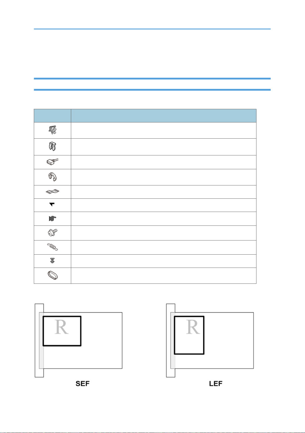
Throughout this service manual, "SEF" denotes "Short Edge Feed" and "LEF" denotes "Long Edge Feed".
Warnings, Cautions, Notes
In this manual, the following important symbols and notations are used.
• A Warning indicates a potentially hazardous situation. Failure to obey a Warning could result in
death or serious injury.
• A Caution indicates a potentially hazardous situation. Failure to obey a Caution could result in
minor or moderate injury or damage to the machine or other property.
• Obey these guidelines to avoid problems such as mis-feeds, damage to originals, loss of valuable
data and to prevent damage to the machine
• This information provides tips and advice about how to best service the machine.
Trademarks
• Apple, AppleTalk, Bonjour, ColorSync, Leopard, Macintosh, Mac OS, Power Mac, Safari and
TrueType are trademarks of Apple Inc., registered in the United States and other countries.
• Citrix, Citrix Presentation Server and Citrix XenApp are either registered trademarks or trademarks
of Citrix Systems, Inc. Firefox® is a registered trademark of the Mozilla Foundation.
• Intel and Intel Core are registered trademarks of Intel Corporation or its subsidiaries in the United
States and other countries.
• Microsoft®, Windows®, Windows Server®, and Internet Explorer® are either registered
trademarks or trademarks of Microsoft Corporation in the United States and/or other countries.
• Monotype is a registered trademark of Monotype Imaging Inc.
• PowerPC® is a registered trademark of International Business Machines Corporation in the United
States and other countries, or both.
• UNIX is a registered trademark in the United States and other countries, licensed exclusively
through, X/Open Company Limited.
• The proper name of Internet Explorer 6 is Microsoft® Internet Explorer® 6.
The proper names of the Windows operating systems are as follows:
• The product names of Windows 7 are as follows:
6
Page 9

Microsoft® Windows® 7 Home Premium
Microsoft® Windows® 7 Professional
Microsoft® Windows® 7 Ultimate
Microsoft® Windows® 7 Enterprise
• The product names of Windows 8.1 are as follows:
Microsoft® Windows® 8.1
Microsoft® Windows® 8.1 Pro
Microsoft® Windows® 8.1 Enterprise
• The product names of Windows 10 are as follows:
Microsoft® Windows® 10 Home
Microsoft® Windows® 10 Pro
Microsoft® Windows® 10 Enterprise
Microsoft® Windows® 10 Education
• The product names of Windows Server 2008 are as follows:
Microsoft® Windows Server® 2008 Standard
Microsoft® Windows Server® 2008 Enterprise
• The product names of Windows Server 2008 R2 are as follows:
Microsoft® Windows Server® 2008 R2 Standard
Microsoft® Windows Server® 2008 R2 Enterprise
• The product names of Windows Server 2012 are as follows:
Microsoft® Windows Server® 2012 Foundation
Microsoft® Windows Server® 2012 Essentials
Microsoft® Windows Server® 2012 Standard
• The product names of Windows Server 2012 R2 are as follows:
Microsoft® Windows Server® 2012 R2 Foundation
Microsoft® Windows Server® 2012 R2 Essentials
Microsoft® Windows Server® 2012 R2 Standard
• The product names of Windows Server 2016 are as follows:
Microsoft® Windows Server® 2016 Datacenter
Microsoft® Windows Server® 2016 Standard
Microsoft® Windows Server® 2016 Essentials
Microsoft® Windows Server® 2016 MultiPoint Premium
7
Page 10

Other product names used herein are for identification purposes only and might be trademarks of their
respective companies. We disclaim any and all rights to those marks.
8
Page 11

TABLE OF CONTENTS
Important Safety Notices................................................................................................................................... 1
Warnings, Cautions, Notes...........................................................................................................................1
General Safety Instructions............................................................................................................................1
Safety...............................................................................................................................................................2
Prevention of Physical Injury................................................................................................................. 2
Observance of Electrical Safety Standards.........................................................................................3
Safety and Ecological Notes for Disposal...........................................................................................3
Safety Instructions for Ink Cartridges ........................................................................................................... 3
Accidental Exposure To Ink.................................................................................................................. 3
Handling and Storing Ink Cartridges...................................................................................................4
Ink Cartridge Disposal...........................................................................................................................4
Conventions Used in this Manual......................................................................................................................5
Symbols and Abbreviations...........................................................................................................................5
Warnings, Cautions, Notes...........................................................................................................................6
Trademarks..................................................................................................................................................... 6
1. Product Information
Specifications....................................................................................................................................................17
Basic Specifications..................................................................................................................................... 17
Main Machine.....................................................................................................................................17
Optional Dryer for Garment Printer (RICOH Rh 100).....................................................................19
Optional Cassettes..............................................................................................................................20
RICOH Design Software (T-shirt Designer).......................................................................................20
RPCS Raster Printer Driver.................................................................................................................. 20
Print Volume, Service Life....................................................................................................................21
Operation Specifications.............................................................................................................................21
Printing Operation...............................................................................................................................21
Print Speed and Resolution.................................................................................................................22
Control Boards.............................................................................................................................................22
Controller............................................................................................................................................. 22
Supported Utilities........................................................................................................................................23
Overview.......................................................................................................................................................... 25
Machine Codes and Peripherals Configuration........................................................................................25
Main Machine.....................................................................................................................................25
9
Page 12

Options................................................................................................................................................ 25
Diagram............................................................................................................................................... 26
Consumables................................................................................................................................................26
Ink Cartridges...................................................................................................................................... 26
Ink Collector Unit.................................................................................................................................27
Others...................................................................................................................................................28
Names of Components................................................................................................................................28
2. Installation
Preparation....................................................................................................................................................... 31
Environment..................................................................................................................................................31
Choosing a Location....................................................................................................................................31
Minimum Space Requirements................................................................................................................... 33
Power Source............................................................................................................................................... 33
Precautions when Moving the Machine.................................................................................................... 33
Using the Operation Panel.............................................................................................................................. 35
Printer Display Summary............................................................................................................................. 36
Operation Panel: Cartridge replacement indicator......................................................................... 36
Operation Panel: Waste Ink Full Indicator........................................................................................37
Display Menu Summary..............................................................................................................................38
User Menu Mode................................................................................................................................38
Access to menus during an error........................................................................................................45
Installation.........................................................................................................................................................46
Accessory Check..........................................................................................................................................46
Important Information...................................................................................................................................... 49
Checklist before Moving the Printer........................................................................................................... 49
If the Printer Is Not Used Frequently…........................................................................................................49
3. Preventive Maintenance
PM Table...........................................................................................................................................................51
Service Call Procedures.............................................................................................................................. 51
4. Replacement and Adjustment
Before Replacing Parts.....................................................................................................................................53
Covers............................................................................................................................................................... 54
Cover Names...............................................................................................................................................54
10
Page 13

Order of Cover Removal.............................................................................................................................55
Front Right Cover......................................................................................................................................... 55
Right Lower Cover........................................................................................................................................56
Right Cover...................................................................................................................................................56
Re-assembly.........................................................................................................................................58
Port Cover.....................................................................................................................................................60
Left Lower Cover.......................................................................................................................................... 60
Left Cover......................................................................................................................................................60
Canopy Cover............................................................................................................................................. 61
Front Cover, Operation Panel Board.........................................................................................................62
Re-assembly.........................................................................................................................................65
Rear Top Cover............................................................................................................................................67
Rear Transport Cover.................................................................................................................................. 67
Rear Cover, Top Cover............................................................................................................................... 68
Top Cover Only...................................................................................................................................71
Front Lower Cover....................................................................................................................................... 71
Right Guide Rail Cover................................................................................................................................72
Left Guide Rail Cover...................................................................................................................................75
Cassette Stand............................................................................................................................................. 78
Ink Collector Unit..............................................................................................................................................81
Before You Begin......................................................................................................................................... 81
Replace the Ink Collector Unit.................................................................................................................... 82
Maintenance Unit, Right Ink Sump................................................................................................................. 84
Maintenance Unit........................................................................................................................................ 84
Right Ink Sump..............................................................................................................................................86
Encoders........................................................................................................................................................... 88
Vertical Encoder Wheel.............................................................................................................................. 88
Horizontal Encoder Strip.............................................................................................................................92
Reinstallation........................................................................................................................................94
Boards...............................................................................................................................................................99
PSU................................................................................................................................................................99
Printer Engine CTL Board.......................................................................................................................... 100
Before Replacement......................................................................................................................... 100
11
Page 14

CTL Board Replacement...................................................................................................................101
After Replacement............................................................................................................................ 103
Wireless LAN Board................................................................................................................................. 105
Relay Board............................................................................................................................................... 106
Lift Board.................................................................................................................................................... 107
Motors............................................................................................................................................................ 114
Horizontal Motor.......................................................................................................................................114
Vertical Motor............................................................................................................................................115
Lift Motor Unit............................................................................................................................................ 117
Applying Grease When Installing the Lift Motor........................................................................... 120
Fan.................................................................................................................................................................. 122
Sensors, Switches.......................................................................................................................................... 123
Vertical Encoder Sensor............................................................................................................................123
Ink Level Sensor......................................................................................................................................... 123
Air Purge Detection Switch....................................................................................................................... 126
Top Cover Switch...................................................................................................................................... 127
Front Right Cover Switch...........................................................................................................................128
Temperature/Humidity Sensor.................................................................................................................129
Interlock Switch..........................................................................................................................................129
Cassette Size Sensor.................................................................................................................................130
Height Sensor ........................................................................................................................................... 132
Cassette Carriage HP Sensor (Front).......................................................................................................133
Cassette Carriage HP Sensor (Rear)....................................................................................................... 133
Lift Tray HP Sensor ....................................................................................................................................134
Carriage Unit................................................................................................................................................. 136
Removing the Carriage Unit..................................................................................................................... 136
Ink Supply Unit...........................................................................................................................................136
Installing the Ink Supply Unit............................................................................................................139
Ink Tube Guide.......................................................................................................................................... 141
Carriage.....................................................................................................................................................142
Installing the Carriage Unit.............................................................................................................. 144
Lock the Carriage............................................................................................................................. 147
After Replacing the Carriage Unit............................................................................................................148
12
Page 15

Print Head Cleaning and Adjustment...........................................................................................................150
Preparing for Test Printing.........................................................................................................................150
Nozzle Check............................................................................................................................................151
Color Demo Print....................................................................................................................................... 152
Print Head Cleaning..................................................................................................................................153
Print Head Flushing....................................................................................................................................154
Head Position.............................................................................................................................................155
Registration................................................................................................................................................ 157
Cleaning......................................................................................................................................................... 159
Height Sensor Cleaning............................................................................................................................159
Horizontal Encoder Sensor Cleaning .....................................................................................................160
Preparation........................................................................................................................................161
Cleaning............................................................................................................................................162
Clean Internals...........................................................................................................................................163
When cleaning of the interior fails.................................................................................................. 166
Adjusting the Height of the Cassette manually............................................................................................168
Refurbishing....................................................................................................................................................170
Clean the Machine....................................................................................................................................170
5. System Maintenance Reference
Service Mode and Engine Maintenance Mode......................................................................................... 171
Service Mode............................................................................................................................................ 171
Entering/Exiting Service Mode.......................................................................................................171
Engine Maintenance (SP) Mode..............................................................................................................175
Entering/Exiting SP Mode............................................................................................................... 175
Using SP Mode Menus.................................................................................................................... 175
Bit Switch Settings......................................................................................................................................177
SP Mode Service Tables............................................................................................................................... 180
SP Table Key..............................................................................................................................................180
SP1-XXX (Feed)......................................................................................................................................... 181
SP2-XXX......................................................................................................................................................184
SP3-XXX (Process)..................................................................................................................................... 184
SP4-XXX......................................................................................................................................................187
SP5-XXX (Mode)....................................................................................................................................... 187
13
Page 16

SP6-XXX......................................................................................................................................................191
SP7-XXX (Data Log).................................................................................................................................. 191
SP8-XXX......................................................................................................................................................199
SP9-XXX (Others)...................................................................................................................................... 199
Status Reports.................................................................................................................................................201
1. Page Counter........................................................................................................................................ 202
2. Config. List (System Summary).............................................................................................................203
3. Service Summary.................................................................................................................................. 204
4. Engine Summary Chart.........................................................................................................................204
Firmware Updates......................................................................................................................................... 209
Operating Environment and Other Requirements.................................................................................. 209
Update Cautions....................................................................................................................................... 210
Preparation................................................................................................................................................ 211
Firmware Update (Bidirectional-Enabled).............................................................................................. 212
Firmware Update (Bidirectional-Disabled)............................................................................................. 214
How to check the current firmware version.................................................................................... 214
How to Update the Firmware When Bidirectional Communication is Disabled......................... 215
6. Troubleshooting
Image Problems............................................................................................................................................. 219
Basic Check Points and Specifications.................................................................................................... 219
Problems and Solutions.............................................................................................................................221
Error Codes.................................................................................................................................................... 229
Operation Panel Display.......................................................................................................................... 229
Operation Panel Messages......................................................................................................................231
Service Call Conditions.............................................................................................................................235
SC code display patterns and how to clear them..........................................................................235
Service Call Code Tables......................................................................................................................... 236
Jam Codes................................................................................................................................................. 266
Jam Codes.........................................................................................................................................266
Jammed garment location................................................................................................................267
Status Monitor Messages......................................................................................................................... 268
7. Detailed Description
Electrical Components...................................................................................................................................273
14
Page 17

Parts Layout................................................................................................................................................273
Electrical Component Summary...............................................................................................................275
Print Heads..................................................................................................................................................... 281
Print Head Configurations........................................................................................................................ 281
Print Head Detailed Configuration...........................................................................................................281
Cassette/Cassette Carriage Movement......................................................................................................283
Basic Operation........................................................................................................................................ 283
Initialization when Turning on Power (Preparation for Mounting Cassette).........................................284
Detecting Height (Unevenness due to Wrinkles and Bulges) of Printing Media.................................. 285
Printing........................................................................................................................................................286
15
Page 18

16
Page 19

1. Product Information
Specifications
Basic Specifications
Main Machine
Items Specifications
Configuration Desktop
Printing Method On-Demand piezo inlet GEL JET Ink Printing Technology with pigment-
base ink (4 colors)
Resolution (dpi, bit/pixel) Max. 1200x1200dpi equivalent
Print Speed (when printing
the whole A4 area in black)
Nozzles • Black: 192 nozzles
Warm-up Time Less than 35 sec.
Printable area A4 standard tray 291 × 204 mm (11.5 × 8.0 inches)
Fabric thickness • A4 standard tray and A5 tray (option)
Number of loadable
cassettes
• Speed priority mode
1 minute 20 seconds or less (after pressing the Start button)
• Quality priority mode
2 minutes 30 seconds or less (after pressing the Start button)
• Cyan, magenta, and yellow: 192 nozzles per color
A5 tray (option) 204 × 142 mm (8.0 × 5.6 inches)
Multi tray*3 (option) 291 × 204 mm (11.5 × 8.0 inches)
7 mm (0.27 inches)
• Multi tray (option)
35 mm (1.37 inches)
1 cassette
*3
17
Page 20

1. Product Information
Power source • EU/Asia/China
220-240 V: 50/60 Hz 0.6 A (with all options installed)
• NA
100-120 V: 60 Hz 1 A (with all options installed)
Power consumption*1 With consumables Ready (EU/Asia/China) 9.0W
Ready (NA) 9.2W
During printing (EU/Asia/
China)
During printing (NA) 18.1W
Maximum (EU/Asia/China) 47W
Maximum (NA) 47W
With all options
Maximum (EU/Asia/China) 47W
installed
Maximum (NA) 47W
Energy Saver mode Reduced power consumption in Energy Saver
mode*2
Time to switch into Energy Saver mode 5 min.
Time to switch out from Energy Saver mode*2 2.9 sec.
External dimensions
(W × D × H)
• Standby:
399 × 698.2 × 292.5 mm (15.7 × 26.9 × 11.5 inches)
• During printing:
17.7W
1.8W (EU/
Asia/China)
1.7W (NA)
18
399 × 760.3 × 292.5 mm (15.7 × 29.9 × 11.5 inches)
Weight 22 kg (45.5 lb.) or less
Interface • USB 2.0 high speed
• Ethernet (10Base-T, 100Base-TX)
• Wireless LAN (IEEE 802.11 b/g/n)
Page 21

Specifications
Wireless LAN Transmission
Specification
Data Transfer
Speed
Frequency
Range
Transmission
Mode
Based on IEEE 802.11b/g/n
Auto select from the following speeds:
• 802.11b
1, 2, 5.5, 11 (Mbps)
• 802.11g
6, 9, 12, 18, 24, 36, 48, 54 (Mbps)
• 802.11n
6.5, 7.2, 13, 13.5, 14.4, 15, 19.5, 21.7,26,
27, 28.9, 30, 39, 40.5, 43.3, 45, 52, 54,
57.8, 58.5, 60, 65, 72.2, 81, 90,108, 120,
121.5, 135, 150 (Mbps)
• EU/Asia/China:
2412 to 2472 Mhz (1 to 13 Channels)
• NA:
2412 to 2462 Mhz (1 to 11 Channels)
Infrastructure mode
Printer language RPCS Raster
To avoid unnecessary power consumption, disconnect the power plug from the wall outlet. (Unplug the
*1:
power plug only after making sure the power lamp is off.) Power Consumption may differ depending on the
conditions and environment of the machine.
The time it takes to switch out from energy saving functions and power consumption may differ depending on
*2:
the conditions and environment of the machine.
*3: RICOH Tray for Multi Purpose Type 1 (J364)
Optional Dryer for Garment Printer (RICOH Rh 100)
Items Specifications
Power source
Power consumption 1,000 W
EU/Asia/China: 220-240 V: 50/60 Hz
NA: 110-127 V: 50/60 Hz
19
Page 22

1. Product Information
Items Specifications
External dimensions (W × D × H) 399 × 600 × 200 mm (15.8 × 23.7 × 7.9 inches)
Weight 16.5 kg (approx. 36.4 lb.)
Optional Cassettes
Items Specifications
• A5 tray
External dimensions (W × D ×
H)
Weight
242.2 × 409.2 × 97.9 mm (9.5 × 16.1 × 3.9 inches)
• Multi tray
242.2 × 409.2 × 84.9 mm (9.5 × 16.1 × 3.3 inches)
• A5 tray
2.13 kg (4.7 lb.)
• Multi tray
1.62 kg (3.6 lb.)
RICOH Design Software (T-shirt Designer)
Items Specifications
Supported device
Supported operating system
Windows tablets (with 10-inch touch panel)
Device with Mac OS (iMac, MacBook, Mac mini, etc.)
Windows 10 (32-bit version)
Mac OS X 10.10 and later versions
RPCS Raster Printer Driver
Items Specifications
Available Operating Systems
20
Windows: Windows 7/8.1/10 and Windows Server 2008/2008
R2/2012/2012 R2/2016
Macintosh: Mac OS X 10.8 and later versions
Page 23
Print Volume, Service Life
Duty 3,000 prints
Monthly Volume Ave. 200 prints
Estimated Service Life 5 years, or 60K prints
Operation Specifications
Printing Operation
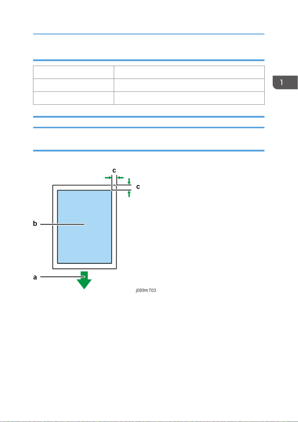
Print Area
Specifications
a. Front of the Cassette
b. Printable Area
c. Windows: 3 mm (0.12 inches), Mac: 3 mm (0.12 inches)
The printing ranges of each cassette are as follows:
• A4 standard tray: 291 × 204 mm (11.5 × 8.0 inches)
• A5 tray: 204 × 142 mm (8.0 × 5.6 inches)
• Multi tray: 291 × 204 mm (11.5 × 8.0 inches)
Functions that can be adjusted with the driver
• It is possible to select [Fine], [Speed], and [Vivid] in Print Quality for each print media
21
Page 24

1. Product Information
• Garment Settings (Size, Fit to Garment Size, Portrait/Landscape, Garment Type)
• Color/Monochrome selection
• Adjust images (Adjust Photographs, Smooth Low Resolution Images)
• Number of copies
• Advance settings for image quality (Brightness, Contrast, Saturation, RGB Revision, etc.)
• Color Profile Settings (Type, On/Off)
• Printable Area Settings (3 mm margin)
Print Speed and Resolution
Print Mode dpi RPCS–R Diver
Fine mode 1200 x 1200 1 minute 20 seconds or less
Speed mode 600 x 600 2 minutes 30 seconds or less
Vivid mode 600 x 600 NA
*1: When printing the whole A4 area in black.
*2: After pressing the Start button.
Control Boards
Controller
CPU SH2A
SoC ZICO
RAM SDRAM: 32MB
Program ROM On Board: 4MB
*1, *2
*1, *2
22
Font ROM None
EEPROM 4KB
Optional EEPROM slot None
PDL RPCS Raster
Page 25

Connectivity
Specifications
Host Interface(Std) USB 2.0 High Speed, 10Base-T/100Base-TX
Network Protocol TCP/IP
MIB Support Private:
Ricoh Original
Standard:
RFC1213 (MIB-II)
RFC1514/RFC2970 (Host Resource MIB)
RFC1759 (Printer MIB)
RFC3412 (MPD-MIB)
RFC3413 (Target-MIB, Norification-MIB)
RCF3414 (USM-MIB)
RFC3415 (VACM-MIB)
RFC3584 (COMMUNITY-MIB)
Printer Working Group Candidate Standard 5107.1-2005
(Printer Port Monitor MIB 1.0)
Networking Operating Systems • Windows: Windows 7/8.1/10 and Windows Server
2008/2008 R2/2012/2012 R2/2016
• Macintosh: Mac OS X 10.8 and later versions
Note: Mac driver included on CD-ROM (The supported languages are English, French, German and
Japanese.).
Supported Utilities
Bundled T-shirt Designer
Software for designing and printing on T-shirt and tote bag
fabric.
Web The following software can be downloaded.
• Smart Device Monitor for Admin
• Smart Device Monitor for Client
23
Page 26

1. Product Information
Optional • Remote Communication Gate S Pro
• Smart Device Monitor for Admin Accounting Report
Package
• Desk Top Binder Lt
24
Page 27

Overview
Overview
Machine Codes and Peripherals Configuration
Main Machine
There are 3 different models. However, they each have the same product name. There are absolutely no
differences in functionality, as the only difference is the exterior color.
Machine
Code
J089 RICOH Ri 100 White Not supported Supported
J098 RICOH Ri 100 Pink Not supported Supported
J099 RICOH Ri 100 Green Not supported Supported
Product Name Exterior color Printing on paper NIC
Options
Code Product Name Remarks
Dryer for garment printer.
J361 RICOH Rh 100
J362 RICOH Tray for Standard Size Type 1
J363 RICOH Tray for Small Size Type 1 A5 tray
J364 RICOH Tray for Multi Purpose Type 1
A heat press for fixing printed images
onto fabric.
Same as the supplied standard (A4)
tray.
This tray is for fabrics on which
printing cannot be performed with
the A4 standard tray and A5 tray.
25
Page 28
1. Product Information
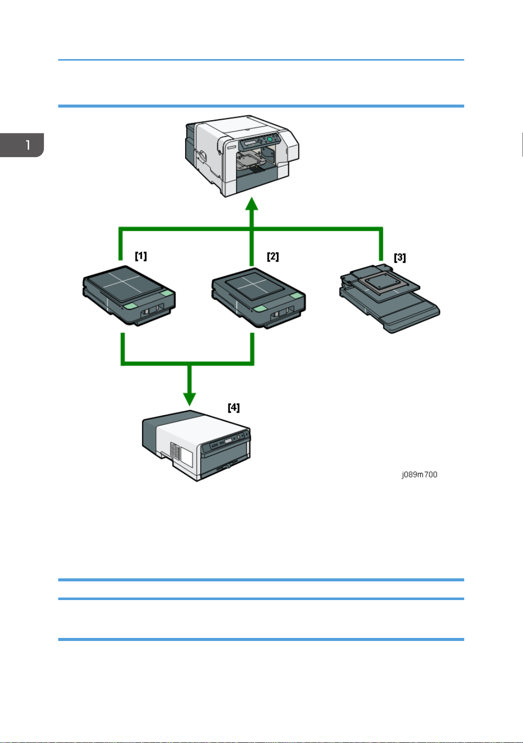
Diagram
[1]: RICOH Tray for Standard Size Type 1 (standard/optional)
[2]: RICOH Tray for Small Size Type 1 (optional tray)
[3]: RICOH Tray for Multi Purpose Type 1 (optional tray)
[4]: RICOH Rh 100 (optional dryer for garment printer)
Consumables
Ink Cartridges
Always use the starter cartridges shipped with the machine to initialize ink supply at installation. Never
install used ink cartridges to initialize ink supply at installation.
26
Page 29

Code Product Name Remarks
Overview
J922-08
J922-24 (for China)
J922-09
J922-25 (for China)
J922-10
J922-26 (for China)
J922-11
J922-27 (for China)
J922-12
J922-28 (for China)
J922-13
J922-29 (for China)
J922-14
J922-30 (for China)
J922-15
J922-31(for China)
RICOH Garment Ink Cartridge K (Hi Yield) Type 1
RICOH Garment Ink Cartridge C (Hi Yield) Type 1
RICOH Garment Ink Cartridge M (Hi Yield) Type
1
RICOH Garment Ink Cartridge Y (Hi Yield) Type 1
RICOH Garment Ink Cartridge K Type 1
RICOH Garment Ink Cartridge C Type 1
RICOH Garment Ink Cartridge M Type 1
RICOH Garment Ink Cartridge Y Type 1
These are mediumsize cartridges.
These are small-size
cartridges.
Ink Collector Unit
The ink collector unit is installed on the right side of the machine behind the right front door below the ink
supply unit.
Code Product Name
J923-00 RICOH Ink Collection Unit Type 1*
*This ink collector unit is only for this machine. The units for SG 3110DN / SG 3110DNw, or the other
Geljet machines have the same appearance, but they are incompatible with this machine due to a
software detection.
27
Page 30
1. Product Information
Others
Code Product Name
J924-00 RICOH Heat Resistant Paper Type 1
J922-36 RICOH Cleaning Cartridge K Type 1
J922-37 RICOH Cleaning Cartridge C Type 1
J922-38 RICOH Cleaning Cartridge M Type 1
J922-39 RICOH Cleaning Cartridge Y Type 1
J927-00 RICOH Cleaning Tool Type 1
J928-00 RICOH Cleaning Absorber Type 1
J929-00 RICOH Cleaning Stick Type 1
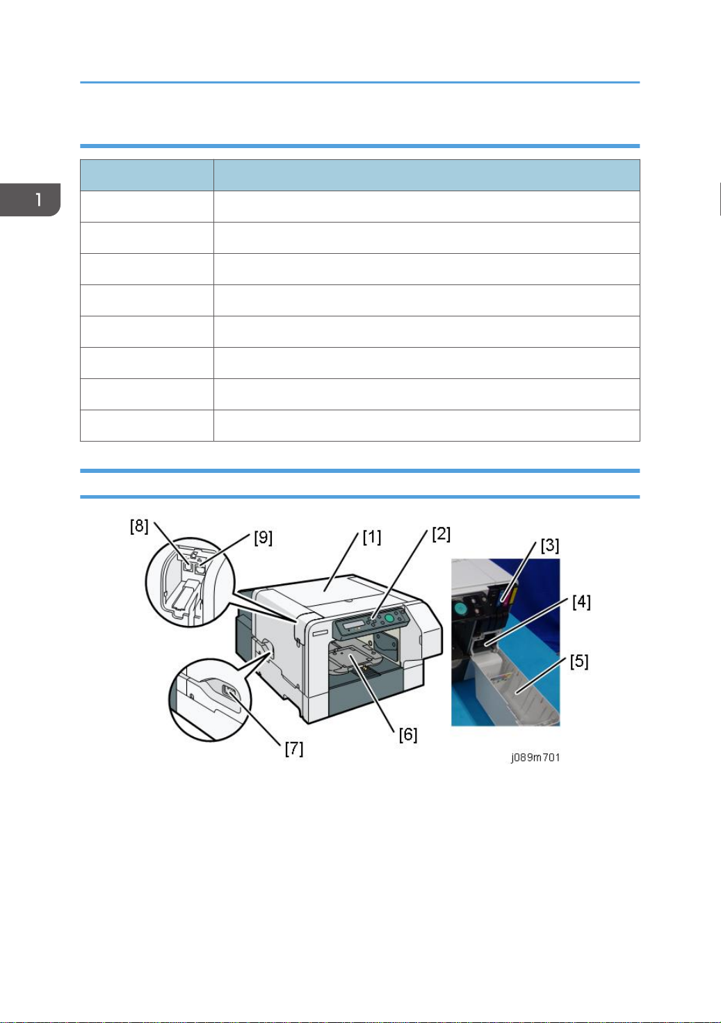
Names of Components
1. Top cover
Open to remove the fabric or foreign object, or to clean the maintenance unit.
2. Operation panel
Operation keys and the 2-line LCD.
3. Ink cartridges (K), (C), (M), (Y)
28
Supply ink to the print heads.
Page 31

4. Ink collector unit
Pull out the ink collector unit when it needs to be replaced, or before servicing the printer.
5. Front right cover
Covers the ink cartridges and the ink collector. Open only when installing or replacing ink
cartridges, or when pulling out the ink collector unit. Otherwise, this door should remain closed. A
small switch detects when this cover is open and closed. The door must be closed for the printer to
operate.
6. Cassette stand
The cassette is set here. The cassette is fed to the inside of the main unit when printing.
7. Power inlet
The connection point for the power cord. Use only the detachable power cord provided with the
printer. Make sure you ground (earth) the head of the plug at the power source.
8. USB port
This is the connection point for the USB cable from the PC.
9. Ethernet port
Overview
The port for the Ethernet cable. The NIC is mounted on the controller board.
29
Page 32

1. Product Information
30
Page 33

2. Installation
Preparation
Environment
• White area: Permissible Range
• Blue area: Recommended Range
Set up the machine in a location that meets these minimum requirements:
Temperature Range: 10°C to 45°C (50°F to 113°F)
Humidity Range: 5% to 90% RH
Ambient Illumination: Less than 2,000 Lux (never expose to direct sunlight).
Choosing a Location
1. Always install the machine:
• On a sturdy, level surface.
• Where it will not become damp.
31
Page 34

2. Installation
2. Make sure the machine is never exposed to:
• Extreme changes from low to high temperature or high to low temperature.
• Cold or cool air directly from an air conditioner.
• Heat from a space heater.
3. Never install the machine in areas near:
• Dust, lint, or corrosive fumes.
• Strong vibration.
4. Do not use the machine at any location higher than 2,500 m (8,200 ft) above sea level.
5. Set up and use the machine on a sturdy, level surface.
• Place a carpenter's level on the machine front-to-back, and side-to-side and confirm that it is
level.
• Variations between the front/back and left/right level readings should be less than 2
degrees.
Required Software Environment
Software • Microsoft Windows 7/8.1/10
• Microsoft Windows Server 2008/2008 R2/2012/2012 R2/2016
• Mac OS X 10.8 and later versions
• PC/AT-compatible computer with USB or network interface
• Macintoshes that are PowerPC G3 or higher with USB port or network port
Hardware
• Macintoshes that are Intel Core Duo or higher with USB port or network port
• 80-100 MB of HDD space available
Note: Mac driver included on CD-ROM (The supported languages are English, French, German and
Japanese.).
32
Page 35

Minimum Space Requirements
a. At least 27 cm (10.7 inches)
Preparation
b. At least 10 cm (4 inches)
c. At least 45 cm (17.8 inches)
d. At least 3 cm (1.2 inches)
e At least 0 cm (0 inches)
Power Source
North America 100-120V: 60Hz 1.0A (when all options are installed)
Europe 220-240V: 50/60Hz 0.6A (when all options are installed)
Precautions when Moving the Machine
• The machine weighs around 22kg (48.5lb.).
• Two or more people are required to lift the printer.
33
Page 36

2. Installation
• When moving the printer, lift it slowly so that you do not strain yourself. Lifting the printer forcibly or
handling it roughly will risk injury to yourself and damage to the printer.
Be cautious of the following points when moving the machine for repairs or transferring it to a repair
facility etc.
• Make sure the ink cartridges remain set in position.
• Make sure that the cover and tray do not open or come off by sealing them down with tape.
• Do not tilt or apply shocks to the machine. If the machine is tilted, ink may spill out of the machine.
• After moving the machine, check the quality of images by performing a test print, and clean the
machine if necessary.
34
Page 37

Using the Operation Panel
Using the Operation Panel
Here is a brief description of how to use the keys on the printer operation panel. This information is
provided as a quick summary of important information described in the Operating Instructions.
Key Summary Table
Key/Indicator What It Does
1 Display Displays the current machine status and messages.
2 Escape Press this key to return to the previous condition on the display.
3 , /Menu Use these keys to increase or decrease values on the display when
making settings.
Keep the key pressed to quicken scrolling, and increase or decrease
values on the display in units of 10. To apply this function: under
[Maintenance], set [Key Repeat] to [On].
4 #Enter Press this key to execute menu items selected on the display.
5 Start Start printing. LED of the [Start] key lights up when the machine is ready
to start printing and flashes when it is printing.
6 Tray Press this key to move the cassette forcibly to the front.
7 Power lamp Lights up when the power is on.
Flashes when the machine is receiving data from a computer or if there
is data to be printed.
8 Alert indicator Lights up or blinks whenever a machine error occurs.
If the red light is on, follow the instructions that appear on the display.
35
Page 38

2. Installation
Key/Indicator What It Does
9 Cartridge
replacement
indicator
10 Waste ink full
indicator
11 Adjust Height /
Adjust Height
12 Stop When the machine is online, press this key to cancel an ongoing print
13 No-Fuss Head
Cleaning
14 Power Press this key to turn the power on. To turn the power off, press and
Each color corresponds to an ink cartridge.
K, C, M, and Y indicate black, cyan, magenta, and yellow,
respectively.
The amount of ink remaining in each ink cartridge is indicated on the
six-level display.
The amount of waste ink is indicated on the six-level display. A message
appears when it is time to replace the ink collector unit.
Move the height of the cassette up and down to adjust the height.
Holding down the key, you can adjust the height of the cassette quickly.
To apply this function, set [Key Repeat] to [On].
job.
When the machine is in standby mode, press the [Stop] and [Tray] keys
at the same time to perform head cleaning for all colors.
hold down this key for one second.
Printer Display Summary
Operation Panel: Cartridge replacement indicator
36
Page 39

Using the Operation Panel
The printer shows a multi-level dynamic display that keeps the operator informed about the status of the
ink levels in the tanks. The example below for Black (K) shows the progression in the display from full on
the left to completely empty on the right.
A software count determines when the ink cartridge is has less than 20% ink remaining. The 0% and Ink
Out display begin flashing alternately at 3 sec. intervals. This is the near-end alert.
When the cartridge is empty the machine issues the ink-end alert and printing stops.
If the ink runs out during printing, the machine may eject the cassette while printing is performed or leave
nothing printed.
Operation Panel: Waste Ink Full Indicator
The amount of waste ink in the ink collector unit is indicated on a six-step scale, namely 0, 20, 40, 60,
80, and 100%. It is reset to 0% if a new ink collector unit is installed. If it reaches 100%, printing cannot
37
Page 40

2. Installation
be done. A message prompting the user to replace the unit appears on the panel display. A message
prompting the user to replace the ink collector unit appears also if it is not mounted.
The amount of waste ink can be displayed also on the Status Monitor and Web Image Monitor.
On the other hand, "Ink C.U. Space" in the machine's menu on the control panel displays the available
storage space left in the ink collector unit. (It is reset to 100% if a new ink collector unit is installed.)
Display Menu Summary
Here is a summary of the function menus. Items needed for printer maintenance or troubleshooting are
marked in the left column with an asterisk (*).
User Menu Mode
Menu/Menu Item Function
Counter Displays or prints the number of pages printed in B&W and full color.
Show Counter Displays the counters on the LCD ("Black", "Color")
Print Prints the "Page Counter" report that lists: the machine serial number, Total
Full Color, Total Black, and total amount (%) of ink used for the each color
option (Coverage Count.) It also lists Coverage ratio information.
List/Test Print
38
Page 41

Menu/Menu Item Function
Config.Page(*) Prints information that tells you the current configuration of the printer.
• System Reference. Lists printer version, attached options, name of print
language, amount of ink remaining for each ink cartridge.
• Maintenance
Maintenance Information. Lists the settings of the Maintenance menu
• System
System Information. Lists the settings of the System menu
• Host Interface, Interface Information. Lists the settings of the Host
Interface menu
• Language
The selected language in the Language menu
Color Demo Page Prints a color sample.
Error Log Prints a list of most recent errors.
Using the Operation Panel
Maintenance
Nozzle Check(*) Prints the cross-hatch test pattern so you can visually confirm whether inks
are ejecting correctly from the print head.
Head-cleaning(*) Cleans the print head. Clean the print head when certain colors are missing
or printing faintly. Head cleaning consumes ink.
Head-flushing(*) Cleans the print head more thoroughly than "Head-cleaning". Flushing
consumes more ink. Use this function only after "Head-cleaning" fails to solve
the problem.
Head Position(*) Adjusts the alignment of the print head if the Nozzle Check test pattern
shows broken vertical lines, or if printed images are blurred.
Registration Adjust the print start position of the fabric.
Use the Nozzle Check test pattern as reference.
Date/Time Allows setting current date/time.
Key Repeat Enables/disables repetition of a key pushed and held down on the
operation panel.
Feed Test(*) Confirms the operation of the cassette. Printing is not performed on the
fabric.
39
Page 42

2. Installation
Menu/Menu Item Function
Move Prnt-Heads(*) Moves the print head to allow you to easily remove foreign objects stuck in
the right edge. Once all operations have completed, turn the power back on
and print a [Nozzle Check] test pattern.
Height Adjust(*) Adjusts the height of the cassette manually.
Clean Maint Unit(*) Moves the maintenance unit to a position where cleaning can be carried
out.
Auto Head Maint. (*) Cleans the print head nozzles automatically.
Clean Internals(*) The internal compartments are cleaned automatically. Clean the interior if
you do not use the machine for a long time.
System
Energy Saver Switches the energy saving function on/off. When this function is on, the
printer will automatically shut down some of its functions automatically after
it remains idle for the prescribed amount of time.
The "E. Saver Timer" can be set for 5, 15, 30, 45, 60 min.
Once the printer enters the energy save mode, it will require some time to
recover full operation once it receives a print job.
Notify by Email Determines whether a notification is sent to a specified email address when a
printer error occurs. Be sure to cycle the printer off/on after doing this
setting.
Unit of Measure Determines the units of measure ("mm" or "inch")
Default:
NA: inch
EU,AS, and CH: mm
Uni-direct Prt. You can configure the machine to eject ink only when the head is moving in
a particular direction.
If you select [Always], printing is performed unidirectionally regardless of the
fabric type. If you select [Auto Detect], printing is performed according to the
settings of [Garment Type:] specified in the printer driver.
Default: [Auto Detect]
Img Recov. Error Specify whether or not [Page Recovery Error] is reported.
40
Default: [Display]
Page 43

Menu/Menu Item Function
Ink C.U. Space Displays the current status of the ink collector unit. The number means the
amount of space remaining. (100% means the unit is empty.)
Host Interface
I/O Timeout Determines how long the printer waits for the interface to respond. After the
specified time elapses, the printer can receive data from another interface. If
the specified time is too short, a timeout might occur while a data transfer is
in progress. If this occurs, the print job will be interrupted by a new job from
another interface. Default: 15 sec.
Using the Operation Panel
41
Page 44

2. Installation
Menu/Menu Item Function
Network Setup Use to do the network settings.
Setting
Machine Name Default
Host Name Display only
Domain Name Display only
IPv4 DNS Specify the DNS server settings under IPv4.
If DHCP is off, enter the IPv4 addresses for the
primary and secondary DNS servers in the format
"xxx.xxx.xxx.xx"(where each x represents a digit).
Default: [0.0.0.0]
IPv4 DDNS Specify the setting to update the host or domain
name.
Default: [On]
DHCP Specify whether or not to use DHCP in an IPv4
environment.
Default: [Off]
IPv4 Address Specify the IPv4 address. When the DHCP is set to
On, the IP Address cannot be changed. To change
it, set DHCP to Off.
Default: [11.22.33.44]
Pv4 Subnet M Specify the subnet mask. When the DHCP is set to
On, the setting cannot be changed. To change it, set
DHCP to Off.
Default: [0.0.0.0]
IPv4 Gatewy. Ad Specify the IPv4 gateway address. When the DHCP
is set to On, the setting cannot be changed. To
change it, set DHCP to Off.
Default: [0.0.0.0]
IPv6 DDNS Specify the setting to update the host or domain
name.
42
Default: [On]
Page 45

Menu/Menu Item Function
Network Setup IPv6 DNS Specify the DNS server settings under IPv6.
If DHCP is off, enter the IPv6 addresses for the
primary and secondary DNS servers in the format
"xxxx: xxxx: xxxx: xxxx: xxxx: xxxx:
xxxx:xxxx"(where each x represents a digit).
Default: [::]
DHCPv6 Specify whether or not to use DHCP in an IPv6
environment.
Default: [Off]
IPv6 Statlss Ad Select whether to enable or disable IPv6 stateless
address auto configuration.
Default: [On]
IPv6 Address Specify the machine's IPv6 address.
Using the Operation Panel
IPv6 Gatewy.Ad. Specify the IPv6 gateway address.
Default: [::]
Active Protocol Select the protocol by setting the IPv4, IPv6, HTTP
(IPv4), HTTP (IPv6), and Web protocol to [Active] or
[Not Active].
Default: [Active]
IPsec Specify the machine's IPsec function active /not
active.
Default: [Off]
MAC Address Displays the machine's MAC address.
Ethernet Speed Set the access speed for network.
Default: [Auto Select]
Prmt SNMPv3 Com Select SNMPv3 communication for managing the
machine using MIB.
Default: [Cleartext]
43
Page 46

2. Installation
Menu/Menu Item Function
Network Setup Pmt SSL/TLS Com Set SSL/TLS communication under IPv4 and IPv6 to
[Active] or [Not Active].6for managing the machine
using MIB. This communication mode will be used
when you specify machine settings using a Web
browser.
Default: [Active]
Restore Default Reset the network settings to their defaults.
Wireless LAN SSID Display or specify an SSID.
Security Method Specify the dncription of the wireless LAN.
Default: [Not Active]
Easy Setup Configure the wireless LAN's settings automatically.
Select either [PBC Method] or [PIM Method] that is
correct to network connection via the access points
you can use.
MAC Address Displays the wireless LAN's MAC address.
USB Setting USB Speed Auto: 480 Mbps or 12 Mbps automatically
adjusted
Full Speed: 12 Mbps fixed
Default: Auto. Normally, this setting does not require
changing.
Port Setting Specifies communication settings for a USB
connection.
Default: Off
44
Page 47

Menu/Menu Item Function
Language You can select which language the menu is displayed in.
The "Language" menu will be displayed in English.
• NA model
Japanese, English, French, German, Italian, Spanish, Dutch,
Norwegian, Danish, Swedish, Finnish, Portuguese (Default: English)
• EU model
English, French, German, Italian, Spanish, Dutch, Norwegian, Danish,
Swedish, Finnish ,Portuguese, Czech, Polish, Hungarian (Default:
English)
• AS/CH model
Japanese, English, French, German, Italian, Spanish, Dutch,
Norwegian, Danish, Swedish, Finnish, Portuguese, Czech, Polish,
Hungarian (Default: English)
Using the Operation Panel
Access to menus during an error
In previous models, menus could not be accessed during an error. However, this model allows access to
user menus by pressing the [ /Menu] key.
However, functions that require printing, such as the printing of the counter, cannot be executed during
an error.
Example:
• Counter. The counts can be displayed but not printed.
• List/Test Print. No selections are available.
Even without computers, you can specify settings, such as the time and date, on the machine's control
panel.
• Menus cannot be accessed while the printer is busy.
45
Page 48

2. Installation
Installation
These machines and all peripherals are installed by the customer.
The installation procedures are in the operating instruction manuals issued to the customer with purchase
of the main machine or peripheral unit.
Accessory Check
No. Description Q’ty Remarks
1 Power cord 1
2 Cassette (A4 Standard Tray) 1
3 Cassette cover 1
4 Manual pocket 1
5 Dropper 1
6 Cleaning tool 1
7 Protective glasses 1
8 Cleaning cloth 12
9 Protective gloves 12 sets
10 Absorbent material 24
11 Cleaning stick 100
12 Disposal bag 1
13 Cleaning liquid 1
- CD-ROM (Operating Instructions) 1
- CD-ROM (Drivers) 1
- Manual: Safety Information 1
- Manual: User's Guide 1
46
- Manual: Setup Guide 1
- Manual: Quick Installation Guide 1
Page 49

Installation
No. Description Q’ty Remarks
- Manual: Maintenance Guide 1
- Manual: Notes for Wireless LAN Users 1
- Manual: Replacing the Ink Collector Unit 1
- Sheet: Notes for Wireless LAN (only for China) 1
47
Page 50

2. Installation
48
Page 51

Important Information
Important Information
Make sure that the customers understand the following points about moving, storing, and using the
printer.
Checklist before Moving the Printer
1. Turn the printer off. Disconnect the power cord.
• Never disconnect the power cord without first turning off the printer.
2. To lift the printer, grip it at the center of each side by the hand recesses provided.
3. Make sure the covers and trays are closed. Secure them with tape. Attach the tape at the same
area you removed at the time of installation.
4. Disconnect the power cord. Tape the power cord to the back of the printer.
5. Do a test print to confirm that the printer operates correctly after you move it to another location. Do
the cleaning procedures with the printer driver, if necessary.
6. The ink cartridges should remain in the printer. It is not necessary to remove the before transporting
the printer. However, ink must be purged from the print head tanks before the printer is transported.
(See the procedure below.)
• To avoid ink spillage, always hold the printer level when you move it.
• Work carefully to avoid dropping it or colliding with other objects in the work area.
If the Printer Is Not Used Frequently…
1. Turn the power off, disconnect the USB cable, and unplug the power cord.
2. To prevent the print nozzles from drying out, periodically print something.
3. Turn the printer on for a few minutes once a month.
4. After storage or a long period of disuse, use the printer driver to print a nozzle check text pattern
and clean the print head nozzles if necessary.
49
Page 52

2. Installation
50
Page 53

3. Preventive Maintenance
PM Table
There are no PM Parts in this machine.
Service Call Procedures
The procedures listed below should be done by the service technician. For more details about how to do
these procedures, please refer to "page 159 "Cleaning"".
Description At Service Call, or As Required
External Covers Damp cloth.
Maintenance Unit Damp cloth. Always use a tightly wrapped damp cloth to remove the ink
that has hardened around the suction cap and wiper blade when you
replace the ink collector unit.
Printer Operation, Print
Quality
Print a Nozzle Check Pattern and check the results. Clean the print heads if
necessary. For more, see "Print Head Cleaning and Adjustment" in section
"4. Replacement and Adjustment".
51
Page 54
3. Preventive Maintenance
Description At Service Call, or As Required
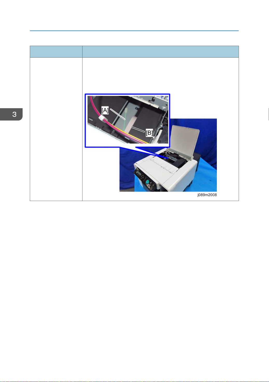
Internal Inspection Open the top cover and check whether there are any foreign materials
(particularly from when cleaning with a cotton swab [A]) inside. If there are
any foreign materials, remove them.
Make sure not to damage the FFC [B] at this time.
52
Page 55

4. Replacement and Adjustment
Before Replacing Parts
• When reassembling the machine, be sure to attach the screws to their original positions. Especially,
the blue screws are assigned to particular screw holes.
53
Page 56

4. Replacement and Adjustment
Covers
Cover Names
54
[A] Top Cover [K] Port Cover
[B] Canopy Cover [L] Left Cover
[C] Operation Panel [M] Left Lower Cover
[D] Cassette [N] Right Cover
[E] Front Cover [O] Right Lower Cover
[F] Front Right Cover [P] Rear Cover
[G] Cassette Stand [Q] Rear Top Cover
[H] Left Guide Rail Cover [R] Rear Transport Cover
Page 57

[I] Right Guide Rail Cover
[J] Front Lower Cover
Order of Cover Removal
It is very important that you understand how to remove and reinstall the covers before doing
replacement procedures. Here is a general summary of the order of removal.
Covers
Front Right Cover
1. Open the front right cover [A].
55
Page 58

4. Replacement and Adjustment
2. Disengage the latch and remove the front right cover.
Right Lower Cover
1. Remove the right lower cover [A].
56
Right Cover
1. Remove the right lower cover. (page 56 "Right Lower Cover")
Page 59

2. Open the front right cover [A], and remove all ink cartridges [B].
3. Open the top cover.
Covers
4. Remove 2 screws.
57
Page 60

4. Replacement and Adjustment
5. Remove the right cover [A].
Re-assembly
When re-attaching the right cover, check the following points.
1. Check that the harness and ink tube are secured with the tabs.
2. Check that the maintenance unit is locked.
• If the triangles are aligned tip-to-tip as shown at [A], this means the carriage is unlocked (not
ready for operation) and can be moved manually.
• Insert a screwdriver at [B], turn it counter-clockwise to rotate the lower triangle around until it
is at [C]. This locks the carriage for normal operation.
58
• Never rotate the screwdriver clockwise. It may cause a malfunction.
Page 61

3. Reattach the right cover [A].
Covers
59
Page 62

4. Replacement and Adjustment
Port Cover
1. Pressing the tab [A], remove the port cover [B].
Left Lower Cover
1. Remove the left lower cover [A].
Left Cover
1. Remove the front cover. (page 62 "Front Cover, Operation Panel Board")
2. Remove the left lower cover. (page 60 "Left Lower Cover")
3. Remove the port cover. (page 60 "Port Cover")
60
Page 63

4. Open the top cover.
5. Pull out the LAN cable [A], and remove the left cover [B].
Covers
Canopy Cover
1. Remove the right cover. (page 56 "Right Cover")
61
Page 64

4. Replacement and Adjustment
2. Remove the canopy cover [A].
Front Cover, Operation Panel Board
1. Remove the canopy cover (page 61 "Canopy Cover")
2. Remove 3 screws.
62
3. Disconnect the connector [A].
Page 65

4. Release the lock [B] and remove the FFC [C].
Covers
5. Slide the front cover [A] to the left to remove it.
63
Page 66

4. Replacement and Adjustment
6. Separate the front cover [A] and the operation panel unit [B].
7. Release the lock [A] and remove the FFC [B].
8. Remove the operation panel board cover [C].
64
9. Remove the operation panel board [A].
Page 67

Re-assembly
FFC
1. The blue band [A] must be facing up when you reconnect the FFC.
Covers
65
Page 68

4. Replacement and Adjustment
Front Cover
1. Align the tabs (3 points) on the left bottom of the front cover with the machine's frame and
slide the cover to attach it.
66
Page 69

Rear Top Cover
1. Remove the rear top cover [A].
Rear Transport Cover
Covers
1. Remove the rear top cover. (page 67 "Rear Top Cover")
2. Remove the screws of the rear transport cover.
67
Page 70

4. Replacement and Adjustment
3. Remove the rear transport cover [A].
Rear Cover, Top Cover
1. Remove the rear transport cover. (page 67 "Rear Transport Cover")
2. To enlarge the gap between the power cord cover and its door, insert a flathead
screwdriver [A].
3. Remove the door of the power cord cover [B].
68
Page 71

4. Remove the vertical motor cover [A].
5. Remove the rear cover [A].
Covers
69
Page 72

4. Replacement and Adjustment
6. Remove the bracket [A].
7. Disengage the top cover latch.
70
Page 73

[A]: Rear cover
[B]: Top cover
Top Cover Only
1. Open the top cover.
2. Remove the bracket [A].
Covers
3. Close the top cover slightly, and disengage the top cover latch.
Front Lower Cover
1. Remove the cassette.
2. Remove the right lower cover. (page 56 "Right Lower Cover")
3. Remove the left lower cover. (page 60 "Left Lower Cover")
71
Page 74

4. Replacement and Adjustment
4. Remove 2 screws of the front lower cover.
5. Disengage the two tabs on the front lower cover [A], and then remove the cover by
pulling it downward.
Right Guide Rail Cover
1. Remove the front lower cover. (page 71 "Front Lower Cover")
2. Remove the rear transport cover. (page 67 "Rear Transport Cover")
72
Page 75

Covers
3. To lift the cassette stand [B], turn the screw [A] counterclockwise until it stops by using a
flathead screwdriver.
• After the right guide rail cover is installed, turn this screw clockwise to lower the cassette stand.
Again, turn the screw until the screwdriver stops.
• If the screw stops rotating when either lifting or lowering the cassette stand, do not turn it any
further.
73
Page 76
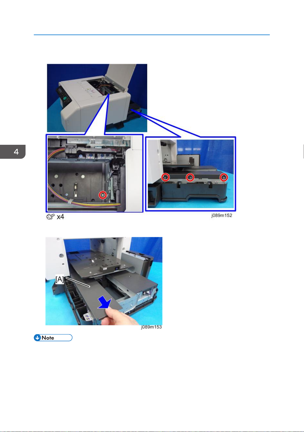
4. Replacement and Adjustment
4. Remove the screws of the right guide rail cover.
5. Remove the right guide rail cover [A].
• When attaching the right/left guide rail cover, make sure that the tabs [A] indicated by blue circles
as shown are engaged in the corresponding holes.
74
Page 77

Covers
Left Guide Rail Cover
1. Remove the front lower cover. (page 71 "Front Lower Cover")
2. Remove the rear transport cover. (page 67 "Rear Transport Cover")
3. To enlarge the gap between the power cord cover and its door, insert a flathead
screwdriver [A].
4. Remove the door of the power cord cover [B].
75
Page 78

4. Replacement and Adjustment
5. Remove the vertical motor cover [A].
6. To lift the cassette stand [B], turn the screw [A] counterclockwise until it stops by using a
flathead screwdriver.
76
• After the left guide rail cover is installed, turn this screw clockwise to lower the cassette stand.
Again, turn the screw until the screwdriver stops.
• If the screw stops rotating when either lifting or lowering the cassette stand, do not turn it any
further.
Page 79

7. Remove the screws of the left guide rail cover.
Covers
8. Remove the left guide rail cover [A].
• When attaching the right/left guide rail cover, make sure that the tabs [A] indicated by blue circles
as shown are engaged in the corresponding holes.
77
Page 80
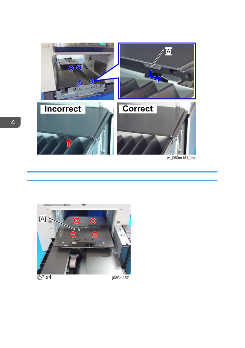
4. Replacement and Adjustment
Cassette Stand
1. Remove the rear transport cover. (page 67 "Rear Transport Cover")
2. Remove the 4 screws to turn over the cassette stand [A].
78
Page 81

3. Release the cable clamp [A], and disconnect the connector [B] to remove the cassette
stand.
4. There are 4 caps [B] attached to the cassette carriage [A], which has had the cassette
stand removed. Use the screws removed in Step 2 to fix the caps.
Covers
• Do not remove caps [A] or spacers [B].
• Each cap and spacer is used to adjust the height at each of the 4 points ; so they are not
interchangeable. If any caps or spacers become loose when removing the cassette stand,
make sure to return them to their original position.
79
Page 82

4. Replacement and Adjustment
80
Page 83

Ink Collector Unit
Ink Collector Unit
Before You Begin
Never remove the ink collector unit unless it requires replacement. A message will appear and tell you
that the ink collector unit needs to be replaced.
• You will need a self-sealing plastic bag to hold the ink collector unit.
• When you dispose of the used ink collector unit always obey the local laws and regulations
regarding the disposal of such items.
At any time you can determine if the ink collector unit needs to be replaced.
• Never attempt to clean and re-use an ink collector unit.
• Attach the ink collector unit that is marked "J089" under the case handle. Attaching a different ink
collector unit will cause an error to occur.
81
Page 84
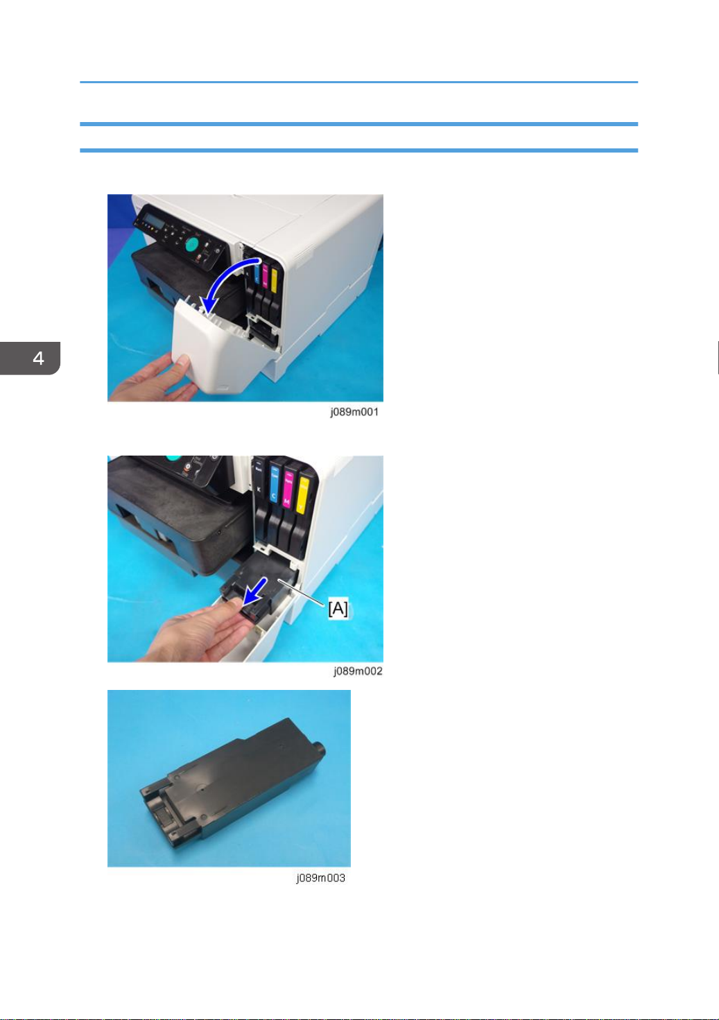
4. Replacement and Adjustment
Replace the Ink Collector Unit
1. Open the front right cover.
2. Pull the ink collector unit [A] out.
82
Page 85

• The ink collector is completely enclosed to prevent leakage. If you are replacing the ink
collector unit, insert a new one.
3. Push in the new ink collector [A] until you hear it snap and lock in place.
4. Close the front right cover.
Ink Collector Unit
• The ink collector unit has an internal ID chip that automatically resets the counter for the ink
collector unit. No SP adjustment is required.
5. Discard the used ink collector unit.
• Obey the local laws and regulations regarding disposal of items like the full ink collector unit.
• Never attempt to open and clean a full ink collector unit and use it again.
83
Page 86

4. Replacement and Adjustment
Maintenance Unit, Right Ink Sump
Maintenance Unit
• The bottom edges of the maintenance unit are covered with ink.
• Avoid touching the bottom of the maintenance unit.
1. Open the front right cover and pull out the ink collector unit [A].
84
2. Open the top cover.
3. Remove the right cover. (page 56 "Right Cover")
4. Insert the tip of a screwdriver into the hole [A] and turn it counter-clockwise to rotate the
lower triangle [B] up to the other triangle until they are aligned.
When the triangles are aligned, the carriage is unlocked.
Page 87

Maintenance Unit, Right Ink Sump
5. Push the carriage [A] to the center of the machine.
6. The maintenance unit has ink on it, so put a sheet of paper [A] down to avoid staining.
7. Release the lock [A], and then remove the injector.
Be careful when removing the injector, because ink may drip from its head.
8. Remove the maintenance unit [A] and lay it on paper.
The bottom of the unit is covered with ink. Avoid touching the bottom of the unit.
85
Page 88

4. Replacement and Adjustment
• After re-installing the maintenance unit, print the Nozzle Check Pattern and perform print head
Right Ink Sump
1. Remove the maintenance unit. (page 84 "Maintenance Unit")
2. Remove the ink supply unit. (page 136 "Ink Supply Unit")
86
cleaning if necessary.
Page 89

3. Remove the right ink sump.
Maintenance Unit, Right Ink Sump
• After re-installing the maintenance unit, print the Nozzle Check Pattern and perform print
head cleaning if necessary.
87
Page 90

4. Replacement and Adjustment
Encoders
Vertical Encoder Wheel
1. Remove the cassette stand. (page 78 "Cassette Stand")
2. Remove the left guide rail cover. (page 75 "Left Guide Rail Cover")
3. Remove the belt engaging bracket [A].
4. Remove the spring [A].
88
Page 91

5. Remove the screw on the left side of the machine.
6. Remove the tension pulley unit. [A]
Encoders
7. Remove the power cord cover. [A]
89
Page 92

4. Replacement and Adjustment
8. Remove an E-ring. [A]
9. Disconnect the connector and remove the bracket [A].
10. Loosen the screw to loosen the belt tension.
90
Page 93

11. Remove the vertical encoder unit [A].
12. Remove the bearing [A], shaft [B], and the vertical encoder wheel [C].
Encoders
• Handle the vertical encoder wheel carefully. Never touch the encoder disc [A].
91
Page 94

4. Replacement and Adjustment
Horizontal Encoder Strip
1. Remove the left cover. (page 60 "Left Cover")
2. Unlock the carriage [A] and push it to the center. (page 84 "Maintenance Unit")
3. Cover the guide rail with paper to prevent the grease on the rail from staining the
encoder strip.
92
4. Insert a flathead screwdriver [A] under the carriage.
The carriage is slightly lifted and the encoder strip is freed.
Page 95

Encoders
5. While bending the leaf spring [A] inward to loosen the tension of the encoder strip [B],
disengage the hook at the left end [C] and remove the strip.
• After removing the horizontal encoder strip, use the prepared plastic encoder strip to clean the
horizontal encoder sensor. For details, see "page 160 "Horizontal Encoder Sensor Cleaning "".
93
Page 96

4. Replacement and Adjustment
Reinstallation
• When replacing the horizontal encoder strip with a new one:
• Do not try to clean and reuse the horizontal encoder strip (because the slit is fine, dirt cannot
be completely wiped off).
• Do not fold, bend, or strongly warp the horizontal encoder strip. Also, do not use an encoder
strip with a deformed slit.
(Images of unacceptable examples)
[A]: A horizontal encoder strip with a deformed slit.
[B]: A horizontal encoder strip folded at a sharp angle.
• The new horizontal encoder strip is covered with protective film to prevent the strip from
bending and contamination. Do not peel off the protective film until after attaching the
strip. Also, do not touch the strip after peeling off the protective film.
94
Page 97

Encoders
[A]: Horizontal encoder strip without protective film
[B]: Horizontal encoder strip with protective film
• Do not place the horizontal encoder strip vertically. (This may cause the strip to deform.)
• When carrying out this work, hold both edges of the horizontal encoder strip, and do not
touch the slit.
Attachment Procedure
1. Cover the guide rail with paper to prevent the grease on it from staining the horizontal
encoder strip.
95
Page 98

4. Replacement and Adjustment
2. Attach the horizontal encoder strip onto the leaf spring [B] hook so that the notch of the
horizontal encoder strip [A] is on top.
• Check that the protective film surface of the sheet [A] is facing the guiderail [B].
96
Page 99

Encoders
3. Pass the strip through the gap [A] of the sensor inside the carriage, and then, attach the
other side of the horizontal encoder strip onto the other hook [B].
4. Move the carriage [A] to the right side, hold the tip [B] of the protective film on the left
side of the horizontal encoder strip, and then peel off the protective film.
97
Page 100

4. Replacement and Adjustment
5. Move the carriage [A] to the left side, hold the tip [B] of the protective film on the right
side of the horizontal encoder strip, and then peel off the protective film.
6. Remove the paper that was placed in Step 1.
• If dirt such as grease or ink is affixed to the attached horizontal encoder strip, or it is
scratched, damaged or bent, replace with a new horizontal encoder strip.
98
 Loading...