

Ricoh Gim-MF1a, Gim-MF1b, M173, M172 Field Service Manual

Model Gim-MF1a/b
Machine Code:
M172/M173
Field Service Manual
September, 2014


Important Safety Notices
Important Safety Notices
Prevention of Physical Injury
1. Before disassembling or assembling parts of the main machine and peripherals, make sure that the
power cord of the main machine is unplugged.
2. The wall outlet should be near the machine and easily accessible.
3. Note that some components of the machine and the paper tray unit are supplied with electrical
voltage even if the main power switch is turned off.
If any adjustment or operation check has to be made with exterior covers off or open while the
4.
main switch is turned on, keep hands away from electrified or mechanically driven components.
5. The inside and the metal parts of the fusing unit become extremely hot while the machine is
operating. Be careful to avoid touching those components with your bare hands.
• To prevent a fire or explosion, keep the machine away from flammable liquids, gases, and
aerosols.
Health Safety Conditions
1. Toner and developer is non-toxic, but if you get either of them in your eyes by accident, it may
cause temporary eye discomfort. Immediately wash eyes with plenty of water. If unsuccessful, get
medical attention.
2. This machine, which uses a high voltage power source, can generate ozone gas. High ozone
density is harmful to human health. Therefore, the machine must be installed in a well-ventilated
room.
Observance of Electrical Safety Standards
1. This machine and its peripherals must be serviced by a customer service representative who has
completed the training course on those models.
2. The NVRAM on the system control board has a lithium battery which can explode if replaced
incorrectly. Replace the NVRAM only with an identical one. The manufacturer recommends
replacing the entire NVRAM. Do not recharge or burn this battery. Used NVRAM must be handled
in accordance with local regulations.
1

Handling Toner
• Work carefully when removing paper jams or replacing toner bottles or cartridges to avoid spilling
toner on clothing or the hands.
• If toner is inhaled, immediately gargle with large amounts of cold water and move to a well
ventilated location. If there are signs of irritation or other problems, seek medical attention.
• If toner gets on the skin, wash immediately with soap and cold running water.
If toner gets into the eyes, flush the eyes with cold running water or eye wash. If there are signs of
•
irritation or other problems, seek medical attention.
• If toner is swallowed, drink a large amount of cold water to dilute the ingested toner. If there are
signs of any problem, seek medical attention.
• If toner spills on clothing, wash the affected area immediately with soap and cold water. Never use
hot water! Hot water can cause toner to set and permanently stain fabric.
• Always store toner and developer supplies such as toner and developer packages, cartridges, and
bottles (including used toner and empty bottles and cartridges) out of the reach of children.
• Always store fresh toner supplies or empty bottles or cartridges in a cool, dry location that is not
exposed to direct sunlight.
• Do not use a vacuum cleaner to remove spilled toner (including used toner). Vacuumed toner may
cause a fire or explosion due to sparks or electrical contact inside the cleaner. However, it is
possible to use a cleaner designed to be dust explosion-proof. If toner is spilled over the floor,
sweep up spilled toner slowly and clean up any remaining toner with a wet cloth.
Safety and Ecological Notes for Disposal
1. Do not incinerate toner bottles or used toner. Toner dust may ignite suddenly when exposed to an
open flame.
2. Dispose of used toner, the maintenance unit which includes developer or the organic
photoconductor in accordance with local regulations. (These are non-toxic supplies.)
3. Dispose of replaced parts in accordance with local regulations.
When keeping used lithium batteries in order to dispose of them later, do not put more than 100
4.
batteries per sealed box. Storing larger numbers or not sealing them apart may lead to chemical
reactions and heat build-up.
2
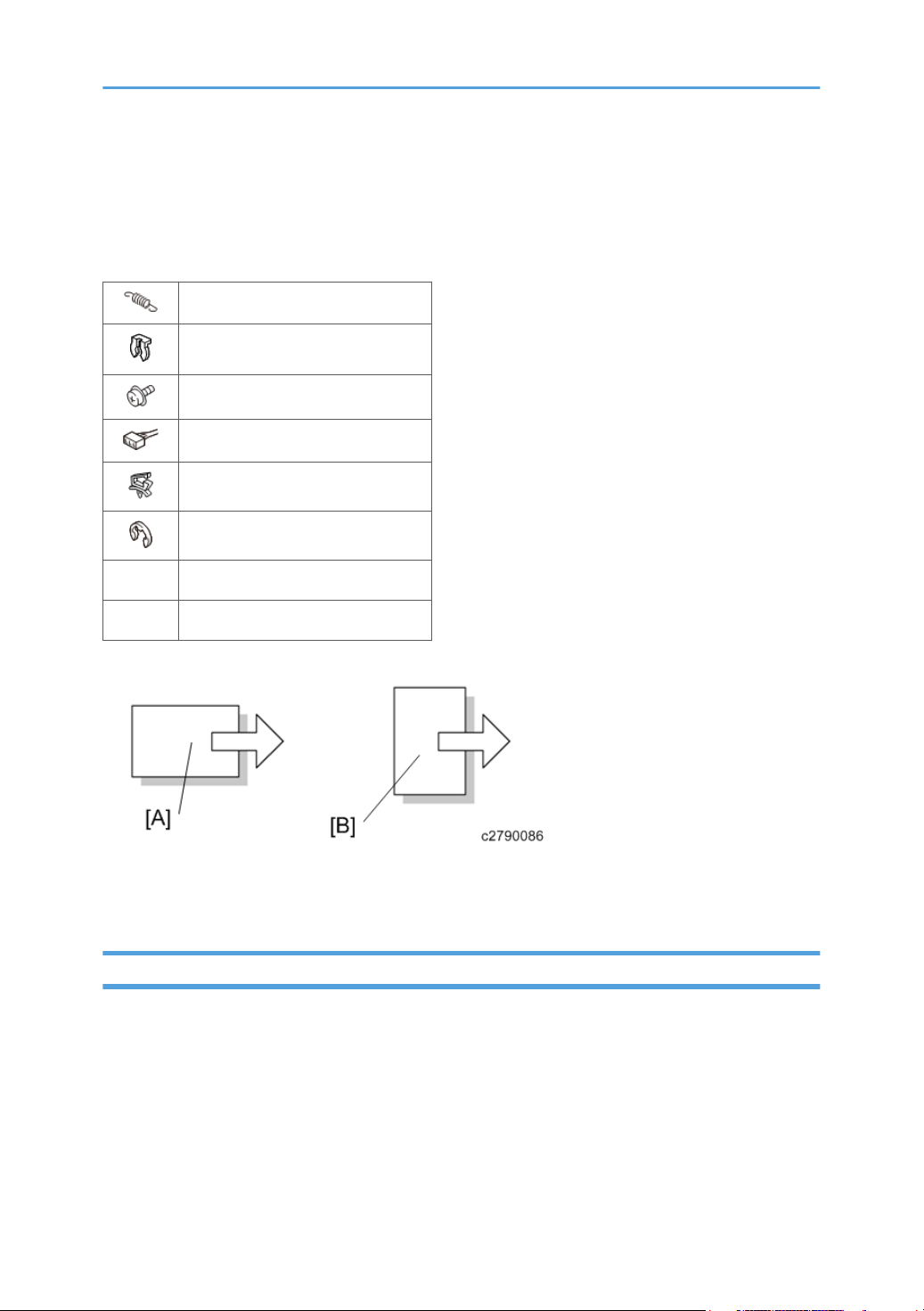
Symbols, Abbreviations and Trademarks
This manual uses several symbols and abbreviations. The meaning of those symbols and abbreviations
are as follows:
Spring
Clip ring
Screw
Connector
Clamp
E-ring
SEF Short Edge Feed
LEF Long Edge Feed
[A] Short Edge Feed (SEF)
[B] Long Edge Feed (LEF)
Trademarks
Adobe, Acrobat, PostScript, PostScript 3, and Reader are either registered trademarks or trademarks of
Adobe Systems Incorporated in the United States and/or other countries.
Java is a registered trademark of Oracle and/or its affiliates.
JAWS® is a registered trademark of Freedom Scientific, Inc., St. Petersburg, Florida and/or other
countries.
Macintosh, Mac OS, and TrueType are trademarks of Apple Inc., registered in the U.S. and other
countries.
3

Microsoft, Windows, Windows Server, Windows Vista, and Internet Explorer are either registered
trademarks or trademarks of Microsoft Corp. in the United States and/or other countries.
OpenLDAP is a registered trademark of the OpenLDAP Foundation.
UNIX is a registered trademark of The Open Group.
UPnP is a trademark of UPnP Implementers Corporation.
The proper name of Internet Explorer 8 is Windows® Internet Explorer® 8.
The proper names of the Windows operating systems are as follows:
• The product names of Windows XP are as follows:
• Microsoft® Windows® XP Professional
Microsoft® Windows® XP Home Edition
•
• Microsoft® Windows® XP Media Center Edition
• Microsoft® Windows® XP Tablet PC Edition
• The product names of Windows Vista are as follows:
• Microsoft® Windows Vista® Ultimate
• Microsoft® Windows Vista® Business
• Microsoft® Windows Vista® Home Premium
• Microsoft® Windows Vista® Home Basic
• Microsoft® Windows Vista® Enterprise
• The product names of Windows 7 are as follows:
• Microsoft® Windows® 7 Home Premium
• Microsoft® Windows® 7 Professional
• Microsoft® Windows® 7 Ultimate
• Microsoft® Windows® 7 Enterprise
• The product names of Windows 8 are as follows:
• Microsoft® Windows® 8
• Microsoft® Windows® 8 Pro
• Microsoft® Windows® 8 Enterprise
• The product names of Windows 8.1 are as follows:
• Microsoft® Windows® 8.1
• Microsoft® Windows® 8.1 Pro
• Microsoft® Windows® 8.1 Enterprise
• The product names of Windows Server 2003 are as follows:
• Microsoft® Windows Server® 2003 Standard Edition
4

• Microsoft® Windows Server® 2003 Enterprise Edition
• The product names of Windows Server 2003 R2 are as follows:
• Microsoft® Windows Server® 2003 R2 Standard Edition
Microsoft® Windows Server® 2003 R2 Enterprise Edition
•
• The product names of Windows Server 2008 are as follows:
• Microsoft® Windows Server® 2008 Standard
• Microsoft® Windows Server® 2008 Enterprise
• The product names of Windows Server 2008 R2 are as follows:
• Microsoft® Windows Server® 2008 R2 Standard
• Microsoft® Windows Server® 2008 R2 Enterprise
• The product names of Windows Server 2012 are as follows:
• Microsoft® Windows Server® 2012 Foundation
• Microsoft® Windows Server® 2012 Essentials
• Microsoft® Windows Server® 2012 Standard
• The product names of Windows Server 2012 R2 are as follows:
• Microsoft® Windows Server® 2012 R2 Foundation
• Microsoft® Windows Server® 2012 R2 Essentials
• Microsoft® Windows Server® 2012 R2 Standard
Other product names used herein are for identification purposes only and might be trademarks of their
respective companies. We disclaim any and all rights to those marks.
Microsoft product screen shots reprinted with permission from Microsoft Corporation.
5

TABLE OF CONTENTS
Important Safety Notices................................................................................................................................... 1
Important Safety Notices............................................................................................................................... 1
Prevention of Physical Injury................................................................................................................. 1
Health Safety Conditions...................................................................................................................... 1
Observance of Electrical Safety Standards.........................................................................................1
Handling Toner...................................................................................................................................... 2
Safety and Ecological Notes for Disposal................................................................................................... 2
Symbols, Abbreviations and Trademarks.........................................................................................................3
Trademarks..................................................................................................................................................... 3
1. Product Information
Product Overview.............................................................................................................................................13
Component Layout.......................................................................................................................................13
Paper Path.................................................................................................................................................... 14
Drive Layout..................................................................................................................................................15
Machine Codes and Peripheral Configuration............................................................................................. 16
Specifications....................................................................................................................................................18
2. Installation
Installation Requirements................................................................................................................................. 19
Environment..................................................................................................................................................19
Machine Space Requirements....................................................................................................................20
Machine Dimensions................................................................................................................................... 20
Power Requirements.................................................................................................................................... 20
Main Machine Installation...............................................................................................................................22
Accessory Check..........................................................................................................................................22
Instructions for the Customers......................................................................................................................23
Moving the Machine................................................................................................................................... 23
Security Settings........................................................................................................................................... 24
Changing an Administrator's Password.............................................................................................24
Configuring SSL/TLS...........................................................................................................................25
Settings for @Remote Service..........................................................................................................................26
Check points before making @Remote settings.........................................................................................26
Execute the @Remote Settings.................................................................................................................... 26
6

3. Preventive Maintenance
Preventive Maintenance Tables...................................................................................................................... 31
Image Quality Standards................................................................................................................................ 32
Paper Transfer Quality Standards.................................................................................................................. 34
4. Replacement and Adjustment
General Cautions.............................................................................................................................................35
Notes on the Main Power Switch...............................................................................................................35
Characteristics of the Push Switch (DC Switch).................................................................................35
Shutdown Method...............................................................................................................................36
Forced Shutdown................................................................................................................................ 36
Exterior Covers................................................................................................................................................. 37
Front Cover...................................................................................................................................................37
Left Cover......................................................................................................................................................39
Right Cover...................................................................................................................................................40
Rear Cover, Rear Lower Cover...................................................................................................................41
Upper Cover................................................................................................................................................ 42
Operation Panel...........................................................................................................................................43
LED Optics........................................................................................................................................................ 45
LED Unit........................................................................................................................................................ 45
How to Re-engage Disengaged Springs.......................................................................................... 49
PCDU.................................................................................................................................................................53
PCDU............................................................................................................................................................ 53
Toner Cartridge................................................................................................................................................ 54
Toner Cartridge............................................................................................................................................54
Image Transfer..................................................................................................................................................55
Image Transfer Roller...................................................................................................................................55
Drive Unit.......................................................................................................................................................... 56
Main Motor..................................................................................................................................................
Toner Supply Clutch.................................................................................................................................... 56
Registration Clutch....................................................................................................................................... 57
Paper Feed Clutch........................................................................................................................................58
Drive Unit......................................................................................................................................................58
Gear Unit......................................................................................................................................................59
56
7

By-pass Feed Clutch.................................................................................................................................... 61
Relay Clutch................................................................................................................................................. 61
By-pass Bottom Plate Clutch........................................................................................................................62
Duplex Clutch...............................................................................................................................................62
Junction Gate Solenoid............................................................................................................................... 63
Fusing................................................................................................................................................................ 64
Fusing Unit.................................................................................................................................................... 64
Upper Fusing Unit, Lower Fusing Unit........................................................................................................ 65
Fusing Pressure Roller, Cleaning Roller......................................................................................................66
Fusing Lamp, Hot Roller...............................................................................................................................67
Thermostat.................................................................................................................................................... 69
Thermistor..................................................................................................................................................... 70
Hot Roller Stripper....................................................................................................................................... 73
Paper Feed........................................................................................................................................................74
Paper Feed Tray...........................................................................................................................................74
Paper Feed Roller........................................................................................................................................ 74
Friction Pad...................................................................................................................................................75
Paper End Sensor.........................................................................................................................................75
By-pass Feed Unit........................................................................................................................................ 76
By-pass Feed Roller..................................................................................................................................... 77
By-pass Friction Pad.................................................................................................................................... 79
By-pass Paper End Sensor.......................................................................................................................... 80
By-pass Bottom Plate HP Sensor.................................................................................................................81
Paper Size Detection Switch....................................................................................................................... 81
Paper Transport................................................................................................................................................ 83
Exit / Switchback Sensor............................................................................................................................ 83
Duplex Entrance Sensor.............................................................................................................................. 83
Exit / Switchback Roller, Duplex Exit Gear...............................................................................................84
Registration Roller (Driven)..........................................................................................................................86
Registration Roller (Drive)............................................................................................................................88
Registration Sensor...................................................................................................................................... 88
Electrical Components..................................................................................................................................... 90
Controller Box.............................................................................................................................................. 90
8

FCU............................................................................................................................................................... 91
Interface Cover............................................................................................................................................ 91
Speaker........................................................................................................................................................ 92
PSU................................................................................................................................................................92
Controller Board.......................................................................................................................................... 94
BCU...............................................................................................................................................................95
EEPROM on the BCU.................................................................................................................................. 97
Toner End Sensor.........................................................................................................................................97
HVPS............................................................................................................................................................. 98
HVPS with Bracket....................................................................................................................................... 98
Fusing Fan.....................................................................................................................................................99
PCDU Cooling Fan...................................................................................................................................... 99
PSU Cooling Fan....................................................................................................................................... 100
DC Switch.................................................................................................................................................. 100
Front Door Interlock Switch...................................................................................................................... 101
Rear Door Interlock Switch.......................................................................................................................102
Temp Humid Sensor.................................................................................................................................. 102
Rear Cover Switch.....................................................................................................................................102
ADF................................................................................................................................................................. 104
ADF Unit..................................................................................................................................................... 104
ADF Front Cover........................................................................................................................................106
ADF Rear Cover........................................................................................................................................ 107
ADF Paper Feed Cover, ADF Original Sensor Feeler............................................................................108
ADF Original Tray..................................................................................................................................... 108
ADF Original Feed Unit............................................................................................................................ 109
ADF Harness Guide, ADF Original Set Sensor, ADF Paper Feed Cover Open/Closed Sensor.......110
ADF Transport Motor, ADF Gear Unit.....................................................................................................110
ADF Transport Unit.................................................................................................................................... 111
ADF Separation Roller, ADF Separation Roller Cover...........................................................................112
ADF Paper Exit Guide............................................................................................................................... 113
ADF Pre-Scanning Roller, ADF Pre-Scanning Shaft............................................................................... 113
Scanner...........................................................................................................................................................115
Scanner Unit (with ADF)........................................................................................................................... 115
9

Scanner (unit only).................................................................................................................................... 118
5. System Maintenance
Service Program Mode.................................................................................................................................121
SP Tables....................................................................................................................................................121
Enabling and Disabling Service Program Mode....................................................................................121
Entering SP Mode.............................................................................................................................121
Exiting SP Mode............................................................................................................................... 122
Types of SP Modes....................................................................................................................................122
Updating the Firmware..................................................................................................................................124
Overview....................................................................................................................................................124
Environmental Requirements............................................................................................................124
Update Precautions.......................................................................................................................... 124
Items Required for Updating the Firmware.....................................................................................125
Update Procedure............................................................................................................................ 125
Update Error (Recovery Mode)...................................................................................................... 129
Address Book Backup/Restore.................................................................................................................... 132
Back Up/Restore.......................................................................................................................................132
Debug Log......................................................................................................................................................133
Overview....................................................................................................................................................133
Operational procedure (USB connection)..............................................................................................134
Operational procedure (TCP/IP connection)......................................................................................... 135
Operational procedure (USB flash drive)............................................................................................... 135
6. Troubleshooting
Self-Diagnostic Mode................................................................................................................................... 137
Self-Diagnostic Mode at Power On.........................................................................................................137
Service Call.................................................................................................................................................... 138
Summary.................................................................................................................................................... 138
When a Level “D” SC code occurs.................................................................................................138
SC100 (Scanning).................................................................................................................................... 139
SC200 (LED Optics)................................................................................................................................. 140
SC300 (Image Processing – 1)............................................................................................................... 142
SC400 (Image Processing – 2)............................................................................................................... 144
SC500 (Paper Feed and Fusing)............................................................................................................. 145
10

SC600 (Device Communication).............................................................................................................153
SC700 (Peripherals)................................................................................................................................. 158
SC800 (Controller)................................................................................................................................... 158
SC900 (Others).........................................................................................................................................165
Jam Detection.................................................................................................................................................169
Jam Displays.............................................................................................................................................. 169
Removing Jammed Paper......................................................................................................................... 169
Sensor Position Layout.............................................................................................................................. 170
Jam Codes and Position Codes................................................................................................................170
ADF.................................................................................................................................................... 171
Main Machine.................................................................................................................................. 171
Optional Bank...................................................................................................................................172
Troubleshooting............................................................................................................................................. 173
Test Sheet Printing......................................................................................................................................173
Image Position Adjustment........................................................................................................................173
Registration Adjustment.............................................................................................................................174
Print Area...........................................................................................................................................174
Adjustment Reference Values...........................................................................................................175
Adjustment Procedure.......................................................................................................................175
Scanner, ADF Image Adjustment............................................................................................................. 175
Scanner Image Adjustment.............................................................................................................. 175
ADF Image Adjustment.....................................................................................................................177
Problem at Regular Intervals.....................................................................................................................178
When Vertical Banding is Generated.............................................................................................179
When Black Spots are Generated on the Print Image.................................................................. 179
Paper Feed (Skew)....................................................................................................................................180
Recycled or Thin Paper Is Severely Curled after Printing.......................................................................181
7. Energy Save
Energy Save................................................................................................................................................... 183
Energy Saver Modes................................................................................................................................ 183
Sleep Mode Setting..........................................................................................................................183
Return to Stand-by Mode.................................................................................................................184
Recommendation..............................................................................................................................184
11

Paper Save.....................................................................................................................................................186
Effectiveness of Duplex/Combine Function............................................................................................ 186
1. Duplex:..........................................................................................................................................186
2. Combine mode:............................................................................................................................186
3. Duplex + Combine:...................................................................................................................... 187
Recommendation..............................................................................................................................187
12

1. Product Information
Product Overview
Component Layout
1. Exit / Switchback unit
2. Fusing unit
3. PCDU
LED head
4.
5. Toner cartridge
6. By-pass feed tray
7. Paper feed unit
8. Duplex paper path
13
1. Product Information
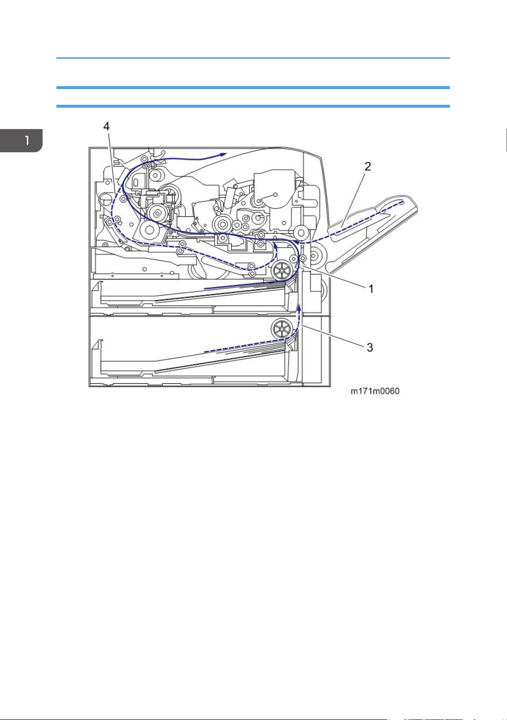
Paper Path
14
1. Main machine paper feed path
2. By-pass paper feed path
3. Optional tray paper feed path
Duplex paper feed path
4.

Drive Layout
Product Overview
1. Exit / Switchback gear
2. Fusing drive gear
3. Drum gear
4.
Registration clutch
5. Toner supply clutch
6. By-pass feed clutch
7. By-pass bottom plate clutch
8. Relay clutch
9. Paper feed clutch
10. Main motor
11. Duplex clutch
15
1. Product Information
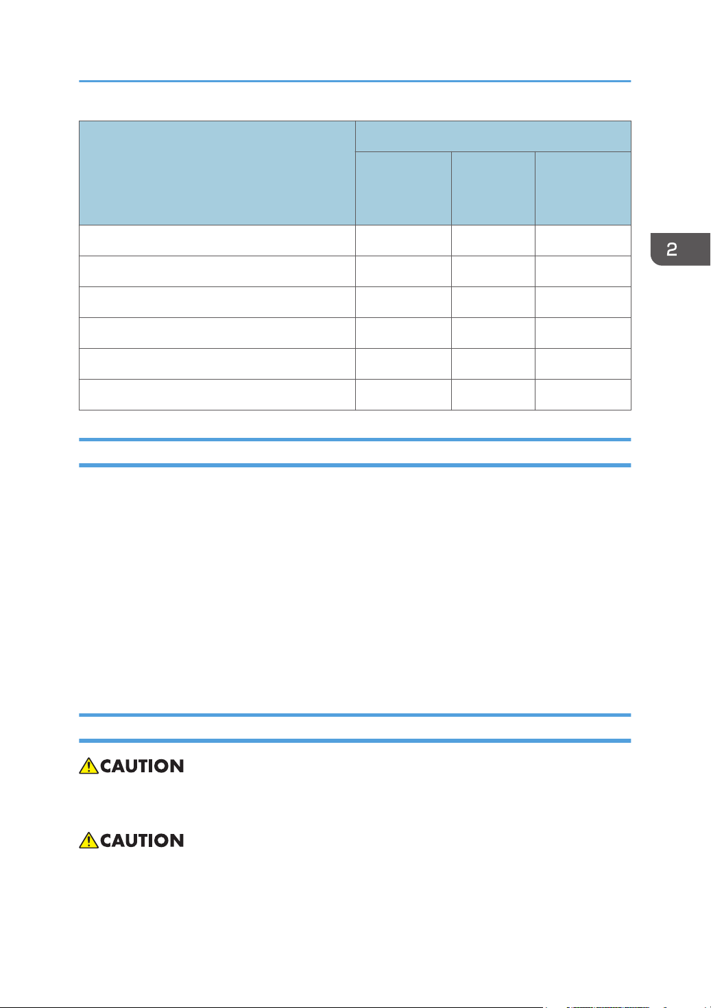
Machine Codes and Peripheral Configuration
Main Frame
Item Machine Code Remarks
M172
M173
External Options
M172-17 (NA)
M172-27 (EU/AP)
M173-17 (NA)
M173-27 (EU/AP)
M173-21 (CHN)
NEW
NEW
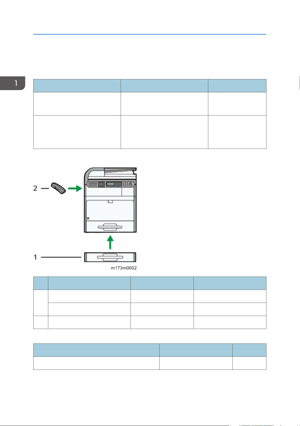
No. Item Machine Code Remarks
1 Paper Feed Unit PB1070 M440-17 NEW
2 Handset HS1010 M444-38 (NA) NEW
Internal Options
IEEE802.11 Interface Unit Type P6 M455-01 -
16
Paper Feed Unit PB1060 M441-17 NEW
Item Machine Code Remarks

Machine Codes and Peripheral Configuration
Consumables
Item Machine Code Remarks Yield
Print Cartridge SP 4500A M902-17 NEW
Print Cartridge SP 4500E M902-27 NEW
Print Cartridge SP 4500S M902-20 NEW
Print Cartridge SP 4500C M902-21 NEW
Print Cartridge SP 4500LA M903-17 NEW
Print Cartridge SP 4500LE M903-27 NEW
Print Cartridge SP 4500LS M903-20 NEW
Print Cartridge SP 4500LC M903-21 NEW
Photo Conductor Unit SP 4500 M906-17(NA/EU/
AP)
NEW
M906-21 (CHN)
Maintenance Kit SP 3600 M909-17 (NA)
M909-27 (EU/AP/
NEW -
CHN)
6,000 pages
(ISO)
3,000 pages
(ISO)
20,000 pages
(3P/J)
• (ISO): The number of printable pages is based on pages that are compliant with ISO/IEC 19752
with the image density set as the factory default. ISO/IEC 19752 is an international standard for
measurement of printable pages, set by the International Organization for Standardization.
• (6%, 3P/J): A4/Letter 6% test chart, 3 pages/job
• (3P/J): A4/Letter, 3 pages/job
17

1. Product Information
Specifications
See "Appendices" for the following information:
• General Specifications
• Supported Paper Sizes
Software Accessories
•
• Optional Equipment
18

2. Installation
Installation Requirements
Environment
1. Temperature Range: 10°C to 32°C (50°F to 89.6°F)
2. Humidity Range: 15% to 80% RH
3. Ambient Illumination: Less than 1,500 lux (do not expose to direct sunlight)
4.
Ventilation: 3 times/hr/person
5. Do not install the machine at locations over 2,000 m (6,562 ft.) above sea level.
19
2. Installation
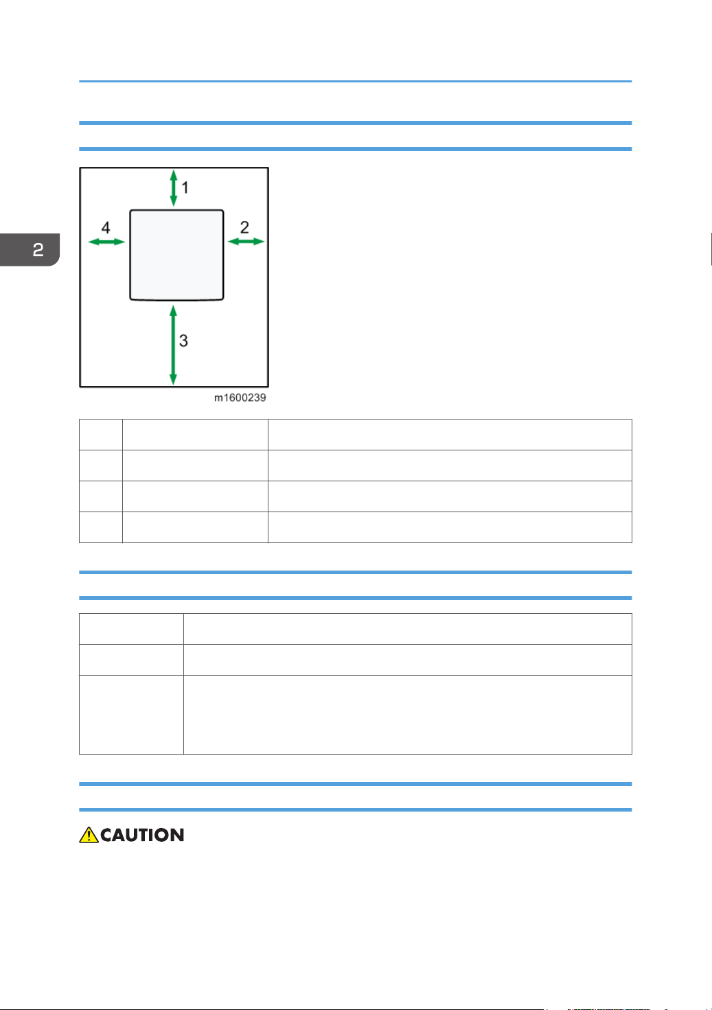
Machine Space Requirements
1 Rear Over 20 cm (7.9 inches)
2 Right Over 10 cm (3.9 inches)
3 Front Over 35 cm (13.8 inches)
4 Left Over 10 cm (3.9 inches)
Machine Dimensions
Width 400 mm (15.7 inches)
Depth 392 mm (15.4 inches)
406 mm (16.0 inches)
Height
• With Paper Feed Unit PB1060 attached: 501 mm (19.7 inches):
• With Paper Feed Unit PB1070 attached: 531 mm (20.9 inches):
Power Requirements
• Make sure the plug is firmly inserted in the outlet.
• Avoid multi-wiring.
20
• Be sure to ground the machine.

• Never place anything on the power cord.
1. Input voltage level:
Destination Power supply voltage Frequency Rated current consumption
NA 120 V to 127 V 60 Hz More than 10 A
EU/AP/CHN 220 V to 240V 50 Hz/60 Hz 5.3 A
2. Permissible voltage fluctuation:
Destination For printing images For operating
NA +8.66 / -10% +8.66 / -15%
EU/AP/CHN ±10% ±15%
Installation Requirements
21

2. Installation
Main Machine Installation
• The M172/M173 is for installation by users.
Accessory Check
Q’ty
Description
Power Supply Cord 1 1 1
Modular Cord:NA 1 - -
Modular Cord:6pin-6pin - 1 -
Sheet – Security Password 1 1 1
Sheet – SEC_NOT_GW_C 1 1 1
Sheet – EULA(End User License Agreement) 1 1 1
Cleaner – Lens:LED Head 1 1 1
Sheet – PCDU End 4Line 1 1 1
CD-ROM – Page Manager 1 1 1
Guarantee 1 1 -
CD-ROM – Driver 1 - 1
-17
(M172/
M173)
-21
(M172 only)
-27
(M172/
M173)
22
CD-ROM – OI 1 - 1
CD-ROM – Driver/OI - 1 -
Manual – User Guide 1 1 -
Manual – Initial Guide for FAX 1 - -
Manual – Read_This_First 1 1 -
Sheet – Quick installation Guide 1 1 -
Main Machine Installation
Q’ty
Description
User Registration Sheet 1 - -
Sheet – Helpdesk 1 - -
Sheet – China Energy - 1 -
Sheet – Accesorry:Safety - - 1
EMC - Traceability - - 1
Sheet – Caution Chart - - 1
-17
(M172/
M173)
-21
(M172 only)
(M172/
M173)
Instructions for the Customers
Provide instructions on the following matters to customers. For detailed procedures, see the user
manuals.
• Operating the printer function
• Installing consumables and loading paper
-27
•
Operating the main power switch
• Removing jammed paper
• Providing precautions on use
• Connecting to computers (such as configuring the port setting)
• Giving a brief outline of the tabs in the drivers
Moving the Machine
• It is dangerous to handle the power cord plug with wet hands. Doing so could result in electric
shock.
• Unplug the power cord from the wall outlet before you move the machine. While moving the
machine, take care that the power cord is not damaged under the machine. Failing to take these
precautions could result in fire or electric shock.
23

2. Installation
• When disconnecting the power cord from the wall outlet, always pull the plug, not the cord. Pulling
the cord can damage the power cord. Use of damaged power cords could result in fire or electric
shock.
• The machine weighs approximately 19 kg (41.9 lb.). When moving the machine, use the inset
grips on both sides, and lift slowly in pairs. The machine will break or cause injury if dropped.
• Be careful when moving the machine. Take the following precautions:
• Close all covers and trays, including the front cover and by-pass tray.
• If optional paper feed units are attached, remove them from the machine and move them
separately.
Keep the machine level and carry it carefully, taking care not to jolt or tip it. Rough handling
•
may cause a malfunction or damage the memory, resulting in loss of stored files.
1. Be sure to check the following:
The main power switch is turned off.
The power cord is unplugged from the wall outlet.
The interface cable is unplugged from the machine.
2. If any external options are attached, remove them.
3. Lift the machine using the inset grips on both sides of the machine, and then move it
horizontally to the place where you want to use it.
4. If you removed options, reattach them.
• Be sure to move the machine horizontally. To prevent toner from scattering, move the machine
slowly.
Security Settings
Changing an Administrator's Password
This section explains how to change the administrator’s password for Web Image Monitor.
• You will be prompted to enter the password when logging in to the printer. No password is set by
default.
24

Main Machine Installation
• We strongly recommend you to change the factory default password immediately to prevent
information leakage and unauthorized operations by others.
1. Log in as the administrator from Web Image Monitor.
2. Click [Configuration].
3. Click [Administrator Authentication] under "Administrator Tools".
4. Enter the login password in [New Password].
5. Re-enter the login password in [Confirm Password], and then click [OK].
6. Click [OK].
• For details, see the user manual "Security Guide".
Configuring SSL/TLS
To prevent unauthorized viewing, analysis or modification of the data during its transmission, enable
SSL/TLS as required.
• For details, see the user manual "Security Guide".
25

2. Installation
Settings for @Remote Service
• Prepare and check the following check points before you visit the customer site. For details, ask the
@Remote key person.
Check points before making @Remote settings
1. The setting of SP5816-201 in the mainframe must be "0".
2. Print the SMC with SP5-990-002 and then check if a device ID2 (SP5811-003) must be
correctly programmed.
• 6 spaces must be put between the 3-digit prefix and the following 8-digit number (e.g.
xxx______xxxxxxxx).
3. The following settings must be correctly programmed.
4. If a proxy server is available, configure the following SP settings.
• Use Proxy (SP5816-062) Set to "1: Enable".
Proxy server IP address (SP5816-063)
•
• Proxy server Port number (SP5816-064)
• Proxy User ID (SP5816-065)
• Proxy Password (SP5816-066)
5. Reboot the machine.
6. Get a Request Number.
Execute the @Remote Settings
1. Enter the SP mode.
2. Input the Request number which you have obtained from @Remote Center GUI, and then
enter [OK] with SP5816-202.
3. Confirm the Request number, and then click [EXECUTE] with SP5816-203.
4. Check the confirmation result with SP5816-204.
Value Meaning Solution/ Workaround
0 Succeeded -
26
1 Request number error Check the request number again.

Settings for @Remote Service
Value Meaning Solution/ Workaround
Communication error (proxy
3
enabled)
Communication error (proxy
4
disabled)
Proxy error (Illegal user name or
5
password)
Check the network condition.
Check the network condition.
Check Proxy user name and password.
6 Communication error Check the network condition.
8 Other error See "SP5816-208 Error Codes" below this.
Request number confirmation
9
executing
Processing… Please wait.
20 Dial-up authentication error
21 Answer tone detection error
22 Carrier detection error
23 Invalid setting value (modem)
These errors occur only in the modems that
support @Remote.
24 Low power supply current
25 unplugged modem
26 Busy line
5. Make sure that the screen displays the Location Information with SP5816-205 only when
it has been input at the Center GUI.
6. Click [EXECUTE] to execute the registration with SP5816-206.
7. Check the registration result with SP5816-207.
Value Meaning Solution/ Workaround
0 Succeeded -
2 Already registered Check the registration status.
Communication error (proxy
3
enabled)
Check the network condition.
Communication error (proxy
4
disabled)
Check the network condition.
27

2. Installation
Value Meaning Solution/ Workaround
Proxy error (Illegal user name or
5
password)
Check Proxy user name and password.
8 Other error See "SP5816-208 Error Codes" below this.
Request number confirmation
9
executing
Processing… Please wait.
20 Dial-up authentication error
21 Answer tone detection error
22 Carrier detection error
23 Invalid setting value (modem)
These errors occur only in the modems that
support @Remote.
24 Low power supply current
25 unplugged modem
26 Busy line
8. Exit the SP mode.
SP5816-208 Error Codes
Cause Code Meaning Solution/ Workaround
Operation Error,
Incorrect Setting
-12003Attempted registration without
execution of a confirmation and
no previous registration.
-12004Attempted setting with illegal
entries for certification and ID2.
-12006A confirmation request was made
after the confirmation had been
already completed.
-1200
Update certification failed
8
because mainframe was in use.
Perform Confirmation before
attempting the Registration.
Check ID2 of the mainframe.
Execute registration.
Check the mainframe
condition. If the mainframe is
in use, try again later.
28
 Loading...