

Page 1
Leak Current
(On CFO / CS1 FCU)
Diode
COM
COM
Regulator
Technical Bulletin No. Multi-001
SUBJECT: Memory Back-up Battery
DATE:
Jan. 19, 1995
PREPARED BY: Y.Okunishi
CHECKED BY: S.Hamano
CLASSIFICATION:
Action Required Revision of service manual
FROM: 2nd T.S. Section
MODEL:
CSO, CFO, CS1, LHO
Troubleshooting Information only
Retrofit Information Other
[Symptom]
Stored documents in the me mory migh t be erase d when the main power goes down .
A power failure report is printed with the following informa tion.
• Memory Tx Files: Destination names or fax numbers are print ed.
• Substitute Recept ion Files: The Sender’s RTI or CSI is printed if they are programmed.
CSO rejects incoming messages without RTI or CSI because
of the factory setting.
• Memory Lock Files: Programmed Quick Numbers are printed.
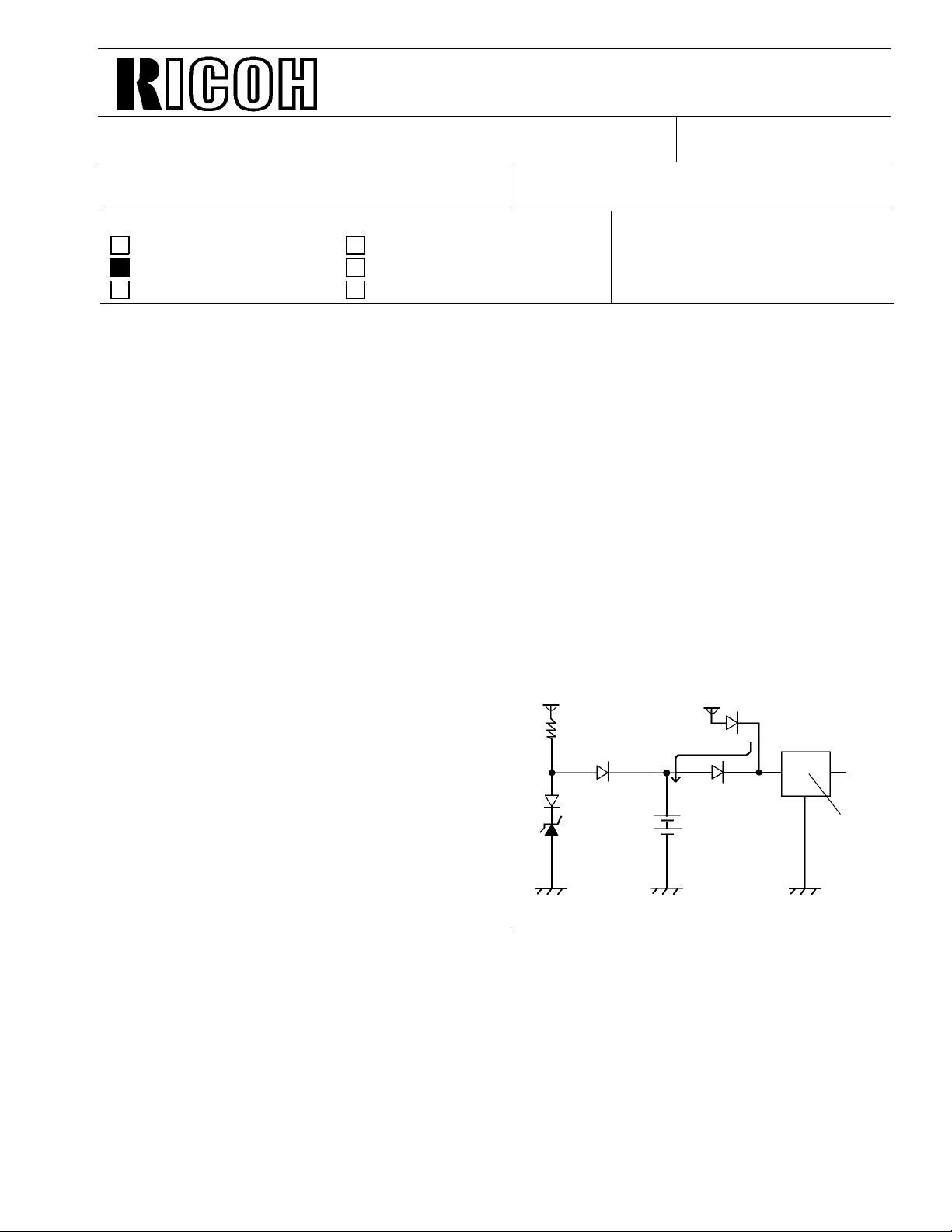
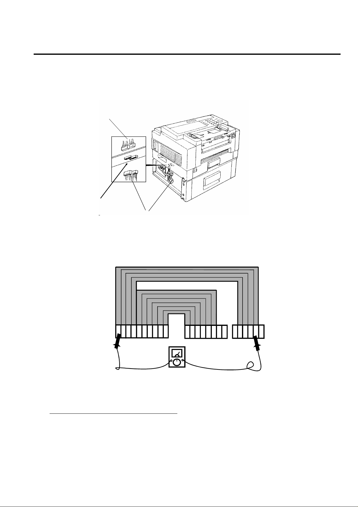
[Cause]
Power loss from the memory back-up battery on FCU caused by excessive charge current, for
the following reasons.
(1) Leak current from Diode
The battery is charged after it is alread y
24V
24V
fully charge d. This type of bat te ry
is damaged if this occurs.
(2) Excessive charge voltage (CFO,
CS1,LHO) The target charge voltage
was 6.2V against 6.4V or under which is
recommended by the battery maker.
This margin was too small for this battery.
Zener
Diode
Battery
COM
[Modification]
See MB C Series-048A.
OUT
Page 2

Technical Bulletin No. Multi-001
SUBJECT: Memory Back-up Battery
[Action Taken]
1. Install the modified FCU to deal with customer claims.
2. Request technicia ns no t to turn off the main power if a document is sto red
in the memory.
[Note]
• Stored data other than docume nts is not erased even if the main power goes down.
DATE:
Jan. 19, 1995
Page 3
Technical Bulletin No. Multi-002
SUBJECT: Toner Spillage during Transportation
PREPARED BY: Y. Okunishi
CHECKED BY: M. Iwasa
CLASSIFICATION:
Action Required Revision of service manual
Troubleshooting Information only
Retrofit Information Preventive Action
Background: Machines have been sent to cu sto mers after pre-installation and sent back to the
service center for repair.
Problem: Toner had spread inside the machin e du ring transportation.
Cause: Toner leaked from the development unit, the toner cartridge, or somewhe re
in the toner path during tran sportation.
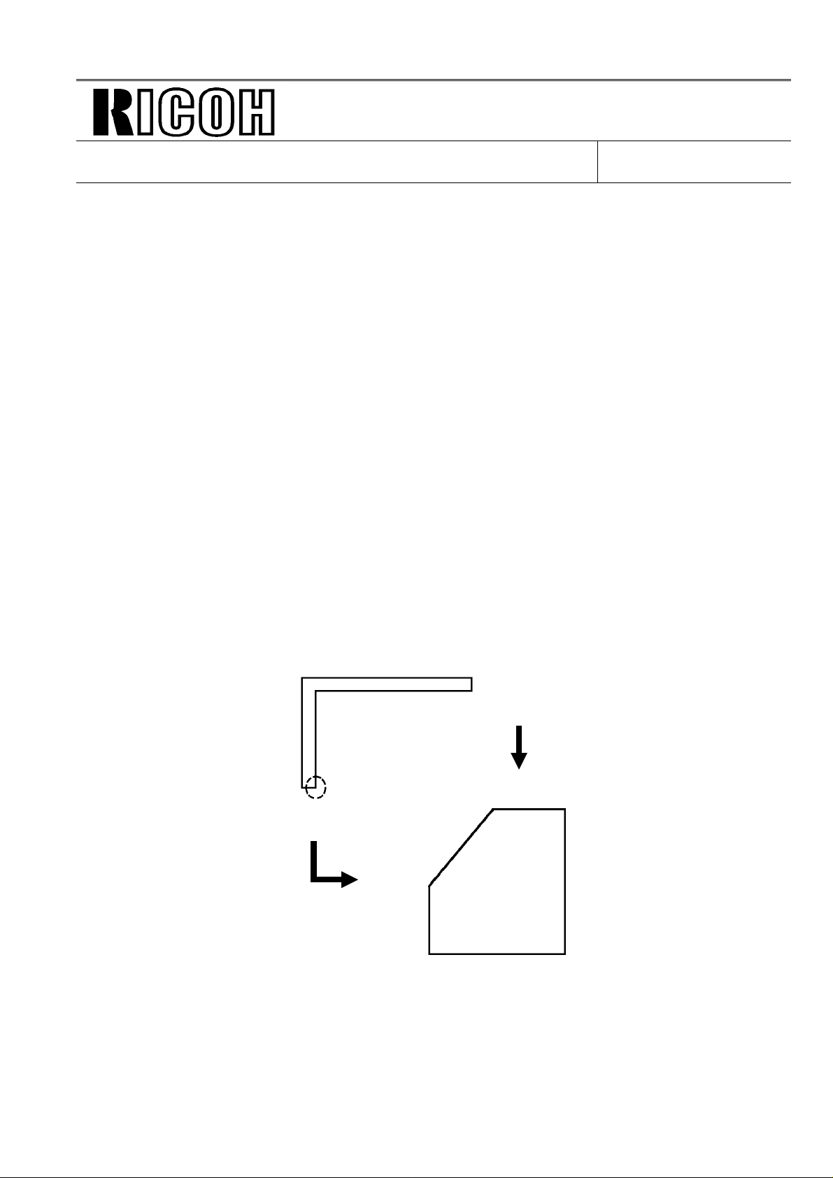
Preparation for transportation:
(1) Transportation withou t he avy vibra tio n
(Example: A technician should carry the machine with care.)
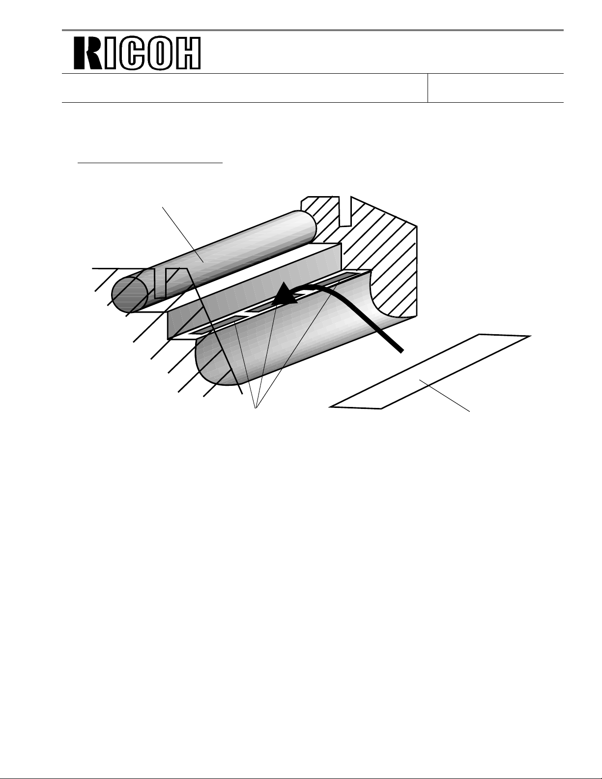
• F/L series fax machines:
The development unit can be connected to a CTM with toner.
However, the toner path under the CTM must be covered by some
adhesive tape. See the attached illust rat ion.
• C series fax machines:
Follow RTB No. CSO-006
• Other order machines:
Follow (2) below.
FROM: 2nd T.S. Section
MODEL:
All laser plain paper fax
machines
DATE:
Jul. 15.1995
(2) Transportation with heavy vibration
(If a third party handles the transportation, follow this procedure.)
• F/L series fax machines:
Remove the development unit and the CTM fro m the machin e if toner
has been installed. They must not be delivered in the same box as the
machine, because they contain toner which may spill out. The toner
inside the machine must be clean ed away or th e toner path under the
CTM must be covered with tape.
• C series fax machines and others:
Remove the development unit and CTM (or Toner Cartridge) from
the machine if toner has been inst alle d, and clean the toner from
inside the machine.
The removed development unit and CTM must not be delivered
in the same box as the machine.
Page 4
Technical Bulletin No. Multi-002
SUBJECT: Toner Spillage during Transportation
Inside of FX6 and LSO
Drum
DATE:
Jul. 15.1995
Toner path
Note: Adhesion of the tap e sho uld not be strong. Otherwise, it may n ot be ta ken off
cleanly from the machine, or th e toner path may be damaged whe n it is take n
off.
Please request tape samples for th e FX6 and LSO from Ricoh.
Adhesive tape
Page 5
Technical Bulletin No. Multi-003
Page 1/2
SUBJECT: Harness for PFU
PREPARED BY: Y. Okunishi
CHECKED BY: M. Iwasa
CLASSIFICATION:
Action Required Revision of service manual
Troubleshooting Information only
Retrofit Information Other
Problem: The Paper Feed Unit may not work correctly.
Cause: Wires of the harness (H511 5528) from th e FCU to th e rela y co nnectors for the paper
feed unit (PFU) are not allocated properly.
Affected machines:
Fax 3500L S/N R8750600001 ~ R87 5070 06 00
NRG9665 S/N 6355060620 ~ 6355060671
Savin Fax 3670 S/N 0950600001 ~ 0950700120
Fax 5600L S/N M2050600001 ~ M20 5070 05 00
Lanier Fax 7550 S/N L7555060677 ~ L7555060780
Omnifax L540 S/N L5405060271 ~ L5405060330
FROM: 2nd T.S. Section
MODEL: Fax3500L(USA),
NRG9665(USA), Savin Fax3670
Fax5600L(USA),
Lanier Fax7550, Omnifax L540
DATE:
July 31, 1995
Action Required:
The harness should be checked before the start of the PFU installation because th e
FCU or the PFU PCB may become damaged.
Follow the attached proce du re be fo re PFU installation and chang e th e ha rne ss
to a new one if it is bad.
Page 6
CN B
RTB No. Multi-003
Page 2/2
Harness Check Procedure
1. Remove the Rear Cover and Left Cover.
2. Unplug the connector CN28 on the FCU.
3. Unplug the connect ors CN A and CN B on the relay con ne ctor board located at the bot to m o f
Main Frame.
Harness from FCU
(CN A & B)
Main Frame
Paper Feed Unit (PFU)
Relay connectors
Harness from PFU
4. Check the continuity of the harness pin by pin using a mult imet er.
See below for what the correct allocation of all wires of the harness should be.
ABCDEFGHI
CN28 (to FCU)
J1234
5
6XX1234XX
CN A
(to PFU)
View from the side without the plastic cove r
Check the continuity of the following.
A of CN28 to 4 of CN B
⇓ ⇓
D of CN28 to 1 of CN B
E of CN28 to 6 of CN A
⇓ ⇓
J of CN28 to 1 of CN A
Page 7

Page 1/3
Technical Bulletin No. Multi - 004A
SUBJECT: Fusing Unit
PREPARED BY: Y.Okunishi
CHECKED BY: S.Fujii
CLASSIFICATION:
Action Required Revision of service manual
Troubleshooting Information only
Retrofit Information Other
A: "NOTE" is added to page 2/3.
SYMPTOM:
Background on received and copied documents.
Cause:
Hot Roller failure as a result of not changing the Cleaning Pad at the 10K PM.
Failure to change the Cleaning Pad results in dirty Strippers and Thermostat and
then Hot Roller failure.
As the machine warms up from the standby temperature to the fusing
temperature, it is exposed to slight overheating before the temperature levels
off. This leads to softening of the Teflon layer on the Hot Roller. As a result, the
Teflon layer peels off in the areas where the Strippers and other parts come in
contact with it. Dirty Strippers and Thermostat put more stress on the Hot Roller and
cause premature Hot Roller failure.
Also, the dirty Thermistor causes the Hot Roller to overherat and fail prematurely.
FROM: Quality Assurance Center
DATE:
Oct. 15, 1996
MODEL:
CSO, CRO, CS1, CFO,
CGO
A second cause can be a damaged (bent ) Thermistor from a previous service visit.
The damaged Thermistor causes the Hot Roller to overheat and fail prematurely.
SOLUTION:
Ricoh recommends replacing the Cleaning Pad at the 10K PM. However, this is
sometimes ignored. Realizing this, Ricoh will conduct the following modifications to
protect the Hot Roller from the failure mentioned above.
No. Old Part New Part Description Qty Used Interchangeability
1 H0812121 H0812123 Stripper Spring 2 → 2 X / O
H0812120 H5132119 Stripper
2
3
H0812137
H0815035
H0812141
03130080B
(Separation Pawl)
Thermistor Assembly
Thermistor
Bracket
Screw - M3x8
2 → 2 X / O
1 → 0
1 → 1
1 → 1
0 → 1
X / O as an
assembly
4 H0812100 H0819600 Hot Roller Kit 1 → 1 X / O
Page 8
Page 2/3
Technical Bulletin No. Multi - 004A
SUBJECT: Fusing Unit
DATE:
Oct. 15, 1996
Hot Roller Kit:
The hot rollers shipped from the SPC in Japan will be replaced by the
Hot Roller Kit in July.
This kit will be comprised of the following: Hot Roller, Cleaning Pad, Thermistor,
Thermistor Bracket, Screw, Strippers (2), Stripper Springs (2) and Installation Sheet.
The individual Hot Roller will be no longer available. The Cleaning Pad will
continue to be a Service Part.
Ricoh recommends change of the above modified parts and Cleaning Pad when the failed
Hot Roller is replaced with the new one.
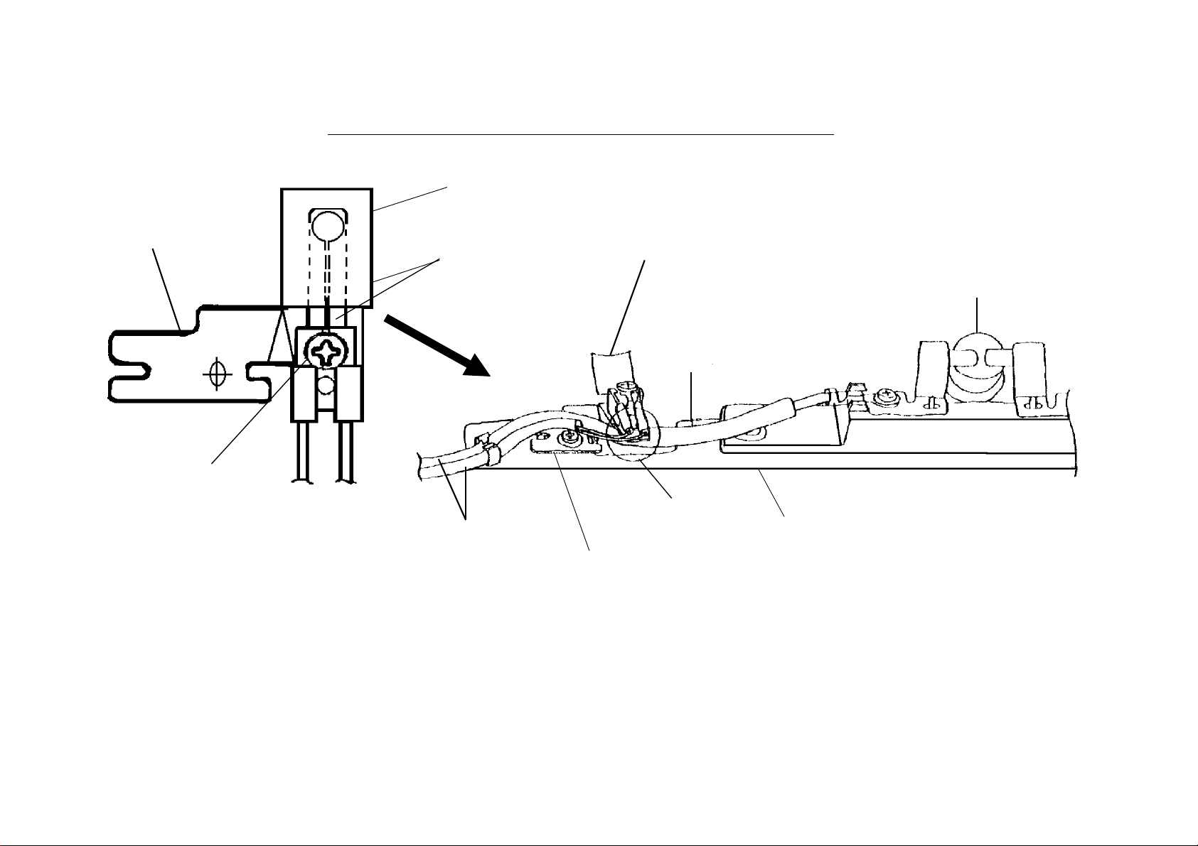
NOTE
(A): Please refer to the following instructions and fix the cover to the fusing unit
and check that the harness is not pinched before installing the fusing unit in the
machine.
If the metal wire of the harness contacts the thermistor bracket, a no power
condition may occur. Please check the thermistor harness if this occurs.
Fusing Cover
(Bad)
Edge of the cover may damage
the harness
Edge
(Good)
Fusing Unit
Page 9
Installation Procedure for the Thermistor
1. Assemble the thermistor and the bracket
with the screw.
Bracket - Thermistor
H0812141
Thermistor - Fusing Unit
H0815035
Do not bendthis part
2. Install the
Thermistor Ass’y
( ✻ 4)
Thermistor - Fusing Unit
H0815035
Harness - Thermostat
(✻ 3)
Page 3/3
Thermostat - Fusing Unit
H0812134
Screw - M3 x 8
03130080B
(✻ 1)
Note: Set the projection on
the thermistor into
the hole in the bracket.
Note: ✻ 1 Place the thermostat harness under the part of the bracket.
✻ 2 Do not cross the thermostat harness and the thermistor harness.
✻ 3 Push the thermistor head (sensor) gently against the hot roller witha finger to make sure that the thermistor
head touches the hot roller surface. Do not push it strongly.
✻ 4 Do not bend the thermistor neck (spring plate) when installing or cleaning it .
If the thermistor is bent, replace it.
(✻ 2)
Bracket - Thermistor
H0812141
Stay - Fusing Unit - Upper
H0812175
Page 10
T
Model:
FX4, FX6, FX6MK2, FX6CD, FX7, LX7, LSO, AD1
echnical
ulletin
B
Date:
31-Aug-97
No:
PAGE: 1/4
005
Subject:
From:
Classification:
The NEST card has been released for Nest Autoroute function in fax machines and for fax
units in the AD series.
This technical bulletin contains the revisions to the Nest Autoroute service manual. Procedures
for reading and writing user-programmed data by RDS have been added. Only the
Installation section was changed.
For details on the models that can use the NEST card, please check the product launch
information for the models.
Novell Nest Autoroute Function
2nd Technical Support Section
Troubleshooting
Mechanical
Paper path
Other ( )
Part information
Electrical
Transmit/receive
Prepared by:
Action required
Service manual revision
Retrofit information
S.Yoshio
RC RE ASIA
✶✶ ✶✶ ✶✶
Page 11

T
Model:
INSTALLATION May 20th,1997
INSTALLING THE NEST CARD
FX4, FX6, FX6MK2, FX6CD, FX7, LX7, LSO, AD1
echnical
ulletin
B
Date:
31-Aug-97
No:
PAGE: 2/4
005
2.2. INSTALLING THE NEST CARD
CAUTION
Before installing the NEST card,do the following:
1.Print out all messages stored in the memory.
2.Print out the lists of user – programmed items and the system parameter list.
2.2.1. Function Upgrade Card Type 140 Plus Novell
Note
The following installation procedure i nitializes (erases) all the user-programmed data
•
stored in the card, if the Function Upgrade Card already installed in the machine is
replaced with a NEST card.
NEST
TM
Installation Procedure (Without a Function Upgrade Card)
Turn off the main switch.
•
Install the battery on the NEST card.
•
Turn on the battery switch.
•
Install the NEST card in the slot.
•
Turn on the main switch.
•
Print the system parameter list and make sure that “NEST” is listed as an option on
•
the list.
Installation Procedure
(Replacing a Function Upgrade Card with the NEST card)
Read and back-up the user-programmed data stored in the Function Upgrade Card
•
with RDS.
Turn off the main switch.
•
Remove the Function Upgrade Card from the slot.
•
Install the battery on the NEST card and turn on the battery swit ch.
•
Install the NEST card in the slot.
•
Turn on the main switch.
•
Print the system parameter list and make sure that “NEST” is listed as an option on
•
the list.
Write the backed-up data to the NEST card.
•
Page 12

T
Model:
May 20th,1997 INSTALLATION
FX4, FX6, FX6MK2, FX6CD, FX7, LX7, LSO, AD1
echnical
ulletin
B
Date:
31-Aug-97
INSTALLING THE NEST CARD
No:
PAGE: 3/4
005
When the NEST card is replaced with another NEST card, do the
following so the machine can recognize the new card.
1. Turn off the main switch
2. Remove the old card.
3. Turn on the machine without the card and turn off.
4. Install the new card.
5. Turn on the main switch.
CAUTION
The IC card contains a lithium battery.
The danger of explosion exists if a battery of this type is incorrectly replaced.
Replace only with the same or an equivalent type recommended by the
manufacturer. Discard used batteries in accordance with the manufacturer’s
instructions
.
Page 13

T
Model:
INSTALLATION May 20th,1997
INSTALLING THE NEST CARD
FX4, FX6, FX6MK2, FX6CD, FX7, LX7, LSO, AD1
echnical
ulletin
B
Date:
31-Aug-97
PAGE: 4/4
No:
005
2.2.2. Feature Expander Type 100 2M Plus Novell NEST
Note
The following installation procedure initializes (erases) all the data stored in the card,
•
if the Feature Expander already installed in the machine is replaced with a NEST
card.
Installation Procedure
Turn off the main switch.
•
Install the NEST card in the slot in the machine.
•
Turn on the main switch.
•
Print the system parameter list and make sure that “NEST” is listed as an option on
•
the list.
When the NEST card is replaced with another NEST card, do the following so the
machine can recognize the new card.
1. Turn off the main switch.
2. Remove the old card.
3. Turn on the machine without the card and then turn off.
4. Install the new card.
5. Turn on the main switch.
Page 14

T
Model:
ISDN Option
echnical
ulletin
B
Date:
30-Nov-97
No:
PAGE: 1/1
Multi - 006
Subject:
From:
Classification:
This technical bulletin informs of the settings required when a machine is connected to the
US National ISDN network
Models: CFO, CGO, LHO, FX4, ADAM
• Subscriber Number
Input the subscriber number given by the telephone company at :
1.G4 SUBSCRIBER NO.1 (MAIN)
2.G3 SUBSCRIBER NO.1 (MAIN)
• SPID Number (Service Profile Identification Number)
Input the SPID number given by the telephone company at :
US National ISDN
IPP Business Division Technical Service Dpt.
Troubleshooting
Mechanical
Paper path
Other ( )
Part information
Electrical
Transmit/receive
Prepared by:
Action required
Service manual revision
Retrofit information
H.Kamiya
1.G4 SUBSCRIBER NO.2 (Sub)
2.G3 SUBSCRIBER NO.2 (Sub)
Note: Input a ”_” (pause) before the SPID number.
• G4 Internal Switches
SW No. Bit Setting Definition
SW11 Bit1 0: Dynamic TEI Type of TEI used (Layer 2) (Default)
Bit2 1: Yes Attachment of calling p arty number (L3 SET UP)SW13
Bit5 1: Yes Attachment of channel information element (L3
CONN)
Bit0 1: Speech ISDN G3 information transfer capability (L3)SW14
Bit5 1: Keypad facility Called ID mapping (L 3)
SW15 Bit7 1: On Transmission of STAT in reply to STAT_ENQ
received in the U0 state.
SW19
Bit0 1: Permanent Permanence of the link (L2)
Bit2 1: On SPID procedure (L2)
Note: After completing a G4 service mode operation, turn off the machine and turn it
back on to make the new settings take effect.
RC RE ASIA
∗
Bit3 1: On G4 SPID procedure (L2)
Page 15

T
Model:
F14, F16, F16MK2, LSO, LSO2, FR6
echnical
B
ulletin
Date:
15-Feb-98
No:
PAGE: 1/1
Multi - 007
Subject:
From:
Classification:
The following parts have been packed with the PIF since December 1997. They had been
packed with the main frame. (No instruction change)
1) Grounding Plate Ass’y
① H515 3185 : Grounding Plate
2) Two screws
Printer I/F Type 200
QAC Field Information Dept.
Troubleshooting
Mechanical
Paper path
Other ( )
② H515 3188 : Gasket
Part information
Electrical
Transmit/receive
Prepared by:
Action required
Service manual revision
Retrofit information
Y.Okunishi
[①]
[②]
Note: This change is not applied for the Siemens FX770/790 yet.
RC RE ASIA
∗ ∗ ∗
Page 16

RICOH Technical
Model:
LSO, CRO, CS1, AFO, AF2, K200
Bulletin
Date:
31-May-98
No:
PAGE:
Multi - 008
1/8
Subject:
From:
Classification:
Attached please find the list of the ROMs for the year 2000 problem and the procedure for
making R200 ROMs from the ROM file s.
Note:
Please refer to RTB nos. General 11 and 14 for details.
·
8 ROMs for the K200 are combined in one file.
·
ROMs for the year 2000 problem
QAC Field Information Dept.
Troubleshooting
Mechanical
Paper path
Other ( )
Part information
Electrical
Transmit/receive
Prepared by:
Action required
Service manual revision
Retrofit information
Y.Okunishi
RC RE ASIA
* * *
Page 17

RICOH Technical
Model:
LSO, CRO, CS1, AFO, AF2, K200
Bulletin
Date:
31-May-98
No:
PAGE:
Multi - 008
2/8
ROMs for the year 2000 May 29, 1998
Y.Okunishi
Product
Code
CSO H0817138 yes CSO7138 8552 c30usa H081-20 3000L RICOH US 91/12 93/4 16,747 2M ROM (1ROM/unit)
CS1 H5117150B yes CS17150B 6A91 c31usa H511-20 3500L RICOH US 93/6 96/3 31,766
CR0 H5107121B yes CRO7121B 23AB c60usa H510-20 2500L RICOH US 93/5 95/4 26,535
New ROM
No.
H0817136A yes CSO7136S 77A7
H0817139E yes CSO7139E 3C77 c30tel 28 L40 L41 Omnifax US 92/1 93/5 5,181
H0817124A yes CSO7124A 0772 c30eur 40 3000L 3000L RICOH Europe 92/3 95/ 11 37,716
H0817123A no CSO7123A 0078 c30f ra 70 3000LF RICOH France 93/4 95/9 393
H0817121A yes CSO7121A FA57 c30hcs 30 3660 Infotec Europe 92/10 94/8 15,528
H0817122A yes CSO7122A D225 c30asi 51 3000L RICOH Asia 92/3 96/10 18,523
H0817140M yes CSO7140M 859C c30tai 23 3000L RICOH Taiwan 92/3 95/11
H0817128B no CSO7128B E8C5 c30chi 54 3000L RICOH China 93/7 95/11
H0817159N yes CSO7159N C3CE c30opt
Test File name Check
sum
ROM Code Model code Model Brand Area Sold from Sold by No. of sold
23 3200L 91/12 95/ 11 18,242
24 3100L 93/2 95/2 21,863
21 9660 NRG 92/3 92/7 71
22 9661 92/3 94/2 1,651
26 3660 SAVIN 92/2 93/4 1,372
27 3620 92/1 93/4 1,917
TOTAL
c30usa
•
H151-65•SW:HCS•,H151-
73(•:RE),H151-83(•:GES)
25 2600L RICOH US 94/9 95/3
29 L41 92/1 93/5 8,008
TOTAL
46 3000L RICOH Switzerland 92/10 95/6 4,179
60 9660 NRG Europe 93/3 95/8 15,659
TOTAL
80 92/4 95/9 6,206
90 9660F NRG 92/4 95/9 2, 164
TOTAL
59 9660 NRG 94/3 96/4 2,837
55 - Ricoh Korea ?
TOTAL
Option Europe ? Language Kit
21 9669 NRG 93/6 95/9 700
22 L46 Omnifax 93/6 95/12 11,472
27 3670 SAVIN 93/7 95/9 3,106
3/8
21 9650 NRG 93/7 95/7 832
TOTAL
units
61,863
8,000
13,189
57,554
8,763
36,888
1,251
981
47,044
Note
Page 18

RICOH Technical
H5107120B yes CRO7120B F5BF c60eur 30 3661 Infotec Europe 93/9 94/9 5,564
H5107123B yes CRO7123B 0E88 c60fra 33 3661F Infotec France 94/4 95/9 242
H5107132G yes CRO7132G 37F5 c60asi 51 2500L RICOH Asia 93/12 96/1 5,955
H5107131B yes CRO7131B 23A3 c60tai 53 2500L RICOH Taiwan 94/10 97/6
AFO H0847130K yes AFO7130K D8D3 a20usa H084-20 500 RICOH Taiwan 92/4 93/4
H0847140L yes AFO7140L 6B6A a20eur 44 500 RICOH Europe 91/8 94/10
H0847142H no AFO7142H 94D0 a20fra 83 500 RICOH France 92/4 94/3
H0847143L yes AFO7143L 350F a20hcs 34 3301 Infotec Europe 91/8 95/4
H0847141L yes AFO7141L 3F13 a20asi 51 500 RICOH Asia 91/10 96/11 13,696
H0847150K yes AFO7150K 2A40 a20opt
AF1 H0857135B yes AF17135B FCDF a21chi H085-54 580 RICOH China 93/8 96/5
AF2 H0867130K yes AF27130K 9BDF a22usa 20 550 RICOH US 92/1 96/2
H0867140L yes AF27140L 3C35 a22eur 44 550 RICOH Europe 91/8 95/3 10,824
H0867142H c heckingAF27142H 583D a22fra 73 3305 Infotec France - - 0 RIF is checking the
H0867143L yes AF27143L 0CE0 a22hcs 34 3305 Infotec Europe 91/8 95/9
H0867141L yes DAD8 a22asi 51 550 RICOH Asia 92/2 96/2 12,181
H0867131A yes AF27131A 9BC3 a22tai 53 550 RICOH Taiwan 94/8 96/2
H0867150L yes AF27150L E725 a22opt
Bulletin
22 L42 Omnifax 93/9 95/3 6,848
27 3630 SAVIN 93/7 95/3 2,136
40 2500L RICOH 93/9 95/7 11,418
60 9650 NRG 93/9 95/8 5,632
43 2500LF RICOH 93/10 95/9 2,012
63 9650F NRG 93/10 95/9 931
59 9650 NRG 94/1 95/9 1,107
56 500 RICOH Vietnam 92/11 94/5 1,650 KD
H15146(•:RICOH),H
151-54(SW:HCS)
90 9620 NRG 92/4 93/9 1,446
83 550 RICOH 95/4 95/9 100
93 9620 NRG 92/4 94/9 170
59 Nashua Asia 92/2 96/1 1,662
H15147(•:RICOH),H
15155(SW:HCS),H15193(•:NASHUA)
- Option Europe ? Language Kit
- Option Europe ? Language Kit
PAGE:
TOTAL
TOTAL
TOTAL
TOTAL
TOTAL
TOTAL
TOTAL
TOTAL
36,351
22,614
3,185
7,062
777
365
6,817
1,231
2,892
15,346
5,040
14,934
12,270
ROM.
270
6,583
13,843
109
Page 19

RICOH Technical
Bulletin
PAGE:
4/8
K200 H0087260J
H0087261J
H0087262J
H0087263J
H0087264J
H0087265J
H0087266J
H0087267J
H0087270F
H0087271F
H0087272F
H0087273F
H0087274F
H0087275F
H0087276F
H0087277F
H0087320F
H0087321F
H0087322F
H0087323F
H0087324F
H0087325F
H0087326F
H0087327F
H0087280H
H0087281H
H0087282H
H0087283H
H0087284H
H0087285H
H0087286H
H0087287H
H0087330H
H0087331H
H0087332H
H0087333H
H0087334H
H0087335H
H0087336H
H0087337H
H0087290C
H0087291C
H0087292C
H0087293C
H0087294C
H0087295C
H0087296C
H0087297C
yes H0087260 FC1E
EBE0
B88F
08B2
7AA0
C2F0
28D7
CE5E
yes H0087270 451C
78BA
3FA2
C44F
7B14
4DA3
7C16
380B
yes H0087320 4527
7967
3FA2
C44F
7B14
4DA3
7C16
380B
yes H0087280 1956
CB16
4E46
C3F4
799D
33A8
3EE5
6478
yes H0087330 1D20
64B7
4FAF
D4A1
7830
1EBB
C591
854A
yes H0087290 4A5D
5B24
416A
C54D
8882
683D
D331
E525
USA 20 7000L RICOH US 89/9 95/6
GMN 30 7000L RICOH Germany 89/10 93/7
GMN 40 6765 Infotec Germany 89/9 90/8
ENG 41 7000L RICOH UK 89/10 94/8
ENG 31 6765 Infotec UK 89/10 92/12
ITY 42 7000L RICOH Italy 89/10 91/10
790
1M ROM (8 ROMs/unit)
119
180
85
125
29
Page 20

RICOH Technical
H0087340C
H0087341C
H0087342C
H0087343C
H0087344C
H0087345C
H0087346C
H0087347C
H0087300E
H0087301E
H0087302E
H0087303E
H0087304E
H0087305E
H0087306E
H0087307E
H0087350E
H0087351E
H0087352E
H0087353E
H0087354E
H0087355E
H0087356E
H0087357E
H0087310H
H0087311H
H0087312H
H0087313H
H0087314H
H0087315H
H0087316H
H0087317H
H0087360H
H0087361H
H0087362H
H0087363H
H0087364H
H0087365H
H0087366H
H0087367H
yes H0087340 4A68
5BD1
416A
C54D
8882
683D
D331
E525
yes H0087300 4A2A
3680
403B
9F7C
8900
DB80
6C4A
1B91
yes H0087350 4A35
372D
403B
9F7C
8900
DB80
6C4A
1B91
yes H0087310 196E
CB4C
4E46
C3F4
799A
3385
3EE5
6478
yes H0087360 1D38
64ED
4FAF
D4A1
782D
1E98
C591
854A
ITY 32 6765 Infotec Italy 89/10 92/9
FRN 43 7000L RICOH France 89/10 92/3
FRN 33 6765 Infotec France 90/7 91/3
UNV 44 7000L RICOH Europe/Asia 89/9 94/1
UNV 34 6765 Infotec Europe 90/1 92/11
Bulletin
PAGE:
5/8
41
137
156
387
38
END
Page 21

RICOH Technical
Bulletin
ROM writing procedure for K200 ROMs
1. ROM Writing
This will vary depending on the ROM writer buffer capacity.
This is an example with a buffer RAM capacity of 512KB.
During the first load, 512KB is sent.
During he first load, 0H~7FFFFH can be loaded.
During the second, 800000H~FFFFFH can be loaded.
Since the K200 is 1MB, the sending is completed after 512KB worth has been sent
twice.
First Time
1-1) Transfer to the ROM writer.
Motorola-S Format
Receiving location address 00000000
Send/Receive buffer RAM start 00000000
Sending buffer RAM end Device capacity
1-2) Program on the ROM
Set program 16-bit series
Device Count 4
Device Start 00000000
Buffer RAM Start 00000000
Data Type BIGENDIAN
PAGE:
6/8
Second Time
2-1) Transfer to the ROM writer.
Motorola-S Format
Receiving location address 00080000
Send/Receive buffer RAM start 00000000
Sending buffer RAM end Device capacity
2-2) Program on the ROM
Set program 16-bit series
Device Count 4
Device Start 00000000
Buffer RAM Start 00000000
Data Type BIGENDIAN
When the buffer RAM capacity is 1MB, the RAM writing is as follows.
1MB can be sent during the first load.
OH~FFFFFH can be loaded.
Since the K200 is 1MB, it can be transferred all at once.
Page 22

RICOH Technical
First Time
1-1) Transfer to the ROM writer.
Motorola-S Format
Receiving location address 00000000
Send/Receive buffer RAM start 00000000
Sending buffer RAM end Device capacity
1-2) Program on the ROM
Set program 16-bit series
Device Count 4
Device Start 00000000
Buffer RAM Start 00000000
Data Type BIGENDIAN
Second Time
2-1) Transfer to the ROM writer.
Since 1MB can be sent the first time, this is not necessary.
2-2) Program on the ROM
Set program 16-bit series
Device Count 4
Device Start 00000000
Buffer RAM Start 00080000
Data Type BiGENDIAN
Bulletin
PAGE:
7/8
ROM locations (Top view of MBU)
3-8 (3’) 3-0 (4’)
2-8 (1’) 2-0 (2’)
1-8 (3) 1-0 (4)
0-8 (1) 0-0 (2)
() The number in the parentheses is the ROM writer socket number.
[‘] The second time is indicated.
The ROM part numbers start from 0-8.
(Ex: For the FAX7000L(US), 0-8:H0087260, 3-0:H0087267)
Page 23

RICOH Technical
Check Sum Chart
ROM location
Model
K200USA FC1E EBE0 B88F 08B2 7AA0 C2F0 28D7 EC5E
K200GMN-R 451C 78BA 3FA2 C44F 7B14 4DA3 7C16 380B
K200G<M-K 4527 7967 3FA2 C44F 7B14 4DA3 7C16 380B
K200ENG-R 1956 CB16 4E46 C3F4 799D 33A8 3EE5 6478
K200ENG-K 1D20 64B7 4FAF D4A1 7830 1EBB C591 854A
K200ITY-R 4A5D 5B24 416A C54D 8882 683D D331 E525
K200ITY-K 4A68 5BD1 416A C54D 8882 683D D331 E525
K200FRN-R 4A2A 3680 403B 9F7C 8900 DB80 6C4A 1B91
K200FRN-K 4A35 372D 403B 9F7C 8900 DB80 6C4A 1B91
K200UNV-R 196E CB4C 4E46 C3F4 799A 3385 3EE5 6478
K200UNV-K 1D38 64ED 4FAF D4A1 782D 1E98 C591 854A
R: Ricoh, K : Kalle (Infotec)
0-8 0-0 1-8 1-0 2-8 2-0 3-8 3-0
Bulletin
PAGE:
8/8
Page 24

T
echnical
B
ulletin
RTB Correction
Reissue date: 30-Jun-98
The items in bold italic have been correction or added.
Model:
CSO, CRO, CS1, AFO, AF2, K200
Date:
31-May-98
No:
PAGE: 1/5
Multi-008
A
Subject:
From:
Classification:
Attached please find the list of ROMs for the year 2000
The ROM files have been saved in the Ricoh QAC server except for the K200 ROMs.
(EP ROMs for the K200 will be prepared by the beginning of June.)
Note:
• Please refer to RTB nos. General 11 and 14 for details.
ROMs for the year 2000 problem
QAC Field Information Dept.
Troubleshooting
Mechanical
Paper path
Other ( )
Part information
Electrical
Transmit/receive
Prepared by:
. (The list was updated.)
Y. Okunishi
Action required
Service manual revision
Retrofit information
RC RE ASIA
∗ ∗ ∗
Page 25

T
Model:
CSO, CRO, CS1, AFO, AF2, K200
echnical
B
ulletin
Date:
31-May-98
No:
PAGE: 2/5
Multi-008
ROMs for the year 2000
Product
Code
CSO H0817138 8552 H081-20 3000L RICOH US 2M ROM
CS1 H5117150B 6A91 H511-20 3500L RICOH US
CR0 H5107121B 23AB H510-20 2500L RICOH US
New ROM
No.
H0817136A 77A7 25 2600L RICOH US
H0817139E 3C77 28 L40 Omnifax US
H0817124A 0772 40 3000L RICOH Europe
H0817123A 0078 70 3000LF RICOH France
H0817121A FA57 30 3660 Infotec Europe
H0817122A D225 51 3000L RICOH Asia
H0817140M 859C 23 3000L RICOH Taiwan
H0817128B E8C5 54 3000L RICOH China
H0817159N C3CE
H5107120B F5BF 30 3661 Infotec Europe
H5107123B 0E88 33 3661F Infotec France
H5107132G 37F5 51 2500L RICOH Asia
H5107131B 23A3 53 2500L RICOH Taiwan
Check
sum
Model code Model Brand Area Note
23 3200L (1ROM/unit)
24 3100L
21 9660 NRG
22 9661
26 3660 SAVIN
27 3620
29 L41
46 3000L RICOH Switzland
60 9660 NRG Europe
80
90 9660F NRG
59 9660 NRG
55 - Ricoh Korea
H151-65•SW:HCS
H151-73(FRN:Ricoh)
H151-83(FRN:GES)
21 9669 NRG
22 L46 Omnifax
27 3670 SAVIN
21 9650 NRG
22 L42 Omnifax
27 3630 SAVIN
40 2500L RICOH
60 9650 NRG
43 2500LF RICOH
63 9650F NRG
59 9650 NRG
•
Option Europe Language Kit
25-Jun-98
Page 26

T
Model:
AFO H0847130K D8D3 H084-20 500 RICOH Taiwan
AF1 H0857135B FCDF H085-54 580 RICOH China
AF2 H0867130K 9BDF 20 550 RICOH US
CSO, CRO, CS1, AFO, AF2, K200
H0847140L 6B6A 44 500 RICOH Europe
H0847142H 94D0 83 500 RICOH France
H0847143L 350F 34 3301 Infotec Europe
H0847141L 3F13 51 500 RICOH Asia
H0847150K 2A40 H151-46(FRN:RICOH)
H0867140L 3C35 44 550 RICOH Europe
H0867142H 583D 73 3305 Infotec France
H0867143L 0CE0 34 3305 Infotec Europe
H0867141L DAD8 51 550 RICOH Asia
H0867131A 9BC3 53 550 RICOH Taiwan
H0867150L E725 H151-47(FRN:RICOH)
echnical
56 500 RICOH Vietnam KD
H151-54(SW:HCS)
90 9620 NRG
83 550 RICOH
93 9620 NRG
59 9620 NRG Asia
H151-55(SW:HCS)
H151-93(FRN:NASHUA)
B
ulletin
Date:
31-May-98
No:
Option Europe Language Kit
Option Europe Language Kit
PAGE: 3/5
Multi-008
K200 H0087260J
H0087261J
H0087262J
H0087263J
H0087264J
H0087265J
H0087266J
H0087267J
H0087270F
H0087271F
H0087272F
H0087273F
H0087274F
H0087275F
H0087276F
H0087277F
H0087320F
H0087321F
H0087322F
H0087323F
H0087324F
H0087325F
H0087326F
H0087327F
FC1E
EBE0
B88F
08B2
7AA0
C2F0
28D7
CE5E
451C
78BA
3FA2
C44F
7B14
4DA3
7C16
380B
4527
7967
3FA2
C44F
7B14
4DA3
7C16
380B
H008-20 7000L RICOH US 1M ROM
(8 ROMs/unit)
30 7000L RICOH Germany
40 6765 Infotec Germany
Page 27

T
Model:
CSO, CRO, CS1, AFO, AF2, K200
echnical
B
ulletin
Date:
31-May-98
No:
PAGE: 4/5
Multi-008
H0087280H
H0087281H
H0087282H
H0087283H
H0087284H
H0087285H
H0087286H
H0087287H
H0087330H
H0087331H
H0087332H
H0087333H
H0087334H
H0087335H
H0087336H
H0087337H
H0087290C
H0087291C
H0087292C
H0087293C
H0087294C
H0087295C
H0087296C
H0087297C
H0087340C
H0087341C
H0087342C
H0087343C
H0087344C
H0087345C
H0087346C
H0087347C
H0087300E
H0087301E
H0087302E
H0087303E
H0087304E
H0087305E
H0087306E
H0087307E
H0087350E
H0087351E
H0087352E
H0087353E
H0087354E
H0087355E
H0087356E
H0087357E
H0087310H
H0087311H
H0087312H
H0087313H
H0087314H
H0087315H
H0087316H
H0087317H
1956
CB16
4E46
C3F4
799D
33A8
3EE5
6478
1D20
64B7
4FAF
D4A1
7830
1EBB
C591
854A
4A5D
5B24
416A
C54D
8882
683D
D331
E525
4A68
5BD1
416A
C54D
8882
683D
D331
E525
4A2A
3680
403B
9F7C
8900
DB80
6C4A
1B91
4A35
372D
403B
9F7C
8900
DB80
6C4A
1B91
196E
CB4C
4E46
C3F4
799A
3385
3EE5
6478
41 7000L RICOH UK
31 6765 Infotec UK
42 7000L RICOH Italy
32 6765 Infotec Italy
43 7000L RICOH France
33 6765 Infotec France
44 7000L RICOH Europe/Asia
Page 28

T
H0087360H
H0087361H
H0087362H
H0087363H
H0087364H
H0087365H
H0087366H
H0087367H
1D38
64ED
4FAF
D4A1
782D
1E98
C591
854A
echnical
34 6765 Infotec Europe
B
ulletin
PAGE: 5/5
END
Page 29

T
echnical
B
ulletin
RTB Correction
Reissue date: 31-Jul-98
The items in bold italic have been correction or added.
Model:
CSO, CRO, CS1, AFO, AF2, K200
Date:
31-May-98
No:
PAGE: 1/4
Multi-008
B
Subject:
From:
Classification:
(B) : The attached ROM List has been corrected.
Attached please find the list of the ROM’s for the year 2000 problem. (The list was
updated.)
The ROM files have been saved in the Ricoh QAC server, except for the K200 ROMs.
(EPROMs for the K200 will be prepared by the beginning of June.)
Note:
• Please refer to RTBs General 11 and 14 for details.
ROM's for the year 2000
QAC Field Information Dept.
Troubleshooting
Mechanical
Paper path
Other ( )
Part information
Electrical
Transmit/receive
Prepared by:
Action required
Service manual revision
Retrofit information
Y.Okunishi
RC RE ASIA
∗ ∗ ∗
Page 30

T
echnical
B
ulletin
PAGE: 2/4
No:
Model:
CSO, CRO, CS1, AFO, AF2, K200
Date:
31-May-98
Multi-008
ROMs for the year 2000
Product
Code
CSO H0817138 8552 H081-20 3000L RICOH US 2M ROM
New ROM
No.
H0817136A 77A7 25 2600L RICOH US
H0817139E 3C77 28 L40 L41 Omnifax US
H0817124A 0772 40 3000L
H0817123A 0078 70 3000LF RICOH France
Check
sum
Model cord Model Brand Ar ea Note
23 3200L (1ROM/unit)
24 3100L
21 9660 NRG
22 9661
26 3660 SAVIN
27 3620
29 L41
RICOH Europe
3000L
46 3000L RICOH Switzerland
60 9660 NRG Europe
80
90 9660F NRG
B
25-Jun-98
H0817121A FA57 30 3660 Infotec Europe
H0817122A D225 51 3000L RICOH Asia
59 9660 NRG
55 - Ricoh Korea
H0817140M 859C 23 3000L RICOH Taiwan
H0817128B E8C5 54 3000L RICOH China
Ñ
H0817159N C3CE H151-65
H151-73(FRN:Ricoh)
H151-83(FRN:GES)
CS1 H5117150B 6A91 H511-20 3500L RICOH US
CR0 H5107121B 23AB H510-20 2500L RICOH US
H5107120B F5BF 30 3661 Infotec Europe
H5107123B 0E88 33 3661F Infotec France
SW:HCSÒ,
21 9669 NRG
22 L46 Omnifax
27 3670 SAVIN
21 9650 NRG
22 L42 Omnifax
27 3630 SAVIN
40 2500L RICOH
60 9650 NRG
43 2500LF RICOH
63 9650F NRG
Option Europe Language Kit
H5107132G 37F5 51 2500L RICOH Asia
59 9650 NRG
H5107131B 23A3 53 2500L RICOH Taiwan
Page 31

T
echnical
B
ulletin
PAGE: 3/4
Model:
CSO, CRO, CS1, AFO, AF2, K200
AFO H0847130K D8D3 H084-20 500 RICOH Taiwan
H0847140L 6B6A 44 500 RICOH Europe
H0847142H 94D0 83 500 RICOH France
H0847143L 350F 34 3301 Infotec Europe
H0847141L 3F13 51 500 RICOH Asia
56 500 RICOH Vietnam KD
H0847150K 2A40 H151-46(FRN:RICOH)
H151-54(SW:HCS)
AF1 H0857135B FCDF H085-54 580 RICOH China
AF2 H0867130K 9BDF 20 550 RICOH US
H0867140L 3C35 44 550 RICOH Europe
90 9620 NRG
H0867142H 583D 73 3305 Infotec France
83 550 RICOH
93 9620 NRG
H0867143L 0CE0 34 3305 Infotec Europe
H0867141L DAD8 51 550 RICOH Asia
59 Nashua Asia
H0867131A 9BC3 53 550 RICOH Taiwan
H0867150L E725 H151-47(FRN:RICOH),
H151-55(SW:HCS),
H151-
93(FRN:NASHUA)
K200 H0087260J
H0087261J
H0087262J
H0087263J
H0087264J
H0087265J
H0087266J
H0087267J
H0087270F
H0087271F
H0087272F
H0087273F
H0087274F
H0087275F
H0087276F
H0087277F
H0087320F
H0087321F
H0087322F
H0087323F
H0087324F
H0087325F
H0087326F
H0087327F
H0087280H
H0087281H
H0087282H
H0087283H
H0087284H
H0087285H
H0087286H
H0087287H
FC1E
E886
B88E
084C
7ABF
C07F
29B0
F658
451C
7566
3FA2
C2ED
7A62
1C05
7D08
2830
4527
7613
3FA2
C2ED
7A62
1C05
7D08
2830
1956
C7BC
4E45
C394
7A16
2A4E
3F82
56B3
20 7000L RICOH US 1M ROM (8
30 7000L RICOH Germany
40 6765 Infotec Germany
41 7000L RICOH UK
Date:
31-May-98
- Option Europe Language Kit
- Option Europe Language Kit
No:
Multi-008
ROMs/unit)
B
Page 32

T
echnical
B
ulletin
PAGE: 4/4
Model:
CSO, CRO, CS1, AFO, AF2, K200
H0087330H
H0087331H
H0087332H
H0087333H
H0087334H
H0087335H
H0087336H
H0087337H
H0087290C
H0087291C
H0087292C
H0087293C
H0087294C
H0087295C
H0087296C
H0087297C
H0087340C
H0087341C
H0087342C
H0087343C
H0087344C
H0087345C
H0087346C
H0087347C
H0087300E
H0087301E
H0087302E
H0087303E
H0087304E
H0087305E
H0087306E
H0087307E
H0087350E
H0087351E
H0087352E
H0087353E
H0087354E
H0087355E
H0087356E
H0087357E
H0087310H
H0087311H
H0087312H
H0087313H
H0087314H
H0087315H
H0087316H
H0087317H
H0087360H
H0087361H
H0087362H
H0087363H
H0087364H
H0087365H
H0087366H
H0087367H
1D20
615D
4FAE
D441
78A7
1761
C62A
7B85
4A5D
57CA
4169
C4EB
889D
69BC
D427
D12D
4A68
5877
4169
CE4B
889D
69BC
D427
D12D
4A2A
3326
403B
9E1A
8968
CC0C
6DF3
18D7
4A35
33D3
403B
9E1A
8968
CC0C
6DF3
18D7
196E
C7F2
4E45
C394
7A13
2A2B
3F82
56B3
1D38
6193
4FAE
D441
78A4
173E
C62A
7B85
No:
Date:
31 6765 Infotec UK
42 7000L RICOH Italy
32 6765 Infotec Italy
43 7000L RICOH France
33 6765 Infotec France
44 7000L RICOH Europe/Asia
34 6765 Infotec Europe
31-May-98
Multi-008
B
 Loading...