

Page 1
Page 1
Technical Bulletin
No.GENERAL-001
Issued on
July 22, 1991
Subject:
Quick Reference Guide
Model( s): Fax 1200L/2800L
Fax90
Fax77/80/85
Classification
Action Required
Troubleshooting
Retrofit Information
Revision of Service Manual
Information Only
Others
Quick Reference Guid e is deleted in following models in order to re duce the cost.
And Quick Reference Guide Holder of Fax 1200L/2800L is also deleted.
FAX T.S. Se ction T.S. Departme nt
Manager
H. Motojima
Control No. for Each Area
R.C. 001 Asia -SAVIN -- LAM -Europe 001 AT&T -HCS --
[RC]
Model Code P/N of Q/ G P/N of Q/ G H older Execution Date
[Europe]
Model Code P/N of Q/ G P/N of Q/ G H older Execution Date
H004-20
H048-20
H049-20
H051-20
H053-20
H053-21
H055-20
H055-21
H059-20
H004-40
H004-46
H048-44
H051-42
H051-44
H051-45
H051-91
H053-40
H053-70
H053-44
H053-74
H055-40
H055-70
H055-44
H055-74
H0044611
H0484830
H0494830
H0514348
H0534304
↓
H0554338
↓
H0594301
H0044670
↓
H0484838
H0514316
H0514317
H0514318
H0514343
H0534315
↓
H0534322
↓
H0554343
↓
H0554344
↓
H0044319 R0410500475
H0044139
↓ U1010500018
~
~
Execution date of above material change except H004-20/46 depends on the date when
the stock of Q/G runs out. We will inform you when it is fixed.
Page 2
Page 1
Technical Bulletin
No.GENERAL-002
Subject:
Issued on
June 12, 1992
22 pin - Connector interchangeability
M ode l(s):
M odel L Series
M odel C Series
FAX 82
Classification
Action Required
Troubleshooting
Retrof it Information
Revision of Service Manual
Inform a tio n Only
Others
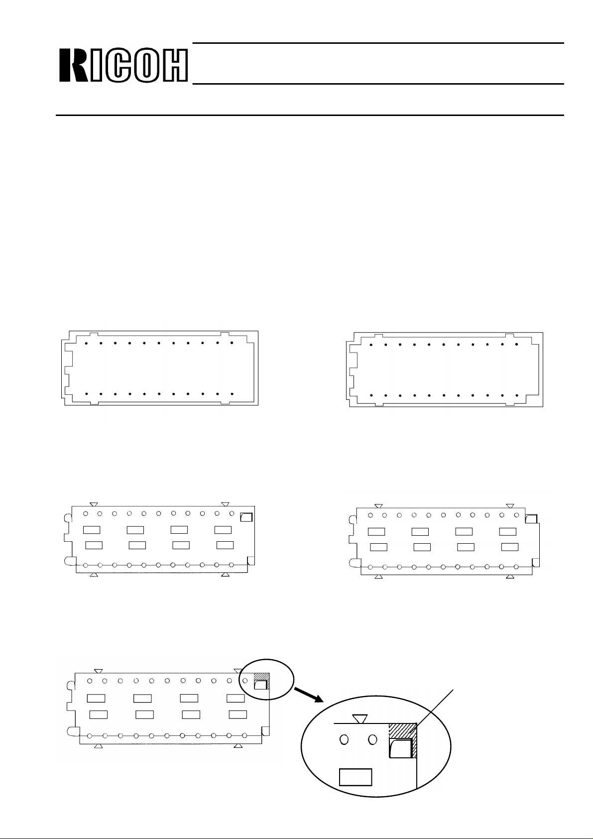
The following problem will occur with the 22 pin-connector which has been used between the
FCU and NCU in some models.
FAX T.S. Section, T.S. Department
Assistant General Manager
H. Motojima
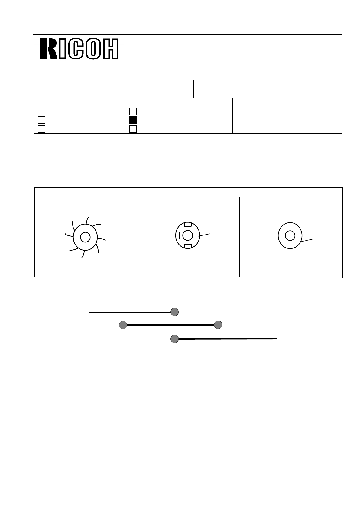
[Cause]
To pr e ve nt the pin fr om bend ing and to improve reliability, the vender has mod ifie d the style of
the connector (both holder and header) without a part number change.
Ho wever, th ere is no interchangeabilit y between the n ew one and the old one.
[Symptom]
If the old holder is connected with the new header on the FCU and NCU, the contact between
them will be incomplete.
Interchangeability of each type is shown below. (See figure A)
Old Holder New Holder
Old
Header
New
Header
OO
XO
After the January.
1991 pr oduction
After the April.
1991 pr oduction
[ Solution]
If the holder is an old one and the header is a new one, the edge of the holder must be cut off
when the NCU and/or FCU are replaced in the field. (See figure B)
Page 3
New Holder
←
Page 2
Technical Bulletin
No.GENERAL-002
Issued on
June 12, 1992
Subject:
22 pin - Connector interchangeability
[Applicable Models]
Model L Series
Model C Series
FAX 8 2
When you replace the FCU and/or the NCU in the above models, check the style of the follow-
ing points in advan ce.
a) Edge of the header on the FCU/NCU.
b) Edge of the holder at both sides of FCU-NCU harness.
Old Header
Old Holder
←
←
[Figure A]
←
New Header
Cut off
$
$
Old Holder
[Figure B]
Page 4
2
Page 1/1
Technical Bulletin No. GENERAL-003
SUBJECT: Notice for FCE ROM reinstallation.
PREPARED BY: H.Someya
CHECKED BY:
CLASSIFICATION:
Action Required Revision of service manual
Troubleshooting Information only
FROM: 2nd T.S. Section
MODEL: IXO
ZB
PF-2
Retrofit Information Other
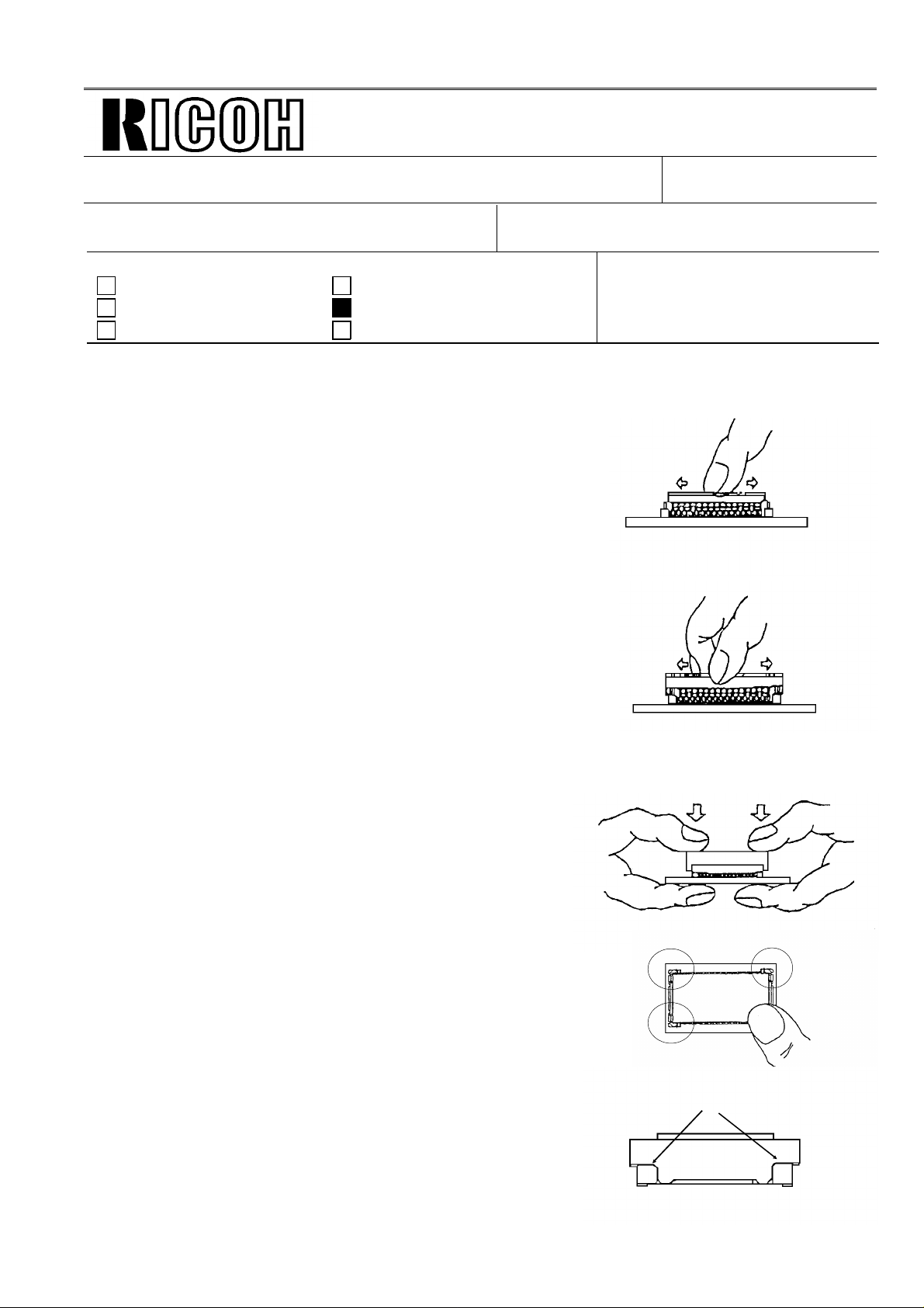
Reinstall the ROM on the FCE according to th e followin g pro ceduce.
1. Put the ROM in the FCE mount.
Note: The ROM must be slightly loose in the mount.
2. Put the frame on the mount.
DATE:Oct. 25th 1993
Note: The frame must be slightly loo se on the moun t.
3. There are two ways to set the frame.
1) Hold down both sides of the frame with bo th thu mbs.
Note: Do not push down on the ROM.
2) Put the tool (P/N: N/A) on the frame.
Hold down both sides of the too l wit h bo th thu mbs.
4. Push down each corner to ensure secure setting
of the frame.
5. Check that each hook is locked comp let ely.
1
3
4
same spaces
Page 5

Page 1/2
Technical Bulletin No. GENERAL-004
SUBJECT: Black bands/lines on the received cop y
PREPARED BY: H.Yokoyama
CHECKED BY:
CLASSIFICATION:
Action Required Revision of service manual
Troubleshooting Information only
Retrofit Information Other
FROM: 2nd T.S. Section
MODEL: USA only
CSO, CFO, CS1/CRO
DATE:
November 11th, 1993
[Problem]
On the received copies, bla ck ban ds or line s may
be printed, especially on the right hand side.
[Cause]
Toner or dust is attached to the charge corona wire.
[Modification]
The electric current of the charge coron a will be
increased to avoid applying uneren charg to the
master which is caused by a dirty corona wire.
Because of the increase of the ele ctric curre nt , th e
distance betwee n th e grid plate and the coro na
wire will be changed to keep the charge on the
master belt the same as before modification.
• H081 2870 → H081 2854 Eraser Ass’y
• H081 5030 → H081 5020 Power pack (CSO/CFO)
H510 5030 → H510 5020 Power pack (CRO/CS 1)
<Eraser Ass’y>
• The thickness of the cleaning blad e of the cleaner will be changed to incre ase the
cleaning ability (4mm → 5mm)
• The distance between the gride plate and charg e wire will be cha nged (6mm → 8mm)
<Power pack>
• The range and initial value of the VRC (VR for the charg e coro na ) will be change d.
The above modification will ta ke pla ce fro m t he De cemb er 1st prod uction.
Page 6

Page 2/2
Technical Bulletin No. GENERAL-004
SUBJECT: Black bands/lines on the received cop y
DATE:
November 11th, 1993
[Countermeasure in the field]
The countermeasu re method depends on the CV (Cop y Volu me) of the machine.
• If the CV is less than 400 sheets/month
Turn VRC on the power pack to the maximum (Turn the VR clockwise until it stops)
• If the CV is more than 400 sheet s/mo nth
Change the Eraser to the modified one and turn VRC on the power pack to the maximum.
Note:The increase in the powe r of VRC may de crease the life time of the master unit, so for
customers whose ACV/month is more than 400 sheets, the Erase r shou ld be chan ge d.
[Request]
The essence of this problem is a dirty cha rge corona wire, so please do the follo wing
• When a sales or service person visits a customer (at PM or EM), clea n the charge
corona wire with the built-in cleaner
• Advise the customer to clean th e charge corona wire at a certain interval or if the
customer sees black bands/lines on the receive d copy.
Page 7
Page 1/2
Technical Bulletin No. GENERAL-005
SUBJECT: Black bands/lines on the received cop y
PREPARED BY: H.Yokoyama
CHECKED BY:
CLASSIFICATION:
Action Required Revision of service manual
Troubleshooting Information only
Retrofit Information Other
FROM: 2nd T.S. Section
MODEL: Europe, Asia
CSO, CFO, CRO
DATE:
Feb. 3rd, 1994
[Problem]
On the received copies, bla ck ban ds or line s may
be printed, especially on the right hand side.
[Cause]
Toner or dust is attached to the charge corona wire.
[Modification]
The electric current of the charge coron a will be
increased to avoid applying uneren charg to the
master which is caused by a dirty corona wire.
Because of the increase of the ele ctric curre nt , th e
distance betwee n th e grid plate and the coro na
wire will be changed to keep the charge on the
master belt the same as before modification.
• H081 2870 → H081 2854 Eraser Ass’y
• H081 5030 → H081 5020 Power pack (CSO/CFO)
H510 5050 → H510 5051 Power pack (CRO)
<Eraser Ass’y>
• The thickness of the cleaning blad e of the cleaner will be changed to incre ase the
cleaning ability (4mm → 5mm)
• The distance between the gride plate and charg e wire will be cha nged (6mm → 8mm)
<Power pack>
• The range and initial value of the VRC (VR for the charg e coro na ) will be change d.
The above modification will take pla ce fro m t he Feb. 1st pro du ctio n.
Page 8

Page 2/2
Technical Bulletin No. GENERAL-005
SUBJECT: Black bands/lines on the received cop y
DATE:
Feb. 3rd, 1994
[Countermeasure in the field]
The countermeasu re method depends on the CV (Cop y Volu me) of the machine.
• If the CV is less than 400 sheets/month
Turn VRC on the power pack to the maximum (Turn the VR clockwise until it stops)
• If the CV is more than 400 sheet s/mo nth
Change the Eraser to the modified one and turn VRC on the power pack to the maximum.
Note:The increase in the powe r of VRC may de crease the life time of the master unit, so for
customers whose ACV/month is more than 400 sheets, the Erase r shou ld be chan ge d.
[Request]
The essence of this problem is a dirty cha rge corona wire, so please do the follo wing
• When a sales or service person visits a customer (at PM or EM), clea n the charge
corona wire with the built-in cleaner
• Advise the customer to clean th e charge corona wire at a certain interval or if the
customer sees black bands/lines on the receive d copy.
Page 9
Magnet
Page 1/1
Technical Bulletin No. GENERAL-006
SUBJECT: CTM modification
DATE:
April, 11th, 1994
PREPARED BY: H.Yokoyama
CHECKED BY:
CLASSIFICATION:
Action Required Revision of service manual
FROM: 2nd T.S. Section
MODEL:
CSO, CFO, CS1
Troubleshooting Information only
Retrofit Information Other
To avoid toner from being spilt inside the machin e, the toner collection roller of th e CTM will be
modified.
<Figure>
Previous
Type A Type B
Brush 4 Magnets Magnet surface
After modification
Magnet
Black lot no. is printed on the
carton box.
<Expected arrival period>
Previous Type
Type A
Type B
’94.1
Red lot no. will be printed on
the carton box.
’94.6
’94.8
’94.6
Blank lot no. will be printed
on the carton box.
Page 10

Page 1/1
Technical Bulletin No. GENERAL-007
SUBJECT: Super Fine (16 x 15.4/mm) bit in NSF Frame
PREPARED BY: H.Yokoyama
CHECKED BY:
CLASSIFICATION:
Action Required Revision of service manual
Troubleshooting Information only
Retrofit Information Other
FROM: 2nd T.S. Section
MODEL:
K200, K83
DATE: Apr, 11th, 1994
<Problem>
LHO may not transmit to K200 or K83 in super fine mode (16 x 15.4 l/mm, or 400 dpi x 400dpi)
<Cause>
The bit assignment fo r the NSF f rame has be en chan ge d.
<Action>
If you face this problem, cha ng e the following bit switche settings.
K200: G3 CCU SW10 Bit 0 to "1"
K83: SW20 Bit 0 to "1"
Page 11

Page 1/1
Technical Bulletin No. GENERAL-008
SUBJECT: Replacing the toner cassette
PREPARED BY:H. Yokoyama
CHECKED BY:
CLASSIFICATION:
Action Required Revision of service manual
Troubleshooting Information only
Retrofit Information Other
The instruction of the operator’s manual for replacing the toner cassette (CTM) is wrong.
We will insert the errata sheet to the operator’s manual.
Wrong: 1. Switch off the machine.
Correct: Keep the power switch on when replacing the toner cassette.
FROM: 2nd T.S. Section
MODEL:
CSO, CFO, CRO, CS1
DATE:
April, 11th, 1994
Page 12

Page 1/1
Technical Bulletin No. GENERAL-009
SUBJECT: Vertical Black Lines
PREPARED BY: H.Yokoyama
CHECKED BY: S.Hamano
CLASSIFICATION:
Action Required Revision of service manual
Troubleshooting Information only
Retrofit Information Other
[Problem]
Vertical black lines appear on the printed image.
[Cause]
The toner may stick on the Hot Roller, Fusing Stripper, Thermistor, an d The rmostat and this
toner may damage the surf ace of th e Hot Roller. Then, during copyin g toner is transferred by
the scratched part of the roller to cause vertical bla ck lines on the print ed image .
FROM: 2nd T.S. Section
MODEL:
CSO, CFO, CRO, CS1
DATE:
Jury. 30, 1994
[Countermeasu re]
The material of the surface of the Hot Roller ha s bee n cha nged to pre ven t th e tone r from
sticking on the Roller by the following modification
H0812100D → E
Because of the ab ove mo dif ication, the vende r has be en ch an ge d.
[Effective S/N]
H081-24, 40, 46, 51, 54 , 59, 60: Oct., 1993 ~
H510-20: R88310006 09 ~
21, 22, 27, 30, 40, 51, 59, 60: Nov., 1993 ~
H082-20, 23, 30, 40, 51 , 59 , 60 : Nov. , 19 93 ~
H511-20, 21, 22, 27: Nov. , 19 93 ~
[Action]
Clean the Fusing Stripper, The rmisto r and Thermo stat and take out the tone r from th em when
visit the customer.
Page 13

Page 1/1
Technical Bulletin No. General-010
SUBJECT: Digital Audio Tape (DAT)
PREPARED BY: Y.Okunishi
CHECKED BY: S.Hamano
CLASSIFICATION:
Action Required Revision of service manual
Troubleshooting Information only
Retrofit Information Other
Ricoh will analyze communication pro blems, which can not be solved locally, using DAT.
Please follow the fo llowin g recording procedure for DAT to be sen t to Ricoh for the analysis of
communication problems.
1) Set the modem test mo de at th e loca l f ax mach ine and send a 2100Hz signal out.
Record it for 3 minutes.
2) Have the machine at th e other side send a 2100Hz signal o ut and re cord it for 3 minu tes.
Note: [1] Make a 5 second or lon ge r pau se be twe en 1) and 2) t o sep ara te the m .
[2] Do not record un-necessary noise.
FROM: 2nd T.S. Section
MODEL:
DATE:
Dec. 15, 1994
General
3) Record five fax communications.
Page 14

T
echnical
B
ulletin
RTB Correction
Reissue date: 30-Jun-98
The items in bold italic have been corrected or added.
Model:
General
Date:
15-Jan-98
No:
PAGE: 1/3
C
011
Subject:
From:
Classification:
Check Items
The following functions for which the clock timer is used were checked to see whether or
not they will function correctly at 0:00 on Jan. 1, 2000.
1) Display and print of the date and time
2) Clock adjustment
3) Send later mode with memory and without memory
Year 2000 Problem
QAC 2nd Field Information Dept.
Troubleshooting
Mechanical
Paper path
Other (Info only)
The year must be changed to 2000 or 00 from 1999 or 99 and the date must be kept
correctly after the year 2000.
The date and time can be adjusted after the start of the year 2000.
The calling time must be the set time after the start of the year 2000.
Part information
Electrical
Transmit/receive
Prepared by:
Action required
Service manual revision
Retrofit information
Y.Okunishi
4) Automatic re-transmission.
When a communication error occurs, the machine calls the same dest ination again
automatically after an interval. This must function correctly after the start of the year
2000.
5) Weekly timer and night timer
The energy saver mode (heater) control must work correctly.
6) Displayed date after a power failure
The correct date must be kept by the battery.
Models Checked
1) K50 series (FAX10, 20, 60, etc.)
2) K70 series (FAX90, 95, 105, etc.)
3) K90 series (FAX80, 85, 75, 86, etc.)
4) LE series (FAX08, 09, Phone fax for ATT, etc.)
5) B series (B1, RF810, FAX12, FAX300, etc.)
6) ZB series (FAX220, FAX240, Innfax, etc.)
7) BARBARA series (RF01, 02, 03, 05, 06, etc.)
Page 15

T
echnical
B
ulletin
PAGE: 2/3
Model:
8) OX series (FAX21, 22)
9) PF series (PF-1, PF-2)
10) A series (FAX500, 550, etc.)
11) B60 series (FAX170, 180, etc.)
12) K100 series (FAX1000L, 1010L, etc.)
13) K105 series (FAX4000L, etc.)
14) K200 series (FAX7000L, etc.)
15) KV series (FAX2800L, 1200L, etc.)
16) C series (FAX2500L,3000L, 3500L, 4500L, 5600L, etc.)
17) L80 (MV715)
18) I series (FAX800, 880, 680, MV74, etc.)
19) F\L series (FAX2700L, 3700L, 4700L, MV310, etc.)
20) FX7, LX7 (FAX1700L, MV106, FAX1750MP, etc.)
21) L20 series (Aficio FX10)
General
Date:
15-Jan-98
No:
011
C
22) K10 series (FX120, Rapicom120, FX210/230, Rapicom210/230, etc.)
23) K20 series (FX5000, Rapicom5000, etc.)
24) K60 series (FAX610, Rapicom610, etc.)
25) K83 series (FAX830, Rapicom830, etc.)
26) FR4, FR6 (FAX4800L, FAX3800L, etc.)
Problem found
Most models, except the following models, will not experience any problems.
1) AFO (FAX 500/550/580, NRG 9620, Infotec 3301/3305, Nashua F492)
CSO (FAX 3000/3100/3200, NRG 9660/9661/9662, Omnifax L40/41,
Savin FAX 3660/3620, Infotec 3660)
CS1 (FAX 3500L,NRG 9665, Omnifax L46, Savin FAX 3670)
CRO (FAX 2500L/2600L, NRG 9650, Omnifax L42, Savin FAX 3630, Infotec 3661)
a) The day of week, that appears on the display only in the clock adjustment
mode, is returned back to SUNDAY whenever the clock adjustment is done
after the start of the year 2000.
So, the programmed weekly timer does not work correctly. (AFO’ s do not
have the weekly timer.)
If the clock adjustment is not done after the start of the year 2000, the date and
the day of week is kept correctly.
b) Clock adjustment is available only for the year 91 through 99. The other years
cannot be set. (Month, day and time can be adjusted.)
Page 16

T
echnical
B
ulletin
PAGE: 3/3
Model:
2) K200 (FAX7000L)
3) K60 series (FAX610, Rapicom610, Infotec6550)
General
a) Clock adjustment is available only for the years 88 through 99. The other years
cannot be set. (Month, day, and time can be adjusted.)
b) The send later mode does not function (no calling happens) if it pa sses the time
into the year 2000.
No report is printed. The message in the memory is not cleared automatically
but must be cleared by user operation.
c) Automatic re-transmission is not done if the year 2000 starts in the interval after
the transmission failure.
The message in the memory is not cleared automatically but must be cleared
by user operation.
d) The display year is returned back to 88 after a power failure after the start of
the year 2000.
K83 series (FAX830, Rapicom830, Infotec6750)
Date:
15-Jan-98
No:
011
C
a) The day of week is not displayed correctly after the start of the year 2000.
b) The send later mode does not function (calling at 0:00AM January 1st
2000).
c) The display year is returned back to 85 when the power fails after the
start of the year 2000.
The other functions in these models work correctly.
Schedule for the countermeasure ROMs
1) AFO, CSO, CS1, CRO:
In
K200 (FAX7000L):
2)
In May 1998
3) K60, K83: A ROM will not be available.
April
1998.
(The corrected version will be in July 1998.)
RC RE ASIA
∗ ∗ ∗
Page 17

T
Model:
General
echnical
B
ulletin
Date:
15-Dec-97
No:
PAGE: 1/1
012
Subject:
From:
Classification:
Master ROM Access Time
QAC Field Information Dept.
Troubleshooting
Mechanical
Paper path
Other ( )
Part information
Electrical
Transmit/receive
Prepared by:
Action required
Service manual revision
Retrofit information
K.Moriizumi
SYMPTOM
When updating the ROM in the machine using EPROMs, NG is displayed on the LCD. The
updating is unsuccessful.
CAUSE
When options (PCFE, HD, ISDN etc.) are installed in the ma chine, the system data bus is
crowded. If EPROMs with an access time of 120ns are used for updating the ROM inside
the machine, the CPU read setup time is too short, so the program updating is
unsuccessful.
SOLUTION
Use EPROMs with an access time of 100ns or less for all fax machines.
For example:
M27C4001-10F1: OK
27C040-10: OK
M27C4001-12F1: NG
D27C4001D-12: NG
We recommend using P/N 1905-0020 (M27C4001-10F1) for the blank EPROM.
RC RE ASIA
∗∗ ∗
Page 18

T
MB Correction
Reissue date : 15-Jun-98
The items in bold italic have been corrected or added.
Model:
General
echnical
B
ulletin
Date:
15-Mar-98
No:
PAGE: 1/1
A
013
Subject:
From:
Classification:
We would like to inform you of the investigation results regarding year 2000 compliance in
scanners and printers delivered to your market.
Scanners: No problems
◊
Printers: No problems
◊
As you know, both products have timers in the circuits on the controller boards and other
PCBs. However, the timers are used only for controlling th e circuits, not as timer functions
such as Send later mode, Automatic re-transmission, used in fax products. Thus, there are
no year 2000 problems with these products.
Year 2000 compliance, Scanners and Printers
QAC Field Information Dept.
Troubleshooting
Mechanical
Paper path
Other ( )
Part information
Electrical
Transmit/receive
Prepared by:
Action required
Service manual revision
Retrofit information
A.Kato
Scanner models: RS300, RS311, RS322, RS632
IS400, IS410, IS420, IS430
FS1-S, FS-2
Printer models: LP1060, LP1200, LP4080/81, LP4150
LPM20, LPM32, LPM38
RC RE ASIA
∗ ∗
Page 19

T
Model:
General
echnical
B
ulletin
Date:
15-Apr-98
No:
PAGE: 1/3
014
Subject:
From:
Classification:
The year 2000 issue was explained in RTB No. General-011B.
That RTB explains only the technical matters of what will happen after the year 2000 in
some models, and the countermeasures.
At this time, we would explain how to talk with customers about the year 2000 issues
related to fax machines.
Basically, we can say to the customers that there is no major issue reated to basic
operation after the year 2000, and they don't need to take any preventative action before
the year 2000.
The only thing that the customers need to know is that the following operations will be
changed after the year 2000.
Action Plan for the Year 2000 Issues
QAC Field Information Dept.
Troubleshooti ng
Mechanical
Paper path
Other (Info only)
Part information
Electrical
Transmit/receive
Prepared by:
Action required
Service manual revision
Retrofit information
Y.Okunishi
1. AF0 (FAX 500/550/580, NRG 9620, Infotec 3301/3305, Nashua F492)
CS0 (FAX 3000/3100/3200, NRG 9660/9661/9662, Omnifax L40/41,
Savin FAX 3660/3620, Infotec 3660)
CS1 (FAX 3500L,NRG 9665, Omnifax L46, Savin FAX 3670)
CR0 (FAX 2500L/2600L, NRG 9650, Omnifax L42, Savin FAX 3630, Infotec 3661)
First, please do not forget to inform the customers that they don't need to do anything if
they do not go into the clock adjustment mode.
A) Adjustment of the year
A-1) For the year 2000
①Set the clock to 11:59 PM (or 23:59) on December 31 1999, and wait for one minute.
②The year changes to 2000 automatically, then set the current time.
(Do not change the year.)
A-2) For the year 2001
③After the above step ①, set the clock to 11:59 PM (or 23:59) on December 31 2000, and
wait for one minute.
④The year changes to 2001 automatically, then set the current time.
(Do not change the year.)
A-3) For years 2002 and later, repeat the same procedure as above.
Page 20

T
Model:
General
echnical
B
ulletin
Date:
15-Apr-98
No:
PAGE: 2/3
014
B) Adjustment of the weekly timer (Heater timer)
This is only for customers who use the weekly timer. (We do not think that many
customers are using this function.)
Please recommend adjusting the timer on Sunday if the customer can do it.
If they cannot do it on Sunday, the ROM should be changed to the new one.
The new ROM includes the countermeasure for the above A) also.
2. K200 (FAX7000L)
A) Adjustment of the year
First, please do not forget to inform the customers that they don't need to do anything if
they do not go into the clock adjustment mode.
A-1) For the year 2000
Set the clock to 11:59 PM (or 23:59) on December 31 1999, and wait for one minute.
①
The year changes to 2000 automatically, then set the current time.
②
(Do not change the year.)
A-2) For the year 2001
Except AF0
••••
After the above step ①, set the clock to 11:59 PM (or 23:59) on December 31 2000,
③
and wait for one minute.
The year changes to 2001 automatically, then set the current time.
④
(Do not change the year.)
A-3) For years 2002 and later
Repeat the same procedure as above.
If the customer switches off the machine after the year 2000, the year displayed returns to
1988. In this case, follow the above procedure to adjust the clock.
B) Send later mode
Please notify the customer that they should not use send later mode on December 31st
1999, if the transmission will be done on the next day.
If the customer cannot guarantee that they will follow this advice, the ROM should be
changed.
Page 21

T
Model:
Schedule of the countermeasure ROMs
1) AFO, CSO, CS1, CRO:
2) K200 (FAX7000L):
Both are delayed.
∗
General
In May 1998.
In May 1998.
echnical
B
ulletin
Date:
15-Apr-98
No:
PAGE: 3/3
014
RC RE ASIA
∗ ∗ ∗
Page 22

RICOH Technical
Model:
General
Bulletin
Date:
29-May-98
No:
PAGE: 1/1
015
Subject:
From:
Classification:
Polarity Detection (Additional Bit Switch)
Technical Service Department.
Troubleshooting
Mechanical
Paper path
Other ( )
Part information
Electrical
Transmit/receive
Prepared by:
Action required
Service manual revision
Retrofit information
K. Misugi
SYMPTOM
This RTB is to clarify the symptom for the following error code.
Error code 0-52: Polarity change detected during communication.
CAUSE
Polarity change is detected during communication and the machine disconnects the line in
the following conditions (error code 0-52).
1. When the machine is at the Rx side (receiving a message) and when G3 bit switch 0B
bit 1 (Protocol requirements: Spain) is set to 1 (Enabled).
The machine immediately disconnects the line when it detects polarity change after
receiving DIS/NSF.
2. When the machine is at the Tx side (transmitting a message) and when G3 bit switch
03 bit 7 is set to 1.
The machine immediately disconnects the line if it detects polarity change twice after
receiving DIS/NSF.
NOTE:
G3 Switch 03
No FUNCTION COMMENTS
RC RE ASIA
The following explanation must be added to the service manual.
(All F/L series: FX6, FX6Mk2, FX4, FX7, LX7, LSO, LSOMk2, LFO, FR6, FR4)
1:
7 Polarity detection during
communication
0: Disabled 1: Enabled
The machine disconnects the line when it
detects polarity change twice after
receiving DIS/NSF.
This detection is enabled only when the
machine is in Tx mode.
üüü
Page 23

T
Reissued: 30-Apr- 99
echnical
B
ulletin
PAGE: 1/4
Model:
General
Date:
15-Jan-99
No.:
RGene011d
RTB Correction
The items in bold italics have been corrected or added.
Subject:
From:
Classification:
Check Items
The following functions for which the clock timer is used were checked to see whether or
not they will function correctly at 0:00 on Jan. 1, 2000.
1) Display and printing of the date and time
2) Clock adjustment
Year 2000 Problem
Technical Service Dept., GTS Division
Troubleshooting
Mechanical
Paper path
Other ( )
The year must be changed to 2000 or 00 from 1999 or 99 and the date must be kept
correctly after the year 2000.
The date and time can be adjusted after the year 2000.
Part information
Electrical
Transmit/receive
Prepared by:
Action required
Service manual revision
Retrofit information
Y. Okunishi
3) Send later mode with memory and without memory
The calling must be made at the set time after the year 2000.
4) Automatic re-transmission.
When a communication error occurs, the machine calls the same dest ination again
automatically after an interval. This will function correctly afte r the yea r 2 000.
5) Weekly timer and night timer
The energy saver mode (fusing unit) control will work correctly.
6) Displayed date after a power failure
The correct date will be kept by the battery.
7) Leap year
Machines must recognize the year 2000 as a leap year and the above 1) – 6) will
function.
8) The year 2001
The above 1) – 6) will function in the year 2001.
Page 24

T
Reissued: 30-Apr- 99
echnical
B
ulletin
PAGE: 2/4
Model:
Models Checked
1) K50 series (FAX10, 20, 60, etc.)
2) K70 series (FAX90, 95, 105, etc.)
3) K90 series (FAX80, 85, 75, 86, etc.)
4) LE series (FAX08, 09, Phone fax for ATT, etc.)
5) B series (B1, RF810, FAX12, FAX300, etc.)
6) ZB series (FAX220, FAX240, Innfax, etc.)
7) BARBARA series (RF01, 02, 03, 05, 06, etc.)
8) OX series (FAX21, 22)
9) PF series (PF-1, PF-2)
10) A series (FAX500, 550, etc.)
11) B60 series (FAX170, 180, etc.)
12) K100 series (FAX1000L, 1010L, etc.)
General
Date:
15-Jan-99
No.:
RGene011d
13) K105 series (FAX4000L, etc.)
14) K200 series (FAX7000L, etc.)
15) KV series (FAX2800L, 1200L, etc.)
16) C series (FAX2500L,3000L, 3500L, 4500L, 5600L, etc.)
17) L80 (MV715)
18) I series (FAX800, 880, 680, MV74, etc.)
19) F\L series (FAX2700L, 3700L, 4700L, MV310, etc.)
20) FX7, LX7 (FAX1700L, MV106, FAX1750MP, etc.)
21) L20 series (Aficio FX10)
22) K10 series (FX120, Rapicom120, FX210/230, Rapicom210/230, etc.)
23) K20 series (FX5000, Rapicom5000, etc.)
24) K60 series (FAX610, Rapicom610, etc.)
25) K83 series (FAX830, Rapicom830, etc.)
26) FR4, FR6 (FAX4800L, FAX3800L, etc.)
27) Schmidt 1(FAX2000L)
28) Schmidt 3
Page 25

T
Reissued: 30-Apr- 99
echnical
B
ulletin
PAGE: 3/4
Model:
Problems found
Most models, except the following, will not experience any problems.
1) AFO (FAX 500/550/580, NRG 9620, Infotec 3301/3305, Nashua F492)
General
CSO (FAX 3000/3100/3200, NRG 9660/9661/9662, Omnifax L40/41,
Savin FAX 3660/3620, Infotec 3660)
CS1 (FAX 3500L,NRG 9665, Omnifax L46, Savin FAX 3670)
CRO (FAX 2500L/2600L, NRG 9650, Omnifax L42, Savin FAX 3630, Infotec 3661)
a) The day of the week that appears on the display only in the clock adjustment
mode is returned back to SUNDAY every time the clock adjustment is done
after the year 2000.
So, the programmed weekly timer does not work correctly. (AFO does not
have the weekly timer.)
If the clock adjustment is not done after the year 2000, the date and the day of
week is kept correctly.
b) Clock adjustment is available only for the year 91 through 99. The other years
cannot be set. (Month, day and time can be adjusted.)
Date:
15-Jan-99
No.:
RGene011d
2) K200 (FAX7000L)
a) Clock adjustment is available only for the years 88 through 99. The other years
cannot be set. (Month, day and time can be adjusted.)
b) The send later mode does not function (no calling happens) if time passes into
the year 2000.
No report is printed and the rest of the message in the memory is not cleared
automatically, but it is cleared by user operation.
c) Automatic re-transmission is not done if the year 2000 starts in the interval after
the transmission failure.
The rest of the message in the memory is not cleared automatically but it is
cleared by user operation.
d) The displayed date is reset and turned back to ‘88 in the event of a power
failure after the year 2000.
e) The day of the week will be wrong if the clock or date information is
adjusted after the year 2000.
Page 26

T
Reissued: 30-Apr- 99
echnical
B
ulletin
PAGE: 4/4
Model:
3) K60 series (FAX610, Repicom610, Infortec6550)
The other functions in these models work correctly.
Schedule of the countermeasure ROMs
1) AFO, CSO, CS1, CRO:
2) K200(FAX7000L):
General
K83 series (FAX830, Repicom830, Infortec6750)
a) The day of the week is not displayed correctly after the year 2000.
b) The send later mode does not function (calling at 0:00AM January 1st 2000)
c) The display year is returned back to 85 when the power fails after the year
2000.
In April 1998.
In May 1998. (Corrected version will be in July 1998.)
Date:
15-Jan-99
No.:
RGene011d
3) K60, K83:
The ROM will not be available.
RC REBV ASIA
∗∗∗
Page 27

T
echnical
ulletin
B
PAGE: 1/1
Model:
Subject:
From:
Classification:
General
File Dividing Utility Program.
GTSS Field Information Dept.
Troubleshooting
Mechanical
Paper path
Other ( )
Part information
Electrical
Transmit/receive
Date:
15-Jul-99
Prepared by:
No.:
RGenF016
K. Moriizumi
Action required
Service manual revision
Retrofit information
SYMPTOM
It is impossible to use the utility program HEXDIV.EXE for the Schmidt1 and F66 in the
normal way. However, using this program, the firmware file can be divided into 2 or 4 files
so that it can be written to the EPROM.
SOLUTION
If some options are added to the command line, the firmware files for the Schmidt1 and
F66 can be divided.
Options
– b start address
– e end address
– M offset
– s : The source file is in the Motorola S format
– S: The output file is in the Motorola S format
– O file name: The output file name
Foe example, the file for the Schmidt1 can be divided into 2 files as follows.
C:\> hexdiv-bf00000 -ef7ffff -Mf00000 -s -S -O H5457200.LOW H5457200.MS
C:\> hexdiv-bf80000 -effffff -Mf80000 -s -S -O H5457200.HIG H5457200.MS
H5457200.LOW (or HIG) is the output file name, H5457200.MS is the source file name.
RC REBV ASIA
∗∗∗
Page 28

RICOH Technical
Bulletin
PAGE: 1/1
Model:
Subject:
From:
Classification:
The new FCC regulations will be applied to products produced after December 19, 1999.
The following features will be affected by these changes and the firmware changed accordingly.
- Redialing Limited to only one time if the machine cannot detect the busy and re-order tones.
- Transmission Deadline function (TRD) The maximum number of times for redialing is limited to 14. Therefore, this function will not be
available.
- Affected machines Product
Fax
LFO NO 4 NO NO 1 NO
FR6, FR4 NO 4 YES NO 1 NO
Schmidt3 YES 4 YES YES 4 NO
Schmidt1 NO 1 NO NO 1 NO
Kaiser1 No production YES 4 NO *1, *3
Digital PPC
NAD NO 4 YES NO 1 NO
Stinger-C1 NO 1 YES YE 4 NO
Russian-C1 NO 1 NO YES 4 NO *3
GF10B NO 2 NO NO 1 NO *2
Digital Color
Lilac2 No production NO 1 NO *1
Option
S G3 Option NO 4 - NO 1 NO *3, *4
Note:
*1: The change will be applied from the first lot of mass-production.
*2: No memory transmission is available.
*3: When this option is installed, redialing from the main frame is also limited to one time.
*4: TRD is controlled by the main frame.
For details of these changes, please refer to the MB or RTB that will be issued for each model.
Products with FAX function (US version)
For New FCC Regulations
Technical Servers Dept., GTS Division
Troubleshooting
Mechanical
Paper path
Other ( )
Before change After change
Tone
detection
Redialing TRD T one
Part information
Electrical
Transmit/receive
detection
Date:
30-Nov-99
Prepared by:
Redialing TRD
Action required
Service manual revision
Retrofit information
No.:
Y. Okunishi
Note
RGenF017
RC REBV ASIA
*
 Loading...